UFo liGhTinG - ufo-licht.de · UFo liGhTinG 7 insTallaTion CONNECTION There are 2 main connections...
24
UFo lIGHTING FIbre oPTIc & led lIGHTING sysTeMs revIsIoN: b1 UFo coMPacT 150w dMX+ UNIversal lIGHT soUrce Please read THIs User GUIde beFore INsTallING, coNNecTING or oPeraTING THIs lIGHT soUrce. User GUIde Models covered: UFo 150 cdMX+G-dcT / UFo 150 cdMX+G-dcT UFo 150 cdMX+G-dc / UFo 150 cdMX+G-cT UFo 150 cdMX+G-c / UFo 150 cdMX+G-d UFo 150 cdMX+P-dcT / UFo 150 cdMX+P-dc UFo 150 cdMX+P-cT / UFo 150 cdMX+P-c UFo 150 cdMX+P-d / UFo 70 cdMX+G-dcT UFo 70 cdMX+G-dc / UFo 70 cdMX+G-cT UFo 70 cdMX+G-c / UFo 70 cdMX+G-d UFo 70 cdMX+P-dcT / UFo 70 cdMX+P-dc UFo 70 cdMX+P-cT / UFo 70 cdMX+P-c UFo 70 cdMX+P-d
Transcript of UFo liGhTinG - ufo-licht.de · UFo liGhTinG 7 insTallaTion CONNECTION There are 2 main connections...
UFo liGhTinGFibre oPTic & led liGhTinG sysTems
revision: b1
UFo comPacT 150w dmX+ Universal liGhT soUrce
Please read This User GUide beFore insTallinG, connecTinGor oPeraTinG This liGhT soUrce.
User GUide
models covered:UFo 150 cdmX+G-dcT / UFo 150 cdmX+G-dcT
UFo 150 cdmX+G-dc / UFo 150 cdmX+G-cTUFo 150 cdmX+G-c / UFo 150 cdmX+G-d
UFo 150 cdmX+P-dcT / UFo 150 cdmX+P-dcUFo 150 cdmX+P-cT / UFo 150 cdmX+P-cUFo 150 cdmX+P-d / UFo 70 cdmX+G-dcTUFo 70 cdmX+G-dc / UFo 70 cdmX+G-cT
UFo 70 cdmX+G-c / UFo 70 cdmX+G-dUFo 70 cdmX+P-dcT / UFo 70 cdmX+P-dc
UFo 70 cdmX+P-cT / UFo 70 cdmX+P-cUFo 70 cdmX+P-d
inTrodUcTion
Thank you for purchasing this UFO light source.
Please read these instructions fully before connecting your unit to the electrical supply, andkeep them for future reference.
A high performance 70W or 150W metal halide light source for ultimate brightness which can befitted with up to three decorative wheels as follows:3DCT – Dimming, Colour and Twinkle2DC – Dimming and Colour2CT – Colour and Twinkle1C – Colour only1D – Dimming only
We do not recommend that the light source be left on for 24 hours a day, 7 days aweek as lamp life will be impaired. A switch off of 30mins per day is recommended.
2 150w Universal dmX+ User GUide
IMPORTANTWARNING – To reduce the risk of FIRE, ELECTRIC SHOCK OR INJURY TO PERSONS:
1. Unplug and allow to cool before replacing lamp.2. Always disconnect the unit from the power supply before opening or attempting
to perform any work on it.3. Do not touch hot lens, guard, or enclosure. 4. Do not look directly at lighted lamp. 5. Use only with the correct lamp wattage as detailed on the serial label.6. Do not touch the lamp at any time. Use a soft cloth. Oil from skin may damage lamp. 7. Do not operate product with missing or damaged guard, lamp containment barrier,lens or fibre optic harness. 8. Contact UFO for replacement lamp guard, lamp containment barrier, lens or fibre
optic harness9. Lamp types are matched to the ballast and different wattages/types cannot be
used.10. Ensure that the power supply is correct for the unit before powering it up.11. Always ensure that the unit is properly earthed.12. Do not expose the unit to rain or moisture.13. Never attempt to tamper with the wiring or other internal components.14. Keep the unit away from gas, oil and any other flammable or explosive materials.
3UFo liGhTinG
imPorTanT saFeTy inFormaTion
THIS PRODUCT MUST BE INSTALLED IN ACCORDANCE WITH THE APPLICABLEINSTALLATION CODE BY A PERSON FAMILIAR WITH THE CONSTRUCTION ANDOPERATION OF THE PRODUCT AND THE HAZARDS INVOLVED.
Do not operate without complete lamp enclosure in place or if lens is damaged.
KEEP HARNESS IN PLACE WHEN IN OPERATION.
CAUTION: Hot surface. Keep away from curtains and other combustible materials.
WARNING: RISK OF FIRE/INJURY TO PERSONS. Keep away from combustibles. Unplugto change lamp. Do not touch lamp.
WARNING: RISK OF FIRE. Do not place lamp where the overhead surface is closer than0.3m to the light source.
TYPE Y ATTACHMENT: If the external flexible cable or cord of this luminaire orassociated PSU/driver is damaged. It shall be exclusively replaced by the manufactureror his service agent or a similar qualified person to avoid a hazard.LOCATION: Do not locate this luminaire closer than 300mm from any flammablesurface.CLEARANCE/VENTILATION: It is imperative that a gap of 300mm is left around the unit.This is to allow air to circulate and prevent overheating. The location must have freeventilation and must not have a ambient temperature higher than that specified forthe luminaire.MOUNTING: This is a fixed luminaire. See separate mounting instructions for fixing tosurface.WARNING: Never look directly into the luminaire light source.
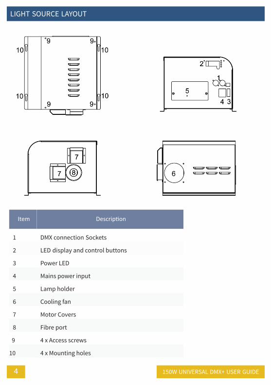
liGhT soUrce layoUT
4
Item Description
1 dmX connection sockets
2 led display and control buttons
3 Power led
4 mains power input
5 lamp holder
6 cooling fan
7 motor covers
8 Fibre port
9 4 x access screws
10 4 x mounting holes
150w Universal dmX+ User GUide
5UFo liGhTinG
insTallaTion
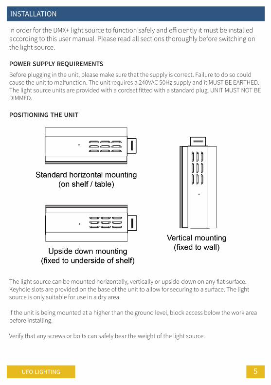
In order for the DMX+ light source to function safely and efficiently it must be installedaccording to this user manual. Please read all sections thoroughly before switching onthe light source.
POWER SUPPLY REQUIREMENTSBefore plugging in the unit, please make sure that the supply is correct. Failure to do so couldcause the unit to malfunction. The unit requires a 240VAC 50Hz supply and it MUST BE EARTHED.The light source units are provided with a cordset fitted with a standard plug. UNIT MUST NOT BEDIMMED.
POSITIONING THE UNIT
The light source can be mounted horizontally, vertically or upside-down on any flat surface.Keyhole slots are provided on the base of the unit to allow for securing to a surface. The lightsource is only suitable for use in a dry area.
If the unit is being mounted at a higher than the ground level, block access below the work areabefore installing.
Verify that any screws or bolts can safely bear the weight of the light source.

insTallaTion
6
Verify that the supporting structure can safely bear the weight of all installed units, cables and anyother equipment.
For horizontal mounting, it is recommended that the light source is secured to a solid surfaceusing 4 x M4 or M5 screws or bolts and the keyhole slots. This is particularly important if the lightsource location is not at ground floor level.
To mount the light source vertically, first securely install 4 x M4 or M5 screws or bolts at therequired distances so that they will line up with the keyhole slots. The light source can then bemounted onto them and slid into position. The bolts or screws MUST then be fully tightened.
To mount the light source under a surface, first securely install 4 x M4 or M5 screws or bolts at therequired distances so that they will line up with the keyhole slots. The light source can then bemounted onto them and slid into position. The bolts or screws MUST then be fully tightened.
CLEARANCE / VENTILATION
It is imperative that a gap of 300mm or more is left around the unit. This is to allow air to circulateand prevent overheating. The location must have free ventilation.
150w Universal dmX+ User GUide

7UFo liGhTinG
insTallaTion
CONNECTIONThere are 2 main connections required - the fibre port and the mains power supply. Connect andsecure the fibre optic connector to the fibre port before connecting the electrical supply. Never runthe light source with the fibre connector unplugged. For separate feed units, there will beadditional power connections required.
OPERATIONAfter installing and connecting the light source as described above, all you have to do is turn thepower on. The lamp will take 3-4 minutes to reach full brightness. This is normal for this type oflight source.
During the power up sequence the software version number and the model version is displayedmomentarily as detailed below:
If no light is produced, please consult the TROUBLESHOOTING section in this manual.
oPeraTion
8
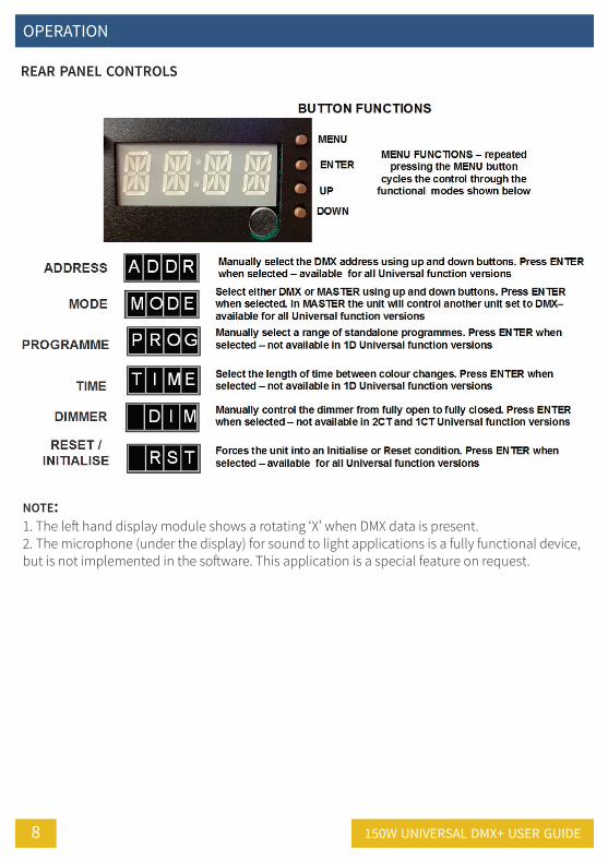
REAR PANEL CONTROLS
NOTE:1. The left hand display module shows a rotating ‘X’ when DMX data is present.2. The microphone (under the display) for sound to light applications is a fully functional device,but is not implemented in the software. This application is a special feature on request.
150w Universal dmX+ User GUide
9UFo liGhTinG
oPeraTion
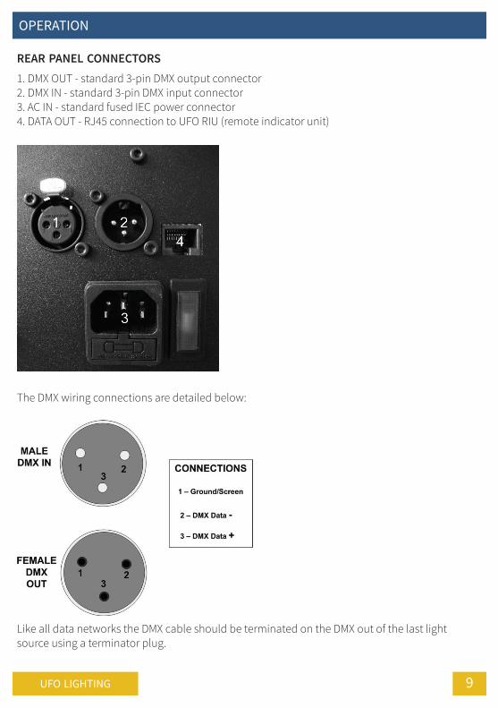
REAR PANEL CONNECTORS1. DMX OUT - standard 3-pin DMX output connector2. DMX IN - standard 3-pin DMX input connector3. AC IN - standard fused IEC power connector4. DATA OUT - RJ45 connection to UFO RIU (remote indicator unit)
The DMX wiring connections are detailed below:
Like all data networks the DMX cable should be terminated on the DMX out of the last lightsource using a terminator plug.

oPeraTion
10
The dmX+ light source has two modes of operation - standalone and dmX.
STANDALONE MODEIn standalone mode, the Compact DMX+ can be used in two ways - either as a single independentlight source or in master/slave configuration with several light sources connected together usingDMX cables.
In master/slave configuration all addresses are set the same and whatever program is selected onthe master unit will also be executed on the slave units.
DMX MODELight sources set in DMX mode can either be controlled by another Compact DMX+ in mastermode, or by a standalone DMX controller.
PROGRAMMING THE LIGHT SOURCEThe DMX+ can be programmed for various functions and modes from the rear panel controls asshown on the following pages.
RESET VIA DMXWhen resetting via DMX (Channel 1 - 128-191) care must be taken to ensure channels 2 to 5 are firstset to 0 value.
Failure to do this will result in the light source ‘freezing’. If a light source freezes in this way it can bereverted to normal by cycling the mains power off and then on again.
150w Universal dmX+ User GUide

11UFo liGhTinG
oPeraTion
������������
�����
� ���
��
� �����������������
��������
���
�� �������
���
�� ������
���
���
� ���������
����������������
�� �������
���
� ���
� � �� �������� �
�� � �� �������� �
���
� ���������
�����������������
��������
���
��
�� ������
���
� ����������������� ���������
�� �������
���
� ���
��� �� �������� �
��������
���
�� ������
���
� ����������������� ���������
���
� ���������
���� ��� ������������
�� �������
���
� � ��� �������� �
� ���
��������
���
��
�� ������
���
� ��������������������������������
� � ��������� �
���
� ���������
� �
� � ��������� �
� ��������� �
� � ���������� �
� � ��� �������� �
���
� ���������
�� � �� �������� �
���
� ���������
� �
��� �� �������� �
���
� ���������
� �
� � �� �������� �
���
� ���������
� �
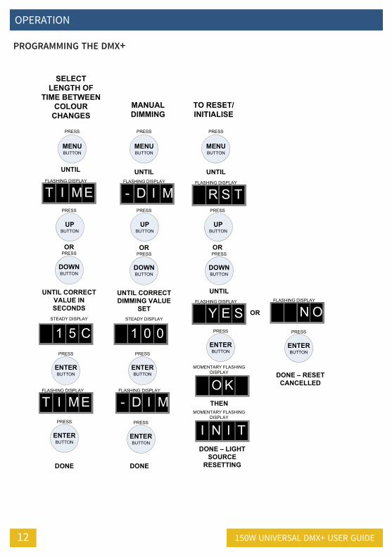
PROGRAMMING THE DMX+
oPeraTion
12
���������������
�� ���������������������
�����
�
����������������������������
��������
���
���������
���
���������
���
� ��� ������� �
���
�����������
�������� ���
���������
���
�����
� � ���� ��������� �
� � � ��� ��������� �
���
�����������
������������������
��������
���
�
���������
���
���������
���
�����
� ��� ��������� �
��������
���
���������
���
� � �� ��������� �
���
�����������
��������������������������
�
� � ���� ��������� �
���
���
�����������
��������������� ����������
���
� ��� ������� �
� � � ��� ��������� �
���
�����������
���
�����
�������� ����� �����
���� �
���
� � � ������� ����� �����
���� �
� � ��� ��������� �
���
�����������
���������������������
PROGRAMMING THE DMX+
150w Universal dmX+ User GUide
13UFo liGhTinG
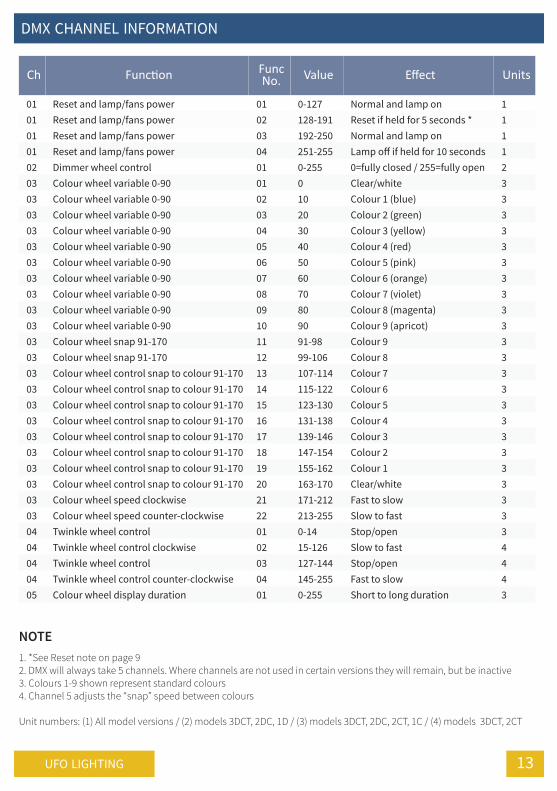
dmX channel inFormaTion
NOTE1. *See Reset note on page 92. DMX will always take 5 channels. Where channels are not used in certain versions they will remain, but be inactive3. Colours 1-9 shown represent standard colours4. Channel 5 adjusts the “snap” speed between colours
Unit numbers: (1) All model versions / (2) models 3DCT, 2DC, 1D / (3) models 3DCT, 2DC, 2CT, 1C / (4) models 3DCT, 2CT
Ch Function FuncNo. Value Effect Units
01 reset and lamp/fans power 01 0-127 normal and lamp on 101 reset and lamp/fans power 02 128-191 reset if held for 5 seconds * 101 reset and lamp/fans power 03 192-250 normal and lamp on 101 reset and lamp/fans power 04 251-255 lamp off if held for 10 seconds 102 dimmer wheel control 01 0-255 0=fully closed / 255=fully open 203 colour wheel variable 0-90 01 0 clear/white 303 colour wheel variable 0-90 02 10 colour 1 (blue) 303 colour wheel variable 0-90 03 20 colour 2 (green) 303 colour wheel variable 0-90 04 30 colour 3 (yellow) 303 colour wheel variable 0-90 05 40 colour 4 (red) 303 colour wheel variable 0-90 06 50 colour 5 (pink) 303 colour wheel variable 0-90 07 60 colour 6 (orange) 303 colour wheel variable 0-90 08 70 colour 7 (violet) 303 colour wheel variable 0-90 09 80 colour 8 (magenta) 303 colour wheel variable 0-90 10 90 colour 9 (apricot) 303 colour wheel snap 91-170 11 91-98 colour 9 303 colour wheel snap 91-170 12 99-106 colour 8 303 colour wheel control snap to colour 91-170 13 107-114 colour 7 303 colour wheel control snap to colour 91-170 14 115-122 colour 6 303 colour wheel control snap to colour 91-170 15 123-130 colour 5 303 colour wheel control snap to colour 91-170 16 131-138 colour 4 303 colour wheel control snap to colour 91-170 17 139-146 colour 3 303 colour wheel control snap to colour 91-170 18 147-154 colour 2 303 colour wheel control snap to colour 91-170 19 155-162 colour 1 303 colour wheel control snap to colour 91-170 20 163-170 clear/white 303 colour wheel speed clockwise 21 171-212 Fast to slow 303 colour wheel speed counter-clockwise 22 213-255 slow to fast 304 Twinkle wheel control 01 0-14 stop/open 304 Twinkle wheel control clockwise 02 15-126 slow to fast 404 Twinkle wheel control 03 127-144 stop/open 404 Twinkle wheel control counter-clockwise 04 145-255 Fast to slow 405 colour wheel display duration 01 0-255 short to long duration 3
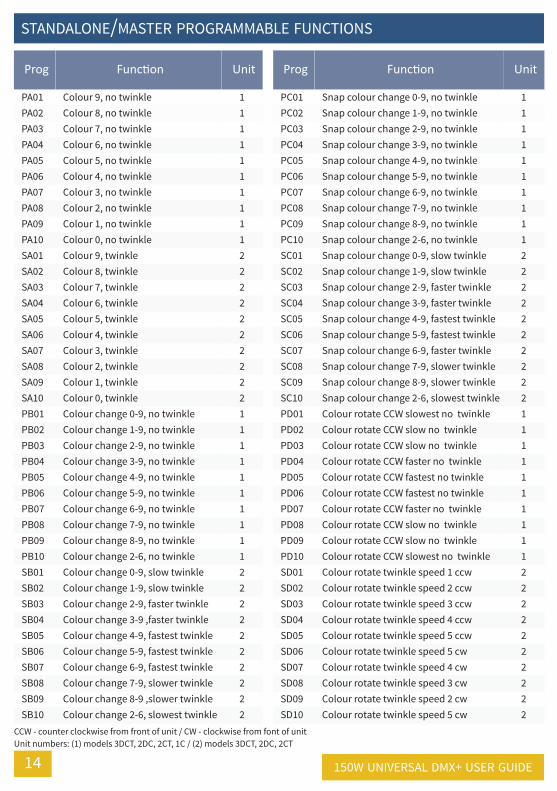
sTandalone/masTer ProGrammable FUncTions
14
Prog Function Unit
Pa01 colour 9, no twinkle 1Pa02 colour 8, no twinkle 1Pa03 colour 7, no twinkle 1Pa04 colour 6, no twinkle 1Pa05 colour 5, no twinkle 1Pa06 colour 4, no twinkle 1Pa07 colour 3, no twinkle 1Pa08 colour 2, no twinkle 1Pa09 colour 1, no twinkle 1Pa10 colour 0, no twinkle 1sa01 colour 9, twinkle 2sa02 colour 8, twinkle 2sa03 colour 7, twinkle 2sa04 colour 6, twinkle 2sa05 colour 5, twinkle 2sa06 colour 4, twinkle 2sa07 colour 3, twinkle 2sa08 colour 2, twinkle 2sa09 colour 1, twinkle 2sa10 colour 0, twinkle 2Pb01 colour change 0-9, no twinkle 1Pb02 colour change 1-9, no twinkle 1Pb03 colour change 2-9, no twinkle 1Pb04 colour change 3-9, no twinkle 1Pb05 colour change 4-9, no twinkle 1Pb06 colour change 5-9, no twinkle 1Pb07 colour change 6-9, no twinkle 1Pb08 colour change 7-9, no twinkle 1Pb09 colour change 8-9, no twinkle 1Pb10 colour change 2-6, no twinkle 1sb01 colour change 0-9, slow twinkle 2sb02 colour change 1-9, slow twinkle 2sb03 colour change 2-9, faster twinkle 2sb04 colour change 3-9 ,faster twinkle 2sb05 colour change 4-9, fastest twinkle 2sb06 colour change 5-9, fastest twinkle 2sb07 colour change 6-9, fastest twinkle 2sb08 colour change 7-9, slower twinkle 2sb09 colour change 8-9 ,slower twinkle 2sb10 colour change 2-6, slowest twinkle 2
Prog Function Unit
Pc01 snap colour change 0-9, no twinkle 1Pc02 snap colour change 1-9, no twinkle 1Pc03 snap colour change 2-9, no twinkle 1Pc04 snap colour change 3-9, no twinkle 1Pc05 snap colour change 4-9, no twinkle 1Pc06 snap colour change 5-9, no twinkle 1Pc07 snap colour change 6-9, no twinkle 1Pc08 snap colour change 7-9, no twinkle 1Pc09 snap colour change 8-9, no twinkle 1Pc10 snap colour change 2-6, no twinkle 1sc01 snap colour change 0-9, slow twinkle 2sc02 snap colour change 1-9, slow twinkle 2sc03 snap colour change 2-9, faster twinkle 2sc04 snap colour change 3-9, faster twinkle 2sc05 snap colour change 4-9, fastest twinkle 2sc06 snap colour change 5-9, fastest twinkle 2sc07 snap colour change 6-9, faster twinkle 2sc08 snap colour change 7-9, slower twinkle 2sc09 snap colour change 8-9, slower twinkle 2sc10 snap colour change 2-6, slowest twinkle 2Pd01 colour rotate ccw slowest no twinkle 1Pd02 colour rotate ccw slow no twinkle 1Pd03 colour rotate ccw slow no twinkle 1Pd04 colour rotate ccw faster no twinkle 1Pd05 colour rotate ccw fastest no twinkle 1Pd06 colour rotate ccw fastest no twinkle 1Pd07 colour rotate ccw faster no twinkle 1Pd08 colour rotate ccw slow no twinkle 1Pd09 colour rotate ccw slow no twinkle 1Pd10 colour rotate ccw slowest no twinkle 1sd01 colour rotate twinkle speed 1 ccw 2sd02 colour rotate twinkle speed 2 ccw 2sd03 colour rotate twinkle speed 3 ccw 2sd04 colour rotate twinkle speed 4 ccw 2sd05 colour rotate twinkle speed 5 ccw 2sd06 colour rotate twinkle speed 5 cw 2sd07 colour rotate twinkle speed 4 cw 2sd08 colour rotate twinkle speed 3 cw 2sd09 colour rotate twinkle speed 2 cw 2sd10 colour rotate twinkle speed 5 cw 2
ccw - counter clockwise from front of unit / cw - clockwise from font of unitUnit numbers: (1) models 3dcT, 2dc, 2cT, 1c / (2) models 3dcT, 2dc, 2cT
150w Universal dmX+ User GUide
15UFo liGhTinG
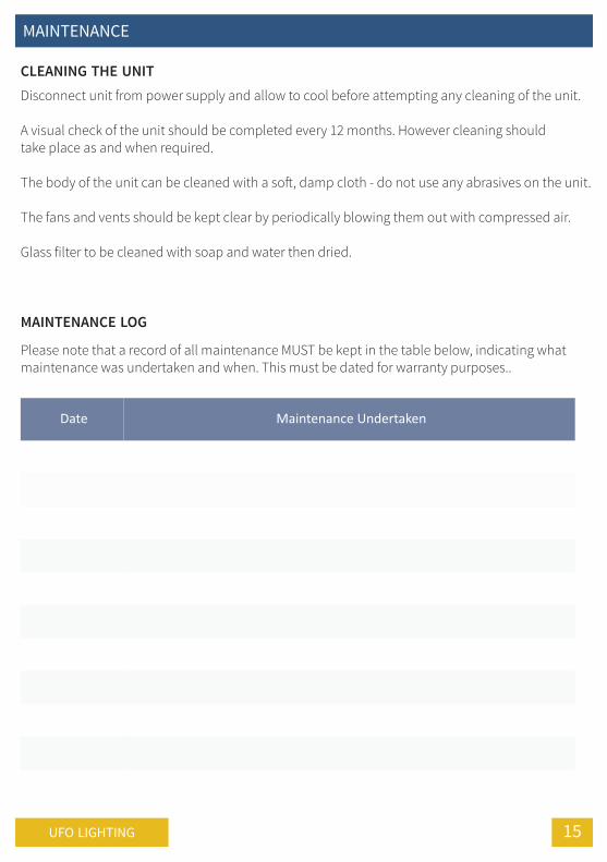
mainTenance
CLEANING THE UNITDisconnect unit from power supply and allow to cool before attempting any cleaning of the unit.
A visual check of the unit should be completed every 12 months. However cleaning shouldtake place as and when required.
The body of the unit can be cleaned with a soft, damp cloth - do not use any abrasives on the unit.
The fans and vents should be kept clear by periodically blowing them out with compressed air.
Glass filter to be cleaned with soap and water then dried.
Date Maintenance Undertaken
MAINTENANCE LOG
Please note that a record of all maintenance MUST be kept in the table below, indicating whatmaintenance was undertaken and when. This must be dated for warranty purposes..
mainTenenace
16
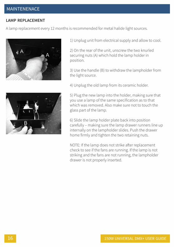
LAMP REPLACEMENT
A lamp replacement every 12 months is recommended for metal halide light sources.
1) Unplug unit from electrical supply and allow to cool.
2) On the rear of the unit, unscrew the two knurledsecuring nuts (A) which hold the lamp holder inposition.
3) Use the handle (B) to withdraw the lampholder fromthe light source.
4) Unplug the old lamp from its ceramic holder.
5) Plug the new lamp into the holder, making sure thatyou use a lamp of the same specification as to thatwhich was removed. Also make sure not to touch theglass part of the lamp.
6) Slide the lamp holder plate back into positioncarefully – making sure the lamp drawer runners line upinternally on the lampholder slides. Push the drawerhome firmly and tighten the two retaining nuts.
NOTE: If the lamp does not strike after replacementcheck to see if the fans are running. If the lamp is notstriking and the fans are not running, the lampholderdrawer is not properly inserted.
150w Universal dmX+ User GUide
17UFo liGhTinG
mainTenance
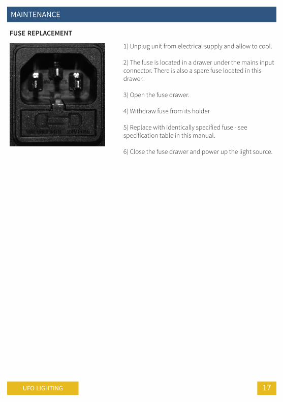
FUSE REPLACEMENT
1) Unplug unit from electrical supply and allow to cool.
2) The fuse is located in a drawer under the mains inputconnector. There is also a spare fuse located in thisdrawer.
3) Open the fuse drawer.
4) Withdraw fuse from its holder
5) Replace with identically specified fuse - seespecification table in this manual.
6) Close the fuse drawer and power up the light source.
TroUbleshooTinG
18 150w Universal dmX+ User GUide
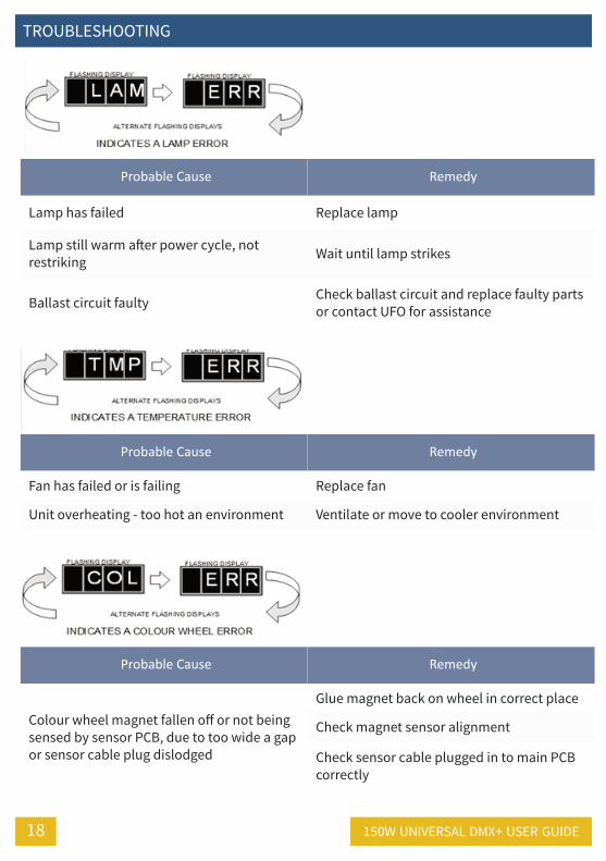
Probable Cause Remedy
lamp has failed replace lamp
lamp still warm after power cycle, notrestriking wait until lamp strikes
ballast circuit faulty check ballast circuit and replace faulty partsor contact UFo for assistance
Probable Cause Remedy
Fan has failed or is failing replace fan
Unit overheating - too hot an environment ventilate or move to cooler environment
Probable Cause Remedy
colour wheel magnet fallen off or not beingsensed by sensor Pcb, due to too wide a gapor sensor cable plug dislodged
Glue magnet back on wheel in correct place
check magnet sensor alignment
check sensor cable plugged in to main Pcbcorrectly
19UFo liGhTinG
TroUbleshooTinG
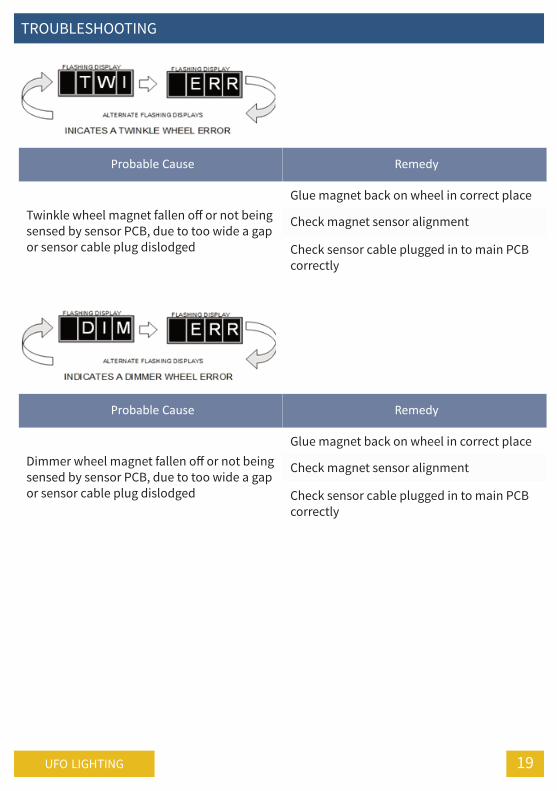
Probable Cause Remedy
Twinkle wheel magnet fallen off or not beingsensed by sensor Pcb, due to too wide a gapor sensor cable plug dislodged
Glue magnet back on wheel in correct place
check magnet sensor alignment
check sensor cable plugged in to main Pcbcorrectly
Probable Cause Remedy
dimmer wheel magnet fallen off or not beingsensed by sensor Pcb, due to too wide a gapor sensor cable plug dislodged
Glue magnet back on wheel in correct place
check magnet sensor alignment
check sensor cable plugged in to main Pcbcorrectly

TroUbleshooTinG
20 150w Universal dmX+ User GUide
Problem Probable cause(s) Remedy
Unit is completely dead - lampand neon power indicator arenot illuminated
main fuse blown check and replace fuse
no power ro unit check that power is switched on and psu isplugged in
led power indicator & fan areon, but no light is output
lamp blown replace lamp
Thermal switch activated allow unit to cool for 5 to 10 minutes andinvestigate reason for overheating
lamp wires are notconnected
check plug connection - ensure lamp is properlyseated in its holder and the pins are fully mated
Poor light output
lamp needs replacing replace lamp
Unit needs cleaning clean reflector and glass lens
incorrect power supply ensure power supply is 240vac 50hz
Fibre port connector notplugged in correctly
ensure fibre port connector is plugged incorrectly, and that the screw is tightened upproperly
lamp going on & off randomly Unit is overheating allow unit to cool for 5 to 10 minutes andinvestigate reason for overheating
lamp not striking & both fansnot running
lamp holder drawer on rear ofunit not pushed in fully
remove lamp holder drawer and reinsert,ensuring fully pushed hime and tightened up
Unit resets correctly but doesnot respond to controller
The controller is not connected connect the controller
reversed data signal polarity install a phase reversing cable between the unitand the controller
bad data link connection check cables and connections. repair or replacedamaged cables.
data link not terminated insert termination plug into output of the lastunit in the link
incorrect address setting check address setting
one of the units is transmittingas a master or is faulty
bypass one fixture at a time until normaloperation is regained
Unit does not reset correctly an effect requires mechanicaladjustment contact UFo for assistance
no light outputlamp too hot to strike allow lamp to cool
Faulty lamp check and replace lamp
lamp cuts out intermittently orburns out too quickly
Unit is too hot allow unit to cool
Faulty fan contact UFo for assistance
Unit freezes during dmX reset reset not correctly carried out recycle mains power off and on
21UFo liGhTinG
Technical sPeciFicaTions
Description
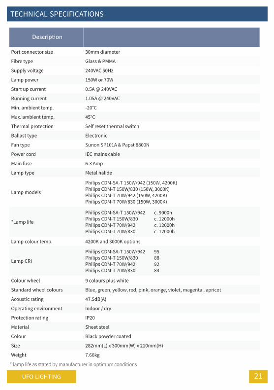
Port connector size 30mm diameter
Fibre type Glass & Pmma
supply voltage 240vac 50hz
lamp power 150w or 70w
start up current 0.5a @ 240vac
running current 1.05a @ 240vac
min. ambient temp. -20°c
max. ambient temp. 45°c
Thermal protection self reset thermal switch
ballast type electronic
Fan type sunon sP101a & Papst 8800n
Power cord iec mains cable
main fuse 6.3 amp
lamp type metal halide
lamp models
Philips cdm-sa-T 150w/942 (150w, 4200K)Philips cdm-T 150w/830 (150w, 3000K)Philips cdm-T 70w/942 (150w, 4200K)Philips cdm-T 70w/830 (150w, 3000K)
*lamp life
Philips cdm-sa-T 150w/942 c. 9000hPhilips cdm-T 150w/830 c. 12000hPhilips cdm-T 70w/942 c. 12000hPhilips cdm-T 70w/830 c. 12000h
lamp colour temp. 4200K and 3000K options
lamp cri
Philips cdm-sa-T 150w/942 95Philips cdm-T 150w/830 88Philips cdm-T 70w/942 92Philips cdm-T 70w/830 84
colour wheel 9 colours plus white
standard wheel colours blue, green, yellow, red, pink, orange, violet, magenta , apricot
acoustic rating 47.5db(a)
operating environment indoor / dry
Protection rating iP20
material sheet steel
colour black powder coated
size 282mm(l) x 300mm(w) x 210mm(h)
weight 7.66kg
* lamp life as stated by manufacturer in optimum conditions

noTes
22 150w Universal dmX+ User GUide

23UFo liGhTinG
noTes

desiGn sPeciFy bUild insTall
United Kingdom • United States • Germany • Europe • UAE
Universal Fibre Optics LtdHome PlaceColdstream, TD12 4DTUnited Kingdom
t. +44 (0)1890 883416www.ufo.lighting
Universal Fiber Optic lighting LLC6119A Clark Center AvenueSarasota, FL34238United States
t. +1 941-343-8115www.fiberopticlighting.com
Made in the United Kingdom
UFO Licht GmBHDas Runde Haue GBRGewerbering Ost 5b93155 Hemau, Deutschland
t. +49-(0)9491-95588-0www.ufo-licht.de