UFGS 22 05 48.00 20 Mechanical Sound, Vibration, and ... 22 05 48.00 20.pdfFor each piece of...
63
************************************************************************** USACE / NAVFAC / AFCEC / NASA UFGS-22 05 48.00 20 (April 2006) Change 1 - 05/15 -------------------------------- Preparing Activity: NAVFAC Replacing without change UFGS-15070N (September 1999) UNIFIED FACILITIES GUIDE SPECIFICATIONS References are in agreement with UMRL dated April 2018 ************************************************************************** SECTION TABLE OF CONTENTS DIVISION 22 - PLUMBING SECTION 22 05 48.00 20 MECHANICAL SOUND, VIBRATION, AND SEISMIC CONTROL 04/06 PART 1 GENERAL 1.1 REFERENCES 1.2 RELATED REQUIREMENTS 1.3 DEFINITIONS 1.3.1 Decibels dB 1.3.2 Machinery 1.3.3 Manufacturer 1.3.4 Micropascal uPa 1.3.5 Picowatt pW 1.4 SYSTEM DESCRIPTION 1.4.1 Spring Isolator Data 1.4.2 Machinery Manufacturer's Sound Data 1.4.3 Machinery 1.4.4 Machinery Over 136 Kilograms Machinery Over 300 Pounds 1.4.5 Machinery Vibration Criteria 1.4.6 Machinery Airborne Sound Level Criteria 1.4.6.1 Basic Criteria 1.4.6.2 Sound Data Schedule 1.4.7 Seismic Protection Criteria 1.4.8 Welding 1.5 SUBMITTALS 1.6 QUALITY ASSURANCE 1.6.1 Vibration Isolator Procurement 1.6.2 Unitized Machinery Assemblies PART 2 PRODUCTS 2.1 CORROSION PROTECTION FOR STEEL PARTS 2.2 NEOPRENE 2.3 FLOOR-MOUNTED ISOLATORS 2.3.1 Neoprene Isolation Pads 2.3.2 Neoprene Isolators 2.4 SPRING ISOLATORS AND PROTECTED SPRING ISOLATORS 2.4.1 Springs SECTION 22 05 48.00 20 Page 1
Transcript of UFGS 22 05 48.00 20 Mechanical Sound, Vibration, and ... 22 05 48.00 20.pdfFor each piece of...

**************************************************************************USACE / NAVFAC / AFCEC / NASA UFGS- 22 05 48. 00 20 ( Apr i l 2006) Change 1 - 05/ 15 - - - - - - - - - - - - - - - - - - - - - - - - - - - - - - - -Pr epar i ng Act i v i t y: NAVFAC Repl aci ng wi t hout change UFGS- 15070N ( Sept ember 1999)
UNI FI ED FACI LI TI ES GUI DE SPECI FI CATI ONS
Ref er ences ar e i n agr eement wi t h UMRL dat ed Apr i l 2018**************************************************************************
SECTI ON TABLE OF CONTENTS
DI VI SI ON 22 - PLUMBI NG
SECTI ON 22 05 48. 00 20
MECHANI CAL SOUND, VI BRATI ON, AND SEI SMI C CONTROL
04/06
PART 1 GENERAL
1. 1 REFERENCES 1. 2 RELATED REQUI REMENTS 1. 3 DEFI NI TI ONS 1. 3. 1 Deci bel s dB 1. 3. 2 Machi ner y 1. 3. 3 Manuf act ur er 1. 3. 4 Mi cr opascal uPa 1. 3. 5 Pi cowat t pW 1. 4 SYSTEM DESCRI PTI ON 1. 4. 1 Spr i ng I sol at or Dat a 1. 4. 2 Machi ner y Manuf act ur er ' s Sound Dat a 1. 4. 3 Machi ner y 1. 4. 4 Machi ner y Over 136 Ki l ogr ams Machi ner y Over 300 Pounds 1. 4. 5 Machi ner y Vi br at i on Cr i t er i a 1. 4. 6 Machi ner y Ai r bor ne Sound Level Cr i t er i a 1. 4. 6. 1 Basi c Cr i t er i a 1. 4. 6. 2 Sound Dat a Schedul e 1. 4. 7 Sei smi c Pr ot ect i on Cr i t er i a 1. 4. 8 Wel di ng 1. 5 SUBMI TTALS 1. 6 QUALI TY ASSURANCE 1. 6. 1 Vi br at i on I sol at or Pr ocur ement 1. 6. 2 Uni t i zed Machi ner y Assembl i es
PART 2 PRODUCTS
2. 1 CORROSI ON PROTECTI ON FOR STEEL PARTS 2. 2 NEOPRENE 2. 3 FLOOR- MOUNTED I SOLATORS 2. 3. 1 Neopr ene I sol at i on Pads 2. 3. 2 Neopr ene I sol at or s 2. 4 SPRI NG I SOLATORS AND PROTECTED SPRI NG I SOLATORS 2. 4. 1 Spr i ngs
SECTI ON 22 05 48. 00 20 Page 1

2. 4. 2 Mount i ng and Adj ust ment 2. 5 SUSPENSI ON I SOLATORS 2. 5. 1 Suspensi on Neopr ene I sol at or s 2. 5. 2 Suspensi on Spr i ng I sol at or s 2. 6 [ MACHI NERY BASES] [ , PLATFORMS] [ , RAI LS] [ SADDLES] 2. 7 I NERTI A BASES 2. 8 FLEXI BLE CONNECTORS FOR PI PI NG 2. 8. 1 El ast omer i c Fl exi bl e Connect or s 2. 8. 2 Met al Fl exi bl e Connect or s 2. 9 FLEXI BLE DUCT CONNECTORS 2. 10 SEI SMI C SNUBBERS FOR EQUI PMENT 2. 11 PI PE GUI DES 2. 12 THRUST RESTRAI NTS 2. 13 [ SEI SMI C PROTECTI ON COMPONENTS FOR [ PI PI NG] [ AND] [ DUCTWORK]
PART 3 EXECUTI ON
3. 1 I NSTALLATI ON 3. 1. 1 Vi br at i on and Noi se I sol at i on Component s 3. 1. 2 Suspensi on Vi br at i on I sol at or s 3. 1. 3 Ver t i cal St ops 3. 1. 4 Thr ust Rest r ai nt s 3. 1. 5 Fl exi bl e Pi pe and Duct Connect or s 3. 1. 6 Sei smi c Snubber s 3. 1. 7 Machi ner y 3. 1. 7. 1 St abi l i t y 3. 1. 7. 2 Lat er al Mot i on 3. 1. 7. 3 Unbal anced Machi ner y 3. 1. 7. 4 Nonr ot at i ng Machi ner y 3. 1. 7. 5 Uni t i zed Machi ner y Assembl i es 3. 1. 7. 6 Roof and Upper Fl oor Mount ed Machi ner y 3. 1. 8 [ Pi pi ng] [ and] [ Hi gh Pr essur e Duct wor k] 3. 1. 8. 1 Hi gh Pr essur e Duct wor k 3. 1. 8. 2 Pi pi ng Connect ed t o Vi br at i on I sol at ed Machi ner y 3. 1. 8. 3 St eam Pr essur e Reduci ng Val ves 3. 1. 8. 4 Condenser Wat er 3. 1. 8. 5 Chi l l ed, Hot , and Dual Temper at ur e Pi pi ng 3. 1. 9 Wat er and St eam Di st r i but i on Pi pi ng Appl i cat i on 3. 1. 10 Pi pe Hanger and Suppor t I nst al l at i on 3. 1. 10. 1 Pi pe Hanger s 3. 1. 10. 2 Hi gh Temper at ur es 3. 1. 10. 3 Val ves 3. 1. 10. 4 Machi ner y Wi t hout Fl exi bl e Connect i ons 3. 1. 10. 5 300 Mi l l i met er s Twel ve I nch and Lar ger Pi pe 3. 1. 10. 6 Pi pe Ri ser s 3. 1. 10. 7 Suppor t s at Base of Pi pe Ri ser s 3. 1. 10. 8 Pi pe Anchor s 3. 1. 11 Hi gh Pr essur e Duct wor k Hanger and Suppor t I nst al l at i on 3. 1. 11. 1 Duct Ri ser s 3. 1. 11. 2 Suppor t s at Base of Duct Ri ser s 3. 1. 11. 3 Duct Anchor s 3. 1. 12 Equi pment Room Sound I sol at i on 3. 1. 12. 1 Pi pe Penet r at i ons 3. 1. 12. 2 Duct Penet r at i ons 3. 1. 12. 3 Duct s Passi ng Thr ough Equi pment Rooms 3. 1. 13 Machi ner y Foundat i ons and Subbases 3. 1. 13. 1 Machi ner y Subbases 3. 1. 13. 2 Common Machi ner y Foundat i ons 3. 1. 13. 3 Foundat i on and Subbase Concr et e
SECTI ON 22 05 48. 00 20 Page 2

3. 1. 13. 4 Anchor Bol t s and Gr out 3. 1. 14 I ner t i a Bases 3. 1. 15 Sei smi c Rest r ai nt s f or [ Pi pi ng] [ and] [ Duct wor k] 3. 1. 16 Suspended Machi ner y Pl at f or ms 3. 1. 17 El ect r i cal Connect i ons 3. 1. 18 Syst ems Not To Be Vi br at i on I sol at ed 3. 2 FI ELD QUALI TY CONTROL 3. 2. 1 Fi el d I nspect i ons 3. 2. 2 Spr i ng I sol at or I nspect i on 3. 2. 3 Test s 3. 2. 3. 1 Equi pment Vi br at i on Test s 3. 2. 3. 2 Equi pment Sound Level Test s
- - End of Sect i on Tabl e of Cont ent s - -
SECTI ON 22 05 48. 00 20 Page 3
**************************************************************************USACE / NAVFAC / AFCEC / NASA UFGS- 22 05 48. 00 20 ( Apr i l 2006) Change 1 - 05/ 15 - - - - - - - - - - - - - - - - - - - - - - - - - - - - - - - -Pr epar i ng Act i v i t y: NAVFAC Repl aci ng wi t hout change UFGS- 15070N ( Sept ember 1999)
UNI FI ED FACI LI TI ES GUI DE SPECI FI CATI ONS
Ref er ences ar e i n agr eement wi t h UMRL dat ed Apr i l 2018**************************************************************************
SECTI ON 22 05 48. 00 20
MECHANI CAL SOUND, VI BRATI ON, AND SEI SMI C CONTROL04/06
**************************************************************************NOTE: Thi s gui de speci f i cat i on cover s t he r equi r ement s f or v i br at i on i sol at i on and sei smi c snubbi ng f or mechani cal and el ect r i cal equi pment .
Adher e t o UFC 1- 300- 02 Uni f i ed Faci l i t i es Gui de Speci f i cat i ons ( UFGS) For mat St andar d when edi t i ng t hi s gui de speci f i cat i on or pr epar i ng new pr oj ect speci f i cat i on sect i ons. Edi t t hi s gui de speci f i cat i on f or pr oj ect speci f i c r equi r ement s by addi ng, del et i ng, or r evi s i ng t ext . For br acket ed i t ems, choose appl i cabl e i t em( s) or i nser t appr opr i at e i nf or mat i on.
Remove i nf or mat i on and r equi r ement s not r equi r ed i n r espect i ve pr oj ect , whet her or not br acket s ar e present.
Comment s, suggest i ons and r ecommended changes f or t hi s gui de speci f i cat i on ar e wel come and shoul d be submi t t ed as a Cr i t er i a Change Request ( CCR) .
**************************************************************************
**************************************************************************NOTE: Thi s speci f i cat i on i ncl udes v i br at i on i sol at or s and st ops, sei smi c snubber s, machi ner y bases and t he i nst al l at i on, i nspect i on, and t est i ng of t he v i br at i on i sol at i on of machi ner y and syst ems.
**************************************************************************
**************************************************************************NOTE: The f ol l owi ng i nf or mat i on shal l be shown on t he pr oj ect dr awi ngs:
1. Ext ent of pi pi ng syst ems depi ct i ng i sol at i on hanger s on t he pi pi ng f l ow di agr am. Pi pe r i ser s havi ng l ow t her mal expansi on such as condenser and chi l l ed wat er l i nes may be i sol at ed f r om t he bui l di ng st r uct ur e by pr ovi di ng v i br at i on i sol at i on uni t s at t he base and i sol at i on gui des at f l oor s l abs t wo t o t hr ee st or i es apar t . Hot wat er syst ems
SECTI ON 22 05 48. 00 20 Page 4
r i ser s and si mi l ar pi pi ng havi ng hi gh t her mal expansi on wi l l gener al l y r equi r e one or mor e anchor s and expansi on j oi nt s t o obt ai n sat i sf act or y suppor t wi t h spr i ng i sol at i on hanger s.
2. Det ai l s of v i br at i on i sol at i on suppor t s and gui des not shown on dr awi ngs, such as col umn suppor t ed spr i ng i sol at or s f or cool i ng t ower s, and equi pment suppor t s and i sol at i on when equi pment i s l ocat ed on r oof s of l i ght const r uct i on.
3. Vi br at i on i sol at or s. I ndi cat e i n equi pment schedul e and det ai l s . I ndi cat e wher e v i br at i on i sol at i on i s t o be pr ovi ded f or pi pi ng and duct wor k. Det ai l i sol at or s onl y t o t he ext ent necessar y t o i ndi cat e t ype or i dent i f y t ypes i n not es or symbol l egend.
4. Fl exi bl e connect or s f or equi pment .
5. Fl exi bl e duct connect or s.
6. Sei smi c snubber s. I ndi cat e i n equi pment schedul es and det ai l s . When speci f i ed as an opt i on det ai l shop f abr i cat ed sei smi c snubber s.
7. Sei smi c sway br aci ng and cabl es f or pi pi ng and ductwork.
8. Fl exi bl e connect or s f or pi pi ng and duct wor k. I ndi cat e t ypes.
9. Equi pment bases, r ai l s , and saddl es.
10. I ner t i a bases.
11. Anchor bol t s. I ndi cat e s i zes i n equi pment schedul es or det ai l s f or r i gi dl y f i xed machi ner y.
12. Suspended equi pment pl at f or ms. I ndi cat e v i br at i on i sol at or det ai l s .
13. Pi pe gui des.
14. Equi pment dat a. I ndi cat e or speci f y equi pment r pm vi br at i on ampl i t udes and f or ces, maxi mum noi se l evel s, wei ght , di mensi ons, and power maxi mum and mi ni mum l i mi t s, and st at i c and dynami c bal anci ng of requirements.
15. Sound dat a Schedul e. I ndi cat e t he maxi mum ai r bor ne sound power or sound pr essur e l evel s f or each machi ner y. I ndi cat e t he di st ance f r om t he sound sour ce ( i n case of sound power dat a) or measur ement l ocat i on ( i n case of sound pr essur e dat a) t o t he t ypi cal st at i on.
**************************************************************************
SECTI ON 22 05 48. 00 20 Page 5

PART 1 GENERAL
1. 1 REFERENCES
**************************************************************************NOTE: Thi s par agr aph i s used t o l i s t t he publ i cat i ons c i t ed i n t he t ext of t he gui de speci f i cat i on. The publ i cat i ons ar e r ef er r ed t o i n t he t ext by basi c desi gnat i on onl y and l i s t ed i n t hi s par agr aph by or gani zat i on, desi gnat i on, dat e, and t i t l e. Use t he Ref er ence Wi zar d' s Check Ref er ence f eat ur e when you add a Ref er ence I dent i f i er ( RI D) out s i de of t he Sect i on' s Ref er ence Ar t i c l e t o aut omat i cal l y pl ace t he r ef er ence i n t he Ref er ence Ar t i c l e. Al so use t he Ref er ence Wi zar d' s Check Ref er ence f eat ur e t o updat e t he i ssue dat es. Ref er ences not used i n t he t ext wi l l aut omat i cal l y be del et ed f r om t hi s sect i on of t he pr oj ect speci f i cat i on when you choose t o r econci l e r ef er ences i n t he publ i sh pr i nt pr ocess.
**************************************************************************
The publ i cat i ons l i s t ed bel ow f or m a par t of t hi s speci f i cat i on t o t he ext ent r ef er enced. The publ i cat i ons ar e r ef er r ed t o wi t hi n t he t ext by t he basi c desi gnat i on onl y.
AI R- CONDI TI ONI NG, HEATI NG AND REFRI GERATI ON I NSTI TUTE ( AHRI )
AHRI 575 ( 2008) Met hod of Measur i ng Machi ner y Sound Wi t hi n an Equi pment Space
ANSI / AHRI 370 ( 2015; Addendum 1 2016) Sound Rat i ng of Lar ge Out door Ref r i ger at i ng and Ai r - Condi t i oni ng Equi pment
AMERI CAN I NSTI TUTE OF STEEL CONSTRUCTI ON ( AI SC)
AI SC 360 ( 2016) Speci f i cat i on f or St r uct ur al St eel Buildings
AMERI CAN WELDI NG SOCI ETY ( AWS)
AWS D1. 1/ D1. 1M ( 2015; Er r at a 1 2015; Er r at a 2 2016) St r uct ur al Wel di ng Code - St eel
ASTM I NTERNATI ONAL ( ASTM)
ASTM A123/ A123M ( 2017) St andar d Speci f i cat i on f or Zi nc ( Hot - Di p Gal vani zed) Coat i ngs on I r on and St eel Pr oduct s
ASTM A36/ A36M ( 2014) St andar d Speci f i cat i on f or Car bon St r uct ur al St eel
ASTM A653/ A653M ( 2017) St andar d Speci f i cat i on f or St eel Sheet , Zi nc- Coat ed ( Gal vani zed) or
SECTI ON 22 05 48. 00 20 Page 6

Zi nc- I r on Al l oy- Coat ed ( Gal vanneal ed) by t he Hot - Di p Pr ocess
ASTM C94/ C94M ( 2017a) St andar d Speci f i cat i on f or Ready- Mi xed Concr et e
ASTM D2240 ( 2015; E 2017) St andar d Test Met hod f or Rubber Pr oper t y - Dur omet er Har dness
ASTM D471 ( 2016a) St andar d Test Met hod f or Rubber Pr oper t y - Ef f ect of Li qui ds
ASTM E84 ( 2018) St andar d Test Met hod f or Sur f ace Bur ni ng Char act er i st i cs of Bui l di ng Materials
SHEET METAL AND AI R CONDI TI ONI NG CONTRACTORS' NATI ONAL ASSOCI ATI ON (SMACNA)
SMACNA 1403 ( 2008) Accept ed I ndust r y Pr act i ce f or I ndust r i al Duct Const r uct i on, 2nd Edi t i on
SMACNA 1793 ( 2012) Ar chi t ect ur al Sheet Met al Manual , 7t h Edi t i on
SMACNA 1966 ( 2005) HVAC Duct Const r uct i on St andar ds Met al and Fl exi bl e, 3r d Edi t i on
SMACNA 1981 ( 2008) Sei smi c Rest r ai nt Manual Gui del i nes f or Mechani cal Syst ems, 3r d Edi t i on
1. 2 RELATED REQUI REMENTS
The pr ovi s i ons of Sect i on 23 03 00. 00 20 BASI C MECHANI CAL MATERI ALS AND METHODS appl y t o t hi s sect i on.
1. 3 DEFINITIONS
1. 3. 1 Deci bel s dB
Measur e of sound l evel . Deci bel s ar e r ef er enced t o ei t her 20 uPa f or sound pr essur e l evel s or one pW f or sound power l evel s. dBA i s t he over al l " A" wei ght ed sound l evel .
1. 3. 2 Machinery
The vi br at i on or noi se pr oduci ng equi pment t hat must be i sol at ed.
1. 3. 3 Manufacturer
The f abr i cat or or suppl i er of v i br at i on- i sol at i on or sei smi c- pr ot ect i on mat er i al s and equi pment . For mechani cal equi pment and machi ner y t he t er m machi ner y manuf act ur er wi l l be used.
1. 3. 4 Mi cr opascal uPa
10 t o t he mi nus 6 power newt ons per squar e met er .
SECTI ON 22 05 48. 00 20 Page 7
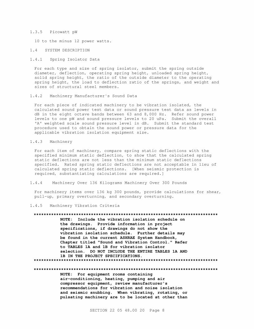
1. 3. 5 Pi cowat t pW
10 t o t he mi nus 12 power wat t s.
1. 4 SYSTEM DESCRI PTI ON
1. 4. 1 Spr i ng I sol at or Dat a
For each t ype and si ze of spr i ng i sol at or , submi t t he spr i ng out s i de di amet er , def l ect i on, oper at i ng spr i ng hei ght , unl oaded spr i ng hei ght , sol i d spr i ng hei ght , t he r at i o of t he out s i de di amet er t o t he oper at i ng spr i ng hei ght , t he l oad t o def l ect i on r at i o of t he spr i ngs, and wei ght and si zes of st r uct ur al st eel member s.
1. 4. 2 Machi ner y Manuf act ur er ' s Sound Dat a
For each pi ece of i ndi cat ed machi ner y t o be v i br at i on i sol at ed, t he cal cul at ed sound power t est dat a or sound pr essur e t est dat a as l evel s i n dB i n t he ei ght oct ave bands bet ween 63 and 8, 000 Hz. Ref er sound power l evel s t o one pW and sound pr essur e l evel s t o 20 uPa. Submi t t he over al l " A" wei ght ed scal e sound pr essur e l evel i n dB. Submi t t he st andar d t est pr ocedur e used t o obt ai n t he sound power or pr essur e dat a f or t he appl i cabl e v i br at i on i sol at i on equi pment s i ze.
1. 4. 3 Machinery
For each i t em of machi ner y, compar e spr i ng st at i c def l ect i ons wi t h t he speci f i ed mi ni mum st at i c def l ect i on, t o show t hat t he cal cul at ed spr i ng st at i c def l ect i ons ar e not l ess t han t he mi ni mum st at i c def l ect i ons speci f i ed. Rat ed spr i ng st at i c def l ect i ons ar e not accept abl e i n l i eu of cal cul at ed spr i ng st at i c def l ect i ons. [ When sei smi c pr ot ect i on i s r equi r ed, subst ant i at i ng cal cul at i ons ar e r equi r ed. ]
1. 4. 4 Machi ner y Over 136 Ki l ogr ams Machi ner y Over 300 Pounds
For machi ner y i t ems over 136 kg 300 pounds, pr ovi de cal cul at i ons f or shear , pul l - up, pr i mar y over t ur ni ng, and secondar y over t ur ni ng.
1. 4. 5 Machi ner y Vi br at i on Cr i t er i a
**************************************************************************NOTE: I ncl ude t he v i br at i on i sol at i on schedul e on t he dr awi ngs. Pr ovi de i nf or mat i on i n pr oj ect speci f i cat i ons, i f dr awi ngs do not show t he v i br at i on i sol at i on schedul e. Fur t her det ai l s may be f ound i n t he cur r ent ASHRAE Syst em Handbook, Chapt er t i t l ed " Sound and Vi br at i on Cont r ol . " Ref er t o TABLES 1A and 1B f or v i br at i on i sol at or sel ect i on. DO NOT I NCLUDE THE ENTI RE TABLES 1A AND 1B I N THE PROJECT SPECI FI CATI ONS.
**************************************************************************
**************************************************************************NOTE: For equi pment r ooms cont ai ni ng ai r - condi t i oni ng, heat i ng, pumpi ng and ai r compr essor equi pment , r evi ew manuf act ur er ' s r ecommendat i ons f or v i br at i on and noi se i sol at i on and sei smi c snubbi ng. When vi br at i ng, r ot at i ng, or pul sat i ng machi ner y ar e t o be l ocat ed at ot her t han
SECTI ON 22 05 48. 00 20 Page 8

on gr ade, coor di nat e wi t h t he st r uct ur al desi gner t o avoi d pr obl ems caused by machi ner y i nduced vi br at i ons i n t he bui l di ng st r uct ur e. For heavy v i br at i ng machi ner y l ocat ed anywher e, compl et el y r evi ew vi br at i on i sol at i on r equi r ement s. Coor di nat e wi t h t he desi gner about t he maxi mum al l owabl e l evel s of sound and vi br at i on i n equi pment l ocat i ons. Ref er t o bot h t he Appl i cabl e Publ i cat i ons and t he f ol l owi ng publ i cat i ons f or gui dance i n sound, v i br at i on i sol at i on, and sei smi c r est r ai nt devi ces f or mechani cal equi pment and syst ems:
I NTERNATI ONAL CODE COUNCI L ( I CC)
UFC 3- 310- 04, " Sei smi c Desi gn of Bui l di ngs" .**************************************************************************
**************************************************************************NOTE: The f ol l owi ng t abl e ser ves onl y as a gui del i ne. Del et e i t ems t hat ar e not appl i cabl e.
**************************************************************************
TABLE 1A
Vi br at i on I sol at or Types and Mi ni mum St at i c Def l ect i on
( MSD, mm) f or 100- 200 mm sl ab on gr ade and col umn suppor t ed.
ColumnSpacing
Sl ab on ear t h and 0- 9meter
9. 1- 12 met er s 12. 1- 15 met er s
Equipment Type ( Not e (1))
MSD ( Not e (1))
Type ( Not e (1))
MSD ( Not e (1))
Type ( Not e (1))
MSD ( Not e (1))
Absorption Refrigeration Machines
SV-R 25.40 SV-R 44.45 SV-R 69.85
Cent r i f ugal Chi l l er s or Heat Pumps
Hermetic Type
SV-B 44.45 SV-B 63.50 SV-B 88.90
Open Type SV-1 44.45 SV-I 63.50 SV-I 88.90
Reci pr ocat i ng Ai r or Ref r i ger at i on Compr essor s
SECTI ON 22 05 48. 00 20 Page 9

TABLE 1A
Vi br at i on I sol at or Types and Mi ni mum St at i c Def l ect i on
( MSD, mm) f or 100- 200 mm sl ab on gr ade and col umn suppor t ed.
ColumnSpacing
Sl ab on ear t h and 0- 9meter
9. 1- 12 met er s 12. 1- 15 met er s
Equipment Type ( Not e (1))
MSD ( Not e (1))
Type ( Not e (1))
MSD ( Not e (1))
Type ( Not e (1))
MSD ( Not e (1))
500 t o 750 rpm
S-R 44.45 S-R 63.50 S-R 88.90
751 r pm and up
S-R 38.10 S-R 63.50 S-R 88.90
Reci pr ocat i ng Chi l l er s or Heat Pumps
500 t o 750 rpm
SV-R 44.45 SV-R 63.50 SV-R 88.90
751 r pm and up
SV-R 38.10 SV-R 63.50 SV-R 88.90
Packaged Boilers
SV 25.40 SV 63.50 SV-R 88.90
Cl osed Coupl ed Pumps
Up t o 5 1/ 2 kW
S-I 25.40 S-I 25.40 S-I 25.40
Over 5 1/ 2 kW
S-I 38.10 S-I 63.50 S-I 63.50
Base Mount ed Pumps
Up t o 15 kW S-I 38.10 S-I 63.50 S-I 63.50
15 t o 56 kW S-I 38.10 S-I 63.50 S-I 88.90
Over 56 kW S-I 63.50 S-I 88.90 S-I 88.90
Cool i ng Tower s and Evapor at i ve Condenser s
SV wi t h def l ect i ons speci f i ed f or cent r i f ugal bl ower s when spr i ngs ar e suppor t ed on beams. Use def l ect i on l i s t ed f or col umn suppor t ed f l oor s wi t h up t o 9 met er s col umn spaci ng when spr i ngs ar e l ocat ed on col umns or bear i ng wal l s.
SECTI ON 22 05 48. 00 20 Page 10
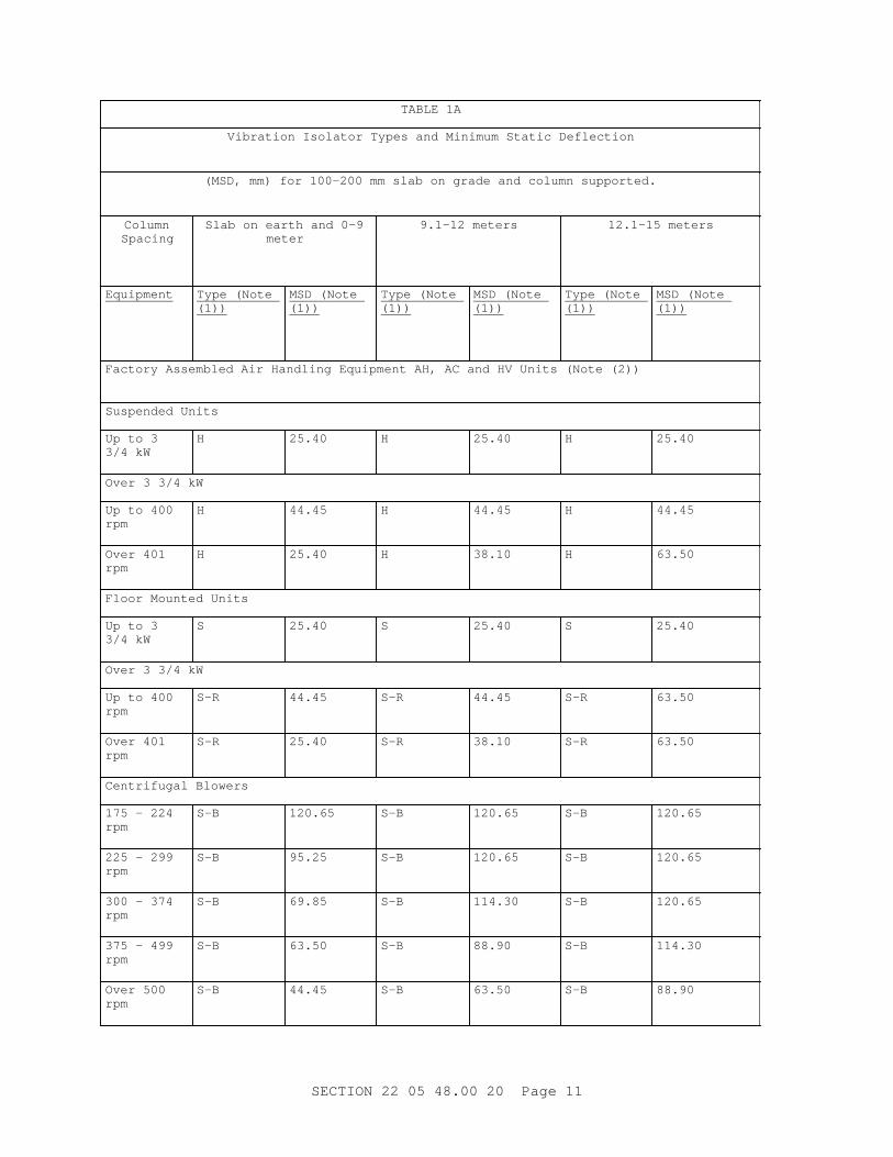
TABLE 1A
Vi br at i on I sol at or Types and Mi ni mum St at i c Def l ect i on
( MSD, mm) f or 100- 200 mm sl ab on gr ade and col umn suppor t ed.
ColumnSpacing
Sl ab on ear t h and 0- 9meter
9. 1- 12 met er s 12. 1- 15 met er s
Equipment Type ( Not e (1))
MSD ( Not e (1))
Type ( Not e (1))
MSD ( Not e (1))
Type ( Not e (1))
MSD ( Not e (1))
Fact or y Assembl ed Ai r Handl i ng Equi pment AH, AC and HV Uni t s ( Not e ( 2) )
Suspended Uni t s
Up t o 3 3/ 4 kW
H 25.40 H 25.40 H 25.40
Over 3 3/ 4 kW
Up t o 400 rpm
H 44.45 H 44.45 H 44.45
Over 401 rpm
H 25.40 H 38.10 H 63.50
Fl oor Mount ed Uni t s
Up t o 3 3/ 4 kW
S 25.40 S 25.40 S 25.40
Over 3 3/ 4 kW
Up t o 400 rpm
S-R 44.45 S-R 44.45 S-R 63.50
Over 401 rpm
S-R 25.40 S-R 38.10 S-R 63.50
Cent r i f ugal Bl ower s
175 - 224 rpm
S-B 120.65 S-B 120.65 S-B 120.65
225 - 299 rpm
S-B 95.25 S-B 120.65 S-B 120.65
300 - 374 rpm
S-B 69.85 S-B 114.30 S-B 120.65
375 - 499 rpm
S-B 63.50 S-B 88.90 S-B 114.30
Over 500 rpm
S-B 44.45 S-B 63.50 S-B 88.90
SECTI ON 22 05 48. 00 20 Page 11

TABLE 1A
Vi br at i on I sol at or Types and Mi ni mum St at i c Def l ect i on
( MSD, mm) f or 100- 200 mm sl ab on gr ade and col umn suppor t ed.
ColumnSpacing
Sl ab on ear t h and 0- 9meter
9. 1- 12 met er s 12. 1- 15 met er s
Equipment Type ( Not e (1))
MSD ( Not e (1))
Type ( Not e (1))
MSD ( Not e (1))
Type ( Not e (1))
MSD ( Not e (1))
Tubul ar Cent r i f ugal and Axi al Fans ( Not e ( 2) )
Suspended H wi t h def l ect i on speci f i ed f or cent r i f ugal bl ower s
Fl oor Mount ed Ar r angement s 1 & 9
S- B wi t h def l ect i ons speci f i ed f or cent r i f ugal bl ower s
Ut i l i t y Fans ( Not e ( 2) )
Suspended H wi t h def l ect i ons speci f i ed f or cent r i f ugal bl ower s but not t o exceed 69. 85 mm
Floor-Mounted S- R wi t h def l ect i ons not speci f i ed f or cent r i f ugal bl ower s but not t o exceed 69. 85 mm
Hi gh Pr essur e Fans ( Over 1494 Pa St at i c Pr essur e) and Ot her Machi ner i es Pr oduci ng Thr ust ( Not e ( 2) )
HR r ecommended f or mi ni mi zi ng undesi r abl e t hr ust ef f ect s
I nt er nal Combust i on Engi nes and Engi ne Dr i ven Equi p
750 r pm and over
S 38.10 S 63.50 S 88.90
Di mmer Banks and Tr ansf or mer s
Up t o 454 kg
NM 8.89 NM 8.89 NM 88.90
Over 454 kg SV 25.40 SV 25.40 SV 25.40
NOTES:
( 1) Equi pment Vi br at i on I sol at i on Schedul e Desi gnat i ons ( Hyphenat ed desi gnat i ons ar e combi nat i ons of t he f ol l owi ng: )
B - Wel ded st r uct ur al st eel bases.
SECTI ON 22 05 48. 00 20 Page 12
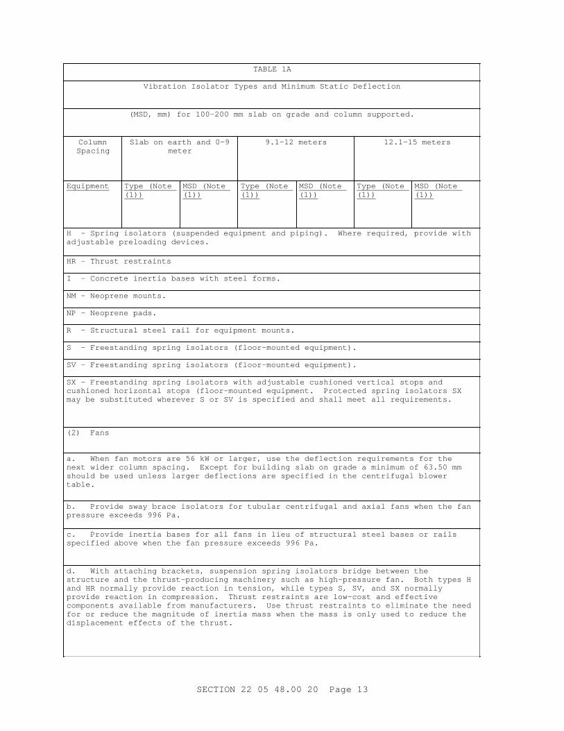
TABLE 1A
Vi br at i on I sol at or Types and Mi ni mum St at i c Def l ect i on
( MSD, mm) f or 100- 200 mm sl ab on gr ade and col umn suppor t ed.
ColumnSpacing
Sl ab on ear t h and 0- 9meter
9. 1- 12 met er s 12. 1- 15 met er s
Equipment Type ( Not e (1))
MSD ( Not e (1))
Type ( Not e (1))
MSD ( Not e (1))
Type ( Not e (1))
MSD ( Not e (1))
H - Spr i ng i sol at or s ( suspended equi pment and pi pi ng) . Wher e r equi r ed, pr ovi de wi t h adj ust abl e pr el oadi ng devi ces.
HR - Thr ust r est r ai nt s
I - Concr et e i ner t i a bases wi t h st eel f or ms.
NM - Neopr ene mount s.
NP - Neopr ene pads.
R - St r uct ur al st eel r ai l f or equi pment mount s.
S - Fr eest andi ng spr i ng i sol at or s ( f l oor - mount ed equi pment ) .
SV - Fr eest andi ng spr i ng i sol at or s ( f l oor - mount ed equi pment ) .
SX - Fr eest andi ng spr i ng i sol at or s wi t h adj ust abl e cushi oned ver t i cal st ops and cushi oned hor i zont al st ops ( f l oor - mount ed equi pment . Pr ot ect ed spr i ng i sol at or s SX may be subst i t ut ed wher ever S or SV i s speci f i ed and shal l meet al l r equi r ement s.
( 2) Fans
a. When f an mot or s ar e 56 kW or l ar ger , use t he def l ect i on r equi r ement s f or t he next wi der col umn spaci ng. Except f or bui l di ng sl ab on gr ade a mi ni mum of 63. 50 mm shoul d be used unl ess l ar ger def l ect i ons ar e speci f i ed i n t he cent r i f ugal bl ower table.
b. Pr ovi de sway br ace i sol at or s f or t ubul ar cent r i f ugal and axi al f ans when t he f an pr essur e exceeds 996 Pa.
c. Pr ovi de i ner t i a bases f or al l f ans i n l i eu of st r uct ur al st eel bases or r ai l s speci f i ed above when t he f an pr essur e exceeds 996 Pa.
d. Wi t h at t achi ng br acket s, suspensi on spr i ng i sol at or s br i dge bet ween t he st r uct ur e and t he t hr ust - pr oduci ng machi ner y such as hi gh- pr essur e f an. Bot h t ypes H and HR nor mal l y pr ovi de r eact i on i n t ensi on, whi l e t ypes S, SV, and SX nor mal l y pr ovi de r eact i on i n compr essi on. Thr ust r est r ai nt s ar e l ow- cost and ef f ect i ve component s avai l abl e f r om manuf act ur er s. Use t hr ust r est r ai nt s t o el i mi nat e t he need f or or r educe t he magni t ude of i ner t i a mass when t he mass i s onl y used t o r educe t he di spl acement ef f ect s of t he t hr ust .
SECTI ON 22 05 48. 00 20 Page 13

TABLE 1A
Vi br at i on I sol at or Types and Mi ni mum St at i c Def l ect i on
( MSD, i nches) f or 4- 8 i nch sl ab on gr ade and col umn suppor t ed.
Col umn Spaci ng Sl ab on ear t h and0- 30 f eet
31- 40 f eet 41- 50 f eet
Equipment Type ( Not e ( 1) )
MSD ( Not e (1))
Type ( Not e ( 1) )
MSD ( Not e (1))
Type ( Not e ( 1) )
MSD ( Not e (1))
Absorption Refrigeration Machines
SV-R 1.0 SV-R 1.75 SV-R 2.75
Cent r i f ugal Chi l l er s or Heat Pumps
Her met i c Type SV-B 1.75 SV-B 2.5 SV-B 3.5
Open Type SV-1 1.75 SV-I 2.5 SV-I 3.5
Reci pr ocat i ng Ai r or Ref r i ger at i on Compr essor s
500 t o 750 r pm S-R 1.75 S-R 2.5 S-R 3.5
751 r pm and up S-R 1.5 S-R 2.5 S-R 3.5
Reci pr ocat i ng Chi l l er s or Heat Pumps
500 t o 750 r pm SV-R 1.75 SV-R 2.5 SV-R 3.5
751 r pm and up SV-R 1.5 SV-R 2.5 SV-R 3.5
Packaged Boi l er s SV 1.0 SV 2.5 SV-R 3.5
Cl osed Coupl ed Pumps
Up t o 7- 1/ 2 hp S-I 1.0 S-I 1.0 S-I 1.0
Over 7- 1/ 2 hp S-I 1.5 S-I 2.5 S-I 2.5
SECTI ON 22 05 48. 00 20 Page 14

TABLE 1A
Vi br at i on I sol at or Types and Mi ni mum St at i c Def l ect i on
( MSD, i nches) f or 4- 8 i nch sl ab on gr ade and col umn suppor t ed.
Col umn Spaci ng Sl ab on ear t h and0- 30 f eet
31- 40 f eet 41- 50 f eet
Equipment Type ( Not e ( 1) )
MSD ( Not e (1))
Type ( Not e ( 1) )
MSD ( Not e (1))
Type ( Not e ( 1) )
MSD ( Not e (1))
Base Mount ed Pumps
Up t o 20 hp S-I 1.5 S-I 2.5 S-I 2.5
20 t o 75 hp S-I 1.5 S-I 2.5 S-I 3.5
Over 75 hp S-I 2.5 S-I 3.5 S-I 3.5
Cool i ng Tower s and Evapor at i ve Condenser s
SV wi t h def l ect i ons speci f i ed f or cent r i f ugal bl ower s when spr i ngs ar e suppor t ed on beams. Use sel ect i on l i s t ed f or col umn suppor t ed f l oor s wi t h up t o 30 f oot col umn spaci ng when spr i ngs ar e l ocat ed on col umns or bear i ng wal l s.
Fact or y Assembl ed Ai r Handl i ng Equi pment AH, AC and HV Uni t s ( Not e ( 2) )
Suspended Uni t s
Up t o 5 hp H 1.0 H 1.0 H 1.0
Over 5 hp
Up t o 400 r pm H 1.75 H 1.75 H 1.75
Over 401 r pm H 1.0 H 1.5 H 2.5
Fl oor Mount ed Uni t s
Up t o 5 hp S 1.0 S 1.0 S 1.0
Over 5 hp
Up t o 400 r pm S-R 1.75 S-R 1.75 S-R 2.5
Over 401 r pm S-R 1.0 S-R 1.5 S-R 2.5
SECTI ON 22 05 48. 00 20 Page 15
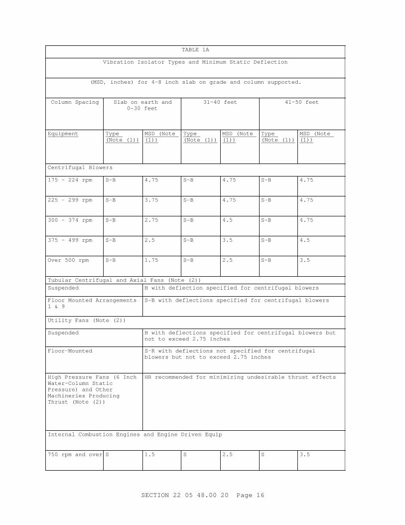
TABLE 1A
Vi br at i on I sol at or Types and Mi ni mum St at i c Def l ect i on
( MSD, i nches) f or 4- 8 i nch sl ab on gr ade and col umn suppor t ed.
Col umn Spaci ng Sl ab on ear t h and0- 30 f eet
31- 40 f eet 41- 50 f eet
Equipment Type ( Not e ( 1) )
MSD ( Not e (1))
Type ( Not e ( 1) )
MSD ( Not e (1))
Type ( Not e ( 1) )
MSD ( Not e (1))
Cent r i f ugal Bl ower s
175 - 224 r pm S-B 4.75 S-B 4.75 S-B 4.75
225 - 299 r pm S-B 3.75 S-B 4.75 S-B 4.75
300 - 374 r pm S-B 2.75 S-B 4.5 S-B 4.75
375 - 499 r pm S-B 2.5 S-B 3.5 S-B 4.5
Over 500 r pm S-B 1.75 S-B 2.5 S-B 3.5
Tubul ar Cent r i f ugal and Axi al Fans ( Not e ( 2) )
Suspended H wi t h def l ect i on speci f i ed f or cent r i f ugal bl ower s
Fl oor Mount ed Ar r angement s 1 & 9
S- B wi t h def l ect i ons speci f i ed f or cent r i f ugal bl ower s
Ut i l i t y Fans ( Not e ( 2) )
Suspended H wi t h def l ect i ons speci f i ed f or cent r i f ugal bl ower s but not t o exceed 2. 75 i nches
Floor-Mounted S- R wi t h def l ect i ons not speci f i ed f or cent r i f ugal bl ower s but not t o exceed 2. 75 i nches
Hi gh Pr essur e Fans ( 6 I nch Wat er - Col umn St at i c Pr essur e) and Ot her Machi ner i es Pr oduci ng Thr ust ( Not e ( 2) )
HR r ecommended f or mi ni mi zi ng undesi r abl e t hr ust ef f ect s
I nt er nal Combust i on Engi nes and Engi ne Dr i ven Equi p
750 r pm and over S 1.5 S 2.5 S 3.5
SECTI ON 22 05 48. 00 20 Page 16

TABLE 1A
Vi br at i on I sol at or Types and Mi ni mum St at i c Def l ect i on
( MSD, i nches) f or 4- 8 i nch sl ab on gr ade and col umn suppor t ed.
Col umn Spaci ng Sl ab on ear t h and0- 30 f eet
31- 40 f eet 41- 50 f eet
Equipment Type ( Not e ( 1) )
MSD ( Not e (1))
Type ( Not e ( 1) )
MSD ( Not e (1))
Type ( Not e ( 1) )
MSD ( Not e (1))
Di mmer Banks and Tr ansf or mer s
Up t o 1000 l bs. NM 0.35 NM 0.35 NM 3.5
Over 1000 l bs. SV 1.0 SV 1.0 SV 1.0
NOTES:
( 1) Equi pment Vi br at i on I sol at i on Schedul e Desi gnat i ons ( Hyphenat ed desi gnat i ons ar e combi nat i ons of t he f ol l owi ng: )
B - Wel ded st r uct ur al st eel bases.
H - Spr i ng i sol at or s ( suspended equi pment and pi pi ng) . Wher e r equi r ed, pr ovi de wi t h adj ust abl e pr el oadi ng devi ces.
HR - Thr ust r est r ai nt s
I - Concr et e i ner t i a bases wi t h st eel f or ms.
NM - Neopr ene mount s.
NP - Neopr ene pads.
R - St r uct ur al st eel r ai l f or equi pment mount s.
S - Fr eest andi ng spr i ng i sol at or s ( f l oor - mount ed equi pment ) .
SV - Fr eest andi ng spr i ng i sol at or s ( f l oor - mount ed equi pment ) .
SX - Fr eest andi ng spr i ng i sol at or s wi t h adj ust abl e cushi oned ver t i cal st ops and cushi oned hor i zont al st ops ( f l oor - mount ed equi pment . Pr ot ect ed spr i ng i sol at or s SX may be subst i t ut ed wher ever S or SV i s speci f i ed and shal l meet al l r equi r ement s.
( 2) Fans
a. When f an mot or s ar e 75 hp or l ar ger , use t he def l ect i on r equi r ement s f or t he next wi der col umn spaci ng. Except f or bui l di ng sl ab on gr ade a mi ni mum of 2. 5 i nches shoul d be used unl ess l ar ger def l ect i ons ar e speci f i ed i n t he cent r i f ugal bl ower table.
SECTI ON 22 05 48. 00 20 Page 17

TABLE 1A
Vi br at i on I sol at or Types and Mi ni mum St at i c Def l ect i on
( MSD, i nches) f or 4- 8 i nch sl ab on gr ade and col umn suppor t ed.
Col umn Spaci ng Sl ab on ear t h and0- 30 f eet
31- 40 f eet 41- 50 f eet
Equipment Type ( Not e ( 1) )
MSD ( Not e (1))
Type ( Not e ( 1) )
MSD ( Not e (1))
Type ( Not e ( 1) )
MSD ( Not e (1))
b. Pr ovi de sway br ace i sol at or s f or t ubul ar cent r i f ugal and axi al f ans when t he f an pr essur e exceeds 4 i nches wat er col umn.
c. Pr ovi de i ner t i a bases f or al l f ans i n l i eu of st r uct ur al st eel bases or r ai l s speci f i ed above when t he f an pr essur e exceeds 4 i nches wat er col umn.
d. Wi t h at t achi ng br acket s, suspensi on spr i ng i sol at or s br i dge bet ween t he st r uct ur e and t he t hr ust - pr oduci ng machi ner y such as hi gh- pr essur e f an. Bot h t ypes H and HR nor mal l y pr ovi de r eact i on i n t ensi on, whi l e t ypes S, SV, and SX nor mal l y pr ovi de r eact i on i n compr essi on. Thr ust r est r ai nt s ar e l ow- cost and ef f ect i ve component s avai l abl e f r om manuf act ur er s. Use t hr ust r est r ai nt s t o el i mi nat e t he need f or or r educe t he magni t ude of i ner t i a mass when t he mass i s onl y used t o r educe t he di spl acement ef f ect s of t he t hr ust .
**************************************************************************NOTE: The f ol l owi ng t abl e ser ves onl y as a gui del i ne. Del et e i t ems t hat ar e not appl i cabl e.
**************************************************************************
TABLE 1B
Cl ass I I Vi br at i on I sol at or Types and Mi ni mum St at i c Def l ect i on
( MSD, mm) f or basement s bel ow gr ade and f l oor s l abs on ear t h
Equipment Type ( Not e ( 1) ) MSD
Absor pt i on Ref r i ger at i on Machines
NP 6.35
NM 8.89
Cent r i f ugal Chi l l er s or Heat Pumps
Her met i c Type NP 6.35
NM 8.89
Open Type NM-I 8.89
Reci pr ocat i ng Ai r or Ref r i ger at i on Compr essor s
SECTI ON 22 05 48. 00 20 Page 18
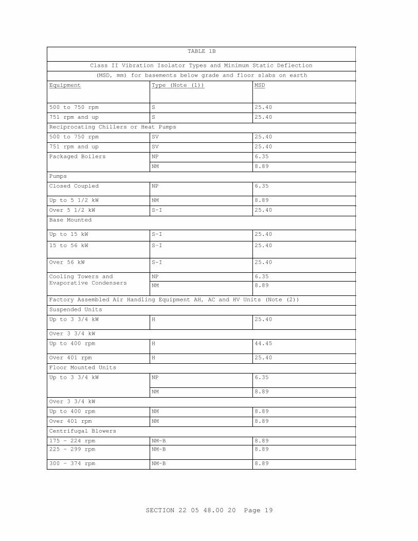
TABLE 1B
Cl ass I I Vi br at i on I sol at or Types and Mi ni mum St at i c Def l ect i on
( MSD, mm) f or basement s bel ow gr ade and f l oor s l abs on ear t h
Equipment Type ( Not e ( 1) ) MSD
500 t o 750 r pm S 25.40
751 r pm and up S 25.40
Reci pr ocat i ng Chi l l er s or Heat Pumps
500 t o 750 r pm SV 25.40
751 r pm and up SV 25.40
Packaged Boi l er s NP 6.35
NM 8.89
Pumps
Cl osed Coupl ed NP 6.35
Up t o 5 1/ 2 kW NM 8.89
Over 5 1/ 2 kW S-I 25.40
Base Mount ed
Up t o 15 kW S-I 25.40
15 t o 56 kW S-I 25.40
Over 56 kW S-I 25.40
Cool i ng Tower s and Evapor at i ve Condenser s
NP 6.35
NM 8.89
Fact or y Assembl ed Ai r Handl i ng Equi pment AH, AC and HV Uni t s ( Not e ( 2) )
Suspended Uni t s
Up t o 3 3/ 4 kW H 25.40
Over 3 3/ 4 kW
Up t o 400 r pm H 44.45
Over 401 r pm H 25.40
Fl oor Mount ed Uni t s
Up t o 3 3/ 4 kW NP 6.35
NM 8.89
Over 3 3/ 4 kW
Up t o 400 r pm NM 8.89
Over 401 r pm NM 8.89
Cent r i f ugal Bl ower s
175 - 224 r pm NM-B 8.89
225 - 299 r pm NM-B 8.89
300 - 374 r pm NM-B 8.89
SECTI ON 22 05 48. 00 20 Page 19

TABLE 1B
Cl ass I I Vi br at i on I sol at or Types and Mi ni mum St at i c Def l ect i on
( MSD, mm) f or basement s bel ow gr ade and f l oor s l abs on ear t h
Equipment Type ( Not e ( 1) ) MSD
375 - 499 r pm NM-B 8.89
Over 500 r pm NM-B 8.89
Tubul ar Cent r i f ugal and Axi al Fans ( Not e ( 2) )
Suspended H wi t h def l ect i ons speci f i ed f or cent r i f ugal bl ower s
Fl oor Mount ed Ar r angement s 1 & 9
NM 8.89
Ut i l i t y Fans ( Not e ( 2) )
Suspended and cent r i f ugal H wi t h def l ect i ons speci f i ed f or
Floor-Mounted NM 8.89
Hi gh Pr essur e Fans ( Over 1494 Pa St at i c Pr essur e) and Ot her Machi ner i es Pr oduci ng Thr ust ( Not e ( 2) )
HR r ecommended f or mi ni mi zi ng undesi r abl e t hr ust ef f ect s
I nt er nal Combust i on Engi nes and Engi ne Dr i ven Equi p
750 r pm and over S 25.40
Di mmer Banks and Tr ansf or mer s
Up t o 454 kg NP 6.35
NM 8.89
Over 454 kg SV 25.40
NOTES: Not e ( 1) and Not e ( 2) ar e same as f or TABLE 1A.
TABLE 1B
Cl ass I I Vi br at i on I sol at or Types and Mi ni mum St at i c Def l ect i on
( MSD, i nches) f or basement s bel ow gr ade and f l oor s l abs on ear t h
Equipment Type ( Not e ( 1) ) MSD
Absor pt i on Ref r i ger at i on Machines
NP 0.25
NM 0.35
Cent r i f ugal Chi l l er s or Heat Pumps
SECTI ON 22 05 48. 00 20 Page 20
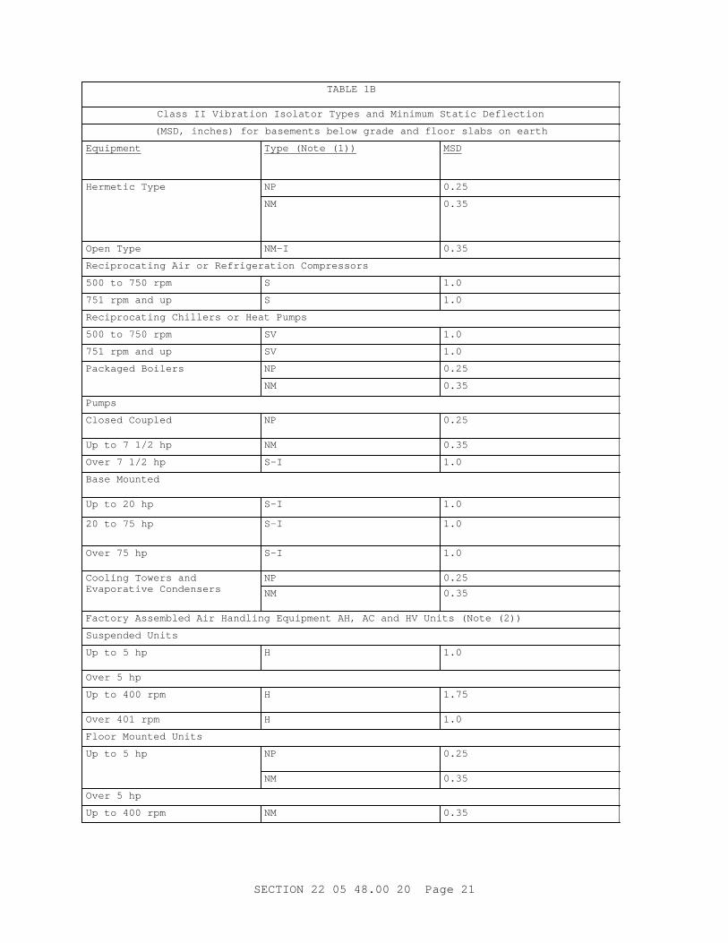
TABLE 1B
Cl ass I I Vi br at i on I sol at or Types and Mi ni mum St at i c Def l ect i on
( MSD, i nches) f or basement s bel ow gr ade and f l oor s l abs on ear t h
Equipment Type ( Not e ( 1) ) MSD
Her met i c Type NP 0.25
NM 0.35
Open Type NM-I 0.35
Reci pr ocat i ng Ai r or Ref r i ger at i on Compr essor s
500 t o 750 r pm S 1.0
751 r pm and up S 1.0
Reci pr ocat i ng Chi l l er s or Heat Pumps
500 t o 750 r pm SV 1.0
751 r pm and up SV 1.0
Packaged Boi l er s NP 0.25
NM 0.35
Pumps
Cl osed Coupl ed NP 0.25
Up t o 7 1/ 2 hp NM 0.35
Over 7 1/ 2 hp S-I 1.0
Base Mount ed
Up t o 20 hp S-I 1.0
20 t o 75 hp S-I 1.0
Over 75 hp S-I 1.0
Cool i ng Tower s and Evapor at i ve Condenser s
NP 0.25
NM 0.35
Fact or y Assembl ed Ai r Handl i ng Equi pment AH, AC and HV Uni t s ( Not e ( 2) )
Suspended Uni t s
Up t o 5 hp H 1.0
Over 5 hp
Up t o 400 r pm H 1.75
Over 401 r pm H 1.0
Fl oor Mount ed Uni t s
Up t o 5 hp NP 0.25
NM 0.35
Over 5 hp
Up t o 400 r pm NM 0.35
SECTI ON 22 05 48. 00 20 Page 21
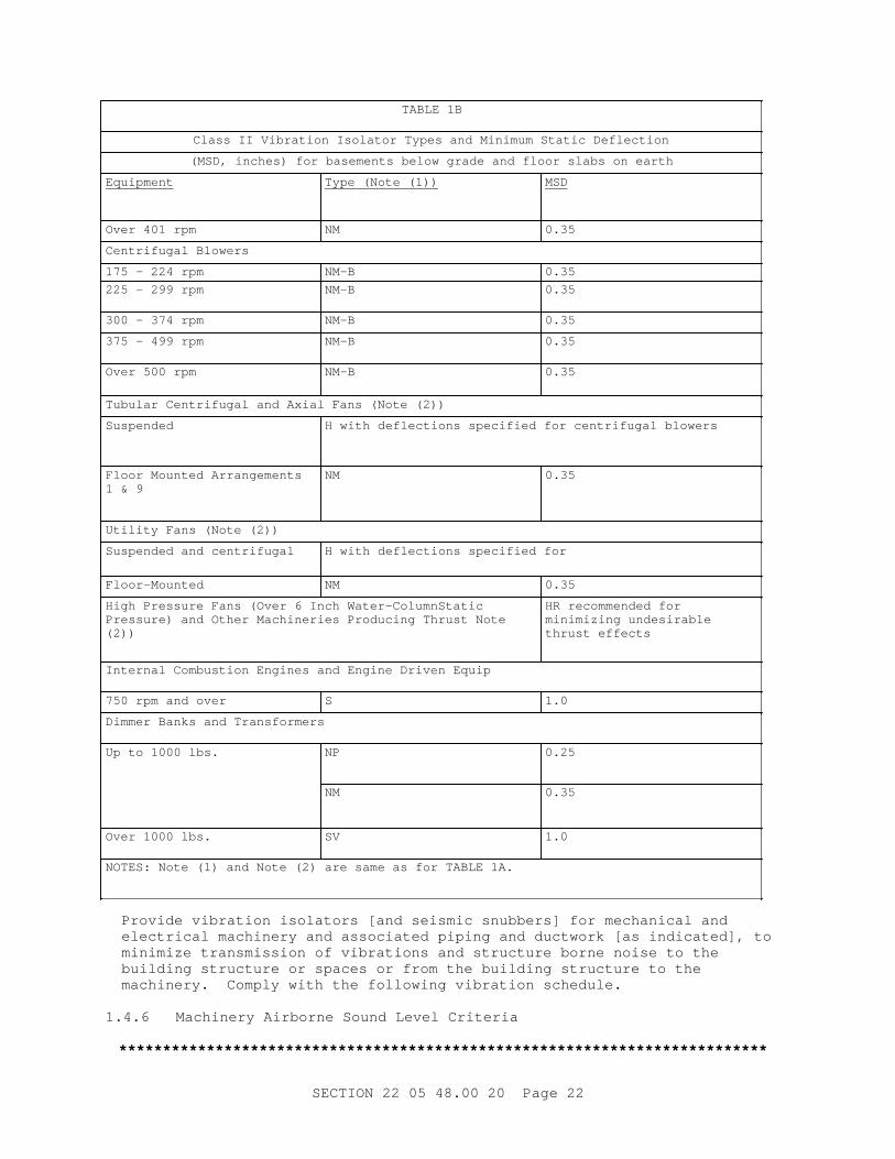
TABLE 1B
Cl ass I I Vi br at i on I sol at or Types and Mi ni mum St at i c Def l ect i on
( MSD, i nches) f or basement s bel ow gr ade and f l oor s l abs on ear t h
Equipment Type ( Not e ( 1) ) MSD
Over 401 r pm NM 0.35
Cent r i f ugal Bl ower s
175 - 224 r pm NM-B 0.35
225 - 299 r pm NM-B 0.35
300 - 374 r pm NM-B 0.35
375 - 499 r pm NM-B 0.35
Over 500 r pm NM-B 0.35
Tubul ar Cent r i f ugal and Axi al Fans ( Not e ( 2) )
Suspended H wi t h def l ect i ons speci f i ed f or cent r i f ugal bl ower s
Fl oor Mount ed Ar r angement s 1 & 9
NM 0.35
Ut i l i t y Fans ( Not e ( 2) )
Suspended and cent r i f ugal H wi t h def l ect i ons speci f i ed f or
Floor-Mounted NM 0.35
Hi gh Pr essur e Fans ( Over 6 I nch Wat er - Col umnSt at i c Pr essur e) and Ot her Machi ner i es Pr oduci ng Thr ust Not e (2))
HR r ecommended f or mi ni mi zi ng undesi r abl e t hr ust ef f ect s
I nt er nal Combust i on Engi nes and Engi ne Dr i ven Equi p
750 r pm and over S 1.0
Di mmer Banks and Tr ansf or mer s
Up t o 1000 l bs. NP 0.25
NM 0.35
Over 1000 l bs. SV 1.0
NOTES: Not e ( 1) and Not e ( 2) ar e same as f or TABLE 1A.
Pr ovi de v i br at i on i sol at or s [ and sei smi c snubber s] f or mechani cal and el ect r i cal machi ner y and associ at ed pi pi ng and duct wor k [ as i ndi cat ed] , t o mi ni mi ze t r ansmi ssi on of v i br at i ons and st r uct ur e bor ne noi se t o t he bui l di ng st r uct ur e or spaces or f r om t he bui l di ng st r uct ur e t o t he machi ner y. Compl y wi t h t he f ol l owi ng v i br at i on schedul e.
1. 4. 6 Machi ner y Ai r bor ne Sound Level Cr i t er i a
**************************************************************************
SECTI ON 22 05 48. 00 20 Page 22
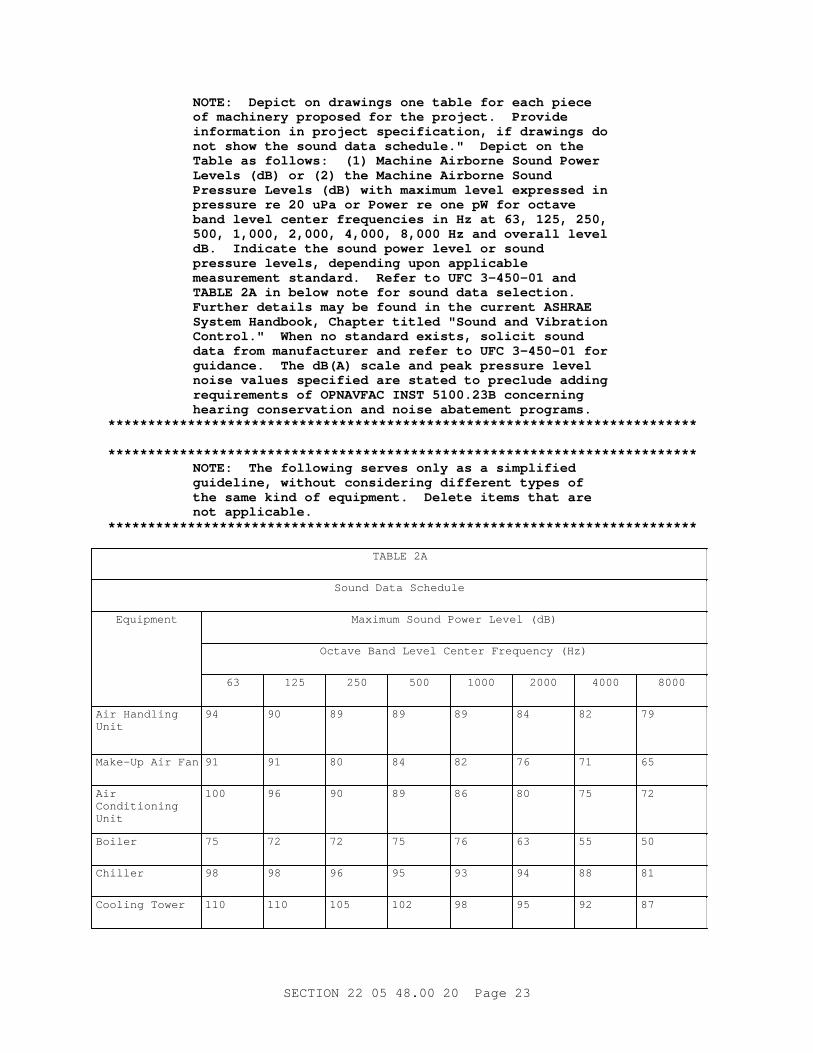
NOTE: Depi ct on dr awi ngs one t abl e f or each pi ece of machi ner y pr oposed f or t he pr oj ect . Pr ovi de i nf or mat i on i n pr oj ect speci f i cat i on, i f dr awi ngs do not show t he sound dat a schedul e. " Depi ct on t he Tabl e as f ol l ows: ( 1) Machi ne Ai r bor ne Sound Power Level s ( dB) or ( 2) t he Machi ne Ai r bor ne Sound Pr essur e Level s ( dB) wi t h maxi mum l evel expr essed i n pr essur e r e 20 uPa or Power r e one pW f or oct ave band l evel cent er f r equenci es i n Hz at 63, 125, 250, 500, 1, 000, 2, 000, 4, 000, 8, 000 Hz and over al l l evel dB. I ndi cat e t he sound power l evel or sound pr essur e l evel s, dependi ng upon appl i cabl e measur ement st andar d. Ref er t o UFC 3- 450- 01 and TABLE 2A i n bel ow not e f or sound dat a sel ect i on. Fur t her det ai l s may be f ound i n t he cur r ent ASHRAE Syst em Handbook, Chapt er t i t l ed " Sound and Vi br at i on Cont r ol . " When no st andar d exi st s, sol i c i t sound dat a f r om manuf act ur er and r ef er t o UFC 3- 450- 01 f or gui dance. The dB( A) scal e and peak pr essur e l evel noi se val ues speci f i ed ar e st at ed t o pr ecl ude addi ng r equi r ement s of OPNAVFAC I NST 5100. 23B concer ni ng hear i ng conser vat i on and noi se abat ement pr ogr ams.
**************************************************************************
**************************************************************************NOTE: The f ol l owi ng ser ves onl y as a s i mpl i f i ed gui del i ne, wi t hout consi der i ng di f f er ent t ypes of t he same ki nd of equi pment . Del et e i t ems t hat ar e not appl i cabl e.
**************************************************************************
TABLE 2A
Sound Dat a Schedul e
Equipment Maxi mum Sound Power Level ( dB)
Oct ave Band Level Cent er Fr equency ( Hz)
63 125 250 500 1000 2000 4000 8000
Ai r Handl i ng Unit
94 90 89 89 89 84 82 79
Make- Up Ai r Fan 91 91 80 84 82 76 71 65
Air Conditioning Unit
100 96 90 89 86 80 75 72
Boiler 75 72 72 75 76 63 55 50
Chiller 98 98 96 95 93 94 88 81
Cool i ng Tower 110 110 105 102 98 95 92 87
SECTI ON 22 05 48. 00 20 Page 23

TABLE 2A
Sound Dat a Schedul e
Equipment Maxi mum Sound Power Level ( dB)
Oct ave Band Level Cent er Fr equency ( Hz)
63 125 250 500 1000 2000 4000 8000
Ai r Compr essor 90 89 92 93 92 92 90 81
Pump 85 80 82 82 80 77 74 72
Fan 55 50 48 47 48 46 42 37
1. 4. 6. 1 Basi c Cr i t er i a
For each pi ece of machi ner y i n t he human wor k envi r onment , do not exceed t he maxi mum ai r bor ne sound l evel s 84 dB A- wei ght ed scal e, cont i nuous or i nt er mi t t ent , or 140 dB peak sound pr essur e- l evel , i mpact or i mpul se, noi se.
1. 4. 6. 2 Sound Dat a Schedul e
**************************************************************************NOTE: Depi ct on dr awi ngs one t abl e f or each pi ece of machi ner y pr oposed f or t he pr oj ect . Pr ovi de i nf or mat i on i n pr oj ect speci f i cat i on, i f dr awi ngs do not show t he sound dat a schedul e. " Depi ct on t he Tabl e as f ol l ows: ( 1) Machi ne Ai r bor ne Sound Power Level s ( dB) or ( 2) t he Machi ne Ai r bor ne Sound Pr essur e Level s ( dB) wi t h maxi mum l evel expr essed i n pr essur e r e 20 uPa or Power r e one pW f or oct ave band l evel cent er f r equenci es i n Hz at 63, 125, 250, 500, 1, 000, 2, 000, 4, 000, 8, 000 Hz and over al l l evel dB. I ndi cat e t he sound power l evel or sound pr essur e l evel s, dependi ng upon appl i cabl e measur ement st andar d. Ref er t o UFC 3- 450- 01 and TABLE 2A i n bel ow not e f or sound dat a sel ect i on. Fur t her det ai l s may be f ound i n t he cur r ent ASHRAE Syst em Handbook, Chapt er t i t l ed " Sound and Vi br at i on Cont r ol . " When no st andar d exi st s, sol i c i t sound dat a f r om manuf act ur er and r ef er t o UFC 3- 450- 01 f or gui dance. The dB( A) scal e and peak pr essur e l evel noi se val ues speci f i ed ar e st at ed t o pr ecl ude addi ng r equi r ement s of OPNAVFAC I NST 5100. 23B concer ni ng hear i ng conser vat i on and noi se abat ement pr ogr ams.
**************************************************************************
**************************************************************************NOTE: The f ol l owi ng ser ves onl y as a s i mpl i f i ed gui del i ne, wi t hout consi der i ng di f f er ent t ypes of t he same ki nd of equi pment . Del et e i t ems t hat ar e not appl i cabl e.
**************************************************************************
SECTI ON 22 05 48. 00 20 Page 24

TABLE 2A
Sound Dat a Schedul e
Equipment Maxi mum Sound Power Level ( dB)
Oct ave Band Level Cent er Fr equency ( Hz)
63 125 250 500 1000 2000 4000 8000
Ai r Handl i ng Unit
94 90 89 89 89 84 82 79
Make- Up Ai r Fan 91 91 80 84 82 76 71 65
Air Conditioning Unit
100 96 90 89 86 80 75 72
Boiler 75 72 72 75 76 63 55 50
Chiller 98 98 96 95 93 94 88 81
Cool i ng Tower 110 110 105 102 98 95 92 87
Ai r Compr essor 90 89 92 93 92 92 90 81
Pump 85 80 82 82 80 77 74 72
Fan 55 50 48 47 48 46 42 37
1. 4. 7 Sei smi c Pr ot ect i on Cr i t er i a
**************************************************************************NOTE: Pr ot ect el ect r i cal and mechani cal machi ner y i nst al l at i ons i n Sei smi c Zones 3 and 4 of t he Uni f or m Bui l di ng Code Sei smi c Map. Hor i zont al f or ce f act or s of 1. 00 ar e assi gned t o essent i al bui l di ng or st r uct ur es. 0. 60 f act or s ar e assi gned t o non- essent i al bui l di ngs or st r uct ur es. A non- essent i al bui l di ng or st r uct ur e i s one t hat does not r equi r e compl et e oper at i on of emer gency or l i f e savi ng machi ner y t o pr ovi de ser vi ces af t er an ear t hquake. An essent i al bui l di ng or st r uct ur e r equi r es t hese ser vi ces of i t s r est r ai ned machi ner y.
**************************************************************************
Use a Hor i zont al For ce Fact or mi ni mum [ 60 per cent ] [ 100 per cent ] of t he machi ner y wei ght consi der ed passi ng t hr ough t he machi ner y cent er of gr avi t y i n any hor i zont al di r ect i on. Unl ess v i br at i on i sol at i on i s r equi r ed t o pr ot ect machi ner y agai nst unaccept abl e st r uct ur e t r ansmi t t ed noi se or v i br at i on, pr ot ect t he st r uct ur e or machi ner y f r om ear t hquakes by r i gi d st r uct ur al l y sound at t achment t o t he l oad- suppor t i ng st r uct ur e. Pr ot ect each pi ece of v i br at i on- i sol at ed machi ner y wi t h pr ot ect ed spr i ng i sol at or s or separ at e sei smi c r est r ai nt devi ces. Det er mi ne by cal cul at i ons t he number and si ze of sei smi c r est r ai nt s needed f or each machi ner y. Ver i f y sei smi c r est r ai nt vendor ' s cal cul at i ons by a r egi st er ed pr of essi onal
SECTI ON 22 05 48. 00 20 Page 25

engi neer . Pr ovi de sei smi c snubber s and pr ot ect ed spr i ng i sol at or s r at ed i n t hr ee pr i nci pl e axes. Ver i f y r at i ngs by i ndependent l abor at or y t est i ng, [ by anal ysi s of an i ndependent l i censed st r uct ur al engi neer ] [ , or ] [ by R- number r at i ngs by Cal i f or ni a St at e] .
1. 4. 8 Welding
AWS D1. 1/ D1. 1M.
1. 5 SUBMITTALS
**************************************************************************NOTE: Submi t t al s must be l i mi t ed t o t hose necessar y f or adequat e qual i t y cont r ol . The i mpor t ance of an i t em i n t he pr oj ect shoul d be one of t he pr i mar y f act or s i n det er mi ni ng i f a submi t t al f or t he i t em shoul d be r equi r ed.
A " G" f ol l owi ng a submi t t al i t em i ndi cat es t hat t he submi t t al r equi r es Gover nment appr oval . Some submi t t al s ar e al r eady mar ked wi t h a " G" . Onl y del et e an exi st i ng " G" i f t he submi t t al i t em i s not compl ex and can be r evi ewed t hr ough t he Cont r act or ’ s QC syst em. Onl y add a " G" i f t he submi t t al i s suf f i c i ent l y i mpor t ant or compl ex i n cont ext of t he project.
For submi t t al s r equi r i ng Gover nment appr oval on Ar my pr oj ect s, a code of up t o t hr ee char act er s wi t hi n t he submi t t al t ags may be used f ol l owi ng t he " G" desi gnat i on t o i ndi cat e t he appr ovi ng aut hor i t y. Codes f or Ar my pr oj ect s usi ng t he Resi dent Management Syst em ( RMS) ar e: " AE" f or Ar chi t ect - Engi neer ; " DO" f or Di st r i c t Of f i ce ( Engi neer i ng Di v i s i on or ot her or gani zat i on i n t he Di st r i c t Of f i ce) ; " AO" f or Ar ea Of f i ce; " RO" f or Resi dent Of f i ce; and " PO" f or Pr oj ect Of f i ce. Codes f ol l owi ng t he " G" t ypi cal l y ar e not used f or Navy, Ai r For ce and NASA pr oj ect s.
Use t he " S" c l assi f i cat i on onl y i n SD- 11 Cl oseout Submi t t al s. The " S" f ol l owi ng a submi t t al i t em i ndi cat es t hat t he submi t t al i s r equi r ed f or t he Sust ai nabi l i t y eNot ebook t o f ul f i l l f eder al l y mandat ed sust ai nabl e r equi r ement s i n accor dance wi t h 01 33 29 SUSTAI NABI LI TY REPORTI NG.
Choose t he f i r st br acket ed i t em f or Navy, Ai r For ce and NASA pr oj ect s, or choose t he second br acket ed i t em f or Ar my pr oj ect s.
**************************************************************************
Gover nment appr oval i s r equi r ed f or submi t t al s wi t h a " G" desi gnat i on; submi t t al s not havi ng a " G" desi gnat i on ar e [ f or Cont r act or QC appr oval . ] [ f or i nf or mat i on onl y. When used, a desi gnat i on f ol l owi ng t he " G" desi gnat i on i dent i f i es t he of f i ce t hat wi l l r evi ew t he submi t t al f or t he Gover nment . ] Submi t t al s wi t h an " S" ar e f or i ncl usi on i n t he Sust ai nabi l i t y eNot ebook, i n conf or mance t o Sect i on 01 33 29, SUSTAI NABI TY REPORTI NG. Submi t t he f ol l owi ng i n accor dance wi t h Sect i on 01 33 00
SECTI ON 22 05 48. 00 20 Page 26

SUBMI TTAL PROCEDURES:
SD- 02 Shop Dr awi ngs
[ I ner t i a Bases]
[ Machi ner y Bases]
[ Platforms ]
[ Rails ]
[ Saddles ]
SD- 03 Pr oduct Dat a
Isolators
Fl exi bl e Connect or s
Fl exi bl e Duct Connect or s
Pi pe Gui des
[ Sei smi c Snubber s]
[ Ver t i cal St ops]
[ Thr ust Rest r ai nt s]
[ I ner t i a Bases]
[ Machi ner y Bases]
[ Machi ner y Foundat i ons and Subbases]
[ Platforms ]
[ Rails ]
[ Saddles ]
Machi ner y Manuf act ur er ' s Sound Dat a
SD- 05 Desi gn Dat a
**************************************************************************NOTE: When maxi mum and mi ni mum l i mi t s of equi pment s i ze, wei ght , et c. , ar e cr i t i cal t o t he bui l di ngs' st r uct ur al desi gn, t hese l i mi t s shal l be i ndi cat ed or speci f i ed.
**************************************************************************
[ I ner t i a Bases]
[ Machi ner y Bases]
[ Platforms ]
SECTI ON 22 05 48. 00 20 Page 27

[ Rails ]
[ Saddles ]
Each I t em of Machi ner y
Each I t em of Machi ner y over 136 Ki l ogr ams Machi ner y Over 300 Pounds
Submi t desi gn cal cul at i ons f or [ i ner t i a bases] , [ machi ner y bases] , [ pl at f or ms] , [ r ai l s ] , and [ saddl es] , ei t her by t he machi ner y manuf act ur er f or t he r ecommended machi ner y mount i ng or by t he v i br at i on- i sol at i on equi pment manuf act ur er .
SD- 06 Test Repor t s
[ Sei smi c Snubber s]
Equi pment Vi br at i on Test s
Equi pment Sound Level Test s
[ Pr ot ect ed Spr i ng I sol at or s]
[ Submi t sei smi c pr ot ect i on r at i ng i n t hr ee pr i nci pal axes cer t i f i ed by an i ndependent l abor at or y or anal yzed by an i ndependent l i censed st r uct ur al engi neer . ]
SD- 08 Manuf act ur er ' s I nst r uct i ons
Vi br at i on and Noi se I sol at i on Component s
[ Sei smi c Pr ot ect i on Component s]
1. 6 QUALI TY ASSURANCE
1. 6. 1 Vi br at i on I sol at or Pr ocur ement
For each pi ece of machi ner y t o be i sol at ed f r om vi br at i on, suppl y t he [ i ner t i a base] , [ machi ner y base] , [ pl at f or m] , [ r ai l s ] , [ saddl es] , [ v i br at i on i sol at or s] , [ sei smi c snubber s] , and ot her associ at ed mat er i al s and equi pment as a coor di nat ed package by a s i ngl e manuf act ur er or by t he machi ner y manuf act ur er . Sel ect i sol at or s t hat pr ovi de uni f or m def l ect i on even when machi ner y wei ght i s not evenl y di st r i but ed. Thi s r equi r ement does not i ncl ude t he f l exi bl e connect or s or t he hanger s f or t he associ at ed pi pi ng and duct wor k.
1. 6. 2 Uni t i zed Machi ner y Assembl i es
Mount i ng of uni t i zed assembl i es di r ect l y on v i br at i on i sol at i on spr i ngs i s accept abl e i f machi ner y manuf act ur er cer t i f i es t hat t he end suppor t s of t he assembl i es have been desi gned f or such i nst al l at i on.
PART 2 PRODUCTS
**************************************************************************NOTE: I ncl ude t he v i br at i on i sol at i on schedul e on t he dr awi ngs. Pr ovi de i nf or mat i on i n pr oj ect speci f i cat i ons, i f dr awi ngs do not show t he v i br at i on i sol at i on schedul e. Fur t her det ai l s may
SECTI ON 22 05 48. 00 20 Page 28

be f ound i n t he cur r ent ASHRAE Syst em Handbook, Chapt er t i t l ed " Sound and Vi br at i on Cont r ol . " Ref er t o TABLES 1A and 1B f or v i br at i on i sol at or sel ect i on. DO NOT I NCLUDE THE ENTI RE TABLES 1A AND 1B I N THE PROJECT SPECI FI CATI ONS.
**************************************************************************
**************************************************************************NOTE: Depi ct on dr awi ngs one t abl e f or each pi ece of machi ner y pr oposed f or t he pr oj ect . Pr ovi de i nf or mat i on i n pr oj ect speci f i cat i on, i f dr awi ngs do not show t he sound dat a schedul e. " Depi ct on t he Tabl e as f ol l ows: ( 1) Machi ne Ai r bor ne Sound Power Level s ( dB) or ( 2) t he Machi ne Ai r bor ne Sound Pr essur e Level s ( dB) wi t h maxi mum l evel expr essed i n pr essur e r e 20 uPa or Power r e one pW f or oct ave band l evel cent er f r equenci es i n Hz at 63, 125, 250, 500, 1, 000, 2, 000, 4, 000, 8, 000 Hz and over al l l evel dB. I ndi cat e t he sound power l evel or sound pr essur e l evel s, dependi ng upon appl i cabl e measur ement st andar d. Ref er t o UFC 3- 450- 01 and TABLE 2A i n second not e i n par agr aph MACHI NERY AI RBORNE SOUND LEVEL CRI TERI A f or sound dat a sel ect i on. Fur t her det ai l s may be f ound i n t he cur r ent ASHRAE Syst em Handbook, Chapt er t i t l ed " Sound and Vi br at i on Cont r ol . " When no st andar d exi st s, sol i c i t sound dat a f r om manuf act ur er and r ef er t o UFC 3- 450- 01 f or gui dance. The dB( A) scal e and peak pr essur e l evel noi se val ues speci f i ed ar e st at ed t o pr ecl ude addi ng r equi r ement s of OPNAVFAC I NST 5100. 23B concer ni ng hear i ng conser vat i on and noi se abat ement pr ogr ams.
**************************************************************************
2. 1 CORROSI ON PROTECTI ON FOR STEEL PARTS
[ ASTM A123/ A123M] [ ASTM A653/ A653M] hot - di pped gal vani zed, or equi val ent manuf act ur er st andar d coat i ngs. Wher e st eel par t s ar e exposed t o t he weat her , pr ovi de gal vani zed coat i ng of at l east 0. 61 kg 2 ounces of z i nc per squar e met er f oot of sur f ace. Coat spr i ngs wi t h neopr ene.
2. 2 NEOPRENE
ASTM D471 and ASTM D2240, Gr ade Dur omet er 40, 50, or 60, and oi l r esi st ant .
2. 3 FLOOR- MOUNTED I SOLATORS
2. 3. 1 Neopr ene I sol at i on Pads
Pr ovi de pads at l east 6 mm 1/ 4 i nch t hi ck wi t h cr oss- r i bbed or waf f l e desi gn. For concent r at ed l oads, pr ovi de st eel bear i ng pl at es bonded or col d cement ed t o t he pads.
2. 3. 2 Neopr ene I sol at or s
Pr ovi de mol ded neopr ene i sol at or s havi ng st eel base pl at es wi t h mount i ng hol es and, at t he t op, st eel mount i ng pl at es wi t h mount i ng hol es or t hr eaded i nser t s. Pr ovi de el ement s of t ype and si ze coded wi t h mol ded l et t er s or col or - coded f or capaci t y i dent i f i cat i on. Embed met al par t s
SECTI ON 22 05 48. 00 20 Page 29

compl et el y i n neopr ene.
2. 4 SPRI NG I SOLATORS AND PROTECTED SPRI NG I SOLATORS
Pr ovi de spr i ng i sol at or s or pr ot ect ed spr i ng i sol at or s t hat ar e adj ust abl e and l at er al l y st abl e wi t h f r ee- st andi ng spr i ngs of hor i zont al st i f f ness at mi ni mum 80 per cent of t he ver t i cal ( axi al ) st i f f ness. For machi ne- at t ached and f l oor - at t ached r est r ai ni ng el ement s, separ at e f r om met al - t o- met al cont act by neopr ene cushi ons 3 mm 1/ 8 i nch t hi ck mi ni mum. Pr ovi de neopr ene acoust i c f r i c t i on pads at l east 6 mm 1/ 4 i nch t hi ck.
2. 4. 1 Springs
Pr ovi de spr i ngs wi t h base and compr essi on pl at es, t o keep spr i ng ends par al l el dur i ng and af t er def l ect i on t o oper at i ng hei ght . Pr ovi de out s i de coi l di amet er s at l east 0. 8 of t he oper at i ng hei ght . At oper at i ng hei ght , spr i ngs shal l have addi t i onal t r avel t o compl et e ( sol i d) compr essi on equal t o at l east 50 per cent of t he oper at i ng def l ect i on.
2. 4. 2 Mount i ng and Adj ust ment
Pr ovi de base and compr essi on pl at es wi t h mount i ng hol es or t hr eaded f i t t i ngs. Bol t l evel i ng adj ust ment bol t s t o machi ner y or base.
2. 5 SUSPENSI ON I SOLATORS
Pr ovi de hanger s wi t h suspensi on i sol at or s encased i n open st eel br acket s. I sol at e hanger r ods f r om i sol at or st eel br acket s wi t h neopr ene- l i ned opening.
2. 5. 1 Suspensi on Neopr ene I sol at or s
Pr ovi de doubl e- def l ect i on el ement s wi t h mi ni mum 10 mm 3/ 8 i nch def l ect i on.
2. 5. 2 Suspensi on Spr i ng I sol at or s
Pr ovi de hanger s wi t h spr i ngs and mol ded neopr ene el ement s i n ser i es. Pr ovi de i sol at or s wi t h adj ust abl e spr i ng- pr el oadi ng devi ces wher e r equi r ed t o mai nt ai n const ant pi pe el evat i ons dur i ng i nst al l at i on and when pi pe oper at i onal l oads ar e t r ansf er r ed t o t he spr i ngs.
2. 6 [ MACHI NERY BASES] [ , PLATFORMS] [ , RAI LS] [ SADDLES]
ASTM A36/ A36M and AI SC 360.
2. 7 I NERTI A BASES
ASTM A36/ A36M st eel , ASTM C94/ C94M ( [ 20 MPa] [ 2, 500 psi ] [ _____] ) concr et e.
2. 8 FLEXI BLE CONNECTORS FOR PI PI NG
St r ai ght or el bow f l exi bl e connect or s r at ed f or t emper at ur es, pr essur es, and f l ui ds t o be conveyed. Pr ovi de f l exi bl e connect or s wi t h t he st r engt h 4 t i mes oper at i ng pr essur e at hi ghest syst em oper at i ng t emper at ur e. Pr ovi de el bow f l exi bl e connect or s wi t h a per manent l y set angl e.
2. 8. 1 El ast omer i c Fl exi bl e Connect or s
Fabr i cat ed of mul t i pl e pl i es of t i r e cor d f abr i c and el ast omer i c mat er i al s
SECTI ON 22 05 48. 00 20 Page 30
wi t h i nt egr al r ei nf or ced el ast omer i c f l anges wi t h gal vani zed mal l eabl e i r on back up r i ngs.
2. 8. 2 Met al Fl exi bl e Connect or s
Fabr i cat ed of Gr ade E phosphor br onze, monel or cor r ugat ed st ai nl ess st eel t ube cover ed wi t h compar abl e br onze or st ai nl ess st eel br ai d r est r ai ni ng and pr essur e cover .
2. 9 FLEXI BLE DUCT CONNECTORS
Pr ovi de f l exi bl e duct connect or s f abr i cat ed i n accor dance wi t h [ SMACNA 1403] [ SMACNA 1966].
[ 2. 10 SEI SMI C SNUBBERS FOR EQUI PMENT
Fact or y- f abr i cat ed, omni - di r ect i onal wi t h f act or y set ai r gaps bet ween 3 mm 1/ 8 i nch mi ni mum and 6 mm 1/ 4 i nch maxi mum. Load capaci t y of each snubber at 50 per cent neopr ene el ement def l ect i on shal l be [ 0. 5g] [ 1. 0g] mi ni mum. Pr ovi de r epl aceabl e neopr ene el ement s [ 6 mm] [ 19 mm] [ 1/ 4 i nch] [ 3/ 4 i nch] [ _____] mi ni mum t hi ckness.
] 2. 11 PI PE GUI DES
Fact or y- f abr i cat ed. Wel d st eel bar gui des t o t he pi pe at a maxi mum r adi al spaci ng of 60 degr ees. The out s i de di amet er ar ound t he gui de bar s shal l be smal l er t han t he i nsi de di amet er of t he gui de s l eeve i n accor dance wi t h st andar d f i el d const r uct i on pr act i ce. For pi pe t emper at ur es bel ow 16 degr ees C 60 degr ees F, pr ovi de met al s l eeve, mi ni mum 16 kg per cubi c met er one pound per cubi c f oot densi t y i nsul at i on.
2. 12 THRUST RESTRAI NTS
Adj ust abl e spr i ng t hr ust r est r ai nt s, abl e t o r esi st t he t hr ust f or ce wi t h at l east 25 per cent unused capaci t y. The oper at i ng spr i ng def l ect i on shal l be not l ess t han 50 per cent of t he st at i c def l ect i on of t he i sol at i on suppor t i ng t he machi ner y.
2. 13 [ SEI SMI C PROTECTI ON COMPONENTS FOR [ PI PI NG] [ AND] [ DUCTWORK]
[ Sect i on 23 03 00. 00 20 BASI C MECHANI CAL MATERI ALS AND METHODS. ] [ SMACNA 1981.]]
PART 3 EXECUTI ON
3. 1 INSTALLATION
3. 1. 1 Vi br at i on and Noi se I sol at i on Component s
**************************************************************************NOTE: I ncl ude t he v i br at i on i sol at i on schedul e on t he dr awi ngs. Pr ovi de i nf or mat i on i n pr oj ect speci f i cat i ons, i f dr awi ngs do not show t he v i br at i on i sol at i on schedul e. Fur t her det ai l s may be f ound i n t he cur r ent ASHRAE Syst em Handbook, Chapt er t i t l ed " Sound and Vi br at i on Cont r ol . " Ref er t o TABLES 3A and 3B f or v i br at i on i sol at or sel ect i on. DO NOT I NCLUDE THE ENTI RE TABLES 3A AND 3B I N THE PROJECT SPECI FI CATI ONS.
SECTI ON 22 05 48. 00 20 Page 31

**************************************************************************
I nst al l v i br at i on- and- noi se i sol at i on mat er i al s and equi pment [ as i ndi cat ed and] i n accor dance wi t h machi ner y manuf act ur er ' s i nst r uct i ons.
3. 1. 2 Suspensi on Vi br at i on I sol at or s
Pr ovi de suspensi on i sol at i on hanger s f or pi pi ng, suspended equi pment , and suspended equi pment pl at f or ms i n mechani cal equi pment r ooms, [ as i ndi cat ed and] as speci f i ed. For oper at i ng l oad st at i c def l ect i ons of 6 mm 1/ 4 i nch or l ess, pr ovi de neopr ene pads or s i ngl e def l ect i on neopr ene i sol at or s. For oper at i ng l oad st at i c def l ect i ons over 8 t o 10 mm 5/ 16 t o 3/ 8 i nch, pr ovi de doubl e- def l ect i on neopr ene el ement i sol at or s. For oper at i ng l oad st at i c def l ect i ons over 10 mm 3/ 8 i nch, pr ovi de i sol at or s wi t h spr i ng and neopr ene el ement s i n ser i es.
3. 1. 3 Ver t i cal St ops
For machi ner y af f ect ed by wi nd pr essur e or havi ng an oper at i onal wei ght di f f er ent f r om i nst al l ed wei ght , pr ovi de r esi l i ent ver t i cal l i mi t s t ops whi ch pr event spr i ng ext ensi on when wei ght i s r emoved. Pr ovi de ver t i cal st ops f or machi ner y cont ai ni ng l i qui d, such as wat er chi l l er s, evapor at i ve cool er s, boi l er s, and cool i ng t ower s. Spr i ng i sol at ed or pr ot ect ed spr i ng i sol at ed machi ner y must r ock and move f r eel y wi t hi n l i mi t s of st ops or sei smi c r est r ai nt devi ces.
3. 1. 4 Thr ust Rest r ai nt s
Wher e r equi r ed, pr ovi de pai r s of t hr ust r est r ai nt s, symmet r i cal l y i nst al l ed on bot h s i des of t he st eady st at e l i ne of t hr ust .
3. 1. 5 Fl exi bl e Pi pe and Duct Connect or s
I nst al l f l exi bl e connect or s i n accor dance wi t h t he manuf act ur er ' s i nst r uct i ons. When l i qui d pul sat i on dampeni ng i s r equi r ed, f l exi bl e connect or s wi t h spher i cal conf i gur at i on may be used. [ Pr ovi de r est r ai nt s f or pi pe connect or s at pumps t o pr event connect or f ai l ur e upon pump startup.]
[ 3. 1. 6 Sei smi c Snubber s
Pr ovi de snubber s as c l ose as possi bl e t o each vi br at i on i sol at or as i ndi cat ed. Af t er i nst al l i ng and l evel i ng of t he machi ner y, adj ust snubber s i n accor dance wi t h t he snubber manuf act ur er ' s i nst r uct i ons.
] 3. 1. 7 Machinery
**************************************************************************NOTE: When maxi mum and mi ni mum l i mi t s of equi pment s i ze, wei ght , et c. , ar e cr i t i cal t o t he bui l di ngs' st r uct ur al desi gn, t hese l i mi t s shal l be i ndi cat ed or speci f i ed.
**************************************************************************
Pr ovi de v i br at i on i sol at or s, f l ex i bl e connect or s [ and sei smi c snubber s] i n accor dance wi t h manuf act ur er ' s r ecommendat i ons. Machi ner y wi t h spr i ng i sol at or s or pr ot ect ed spr i ng i sol at or s shal l r ock or move f r eel y wi t hi n l i mi t s of st ops or sei smi c snubber r est r ai nt s.
SECTI ON 22 05 48. 00 20 Page 32
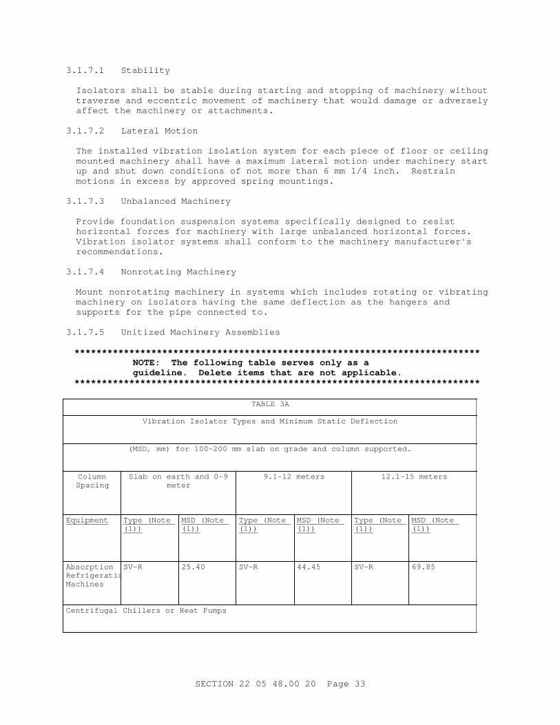
3. 1. 7. 1 Stability
I sol at or s shal l be st abl e dur i ng st ar t i ng and st oppi ng of machi ner y wi t hout t r aver se and eccent r i c movement of machi ner y t hat woul d damage or adver sel y af f ect t he machi ner y or at t achment s.
3. 1. 7. 2 Lat er al Mot i on
The i nst al l ed v i br at i on i sol at i on syst em f or each pi ece of f l oor or cei l i ng mount ed machi ner y shal l have a maxi mum l at er al mot i on under machi ner y st ar t up and shut down condi t i ons of not mor e t han 6 mm 1/ 4 i nch. Rest r ai n mot i ons i n excess by appr oved spr i ng mount i ngs.
3. 1. 7. 3 Unbal anced Machi ner y
Pr ovi de f oundat i on suspensi on syst ems speci f i cal l y desi gned t o r esi st hor i zont al f or ces f or machi ner y wi t h l ar ge unbal anced hor i zont al f or ces. Vi br at i on i sol at or syst ems shal l conf or m t o t he machi ner y manuf act ur er ' s recommendations.
3. 1. 7. 4 Nonr ot at i ng Machi ner y
Mount nonr ot at i ng machi ner y i n syst ems whi ch i ncl udes r ot at i ng or v i br at i ng machi ner y on i sol at or s havi ng t he same def l ect i on as t he hanger s and suppor t s f or t he pi pe connect ed t o.
3. 1. 7. 5 Uni t i zed Machi ner y Assembl i es
**************************************************************************NOTE: The f ol l owi ng t abl e ser ves onl y as a gui del i ne. Del et e i t ems t hat ar e not appl i cabl e.
**************************************************************************
TABLE 3A
Vi br at i on I sol at or Types and Mi ni mum St at i c Def l ect i on
( MSD, mm) f or 100- 200 mm sl ab on gr ade and col umn suppor t ed.
ColumnSpacing
Sl ab on ear t h and 0- 9meter
9. 1- 12 met er s 12. 1- 15 met er s
Equipment Type ( Not e (1))
MSD ( Not e (1))
Type ( Not e (1))
MSD ( Not e (1))
Type ( Not e (1))
MSD ( Not e (1))
Absorption Refrigeration Machines
SV-R 25.40 SV-R 44.45 SV-R 69.85
Cent r i f ugal Chi l l er s or Heat Pumps
SECTI ON 22 05 48. 00 20 Page 33

TABLE 3A
Vi br at i on I sol at or Types and Mi ni mum St at i c Def l ect i on
( MSD, mm) f or 100- 200 mm sl ab on gr ade and col umn suppor t ed.
ColumnSpacing
Sl ab on ear t h and 0- 9meter
9. 1- 12 met er s 12. 1- 15 met er s
Equipment Type ( Not e (1))
MSD ( Not e (1))
Type ( Not e (1))
MSD ( Not e (1))
Type ( Not e (1))
MSD ( Not e (1))
Hermetic Type
SV-B 44.45 SV-B 63.50 SV-B 88.90
Open Type SV-1 44.45 SV-I 63.50 SV-I 88.90
Reci pr ocat i ng Ai r or Ref r i ger at i on Compr essor s
500 t o 750 rpm
S-R 44.45 S-R 63.50 S-R 88.90
751 r pm and up
S-R 38.10 S-R 63.50 S-R 88.90
Reci pr ocat i ng Chi l l er s or Heat Pumps
500 t o 750 rpm
SV-R 44.45 SV-R 63.50 SV-R 88.90
751 r pm and up
SV-R 38.10 SV-R 63.50 SV-R 88.90
Packaged Boilers
SV 25.40 SV 63.50 SV-R 88.90
Cl osed Coupl ed Pumps
Up t o 5 1/ 2 kW
S-I 25.40 S-I 25.40 S-I 25.40
Over 5 1/ 2 kW
S-I 38.10 S-I 63.50 S-I 63.50
Base Mount ed Pumps
Up t o 15 kW S-I 38.10 S-I 63.50 S-I 63.50
15 t o 56 kW S-I 38.10 S-I 63.50 S-I 88.90
SECTI ON 22 05 48. 00 20 Page 34

TABLE 3A
Vi br at i on I sol at or Types and Mi ni mum St at i c Def l ect i on
( MSD, mm) f or 100- 200 mm sl ab on gr ade and col umn suppor t ed.
ColumnSpacing
Sl ab on ear t h and 0- 9meter
9. 1- 12 met er s 12. 1- 15 met er s
Equipment Type ( Not e (1))
MSD ( Not e (1))
Type ( Not e (1))
MSD ( Not e (1))
Type ( Not e (1))
MSD ( Not e (1))
Over 56 kW S-I 63.50 S-I 88.90 S-I 88.90
Cool i ng Tower s and Evapor at i ve Condenser s
SV wi t h def l ect i ons speci f i ed f or cent r i f ugal bl ower s when spr i ngs ar e suppor t ed on beams. Use def l ect i on l i s t ed f or col umn suppor t ed f l oor s wi t h up t o 9 met er s col umn spaci ng when spr i ngs ar e l ocat ed on col umns or bear i ng wal l s.
Fact or y Assembl ed Ai r Handl i ng Equi pment AH, AC and HV Uni t s ( Not e ( 2) )
Suspended Uni t s
Up t o 3 3/ 4 kW
H 25.40 H 25.40 H 25.40
Over 3 3/ 4 kW
Up t o 400 rpm
H 44.45 H 44.45 H 44.45
Over 401 rpm
H 25.40 H 38.10 H 63.50
Fl oor Mount ed Uni t s
Up t o 3 3/ 4 kW
S 25.40 S 25.40 S 25.40
Over 3 3/ 4 kW
Up t o 400 rpm
S-R 44.45 S-R 44.45 S-R 63.50
Over 401 rpm
S-R 25.40 S-R 38.10 S-R 63.50
Cent r i f ugal Bl ower s
175 - 224 rpm
S-B 120.65 S-B 120.65 S-B 120.65
225 - 299 rpm
S-B 95.25 S-B 120.65 S-B 120.65
SECTI ON 22 05 48. 00 20 Page 35

TABLE 3A
Vi br at i on I sol at or Types and Mi ni mum St at i c Def l ect i on
( MSD, mm) f or 100- 200 mm sl ab on gr ade and col umn suppor t ed.
ColumnSpacing
Sl ab on ear t h and 0- 9meter
9. 1- 12 met er s 12. 1- 15 met er s
Equipment Type ( Not e (1))
MSD ( Not e (1))
Type ( Not e (1))
MSD ( Not e (1))
Type ( Not e (1))
MSD ( Not e (1))
300 - 374 rpm
S-B 69.85 S-B 114.30 S-B 120.65
375 - 499 rpm
S-B 63.50 S-B 88.90 S-B 114.30
Over 500 rpm
S-B 44.45 S-B 63.50 S-B 88.90
Tubul ar Cent r i f ugal and Axi al Fans ( Not e ( 2) )
Suspended H wi t h def l ect i on speci f i ed f or cent r i f ugal bl ower s
Fl oor Mount ed Ar r angement s 1 & 9
S- B wi t h def l ect i ons speci f i ed f or cent r i f ugal bl ower s
Ut i l i t y Fans ( Not e ( 2) )
Suspended H wi t h def l ect i ons speci f i ed f or cent r i f ugal bl ower s but not t o exceed 69. 85 mm
Floor-Mounted S- R wi t h def l ect i ons not speci f i ed f or cent r i f ugal bl ower s but not t o exceed 69. 85 mm
Hi gh Pr essur e Fans ( Over 1494 Pa St at i c Pr essur e) and Ot her Machi ner i es Pr oduci ng Thr ust ( Not e ( 2) )
HR r ecommended f or mi ni mi zi ng undesi r abl e t hr ust ef f ect s
I nt er nal Combust i on Engi nes and Engi ne Dr i ven Equi p
750 r pm and over
S 38.10 S 63.50 S 88.90
Di mmer Banks and Tr ansf or mer s
Up t o 454 kg
NM 8.89 NM 8.89 NM 88.90
Over 454 kg SV 25.40 SV 25.40 SV 25.40
SECTI ON 22 05 48. 00 20 Page 36
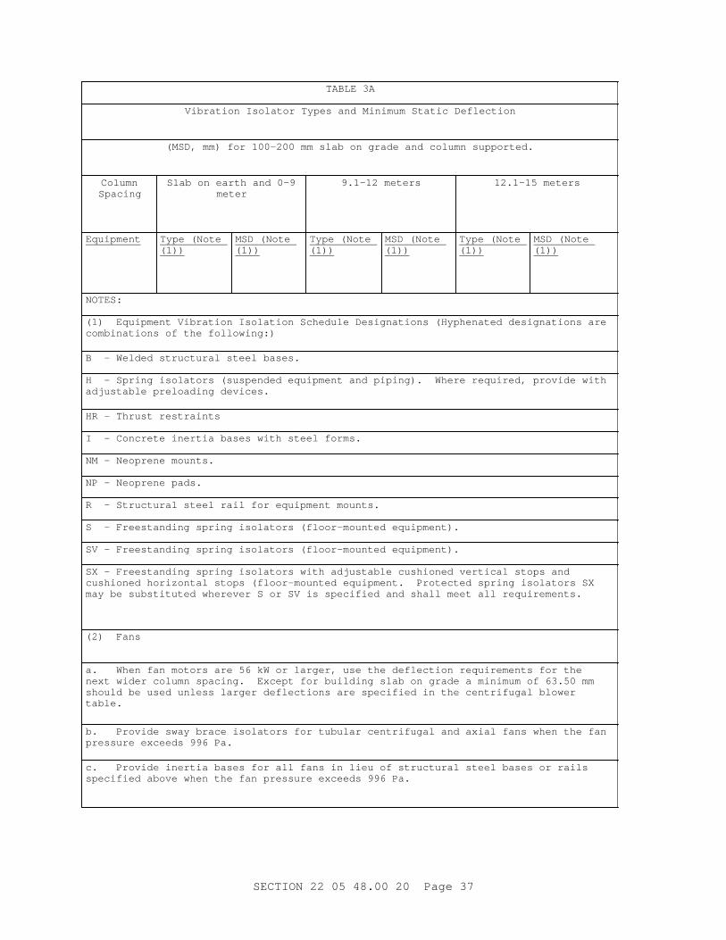
TABLE 3A
Vi br at i on I sol at or Types and Mi ni mum St at i c Def l ect i on
( MSD, mm) f or 100- 200 mm sl ab on gr ade and col umn suppor t ed.
ColumnSpacing
Sl ab on ear t h and 0- 9meter
9. 1- 12 met er s 12. 1- 15 met er s
Equipment Type ( Not e (1))
MSD ( Not e (1))
Type ( Not e (1))
MSD ( Not e (1))
Type ( Not e (1))
MSD ( Not e (1))
NOTES:
( 1) Equi pment Vi br at i on I sol at i on Schedul e Desi gnat i ons ( Hyphenat ed desi gnat i ons ar e combi nat i ons of t he f ol l owi ng: )
B - Wel ded st r uct ur al st eel bases.
H - Spr i ng i sol at or s ( suspended equi pment and pi pi ng) . Wher e r equi r ed, pr ovi de wi t h adj ust abl e pr el oadi ng devi ces.
HR - Thr ust r est r ai nt s
I - Concr et e i ner t i a bases wi t h st eel f or ms.
NM - Neopr ene mount s.
NP - Neopr ene pads.
R - St r uct ur al st eel r ai l f or equi pment mount s.
S - Fr eest andi ng spr i ng i sol at or s ( f l oor - mount ed equi pment ) .
SV - Fr eest andi ng spr i ng i sol at or s ( f l oor - mount ed equi pment ) .
SX - Fr eest andi ng spr i ng i sol at or s wi t h adj ust abl e cushi oned ver t i cal st ops and cushi oned hor i zont al st ops ( f l oor - mount ed equi pment . Pr ot ect ed spr i ng i sol at or s SX may be subst i t ut ed wher ever S or SV i s speci f i ed and shal l meet al l r equi r ement s.
( 2) Fans
a. When f an mot or s ar e 56 kW or l ar ger , use t he def l ect i on r equi r ement s f or t he next wi der col umn spaci ng. Except f or bui l di ng sl ab on gr ade a mi ni mum of 63. 50 mm shoul d be used unl ess l ar ger def l ect i ons ar e speci f i ed i n t he cent r i f ugal bl ower table.
b. Pr ovi de sway br ace i sol at or s f or t ubul ar cent r i f ugal and axi al f ans when t he f an pr essur e exceeds 996 Pa.
c. Pr ovi de i ner t i a bases f or al l f ans i n l i eu of st r uct ur al st eel bases or r ai l s speci f i ed above when t he f an pr essur e exceeds 996 Pa.
SECTI ON 22 05 48. 00 20 Page 37

TABLE 3A
Vi br at i on I sol at or Types and Mi ni mum St at i c Def l ect i on
( MSD, mm) f or 100- 200 mm sl ab on gr ade and col umn suppor t ed.
ColumnSpacing
Sl ab on ear t h and 0- 9meter
9. 1- 12 met er s 12. 1- 15 met er s
Equipment Type ( Not e (1))
MSD ( Not e (1))
Type ( Not e (1))
MSD ( Not e (1))
Type ( Not e (1))
MSD ( Not e (1))
d. Wi t h at t achi ng br acket s, suspensi on spr i ng i sol at or s br i dge bet ween t he st r uct ur e and t he t hr ust - pr oduci ng machi ner y such as hi gh- pr essur e f an. Bot h t ypes H and HR nor mal l y pr ovi de r eact i on i n t ensi on, whi l e t ypes S, SV, and SX nor mal l y pr ovi de r eact i on i n compr essi on. Thr ust r est r ai nt s ar e l ow- cost and ef f ect i ve component s avai l abl e f r om manuf act ur er s. Use t hr ust r est r ai nt s t o el i mi nat e t he need f or or r educe t he magni t ude of i ner t i a mass when t he mass i s onl y used t o r educe t he di spl acement ef f ect s of t he t hr ust .
TABLE 3A
Vi br at i on I sol at or Types and Mi ni mum St at i c Def l ect i on
( MSD, i nches) f or 4- 8 i nch sl ab on gr ade and col umn suppor t ed.
Col umn Spaci ng Sl ab on ear t h and0- 30 f eet
31- 40 f eet 41- 50 f eet
Equipment Type ( Not e ( 1) )
MSD ( Not e (1))
Type ( Not e ( 1) )
MSD ( Not e (1))
Type ( Not e ( 1) )
MSD ( Not e (1))
Absorption Refrigeration Machines
SV-R 1.0 SV-R 1.75 SV-R 2.75
Cent r i f ugal Chi l l er s or Heat Pumps
Her met i c Type SV-B 1.75 SV-B 2.5 SV-B 3.5
Open Type SV-1 1.75 SV-I 2.5 SV-I 3.5
SECTI ON 22 05 48. 00 20 Page 38
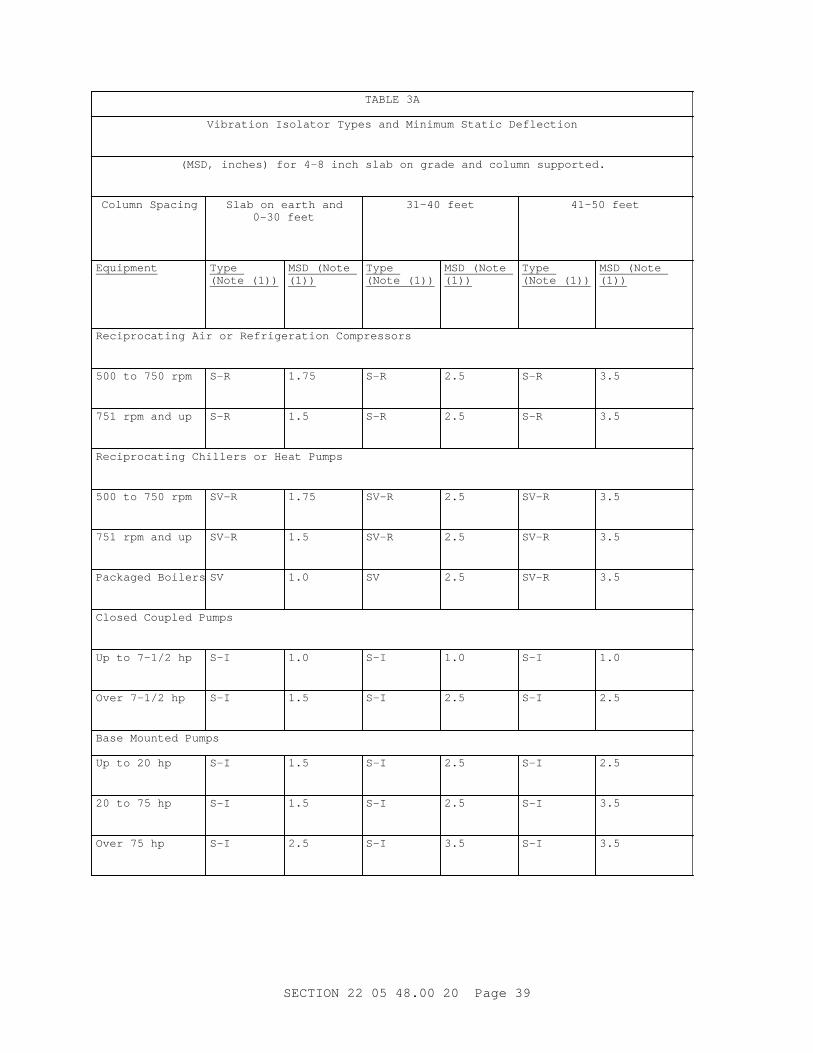
TABLE 3A
Vi br at i on I sol at or Types and Mi ni mum St at i c Def l ect i on
( MSD, i nches) f or 4- 8 i nch sl ab on gr ade and col umn suppor t ed.
Col umn Spaci ng Sl ab on ear t h and0- 30 f eet
31- 40 f eet 41- 50 f eet
Equipment Type ( Not e ( 1) )
MSD ( Not e (1))
Type ( Not e ( 1) )
MSD ( Not e (1))
Type ( Not e ( 1) )
MSD ( Not e (1))
Reci pr ocat i ng Ai r or Ref r i ger at i on Compr essor s
500 t o 750 r pm S-R 1.75 S-R 2.5 S-R 3.5
751 r pm and up S-R 1.5 S-R 2.5 S-R 3.5
Reci pr ocat i ng Chi l l er s or Heat Pumps
500 t o 750 r pm SV-R 1.75 SV-R 2.5 SV-R 3.5
751 r pm and up SV-R 1.5 SV-R 2.5 SV-R 3.5
Packaged Boi l er s SV 1.0 SV 2.5 SV-R 3.5
Cl osed Coupl ed Pumps
Up t o 7- 1/ 2 hp S-I 1.0 S-I 1.0 S-I 1.0
Over 7- 1/ 2 hp S-I 1.5 S-I 2.5 S-I 2.5
Base Mount ed Pumps
Up t o 20 hp S-I 1.5 S-I 2.5 S-I 2.5
20 t o 75 hp S-I 1.5 S-I 2.5 S-I 3.5
Over 75 hp S-I 2.5 S-I 3.5 S-I 3.5
SECTI ON 22 05 48. 00 20 Page 39

TABLE 3A
Vi br at i on I sol at or Types and Mi ni mum St at i c Def l ect i on
( MSD, i nches) f or 4- 8 i nch sl ab on gr ade and col umn suppor t ed.
Col umn Spaci ng Sl ab on ear t h and0- 30 f eet
31- 40 f eet 41- 50 f eet
Equipment Type ( Not e ( 1) )
MSD ( Not e (1))
Type ( Not e ( 1) )
MSD ( Not e (1))
Type ( Not e ( 1) )
MSD ( Not e (1))
Cool i ng Tower s and Evapor at i ve Condenser s
SV wi t h def l ect i ons speci f i ed f or cent r i f ugal bl ower s when spr i ngs ar e suppor t ed on beams. Use sel ect i on l i s t ed f or col umn suppor t ed f l oor s wi t h up t o 30 f oot col umn spaci ng when spr i ngs ar e l ocat ed on col umns or bear i ng wal l s.
Fact or y Assembl ed Ai r Handl i ng Equi pment AH, AC and HV Uni t s ( Not e ( 2) )
Suspended Uni t s
Up t o 5 hp H 1.0 H 1.0 H 1.0
Over 5 hp
Up t o 400 r pm H 1.75 H 1.75 H 1.75
Over 401 r pm H 1.0 H 1.5 H 2.5
Fl oor Mount ed Uni t s
Up t o 5 hp S 1.0 S 1.0 S 1.0
Over 5 hp
Up t o 400 r pm S-R 1.75 S-R 1.75 S-R 2.5
Over 401 r pm S-R 1.0 S-R 1.5 S-R 2.5
Cent r i f ugal Bl ower s
175 - 224 r pm S-B 4.75 S-B 4.75 S-B 4.75
225 - 299 r pm S-B 3.75 S-B 4.75 S-B 4.75
300 - 374 r pm S-B 2.75 S-B 4.5 S-B 4.75
SECTI ON 22 05 48. 00 20 Page 40

TABLE 3A
Vi br at i on I sol at or Types and Mi ni mum St at i c Def l ect i on
( MSD, i nches) f or 4- 8 i nch sl ab on gr ade and col umn suppor t ed.
Col umn Spaci ng Sl ab on ear t h and0- 30 f eet
31- 40 f eet 41- 50 f eet
Equipment Type ( Not e ( 1) )
MSD ( Not e (1))
Type ( Not e ( 1) )
MSD ( Not e (1))
Type ( Not e ( 1) )
MSD ( Not e (1))
375 - 499 r pm S-B 2.5 S-B 3.5 S-B 4.5
Over 500 r pm S-B 1.75 S-B 2.5 S-B 3.5
Tubul ar Cent r i f ugal and Axi al Fans ( Not e ( 2) )
Suspended H wi t h def l ect i on speci f i ed f or cent r i f ugal bl ower s
Fl oor Mount ed Ar r angement s 1 & 9
S- B wi t h def l ect i ons speci f i ed f or cent r i f ugal bl ower s
Ut i l i t y Fans ( Not e ( 2) )
Suspended H wi t h def l ect i ons speci f i ed f or cent r i f ugal bl ower s but not t o exceed 2. 75 i nches
Floor-Mounted S- R wi t h def l ect i ons not speci f i ed f or cent r i f ugal bl ower s but not t o exceed 2. 75 i nches
Hi gh Pr essur e Fans ( 6 I nch Wat er - Col umn St at i c Pr essur e) and Ot her Machi ner i es Pr oduci ng Thr ust ( Not e ( 2) )
HR r ecommended f or mi ni mi zi ng undesi r abl e t hr ust ef f ect s
I nt er nal Combust i on Engi nes and Engi ne Dr i ven Equi p
750 r pm and over
S 1.5 S 2.5 S 3.5
Di mmer Banks and Tr ansf or mer s
Up t o 1000 l bs. NM 0.35 NM 0.35 NM 3.5
Over 1000 l bs. SV 1.0 SV 1.0 SV 1.0
NOTES:
SECTI ON 22 05 48. 00 20 Page 41

TABLE 3A
Vi br at i on I sol at or Types and Mi ni mum St at i c Def l ect i on
( MSD, i nches) f or 4- 8 i nch sl ab on gr ade and col umn suppor t ed.
Col umn Spaci ng Sl ab on ear t h and0- 30 f eet
31- 40 f eet 41- 50 f eet
Equipment Type ( Not e ( 1) )
MSD ( Not e (1))
Type ( Not e ( 1) )
MSD ( Not e (1))
Type ( Not e ( 1) )
MSD ( Not e (1))
( 1) Equi pment Vi br at i on I sol at i on Schedul e Desi gnat i ons ( Hyphenat ed desi gnat i ons ar e combi nat i ons of t he f ol l owi ng: )
B - Wel ded st r uct ur al st eel bases.
H - Spr i ng i sol at or s ( suspended equi pment and pi pi ng) . Wher e r equi r ed, pr ovi de wi t h adj ust abl e pr el oadi ng devi ces.
HR - Thr ust r est r ai nt s
I - Concr et e i ner t i a bases wi t h st eel f or ms.
NM - Neopr ene mount s.
NP - Neopr ene pads.
R - St r uct ur al st eel r ai l f or equi pment mount s.
S - Fr eest andi ng spr i ng i sol at or s ( f l oor - mount ed equi pment ) .
SV - Fr eest andi ng spr i ng i sol at or s ( f l oor - mount ed equi pment ) .
SX - Fr eest andi ng spr i ng i sol at or s wi t h adj ust abl e cushi oned ver t i cal st ops and cushi oned hor i zont al st ops ( f l oor - mount ed equi pment . Pr ot ect ed spr i ng i sol at or s SX may be subst i t ut ed wher ever S or SV i s speci f i ed and shal l meet al l r equi r ement s.
( 2) Fans
a. When f an mot or s ar e 75 hp or l ar ger , use t he def l ect i on r equi r ement s f or t he next wi der col umn spaci ng. Except f or bui l di ng sl ab on gr ade a mi ni mum of 2. 5 i nches shoul d be used unl ess l ar ger def l ect i ons ar e speci f i ed i n t he cent r i f ugal bl ower table.
b. Pr ovi de sway br ace i sol at or s f or t ubul ar cent r i f ugal and axi al f ans when t he f an pr essur e exceeds 4 i nches wat er col umn.
c. Pr ovi de i ner t i a bases f or al l f ans i n l i eu of st r uct ur al st eel bases or r ai l s speci f i ed above when t he f an pr essur e exceeds 4 i nches wat er col umn.
SECTI ON 22 05 48. 00 20 Page 42

TABLE 3A
Vi br at i on I sol at or Types and Mi ni mum St at i c Def l ect i on
( MSD, i nches) f or 4- 8 i nch sl ab on gr ade and col umn suppor t ed.
Col umn Spaci ng Sl ab on ear t h and0- 30 f eet
31- 40 f eet 41- 50 f eet
Equipment Type ( Not e ( 1) )
MSD ( Not e (1))
Type ( Not e ( 1) )
MSD ( Not e (1))
Type ( Not e ( 1) )
MSD ( Not e (1))
d. Wi t h at t achi ng br acket s, suspensi on spr i ng i sol at or s br i dge bet ween t he st r uct ur e and t he t hr ust - pr oduci ng machi ner y such as hi gh- pr essur e f an. Bot h t ypes H and HR nor mal l y pr ovi de r eact i on i n t ensi on, whi l e t ypes S, SV, and SX nor mal l y pr ovi de r eact i on i n compr essi on. Thr ust r est r ai nt s ar e l ow- cost and ef f ect i ve component s avai l abl e f r om manuf act ur er s. Use t hr ust r est r ai nt s t o el i mi nat e t he need f or or r educe t he magni t ude of i ner t i a mass when t he mass i s onl y used t o r educe t he di spl acement ef f ect s of t he t hr ust .
Uni t i zed assembl i es such as chi l l er s wi t h evapor at or and condenser , and t op mount ed cent r i f ugal compr essor or uni t i zed absor pt i on r ef r i ger at i on machi nes, st r uct ur al l y desi gned wi t h end suppor t s, may be mount ed on st eel r ai l s and spr i ngs i n l i eu of st eel bases and spr i ngs. Wher e t he s l ab or deck i s l ess t han 100 mm 4 i nches t hi ck, pr ovi de spr i ng i sol at i on uni t s wi t h t he def l ect i on doubl e t hat of t he v i br at i on i sol at i on schedul e, up t o a maxi mum st at i c def l ect i on of 127 mm 5 i nches.
3. 1. 7. 6 Roof and Upper Fl oor Mount ed Machi ner y
**************************************************************************NOTE: The f ol l owi ng t abl e ser ves onl y as a gui del i ne. Del et e i t ems t hat ar e not appl i cabl e.
**************************************************************************
SECTI ON 22 05 48. 00 20 Page 43

TABLE 3A
Vi br at i on I sol at or Types and Mi ni mum St at i c Def l ect i on
( MSD, mm) f or 100- 200 mm sl ab on gr ade and col umn suppor t ed.
Col umn Spaci ng Sl ab on ear t h and 0- 9meter
9. 1- 12 met er s 12. 1- 15 met er s
Equipment Type ( Not e (1))
MSD ( Not e (1))
Type ( Not e (1))
MSD ( Not e (1))
Type ( Not e ( 1) )
MSD ( Not e (1))
Absorption Refrigeration Machines
SV-R 25.40 SV-R 44.45 SV-R 69.85
Cent r i f ugal Chi l l er s or Heat Pumps
Her met i c Type SV-B 44.45 SV-B 63.50 SV-B 88.90
Open Type SV-1 44.45 SV-I 63.50 SV-I 88.90
Reci pr ocat i ng Ai r or Ref r i ger at i on Compr essor s
500 t o 750 r pm S-R 44.45 S-R 63.50 S-R 88.90
751 r pm and up S-R 38.10 S-R 63.50 S-R 88.90
Reci pr ocat i ng Chi l l er s or Heat Pumps
500 t o 750 r pm SV-R 44.45 SV-R 63.50 SV-R 88.90
751 r pm and up SV-R 38.10 SV-R 63.50 SV-R 88.90
Packaged Boilers
SV 25.40 SV 63.50 SV-R 88.90
Cl osed Coupl ed Pumps
Up t o 5 1/ 2 kW S-I 25.40 S-I 25.40 S-I 25.40
Over 5 1/ 2 kW S-I 38.10 S-I 63.50 S-I 63.50
Base Mount ed Pumps
SECTI ON 22 05 48. 00 20 Page 44

TABLE 3A
Vi br at i on I sol at or Types and Mi ni mum St at i c Def l ect i on
( MSD, mm) f or 100- 200 mm sl ab on gr ade and col umn suppor t ed.
Col umn Spaci ng Sl ab on ear t h and 0- 9meter
9. 1- 12 met er s 12. 1- 15 met er s
Equipment Type ( Not e (1))
MSD ( Not e (1))
Type ( Not e (1))
MSD ( Not e (1))
Type ( Not e ( 1) )
MSD ( Not e (1))
Up t o 15 kW S-I 38.10 S-I 63.50 S-I 63.50
15 t o 56 kW S-I 38.10 S-I 63.50 S-I 88.90
Over 56 kW S-I 63.50 S-I 88.90 S-I 88.90
Cool i ng Tower s and Evapor at i ve Condenser s
SV wi t h def l ect i ons speci f i ed f or cent r i f ugal bl ower s when spr i ngs ar e suppor t ed on beams. Use def l ect i on l i s t ed f or col umn suppor t ed f l oor s wi t h up t o 9 met er s col umn spaci ng when spr i ngs ar e l ocat ed on col umns or bear i ng wal l s.
Fact or y Assembl ed Ai r Handl i ng Equi pment AH, AC and HV Uni t s ( Not e ( 2) )
Suspended Uni t s
Up t o 3 3/ 4 kW H 25.40 H 25.40 H 25.40
Over 3 3/ 4 kW
Up t o 400 r pm H 44.45 H 44.45 H 44.45
Over 401 r pm H 25.40 H 38.10 H 63.50
Fl oor Mount ed Uni t s
Up t o 3 3/ 4 kW S 25.40 S 25.40 S 25.40
Over 3 3/ 4 kW
Up t o 400 r pm S-R 44.45 S-R 44.45 S-R 63.50
Over 401 r pm S-R 25.40 S-R 38.10 S-R 63.50
Cent r i f ugal Bl ower s
SECTI ON 22 05 48. 00 20 Page 45

TABLE 3A
Vi br at i on I sol at or Types and Mi ni mum St at i c Def l ect i on
( MSD, mm) f or 100- 200 mm sl ab on gr ade and col umn suppor t ed.
Col umn Spaci ng Sl ab on ear t h and 0- 9meter
9. 1- 12 met er s 12. 1- 15 met er s
Equipment Type ( Not e (1))
MSD ( Not e (1))
Type ( Not e (1))
MSD ( Not e (1))
Type ( Not e ( 1) )
MSD ( Not e (1))
175 - 224 r pm S-B 120.65 S-B 120.65 S-B 120.65
225 - 299 r pm S-B 95.25 S-B 120.65 S-B 120.65
300 - 374 r pm S-B 69.85 S-B 114.30 S-B 120.65
375 - 499 r pm S-B 63.50 S-B 88.90 S-B 114.30
Over 500 r pm S-B 44.45 S-B 63.50 S-B 88.90
Tubul ar Cent r i f ugal and Axi al Fans ( Not e ( 2) )
Suspended H wi t h def l ect i on speci f i ed f or cent r i f ugal bl ower s
Fl oor Mount ed Ar r angement s 1 & 9
S- B wi t h def l ect i ons speci f i ed f or cent r i f ugal bl ower s
Ut i l i t y Fans ( Not e ( 2) )
Suspended H wi t h def l ect i ons speci f i ed f or cent r i f ugal bl ower s but not t o exceed 69. 85 mm
Floor-Mounted S- R wi t h def l ect i ons not speci f i ed f or cent r i f ugal bl ower s but not t o exceed 69. 85 mm
Hi gh Pr essur e Fans ( Over 1494 Pa St at i c Pr essur e) and Ot her Machi ner i es Pr oduci ng Thr ust ( Not e ( 2) )
HR r ecommended f or mi ni mi zi ng undesi r abl e t hr ust ef f ect s
I nt er nal Combust i on Engi nes and Engi ne Dr i ven Equi p
750 r pm and over
S 38.10 S 63.50 S 88.90
Di mmer Banks and Tr ansf or mer s
SECTI ON 22 05 48. 00 20 Page 46

TABLE 3A
Vi br at i on I sol at or Types and Mi ni mum St at i c Def l ect i on
( MSD, mm) f or 100- 200 mm sl ab on gr ade and col umn suppor t ed.
Col umn Spaci ng Sl ab on ear t h and 0- 9meter
9. 1- 12 met er s 12. 1- 15 met er s
Equipment Type ( Not e (1))
MSD ( Not e (1))
Type ( Not e (1))
MSD ( Not e (1))
Type ( Not e ( 1) )
MSD ( Not e (1))
Up t o 454 kg NM 8.89 NM 8.89 NM 88.90
Over 454 kg SV 25.40 SV 25.40 SV 25.40
NOTES:
( 1) Equi pment Vi br at i on I sol at i on Schedul e Desi gnat i ons ( Hyphenat ed desi gnat i ons ar e combi nat i ons of t he f ol l owi ng: )
B - Wel ded st r uct ur al st eel bases.
H - Spr i ng i sol at or s ( suspended equi pment and pi pi ng) . Wher e r equi r ed, pr ovi de wi t h adj ust abl e pr el oadi ng devi ces.
HR - Thr ust r est r ai nt s
I - Concr et e i ner t i a bases wi t h st eel f or ms.
NM - Neopr ene mount s.
NP - Neopr ene pads.
R - St r uct ur al st eel r ai l f or equi pment mount s.
S - Fr eest andi ng spr i ng i sol at or s ( f l oor - mount ed equi pment ) .
SV - Fr eest andi ng spr i ng i sol at or s ( f l oor - mount ed equi pment ) .
SX - Fr eest andi ng spr i ng i sol at or s wi t h adj ust abl e cushi oned ver t i cal st ops and cushi oned hor i zont al st ops ( f l oor - mount ed equi pment . Pr ot ect ed spr i ng i sol at or s SX may be subst i t ut ed wher ever S or SV i s speci f i ed and shal l meet al l r equi r ement s.
( 2) Fans
a. When f an mot or s ar e 56 kW or l ar ger , use t he def l ect i on r equi r ement s f or t he next wi der col umn spaci ng. Except f or bui l di ng sl ab on gr ade a mi ni mum of 63. 50 mm shoul d be used unl ess l ar ger def l ect i ons ar e speci f i ed i n t he cent r i f ugal bl ower table.
b. Pr ovi de sway br ace i sol at or s f or t ubul ar cent r i f ugal and axi al f ans when t he f an pr essur e exceeds 996 Pa.
SECTI ON 22 05 48. 00 20 Page 47

TABLE 3A
Vi br at i on I sol at or Types and Mi ni mum St at i c Def l ect i on
( MSD, mm) f or 100- 200 mm sl ab on gr ade and col umn suppor t ed.
Col umn Spaci ng Sl ab on ear t h and 0- 9meter
9. 1- 12 met er s 12. 1- 15 met er s
Equipment Type ( Not e (1))
MSD ( Not e (1))
Type ( Not e (1))
MSD ( Not e (1))
Type ( Not e ( 1) )
MSD ( Not e (1))
c. Pr ovi de i ner t i a bases f or al l f ans i n l i eu of st r uct ur al st eel bases or r ai l s speci f i ed above when t he f an pr essur e exceeds 996 Pa.
d. Wi t h at t achi ng br acket s, suspensi on spr i ng i sol at or s br i dge bet ween t he st r uct ur e and t he t hr ust - pr oduci ng machi ner y such as hi gh- pr essur e f an. Bot h t ypes H and HR nor mal l y pr ovi de r eact i on i n t ensi on, whi l e t ypes S, SV, and SX nor mal l y pr ovi de r eact i on i n compr essi on. Thr ust r est r ai nt s ar e l ow- cost and ef f ect i ve component s avai l abl e f r om manuf act ur er s. Use t hr ust r est r ai nt s t o el i mi nat e t he need f or or r educe t he magni t ude of i ner t i a mass when t he mass i s onl y used t o r educe t he di spl acement ef f ect s of t he t hr ust .
TABLE 3A
Vi br at i on I sol at or Types and Mi ni mum St at i c Def l ect i on
( MSD, i nches) f or 4- 8 i nch sl ab on gr ade and col umn suppor t ed.
ColumnSpacing
Sl ab on ear t h and 0- 30feet
31- 40 f eet 41- 50 f eet
Equipment Type ( Not e (1))
MSD ( Not e (1))
Type ( Not e (1))
MSD ( Not e (1))
Type ( Not e (1))
MSD ( Not e (1))
Absorption Refrigeration Machines
SV-R 1.0 SV-R 1.75 SV-R 2.75
Cent r i f ugal Chi l l er s or Heat Pumps
Hermetic Type
SV-B 1.75 SV-B 2.5 SV-B 3.5
Open Type SV-1 1.75 SV-I 2.5 SV-I 3.5
SECTI ON 22 05 48. 00 20 Page 48

TABLE 3A
Vi br at i on I sol at or Types and Mi ni mum St at i c Def l ect i on
( MSD, i nches) f or 4- 8 i nch sl ab on gr ade and col umn suppor t ed.
ColumnSpacing
Sl ab on ear t h and 0- 30feet
31- 40 f eet 41- 50 f eet
Equipment Type ( Not e (1))
MSD ( Not e (1))
Type ( Not e (1))
MSD ( Not e (1))
Type ( Not e (1))
MSD ( Not e (1))
Reci pr ocat i ng Ai r or Ref r i ger at i on Compr essor s
500 t o 750 rpm
S-R 1.75 S-R 2.5 S-R 3.5
751 r pm and up
S-R 1.5 S-R 2.5 S-R 3.5
Reci pr ocat i ng Chi l l er s or Heat Pumps
500 t o 750 rpm
SV-R 1.75 SV-R 2.5 SV-R 3.5
751 r pm and up
SV-R 1.5 SV-R 2.5 SV-R 3.5
Packaged Boilers
SV 1.0 SV 2.5 SV-R 3.5
Cl osed Coupl ed Pumps
Up t o 7- 1/ 2 hp
S-I 1.0 S-I 1.0 S-I 1.0
Over 7- 1/ 2 hp
S-I 1.5 S-I 2.5 S-I 2.5
Base Mount ed Pumps
Up t o 20 hp S-I 1.5 S-I 2.5 S-I 2.5
20 t o 75 hp S-I 1.5 S-I 2.5 S-I 3.5
Over 75 hp S-I 2.5 S-I 3.5 S-I 3.5
SECTI ON 22 05 48. 00 20 Page 49
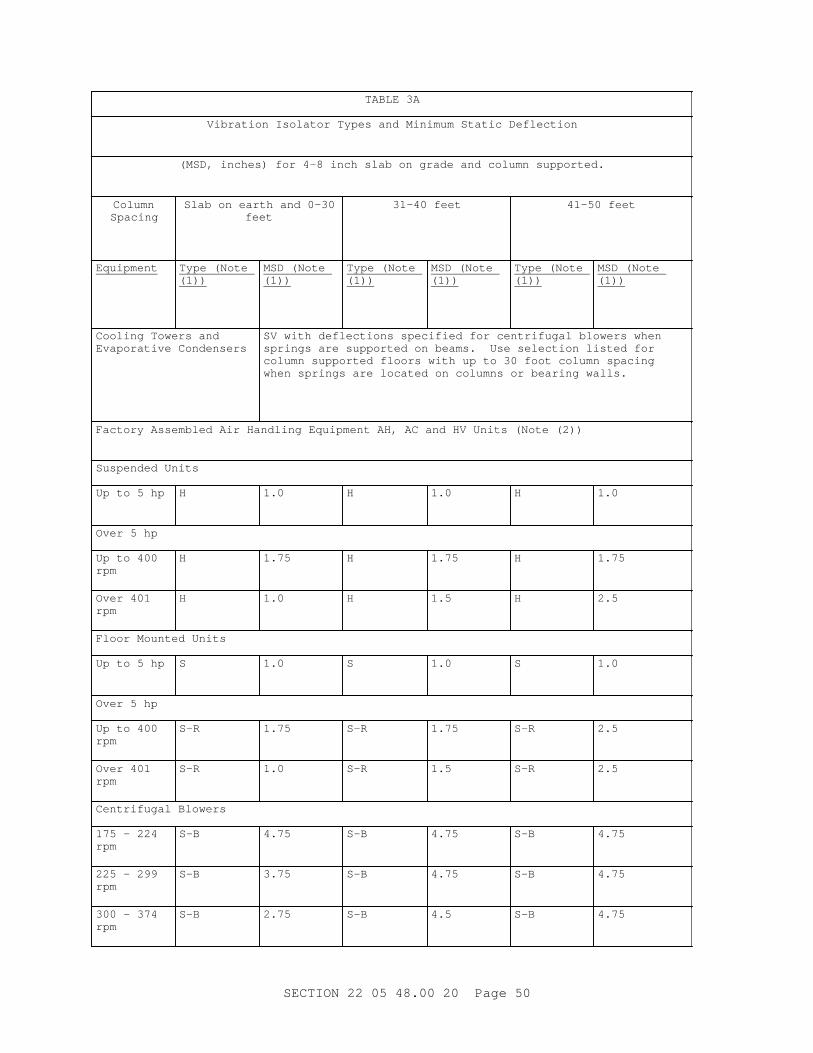
TABLE 3A
Vi br at i on I sol at or Types and Mi ni mum St at i c Def l ect i on
( MSD, i nches) f or 4- 8 i nch sl ab on gr ade and col umn suppor t ed.
ColumnSpacing
Sl ab on ear t h and 0- 30feet
31- 40 f eet 41- 50 f eet
Equipment Type ( Not e (1))
MSD ( Not e (1))
Type ( Not e (1))
MSD ( Not e (1))
Type ( Not e (1))
MSD ( Not e (1))
Cool i ng Tower s and Evapor at i ve Condenser s
SV wi t h def l ect i ons speci f i ed f or cent r i f ugal bl ower s when spr i ngs ar e suppor t ed on beams. Use sel ect i on l i s t ed f or col umn suppor t ed f l oor s wi t h up t o 30 f oot col umn spaci ng when spr i ngs ar e l ocat ed on col umns or bear i ng wal l s.
Fact or y Assembl ed Ai r Handl i ng Equi pment AH, AC and HV Uni t s ( Not e ( 2) )
Suspended Uni t s
Up t o 5 hp H 1.0 H 1.0 H 1.0
Over 5 hp
Up t o 400 rpm
H 1.75 H 1.75 H 1.75
Over 401 rpm
H 1.0 H 1.5 H 2.5
Fl oor Mount ed Uni t s
Up t o 5 hp S 1.0 S 1.0 S 1.0
Over 5 hp
Up t o 400 rpm
S-R 1.75 S-R 1.75 S-R 2.5
Over 401 rpm
S-R 1.0 S-R 1.5 S-R 2.5
Cent r i f ugal Bl ower s
175 - 224 rpm
S-B 4.75 S-B 4.75 S-B 4.75
225 - 299 rpm
S-B 3.75 S-B 4.75 S-B 4.75
300 - 374 rpm
S-B 2.75 S-B 4.5 S-B 4.75
SECTI ON 22 05 48. 00 20 Page 50

TABLE 3A
Vi br at i on I sol at or Types and Mi ni mum St at i c Def l ect i on
( MSD, i nches) f or 4- 8 i nch sl ab on gr ade and col umn suppor t ed.
ColumnSpacing
Sl ab on ear t h and 0- 30feet
31- 40 f eet 41- 50 f eet
Equipment Type ( Not e (1))
MSD ( Not e (1))
Type ( Not e (1))
MSD ( Not e (1))
Type ( Not e (1))
MSD ( Not e (1))
375 - 499 rpm
S-B 2.5 S-B 3.5 S-B 4.5
Over 500 rpm
S-B 1.75 S-B 2.5 S-B 3.5
Tubul ar Cent r i f ugal and Axi al Fans ( Not e ( 2) )
Suspended H wi t h def l ect i on speci f i ed f or cent r i f ugal bl ower s
Fl oor Mount ed Ar r angement s 1 & 9
S- B wi t h def l ect i ons speci f i ed f or cent r i f ugal bl ower s
Ut i l i t y Fans ( Not e ( 2) )
Suspended H wi t h def l ect i ons speci f i ed f or cent r i f ugal bl ower s but not t o exceed 2. 75 i nches
Floor-Mounted S- R wi t h def l ect i ons not speci f i ed f or cent r i f ugal bl ower s but not t o exceed 2. 75 i nches
Hi gh Pr essur e Fans ( 6 I nch Wat er - Col umn St at i c Pr essur e) and Ot her Machi ner i es Pr oduci ng Thr ust ( Not e (2))
HR r ecommended f or mi ni mi zi ng undesi r abl e t hr ust ef f ect s
I nt er nal Combust i on Engi nes and Engi ne Dr i ven Equi p
750 r pm and over
S 1.5 S 2.5 S 3.5
Di mmer Banks and Tr ansf or mer s
Up t o 1000 lbs.
NM 0.35 NM 0.35 NM 3.5
Over 1000 lbs.
SV 1.0 SV 1.0 SV 1.0
NOTES:
SECTI ON 22 05 48. 00 20 Page 51

TABLE 3A
Vi br at i on I sol at or Types and Mi ni mum St at i c Def l ect i on
( MSD, i nches) f or 4- 8 i nch sl ab on gr ade and col umn suppor t ed.
ColumnSpacing
Sl ab on ear t h and 0- 30feet
31- 40 f eet 41- 50 f eet
Equipment Type ( Not e (1))
MSD ( Not e (1))
Type ( Not e (1))
MSD ( Not e (1))
Type ( Not e (1))
MSD ( Not e (1))
( 1) Equi pment Vi br at i on I sol at i on Schedul e Desi gnat i ons ( Hyphenat ed desi gnat i ons ar e combi nat i ons of t he f ol l owi ng: )
B - Wel ded st r uct ur al st eel bases.
H - Spr i ng i sol at or s ( suspended equi pment and pi pi ng) . Wher e r equi r ed, pr ovi de wi t h adj ust abl e pr el oadi ng devi ces.
HR - Thr ust r est r ai nt s
I - Concr et e i ner t i a bases wi t h st eel f or ms.
NM - Neopr ene mount s.
NP - Neopr ene pads.
R - St r uct ur al st eel r ai l f or equi pment mount s.
S - Fr eest andi ng spr i ng i sol at or s ( f l oor - mount ed equi pment ) .
SV - Fr eest andi ng spr i ng i sol at or s ( f l oor - mount ed equi pment ) .
SX - Fr eest andi ng spr i ng i sol at or s wi t h adj ust abl e cushi oned ver t i cal st ops and cushi oned hor i zont al st ops ( f l oor - mount ed equi pment . Pr ot ect ed spr i ng i sol at or s SX may be subst i t ut ed wher ever S or SV i s speci f i ed and shal l meet al l r equi r ement s.
( 2) Fans
a. When f an mot or s ar e 75 hp or l ar ger , use t he def l ect i on r equi r ement s f or t he next wi der col umn spaci ng. Except f or bui l di ng sl ab on gr ade a mi ni mum of 2. 5 i nches shoul d be used unl ess l ar ger def l ect i ons ar e speci f i ed i n t he cent r i f ugal bl ower table.
b. Pr ovi de sway br ace i sol at or s f or t ubul ar cent r i f ugal and axi al f ans when t he f an pr essur e exceeds 4 i nches wat er col umn.
c. Pr ovi de i ner t i a bases f or al l f ans i n l i eu of st r uct ur al st eel bases or r ai l s speci f i ed above when t he f an pr essur e exceeds 4 i nches wat er col umn.
SECTI ON 22 05 48. 00 20 Page 52

TABLE 3A
Vi br at i on I sol at or Types and Mi ni mum St at i c Def l ect i on
( MSD, i nches) f or 4- 8 i nch sl ab on gr ade and col umn suppor t ed.
ColumnSpacing
Sl ab on ear t h and 0- 30feet
31- 40 f eet 41- 50 f eet
Equipment Type ( Not e (1))
MSD ( Not e (1))
Type ( Not e (1))
MSD ( Not e (1))
Type ( Not e (1))
MSD ( Not e (1))
d. Wi t h at t achi ng br acket s, suspensi on spr i ng i sol at or s br i dge bet ween t he st r uct ur e and t he t hr ust - pr oduci ng machi ner y such as hi gh- pr essur e f an. Bot h t ypes H and HR nor mal l y pr ovi de r eact i on i n t ensi on, whi l e t ypes S, SV, and SX nor mal l y pr ovi de r eact i on i n compr essi on. Thr ust r est r ai nt s ar e l ow- cost and ef f ect i ve component s avai l abl e f r om manuf act ur er s. Use t hr ust r est r ai nt s t o el i mi nat e t he need f or or r educe t he magni t ude of i ner t i a mass when t he mass i s onl y used t o r educe t he di spl acement ef f ect s of t he t hr ust .
TABLE 1B
Cl ass I I Vi br at i on I sol at or Types and Mi ni mum St at i c Def l ect i on
( MSD, mm) f or basement s bel ow gr ade and f l oor s l abs on ear t h
Equipment Type ( Not e ( 1) ) MSD
Absor pt i on Ref r i ger at i on Machines
NP 6.35
NM 8.89
Cent r i f ugal Chi l l er s or Heat Pumps
Her met i c Type NP 6.35
NM 8.89
Open Type NM-I 8.89
Reci pr ocat i ng Ai r or Ref r i ger at i on Compr essor s
500 t o 750 r pm S 25.40
751 r pm and up S 25.40
Reci pr ocat i ng Chi l l er s or Heat Pumps
500 t o 750 r pm SV 25.40
751 r pm and up SV 25.40
Packaged Boi l er s NP 6.35
NM 8.89
Pumps
Cl osed Coupl ed NP 6.35
SECTI ON 22 05 48. 00 20 Page 53

TABLE 1B
Cl ass I I Vi br at i on I sol at or Types and Mi ni mum St at i c Def l ect i on
( MSD, mm) f or basement s bel ow gr ade and f l oor s l abs on ear t h
Equipment Type ( Not e ( 1) ) MSD
Up t o 5 1/ 2 kW NM 8.89
Over 5 1/ 2 kW S-I 25.40
Base Mount ed
Up t o 15 kW S-I 25.40
15 t o 56 kW S-I 25.40
Over 56 kW S-I 25.40
Cool i ng Tower s and Evapor at i ve Condenser s
NP 6.35
NM 8.89
Fact or y Assembl ed Ai r Handl i ng Equi pment AH, AC and HV Uni t s ( Not e ( 2) )
Suspended Uni t s
Up t o 3 3/ 4 kW H 25.40
Over 3 3/ 4 kW
Up t o 400 r pm H 44.45
Over 401 r pm H 25.40
Fl oor Mount ed Uni t s
Up t o 3 3/ 4 kW NP 6.35
NM 8.89
Over 3 3/ 4 kW
Up t o 400 r pm NM 8.89
Over 401 r pm NM 8.89
Cent r i f ugal Bl ower s
175 - 224 r pm NM-B 8.89
225 - 299 r pm NM-B 8.89
300 - 374 r pm NM-B 8.89
375 - 499 r pm NM-B 8.89
Over 500 r pm NM-B 8.89
Tubul ar Cent r i f ugal and Axi al Fans ( Not e ( 2) )
Suspended H wi t h def l ect i ons speci f i ed f or cent r i f ugal bl ower s
Fl oor Mount ed Ar r angement s 1 & 9
NM 8.89
Ut i l i t y Fans ( Not e ( 2) )
SECTI ON 22 05 48. 00 20 Page 54

TABLE 1B
Cl ass I I Vi br at i on I sol at or Types and Mi ni mum St at i c Def l ect i on
( MSD, mm) f or basement s bel ow gr ade and f l oor s l abs on ear t h
Equipment Type ( Not e ( 1) ) MSD
Suspended and cent r i f ugal H wi t h def l ect i ons speci f i ed f or
Floor-Mounted NM 8.89
Hi gh Pr essur e Fans ( Over 1494 Pa St at i c Pr essur e) and Ot her Machi ner i es Pr oduci ng Thr ust ( Not e ( 2) )
HR r ecommended f or mi ni mi zi ng undesi r abl e t hr ust ef f ect s
I nt er nal Combust i on Engi nes and Engi ne Dr i ven Equi p
750 r pm and over S 25.40
Di mmer Banks and Tr ansf or mer s
Up t o 454 kg NP 6.35
NM 8.89
Over 454 kg SV 25.40
NOTES: Not e ( 1) and Not e ( 2) ar e same as f or TABLE 3A.
TABLE 3B
Cl ass I I Vi br at i on I sol at or Types and Mi ni mum St at i c Def l ect i on
( MSD, i nches) f or basement s bel ow gr ade and f l oor s l abs on ear t h
Equipment Type ( Not e ( 1) ) MSD
Absor pt i on Ref r i ger at i on Machines
NP 0.25
NM 0.35
Cent r i f ugal Chi l l er s or Heat Pumps
Her met i c Type NP 0.25
NM 0.35
Open Type NM-I 0.35
Reci pr ocat i ng Ai r or Ref r i ger at i on Compr essor s
500 t o 750 r pm S 1.0
751 r pm and up S 1.0
Reci pr ocat i ng Chi l l er s or Heat Pumps
500 t o 750 r pm SV 1.0
751 r pm and up SV 1.0
SECTI ON 22 05 48. 00 20 Page 55

TABLE 3B
Cl ass I I Vi br at i on I sol at or Types and Mi ni mum St at i c Def l ect i on
( MSD, i nches) f or basement s bel ow gr ade and f l oor s l abs on ear t h
Equipment Type ( Not e ( 1) ) MSD
Packaged Boi l er s NP 0.25
NM 0.35
Pumps
Cl osed Coupl ed NP 0.25
Up t o 7 1/ 2 hp NM 0.35
Over 7 1/ 2 hp S-I 1.0
Base Mount ed
Up t o 20 hp S-I 1.0
20 t o 75 hp S-I 1.0
Over 75 hp S-I 1.0
Cool i ng Tower s and Evapor at i ve Condenser s
NP 0.25
NM 0.35
Fact or y Assembl ed Ai r Handl i ng Equi pment AH, AC and HV Uni t s ( Not e ( 2) )
Suspended Uni t s
Up t o 5 hp H 1.0
Over 5 hp
Up t o 400 r pm H 1.75
Over 401 r pm H 1.0
Fl oor Mount ed Uni t s
Up t o 5 hp NP 0.25
NM 0.35
Over 5 hp
Up t o 400 r pm NM 0.35
Over 401 r pm NM 0.35
Cent r i f ugal Bl ower s
175 - 224 r pm NM-B 0.35
225 - 299 r pm NM-B 0.35
300 - 374 r pm NM-B 0.35
375 - 499 r pm NM-B 0.35
Over 500 r pm NM-B 0.35
Tubul ar Cent r i f ugal and Axi al Fans ( Not e ( 2) )
SECTI ON 22 05 48. 00 20 Page 56

TABLE 3B
Cl ass I I Vi br at i on I sol at or Types and Mi ni mum St at i c Def l ect i on
( MSD, i nches) f or basement s bel ow gr ade and f l oor s l abs on ear t h
Equipment Type ( Not e ( 1) ) MSD
Suspended H wi t h def l ect i ons speci f i ed f or cent r i f ugal bl ower s
Fl oor Mount ed Ar r angement s 1 & 9
NM 0.35
Ut i l i t y Fans ( Not e ( 2) )
Suspended and cent r i f ugal H wi t h def l ect i ons speci f i ed f or
Floor-Mounted NM 0.35
Hi gh Pr essur e Fans ( Over 6 I nch Wat er - Col umn St at i c Pr essur e) and Ot her Machi ner i es Pr oduci ng Thr ust ( Not e (2))
HR r ecommended f or mi ni mi zi ng undesi r abl e t hr ust ef f ect s
I nt er nal Combust i on Engi nes and Engi ne Dr i ven Equi p
750 r pm and over S 1.0
Di mmer Banks and Tr ansf or mer s
Up t o 1000 l bs. NP 0.25
NM 0.35
Over 1000 l bs. SV 1.0
NOTES: Not e ( 1) and Not e ( 2) ar e same as f or TABLE 3A.
On t he r oof or upper f l oor s, mount machi ner y on i sol at or s wi t h ver t i cal st ops. Rest i sol at or s on beams or st r uct ur es desi gned and i nst al l ed i n accor dance wi t h t he SMACNA 1793, Pl at e 61.
3. 1. 8 [ Pi pi ng] [ and] [ Hi gh Pr essur e Duct wor k]
Pr ovi de v i br at i on i sol at i on f or [ pi pi ng] [ and] [ hi gh pr essur e duct wor k wi t h over 1494 Pa 6 i nches wat er col umn] . The i sol at or def l ect i ons shal l be equal t o or gr eat er t han t he st at i c def l ect i on of t he v i br at i on i sol at or s pr ovi ded f or t he connect ed machi ner y as f ol l ows:
[ 3. 1. 8. 1 Hi gh Pr essur e Duct wor k
For a di st ance of 15 met er s 50 f eet f r om f ans, exhaust er s and bl ower s.
] 3. 1. 8. 2 Pi pi ng Connect ed t o Vi br at i on I sol at ed Machi ner y
For a di st ance of 15 met er s 50 f eet or 50 pi pe di amet er s, whi chever i s greater.
SECTI ON 22 05 48. 00 20 Page 57

3. 1. 8. 3 St eam Pr essur e Reduci ng Val ves
Connect ed pi pi ng f or a di st ance of 15 met er s 50 f eet or 50 pi pe di amet er s, whi chever i s gr eat er .
3. 1. 8. 4 Condenser Wat er
For t he f ul l l engt h of t he pi pi ng.
3. 1. 8. 5 Chi l l ed, Hot , and Dual Temper at ur e Pi pi ng
For r i ser s f r om pumps and f or t he f i r st 6 met er s 20 f eet of t he br anch connect i on of t he mai n suppl y and r et ur n pi pi ng at each f l oor .
3. 1. 9 Wat er and St eam Di st r i but i on Pi pi ng Appl i cat i on
Resi l i ent l y suppor t pi pi ng wi t h combi nat i on spr i ng and neopr ene i sol at i on hanger s. Pr ovi de spr i ng el ement s wi t h 16 mm 5/ 8 i nch st at i c def l ect i on; i nst al l t he hanger wi t h spaci ng so t hat t he f i r st har moni c nat ur al f r equency i s not l ess t han 360 Hz. Pr ovi de doubl e- def l ect i on neopr ene el ement s. For t he f i r st t wo i sol at i on hanger s f r om t he r ot at i ng equi pment of 90 mm 3 1/ 2 i nch and smal l er pi pi ng syst ems, ensur e a def l ect i on equal t o t he equi pment - i sol at i on st at i c def l ect i on. For t he f i r st f our pi pi ng i sol at i on hanger suppor t s f r om r ot at i ng equi pment of 100 mm 4 i nch and l ar ger pi pi ng syst ems, use r esi l i ent hanger - r od i sol at or s at a f i xed el evat i on r egar dl ess of l oad changes. I ncor por at e an adj ust abl e pr el oadi ng devi ce t o t r ansf er t he l oad t o t he spr i ng el ement wi t hi n t he hanger mount i ng af t er t he pi pi ng syst em has been f i l l ed wi t h wat er .
3. 1. 10 Pi pe Hanger and Suppor t I nst al l at i on
3. 1. 10. 1 Pi pe Hanger s
Pr ovi de eye- bol t s or swi vel j oi nt s f or pi pe hanger s t o per mi t pi pe t her mal or mechani cal movement wi t hout angul ar mi sal i gnment of hanger v i br at i on isolator.
3. 1. 10. 2 Hi gh Temper at ur es
Wher e neopr ene el ement s of v i br at i on i sol at or may be subj ect ed t o hi gh pi pe t emper at ur es, above 71 degr ees C 160 degr ees F, pr ovi de met al heat shi el ds or t her mal i sol at or s.
3. 1. 10. 3 Valves
Pr ovi de v i br at i on i sol at i on hanger s and suppor t s at modul at i ng, pr essur e r educi ng, or cont r ol val ves whi ch wi l l i nduce f l ui d pul sat i ons. When r equi r ed or i ndi cat ed, i sol at e val ves wi t h f l exi bl e connect or s.
3. 1. 10. 4 Machi ner y Wi t hout Fl exi bl e Connect i ons
When pi pi ng i s not connect ed t o v i br at i ng machi ner y wi t h f l exi bl e connect or s, pr ovi de t he f i r st f our hanger s wi t h i sol at i on el ement s desi gned f or def l ect i ons equal t o equi pment v i br at i on i sol at or def l ect i ons ( i ncl udi ng st at i c, oper at i ng, and st ar t - up) .
SECTI ON 22 05 48. 00 20 Page 58

3. 1. 10. 5 300 Mi l l i met er s Twel ve I nch and Lar ger Pi pe
Suspend 300 mm 12 i nch and l ar ger pi pe v i br at i on hanger s f r om r esi l i ent hanger r od i sol at or s. Resi l i ent hanger r od i sol at or s shal l be capabl e of suppor t i ng pi pe dur i ng i nst al l at i on at a f i xed el evat i on r egar dl ess of l oad changes. Pr ovi de an adj ust abl e pr el oadi ng devi ce t o t r ansf er t he l oad t o i sol at i on el ement af t er oper at i onal l oad i s appl i ed. Pr ovi de 300 mm 12 i nch and l ar ger pi pe suppor t s wi t h unr est r ai ned st abl e spr i ngs f or 25 mm one i nch def l ect i on and wi t h bui l t - i n l evel i ng devi ce and r esi l i ent ver t i cal l i mi t st ops t o pr event spr i ng el ongat i on when par t i al l oad i s r emoved. Pr ovi de i sol at or s capabl e of pr ovi di ng r i gi d anchor i ng dur i ng er ect i on of pi pi ng so t hat i t can be er ect ed at a f i xed el evat i on.
3. 1. 10. 6 Pi pe Ri ser s
Pr ovi de pi pe r i ser suppor t s wi t h bear i ng pl at es and t wo l ayer s of 6 mm 1/ 4 i nch t hi ck r i bbed or waf f l ed neopr ene pad l oaded t o not mor e t han 345 kPa 50 psi . Separ at e i sol at i on pads wi t h 6 mm 1/ 4 i nch st eel pl at e. Wel d pi pe r i ser c l amps at anchor poi nt s t o t he pi pe and t o pai r s of ver t i cal acoust i cal pi pe anchor mount i ngs whi ch shal l be r i gi dl y f ast ened t o t he st eel f r ami ng.
3. 1. 10. 7 Suppor t s at Base of Pi pe Ri ser s
Pi pi ng i sol at i on suppor t s at t he base of r i ser s shal l be t wo l ayer s of 13 mm 1/ 2 i nch t hi ck heavy- dut y neopr ene pad separ at ed by 6 mm 1/ 4 i nch t hi ck st eel pl at e. Use bear i ng pl at es s i zed t o pr ovi de a pad l oadi ng of not mor e t han 3447 kPa 500 psi . Wel d t he st anchi on bet ween t he pi pe and i sol at i on suppor t t o t he pi pe and wel d or bol t t o t he i sol at i on suppor t . Bol t i sol at i on suppor t t o t he f l oor s l ab wi t h r esi l i ent s l eeves and washer s. Wher e suppl ement ar y st eel i s r equi r ed t o suppor t pi pi ng, pr ovi de a maxi mum def l ect i on of 2 mm 0. 08 i nches at t he mi d- span of t hi s st eel under t he l oad. Ri gi dl y suppor t pi pi ng f r om t he suppl ement ar y st eel wi t h t he suppl ement ar y st eel i sol at ed f r om t he bui l di ng st r uct ur e wi t h i sol at or s.
3. 1. 10. 8 Pi pe Anchor s
At t ach each end of t he pi pe anchor t o an omni - di r ect i onal pi pe i sol at or whi ch i n t ur n shal l be r i gi dl y f ast ened t o t he st eel f r ami ng or st r uct ur al concr et e. Pr ovi de a t el escopi ng pi pe i sol at or of t wo si zes of st eel t ubi ng separ at ed by a mi ni mum 13 mm 1/ 2 i nch t hi ck pad of heavy- dut y neopr ene or heavy- dut y neopr ene and canvas. Pr ovi de ver t i cal r est r ai nt s by s i mi l ar mat er i al t o pr event ver t i cal t r avel i n ei t her di r ect i on. The l oad on t he i sol at i on mat er i al shal l not exceed 3447 kPa 500 psi .
[ 3. 1. 11 Hi gh Pr essur e Duct wor k Hanger and Suppor t I nst al l at i on
Pr ovi de duct wor k wi t h v i br at i on i sol at i on hanger s and suppor t s wher e r equi r ed or i ndi cat ed. Connect duct wor k t o equi pment wi t h f l exi bl e duct connect or s. Segment duct wor k wi t h f l exi bl e duct connect or s.
3. 1. 11. 1 Duct Ri ser s
Pr ovi de duct r i ser suppor t s wi t hi n shaf t s wi t h sui t abl e bear i ng pl at es and t wo l ayer s of 6 mm 1/ 4 i nch t hi ck r i bbed or waf f l ed neopr ene pad l oaded t o not mor e t han 345 kPa 50 psi . Separ at e i sol at i on pads wi t h 6 mm 1/ 4 i nch st eel pl at e.
SECTI ON 22 05 48. 00 20 Page 59

3. 1. 11. 2 Suppor t s at Base of Duct Ri ser s
For duct i sol at i on suppor t s at t he base of r i ser s, pr ovi de t wo l ayer s of 13 mm 1/ 2 i nch t hi ck heavy- dut y neopr ene pad separ at ed by 6 mm 1/ 4 i nch t hi ck st eel pl at e. Use bear i ng pl at es s i zed t o pr ovi de a pad l oadi ng of not mor e t han 3447 kPa 500 psi . Wel d t he st anchi on bet ween t he duct and i sol at i on suppor t t o t he pi pe, and wel d or bol t t o t he i sol at i on suppor t . Bol t i sol at i on suppor t t o t he f l oor s l ab wi t h r esi l i ent s l eeves and washer s. Wher e suppl ement ar y st eel i s r equi r ed t o suppor t duct s, pr ovi de a maxi mum def l ect i on of 6 mm 1/ 4 i nch at t he mi dspan of t hi s st eel under t he suppor t ed l oad. Ri gi dl y suppor t duct f r om t he suppl ement ar y st eel and t he suppl ement ar y st eel i sol at or s.
3. 1. 11. 3 Duct Anchor s
At t ach each end of t he duct anchor t o an omni - di r ect i onal i sol at or whi ch i n t ur n shal l be r i gi dl y f ast ened t o t he st eel f r ami ng or st r uct ur al concr et e as i ndi cat ed. Ver t i cal r est r ai nt s shal l be pr ovi ded by s i mi l ar mat er i al ar r anged t o pr event ver t i cal t r avel i n ei t her di r ect i on. The l oad on t he i sol at i on mat er i al shal l not exceed 3447 kPa 500 psi .
] 3. 1. 12 Equi pment Room Sound I sol at i on
Do not al l ow di r ect cont act bet ween pi pe or duct s and wal l s, f l oor s l abs, r oof s, cei l i ngs or par t i t i ons of equi pment r ooms.
3. 1. 12. 1 Pi pe Penet r at i ons
Pr ovi de gal vani zed Schedul e 40 pi pe s l eeves and t i ght l y pack annul ar space bet ween sl eeves and pi pe wi t h i nsul at i on havi ng a f l ame spr ead r at i ng not mor e t han 25 and a smoke devel oped r at i ng not mor e t han 50 when t est ed i n accor dance wi t h ASTM E84, maxi mum ef f ect i ve t emper at ur e 538 degr ees C 1000 degr ees F, bul k densi t y 96 kg/ cu. met er 6 pounds/ cu. f t . mi ni mum. Pr ovi de uni nsul at ed pi pe wi t h a 25 mm one i nch t hi ck mi ner al f i ber s l eeve t he f ul l l engt h of t he penet r at i on and seal each end wi t h an [ i nt er i or ] [ or ] [ ext er i or and weat her r esi st ant ] non- har deni ng compound. Pr ovi de seal ant and mi ner al - f i ber s l eeve of a f l ame spr ead r at i ng not mor e t han 25 and a smoke devel oped r at i ng not mor e t han 50 when t est ed i n accor dance wi t h ASTM E84.
3. 1. 12. 2 Duct Penet r at i ons
Pack openi ngs ar ound duct s wi t h mi ner al f i ber i nsul at i on t he f ul l l engt h of t he penet r at i on havi ng a f l ame spr ead r at i ng not mor e t han 25 and a smoke devel oped r at i ng not mor e t han 50 when t est ed i n accor dance wi t h ASTM E84. At each end of duct openi ng pr ovi de seal i ng col l ar s and seal wi t h an [ i nt er i or ] [ or ] [ ext er i or and weat her r esi st ant ] non- har deni ng compound.
3. 1. 12. 3 Duct s Passi ng Thr ough Equi pment Rooms
Pr ovi de wi t h sound i nsul at i on equal t o t he sound at t enuat i on val ue of t he wal l , f l oor , or cei l i ng penet r at ed.
3. 1. 13 Machi ner y Foundat i ons and Subbases
Pr ovi de cast i n pl ace anchor bol t s as r ecommended by t he machi ner y manufacturer.
SECTI ON 22 05 48. 00 20 Page 60
3. 1. 13. 1 Machi ner y Subbases
**************************************************************************NOTE: Del et e t hi s par agr aph when t he speci f i cat i on of subbases conf l i c t s wi t h cont r act dr awi ngs.
**************************************************************************
Pr ovi de concr et e subbases at l east 102 mm 4 i nches hi gh f or f l oor mount ed equi pment [ except el evat or s] . Rest subbases on st r uct ur al f l oor and r ei nf or ce wi t h st eel r ods i nt er connect ed wi t h f l oor r ei nf or c i ng bar s by t i e bar s hooked at bot h ends. Pr ovi de at l east 50 mm 2 i nch c l ear ance bet ween subbases and i ner t i a bases, st eel bases, and st eel saddl es wi t h machi ner y i n oper at i on.
3. 1. 13. 2 Common Machi ner y Foundat i ons
Mount el ect r i cal mot or s on t he same f oundat i ons as dr i ven machi ner y. Suppor t pi pi ng connect i ons, st r ai ner s, val ves, and r i ser s on t he same f oundat i on as t he pumps.
3. 1. 13. 3 Foundat i on and Subbase Concr et e
Cast concr et e f oundat i ons and subbases of ASTM C94/ C94M [ 20 MPa] [ 2500 psi ] [ _____] concr et e r ei nf or ced wi t h st eel bar s as i ndi cat ed or r ecommended by machi ner y manuf act ur er .
3. 1. 13. 4 Anchor Bol t s and Gr out
Secur e machi ner y t o f oundat i ons and i ner t i a bases wi t h anchor bol t s . Gr out equi pment wi t h basepl at es, t he f ul l ar ea under basepl at es wi t h pr emi xed non- shr i nki ng gr out . Af t er gr out has set , r emove wedges, shi ms, and j ack bol t s and f i l l spaces wi t h gr out .
3. 1. 14 I ner t i a Bases
I nst al l i ner t i a bases i n accor dance wi t h t he r ecommendat i ons of t he machi ner y manuf act ur er or i ner t i a base manuf act ur er , as appl i cabl e.
[ 3. 1. 15 Sei smi c Rest r ai nt s f or [ Pi pi ng] [ and] [ Duct wor k]
Pr ovi de sei smi c r est r ai nt s i n accor dance wi t h SMACNA 1981.
] 3. 1. 16 Suspended Machi ner y Pl at f or ms
Pr ovi de wi t h v i br at i on- i sol at i on hanger s.
3. 1. 17 El ect r i cal Connect i ons
Pr ovi de f l exi bl e condui t or mul t i pl e conduct or cabl e connect i ons f or machi ner y wi t h suf f i c i ent ext r a l engt h t o per mi t [ 50 mm] [ 2 i nch] [ _____] mi ni mum di spl acement i n any di r ect i on wi t hout damage.
3. 1. 18 Syst ems Not To Be Vi br at i on I sol at ed
Do not pr ovi de v i br at i on i sol at i on f or el ect r i cal r aceways and condui t s or f or f i r e pr ot ect i on, st or m, sani t ar y, and domest i c wat er pi pi ng syst ems whi ch do not i nc l ude pumps or ot her v i br at i ng, r ot at i ng, or pul sat i ng equi pment i ncl udi ng cont r ol and pr essur e r educi ng val ves.
SECTI ON 22 05 48. 00 20 Page 61

3. 2 FI ELD QUALI TY CONTROL
Pr ovi de equi pment and appar at us r equi r ed f or per f or mi ng i nspect i ons and t est s. Not i f y Cont r act i ng Of f i cer [ 14] [ _____] days pr i or t o machi ner y [ sound] [ v i br at i on] [ sei smi c] t est i ng. Rebal ance, adj ust , or r epl ace machi ner y wi t h noi se or v i br at i on l evel s i n excess of t hose gi ven i n t he machi ner y speci f i cat i ons, or machi ner y manuf act ur er ' s dat a.
3. 2. 1 Fi el d I nspect i ons
Pr i or t o i ni t i al oper at i on, i nspect t he v i br at i on i sol at or s [ and sei smi c snubber s] f or conf or mance t o dr awi ngs, speci f i cat i ons, and manuf act ur er ' s dat a and i nst r uct i ons. Check f or v i br at i on and noi se t r ansmi ssi on t hr ough connect i ons, pi pi ng, duct wor k, f oundat i ons, and wal l s. Check connect or al i gnment bef or e and af t er f i l l i ng of syst em and dur i ng oper at i on. Cor r ect mi sal i gnment wi t hout damage t o connect or and i n accor dance wi t h manuf act ur er ' s r ecommendat i ons.
3. 2. 2 Spr i ng I sol at or I nspect i on
Af t er i nst al l at i on of spr i ng i sol at or s or pr ot ect ed spr i ng i sol at or s, and sei smi c r est r ai nt devi ces, t he machi ner y shal l r ock f r eel y on i t s spr i ng i sol at or s wi t hi n l i mi t s of st ops or sei smi c r est r ai nt devi ces. El i mi nat e or cor r ect i nt er f er ences.
3. 2. 3 Tests
Adj ust , r epai r , or r epl ace i sol at or s as r equi r ed t o r educe vi br at i on and noi se t r ansmi ssi ons t o speci f i ed l evel s.
3. 2. 3. 1 Equi pment Vi br at i on Test s
Per f or m vi br at i on t est s t o det er mi ne conf or mance wi t h v i br at i on i sol at i on schedul e speci f i ed [ speci f i ed] [ i ndi cat ed] .
3. 2. 3. 2 Equi pment Sound Level Test s
Measur e cont i nuous or i nt er mi t t ent st eady st at e noi se wi t h a sound l evel met er set f or l ow r esponse. Measur e i mpact or i mpul se noi se as dB peak sound pr essur e l evel ( 20 uPa) wi t h an i mpact noi se anal yzer . Measur e wor k di st ance f r om per son t o machi ner y noi se cent er . Per f or m sound l evel t est s t o det er mi ne conf or mance wi t h sound l evel schedul e [ speci f i ed] [ i ndi cat ed] .
a. I nt er i or Machi ner y Sound
I n accor dance wi t h AHRI 575, measur e t he sound dat a f or ai r condi t i oni ng and r ef r i ger at i on machi ner y, such as f ans, boi l er s, val ves, engi nes, t ur bi nes, or t r ansf or mer s. Measur e t he sound pr essur e l evel s ar ound mechani cal and el ect r i cal machi ner y l ocat ed i n equi pment spaces, one met er 3 f eet hor i zont al l y f r om t he edge cl osest t o t he acoust i cal cent er of t he machi ner y at poi nt s one met er and 1. 68 met er 3 f eet and 5. 5 f eet above f l oor . Take measur ement s at t he cent er of each si de of t he machi ner y. Locat e t he mi cr ophone at l east one met er 3 f eet f r om t he obser ver and measur i ng i nst r ument s. Obser ver shal l not be bet ween t he machi ner y and t he measur i ng i nst r ument .
b. Ext er i or Machi ner y Sound
**************************************************************************
SECTI ON 22 05 48. 00 20 Page 62

NOTE: ANSI / AHRI 370 i s appl i cabl e onl y f or out door r ef r i ger at i ng and ai r - condi t i oni ng equi pment .
**************************************************************************
Measur e sound dat a [ i n accor dance wi t h ANSI / AHRI 370] f or machi ner y r adi at i ng noi se out s i de t he bui l di ng i n such appl i cat i ons as gr ade i nst al l at i ons, ar ea- ways, wal l and r oof i nst al l at i ons f or cool i ng t ower s, r ef r i ger ant condenser s, engi ne dr i ven gener at or set s, f ans, ai r condi t i oni ng machi ner y, heat pumps, evapor at i ve cool er s, exhaust s i l encer s, and ai r i nt akes.
- - End of Sect i on - -
SECTI ON 22 05 48. 00 20 Page 63