UFC 3-550-03N 16 January 2004
71
UFC 3-550-03N 16 January 2004 UNIFIED FACILITIES CRITERIA (UFC) POWER DISTRIBUTION SYSTEMS APPROVED FOR PUBLIC RELEASE; DISTRIBUTION UNLIMITED
Transcript of UFC 3-550-03N 16 January 2004
8/14/2019 UFC 3-550-03N 16 January 2004
http://slidepdf.com/reader/full/ufc-3-550-03n-16-january-2004 1/71
UFC 3-550-03N16 January 2004
UNIFIED FACILITIES CRITERIA (UFC)
POWER DISTRIBUTION
SYSTEMS
APPROVED FOR PUBLIC RELEASE; DISTRIBUTION UNLIMITED
8/14/2019 UFC 3-550-03N 16 January 2004
http://slidepdf.com/reader/full/ufc-3-550-03n-16-january-2004 2/71
UFC 3-550-03N16 January 2004
UNIFIED FACILITIES CRITERIA (UFC)
POWER DISTRIBUTION SYSTEMS
Any copyrighted material included in this UFC is identified at its point of use.
Use of the copyrighted material apart from this UFC must have the permission of thecopyright holder.
U.S. ARMY CORPS OF ENGINEERS
NAVAL FACILITIES ENGINEERING COMMAND (Preparing Activity)
AIR FORCE CIVIL ENGINEERING SUPPORT AGENCY
Record of Changes (changes indicated by \1\ ... /1/ )
Change No. Date Location

8/14/2019 UFC 3-550-03N 16 January 2004
http://slidepdf.com/reader/full/ufc-3-550-03n-16-january-2004 3/71
UFC 3-550-03N16 January 2004
FOREWORD
The Unified Facilities Criteria (UFC) system is prescribed by MIL-STD 3007 and providesplanning, design, construction, sustainment, restoration, and modernization criteria, and appliesto the Military Departments, the Defense Agencies, and the DoD Field Activities in accordancewith USD(AT&L) Memorandum dated 29 May 2002. UFC will be used for all DoD projects and
work for other customers where appropriate. All construction outside of the United States isalso governed by Status of forces Agreements (SOFA), Host Nation Funded ConstructionAgreements (HNFA), and in some instances, Bilateral Infrastructure Agreements (BIA.)Therefore, the acquisition team must ensure compliance with the more stringent of the UFC, theSOFA, the HNFA, and the BIA, as applicable.
UFC are living documents and will be periodically reviewed, updated, and made available tousers as part of the Services’ responsibility for providing technical criteria for militaryconstruction. Headquarters, U.S. Army Corps of Engineers (HQUSACE), Naval FacilitiesEngineering Command (NAVFAC), and Air Force Civil Engineer Support Agency (AFCESA) areresponsible for administration of the UFC system. Defense agencies should contact thepreparing service for document interpretation and improvements. Technical content of UFC isthe responsibility of the cognizant DoD working group. Recommended changes with supportingrationale should be sent to the respective service proponent office by the following electronicform: Criteria Change Request (CCR). The form is also accessible from the Internet sites listedbelow.
UFC are effective upon issuance and are distributed only in electronic media from the followingsource:
• Whole Building Design Guide web site http://dod.wbdg.org/ .
Hard copies of UFC printed from electronic media should be checked against the currentelectronic version prior to use to ensure that they are current.
AUTHORIZED BY:
______________________________________ DONALD L. BASHAM, P.E.Chief, Engineering and ConstructionU.S. Army Corps of Engineers
______________________________________ DR. JAMES W WRIGHT, P.E.Chief EngineerNaval Facilities Engineering Command
______________________________________ KATHLEEN I. FERGUSON, P.E.The Deputy Civil Engineer
DCS/Installations & LogisticsDepartment of the Air Force
______________________________________ Dr. GET W. MOY, P.E.Director, Installations Requirements and
ManagementOffice of the Deputy Under Secretary of Defense
(Installations and Environment)

8/14/2019 UFC 3-550-03N 16 January 2004
http://slidepdf.com/reader/full/ufc-3-550-03n-16-january-2004 4/71
UFC 3-550-03N16 January 2004
i
CONTENTS
PageCHAPTER 1 INTRODUCTION
Paragraph 1-1 PURPOSE AND SCOPE....................................................... 1-1
1-2 APPLICABILITY..................................................................... 1-11-2.1 General Building Requirements............................................. 1-11-2.2 Safety .................................................................................... 1-11-2.3 Fire Protection ....................................................................... 1-11-2.4 Antiterrorism/Force Protection ............................................... 1-11-3 REFERENCES ...................................................................... 1-1
APPENDIX A MIL-HDBK 1004/2A, JANUARY 1992.….....…………………… A-1
8/14/2019 UFC 3-550-03N 16 January 2004
http://slidepdf.com/reader/full/ufc-3-550-03n-16-january-2004 5/71
UFC 3-550-03N16 January 2004
1-1
CHAPTER 1
INTRODUCTION
1-1 PURPOSE AND SCOPE. This UFC is comprised of two sections.Chapter 1 introduces this UFC and provides a listing of references to other Tri-Service
documents closely related to the subject. Appendix A contains the full text copy of thepreviously released Military Handbook (MIL-HDBK) on this subject. This UFC serves ascriteria until such time as the full text UFC is developed from the MIL-HDBK and other sources.
This UFC provides general criteria for power distribution systems.
Note that this document does not constitute a detailed technical design,maintenance or operations manual, and is issued as a general guide to theconsiderations associated with design of economical, efficient and environmentallyacceptable heating plants.
1-2 APPLICABILITY. This UFC applies to all Navy service elements andNavy contractors; Army service elements should use the references cited in paragraph1-3 below; all other DoD agencies may use either document unless explicitly directedotherwise.
1-2.1 GENERAL BUILDING REQUIREMENTS. All DoD facilities must complywith UFC 1-200-01, Design: General Building Requirements. If any conflict occursbetween this UFC and UFC 1-200-01, the requirements of UFC 1-200-01 takeprecedence.
1-2.2 SAFETY. All DoD facilities must comply with DODINST 6055.1 andapplicable Occupational Safety and Health Administration (OSHA) safety and healthstandards.
NOTE: All NAVY projects, must comply with OPNAVINST 5100.23 (series), Navy Occupational Safety and Health Program Manual . The most recent publication in thisseries can be accessed at the NAVFAC Safety web site:www.navfac.navy.mil/safety/pub.htm. If any conflict occurs between this UFC andOPNAVINST 5100.23, the requirements of OPNAVINST 5100.23 take precedence.
1-2.3 FIRE PROTECTION. All DoD facilities must comply with UFC 3-600-01,
Design: Fire Protection Engineering for Facilities. If any conflict occurs between thisUFC and UFC 3-600-01, the requirements of UFC 3-600-01 take precedence.
1-2.4 ANTITERRORISM/FORCE PROTECTION. All DoD facilities mustcomply with UFC 4-010-01, Design: DoD Minimum Antiterrorism Standards for Buildings. If any conflict occurs between this UFC and UFC 4-010-01, the requirementsof UFC 4-010-01 take precedence.
1-3 REFERENCES. The following Tri-Service publications have valuableinformation on the subject of this UFC. When the full text UFC is developed for this

8/14/2019 UFC 3-550-03N 16 January 2004
http://slidepdf.com/reader/full/ufc-3-550-03n-16-january-2004 6/71
UFC 3-550-03N16 January 2004
1-1
subject, applicable portions of these documents will be incorporated into the text. Thedesigner is encouraged to access and review these documents as well as thereferences cited in Appendix A.
1. US Army Corps of EngineersCommander USACE TM 5-811-1
USACE Publication Depot Electrical Power Supply and DistributionATTN: CEIM-IM-PD 28 February 19952803 52nd Avenue USACE TM 5-684 Hyattsville, MD 20781-1102 Facilities Engineering - Electrical Exterior (301) 394-0081 fax: 0084 Facilities
29 November [email protected] http://www.usace.army.mil/inet/usace-docs/

8/14/2019 UFC 3-550-03N 16 January 2004
http://slidepdf.com/reader/full/ufc-3-550-03n-16-january-2004 7/71
UFC 3-550-03N16 January 2004
A-1
APPENDIX A
MIL-HDBK 1004/2A
POWER DISTRIBUTION SYSTEMS

8/14/2019 UFC 3-550-03N 16 January 2004
http://slidepdf.com/reader/full/ufc-3-550-03n-16-january-2004 8/71
MIL-HDBK-1004/2A
15 JANUARY 1992
SUPERSEDINGMIL-HDBK-1004/2
31 MARCH 1988
INCLUDING NOTICE 1
15 FEBRUARY 1991
MILITARY HANDBOOK
POWER DISTRIBUTION SYSTEMS
DISTRIBUTION STATEMENT A. APPROVED FOR PUBLIC RELEASE: DISTRIBUTION IS
UNLIMITED
AREA FACR

8/14/2019 UFC 3-550-03N 16 January 2004
http://slidepdf.com/reader/full/ufc-3-550-03n-16-january-2004 9/71
MIL-HDBK-1004/2A
ii
ABSTRACT
This handbook covers design criteria for electric power distribution systems
including basic data, overhead and underground distribution systems, submarine
cable systems, and substations. The basic design guidance has been developedfrom extensive reevaluation of facilities and is intended for use by
experienced architects and engineers.

8/14/2019 UFC 3-550-03N 16 January 2004
http://slidepdf.com/reader/full/ufc-3-550-03n-16-january-2004 10/71
MIL-HDBK-1004/2A
iii
FOREWORD
This handbook has been developed from an evaluation of facilities in the shore
establishment, from surveys of the availability of new materials andconstruction methods, and from selection of the best design practices of the
Naval Facilities Engineering Command (NAVFACENGCOM), other Government
agencies, and the private sector. This handbook was prepared using, to the
maximum extent feasible, national professional society, association, andinstitute standards. Deviations from this criteria, in the planning,
engineering, design, and construction of Naval shore facilities, cannot be
made without prior approval of NAVFACENGCOM HQ Code 04.
Design cannot remain static any more than can the functions it serves or the
technologies it uses. Accordingly, recommendations for improvement areencouraged and should be furnished to Commander, Pacific Division, Naval
Facilities Engineering Command, (Code 406), Pearl Harbor, HI 96860-7300;
Telephone (808) 471-8436.
THIS HANDBOOK SHALL NOT BE USED AS A REFERENCE DOCUMENT FOR PROCUREMENT OFFACILITIES CONSTRUCTION. IT IS TO BE USED IN THE PURCHASE OF FACILITIES
ENGINEERING STUDIES AND DESIGN (FINAL PLANS, SPECIFICATIONS, AND COST
ESTIMATES). DO NOT REFERENCE IT IN MILITARY OR FEDERAL SPECIFICATIONS OR
OTHER PROCUREMENT DOCUMENTS.
8/14/2019 UFC 3-550-03N 16 January 2004
http://slidepdf.com/reader/full/ufc-3-550-03n-16-january-2004 11/71
MIL-HDBK-1004/2A
iv
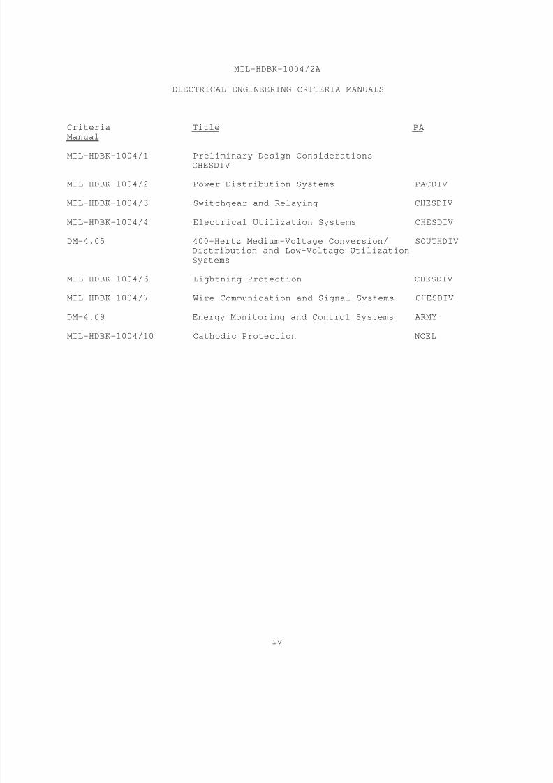
ELECTRICAL ENGINEERING CRITERIA MANUALS
Criteria Title PA
Manual
MIL-HDBK-1004/1 Preliminary Design Considerations
CHESDIV
MIL-HDBK-1004/2 Power Distribution Systems PACDIV
MIL-HDBK-1004/3 Switchgear and Relaying CHESDIV
MIL-HDBK-1004/4 Electrical Utilization Systems CHESDIV
DM-4.05 400-Hertz Medium-Voltage Conversion/ SOUTHDIV
Distribution and Low-Voltage Utilization
Systems
MIL-HDBK-1004/6 Lightning Protection CHESDIV
MIL-HDBK-1004/7 Wire Communication and Signal Systems CHESDIV
DM-4.09 Energy Monitoring and Control Systems ARMY
MIL-HDBK-1004/10 Cathodic Protection NCEL

8/14/2019 UFC 3-550-03N 16 January 2004
http://slidepdf.com/reader/full/ufc-3-550-03n-16-january-2004 12/71
MIL-HDBK-1004/2A
v
POWER DISTRIBUTION SYSTEMS
CONTENTS
Page
Section 1 INTRODUCTION
1.1 Scope........................................... 1
1.2 Cancellation.................................... 11.3 Technical Factors............................... 1
1.3.1 Feeders......................................... 1
1.3.2 Current (Ampere) Levels and Interrupting Duties. 1
1.3.3 Equipment Requirements.......................... 1
1.3.4 Weather Extremes................................ 1
1.3.5 Local Codes..................................... 11.4 Economic Factors................................ 2
1.4.1 Number of Circuits.............................. 2
1.4.2 Voltage......................................... 2
1.4.3 Transformer Losses.............................. 2
1.5 Special Construction............................ 2
1.6 Shore-To-Ship Distribution Systems.............. 31.7 Good Practice................................... 3
Section 2 OVERHEAD DISTRIBUTION SYSTEMS
2.1 Circuit Design.................................. 4
2.1.1 Application..................................... 42.1.2 Capacity........................................ 4
2.1.3 Wire Size....................................... 5
2.1.4 Physical Features............................... 5
2.2 Line Materials.................................. 5
2.2.1 Poles........................................... 5
2.2.1.2 Heights and Classes............................. 52.2.1.3 Strength Requirements........................... 5
2.2.1.4 Safety Factors.................................. 52.2.1.5 Pole Installation............................... 5
2.2.1.6 Configuration................................... 5
2.2.1.7 Crossarms....................................... 52.2.2 Guys and Anchors................................ 6
2.2.2.1 Safety Requirements............................. 6
2.2.2.2 Design of Earth Anchors......................... 6
2.2.3 Conductors...................................... 7
2.2.3.1 Size Limitations................................ 7
2.2.3.2 Normal Primary Lines............................ 72.2.3.3 Tropical and Semitropical Locations............. 7
2.2.3.4 Special Primary Line............................ 8
2.2.3.5 Utilization Lines............................... 8
2.2.3.6 Dissimilar Conductor Connections................ 8
2.2.4 Insulators...................................... 82.2.4.1 Insulator Combinations.......................... 8
2.2.4.2 Dimensions and Loads............................ 8

8/14/2019 UFC 3-550-03N 16 January 2004
http://slidepdf.com/reader/full/ufc-3-550-03n-16-january-2004 13/71
MIL-HDBK-1004/2A
vi
Page
2.2.4.3 Insulation Levels............................... 9
2.2.5 Hardware........................................ 92.3 Line Equipment.................................. 9
2.3.1 Step-Voltage Regulators......................... 9
2.3.2 Capacitors...................................... 10
2.4 Transformers.................................... 102.4.1 Pole Mounting................................... 10
2.4.2 At-Grade Mounting............................... 11
2.4.3 Indoor Installation............................. 11
2.4.4 Overload Capacity............................... 11
2.4.5 Transformer Noise Level......................... 11
2.4.6 Overhead Distribution........................... 112.5 Circuit Interrupting Devices.................... 11
2.5.1 Fuses........................................... 11
2.5.2 Current Limiting Protectors..................... 12
2.5.3 Circuit Breakers................................ 12
2.5.4 Automatic Circuit Reclosers..................... 122.5.5 Nonload-Break Switches.......................... 12
2.5.6 Load-Break Switches............................. 12
2.6 Lightning Protection............................ 12
2.6.1 Requirements.................................... 12
2.6.2 Application..................................... 13
2.7 Clearances...................................... 132.7.1 Contingency Interferences....................... 13
2.7.2 Multipurpose Conditions......................... 13
2.8 Grounding....................................... 13
2.8.1 Safety.......................................... 13
2.8.2 Ground Resistance Path.......................... 13
2.8.3 Maximum Ground Resistance....................... 132.8.4 Grounding Methods............................... 13
2.8.4.1 Ground Rods..................................... 132.8.4.2 Water Pipe Connections.......................... 14
2.8.4.3 Combination of Grounding Methods................ 14
2.8.4.4 Ground Connections.............................. 142.8.5 Overhead Ground Wires........................... 14
2.8.6 Measurement of Ground Resistance................ 14
2.9 Service Drop to Buildings....................... 14
2.10 Right-of-Way.................................... 15
2.10.1 Widths.......................................... 15
2.10.2 Trees........................................... 15
Section 3 UNDERGROUND DISTRIBUTION SYSTEMS
3.1 Circuit Design.................................. 16
3.2 Direct Burial................................... 16
3.2.1 Protection...................................... 16
3.2.2 Installation.................................... 163.2.2.1 Trench Dimensions............................... 16
8/14/2019 UFC 3-550-03N 16 January 2004
http://slidepdf.com/reader/full/ufc-3-550-03n-16-january-2004 14/71
MIL-HDBK-1004/2A
vii
Page
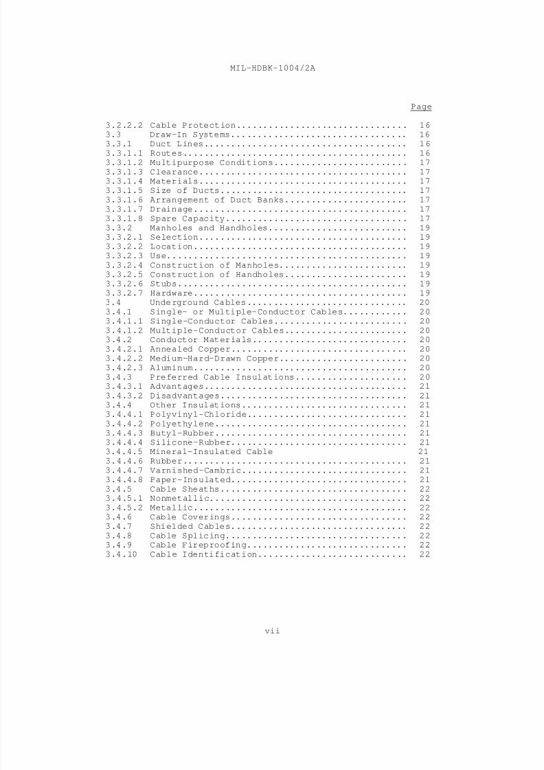
3.2.2.2 Cable Protection................................ 16
3.3 Draw-In Systems................................. 163.3.1 Duct Lines...................................... 16
3.3.1.1 Routes.......................................... 16
3.3.1.2 Multipurpose Conditions......................... 17
3.3.1.3 Clearance....................................... 173.3.1.4 Materials....................................... 17
3.3.1.5 Size of Ducts................................... 17
3.3.1.6 Arrangement of Duct Banks....................... 17
3.3.1.7 Drainage........................................ 17
3.3.1.8 Spare Capacity.................................. 17
3.3.2 Manholes and Handholes.......................... 193.3.2.1 Selection....................................... 19
3.3.2.2 Location........................................ 19
3.3.2.3 Use............................................. 19
3.3.2.4 Construction of Manholes........................ 19
3.3.2.5 Construction of Handholes....................... 193.3.2.6 Stubs........................................... 19
3.3.2.7 Hardware........................................ 19
3.4 Underground Cables.............................. 20
3.4.1 Single- or Multiple-Conductor Cables............ 20
3.4.1.1 Single-Conductor Cables......................... 20
3.4.1.2 Multiple-Conductor Cables....................... 203.4.2 Conductor Materials............................. 20
3.4.2.1 Annealed Copper................................. 20
3.4.2.2 Medium-Hard-Drawn Copper........................ 20
3.4.2.3 Aluminum........................................ 20
3.4.3 Preferred Cable Insulations..................... 203.4.3.1 Advantages...................................... 21
3.4.3.2 Disadvantages................................... 21
3.4.4 Other Insulations............................... 213.4.4.1 Polyvinyl-Chloride.............................. 21
3.4.4.2 Polyethylene.................................... 21
3.4.4.3 Butyl-Rubber.................................... 213.4.4.4 Silicone-Rubber................................. 21
3.4.4.5 Mineral-Insulated Cable 21
3.4.4.6 Rubber.......................................... 21
3.4.4.7 Varnished-Cambric............................... 21
3.4.4.8 Paper-Insulated................................. 21
3.4.5 Cable Sheaths................................... 223.4.5.1 Nonmetallic..................................... 22
3.4.5.2 Metallic........................................ 22
3.4.6 Cable Coverings................................. 22
3.4.7 Shielded Cables................................. 22
3.4.8 Cable Splicing.................................. 223.4.9 Cable Fireproofing.............................. 22
3.4.10 Cable Identification............................ 22

8/14/2019 UFC 3-550-03N 16 January 2004
http://slidepdf.com/reader/full/ufc-3-550-03n-16-january-2004 15/71
MIL-HDBK-1004/2A
viii
Page
3.4.11 Gas Pressurized Cable........................... 23
3.4.11.1Sulfur Hexaflouride Gas......................... 233.4.11.2Installation.................................... 23
3.4.11.3Optional Usage.................................. 23
3.5 Underground Transformers........................ 23
3.5.1 Equipment....................................... 233.5.2 Vault Design.................................... 23
3.6 Cable Ampacity.................................. 24
3.7 Safety Considerations........................... 24
Section 4 SUBMARINE CABLE SYSTEMS
4.1 Preliminary Considerations...................... 254.1.1 Where Permitted................................. 25
4.1.2 Installation Problems........................... 25
4.2 Location Considerations......................... 25
4.2.1 Soundings....................................... 25
4.2.2 Hydraulic Restrictions.......................... 254.2.2.1 Turbulences..................................... 25
4.2.2.2 Current......................................... 25
4.2.2.3 Variable (Changing) Waters...................... 25
4.2.3 Chemical Composition of Waters.................. 25
4.2.4 Marine Traffic.................................. 25
4.3 Installation.................................... 254.3.1 Burying Cable................................... 26
4.3.2 Anchors......................................... 26
4.3.3 Warning Signs................................... 26
4.3.4 Pile Clusters................................... 26
4.3.5 Maps............................................ 26
4.4 Cable Types..................................... 264.4.1 Metallic-Sheathed Cable......................... 26
4.4.2 Armored Cable................................... 264.4.2.1 Application..................................... 27
4.4.2.2 Wire-Armor...................................... 27
4.4.3 Nonmetallic-Sheathed Cable...................... 274.4.4 Shielding....................................... 27
4.5 Electrical Connections.......................... 27
4.5.1 Terminations.................................... 27
4.5.1.1 Potheads........................................ 27
4.5.1.2 Three-Conductor Potheads........................ 27
4.5.2 Splices......................................... 274.5.3 Bonding......................................... 28
Section 5 SUBSTATIONS
5.1 General Considerations.......................... 29
5.1.1.1 Type of System Supplied......................... 30
5.1.1.2 Location........................................ 30
8/14/2019 UFC 3-550-03N 16 January 2004
http://slidepdf.com/reader/full/ufc-3-550-03n-16-january-2004 16/71
MIL-HDBK-1004/2A
ix
Page
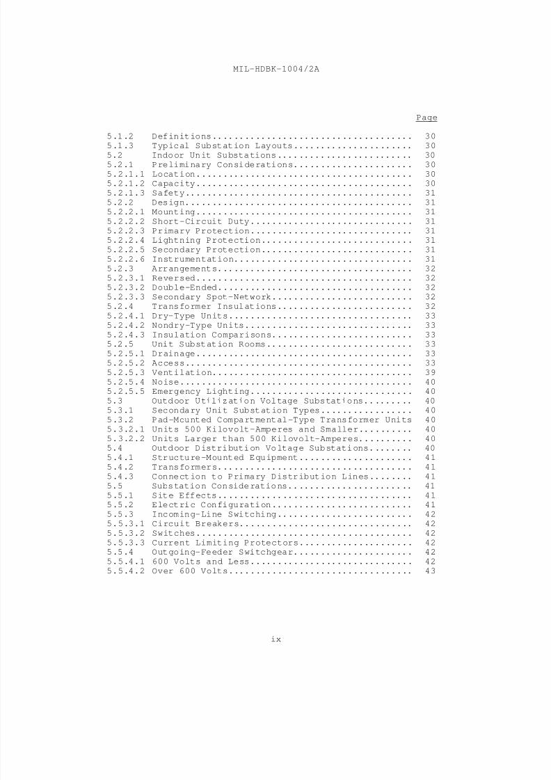
5.1.2 Definitions..................................... 305.1.3 Typical Substation Layouts...................... 30
5.2 Indoor Unit Substations......................... 30
5.2.1 Preliminary Considerations...................... 30
5.2.1.1 Location........................................ 305.2.1.2 Capacity........................................ 30
5.2.1.3 Safety.......................................... 31
5.2.2 Design.......................................... 31
5.2.2.1 Mounting........................................ 31
5.2.2.2 Short-Circuit Duty.............................. 31
5.2.2.3 Primary Protection.............................. 315.2.2.4 Lightning Protection............................ 31
5.2.2.5 Secondary Protection............................ 31
5.2.2.6 Instrumentation................................. 31
5.2.3 Arrangements.................................... 32
5.2.3.1 Reversed........................................ 325.2.3.2 Double-Ended.................................... 32
5.2.3.3 Secondary Spot-Network.......................... 32
5.2.4 Transformer Insulations......................... 32
5.2.4.1 Dry-Type Units.................................. 33
5.2.4.2 Nondry-Type Units............................... 33
5.2.4.3 Insulation Comparisons.......................... 335.2.5 Unit Substation Rooms........................... 33
5.2.5.1 Drainage........................................ 33
5.2.5.2 Access.......................................... 33
5.2.5.3 Ventilation..................................... 39
5.2.5.4 Noise........................................... 405.2.5.5 Emergency Lighting.............................. 40
5.3 Outdoor Utilization Voltage Substations......... 40
5.3.1 Secondary Unit Substation Types................. 405.3.2 Pad-Mounted Compartmental-Type Transformer Units 40
5.3.2.1 Units 500 Kilovolt-Amperes and Smaller.......... 40
5.3.2.2 Units Larger than 500 Kilovolt-Amperes.......... 405.4 Outdoor Distribution Voltage Substations........ 40
5.4.1 Structure-Mounted Equipment..................... 41
5.4.2 Transformers.................................... 41
5.4.3 Connection to Primary Distribution Lines........ 41
5.5 Substation Considerations....................... 41
5.5.1 Site Effects.................................... 415.5.2 Electric Configuration.......................... 41
5.5.3 Incoming-Line Switching......................... 42
5.5.3.1 Circuit Breakers................................ 42
5.5.3.2 Switches........................................ 42
5.5.3.3 Current Limiting Protectors..................... 425.5.4 Outgoing-Feeder Switchgear...................... 42
5.5.4.1 600 Volts and Less.............................. 42
5.5.4.2 Over 600 Volts.................................. 43
8/14/2019 UFC 3-550-03N 16 January 2004
http://slidepdf.com/reader/full/ufc-3-550-03n-16-january-2004 17/71
MIL-HDBK-1004/2A
x
Page
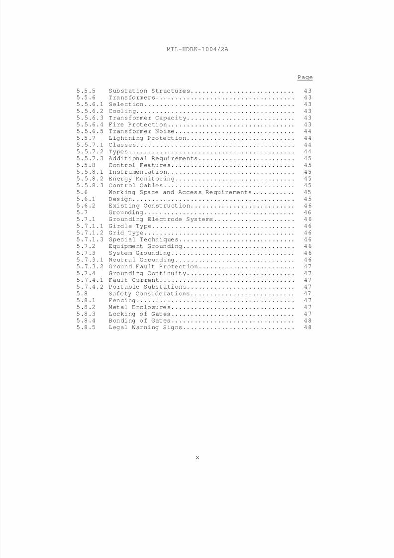
5.5.5 Substation Structures........................... 43
5.5.6 Transformers.................................... 435.5.6.1 Selection....................................... 43
5.5.6.2 Cooling......................................... 43
5.5.6.3 Transformer Capacity............................ 43
5.5.6.4 Fire Protection................................. 435.5.6.5 Transformer Noise............................... 44
5.5.7 Lightning Protection............................ 44
5.5.7.1 Classes......................................... 44
5.5.7.2 Types........................................... 44
5.5.7.3 Additional Requirements......................... 45
5.5.8 Control Features................................ 455.5.8.1 Instrumentation................................. 45
5.5.8.2 Energy Monitoring............................... 45
5.5.8.3 Control Cables.................................. 45
5.6 Working Space and Access Requirements........... 45
5.6.1 Design.......................................... 455.6.2 Existing Construction........................... 46
5.7 Grounding....................................... 46
5.7.1 Grounding Electrode Systems..................... 46
5.7.1.1 Girdle Type..................................... 46
5.7.1.2 Grid Type....................................... 46
5.7.1.3 Special Techniques.............................. 465.7.2 Equipment Grounding............................. 46
5.7.3 System Grounding................................ 46
5.7.3.1 Neutral Grounding............................... 46
5.7.3.2 Ground Fault Protection......................... 47
5.7.4 Grounding Continuity............................ 475.7.4.1 Fault Current................................... 47
5.7.4.2 Portable Substations............................ 47
5.8 Safety Considerations........................... 475.8.1 Fencing......................................... 47
5.8.2 Metal Enclosures................................ 47
5.8.3 Locking of Gates................................ 475.8.4 Bonding of Gates................................ 48
5.8.5 Legal Warning Signs............................. 48

8/14/2019 UFC 3-550-03N 16 January 2004
http://slidepdf.com/reader/full/ufc-3-550-03n-16-january-2004 18/71
MIL-HDBK-1004/2A
xi
Page
FIGURES
1 Duct Line Sections.................................... 18
2 Compartmental-Type Transformer Installation........... 34
3 Radial-Type Articulated Secondary UnitSubstation Installation............................... 35
4 Secondary Unit Substation Grounding................... 36
5 Preferred Design for a Transmission to Distribution
(Primary) Substation................................. 37
6 Secondary-Selective-Type Articulated Secondary Unit
Substation Installation.............................. 38
TABLES
1 Information Required for Circuit Design............... 4
2 Height and Class of Wood Poles........................ 6
3 Wood Pole Sizes for Single Pole Transformer
Installations........................................ 7
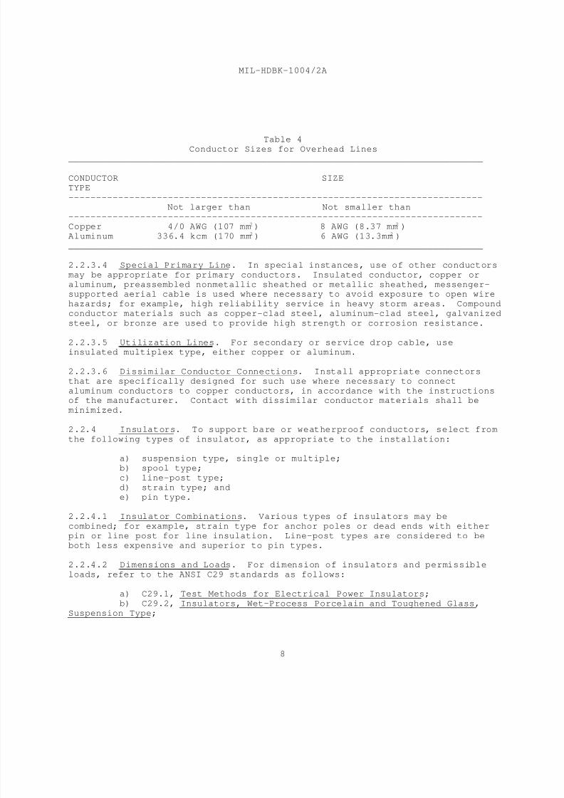
4 Conductor Sizes for Overhead Lines.................... 8
5 Substation Terminology................................ 296 Comparison of Types of Transformer Insulation......... 39
REFERENCES.........................................................49
8/14/2019 UFC 3-550-03N 16 January 2004
http://slidepdf.com/reader/full/ufc-3-550-03n-16-january-2004 19/71
MIL-HDBK-1004/2A
1
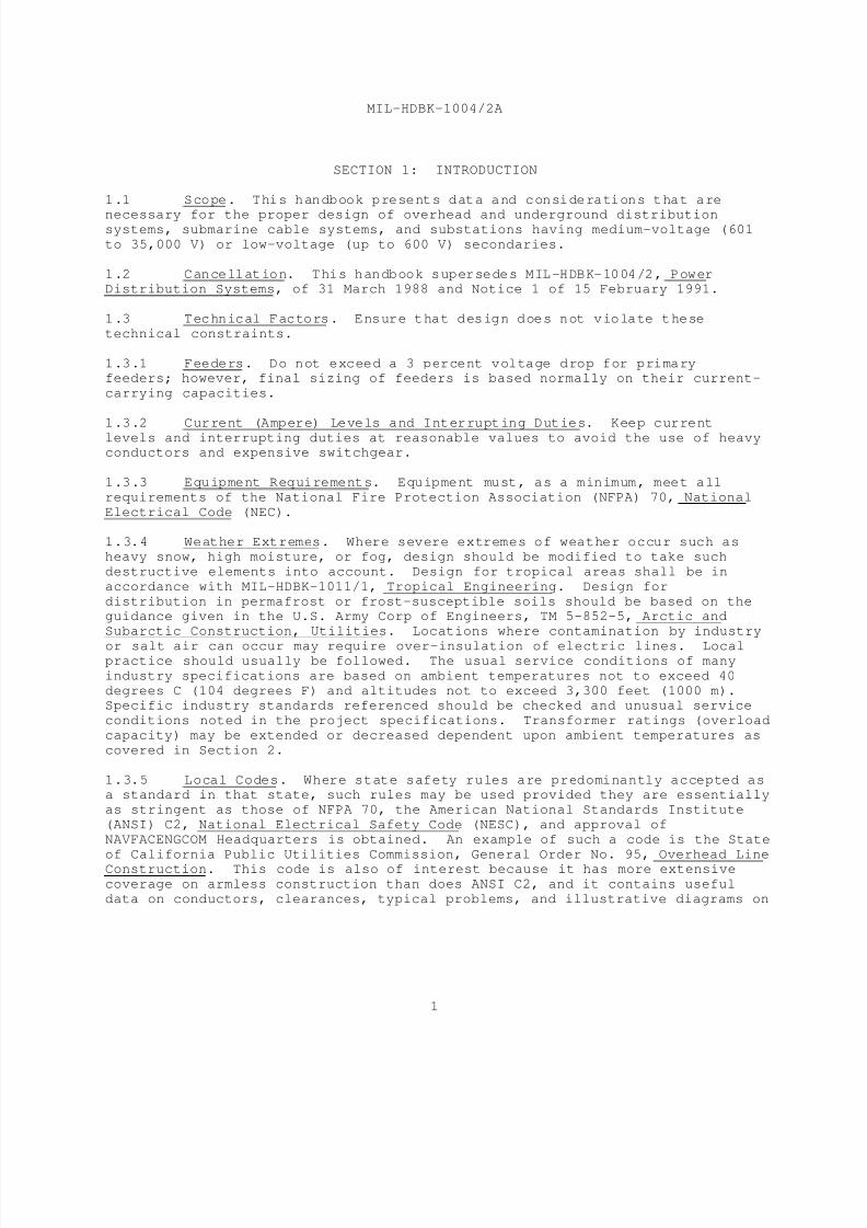
SECTION 1: INTRODUCTION
1.1 Scope. This handbook presents data and considerations that are
necessary for the proper design of overhead and underground distributionsystems, submarine cable systems, and substations having medium-voltage (601
to 35,000 V) or low-voltage (up to 600 V) secondaries.
1.2 Cancellation. This handbook supersedes MIL-HDBK-1004/2, PowerDistribution Systems, of 31 March 1988 and Notice 1 of 15 February 1991.
1.3 Technical Factors. Ensure that design does not violate these
technical constraints.
1.3.1 Feeders. Do not exceed a 3 percent voltage drop for primaryfeeders; however, final sizing of feeders is based normally on their current-
carrying capacities.
1.3.2 Current (Ampere) Levels and Interrupting Duties. Keep current
levels and interrupting duties at reasonable values to avoid the use of heavyconductors and expensive switchgear.
1.3.3 Equipment Requirements. Equipment must, as a minimum, meet all
requirements of the National Fire Protection Association (NFPA) 70, National
Electrical Code (NEC).
1.3.4 Weather Extremes. Where severe extremes of weather occur such as
heavy snow, high moisture, or fog, design should be modified to take such
destructive elements into account. Design for tropical areas shall be in
accordance with MIL-HDBK-1011/1, Tropical Engineering. Design for
distribution in permafrost or frost-susceptible soils should be based on theguidance given in the U.S. Army Corp of Engineers, TM 5-852-5, Arctic and
Subarctic Construction, Utilities. Locations where contamination by industry
or salt air can occur may require over-insulation of electric lines. Localpractice should usually be followed. The usual service conditions of many
industry specifications are based on ambient temperatures not to exceed 40
degrees C (104 degrees F) and altitudes not to exceed 3,300 feet (1000 m).Specific industry standards referenced should be checked and unusual service
conditions noted in the project specifications. Transformer ratings (overload
capacity) may be extended or decreased dependent upon ambient temperatures as
covered in Section 2.
1.3.5 Local Codes. Where state safety rules are predominantly accepted asa standard in that state, such rules may be used provided they are essentially
as stringent as those of NFPA 70, the American National Standards Institute
(ANSI) C2, National Electrical Safety Code (NESC), and approval of
NAVFACENGCOM Headquarters is obtained. An example of such a code is the State
of California Public Utilities Commission, General Order No. 95, Overhead LineConstruction. This code is also of interest because it has more extensive
coverage on armless construction than does ANSI C2, and it contains useful
data on conductors, clearances, typical problems, and illustrative diagrams on

8/14/2019 UFC 3-550-03N 16 January 2004
http://slidepdf.com/reader/full/ufc-3-550-03n-16-january-2004 20/71
MIL-HDBK-1004/2A
2
various rules. The wind and ice loadings are different from those of ANSI C2,
but the clearances illustrated are generally more stringent. Use of these
illustrations will provide a safe and economic installation. The Institute of
Electrical and Electronics Engineers (IEEE) also publishes Clapp, NESC
Handbook which was developed to aid users in understanding and correctly
applying this code.
1.4 Economic Factors. Base the number of circuits and voltage on
economic considerations. Where necessary provide life cycle cost analyses in
accordance with NAVFAC P-442, Economic Analysis Handbook.
1.4.1 Number of Circuits. Keep the number of circuits to a minimum
without compromising reliability, continuity of service, or any of the
technical factors stated previously and thus avoid excessive initial cost.
1.4.2 Voltage. Select a distribution voltage which most economicallyprovides for the magnitude, voltage regulation, and length of feeders (refer
to MIL-HDBK-1004/1, Preliminary Preliminary Design Considerations). Where
groups of large motors are to be served by the distribution system, the most
economical motor voltage is generally the most appropriate distribution
voltage.
1.4.3 Transformer Losses. Most manufacturers offer a variety of designs
where decreased loss design is offset by increased cost. Both no-load (core)
and 100 percent load (coil) losses, plus transformer efficiencies at various
levels are normally available from the manufacturer. In general, a heavily
loaded transformer has lower losses, and therefore has lower life cycle cost,than when it is lightly loaded. Usually, transformers are manufactured with
cores made of silicon-steel materials. More recently developed transformers,
referred to as "the Amorphous Core Transformers," with cores made of amorphous
metal, are also commecially available. In comparison with transformers with
silicon steel cores the amorphous core transformers reduce core losses byapproximately 70%. The initial cost of an amorphous core transformer is about
twice that of a silicon steel core transformer, but the life cycle cost can be
significantely lower as the initial cost decreases as the demand increases. Asimplified approach to evaluating the cost of transformer losses is given in
IEEE 141, Recommended Practice for Electric Power Distribution for Industrial
Plants. A more detailed evaluation of distribution transformer losses isgiven in the Electrical Utility Engineering Reference Book, Distribution
Systems. A method for specifying a transformer based upon minimum losses is
provided in REA 65-2, Evaluation of Large Transformer Losses.
1.5 Special Construction. Refer to MIL-HDBK-1004/4, Electrical
Utilization Systems, for criteria on the design of electrical work installedin earthquake areas. Refer to NAVFAC DM-4.05, 400-Hertz Medium-Voltage
Conversion Distribution and Low-Voltage Utilization Systems, for criteria
applying to 400-Hz, 4,160-V distribution systems. Refer to MIL-HDBK-1012/1,
Electronic Facilities Engineering, for criteria on the design of electronic
facilities. Incoming lines to electronic facilities shall be protectedagainst lightning generated surges in accordance with MIL-HDBK-419, Grounding,
Bonding, and Shielding for Electronics Equipments and Facilities.

8/14/2019 UFC 3-550-03N 16 January 2004
http://slidepdf.com/reader/full/ufc-3-550-03n-16-january-2004 21/71
MIL-HDBK-1004/2A
3
1.6 Shore-To-Ship Distribution Systems. For each facility to be
designed, contact the ultimate user and determine the normal and intermittent
maximum power requirements anticipated; the quality limits for ship service
requirements; and the safety regulations and cold iron needs for ungroundedpower systems in accordance with MIL-HDBK-1025/2, Dockside Utilities for Ship
Service.
1.7 Good Practice. For recognized good practice in electricaldistribution design, refer to the following as appropriate to the requirement:
a) Beeman, Industrial Power Systems Handbook;
b) Fink and Beaty, Standard Handbook for Electrical Engineers,
Reference Book;
c) Electrical Transmission and Distribution Reference Book;
d) Electrical Utility Engineering Reference Book, Distribution
Systems; and
e) Underground Systems Reference Book.
8/14/2019 UFC 3-550-03N 16 January 2004
http://slidepdf.com/reader/full/ufc-3-550-03n-16-january-2004 22/71
MIL-HDBK-1004/2A
4
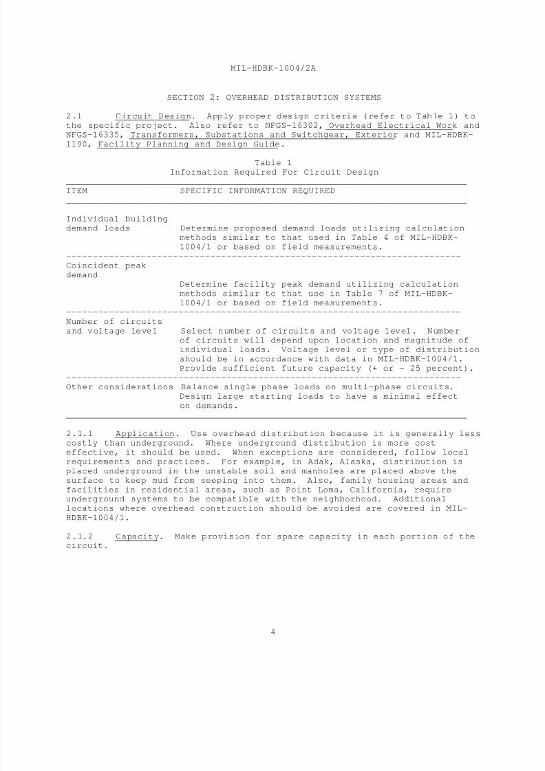
SECTION 2: OVERHEAD DISTRIBUTION SYSTEMS
2.1 Circuit Design. Apply proper design criteria (refer to Table 1) to
the specific project. Also refer to NFGS-16302, Overhead Electrical Work and
NFGS-16335, Transformers, Substations and Switchgear, Exterior and MIL-HDBK-1190, Facility Planning and Design Guide.
Table 1
Information Required For Circuit Design ___________________________________________________________________________
ITEM SPECIFIC INFORMATION REQUIRED
___________________________________________________________________________
Individual building
demand loads Determine proposed demand loads utilizing calculationmethods similar to that used in Table 4 of MIL-HDBK-
1004/1 or based on field measurements.
--------------------------------------------------------------------------
Coincident peak
demandDetermine facility peak demand utilizing calculation
methods similar to that use in Table 7 of MIL-HDBK-
1004/1 or based on field measurements.
--------------------------------------------------------------------------
Number of circuits
and voltage level Select number of circuits and voltage level. Numberof circuits will depend upon location and magnitude of
individual loads. Voltage level or type of distribution
should be in accordance with data in MIL-HDBK-1004/1.
Provide sufficient future capacity (+ or - 25 percent).
--------------------------------------------------------------------------Other considerations Balance single phase loads on multi-phase circuits.
Design large starting loads to have a minimal effect
on demands. ___________________________________________________________________________
2.1.1 Application. Use overhead distribution because it is generally lesscostly than underground. Where underground distribution is more cost
effective, it should be used. When exceptions are considered, follow local
requirements and practices. For example, in Adak, Alaska, distribution is
placed underground in the unstable soil and manholes are placed above the
surface to keep mud from seeping into them. Also, family housing areas and
facilities in residential areas, such as Point Loma, California, requireunderground systems to be compatible with the neighborhood. Additional
locations where overhead construction should be avoided are covered in MIL-
HDBK-1004/1.
2.1.2 Capacity. Make provision for spare capacity in each portion of thecircuit.

8/14/2019 UFC 3-550-03N 16 January 2004
http://slidepdf.com/reader/full/ufc-3-550-03n-16-january-2004 23/71
MIL-HDBK-1004/2A
5
2.1.3 Wire Size. Select wire size in accordance with the current-carrying
capacity required and, where applicable, the voltage-drop limitation.
2.1.4 Physical Features. Select physical design features in accordancewith the type of circuit involved and the type of distribution; that is,
primary or secondary. Select from the following types:
a) Open wire (bare or weatherproof) on insulators.
b) Aerial cable, self-supported or messenger-supported, consisting
of insulated bundled single-conductor cable or multiple-conductor cable.
2.2 Line Materials. Design pole lines based on materials and
construction methods specified in NFGS-16302.
2.2.1 Poles. Wood, concrete (reinforced with prestressing or
pretensioning), or metal (steel or aluminum) may be used. Use concrete or
metal poles only where they are more economical or special considerations
warrant their use. Treat wood poles and crossarms as covered in NFGS-16302.
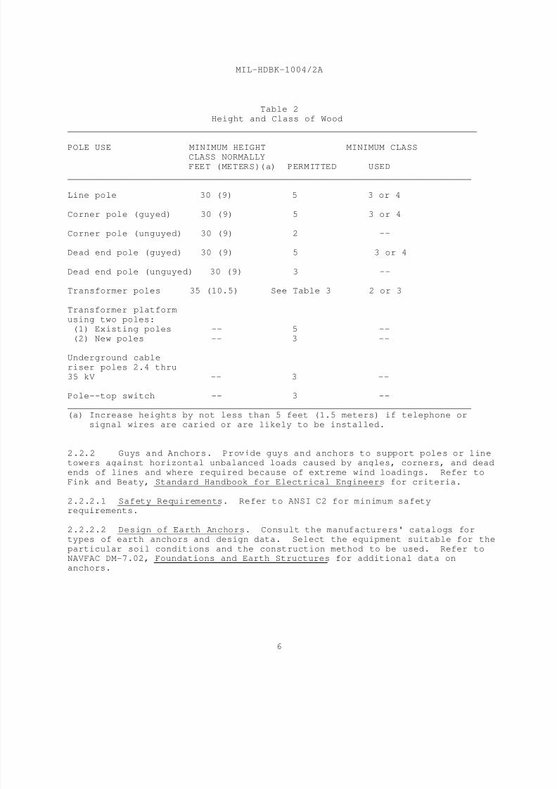
2.2.1.2 Heights and Classes. Limitations on pole heights and classes for
wood poles are given in Table 2. Class normally used refers to primary poles
spaced not more than 200 feet (61 m) apart, which serve industrial or housing
areas and which are generally at least 40 feet (12 m) or more in height. See
ANSI C2 for definition of classes. Refer to Table 3 for data on transformerpoles. Refer to Fink and Beaty, Standard Handbook for Electrical Engineers to
determine the limitations on minimum heights and classes for poles carrying
other equipment.
2.2.1.3 Strength Requirements. Refer to Fink and Beaty, Standard Handbookfor Electrical Engineers and ANSI C2 to determine the adequate physical and
structural requirements.
2.2.1.4 Safety Factors. Refer to ANSI C2 for the minimum safety factors to
be used.
2.2.1.5 Pole Installation. For pole depth, refer to the criteria in Fink
and Beaty, Standard Handbook for Electrical Engineers and ANSI C2. Refer to
Fink and Beaty, Standard Handbook for Electrical Engineers for pole placement
with respect to anchors or braces. Footings or reinforcements of the pole
butt-end shall be as required by foundation conditions.
2.2.1.6 Configuration. Use armless construction for aerial lines because it
is less costly than crossarm construction and its use is aesthetically
preferred. For the same reason, use neutral-supported, secondary cable over
rack-supported individual conductors.
2.2.1.7 Crossarms. Use crossarms mainly for equipment support. Follow the
criteria in Fink and Beaty, Standard Handbook for Electrical Engineers.
8/14/2019 UFC 3-550-03N 16 January 2004
http://slidepdf.com/reader/full/ufc-3-550-03n-16-january-2004 24/71
MIL-HDBK-1004/2A
6
Table 2
Height and Class of Wood
___________________________________________________________________________
POLE USE MINIMUM HEIGHT MINIMUM CLASS
CLASS NORMALLY
FEET (METERS)(a) PERMITTED USED
__________________________________________________________________________
Line pole 30 (9) 5 3 or 4
Corner pole (guyed) 30 (9) 5 3 or 4
Corner pole (unguyed) 30 (9) 2 --
Dead end pole (guyed) 30 (9) 5 3 or 4
Dead end pole (unguyed) 30 (9) 3 --
Transformer poles 35 (10.5) See Table 3 2 or 3
Transformer platform
using two poles:
(1) Existing poles -- 5 --
(2) New poles -- 3 --
Underground cable
riser poles 2.4 thru
35 kV -- 3 --
Pole--top switch -- 3 --
__________________________________________________________________________
(a) Increase heights by not less than 5 feet (1.5 meters) if telephone orsignal wires are caried or are likely to be installed.
2.2.2 Guys and Anchors. Provide guys and anchors to support poles or line
towers against horizontal unbalanced loads caused by angles, corners, and dead
ends of lines and where required because of extreme wind loadings. Refer to
Fink and Beaty, Standard Handbook for Electrical Engineers for criteria.
2.2.2.1 Safety Requirements. Refer to ANSI C2 for minimum safetyrequirements.
2.2.2.2 Design of Earth Anchors. Consult the manufacturers' catalogs for
types of earth anchors and design data. Select the equipment suitable for the
particular soil conditions and the construction method to be used. Refer toNAVFAC DM-7.02, Foundations and Earth Structures for additional data on
anchors.
8/14/2019 UFC 3-550-03N 16 January 2004
http://slidepdf.com/reader/full/ufc-3-550-03n-16-january-2004 25/71
MIL-HDBK-1004/2A
7
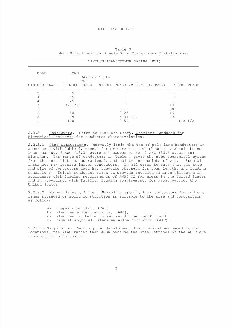
Table 3
Wood Pole Sizes for Single Pole Transformer Installations
___________________________________________________________________________MAXIMUM TRANSFORMER RATING (KVA)
___________________________________________________________________________
POLE ONEBANK OF THREE
ONE
MINIMUM CLASS SINGLE-PHASE SINGLE-PHASE (CLUSTER MOUNTED) THREE-PHASE
--------------------------------------------------------------------------
5 5 -- --
4 15 -- --4 25 -- --
3 37-1/2 -- 15
3 -- 3-15 30
2 50 3-25 45
2 75 3-37-1/2 751 100 3-50 112-1/2
___________________________________________________________________________
2.2.3 Conductors. Refer to Fink and Beaty, Standard Handbook for
Electrical Engineers for conductor characteristics.
2.2.3.1 Size Limitations. Normally limit the use of pole line conductors in
accordance with Table 4, except for primary wires which usually should be not
less than No. 6 AWG (13.3 square mm) copper or No. 2 AWG (33.6 square mm)
aluminum. The range of conductors in Table 4 gives the most economical system
from the installation, operational, and maintenance points of view. Specialinstances may require larger conductors. In all cases be sure that the type
and size of conductors used has adequate strength for span lengths and loading
conditions. Select conductor sizes to provide required minimum strengths inaccordance with loading requirements of ANSI C2 for areas in the United States
and in accordance with facility loading requirements for areas outside the
United States.
2.2.3.2 Normal Primary Lines. Normally, specify bare conductors for primary
lines stranded or solid construction as suitable to the size and composition
as follows:
a) copper conductor, (Cu);b) aluminum-alloy conductor, (AAC);
c) aluminum conductor, steel reinforced (ACSR); and
d) high-strength all-aluminum alloy conductor (AAAC).
2.2.3.3 Tropical and Semitropical Locations. For tropical and semitropicallocations, use AAAC rather than ACSR because the steel strands of the ACSR are
susceptible to corrosion.
8/14/2019 UFC 3-550-03N 16 January 2004
http://slidepdf.com/reader/full/ufc-3-550-03n-16-january-2004 26/71
MIL-HDBK-1004/2A
8
Table 4Conductor Sizes for Overhead Lines
___________________________________________________________________________
CONDUCTOR SIZETYPE
---------------------------------------------------------------------------
Not larger than Not smaller than
---------------------------------------------------------------------------
Copper 4/0 AWG (107 mm ) 8 AWG (8.37 mm )2 2
Aluminum 336.4 kcm (170 mm ) 6 AWG (13.3mm )2 2
___________________________________________________________________________
2.2.3.4 Special Primary Line. In special instances, use of other conductors
may be appropriate for primary conductors. Insulated conductor, copper or
aluminum, preassembled nonmetallic sheathed or metallic sheathed, messenger-supported aerial cable is used where necessary to avoid exposure to open wire
hazards; for example, high reliability service in heavy storm areas. Compound
conductor materials such as copper-clad steel, aluminum-clad steel, galvanized
steel, or bronze are used to provide high strength or corrosion resistance.
2.2.3.5 Utilization Lines. For secondary or service drop cable, useinsulated multiplex type, either copper or aluminum.
2.2.3.6 Dissimilar Conductor Connections. Install appropriate connectors
that are specifically designed for such use where necessary to connect
aluminum conductors to copper conductors, in accordance with the instructionsof the manufacturer. Contact with dissimilar conductor materials shall be
minimized.
2.2.4 Insulators. To support bare or weatherproof conductors, select from
the following types of insulator, as appropriate to the installation:
a) suspension type, single or multiple;
b) spool type;
c) line-post type;
d) strain type; and
e) pin type.
2.2.4.1 Insulator Combinations. Various types of insulators may be
combined; for example, strain type for anchor poles or dead ends with either
pin or line post for line insulation. Line-post types are considered to be
both less expensive and superior to pin types.
2.2.4.2 Dimensions and Loads. For dimension of insulators and permissible
loads, refer to the ANSI C29 standards as follows:
a) C29.1, Test Methods for Electrical Power Insulators;
b) C29.2, Insulators, Wet-Process Porcelain and Toughened Glass,
Suspension Type;

8/14/2019 UFC 3-550-03N 16 January 2004
http://slidepdf.com/reader/full/ufc-3-550-03n-16-january-2004 27/71
MIL-HDBK-1004/2A
9
c) C29.3, Wet-Process Porcelain Insulators, Spool Type;
d) C29.4, Wet-Process Porcelain Insulators, Strain Type;
e) C29.5, Wet-Process Porcelain Insulators, Low- and Medium-Voltage
Types;
f) C29.6, Wet-Process Porcelain Insulators, High-Voltage Pin Type;g) C29.7, Wet-Process Porcelain Insulators, High-Voltage Line-Post
Type;
h) C29.8, Wet-Process Porcelain Insulators, Apparatus Cap and Pin
Type; andi) C29.9, Wet-Process Porcelain Insulators, Apparatus Post-Type.
In addition to the above, refer to the National Electrical Manufacturers
Association NEMA HV-2, Application Guide for Ceramic Suspension Insulators.
Also, refer to Fink and Beaty, Standard Handbook for Electrical Engineers.
2.2.4.3 Insulation Levels. The application of ANSI C2 requires higher
insulation levels in locations where severe lightning, high atmospheric
contamination, or other unfavorable conditions exist. This applies
particularly to areas where saltspray contamination can cause increased
operating stresses. Local practice in such areas should be checked indetermining how much increased insulation is considered necessary for
insulators and whether increased leakage distances for bushings and cable
terminations is also desirable.
2.2.5 Hardware. In locations sensitive to electromagnetic interference,
install lines underground. If aerial lines are provided, insulators must beof the radio-freed type. Provide hardware components with locknuts to avoid
loose connections, which could cause static. Locknuts must be threaded, and
of a type which will prevent loosening of the connection when wood members
shrink.
2.3 Line Regulation. The voltage drop for primary lines shall not
exceed 3 percent. Maintain the power factor of the line as close to unity as
economically practical so as to minimize system losses. Regulation utilizingload-tap-changing transformers to correct line voltage variations resulting
from changing loads or utility company sending-end voltage swings is covered
in Section 5. Requirements for line equipment follow:
2.3.1 Step-Voltage Regulators. Step-voltage regulators can rarely be
justified economically for new construction. They may be used on existing
construction to meet voltage drop criteria when proven to be more cost
effective than controlling the voltage drop by use of larger conductors,
provision of additional lines, or by the installation of capacitors. Refer toFink and Beaty, Standard Handbook for Electrical Engineers for methods of
sizing feeder voltage regulators and for regulator safety and line drop
compensation setting requirements. Single-phase regulators are preferable as
being less costly but require more installation space.

8/14/2019 UFC 3-550-03N 16 January 2004
http://slidepdf.com/reader/full/ufc-3-550-03n-16-january-2004 28/71
MIL-HDBK-1004/2A
10
2.3.2 Capacitors. Capacitors raise voltage levels by reducing the
reactive line losses associated with reactive current flow between the
capacitor installation and the power supply. It is rarely economical to apply
them for voltage improvement only. Capacitors are justified when their cost
over their service life is less than any utility company low-power-factorpenalty cost. Take into account the cost of switching equipment to meet any
functional or utility company prohibitions against a leading power factor.
Base design on shunt power capacitors that conform to IEEE 18, Shunt Power
Capacitors. Take into account the following considerations:
a) Fixed capacitance is the amount of capacitance that can be
applied continuously without excessive voltage rise at reduced load.
b) Switched capacitance is an additional amount of capacitance that
can be applied, if provision is made to switch off this additional amount whendemand is reduced.
c) Select the type of capacitor switching that is best for the
condition at hand. Possible choices include remote control of the capacitor
switching device, time clock control, or power factor or voltage sensitiverelay control.
d) Install capacitors in banks on poles, at-grade, or in a substa-
tion, as near as possible to the centroid of the area where correction is
required.
2.4 Transformers. Transformers can be mounted on poles, at-grade, or
indoors depending upon size and site requirements. Select a standardized
three-phase transformer, except where the load is small enough to justify a
single-phase transformer. Use oil-insulated transformers, except where site
conditions or economic considerations make their use prohibitive. Considerloading, noise level, and transformer protection requirements. Do not use
askarel-insulated and nonflammable, fluid-insulated transformers because of
environmental concerns as to their insulation liquid. Use of other types ofinsulation must be economically or functionally justified. Less-flammable,
liquid-insulated units may be necessary where oil-insulated transformers
cannot meet fire-exposure requirements as listed in MIL-HDBK-1008, FireProtection for Facilities Engineering, Design, and Construction. Epoxy-
encased ventilated dry-type units may be appropriate in areas where liquid-
insulation loss might result in water pollution.
2.4.1 Pole Mounting. For single-pole mounting, limit the size of single-
phase or three-phase units in accordance with Table 3. Do not use pole-platform mounting (two-pole structures) except in instances where other
methods are not satisfactory. It is recommended that maximum transformer size
be limited to the sizes shown in Table 3. For installations of 225 to 500
kVA, pad-mounted, compartmental-type transformers are recommended.
8/14/2019 UFC 3-550-03N 16 January 2004
http://slidepdf.com/reader/full/ufc-3-550-03n-16-january-2004 29/71
MIL-HDBK-1004/2A
11
2.4.2 At-Grade Mounting. For at-grade mounting on a concrete base, there
is no kVA limit. Tamper-resistant transformers (classified as pad-mounted
compartmental-type units) should generally not be specified in ratings of over
500 kVA, but in no case larger than 750 kVA. When sheet-metal enclosures arenot tamper-resistant, provide ground-mounted units with a fenced enclosure or
even a concrete or brick structure, where adverse weather conditions make such
an installation advisable. For required clearances between buildings and
insulated transformers, refer to MIL-HDBK-1008.
2.4.3 Indoor Installations. Indoor installations are covered in Section
5.
2.4.4 Overload Capacity. Consider the accelerated loss of equipment life
if transformers are to be overloaded. Refer to ANSI C57.91 Guide for LoadingMineral-Oil-Overhead and Pad-Mounted Distribution Transformers Rated 500 kVA
and Less with 65 Degrees C or 55 Degrees C Average Winding, C57.92 Guide for
Loading Mineral-Oil-Immersed Power Transformers up to and Including 100 MVA
with 55 Degree C or 65 Degree C Winding Rise, and C57.96 Guide for Loading
Dry-Type Distribution and Power Transformers and Fink and Beaty, StandardHandbook for Electrical Engineers.
2.4.5 Transformer Noise Level. Refer to NEMA TR-1, Transformers,
Regulators and Reactors for maximum permissible noise levels for transformers.
2.4.6 Overhead Distribution. Use the criteria in ANSI C57.12.20,Requirements for Overhead Type Distribution Transformers, 500 kVA and Smaller:
High-Voltage 67,000 Volts and Below; Low-Voltage 15,000 Volts and Below. Do
not use self-protected transformers having an internal secondary breaker,
internal primary fusing, and integrally mounted surge arresters. These
transformer accessories are provided for transformers generally described byindustry as a pole-mounted type. The replacement of fuse links is considered
to require specialized personnel not usually available at naval facilities.
2.5 Circuit Interrupting Devices. Select from fuses, circuit breakers,
and automatic circuit reclosers for protective line considerations. Provide
switches to localize defective portions of aerial and underground circuits andto accomplish dead-circuit work. Select from nonload-break or load-break type
switches.
2.5.1 Fuses. After consideration of the necessary current-carrying
capacities, interrupting duties, and time-current melting and clearing
characteristics, select fuses from the following types:
a) open fusible link,
b) expulsion type,
c) boric-acid type, and
d) current-limiting type.
8/14/2019 UFC 3-550-03N 16 January 2004
http://slidepdf.com/reader/full/ufc-3-550-03n-16-january-2004 30/71
MIL-HDBK-1004/2A
12
2.5.2 Current Limiting Protectors. These fusible type devices developed
under an Electric Power Research Institute (EPRI) project, provide current
limiting on up to 15.5-kV systems for up to 1,200 A continuous currents. Use
them only where higher continuous ratings are required than are available fromstandard fused cutouts or power fuse disconnecting units.
2.5.3 Circuit Breakers. Use a circuit breaker rating adequate for the
load interrupting duty and which provides selectivity with circuit breakersand fuses ahead of or after the circuit breaker.
2.5.4 Automatic Circuit Reclosers. Use the criteria in NEMA SG-13,
Automatic Circuit Reclosers, Automatic Line Sectionalizers and Oil-Filled
Capacitor Switches for Alternating Current Systems. Use of automaticreclosing for other than overhead lines serving residential or commercial
loads may cause problems. In selecting the type of automatic circuit
recloser, consider the reliability and continuity of service. Reclosers may
consist of a circuit breaker or a multiple switching device. Reclosers
operate so that a faulted circuit may be opened and then, eitherinstantaneously or with deliberate time delay, reclosed. Up to three
reclosures with varying time intervals may be used. Coordinate automatic
circuit reclosers with fuses or circuit breakers on the same circuit.
2.5.5 Nonload-Break Switches. Use nonload-break switches only for the
interruption of circuits that carry no appreciable load. Select the typeapplicable, depending on circuit importance, load, voltage, and fault circuit
duty. The types available are porcelain disconnect fuse cutouts, plain or
fused single-pole air disconnect switches, and disconnect fuse cutouts of
various types. Refer to manufacturers' catalogs and NEMA SG-2, High-Voltage
Fuses. Disconnecting and horn gap switches covered by ANSI C37.30, Definitionsand Requirements for High-Voltage Air Switches, Insulators, and Bus Supports
and ANSI C37.32, Schedules of Preferred Ratings, Manufacturing Specifications,
and Application Guide for High-Voltage Air Switches, Bus Supports, and SwitchAccessories are also nonload-break switches.
2.5.6 Load-Break Switches Load-break switches are provided with aninterrupting device capable of disconnecting circuits under load. Fuse
cutouts, (covered by NEMA SG-2) which are designed to be load-break are
available, as are load interrupter switches which conform to ANSI C37.30 and
C37.32. Vacuum switches provide load-break features. Vacuum switches can
provide a wide variety of operators and should be considered as an economical
method of providing automatic or remotely controlled switching.
2.6 Lightning Protection
2.6.1 Requirements. Lightning protection can be provided by installing
surge (lightning) arresters, open or expulsion gaps, or overhead ground wires,or by all three methods combined. Also, consider the weather. For most
distribution circuits, distribution surge arresters protecting transformers
and aerial-to-underground transitions are adequate. Overhead ground wires are
rarely considered to be an economical installation for distribution lines, but
8/14/2019 UFC 3-550-03N 16 January 2004
http://slidepdf.com/reader/full/ufc-3-550-03n-16-january-2004 31/71
MIL-HDBK-1004/2A
13
are often used for protection of transmission lines. In areas where annual
lightning storms are few, no protection for lightning-induced surges may be
necessary. Local naval facility or utility company practice should generally
be followed (refer to MIL-HDBK-1004/6, Lightning Protection) for equipment
protection, aerial-to-underground transition points, and other appropriate
locations.
2.6.2 Application. Select the proper arrester in accordance with the
Basic Impulse Insulation Level (BIL) that applies to the voltage level of the
circuit. Follow the criteria in ANSI C62.1, Surge Arrestors for AC PowerCircuits; ANSI C62.2, Guide for Application of Valve-Type Surge Arresters for
Alternating Current Systems and ANSI C62.33, Varistor Surge-Protective
Devices.
2.7 Clearances. Provide the necessary horizontal and vertical
clearances from adjacent physical objects, such as buildings, structures, orother electric lines, as required by ANSI C2.
2.7.1 Contingency Interferences. Make provision to protect against
contingency interferences, such as broken poles, broken crossarms, or broken
circuit conductors.
2.7.2 Multipurpose Conditions. Provide for clearance conditions arising
from multipurpose joint use of poles.
2.8 Grounding. For information on grounding of overhead distribution
systems, refer to ANSI C2.
2.8.1 Safety. Provide grounding for all equipment and structures
associated with electrical systems to prevent shock from static or dynamic
voltages.
2.8.2 Ground Resistance Path. Provide a low impedance path at the source
of fault currents, if a circuit contains a deliberate ground connection.
2.8.3 Maximum Ground Resistance. Do not exceed maximum ground resistance
values specified in NFGS-16301, Underground Electrical Work and NFGS-16302,
and ANSI C2. Consider the source of electric power, capacity, magnitude offault current, and method of system grounding, as they affect this resistance.
2.8.4 Grounding Methods. Grounding provisions shall conform to NFPA 70.
Grounding methods for transformers mounted at grade are covered in Section 5.
2.8.4.1 Ground Rods. Ground rods may be used either singly or in clusters.Drive the ground rods to ground water level for an effective and permanent
installation. Provide for corrosion prevention by a proper choice of metals
or by cathodic protection. Where ground water cannot be reached, chemicals
such as magnesium sulphate (MgSO ) or copper sulphate (CuSO ) may be used to4 4
improve soil conductivity where necessary. Manufacturers of ground rods can

8/14/2019 UFC 3-550-03N 16 January 2004
http://slidepdf.com/reader/full/ufc-3-550-03n-16-january-2004 32/71
MIL-HDBK-1004/2A
14
provide data on such treatment. Provide for easy maintenance and periodic
testing. Driving ground rods deeper using sectional rods may be more
effective than using multiple rods. In many cases, soil variations and
possible bedrock may make provision of additional rods less expensive.
2.8.4.2 Water Pipe Connections. Make no connection to any sprinkler pipingin accordance with NFPA 24, Installation of Private Fire Service Mains and
their Appurtenances. The electrical system may be grounded to a water supply
system except where nonmetallic pipes, cathodically protected metallic pipes,
or insulating couplings are incorporated in the water pipe system. Supplementthe water pipe connection by other grounding electrodes where required by NFPA
70.
2.8.4.3 Combination of Grounding Methods. Where the ground resistance in an
existing system is high, any of the aforementioned methods may be combined to
effect improvement.
2.8.4.4 Ground Connections. Keep wires running from protective devices (for
example, gaps, grading rings, expulsion or protection tubes, and surge
arresters) to ground as straight and short as possible. Where bends are
necessary, provide them of large radii to keep the surge impedance as low aspossible.
2.8.5 Overhead Ground Wires. Where overhead ground wires are used for
protection of electric lines, provide a ground connection from the overhead
ground wire to a wire loop or a ground plate at the base of the pole or to a
driven rod, depending on the existing soil conditions. Use of wire wraps orpole butt plates is allowed by ANSI C2 only in areas of very low soil
resistivity. Ground the overhead ground wire at each pole.
2.8.6 Measurement of Ground Resistance. Measure ground resistance by
using one of the following methods:
a) Three-Electrode Method. In the three-electrode method, two test
electrodes shall be used to measure resistance of the third electrode, theground point. A self-contained source of alternating current and a battery-
operated vibrator source providing direct reading are commercially available.
b) Fall-of-Potential Method. The fall-of-potential method involves
an ungrounded alternating current power source which circulates a measured
current to ground. Voltage readings taken of the connection to auxiliary
grounds allow use of Ohm's law to determine the ground resistance. Refer to
Fink and Beaty, Standard Handbook for Electrical Engineers.
2.9 Service Drop to Buildings. Local considerations and current
capacities dictate the type of service drop to buildings from overhead
distribution systems. Provide either underground service into the building
from a pole riser or self-supporting service cable strung from the pole to the
building (refer to ANSI C2).
8/14/2019 UFC 3-550-03N 16 January 2004
http://slidepdf.com/reader/full/ufc-3-550-03n-16-january-2004 33/71
MIL-HDBK-1004/2A
15
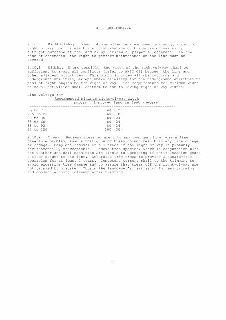
2.10 Right-of-Way. When not installed on government property, obtain a
right-of-way for the electrical distribution or transmission system by
outright purchase of the land or by limited or perpetual easement. In the
case of easements, the right to perform maintenance on the line must becovered.
2.10.1 Widths. Where possible, the width of the right-of-way shall be
sufficient to avoid all conflicts (refer to ANSI C2) between the line andother adjacent structures. This width includes all obstructions and
underground utilities, except where necessary for the underground utilities to
pass at right angles to the right-of-way. The requirements for minimum width
on naval activities shall conform to the following right-of-way widths:
Line voltage (kV)Recommended minimum right-of-way width
across unimproved land in feet (meters)
------------------------------------------------------------------
Up to 7.5 40 (12)
7.5 to 20 60 (18)20 to 35 80 (24)
35 to 68 80 (24)
68 to 92 80 (24)
92 to 120 100 (30)
2.10.2 Trees. Because trees adjacent to any overhead line pose a lineclearance problem, ensure that growing trees do not result in any line outage
or damage. Complete removal of all trees in the right-of-way is probably
environmentally unacceptable. Remove tree species, which in conjunction with
the weather and soil condition are liable to uprooting if their location poses
a clear danger to the line. Otherwise trim trees to provide a hazard-freeoperation for at least 2 years. Competent persons shall do the trimming to
avoid excessive tree damage and to assure that trees off the right-of-way are
not trimmed by mistake. Obtain the landowner's permission for any trimmingand conduct a though cleanup after trimming.

8/14/2019 UFC 3-550-03N 16 January 2004
http://slidepdf.com/reader/full/ufc-3-550-03n-16-january-2004 34/71
MIL-HDBK-1004/2A
16
Section 3: UNDERGROUND DISTRIBUTION SYSTEMS
3.1 Circuit Design. Follow the circuit design procedure outlined in
Section 2 of this handbook for overhead distribution systems. For additional
criteria, refer to MIL-HDBK-1190.
3.2 Direct Burial. Install direct-burial cables only in areas that are
rarely disturbed. After first considering economic, maintenance, and
reliability effects, restrict direct burial to light loads, to roadway
lighting systems, and to long untapped runs in low density areas. In some
instances, a minimal amount of taps may be acceptable.
3.2.1 Protection. For protection against mechanical injury, medium-
voltage direct-burial cables can be provided with a protective covering of
metal armor. Consider the need for such protection, such as against dig-ins
or because of possible termite or rodent attack, on a case-by-case basis.
Possibly other protective means are more economical. Where corrosionconsiderations are of importance, provide armored cables with a plastic or
synthetic rubber jacket. For cable specifications, refer to NFGS-16301.
Provide a colored warning tape 6 inches (52.4 mm) above the direct-burial
cable.
3.2.2 Installation
3.2.2.1 Trench Dimensions. Provide trenches in accordance with the
requirements of NFGS-16301 and NFGS-02225 Excavation, Backfilling, and
Compacting for Utilities.
3.2.2.2 Cable Protection. General installations shall be in accordance with
requirements of NFGS-16301. Where additional protection of buried cable
against dig-ins is necessary, provide a continuous 1-inch (25.4 mm) thicktreated wood plank or a concrete slab, not less than 2 inches (50.8 mm) thick,
located directly above a top layer of sand in lieu of or in addition to a
protective covering. Accommodate protection against termites or rodents byusing a chemical treatment. Obtain approval of the treatment by the facility
prior to use.
3.3 Draw-In Systems. Draw-in systems consist of duct systems (which may
include access points such as manholes and handholes) in which cable is drawn
after the duct system has been installed. Provide a draw-in system whereoverhead distribution is not feasible (refer to MIL-HDBK-1004/1). Provide a
draw-in system for distribution of large blocks of electric power, where many
circuits follow the same route or are run under permanent hard pavements, or
where service reliability is paramount.
3.3.1 Duct Lines
3.3.1.1 Routes. Select duct line routes to balance maximum flexibility with
minimum cost and to avoid foundations for future buildings and other
structures.

8/14/2019 UFC 3-550-03N 16 January 2004
http://slidepdf.com/reader/full/ufc-3-550-03n-16-january-2004 35/71
MIL-HDBK-1004/2A
17
3.3.1.2 Multipurpose Conditions. Where it may be necessary to run
communication lines along with electric power distribution lines, provide two
isolated systems in separate manhole compartments. Where possible, run ducts
in the same concrete envelope.
3.3.1.3 Clearance. Keep electric and communication ducts clear of all other
underground utilities, especially high-temperature water or steam pipes.
3.3.1.4 Materials. Acceptable standard materials include the various typesof plastic as specified in NFGS-16301. Rigid steel conduit may also be
installed below grade and provided with field or factory applied coatings for
corrosion protection where required.
3.3.1.5 Size of Ducts. Base the size of conduits in a duct bank shall be
based on consideration of the following factors:
a) for general electric power distribution, do not use less than 5
inch (127 mm) ducts;
b) for communication duct banks, normally use 4 in. (101.6 mm)ducts although 3 inch (76.2 mm) ducts may be acceptable in some cases;
c) special cases may require use of larger sizes, but such sizes
shall be functionally justified.
3.3.1.6 Arrangement of Duct Banks. For best heat dissipation, use anarrangement of two conduits wide or high. This may be impossible where a
large number of ducts are involved. The vertical, two-conduit-wide
arrangement enables the cables to be more easily racked on manhole walls but
may not be as economical as the horizontal two-conduit-high arrangement. For
dimensions and arrangement of duct banks see Figure 1. Encase conduits inconcrete in accordance with NFGS-16301.
3.3.1.7 Drainage. Drain all ducts to manholes with a constant slope inaccordance with NFGS-16301. Where two manholes are at different elevations, a
single slope following the general slope of the terrain may be the most
economical. Where grades are flat or crest between manholes, a single slopeusually requires too much depth in one of the manholes. In this event,
generally slope the duct from the crest area to both manholes, keeping a
minimum earth coverage on the highest elevation.
3.3.1.8 Spare Capacity. Include ducts for planned future expansion, plus 25
percent additional spare ducts for unplanned expansion.

8/14/2019 UFC 3-550-03N 16 January 2004
http://slidepdf.com/reader/full/ufc-3-550-03n-16-january-2004 36/71
MI L - HDBK - 1 0 0 4 / 2 A
1 8
8/14/2019 UFC 3-550-03N 16 January 2004
http://slidepdf.com/reader/full/ufc-3-550-03n-16-january-2004 37/71
MIL-HDBK-1004/2A
19
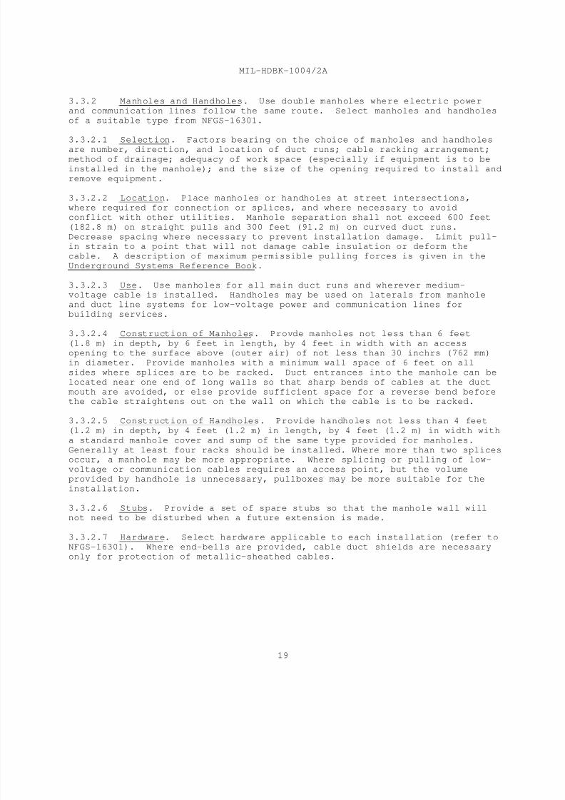
3.3.2 Manholes and Handholes. Use double manholes where electric power
and communication lines follow the same route. Select manholes and handholes
of a suitable type from NFGS-16301.
3.3.2.1 Selection. Factors bearing on the choice of manholes and handholesare number, direction, and location of duct runs; cable racking arrangement;
method of drainage; adequacy of work space (especially if equipment is to be
installed in the manhole); and the size of the opening required to install and
remove equipment.
3.3.2.2 Location. Place manholes or handholes at street intersections,
where required for connection or splices, and where necessary to avoid
conflict with other utilities. Manhole separation shall not exceed 600 feet
(182.8 m) on straight pulls and 300 feet (91.2 m) on curved duct runs.
Decrease spacing where necessary to prevent installation damage. Limit pull-in strain to a point that will not damage cable insulation or deform the
cable. A description of maximum permissible pulling forces is given in the
Underground Systems Reference Book.
3.3.2.3 Use. Use manholes for all main duct runs and wherever medium-voltage cable is installed. Handholes may be used on laterals from manhole
and duct line systems for low-voltage power and communication lines for
building services.
3.3.2.4 Construction of Manholes. Provde manholes not less than 6 feet
(1.8 m) in depth, by 6 feet in length, by 4 feet in width with an accessopening to the surface above (outer air) of not less than 30 inchrs (762 mm)
in diameter. Provide manholes with a minimum wall space of 6 feet on all
sides where splices are to be racked. Duct entrances into the manhole can be
located near one end of long walls so that sharp bends of cables at the duct
mouth are avoided, or else provide sufficient space for a reverse bend beforethe cable straightens out on the wall on which the cable is to be racked.
3.3.2.5 Construction of Handholes. Provide handholes not less than 4 feet(1.2 m) in depth, by 4 feet (1.2 m) in length, by 4 feet (1.2 m) in width with
a standard manhole cover and sump of the same type provided for manholes.
Generally at least four racks should be installed. Where more than two splicesoccur, a manhole may be more appropriate. Where splicing or pulling of low-
voltage or communication cables requires an access point, but the volume
provided by handhole is unnecessary, pullboxes may be more suitable for the
installation.
3.3.2.6 Stubs. Provide a set of spare stubs so that the manhole wall willnot need to be disturbed when a future extension is made.
3.3.2.7 Hardware. Select hardware applicable to each installation (refer to
NFGS-16301). Where end-bells are provided, cable duct shields are necessary
only for protection of metallic-sheathed cables.

8/14/2019 UFC 3-550-03N 16 January 2004
http://slidepdf.com/reader/full/ufc-3-550-03n-16-january-2004 38/71
MIL-HDBK-1004/2A
20
3.4 Underground Cables. Cable installations make up a large portion of
the initial distribution system investment, contribute to a lesser extent to
the annual maintenance and operating costs, and affect system reliability.Therefore, underground cables and their accompanying protective and operating
devices should be selected in accordance with criteria set forth in the
following paragraphs. The joint specifications of the Insulated Cable
Engineers Association-National Electrical Manufacturers Association (ICEA-NEMA) and the specifications of the Association of Edison Illuminating
Companies (AEIC) should be used as covered by NFGS-16301. ICEA-NEMA
specifications cover medium-voltage cables which are manufactured as stock
items. Requiring medium-voltage cable to meet AEIC specifications should be
limited to medium-voltage cables which are not stock items (35-kV rating) or
where the footage installed is large enough for manufacturers to make aspecial run.
3.4.1 Single- or Multiple-Conductor Cables
3.4.1.1 Single-Conductor Cables. Single-conductor cables are usually usedin distribution systems because the installed cost is less than that of
multiple-conductor cables.
3.4.1.2 Multiple-Conductor Cables. Select multiple-conductor cables where
justified by special considerations such as installation in cable trays,
twisted to provide lower inductance for 400-Hz distribution systems, or forHigh-altitude Electromagnetic Pulse (HEMP) hardened systems.
3.4.2 Conductor Materials
3.4.2.1 Annealed Copper. Select annealed copper for high conductivity,flexibility, and ease of handling; it is used in all forms of insulated
conductors.
3.4.2.2 Medium-Hard-Drawn Copper. Medium-hard-drawn copper has greater
tensile strength than annealed copper but may not be available as a stock
item. Its use in long pulls and unsupported vertical risers is acceptable;however, procurement difficulties make other designs more advisable.
3.4.2.3 Aluminum. Generally, aluminum conductors are permitted as a
contractor's option to copper subject to the restrictions of NFGS-16301,
except where corrosive conditions limit usage.
3.4.3 Preferred Cable Insulations. Insulation material to be used in a
specific design depends on the system voltage and the thermal, mechanical, and
chemical effects from the installation involved. Use crosslinked-Polyethylene
(XLP) or ethylene-propylene rubber (EPR) whenever possible. These insulations
provide the maximum rated conductor temperatures for operating, overload, andshort-circuit conditions for cables rated up to a maximum of 35 kV.
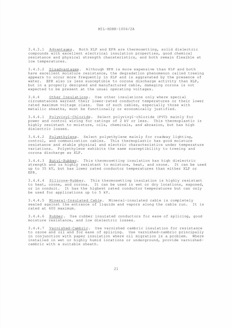
8/14/2019 UFC 3-550-03N 16 January 2004
http://slidepdf.com/reader/full/ufc-3-550-03n-16-january-2004 39/71
MIL-HDBK-1004/2A
21
3.4.3.1 Advantages. Both XLP and EPR are thermosetting, solid dielectric
compounds with excellent electrical insulation properties, good chemical
resistance and physical strength charateristics, and both remain flexible atlow temperatures.
3.4.3.2 Disadvantages. Although EPR is more expensive than XLP and both
have excellent moisture resistance, the degradation phenomenon called treeingappears to occur more frequently in XLP and is aggravated by the presence of
water. EPR also is less susceptible to corona discharge activity than XLP,
but in a properly designed and manufactured cable, damaging corona is not
expected to be present at the usual operating voltages.
3.4.4 Other Insulations. Use other insulations only where specialcircumstances warrant their lower-rated conductor temperatures or their lower
rated maximum voltage class. Use of such cables, especially those with
metallic sheaths, must be functionally or economically justified.
3.4.4.1 Polyvinyl-Chloride. Select polyvinyl-chloride (PVC) mainly forpower and control wiring for ratings of 2 kV or less. This thermoplastic is
highly resistant to moisture, oils, chemicals, and abrasion, but has high
dielectric losses.
3.4.4.2 Polyethylene. Select polyethylene mainly for roadway lighting,
control, and communication cables. This thermoplastic has good moistureresistance and stable physical and electric characteristics under temperature
variations. Polyethylene exhibits the same susceptibility to treeing and
corona discharge as XLP.
3.4.4.3 Butyl-Rubber. This thermosetting insulation has high dielectricstrength and is highly resistant to moisture, heat, and ozone. It can be used
up to 35 kV, but has lower rated conductor temperatures than either XLP or
EPR.
3.4.4.4 Silicone-Rubber. This thermosetting insulation is highly resistant
to heat, ozone, and corona. It can be used in wet or dry locations, exposed,or in conduit. It has the highest rated conductor temperatures but can only
be used for applications up to 5 kV.
3.4.4.5 Mineral-Insulated Cable. Mineral-insulated cable is completely
sealed against the entrance of liquids and vapors along the cable run. It is
rated at 600 maximum.
3.4.4.6 Rubber. Use rubber insulated conductors for ease of splicing, good
moisture resistance, and low dielectric losses.
3.4.4.7 Varnished-Cambric. Use varnished cambric insulation for resistanceto ozone and oil and for ease of splicing. Use varnished-cambric principally
in conjunction with paper insulation where oil migration is a problem. Where
installed in wet or highly humid locations or underground, provide varnished-
cambric with a suitable sheath.
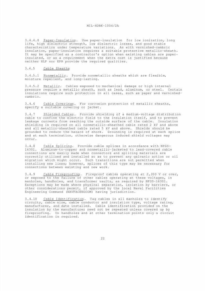
8/14/2019 UFC 3-550-03N 16 January 2004
http://slidepdf.com/reader/full/ufc-3-550-03n-16-january-2004 40/71
MIL-HDBK-1004/2A
22
3.4.4.8 Paper-Insulation. Use paper-insulation for low ionization, long
life, high dielectric strength, low dielectric losses, and good stable
characteristics under temperature variations. As with varnished-cambric
insulation, paper-insulation requires a suitable protective metallic-sheath.It may be specified as a contractor's option when existing cables are paper-
insulated, or as a requirement when the extra cost is justified because
neither XLP nor EPR provide the required qualities.
3.4.5 Cable Sheaths
3.4.5.1 Nonmetallic. Provide nonmetallic sheaths which are flexible,
moisture repellent, and long-lasting.
3.4.5.2 Metallic. Cables exposed to mechanical damage or high internalpressure require a metallic sheath, such as lead, aluminum, or steel. Certain
insulations require such protection in all cases, such as paper and varnished-
cambric.
3.4.6 Cable Coverings. For corrosion protection of metallic sheaths,specify a suitable covering or jacket.
3.4.7 Shielded Cables. Provide shielding of a medium-voltage distribution
cable to confine the electric field to the insulation itself, and to prevent
leakage currents from reaching the outside surface of the cable. Insulation
shielding is required on all nonmetallic-sheathed cable rated 2 kV and aboveand all metallic-sheathed cable rated 5 kV and above. Shields should be
grounded to reduce the hazard of shock. Grounding is required at each splice
and at each termination, otherwise dangerous induced shield voltages may
occur.
3.4.8 Cable Splicing. Provide cable splices in accordance with NFGS-
16301. Aluminum-to-copper and nonmetallic-jacketed to lead-covered cable
connections are easily made when connectors and splicing materials arecorrectly utilized and installed so as to prevent any galvanic action or oil
migration which might occur. Such transitions are not permitted when
installing new lines; however, splices of this type may be necessary forconnections between existing and new work.
3.4.9 Cable Fireproofing. Fireproof cables operating at 2,200 V or over,
or exposed to the failure of other cables operating at these voltages, in
manholes, handholes, and transformer vaults, as required by NFGS-16301.
Exceptions may be made where physical separation, isolation by barriers, orother considerations permit, if approved by the local Naval Facilities
Engineering Command (NAVFACENGCOM) having jurisdiction.
3.4.10 Cable Identification. Tag cables in all manholes to identify
circuity, cable size, cable conductor and insulation type, voltage rating,manufacturer, and date installed. Cable identification provided on the
insulation by the manufacturer need not be repeated unless covered up by
fireproofing. In handholes and at other termination points only a circuit
identification is required.
8/14/2019 UFC 3-550-03N 16 January 2004
http://slidepdf.com/reader/full/ufc-3-550-03n-16-january-2004 41/71
MIL-HDBK-1004/2A
23
3.4.11 Gas Pressurized Cable. Sulfur hexaflouride gas pressurized cable or
integrated gas spacer cable can be considered for use when used with either
XLP or EPR insulations. The jackets of direct-burial cables or field-
installed or factory-coilable conduits can be pressurized with this gas.
3.4.11.1 Sulfur hexaflouride Gas. This gas has five times the density of air
and acts as an "invisible liquid" as it stays in place even when exposed to
air. It is electro-negative with no oxygen or carbon; has a high arc
resistance; will not support combustion; and is odorless, tasteless, andnontoxic. When used with XLP and EPR insulations, it prevents water vapor
diffusion, water treeing, and gaseous ionization. It provides monitoring for
indication of mechanical damage during shipment, installation, and during
operation. Sulfur hexaflouride gas improves the lightning and impulse
strength and can provide a rehealing of insulation after an electromagnetic
pulse insulation failure. The gas pressure protects against internalcorrosion of metal parts. The SF gas provides extra electrical strength in6
splices and terminations.
3.4.11.2 Installation. Expand the requirements for integrated gas spacer
cable of NFPA 70 to cover the XLP or EPR insulation requirement. Determineappropriate installation requirements for direct burial, in conduit, or as
submarine cable from manufacturers. In cold climates, indicate temperature
ranges, so a gaseous mixture which prevents liquification is achieved.
3.4.11.3 Optional Usage. Where adequate requirements are provided, gas
pressurized cable may be used as an option to cables covered in NFGS-16301.
3.5 Underground Transformers. Use vaults to house transformers and
associated equipment for underground distribution systems.
3.5.1 Equipment. Use subway (submersible) type equipment.
3.5.2 Vault Design. Design transformer vaults in accordance with MIL-
HDBK-1008 and include the following provisions:
a) Provide adequate ventilation to prevent a transformer
temperature in excess of the values prescribed in ANSI C57.12.00, GeneralRequirements for Liquid-Immersed Distribution, Power and Regulating
Transformers, and C57.12.01, General Requirements for Dry-Type Distribution
and Power Transformers. This limitation requires that most of the electrical
heat losses must be removed by ventilation; only a minor part can be
dissipated by the vault walls. NFPA 70 recommends 3 inch (19 square cm) of
clear grating area per kilovolt-ampere of transformer capacity. In localitieswith above average temperatures, such as tropical or subtropical areas,
increase the grating area or supplement by forced ventilation, depending upon
temperature extremes.
b) Provide adequate access for repairs, maintenance, andinstallation and removal of equipment. Refer to working space requirements
covered in Section 5.

8/14/2019 UFC 3-550-03N 16 January 2004
http://slidepdf.com/reader/full/ufc-3-550-03n-16-january-2004 42/71
MIL-HDBK-1004/2A
24
c) Provide isolation to prevent transmission of fires or explosions
to adjacent vaults.
d) Provide all vaults with drainage. When normal drainage is notpossible, provide a sump pit to permit the use of a portable pump.
3.6 Cable Ampacities. Design the current-carrying capacities for
underground cables, either direct burial or in ducts, in accordance with NFPA70 adjusted to fit the specific application. The NFPA 70 tables list
individual ampacities for various sizes and number of conductors, with other
assumed conditions, which may or may not apply to the design under
consideration. Parameters given are as follows:
a) An ambient earth temperature of 68 degrees F (20 degrees C).
b) An arrangement with cables spaced either 7.5 inches (190.5 mm)
or 24 inches (609.6 mm) center-to-center.
c) A 100 percent load factor.
d) A thermal resistance (RHO) of 90.
e) A conductor temperature of 194 degrees F (90 degrees C) or 167
degrees F (75 degrees C) dependent upon voltage.
Adjustment factors are given only for different ambient earth temperatures.
No corrections are included for different load factors, thermal resistances,
conductor spacings, or cable temperatures. A load factor of 50 percent and an
RHO of 60 are not unusual which could increase the listed ampacity by as much
as 15 to 50 percent. Detailed calculation methods along with ampacities forother conditions are contained in IEEE/ICEA P-46-426, Power Cable Ampacities.
3.7 Safety Considerations. Effectively ground all electrical equipmentand hardware installed in vaults and manholes by the use of ground rods.
Ground exterior shields of cables as covered previously. Ground metallic
sheaths of cables at each splice and each termination. Bonding together ofmetallic sheaths in a manhole maintains the sheaths at a common potential near
ground and reduces personnel danger and arcing when a cable fault occurs.
Where it is the policy of the facility, a ground conductor may be required to
be installed with each primary feeder and the ground conductor should be
interconnected at manholes and vaults to their grounding systems.

8/14/2019 UFC 3-550-03N 16 January 2004
http://slidepdf.com/reader/full/ufc-3-550-03n-16-january-2004 43/71
MIL-HDBK-1004/2A
25
Section 4: SUBMARINE CABLE SYSTEMS
4.1 Preliminary Considerations
4.1.1 Where Permitted. Use submarine cable only where local conditions
rule out the use of any other system.
4.1.2 Installation Problems. Consider installation problems at the timeof design. These problems (for example, practical length of cables, size of
reels, and transportation to site) will vary for each particular installation.
4.2 Location Considerations. When considering locations, consider the
soundings and the restrictions described in paras 4.2.1 through 4.2.4.
4.2.1 Soundings. Obtain soundings along several proposed crossings to
obtain the most convenient profile. Within the United States, soundings can
be obtained from the Department of the Army, Corps of Engineers. For
locations outside the United States, consult local authorities.
4.2.2 Hydraulic Restrictions
4.2.2.1 Turbulences. Do not install submarine cables in waters where bottom
turbulences may occur. Cables exposed to continuous vibration have short
lives due to mechanical fatigue of metallic sheaths.
4.2.2.2 Currents. Provide cables installed across rivers with currents with
a curved upstream concave alinement. Determination of the amount of curved
alinement necessary depends upon the speed of the current.
4.2.2.3 Variable (Changing) Waters. Obtain approval for routes and minimumdepths for crossings under variable waters from the Department of the Army,
Corps of Engineers or by the corresponding authority.
4.2.3 Chemical Composition of Waters. Do not install submarine cable near
sanitary sewers, chemical discharges, dumping areas, or wharves where waste
material has accumulated. Make a provision based on a water analysis for anychemical reaction with the cable sheaths and coverings. Where feasible,
consider the installation of cable integrally installed in a plastic conduit
or provided with a protective corrosion-resistant jacket.
4.2.4 Marine Traffic. Bury any cables crossing through waters adjacent to
marine traffic to a depth that eliminates any damage from dragging anchors.Large ships may drop anchors up to 15 feet (4.5 m) in depth on sand bottoms.
4.3 Installation. Install cables to lie on the bottom, with ample slack
so that slight shifting will not place excessive strain on them. Because of
the great weights involved when any considerable length of submarine cable isto be sunk across a waterway, use installation methods to keep tensile
stresses at a minimum. The ideal lay of a submarine cable on a bottom is a
series of horizontal S-curves. This pattern provides the slack necessary to
8/14/2019 UFC 3-550-03N 16 January 2004
http://slidepdf.com/reader/full/ufc-3-550-03n-16-january-2004 44/71
MIL-HDBK-1004/2A
26
prevent injurious straining of the cable. Where two parallel cables cross,
provide a separation of 100 feet (30.5 m) to avoid fouling and to permit work
space (refer to criteria in the Underground Systems Reference Book).
4.3.1 Burying Cable. In addition to laying cables on the bottom, considerburying them by the jetwater method. By this technique, the cable is
installed simultaneously with the trenching operation. Several cables or
cables integrally installed in plastic conduits can be installed at the same
time. The installation of cable integrally installed in plastic conduitprovides cable protection and facilitates future replacement.
4.3.2 Anchors. Where a cable crossing is subjected to flow or tidal
currents, anchors are usually required to prevent excessive drifting or
shifting of the cable along the bottom. These anchors can be made fast to the
cable by a series of U-bolts that pass through a common base plate, thusaffording a multiple grip. Either U-bolts, eyebolts, or other means may be
provided for attachment of the anchor cable or chain. Ordinarily, anchors are
masses of concrete large enough to resist current drag.
4.3.3 Warning Signs. Provide suitable warning signs to indicate thelocations of the shore ends of a submarine cable. These signs should state
that ship anchoring is prohibited in the immediate vicinity of the cable.
Signs are required for every submarine cable crossing.
4.3.4 Pile Clusters. Frequently clusters of piles are driven on the
upstream side of important cables where they enter and leave the water. Theseclusters supply visual aid in locating the points where the cable is anchored.
Clusters also provide a certain amount of mechanical protection for
the cables, and furnish platforms on which to mount warning signs.
4.3.5 Maps. The development of accurate maps is one of the most important
steps in an extension of a submarine cable installation. Maps indicate the
exact location of the cable at various points along its length, as establishedby surveying instruments. To estimate cable movement or drifting on the
bottom, the maps must also indicate the exact length of the cable installed
between any two reference points.
4.4 Cable Types. Lead-sheathed cable is generally used for submarine
installations and is usually armored. Insulations shall be Cross-linked
Polyethylene (XLP) or Ethylene-Propylene-Rubber (EPR) except where the paper-
insulated type is justified because it has qualities neither XLP nor EPR
provide. Use multiple-conductor cable unless limited by physical factors.
4.4.1 Metallic-Sheathed Cable. Cables usually are sheathed with copper-
bearing lead, but other alloys may be required where special conditions
warrant nonstandard sheathing.
4.4.2 Armored Cable
8/14/2019 UFC 3-550-03N 16 January 2004
http://slidepdf.com/reader/full/ufc-3-550-03n-16-january-2004 45/71
MIL-HDBK-1004/2A
27
4.4.2.1 Application. Use wire-armored cable where extreme tensile strength
and high resistance to mechanical damage are required. In this type of cable,
asphalt-impregnated-jute usually is applied directly over the lead sheath, and
the wire-armor is applied over the jute to reduce mechanical damage andelectrolytic corrosion. An additional covering of asphalt-impregnated-jute
may be applied over the armor.
4.4.2.2 Wire-Armor. Wire-armor is usually made of galvanized steel wire.The galvanizing protects the armor from corrosion and reduces electrolytic
corrosion of the lead sheath. This reduction, however, may be at the expense
of the armor, because under certain conditions the zinc passes from the armor
to the lead sheath.
4.4.3 Nonmetallic-Sheathed Cable. For submarine service, cables without ametallic sheath are satisfactory for certain applications. When cables
without protective lead sheaths are used, they should be types manufactured
specifically for submarine service. They may or may not require wire armor.
Such cables are provided with insulation of extra thickness for all sizes and
voltages.
4.4.4 Shielding. Nonmetallic-sheathed cables should be shielded
throughout their lengths. Normally the voltage rating will already require
shielding.
4.5 Electrical Connections. Cable termination, splicing, and bonding isas follows:
4.5.1 Terminations
4.5.1.1 Potheads. A lead-covered submarine cable is occasionally connected,at either or both ends, to an overhead line. Under such circumstances, use a
pothead with an integral wiping sleeve as a convenient method of terminating
the cable. This method eliminates the junction box on shore and associatedlabor costs of the extra cable splices. By bringing the submarine cable out
of the ground in a suitable conduit sleeve, or other mechanical protective
arrangement, the cable can be supported on a permanent steel or woodenstructure. Cables in conduit strapped to the supporting structure, are then
run directly into a pothead, which is mounted at the desired height on the
same supporting structure.
4.5.1.2 Three-Conductor Potheads. Adverse atmospheric conditions can make
it dangerous to use three-conductor potheads for such cable terminals. Undersuch conditions, the multiple-conductor cable may be spliced out with single-
conductor cable and single-conductor potheads employed to permit increased
clearances between pothead bushings.
4.5.2 Splices. Use maximum lengths of cables to reduce the number ofsplices. The types of splices shall be in accordance with NFGS-16301.

8/14/2019 UFC 3-550-03N 16 January 2004
http://slidepdf.com/reader/full/ufc-3-550-03n-16-january-2004 46/71
MIL-HDBK-1004/2A
28
4.5.3 Bonding. Cable sheaths and armor shall be bonded together at every
splice and at both shore ends.
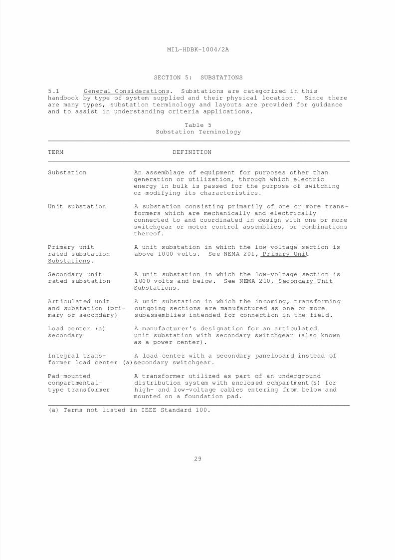
8/14/2019 UFC 3-550-03N 16 January 2004
http://slidepdf.com/reader/full/ufc-3-550-03n-16-january-2004 47/71
MIL-HDBK-1004/2A
29
SECTION 5: SUBSTATIONS
5.1 General Considerations. Substations are categorized in this
handbook by type of system supplied and their physical location. Since thereare many types, substation terminology and layouts are provided for guidance
and to assist in understanding criteria applications.
Table 5Substation Terminology
______________________________________________________________________________
TERM DEFINITION
______________________________________________________________________________
Substation An assemblage of equipment for purposes other than
generation or utilization, through which electric
energy in bulk is passed for the purpose of switching
or modifying its characteristics.
Unit substation A substation consisting primarily of one or more trans-
formers which are mechanically and electrically
connected to and coordinated in design with one or more
switchgear or motor control assemblies, or combinations
thereof.
Primary unit A unit substation in which the low-voltage section is
rated substation above 1000 volts. See NEMA 201, Primary Unit
Substations.
Secondary unit A unit substation in which the low-voltage section israted substation 1000 volts and below. See NEMA 210, Secondary Unit
Substations.
Articulated unit A unit substation in which the incoming, transforming
and substation (pri- outgoing sections are manufactured as one or more
mary or secondary) subassemblies intended for connection in the field.
Load center (a) A manufacturer's designation for an articulated
secondary unit substation with secondary switchgear (also known
as a power center).
Integral trans- A load center with a secondary panelboard instead offormer load center (a)secondary switchgear.
Pad-mounted A transformer utilized as part of an underground
compartmental- distribution system with enclosed compartment(s) for
type transformer high- and low-voltage cables entering from below andmounted on a foundation pad.
______________________________________________________________________________
(a) Terms not listed in IEEE Standard 100.
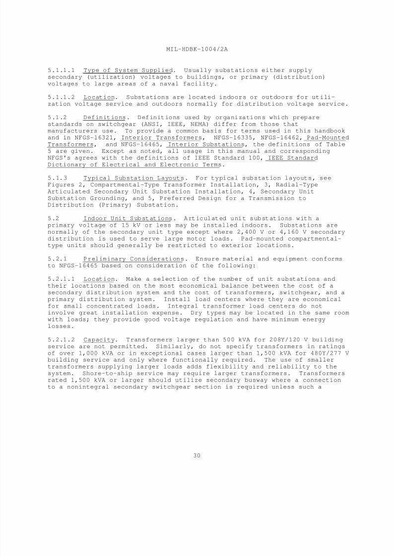
8/14/2019 UFC 3-550-03N 16 January 2004
http://slidepdf.com/reader/full/ufc-3-550-03n-16-january-2004 48/71
MIL-HDBK-1004/2A
30
5.1.1.1 Type of System Supplied. Usually substations either supply
secondary (utilization) voltages to buildings, or primary (distribution)
voltages to large areas of a naval facility.
5.1.1.2 Location. Substations are located indoors or outdoors for utili-zation voltage service and outdoors normally for distribution voltage service.
5.1.2 Definitions. Definitions used by organizations which prepare
standards on switchgear (ANSI, IEEE, NEMA) differ from those thatmanufacturers use. To provide a common basis for terms used in this handbook
and in NFGS-16321, Interior Transformers, NFGS-16335, NFGS-16462, Pad-Mounted
Transformers, and NFGS-16465, Interior Substations, the definitions of Table
5 are given. Except as noted, all usage in this manual and corresponding
NFGS's agrees with the definitions of IEEE Standard 100, IEEE Standard
Dictionary of Electrical and Electronic Terms.
5.1.3 Typical Substation Layouts. For typical substation layouts, see
Figures 2, Compartmental-Type Transformer Installation, 3, Radial-Type
Articulated Secondary Unit Substation Installation, 4, Secondary Unit
Substation Grounding, and 5, Preferred Design for a Transmission toDistribution (Primary) Substation.
5.2 Indoor Unit Substations. Articulated unit substations with a
primary voltage of 15 kV or less may be installed indoors. Substations are
normally of the secondary unit type except where 2,400 V or 4,160 V secondary
distribution is used to serve large motor loads. Pad-mounted compartmental-type units should generally be restricted to exterior locations.
5.2.1 Preliminary Considerations. Ensure material and equipment conforms
to NFGS-16465 based on consideration of the following:
5.2.1.1 Location. Make a selection of the number of unit substations and
their locations based on the most economical balance between the cost of a
secondary distribution system and the cost of transformers, switchgear, and aprimary distribution system. Install load centers where they are economical
for small concentrated loads. Integral transformer load centers do not
involve great installation expense. Dry types may be located in the same roomwith loads; they provide good voltage regulation and have minimum energy
losses.
5.2.1.2 Capacity. Transformers larger than 500 kVA for 208Y/120 V building
service are not permitted. Similarly, do not specify transformers in ratings
of over 1,000 kVA or in exceptional cases larger than 1,500 kVA for 480Y/277 Vbuilding service and only where functionally required. The use of smaller
transformers supplying larger loads adds flexibility and reliability to the
system. Shore-to-ship service may require larger transformers. Transformers
rated 1,500 kVA or larger should utilize secondary busway where a connection
to a nonintegral secondary switchgear section is required unless such a

8/14/2019 UFC 3-550-03N 16 January 2004
http://slidepdf.com/reader/full/ufc-3-550-03n-16-january-2004 49/71
MIL-HDBK-1004/2A
31
connection is impracticable. Where larger transformer capacities are
justified, provide current-limiting fuses in conjunction with primary or
secondary protective devices or other methods of limiting the available fault
current to an acceptable value.
5.2.1.3 Safety. All current-carrying parts of unit substations must be
dead-front construction, usually in grounded metal enclosures. In some cases,
nonmetallic enclosures, such as fiberglass may be functionally required.
Provide interlocking to prevent accidental contact with live parts whenworking within the switchgear enclosure. For example, interlock access doors
to primary fuse compartments so that access is possible only when the primary
switch is open.
5.2.2 Design. A unit substation, by its definition, has coordinated
sections; therefore, provisions for future addition are possible at minimumcost, if adequate space is provided.
5.2.2.1 Mounting. Provide a concrete base. Mount substations on channels
or other supports which are flush with the top of the base.
5.2.2.2 Short-Circuit Duty. Coordinate circuit interrupting devices with
each other. Each device shall be capable of clearing the maximum fault
available. Bracing for bus bars and other current-carrying parts should be
capable of withstanding the mechanical stresses produced by the maximum
available short-circuit current.
5.2.2.3 Primary Protection. Use air-type load interrupter switches with
current-limiting fuses, unless other protection such as circuit breakers or
liquid-type switches are more appropriate. Use of circuit breakers may be
required to provide sufficient interrupting duty, or because coordinated
tripping is required. Circuit breakers are more reliable than switches, buttheir additional cost must be justified. Use of liquid-immersed switches is
appropriate for certain installations, such as in underground vaults.
5.2.2.4 Lightning Protection. Coordinate lightning protection with other
components of the distribution system that may be exposed to surge voltages.
Provide arresters when necessary. When dry-type transformers with lowerBIL???? ratings are used, extra protection may be required.
5.2.2.5 Secondary Protection. Use either metal-enclosed, low-voltage power
or molded-case circuit breakers as protection. Normally for building
services, molded-case units are used for less than 1,200 A and low-voltage
power units are used for higher amperages. For shore-to-ship service, lowvoltage power units are required.
5.2.2.6 Instrumentation. Provide unit substations of more than 500 kVA with
at least an ammeter and a secondary voltmeter. The use of wattmeters
(recording or indicating) and voltmeters, for primary service metering, willdepend on the individual installation. For provision of watthour demand
meters with pulse initiators, see requirements for energy monitoring in this
section.

8/14/2019 UFC 3-550-03N 16 January 2004
http://slidepdf.com/reader/full/ufc-3-550-03n-16-january-2004 50/71
MIL-HDBK-1004/2A
32
5.2.3 Arrangements. Use standard arrangements where possible. Standard
unit substations have the primary switch on the left, the transformer in the
middle, the circuit breakers on the right, and space for future additions.
5.2.3.1 Reversed. Where conditions dictate otherwise, the reversed
arrangement may be adopted.
5.2.3.2 Double-Ended. Use double-ended unit substations where two primarysources are required to provide reliability. See Figure 6 for a layout of a
secondary-selective-type double-ended arrangement. Each transformer and its
associated equipment shall be capable of carrying the essential loads of both
sections. Refer to MIL-HDBK-1004/1 for additional policy on selection of
electric power sources for standby service. In sizing the transformers, take
into consideration allowable overloading. Refer to ANSI C57.91, C57.92, orC57.96, for overloading. Where the normal double-ended unit substation is
used, provide for contemplated future expansion; this arrangement does not
permit addition of unexpected future circuit breakers. For applications where
future expansion may be greater than normal, or unpredictable, consider two
other arrangements requiring more floor area and initial cost, but whichpermit easy addition of sections, or replacement of transformers with larger
units. One arrangement has the primary, transforming, and secondary sections
for each half in separate lineups, with a tie bus or conduit and wire
connecting the two. The tie breaker may be in either lineup. The other
arrangement has the primary and transforming sections, along with the
secondary main breakers separate from the secondary lineup.
5.2.3.3 Secondary Spot-Network. Use secondary spot-network unit substations
for loads requiring an unusually high service reliability where the increased
cost can be justified. Figure 2 would represent a secondary spot-network
substation with a two-transformer input to a multiple-feeder output, if thetie circuit breaker were eliminated and the secondary main circuit breakers
were shown with network protectors. This system is the most reliable power
supply for large loads, since any fault on the primary input to the secondarybus is automatically disconnected by the network protector operating at a
speed which greatly minimizes voltage dips from faults or large transient
loads. The extra cost of the additional transformers and network protectorsplus possible increased secondary duty ratings from the increased short-
circuit capacity of parallel transformers makes this a very expensive
installation, especially when in the usual case, three or four transformers
are paralled.
5.2.4 Transformer Insulations. Indoor unit substation transformers of thedry-type may be used and need not be installed in vaults. Less-flammable,
liquid-insulated units may be installed without a vault where permitted by
NFPA 70. Where vaults are required for less-flammable, liquid-insulated
transformers in some cases and in all cases for oil-insulated transformers,
their installation shall conform to NFPA 70. Provide an economic or
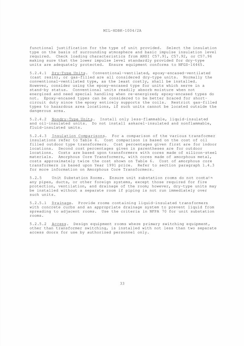
8/14/2019 UFC 3-550-03N 16 January 2004
http://slidepdf.com/reader/full/ufc-3-550-03n-16-january-2004 51/71
MIL-HDBK-1004/2A
33
functional justification for the type of unit provided. Select the insulation
type on the basis of surrounding atmosphere and basic impulse insulation level
required. Check loading characteristics from ANSI C57.91, C57.92, or C57.96
making sure that the lower impulse level standardly provided for dry-typeunits are adequately protected. Ensure equipment conforms to NFGS-16465.
5.2.4.1 Dry-Type Units. Conventional-ventilated, epoxy-encased-ventilated
(cast resin), or gas-filled are all considered dry-type units. Normally theconventional-ventilated type, as the least costly, shall be installed.
However, consider using the epoxy-encased type for units which serve in a
stand-by status. Conventional units readily absorb moisture when not
energized and need special handling when re-energized; epoxy-encased types do
not. Epoxy-encased types can be considered to be better braced for short-
circuit duty since the epoxy entirely supports the coils. Restrict gas-filledtypes to hazardous area locations, if such units cannot be located outside the
dangerous area.
5.2.4.2 Nondry-Type Units. Install only less-flammable, liquid-insulated
and oil-insulated units. Do not install askarel-insulated and nonflammable,fluid-insulated umits.
5.2.4.3 Insulation Comparisons. For a comparison of the various transformer
insulations refer to Table 6. Cost comparison is based on the cost of oil
filled outdoor type transformers. Cost percentages given first are for indoor
locations. Second cost percentages given in parentheses are for outdoorlocations. Costs are based upon transformers with cores made of silicon-steel
materials. Amorphous Core Transformers, with cores made of amorphous metal,
costs approximately twice the cost shown on Table 6. Cost of amorphous core
transformers is based upon Year 1991 price. Refer to section paragraph 1.4.3
for more information on Amorphous Core Transformers.
5.2.5 Unit Substation Rooms. Ensure unit substation rooms do not contain
any pipes, ducts, or other foreign systems, except those required for fireprotection, ventilation, and drainage of the room; however, dry-type units may
be installed without a separate room if piping is not run immediately over
such units.
5.2.5.1 Drainage. Provide rooms containing liquid-insulated transformers
with concrete curbs and an appropriate drainage system to prevent liquid from
spreading to adjacent rooms. Use the criteria in NFPA 70 for unit substation
rooms.
5.2.5.2 Access. Design equipment rooms where primary switching equipment,
other than transformer switching, is installed with not less than two separate
access doors for use by authorized personnel only.
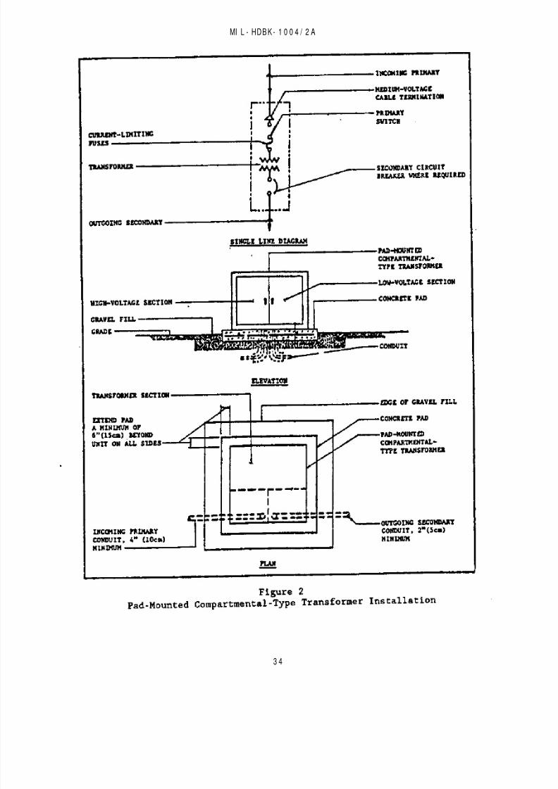
8/14/2019 UFC 3-550-03N 16 January 2004
http://slidepdf.com/reader/full/ufc-3-550-03n-16-january-2004 52/71
MI L - HDBK - 1 0 0 4 / 2 A
3 4

8/14/2019 UFC 3-550-03N 16 January 2004
http://slidepdf.com/reader/full/ufc-3-550-03n-16-january-2004 53/71
MI L - HDBK - 1 0 0 4 / 2 A

8/14/2019 UFC 3-550-03N 16 January 2004
http://slidepdf.com/reader/full/ufc-3-550-03n-16-january-2004 54/71
MI L - HDBK - 1 0 0 4 / 2 A
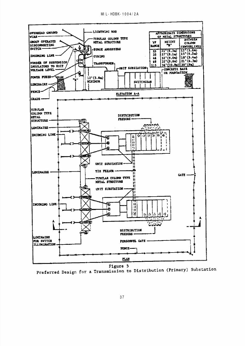
8/14/2019 UFC 3-550-03N 16 January 2004
http://slidepdf.com/reader/full/ufc-3-550-03n-16-january-2004 55/71
MI L - HDBK - 1 0 0 4 / 2 A
3 7

8/14/2019 UFC 3-550-03N 16 January 2004
http://slidepdf.com/reader/full/ufc-3-550-03n-16-january-2004 56/71
MI L - HDBK - 1 0 0 4 / 2 A
3 8

8/14/2019 UFC 3-550-03N 16 January 2004
http://slidepdf.com/reader/full/ufc-3-550-03n-16-january-2004 57/71
MIL-HDBK-1004/2A
39
5.2.5.3 Ventilation. Provide ventilation adequate to dissipate heat given
off by transformers and associated equipment and to maintain safe operating
temperatures. Gravity ventilation is usually not adequate for indoor
substation rooms; in such cases, mechanical ventilation should be provided.
In air-conditioned buildings, an economical and positive means of ventilatingsubstation rooms is to exhaust tempered air from conditioned spaces through
the substation room.
Table 6
Comparison of Types of Transformer Insulation
______________________________________________________________________________
LIQUID-INSULATEDDRY-TYPE
TRANSFORMERQUALITIES OIL LESS- CONVENTIONAL EPOXY- GAS-
FLAMMABLE ENCASED FILLED
______________________________________________________________________________
Relative 100% 100% Varies(1) Varies(1) Varies(1)
Impulse strength(BIL)
Temperature 55 or 65 55 or 65 80 or 150 80 or 150 120
rating(degree C)
Relative X X X + 10 dB X + 10 dB X + 10 dBaudio sound
level in dB (2)
Relative weight 100% 120% 80% 95%
125% :
Relative 100% 100% 100% 105% 120%
dimensions
Application outdoor(3) all indoor all (4) all
Maintenance routine routine routine routine low
Relative Cost 237% (100%) 200% (130%) 125% (127%) 200% (200%)
220% (220%)
______________________________________________________________________________
(1) Varies from 33 to 66% depending on voltage level. Higher BIL ratings fordry-type transformer are available, but an increased cost for conventional
and gas-filled types.
(2) X indicates normal decibel level for liquid-immersed units.
(3) Indoor also in fire-resistant vaults when more economical than other
types.(4) Not recommended in extreme environment containing excessive dirt or dust
or containing concentration of corrosive elements.
8/14/2019 UFC 3-550-03N 16 January 2004
http://slidepdf.com/reader/full/ufc-3-550-03n-16-january-2004 58/71
MIL-HDBK-1004/2A
40
5.2.5.4 Noise. If local conditions require less than NEMA TR-1 recommended
audio sound levels, make an economic comparison between the cost of
transformers having lower than standard noise levels, and the cost of sound
and vibration isolation of the transformer room. Avoid locating unitsubstation rooms near critical spaces requiring low noise levels, such as
auditoriums, sick bays, or living quarters (refer to NAVFAC DM-1.03,
Architectural Acoustics).
5.2.5.5 Emergency Lighting. Provide emergency lighting, of the battery-
operated type, in unit substation rooms.
5.3 Outdoor Utilization Voltage Substations. Base material and
equipment on NFGS-16335. Generally, transformers are be grade-mounted type
subject to the limitation given in this section. Transformers may be pole-mounted type only when such transformers comply with the requirements given in
Section 2.
5.3.1 Secondary Unit Substation Types. Secondary unit substations should
generally follow the criteria given previously for indoor unit substationsexcept that requirements for outdoor installations apply. Because these units
are not tamperproof, protect substations from unauthorized access by chain
link fencing of at least 7 feet (2.1 m) in height as a minimum requirement.
Provide three strands of barbed wire above for additional protection only
where such substations are in housing areas or otherwise exposed to military
dependents or where required by the using agency. Other fence materials toprovide equipment masking, sound absorption, or protection against sabotage
may be necessary in some cases (see Figure 3).
5.3.2 Pad-Mounted Compartmental-Type Transformer Units. Provide units in
accordance with the requirements of NFGS-16462. This specification limits theprimary protective options to group-operated, load-break switches. Since such
units are tamper resistant, they need not be fence-enclosed (see Figure 2).
5.3.2.1 Units 500 Kilovolt-Amperes and Smaller Units are not Provided with
Either Taps or a Minimum Percent Impedance Unless Specified. To prevent
excessive interrupting duty on secondary equipment it may be necessary tocheck manufacturers' ranges of available impedances, as there is no industry
standard.
5.3.2.2 Units Larger than 500 kVA. Pad-mounted units in three-phase units
larger than 500 kVA are available up to a capacity of 2,500 kVA. These units
are less expensive than secondary substation units. However, because primaryprotective devices available for such larger sizes do not provide dead-front
load-break features within the pad-mount construction, the use of units larger
than 750 kVA is not recommended.
5.4 Outdoor Distribution Voltage Substations. Design these substationsto meet the criteria for acceptable power sources in MIL-HDBK-1004/1 and the
recommendations of the Base Exterior Architecture (BEA) plan.

8/14/2019 UFC 3-550-03N 16 January 2004
http://slidepdf.com/reader/full/ufc-3-550-03n-16-january-2004 59/71
MIL-HDBK-1004/2A
41
5.4.1 Structure-Mounted Equipment. Structure-mounted equipment should be
used for voltages above 35 kV. The use of modern low-profile metal structures
with tubular type or H-beam supports is considered the most desirable design.
The conventional lattice-type structure is unattractive in appearance, more
difficult to maintain, and more vulnerable to the twisting forces from heavywinds (see Figure 5).
5.4.2 Transformers. Primary unit substations require less land space, are
visually less objectionable, and because of the integrated transformer tosecondary connection, are more reliable than separate substation transformers
and secondary protective devices.
5.4.3 Connection to Primary Distribution Lines. An underground connection
from the station to aerial lines should be provided when distribution voltage
is 35 kV or less. An underground line not only provides aesthetic enhancementbut reduces vulnerability to lightning or other weather or man-produced
interruptions.
5.5 Substation Considerations. Consider the effects that the actual
site electrical configuration, type of incoming and outgoing switching, needfor supporting structures and surge protection, type of transformers, and
control features have on a substation layout.
5.5.1 Site Effects. In the design of a substation, consider the following
factors:
a) Architectural requirements; landscaping.
b) Exposure conditions; for example, at the seashore or in other
corrosion-producing atmospheres.
c) Physical conditions such as snow or ice, sandstorms, altitude,and lack of rainfall.
d) Adjacent terrain and installations affect landscaping layout andnoise treatment. Utilize the influence of the direction of prevailing winds
on sound propagation to minimize noise exposure (refer to NAVFAC DM-1.03).
5.5.2 Electric Configuration. Determine the electrical configuration with
the respect to provisions for adequate station capacity plus supply and feeder
circuit conditions. Consider supply circuit requirements for the following
conditions:
a) single or multiple supply,b) supply circuit voltage and phases,
c) overhead or underground supply required, and
d) primary switching.
For feeder or load circuits, determine the following conditions:
8/14/2019 UFC 3-550-03N 16 January 2004
http://slidepdf.com/reader/full/ufc-3-550-03n-16-january-2004 60/71
MIL-HDBK-1004/2A
42
a) number of circuits,
b) capacity of circuits,
c) voltage and phase, and
d) overhead or underground distribution required.
Finally, consider coordination of circuit protective devices between supply
and feeder circuits.
5.5.3 Incoming-Line Switching. Design the substation with a minimum of
incoming-line switching consistent with good maintenance and operation. For
rating of equipment, refer to MIL-HDBK-1004/3, Switchgear and Relaying. Also,
consider the methods described in paras 5.5.3.1 through 5.5.3.3.
5.5.3.1 Circuit Breakers. Use circuit breakers only when the circuitinterrupting or relaying requirements do not allow the use of switches.
Provide a disconnect and bypass switching features where drawout circuit
breakers cannot be utilized.
5.5.3.2 Switches. Switches are covered in Section 2 of this handbook. Forvoltages of 15 kV or less, load interrupter or disconnect switches are
available. Load interrupter switches disconnect circuits under fully loaded
conditions and are therefore usually the most desirable choice. Use
disconnect switches only to interrupt transformer exciting currents. The use
of disconnect switches is not recommended, except for primary incoming lines
where secondary circuit breakers can interrupt loads. Assure that operatorsdo not open disconnect switches under load, either by interlocking with load
switching equipment or by operating procedures.
5.5.3.3 Current Limiting Protectors. Current limiting protection devices
are covered in Section 2. They are generally inappropriate for substation usewhere metal-enclosed or metal-clad switchgear for 15-kV applications provides
a more desirable design.
5.5.4 Outgoing-Feeder Switchgear. For ratings and selection of equipment,
refer to MIL-HDBK-1004/3.
5.5.4.1 600 V and Less. For load circuits below 600 V, select from one of
the following:
a) metal-enclosed (low-voltage power) circuit breakers where
reliability and the longer withstand rating period are desirable; or
b) molded-case circuit breakers. Molded-case circuit breakers must
be further defined as to tripping and interrupting currents and whether fully-
rated capability or other features are desirable. The use of the term
"insulated case" conveys no minimum requirements in accordance with any
recognized industry specification and should not be used.

8/14/2019 UFC 3-550-03N 16 January 2004
http://slidepdf.com/reader/full/ufc-3-550-03n-16-january-2004 61/71
MIL-HDBK-1004/2A
43
5.5.4.2 Over 600 Volts. For load circuits over 600 V, use criteria in MIL-
HDBK-1004/3 to select from the following:
a) either oilless, metal-clad, medium-voltage circuit breakers,
preferably of the vacuum circuit breaker type; or
b) grounded, metal-tank type, frame-mounted circuit breakers, with
open disconnecting switches. Circuit breakers may be oil, gas, vacuum, orcompressed air type. Oil-insulated type shall be installed only in outdoor
locations and only for voltages exceeding 35 kV.
5.5.5 Substation Structures. Depending on the chosen design, the
substation structure may consist of the following:
a) flat concrete base without elevated structures, applicable for
underground supply and load circuits served by metal-clad switchgear;
b) steel or aluminum superstructures mounted on concrete piers; or
c) a combination of either of the aforementioned systems.
5.5.6 Transformers
5.5.6.1 Selection. Consider the types of insulation that are suitable for
the site and the system voltages (see Table 6). Select oil-insulated foroutdoor applications, except where fire safety considerations require the use
of less-flammable, liquid-insulated insulation which is not usually available
for voltages above 34.5 kilovolts. For indoor installations, see the
paragraph on transformer insulations of this section.
5.5.6.2 Cooling. Forced cooled ratings are only available on larger size
transformers; check their availability before specifying. Dependent upon
standard ratings and overload capacity calculations, specify the coolingmethod from one of the following:
a) self-cooled, type OA,b) one-stage forced-cooled, type FA,
c) two-stage forced-cooled, type OA/FA,
d) one-stage double-forced-cooled; forced-oil, forced-air, type FOA,
or
e) triple-rated, types OA/FA/FOA/ or OA/FA/FA.
5.5.6.3 Transformer Capacity. Choose the transformer rating by considering
the maximum load to be carried for normal and contingency conditions and the
possibility of accepting overloading with accelerated loss of system life.
Transformers should be sized for 10 to 25 percent more than calculated loads
to minimize future growth costs.
5.5.6.4 Fire Protection. For minimum safe distances of transformers to
buildings and other fire protection criteria, refer to MIL-HDBK-1008. Also
refer to IEEE 979, Guide for Substation Fire Protection.

8/14/2019 UFC 3-550-03N 16 January 2004
http://slidepdf.com/reader/full/ufc-3-550-03n-16-january-2004 62/71
MIL-HDBK-1004/2A
44
5.5.6.5 Transformer Noise. Specify transformer noise levels as given in NEMA
TR-1. When standard noise levels are found to be too high, estimate the cost
effectiveness of sound minimizing methods such as:
a) specifying a transformer with a lower noise level,
b) utilizing sound barriers, or
c) designing a sound-absorbing enclosure.
5.5.7 Lightning Protection. Where supply or load circuits are overhead or
when equipment is located on elevated structures, lightning protection is
required in all areas, except those with few lightning storms annually. Data
on the mean annual number of thunderstorm days in the continental United
States is given in NFPA 78, Lightning Protection Code. Local practice for
lightning protection should be followed. Install lightning rods on substationsuperstructures where required for lightning protection. Surge (lightning)
arresters are required at all elevated structures for each circuit, for
ground-mounted equipment served by overhead lines and not within the
protective range of other arresters, and elsewhere where surges could damage
equipment. Determine ratings of arresters according to the equipment to beprotected, impulse insulation levels of equipment, and the expected discharge
currents the arrester must withstand. Arresters are designed to discharge
surges and are classed according to their protective level. They are
constructed in various ways to provide nonlinear volt-time characteristics.
The National Rural Electric Cooperative Association (NRECA) Research Project
82-5, Lightning Protection Manual for Rural Electric Systems provides a sourceof information concerning lightning protection for distribution systems.
5.5.7.1 Classes. Select class of arrester based on the following guidelines:
a) Use station-class surge arresters on substations with incomingand outgoing aerial circuits above 15 kV.
b) Use intermediate-class surge arresters on substations withincoming and outgoing aerial circuits above 600 V to 15 kV, except where
station-class arresters are required on transformer terminals to provide
adequate protection.
c) Use distribution-class arresters at substations where they
provide adequate protection for switchgear and as backup protection for
arresters located at the junction of overhead and underground incoming and
outgoing lines.
5.5.7.2 Types. Arresters are designed so that at power frequencies current
does not flow, but at a level of overvoltage which would damage system
insulation, the arrester provides a low-impedance path to discharge lightning
induced or other high frequency power surges.

8/14/2019 UFC 3-550-03N 16 January 2004
http://slidepdf.com/reader/full/ufc-3-550-03n-16-january-2004 63/71
MIL-HDBK-1004/2A
45
The silicon-carbide valve arrester has an element with nonlinear
volt-ampere characteristics which limits the follow current to a value that
the series gap can interrupt. This type is being phased out by manufacturers.
The metal-oxide varistor type arrester provides the most modern
solution to the problems resulting from surge voltages, since its gapless
construction means there is no volt-time-gap sparkover characteristic to be
considered.
5.5.7.3 Additional Requirements. Refer to MIL-HDBK-1004/6 for additional
lightning protection criteria.
5.5.8 Control Features
5.5.8.1 Instrumentation. Instrumentation should be in accordance with
metering and relaying requirements of MIL-HDBK-1004/3.
5.5.8.2 Energy Monitoring. Check local energy monitoring requirements to
assist in energy conservation and appropriate load shedding. In general,instrument transformers belonging to a utility company cannot be used for
monitoring. Watthour meters at distribution substations should be of the
pulse initiator type. At utilization substations, it is suggested that
watthour meters be provided with the pulse initiator feature, as the cost is
not excessive. While the use of instantaneous and peak demand wattmeters for
all transformers larger than 500 kVA is recommended, actual provisions shouldbe those required by the activity. As a minimum, always provide at all new
distribution substations, conduit installed to the location selected for a
future monitoring panel from the following points:
a) energy sensing instrument transformers,b) a 120 V power source, and
c) a communication line tie-in.
5.5.8.3 Control Cables. For control cables refer to IEEE No. 525, Guide for
the Selection and Installation of Control and Low-Voltage Cable Systems in
Substations.
5.6 Substation Working Space and Access Requirements. Design indoor and
outdoor substation layouts to provide safe working space and access to meet
the requirements of NFPA 70 keeping in mind any need for installing and
removing equipment, vehicle access necessary for outdoor substations, and
adequacy of floor or foundations to support equipment weights.
5.6.1 Design. Allocate adequate space early in the programming/planning
stages. Future expansion space should be clearly delineated as should safety
exit requirements. Interior space for substations is always at a premium,
which can be further minimized by the intrusion of structural elements orinstallation of mechanical equipment. Electrical requirements are often
underestimated.

8/14/2019 UFC 3-550-03N 16 January 2004
http://slidepdf.com/reader/full/ufc-3-550-03n-16-january-2004 64/71
MIL-HDBK-1004/2A
46
5.6.2 Existing Construction. When electrical upgrading of existing
construction is involved, take into account any extra space and costs required
to meet current NFPA 70 code requirements. Working space and access
requirements have become more stringent as successive codes are issued and
many existing vaults or substation installations may not meet currentcriteria. If the design cannot meet current NFPA 70 requirements, then a
waiver must be obtained from the proper authority.
5.7 Grounding. Provide a grounding electrode system for each substationand connect equipment and system grounds so as to provide personnel and
equipment protection and grounding continuity.
5.7.1 Grounding Electrode Systems. Provide electrode systems made of
either the girdle or grid type using horizontal conductors running between
vertical ground rods.
5.7.1.1 Girdle Type. Use girdle type systems for pad-mounted com-partmental-
type transformers and secondary unit substations (see Figure 4).
5.7.1.2 Grid Type. For the much larger voltage gradients at substations forutility-Navy interconnections use the grid-type, buried grounding network.
Mesh spacings of 10 to 12 feet (3 to 3.5 m) are commonly used and normally
such spacings can control surface voltage gradients even though the ground
resistance may be relatively high.
5.7.1.3 Special Techniques. See recommendations of IEEE 80, Guide for Safetyin Substation Grounding. Where the local utility or activity indicates the
special grounding techniques are necessary because of poor soil conductivity,
their recommendations should be followed. Refer to IEEE 142,
Recommended Practice for Grounding of Industrial and Commercial Power Systems
for a discussion of soil resistivity. Refer to NFGS-16302 for maximumallowable ground resistance values.
5.7.2 Equipment Grounding. Ground metallic enclosures, including cases ofprimary and secondary switchgear and transformers, to protect operating
personnel.
5.7.3 System Grounding. Unless functional requirements prohibit grounding,
provide all transformers with wye-connected neutral connections grounded
independently at each voltage level, that is, at the transformer secondary.
5.7.3.1 Neutral Grounding. Normally, provide solid grounding, since this is
the least expensive method of limiting transient overvoltages while obtainingsufficient ground fault current for selective tripping. Provide impedance
grounding only when required to limit ground fault currents to acceptable
values or where required by code, such as for portable substations or to match
existing system design. Refer to MIL-HDBK-1004/1 for additional requirements.
8/14/2019 UFC 3-550-03N 16 January 2004
http://slidepdf.com/reader/full/ufc-3-550-03n-16-january-2004 65/71
MIL-HDBK-1004/2A
47
5.7.3.2 Ground Fault Protection. Ground-fault protection for each system
voltage level is independent of the protection at voltage levels for
transformers connected delta-wye or delta-delta. A circuit breaker having
ground fault protection can be set to operate for lower ground fault levelsand provides fast operation since no downstream coordination is required.
Fuses have fixed time-current characteristics. On secondary unit substations,
low-voltage circuit breakers with ground fault tripping should be used on
mains and on large or important feeder units as a minimum, if selectivity canbe achieved. On distribution substations, the additional cost for circuit
breakers must be justified on the basis that the improved selectivity is
required for reliability. Refer to IEEE 242, Recommended Practice for
Protection and Coordination of Industrial and Commercial Power Systems, for
ground fault protection application data.
5.7.4 Grounding Continuity. The most important consideration in grounding
is assuring continuity of the grounding system. Provide special danger points
such as metal-structure mounted switches and surge arresters of transmission
to distribution substations (see Figure 5) with dual ground paths. Ground
wires run with primary feeder cables may be required either because ofexisting station practice or for other reasons.
5.7.4.1 Fault Current. NFPA 70 requires a low impedance ground path for
fault currents. Where reliable low impedance paths for utilization
substations cannot be provided because of soil conditions, equipment
locations, or other factors, install a ground wire with the primary feedercable back to the distribution system substation.
5.7.4.2 Portable Substations. NFPA 70 requires that the exposed noncurrent-
carrying metal parts of portable substations must be connected with an
equipment grounding conductor run with the primary feeder back to the pointwhere the system neutral impedance is grounded. The reason for such a
requirement is that the mobility of the portable substation precludes a
predesigned grounding electrode system.
5.8 Safety Considerations. Provide for public safety and for protection
of operating personnel with respect to the factors described in paras. 5.8.1through 5.8.5.
5.8.1 Fencing. Connect fencing, including gates, to substation grounding
(refer to DM-5.12, Fencing, Gates, and Guard Towers). For aesthetic reasons,
plastic-coated fabric may be used. Grounding this type of fabric requires
removing the coating to get a good ground. A touch-up plastic should recoatany uncoated areas not covered by the ground connection. Application and
material should be as recommended by the fence manufacturer.
5.8.2 Metal Enclosures. For personnel safety, use metal or fiberglass
enclosures around all live parts.
5.8.3 Locking of Gates. Provide locks on gates. Interlock switchgear
doors to prevent access to live parts.

8/14/2019 UFC 3-550-03N 16 January 2004
http://slidepdf.com/reader/full/ufc-3-550-03n-16-january-2004 66/71
MIL-HDBK-1004/2A
48
5.8.4 Bonding of Gates. For grounding purposes, provide gates with bonding
straps across hinges.
5.8.5 Legal Warning Signs. Legal warning signs are required on fences and
electrical equipment enclosures which are unfenced. Guidance for warningsigns in family housing and community center areas is given in NEMA 260,
Safety Labels for Padmounted Switchgear and Transformers Sited in Public
Areas.

8/14/2019 UFC 3-550-03N 16 January 2004
http://slidepdf.com/reader/full/ufc-3-550-03n-16-january-2004 67/71
MIL-HDBK-1004/2A
49
REFERENCES
ANSI Standards, American National Standards Institute (ANSI), 1430 Broadway,
New York, NY 10018.
ANSI C2-90 National Electrical Safety Code
ANSI C29.1-88 Test Methods for Electrical Power Insulators
ANSI C29.2-83 Insulators, Wet-Process Porcelain and
Toughened Glass, Suspension Type
ANSI C29.3-86 Wet-Process Porcelain Insulators, Spool Type
ANSI C29.4-89 Wet-Process Porcelain Insulators, Strain Type
ANSI C29.5-84 Wet-Process Porcelain Insulators, Low- and
Medium-Voltage Types
ANSI C29.6-84 Wet-Process Porcelain Insulators, High-Voltage Pin Type
ANSI C29.7-83 Wet-Process Porcelain Insulators, High
-Voltage Line-Post Type
ANSI C29.8-85 Wet-Process Porcelain Insulators, ApparatusCap and Pin Type
ANSI C29.9-83 Wet-Process Porcelain Insulators, Apparatus
Post-Type
ANSI C37.30-71 Definitions and Requirements for High-Voltage
Air Switches, Insulators, and Bus Supports
ANSI C37.32-90 Schedules of Preferred Ratings, Manufacturing
Specifications, and Application Guide for
High-Voltage Air Switches, Bus Supports, andSwitch Accessories
ANSI C57.12.00-87 Standard Requirements for Liquid-Immersed
Distribution, Power, and Regulating
Transformer
ANSI C57.12.01-79 General Requirements for Dry-Type
Distribution and Power Transformers
ANSI C57.12.20-88 Requirements for Overhead Type Distribution
Transformers, 500 kVA and Smaller: High-Voltage 67,000 Volts and Below; Low-Voltage
15,000 Volts and Below

8/14/2019 UFC 3-550-03N 16 January 2004
http://slidepdf.com/reader/full/ufc-3-550-03n-16-january-2004 68/71
MIL-HDBK-1004/2A
50
ANSI C57.91-81 Guide for Loading Mineral-Oil-Overhead and
Pad-Mounted Distribution Transformers Rated
500 kVA and Less with 65 Degrees C or 55
Degrees C Average Winding Rise
ANSI C57.92-81 Guide for Loading Mineral-Oil-Immersed Power
Transformers up to and Including 100 MVA with
55 Degrees C or 65 Degrees C Winding Rise
ANSI C57.96-89 Guide for Loading Dry-Type Distribution and
Power Transformers
ANSI C62.1-84 Surge Arresters for AC Power Circuits
ANSI C62.2-87 Guide for Application of Valve-Type SurgeArresters for Alternating Current Systems
ANSI C62.33-82 Varistor Surge Protective Devices
Electrical Transmission and Distribution Reference Book, Central StationEngineers, Westinghouse Electric Corporation, Pittsburgh, PA 15230, 1964
Electrical Utility Engineering Reference Book, Distribution Systems,
Electrical Utility Engineers, Westinghouse Electric Corporation, East
Pittsburgh, PA 15230, 1965.
Industrial Power Systems Handbook, Donald Beeman, Editor, McGraw Hill Book
Company, New York, NY 10020, 1955.
Institute of Electrical and Electronic Engineers (IEEE), 345 East 47th Street,
New York, NY 10017. The following publications are IEEE Standards.
IEEE 18-80 Shunt Power Capacitors
IEEE 80-86 Guide for Safety in Substation Grounding
IEEE 100-88 IEEE Standard Dictionary of Electrical andElectronics Terms
IEEE 141-86 Recommended Practice for Electric Power
Distribution For Industrial Plants
IEEE 142-82 Recommended Practice for Grounding ofIndustrial and Commercial Power Systems
IEEE 242 Recommended Practice for Protection and
Coordination of Industrial and Commercial
Power Systems
8/14/2019 UFC 3-550-03N 16 January 2004
http://slidepdf.com/reader/full/ufc-3-550-03n-16-january-2004 69/71
MIL-HDBK-1004/2A
51
IEEE 525-87 Guide for the Selection and Installation of
Control and Low-Voltage Cable Systems in
Substations
IEEE 979-84 Guide for Substation Fire Protection
IEEE/ICEA P-46-426 Power Cable Ampacities, 1962
National Electric Safety Code (NESC) Handbook by Allen L. Clapp, 1984
NAVFAC Guide Specifications and Military Handbooks, available from
Standardization Document Order Desk, Building 4D, 700 Robbins Avenue,Philadelphia, PA 19111-5094.
NFGS-02225 Excavation, Backfilling, and Compacting for
Utilities
NFGS-16301 Underground Electrical Work
NFGS-16302 Overhead Electrical Work
NFGS-16321 Interior Transformers
NFGS-16335 Transformers, Substations and Switchgear,
Exterior
NFGS-16462 Pad-Mounted Transformers
NFGS-16465 Interior Substations
MIL-HDBK-419 Grounding, Bonding, and Shielding forElectronics Equipment and Facilities in Two
Volumes
MIL-HDBK-1004/1 Preliminary Design Considerations
MIL-HDBK-1004/3 Switchgear and Relaying
MIL-HDBK-1004/4 Electrical Utilization Systems
MIL-HDBK-1004/6 Lightning Protection
MIL-HDBK-1008 Fire Protection for Facilities Engineering,
Design, and Construction
MIL-HDBK-1011/1 Tropical Engineering
MIL-HDBK-1012/1 Electronic Facilities Engineering
MIL-HDBK-1025/2 Dockside Utilities for Ship Service

8/14/2019 UFC 3-550-03N 16 January 2004
http://slidepdf.com/reader/full/ufc-3-550-03n-16-january-2004 70/71
8/14/2019 UFC 3-550-03N 16 January 2004
http://slidepdf.com/reader/full/ufc-3-550-03n-16-january-2004 71/71
MIL-HDBK-1004/2A
Copies are available from the Commanding Officer, Naval Publications and Forms
Center Directorate, ASO Code 10, 5801 Tabor Avenue, Philadelphia, PA 19120.
Government activities must use the Military Standard Requisitioning and Issue
Procedure (MILSTRIP), using the stock control number obtained from NAVSUPPublication 2002. Commercial organizations may obtain copies from the above
address, Attention: Cash Sales, Code 1051.
NRECA Research Project, National Rural Electric Cooperative Association, 1800Massachusetts Avenue NW, Washington, DC 20036.
NRECA 82-5-83 Lightning Protection Manual for Rural
Electric Systems
Overhead Line Construction, General Order No. 95, State of California, PublicUtilities Commission, Sacramento, CA 95820.
Rural Electrification Administration/U.S. Department of Agriculture (REA),
South Agricultural Building, Room 1017, Washington, DC 20250
REA 65-2 Evaluation of Large Power Transformer
Losses, April 1978
Standard Handbook for Electrical Engineers, Donald G. Fink and H. Wayne Beaty,
Editors, McGraw-Hill Book Company, New York, NY 10020, Eleventh Edition.
Underground Systems Reference Book, EEI No. 55-16, Edison Electric Institute,
New York, NY 10016, 1957.
United States Army Corp of Engineers, Headquarters Publications Deposit,
Commander, USAAGPC, 2800 Eastern Boulevard, Baltimore, MD 21220
TM 5-852-5 Arctic and Subarctic Construction, Utilities,
October 1954
CUSTODIAN
PREPARING ACTIVITY
NAVY - YD NAVY - YD
PROJECT NO.
FACR-1066