Educación Social y TIC: Mitx, Flipped clasroom, Udacity, Khan Academy

Lesson 5: MatricesLesson: Matrix Math
Question: Matrix/Vector MultiplicationAnswer
Lesson: Point and Vector CoordinatesLesson: Identity MatrixLesson: Translation Matrix
Question: Make a Translation MatrixAnswer
Lesson: Using a MatrixLesson: Rotation Matrix
Question: Axis of RotationAnswer
Lesson: Angle of RotationLesson: Cross Product
Exercise: Make an Ornament/CaltropAnswer
Lesson: Rotation times RotationQuestion: Series of Operations
AnswerLesson: FramesLesson: Scale Matrix and NormalsLesson: Matrix Transpose and InverseLesson: Correct Normal TransformationLesson: Mirror Matrices
Question: Mirror Normal TransformationAnswer
Lesson: Matrix ZonesLesson: Wrap-UpProblem SetProblem 5.1: Transpose of a Translation
AnswerProblem 5.2: Matrix Spotting
AnswerProblem 5.3: Cylinder Positioning
AnswerProblem 5.4: Capsule
AnswerProblem 5.5: Helix
Answer
1

Problem 5.6: Where to Rotate?Answer
Problem 5.7: Drinking Bird Face, etc.Answer
Lesson: Matrix Math
At this point you should have a pretty good sense of what the various transforms do. Three.js supports these basic transforms without you needing to understand what’s going on inside the code. However, three.js can’t provide every possible type of transform type out there (though it tries!). More importantly, you’ll need to know more about how transforms are coded if you want to program the vertex and fragment shaders in the pipeline.
Here’s a screenshot of the contents of the forearm Object3D from the robot arm demo, using the debugger (you have been using the debugger in your browser, right? If not, please go look at the additional course materials right now and learn more about it!).
If you dig inside any Object3D you’ll see a parameter called “matrix”. It is a Matrix4 with a bunch of numbers in it. Ultimately, this matrix parameter is what holds the transform that changes the object’s shape, orientation, and location. When you set the position, rotation, and scale, these all affect what is stored in this array.
2
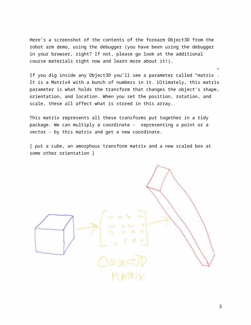
This matrix represents all these transforms put together in a tidy package. We can multiply a coordinate - representing a point or a vector - by this matrix and get a new coordinate.
[ put a cube, an amorphous transform matrix and a new scaled box at some other orientation ]
That’s honestly it in a nutshell: any object we make is ultimately represented by a bunch of points. These points are in the object’s own sort of space. For example, if we make a cube using CubeGeometry, it is centered around the origin. We transform the cube’s points by a transform matrix to move, rotate, and scale it as desired.
[ New drawing draw 4x4 matrix showing order of elements, in columns, n11, n12, n13, n14, n21, n22, n23, n24, n31, n32, n33, n34, n41, n42, n43, n44
SAVE PIECES OF DRAWING AS YOU GO, in separate layers: empty matrix, empty vector = matrix * vector, filled in of left and right vector only (for identity),filled of all three, without DNC at top or below. ]
3

A transform matrix is a 4 by 4 set of numbers. Three.js also supports a Matrix3 type, which almost no one uses. In math in general, a matrix can have any dimensions at all, such as 12 by 38. The 4 by 4 matrix is the size that the GPU prefers.
[ add D = N C to diagram - make sure to put arrows over vectors ]
4
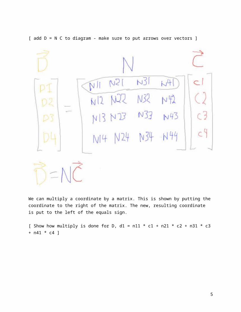
We can multiply a coordinate by a matrix. This is shown by putting the coordinate to the right of the matrix. The new, resulting coordinate is put to the left of the equals sign.
[ Show how multiply is done for D, d1 = n11 * c1 + n21 * c2 + n31 * c3 + n41 * c4 ]
5
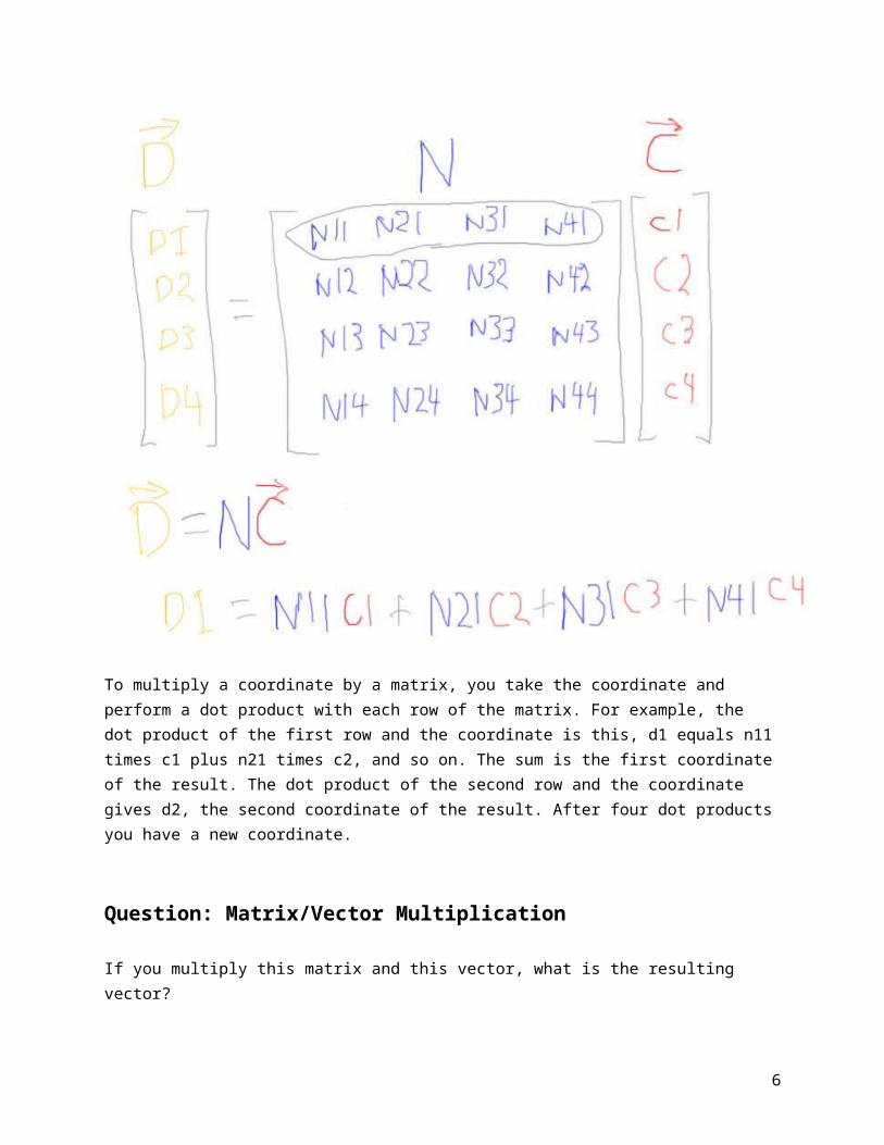
To multiply a coordinate by a matrix, you take the coordinate and perform a dot product with each row of the matrix. For example, the dot product of the first row and the coordinate is this, d1 equals n11 times c1 plus n21 times c2, and so on. The sum is the first coordinate of the result. The dot product of the second row and the coordinate gives d2, the second coordinate of the result. After four dot products you have a new coordinate.
Question: Matrix/Vector Multiplication
If you multiply this matrix and this vector, what is the resulting vector?
[ ___ ] [ 2 -1 3 5 ] [ 2 ][ ___ ] = [ 1 3 0 4 ] [ 0 ][ ___ ] [ 3 0 -1 -2 ] [ -1 ][ ___ ] [ 0 0 0 1 ] [ 1 ]
6

Answer
The answer is 6 6 5 1.
Lesson: Point and Vector Coordinates[ Start with vector matrix multiply diagram, or some portion thereof ]
Points and vectors are mathematical entities representing locations and movements. When we give them coordinates, we’re saying where they are or where they move in comparison to some frame of reference.
We use three coordinate values for both a point and a vector. We’ve been keeping track in our heads whether a coordinate represents a point or a vector. Up to this point you’ll notice for matrix multiplication our coordinates have four values.
---- [ new page ]
[ (x,y,z,1) is a point (x,y,z,0) is a vector ]
When using matrices, the way we tell points from vectors is by putting a 1 or 0 for the last coordinate. This also works rather nicely as an operation check when using point and vector math.
[ Make vectors in blue, points in yellow: green for good results, red for illegal(a,b,c,0) + (d,e,f,0) -> (a+d, b+e, c+f, 0+0) : 0, vector
7

(a,b,c,0) - (d,e,f,0) -> (a-d, b-e, c-f, 0-0) : 0, vector
(p,q,r,1) + (d,e,f,0) -> (p+d, q+e, r+f, 1+0) : 1, point
(p,q,r,1) - (s,t,u,1) -> (p-s, q-t, r-u, 1-1) : 0, vector
(p,q,r,1) + (s,t,u,1) -> (p+s, q+t, r+u, 1+1) : 2, illegal!]
If we add two vectors, the fourth coordinates add up to be 0, which means a vector. Same thing happens with subtracting one vector from another.
If we add a point and a vector, we get a point, just as we’d expect.
If we subtract one point from another, we get a vector, showing the movement needed to go from the second point to the first.
This fourth coordinate also acts as a way to check against doing illegal things. If you add two points, this normally has no real meaning. The fourth coordinate is 2, which is a tipoff that something is not right.
Now that we have this fourth coordinate, we can multiply points and vectors by a 4 by 4 matrix.
[ Additional course materials: the Chrome debugger is described here http://developer.chrome.com/extensions/tut_debugging.html, Firefox’s Firebug debugger here http://getfirebug.com/javascript, Safari here http://petewarden.typepad.com/searchbrowser/2008/07/how-to-debug-ja.html and then here http://developer.apple.com/library/safari/#documentation/appleapplications/Conceptual/Safari_Developer_Guide/DebuggingYourWebsite/DebuggingYourWebsite.html#//apple_ref/doc/uid/TP40007874-CH8-SW1 ]
Lesson: Identity Matrix[ Draw identity matrix, then add in multiplication framework of vectors. Show generic vector c1 c2 c3 c4. Note that at end D == C. Draw a little geometric diagram of an origin-centered square. ]
8
The usual default setting for a matrix is what is called the identity matrix. It consists of 0’s everywhere except along the diagonal, which is set to 1’s.
If you multiply any coordinate by this matrix, you’ll get exactly the same coordinate back out. The first row of the matrix selects the first coordinate out of the coordinate array, the second row selects the second coordinate, and so on. Try it yourself.
[ show on screen:
9

]
In three.js we create a Matrix4 by this bit of code, as usual.
var mtx = new THREE.Matrix4();
By default this matrix is the identity matrix.
[ show on screen:
]
If during processing we want to reset a Matrix4 to identity, we call the identity method on the class.
mtx.identity();
Lesson: Translation Matrix[ Draw translation matrix, then add in multiplication framework of vectors. Show a vector getting multiplied. Note T is the translation position desired. Draw a little geometric diagram. ]
10
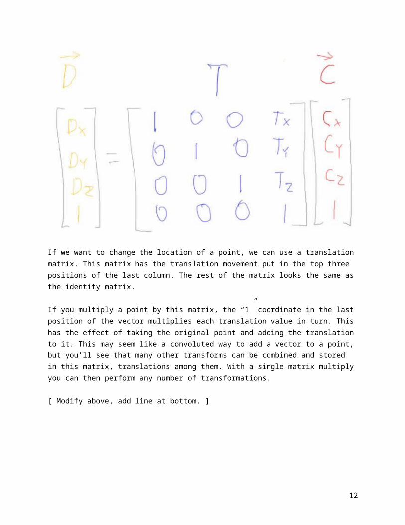
If we want to change the location of a point, we can use a translation matrix. This matrix has the translation movement put in the top three positions of the last column. The rest of the matrix looks the same as the identity matrix.
If you multiply a point by this matrix, the “1” coordinate in the last position of the vector multiplies each translation value in turn. This has the effect of taking the original point and adding the translation to it. This may seem like a convoluted way to add a vector to a point, but you’ll see that many other transforms can be combined and stored in this matrix, translations among them. With a single matrix multiply you can then perform any number of transformations.
[ Modify above, add line at bottom. ]
11
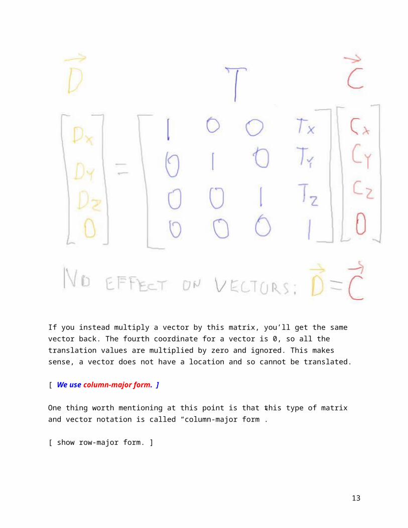
If you instead multiply a vector by this matrix, you’ll get the same vector back. The fourth coordinate for a vector is 0, so all the translation values are multiplied by zero and ignored. This makes sense, a vector does not have a location and so cannot be translated.
[ We use column-major form. ]
One thing worth mentioning at this point is that this type of matrix and vector notation is called “column-major form”.
[ show row-major form. ]
12
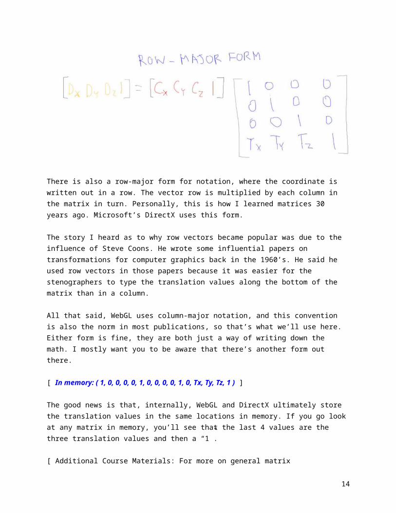
There is also a row-major form for notation, where the coordinate is written out in a row. The vector row is multiplied by each column in the matrix in turn. Personally, this is how I learned matrices 30 years ago. Microsoft’s DirectX uses this form.
The story I heard as to why row vectors became popular was due to the influence of Steve Coons. He wrote some influential papers on transformations for computer graphics back in the 1960’s. He said he used row vectors in those papers because it was easier for the stenographers to type the translation values along the bottom of the matrix than in a column.
All that said, WebGL uses column-major notation, and this convention is also the norm in most publications, so that’s what we’ll use here. Either form is fine, they are both just a way of writing down the math. I mostly want you to be aware that there’s another form out there.
[ In memory: ( 1, 0, 0, 0, 0, 1, 0, 0, 0, 0, 1, 0, Tx, Ty, Tz, 1 ) ]
The good news is that, internally, WebGL and DirectX ultimately store the translation values in the same locations in memory. If you go look at any matrix in memory, you’ll see that the last 4 values are the three translation values and then a “1”.
[ Additional Course Materials: For more on general matrix multiplication and the basics of linear algebra, see http://betterexplained.com/articles/linear-algebra-guide/ .
A discussion of row-major vs. column major form in computer graphics is here, http://steve.hollasch.net/cgindex/math/matrix/column-vec.html. It also discusses left-handed vs. right-handed, another source of conflict. ]
Question: Make a Translation Matrix
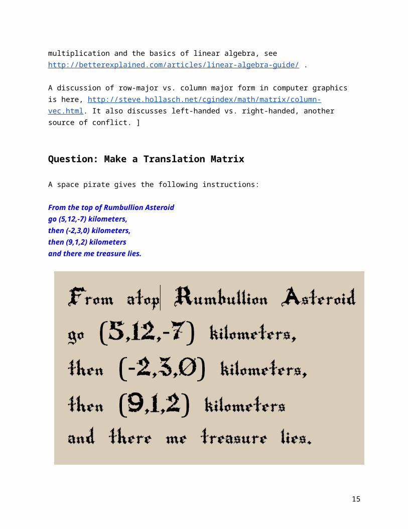
A space pirate gives the following instructions:
13
From the top of Rumbullion Asteroidgo (5,12,-7) kilometers,then (-2,3,0) kilometers,then (9,1,2) kilometersand there me treasure lies.
You don’t have all day, you want to send your cargo droid there directly to get the loot. Your droid uses a matrix to determine what orientation and position you’d like it to achieve. What translation matrix do you give it?
Matrix is: 1 0 0 ___ 0 1 0 ___ 0 0 1 ___ 0 0 0 1
AnswerTranslations can be added together to give a single translation vector. So, we add up the three vectors, to get the answer 12, 16, -5.
14
Lesson: Using a Matrix
To set a Matrix4 on creation, you can pass the values for the matrix in the constructor function.
var mtx = new THREE.Matrix4(1, 0, 0, 12, 0, 1, 0, 16, 0, 0, 1, -5, 0, 0, 0, 1 );
These values set the matrix to perform translation, moving an object to position 12, 16, -5. Note that this initialization is purposely made to look like column-major form, where the translation values are on the right. However, this order is NOT how the data is stored in the matrix itself.
15

If you looked at say mtx.elements[3], that looks like it might be the 4th number in the list, a 12. In fact, you’ll be looking at a 0 from the lower left corner of the matrix.
with the translation at the end, where expected.
[
]
Since translation is a common transform, three.js provides a function to set a translation, called makeTranslation. You give the position and it fills in the matrix for you.
To apply a Matrix4 to an Object3D, the most direct way of doing so is to set the local matrix on the object itself. However, you also need to set matrixAutoUpdate to false. This tells three.js to turn off its position, rotation, scale system and ignore those parameters, leaving alone whatever you have put in the matrix yourself.
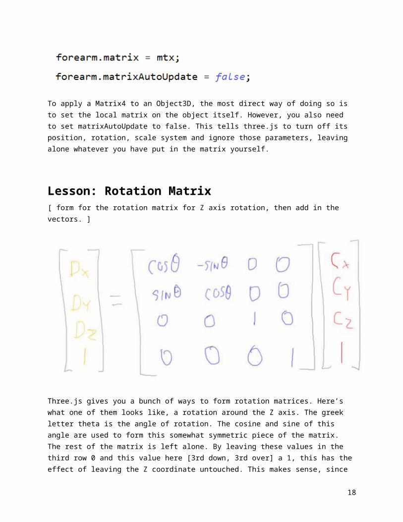
Lesson: Rotation Matrix[ form for the rotation matrix for Z axis rotation, then add in the vectors. ]
16

Three.js gives you a bunch of ways to form rotation matrices. Here’s what one of them looks like, a rotation around the Z axis. The greek letter theta is the angle of rotation. The cosine and sine of this angle are used to form this somewhat symmetric piece of the matrix. The rest of the matrix is left alone. By leaving these values in the third row 0 and this value here [3rd down, 3rd over] a 1, this has the effect of leaving the Z coordinate untouched. This makes sense, since when you rotate around the Z axis the Z values shouldn’t change.
[ show a sample rotation, real numbers like 0.6, 0.8 for 53.1, my favorite angle. Show the two axes, which should be in the positive X half of the thing, in a second separate graph, in red. ][ USE A GRID UNDERLAY and RULER TO GET THE NUMBERS RIGHT! ]
Here’s a real rotation matrix around the Z axis, for a rotation angle of 53.1 degrees. As an example, the coordinate (1,0,0) transforms to the coordinate (0.6,0.8,0). The coordinate is rotated counterclockwise around the origin.
What’s interesting about these numbers here in the upper left is that they describe two axes. This first, X axis is formed by these two coordinates (top two), and so is in this lower quadrant. This second, Y axis uses the other two and is in this upper quadrant. Notice that these axes are rotated clockwise by 53.1 degrees.
17
The rotation transformation can also be thought of as taking our original point and looking up what value it has on these two new axes. For example, on our new X axis the point’s coordinate is 0.6. On our new Y axis the point’s coordinate is 0.8.
On the left we’re rotating the coordinate with respect to the axes. On the right we’re rotating the axes and then seeing where the coordinate lies with respect to these new axes. Either interpretation is correct, and both have their strengths.
[ rotate drawing on left to have same orientation as second, not vice versa ]
If we rotate the first interpretation so that the X and Y axes align with the second, we see that the transformed point is in the same orientation to the axes in both cases.
This second interpretation is the one that helped me understand how a dot product is rotating a point. In an earlier lesson we talked about how the dot product between two normalized vectors gives us the cosine of the angle between them. Rotation is a similar use of the dot product: we used the cosine of the rotation angle to give us two new axes, both of which are normalized - that is, their lengths are both 1. The dot product between our test point’s coordinates and each rotation axis gives us a coordinate of the new point location. A dot product projects one vector onto another, which is what gives us these coordinates.
18

[ add a second point ]
This was a simple case, where the vector to our test point was of length one. If we do the same analysis for another point, we get the same result with both ways of thinking. On the left, we read the point’s coordinates from the original axes after rotating it. On the right, we rotate the axes and read the point’s coordinates with respect to these axes.
The way we “read off” these coordinates is to take a dot product between each axis and the vector to the point. This is what a matrix does, computes a dot product. When we used the dot product for materials, both vectors were normalized. Here, our axis is normalized but the vector to the point is not - that vector can be of any length.
[ below show full dot product explanation: dot( A, B ) vectors that are unnormalized gives length A times length B times cos of angle ]
19

Here is the meaning for the dot product of two arbitrary coordinates. With an unnormalized vector, like this second point’s vector, when you compute the dot product with an axis you get the usual cosine of the angle, multiplied by the vector’s length.
[ add in bold, big, BASIS ]
20

To sum up, you can think of a coordinate as moving due to rotation, or staying still and just being recategorized by a new set of axes. These three axes as a set are called a Basis.
Question: Axis of Rotation
[ axis/angle rotation
mtx.makeRotationAxis( axis, theta );
cube and show diagonals and coordinates]
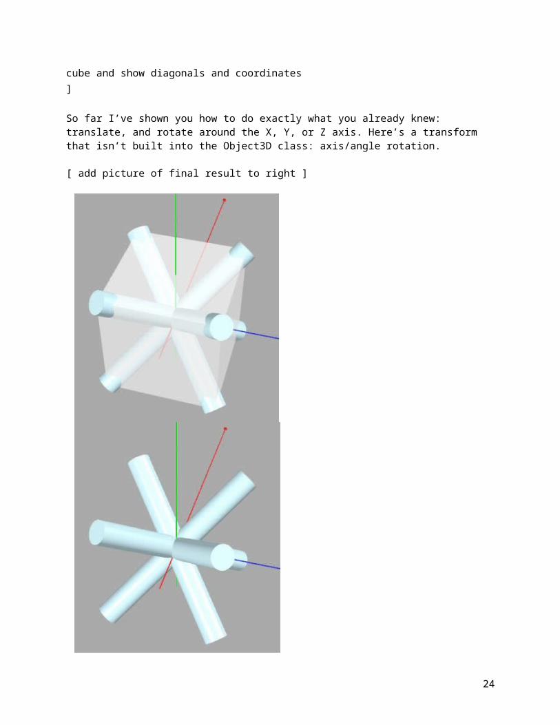
So far I’ve shown you how to do exactly what you already knew: translate, and rotate around the X, Y, or Z axis. Here’s a transform that isn’t built into the Object3D class: axis/angle rotation.
[ add picture of final result to right ]
21

Say I want to make a little star-shaped ornament out of four cylinders. Or, if you’re feeling more dramatic, I want to make some carbon-fiber caltrops to trip up the robo-minotaurs about to launch a final assault on our base on Centisi Prime, it’s really our last hope.
I want to align the four cylinders with the four diagonals of a cube. The hard part is figuring out the rotation matrix I want to use, if I’m stuck using Euler angles. Do I rotate in Y and then X, or Z and then Y, or something else?
With the axis/angle function I need to figure out what axis I want to rotate around, and how much to rotate.
22

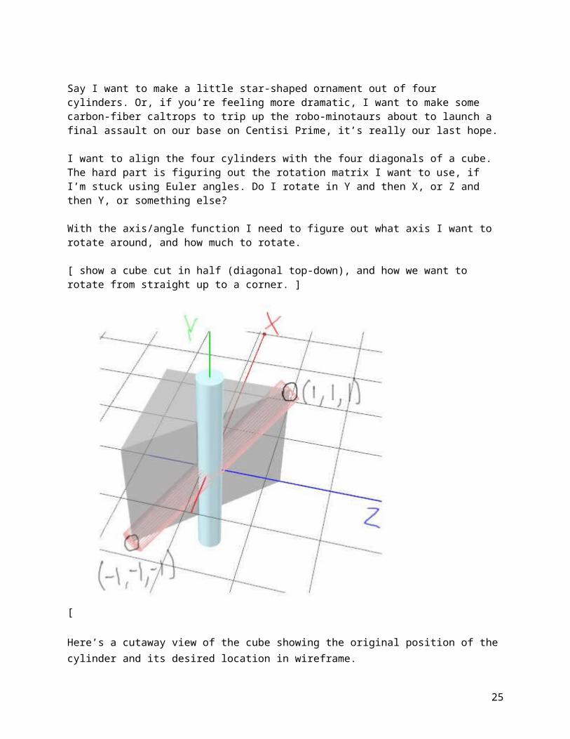
[ show a cube cut in half (diagonal top-down), and how we want to rotate from straight up to a corner. ]
[
Here’s a cutaway view of the cube showing the original position of the cylinder and its desired location in wireframe.
Every cylinder starts pointing up along the Y axis. Step one is to figure out around which axis to rotate this vertical cylinder. I want to rotate the cylinder to the point X,Y,Z all equal to 1. Which axis do I want to rotate around in order to get the cylinder to this final position?
[ Draw the axis answer, then say it, for each axis ]
23
[ ] Axis 1, which goes along the Y axis.[ ] Axis 2, which goes along this negative X, Z axis.[ ] Axis 3, which goes along this X,Y,Z axis itself.[ ] Axis 4, which goes along the Z axis.
Mark each that is correct, if any.
My advice is to think back to the rotation question earlier on, as it might help you out.
Answer
[ Show a view of the cube, draw the line continuing around to form a circle..]
[ probably label X Y and Z again, to help.
24
This can be a hard problem to think about - I got the axis wrong myself when I was first making up this quiz! Drawing sketches helps.
Remember that a vector rotating around an axis forms a circle. The cylinder’s axis on the Y axis and the final axis through the corner of the cube form define a circle whose center is at the origin. If you think about continuing this arc around the whole way, it becomes pretty clear that you’re cutting the cube in half diagonally, when viewed from above. We can also see that the axis through this circle is going to point in this direction or the opposite direction in order to be perpendicular to this slice. Since the Y axis is in this slicing plane, there won’t be any Y component in the coordinates for the axis of rotation itself. So, this axis must be either X=1 and Z=-1 or X=-1 and Z=1. This second answer matches what we’ve found, so is the correct one.
There can only be one plane that contains the circle, and there is only one axis direction, or its opposite direction, that is perpendicular to this plane. Therefore, there is only one axis of rotation that will take us from our starting position to the corner of the cube, so we can rule out
25

the other answers.
Lesson: Angle of Rotation
[ write axis of rotation: -1, 0, 1 - need to normalize itangle of rotation: unknownlength of cylinder: unknown
]
I have my axis of rotation, it’s -1, 0, 1.
If I look at my cube, it’s pretty easy to figure out the diagonal directions themselves. Here’s the easiest one: it goes from -1,-1,-1 to 1,1,1, so the cylinder’s axis is 2,2,2. We can also use this vector’s length to find the distance from one corner to another.
// get two diagonally-opposite corners of the cube and compute the// cylinder axis direction and lengthvar maxCorner = new THREE.Vector3( 1, 1, 1 );var minCorner = new THREE.Vector3( -1,-1,-1 );
26

var cylAxis = new THREE.Vector3();cylAxis.subVectors( maxCorner, minCorner );var cylLength = cylAxis.length();
Here’s three.js code that does this. Three.js uses a class called Vector3, but what you put in a Vector3 - a point or a vector’s coordinates - is up to you. Perhaps a better name might have been Coordinate3, but that’s pretty bulky. Most graphics systems you’ll encounter will call coordinates “vectors”, but it’s easy enough to understand from the context what is meant.
To find the cylinder’s axis direction and length, I set up the two corner locations. I then subtract one vector from another using the subVectors method, giving a vector from one point to another. There are a huge number of vector and matrix operations supported in three.js, subtraction is just one of many. Once we have the cylinder axis, this last line of code computes the length of this axis, which we’ll need for knowing how long to make the cylinder.
// take dot product of cylAxis and up vector to get cosine of anglecylAxis.normalize();var theta = Math.acos( cylAxis.dot( new THREE.Vector3(0,1,0) ) );
We now have what we need to figure out the angle between the Y axis, where our cylinder starts, and the corner of the cube. The dot product computes the cosine of the angle between two normalized vectors. So we normalize the cylinder axis and take its dot product with the Y axis vector here. This gives us the cosine of the angle, so we take the arccosine and get the angle back, in radians.
cylAxis.normalize();var theta = Math.acos( cylAxis.y );
27

Using a dot product is a bit of overkill, by the way. Computing a dot product with the Y axis like this is the same as just grabbing the Y component of the cylAxis vector. We could have simply normalized and done this, like this code here. However, unless this is a critical loop, like we’re making a billion of these ornaments, I’d recommend using this first way. If someone reads or modifies the code in the future, the intent is clearer and more general.
Now we have all the facts we need to make this object, so let’s get cracking! Well, I guess I should mention that the sign of theta might be a little questionable. We could use the right-hand rule to make sure we have the direction of rotation right.
[ pro tip: reverse and try again ]
Or we could “reverse and try again”.
I learned about this practice long ago from an article in an old trade journal called “SGI Insider”. It was great to realize that someone else was doing what I also do: if I put in a rotation and it then goes the wrong direction, just try the opposite. So feel free to do the same, as you’re in good company. You could spend 15 minutes trying to figure out the sign needed after using some set of matrix operations, and still have about a 50% chance of getting it right. Faster and more reliable is to just try it and see.
That said, this practice won’t help much if there are too many things to negate, or the rotation is part of a long chain of transforms, or if you’re starting from an incorrect algorithm. But, if you’re feeling the math is solid, go ahead and do it.
[ show negative rotation, then correct one, then reversed axis ]
[ program is unit4-axis_angle_explain.js ]
28

axis of rotation: (-1,0,1), flip to (1, 0, -1)angle of rotation: -theta, flip to theta ]
Doing it here with my test program, I found I needed to negate the angle to move the rod to the correct place. I don’t really like negative angles, so I negated both the angle and the axis direction. This should give exactly the same rotation: if you rotate clockwise around one axis, rotating counterclockwise around the opposite axis direction is the same thing.
Lesson: Cross Product
[ show drawing above again, clean, this time label with two axes. SHOVE WAY TO LEFT! ]
29

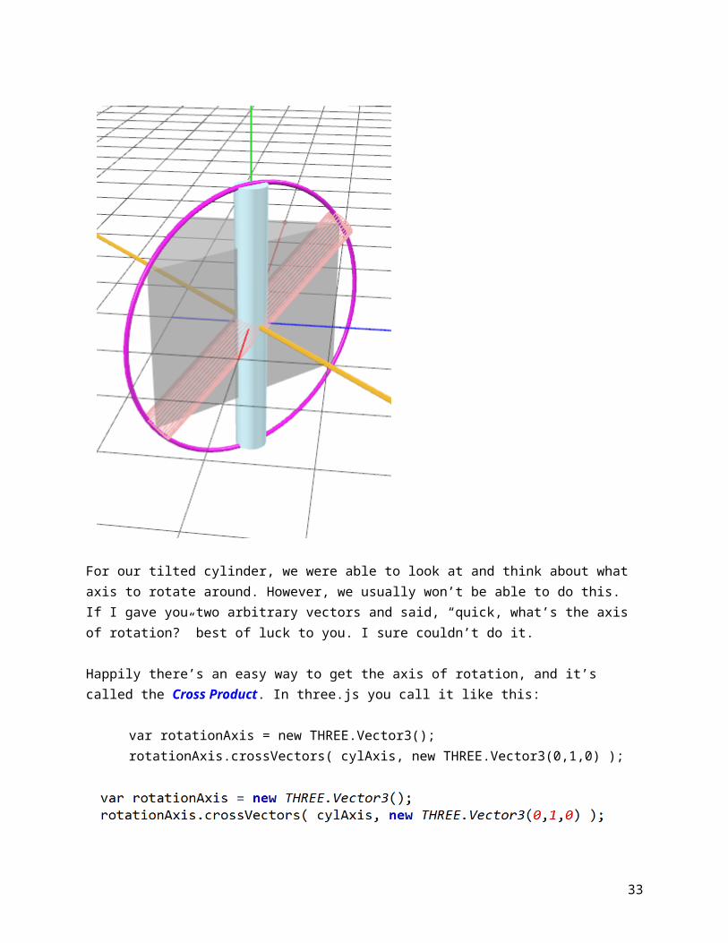
For our tilted cylinder, we were able to look at and think about what axis to rotate around. However, we usually won’t be able to do this. If I gave you two arbitrary vectors and said, “quick, what’s the axis of rotation?” best of luck to you. I sure couldn’t do it.
Happily there’s an easy way to get the axis of rotation, and it’s called the Cross Product. In three.js you call it like this:
var rotationAxis = new THREE.Vector3();rotationAxis.crossVectors( cylAxis, new THREE.Vector3(0,1,0) );
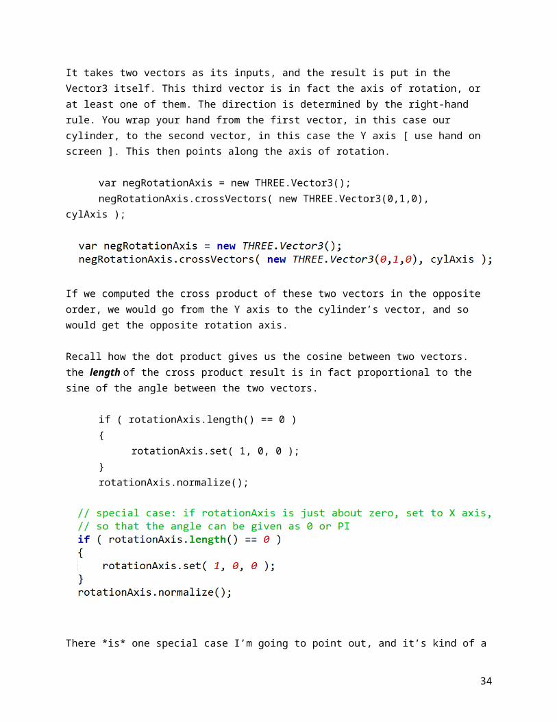
It takes two vectors as its inputs, and the result is put in the Vector3 itself. This third vector is in fact the axis of rotation, or at least one of them. The direction is determined by the right-hand rule. You wrap your hand from the first vector, in this case our cylinder, to the second vector, in this case the Y axis [ use hand on screen ]. This then points along the axis of rotation.
30

var negRotationAxis = new THREE.Vector3();negRotationAxis.crossVectors( new THREE.Vector3(0,1,0), cylAxis );
If we computed the cross product of these two vectors in the opposite order, we would go from the Y axis to the cylinder’s vector, and so would get the opposite rotation axis.
Recall how the dot product gives us the cosine between two vectors. the length of the cross product result is in fact proportional to the sine of the angle between the two vectors.
if ( rotationAxis.length() == 0 ){
rotationAxis.set( 1, 0, 0 );}rotationAxis.normalize();
There *is* one special case I’m going to point out, and it’s kind of a headache. If the cross product gives back a vector that is of length 0, or nearly so, then the two vectors are either pointing in the same or in directly opposite directions. You can use the dot product of the two vectors to figure out which. If they point in the same direction, then you’re done - you don’t need to rotate at all. If they point in exactly opposite directions, then you need to rotate 180 degrees.
[ 180 degrees → rotation axis 0,0,0 ]
However, this rotation axis is 0,0,0, which is no axis at all! At this point you basically need to choose some arbitrary axis that is perpendicular to your vectors and use that for rotation, or just form the rotation matrix directly. See the additional course materials on a good way to solve this problem.
[ put animation http://en.wikipedia.org/wiki/Cross_product ]
[ MARK AS VECTORS! A X B == sin theta * length( A) * length( B ) ]
31

A = Ax Ay AzB = Bx By Bz
A x B = … as shown above, Sarrus’ rule]
The cross product itself is computed by multiplying neighboring elements of the two vectors’ coordinates for the X coordinate. That is, Ax times By has Ay times Bx subtracted from it, Ay times Bz has Az times By subtracted from it, and then we wrap around the ends and Az times Bx has Bz times Ax subtracted from it.
[ Additional Course Materials: To understand the computations for the cross product, see http://en.wikipedia.org/wiki/Cross_product. The best paper I know on solving the 0-length vector problem is by Tomas Möller and John F. Hughes, “Efficiently Building a Matrix to Rotate One Vector to Another'', http://graphics.cs.brown.edu/~jfh/papers/Moller-EBA-1999/paper.pdf ]
Exercise: Make an Ornament/Caltrop
[axis of rotation: now 1, 0, -1 - need to normalize itangle of rotation: computed as thetalength of cylinder: computed as cylLength]
[italics: speak rapidly and sotto voce]To make our ornament or defensive device to stop the robo-minotaurs from destroying all things good and just we need to rotate each cylinder into position. We have all the data we need for the first cylinder.
var cylinder = new THREE.Mesh( new THREE.CylinderGeometry( 0.2, 0.2, cylLength, 32 ), cylinderMaterial );
var rotationAxis = new THREE.Vector3(1,0,-1);// makeRotationAxis wants its axis normalizedrotationAxis.normalize();// don’t use position, rotation, scalecylinder.matrixAutoUpdate = false;cylinder.matrix.makeRotationAxis( rotationAxis, theta );scene.add( cylinder );
32
For the axis/angle function we need to pass in a normalized axis and an angle in radians. This function could normalize the axis itself, just to be safe. However, for efficiency’s sake, it doesn’t, so we normalize the rotationAxis.
Next we do an obscure thing: set matrixAutoUpdate to false. This parameter is true by default. What it means is that, if true, then our Object3D’s matrix will be computed from its position, rotation, and scale parameters. By setting it to false, we tell three.js that we are not going to use these parameters but rather are going to set the matrix itself directly. And that’s exactly what we do in the next line, where we at long last finally call the makeRotationAxis method, giving it our normalized axis and angle.
[ initial view, final view ]
At long last we have added a cylinder at the proper angle and length to our scene. Now it’s your turn to finish off the rest. Add another three cylinders to complete the object.
33
[ Exercise code at http://www.realtimerendering.com/udacity/?load=unit5/unit5-axis_angle_exercise.js ]
[ Additional Course Materials: the axis/angle formula is discussed here http://www.gamedev.net/reference/articles/article1199.asp ]
Answer[ solution: *redacted* ]
[ Draw an X next to the var x var z stuff and label -X -Z etc. ]
// instancing: reuse the geometry four timesvar cylinderGeo = new THREE.CylinderGeometry( 0.2, 0.2, cylLength, 32 );for ( var i = 0; i < 4; i++ ){
var cylinder = new THREE.Mesh( cylinderGeo, cylinderMaterial );
var x = (i < 2) ? -1 : 1;var z = (i % 2) ? -1 : 1;var rotationAxis = new THREE.Vector3(x,0,z);rotationAxis.normalize();
34

cylinder.matrixAutoUpdate = false;cylinder.matrix.makeRotationAxis( rotationAxis, theta );
scene.add( cylinder );}
There are a few ways to solve this one. Here’s the approach I took. I knew that the cylinders were all the same length, so created just one. I then reused this cylindrical mesh to make each cylinder object. To get the four rotation axes, I realized these formed an X-shape. If I could enumerate all four directions in my loop, I’d be done. That’s what this tricksy code does. It gives me -X, -Z on the first iteration, -X, +Z on the next, and so on. I then normalize this axis and use it, as usual.
You could also solve this one by using just two rotation axes and flipping the sign of theta, rotating each pair of cylinders in opposite directions.
Lesson: Rotation times Rotation
[ list order of operations as RxRyRz O ]
One reason that we use 4 by 4 matrices to store transforms is that a single matrix can hold any number of transforms at once. As an example, consider Object3D’s rotation parameter. Here’s a snippet of code from the Euler angle demo. The airplane’s three rotation axes are each set.
35

Despite this means that the airplane is first rotated around its Z axis, then its Y axis, then X.
[ draw three matrices, n11 n21 etc. = a11 a21 a31 a41 times b11 etc]
Internally, a transform matrix is made for each rotation, then these are multiplied together. Matrix multiplication works like this. For each location in the resulting matrix, you take the corresponding row of the first matrix and the column of the second and perform a dot product between the two.
[ draw n24 getting created by correct row and column, and show final equation ]
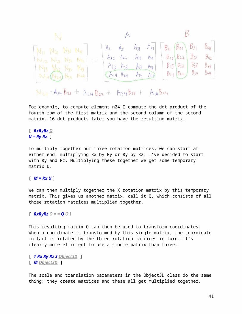
For example, to compute element n24 I compute the dot product of the fourth row of the first matrix and the second column of the second matrix. 16 dot products later you have the resulting matrix.
[ RxRyRz OU = Ry Rz ]
To multiply together our three rotation matrices, we can start at either end, multiplying Rx by Ry or Ry by Rz. I’ve decided to start with Ry and Rz. Multiplying these together we get some temporary matrix U.
[ M = Rx U ]
36

We can then multiply together the X rotation matrix by this temporary matrix. This gives us another matrix, call it Q, which consists of all three rotation matrices multiplied together.
[ RxRyRz O = = Q O ]
This resulting matrix Q can then be used to transform coordinates. When a coordinate is transformed by this single matrix, the coordinate in fact is rotated by the three rotation matrices in turn. It’s clearly more efficient to use a single matrix than three.
[ T Rx Ry Rz S Object3D ][ M Object3D ]
The scale and translation parameters in the Object3D class do the same thing: they create matrices and these all get multiplied together. Here’s the full sequence of transforms that happens for an Object3D when using its parameters. Internally the matrices are all multiplied together to give a single resulting matrix M. The parameter in the Object3D class is in fact called “matrix”.
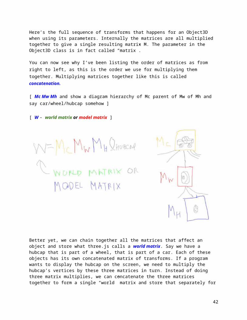
You can now see why I’ve been listing the order of matrices as from right to left, as this is the order we use for multiplying them together. Multiplying matrices together like this is called concatenation.
[ Mc Mw Mh and show a diagram hierarchy of Mc parent of Mw of Mh and say car/wheel/hubcap somehow ]
[ W - world matrix or model matrix ]
37

Better yet, we can chain together all the matrices that affect an object and store what three.js calls a world matrix. Say we have a hubcap that is part of a wheel, that is part of a car. Each of these objects has its own concatenated matrix of transforms. If a program wants to display the hubcap on the screen, we need to multiply the hubcap’s vertices by these three matrices in turn. Instead of doing three matrix multiplies, we can concatenate the three matrices together to form a single “world” matrix and store that separately for the hubcap. This matrix is often called the model matrix. Whatever you call it, a single matrix multiply is then all that is needed to transform a vertex from its model space to world space directly.
[ Additional Course Materials: It is worth noting that you can set an object’s Euler rotation angles from a given arbitrary rotation matrix using three.js’s Object3D.setEulerFromRotationMatrix method. ]
Question: Series of OperationsI showed how three rotation matrices multiplied together gives a single new matrix. Interestingly enough, this resulting matrix M is in fact a rotation matrix itself. Any number of rotation matrices multiplied together always result in another rotation matrix. This rotation matrix will have a single specific axis and rotation angle.
My question to you:
Yes or No, () () can you multiply a series of translations together and get a single translation matrix?() () can you multiply a series of scales together and get a single scale matrix?
For example, say you apply a number of scales in a row to an object, If you multiply all these scale matrices together do you get a single scale matrix, or something else?
AnswerEach translation matrix represents a vector, a movement. We can move an object by vector after vector and at the end of it, the object will have changed its location, nothing more. So we know the resulting concatenated matrix is purely a translation matrix. So the answer is Yes.
With scaling, each scale operation changes the dimensions of the object. Scale does not actually move or rotate the object, so a series of scales will result in a scale matrix. So the answer here too is yes.
Lesson: Frames
38

[ drawing of F at origin. Show rotate then translate, moving the axes with it each time. ]
[ Green arrow and yellow text will get added later - showing all now ]
In previous lessons we’ve seen that the order of transforms for an object is usually rotate, then translate.
We start with the letter F at the origin. If we rotate it negative 45 degrees, we get a tilted F. We then translate it by 1 unit vertically, and it moves up. This we write out as TR, with the matrices applied in reverse order.
However, we’re now able to use matrices whichever way we want, so say we reverse the order.
If instead we first translate up a unit, then rotate, we get this, the notation RT. Clearly different, with T changing the origin we then rotate around.
[ R Of ]
Here’s another way to look at it. Say we first just rotate the F. We express this by the notation R Object F. We could add a translation matrix before or after the Rotation. If we add it before the R, this means we translate the object after the rotation and so move it with respect to the world. Whatever happened before this translation was applied is said and done, the object is in
39

whatever orientation that’s already been set. Ancient history. That’s this top case, as before.
If we put the T after the R, it says to apply the translation first, then everything is rotated around the origin. So far I haven’t said anything new.
But, another way to look at all this is that you’re changing the frame of reference by each of these transforms. Instead of rotating or translating the object, we can think about it as that we’re changing the frame of reference. By taking this upper path [from left to upper left to lower right] we can think of the transforms in these terms. First the rotation changes the frame of reference that any transforms to the right of it will use, then the translation moves the object with respect to this new frame of reference.
Any point in space is given some XYZ coordinate only with respect to something. We started off by thinking of this “something” as world space. But notice we’ve actually been making models in what we call model space and then transforming them to world space. For example, when we have a parent-child relationship, the child is oriented with respect to the parent, not the world.
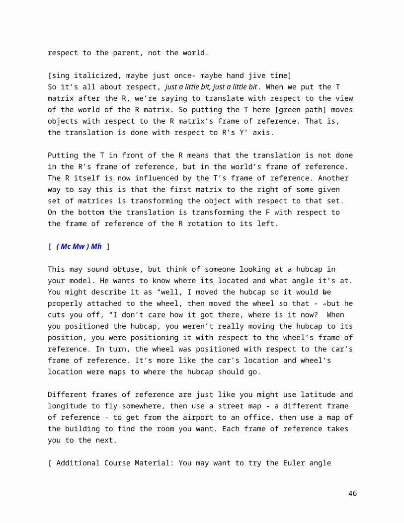
[sing italicized, maybe just once- maybe hand jive time]So it’s all about respect, just a little bit, just a little bit. When we put the T matrix after the R, we’re saying to translate with respect to the view of the world of the R matrix. So putting the T here [green path] moves objects with respect to the R matrix’s frame of reference. That is, the translation is done with respect to R’s Y’ axis.
Putting the T in front of the R means that the translation is not done in the R’s frame of reference, but in the world’s frame of reference. The R itself is now influenced by the T’s frame of reference. Another way to say this is that the first matrix to the right of some given set of matrices is transforming the object with respect to that set. On the bottom the translation is transforming the F with respect to the frame of reference of the R rotation to its left.
[ ( Mc Mw ) Mh ]
This may sound obtuse, but think of someone looking at a hubcap in your model. He wants to know where its located and what angle it’s at. You might describe it as “well, I moved the hubcap so it would be properly attached to the wheel, then moved the wheel so that -” but he cuts you off, “I don’t care how it got there, where is it now?” When you positioned the hubcap, you weren’t really moving the hubcap to its position, you were positioning it with respect to the wheel’s frame of reference. In turn, the wheel was positioned with respect to the car’s frame of reference. It’s more like the car’s location and wheel’s location were maps to where the hubcap should go.
Different frames of reference are just like you might use latitude and longitude to fly somewhere, then use a street map - a different frame of reference - to get from the airport to an office, then use a map of the building to find the room you want. Each frame of reference takes you to the next.
40
[ Additional Course Material: You may want to try the Euler angle demonstration program again, http://www.realtimerendering.com/udacity/?load=demo/unit4-euler_angles.js, as you can see how the X rotation controls the other two rotations, since it is applied last. ]
Lesson: Scale Matrix and Normals
[ show scale matrix form, Sx, Sy, Sz down diagonal ]
Here’s what a scaling matrix looks like. Set all three values to 1 and you get the identity matrix.If you want to uniformly scale something to be three times as large as before, set Sx, Sy, and Sz all to be 3. If you want to instead just stretch something up along the Y axis so it’s five times as tall, set Sx and Sz to 1 and Sy to 5.
There’s just one funny thing that happens with scaling in particular: it can mess up normals. Remember, we’re not just transforming points with matrices, we’re also transforming shading normals. If you run normals through a translation matrix, nothing happens to them, they’re vectors. If you run normals through a rotation matrix, things are fine.
[ line segment with normal, then scaled. ]
41
Here’s a triangle from a side view, looking along its plane, along with its normal. If you uniformly scale this object to be larger, look what happens. The object grows larger, as does the normal. The good news is that the normal doesn’t change direction, so all we have to do is renormalize it before using it in any lighting equations.
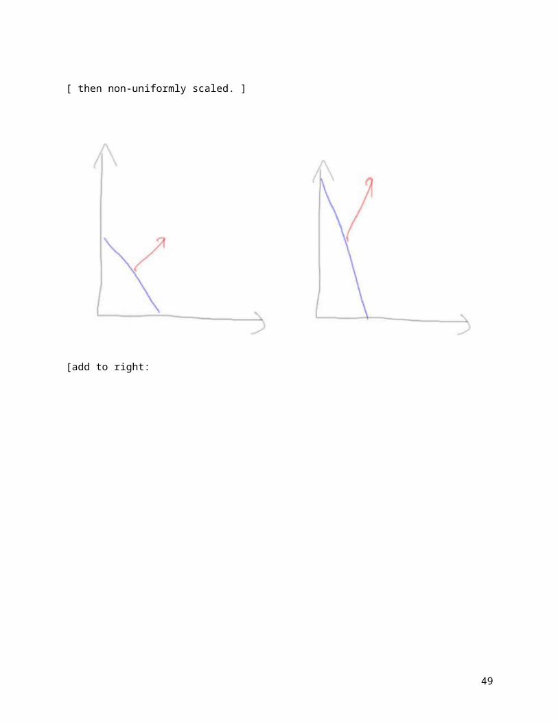
[ then non-uniformly scaled. ]
42

[add to right:
43

If you non-uniformly scale an object, in other words stretch or squish it, things get weird. Here I’ve stretch the triangle in one direction. The normal vector has also stretched upwards, and is clearly no longer pointing in the right direction. To solve this problem we’ll need to invert and transpose a matrix.
Lesson: Matrix Transpose and Inverse
44

First things first. The transpose of a matrix is this original matrix with its rows and columns flipped along the diagonal. There are two diagonals, but the one I mean is from upper left to lower right. It’s where we put scale factors, for example.
The other operation that is commonly done to a matrix is computing its inverse. If you multiply a matrix by its inverse, you get the identity matrix. The inverse of a matrix essentially undoes the work of that matrix. For example, if your matrix moves an object 5 units up, the inverse moves it 5 units down. The inverse of a rotation matrix is one that rotates on the same axis but back the other direction. The inverse of a scale matrix scales the object back down.
45
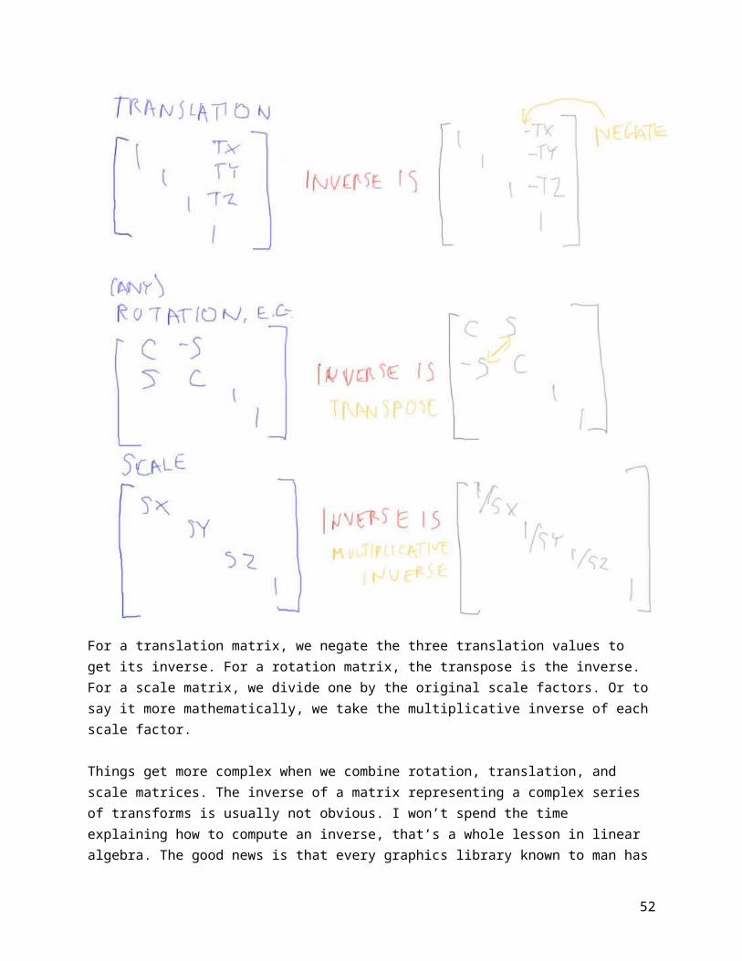
For a translation matrix, we negate the three translation values to get its inverse. For a rotation matrix, the transpose is the inverse. For a scale matrix, we divide one by the original scale factors. Or to say it more mathematically, we take the multiplicative inverse of each scale factor.
Things get more complex when we combine rotation, translation, and scale matrices. The inverse of a matrix representing a complex series of transforms is usually not obvious. I won’t spend the time explaining how to compute an inverse, that’s a whole lesson in linear algebra. The good news is that every graphics library known to man has a matrix inversion routine of some sort. Three.js is no exception, the Matrix4 class has a getInverse function.
46

Lesson: Correct Normal Transformation
We have a problem with transforming normals when using non-uniform scaling matrices. If we tried to transform the normal with the same scaling matrix used for transforming vertex coordinates, we ran into the strange situation of normals getting bent away from their surfaces.
[ Add text at bottom:
normal transform: transpose of the inverse or inverse of the transpose]
How to solve this? I’ll jump to the punchline. What you want to use to transform normals is the transpose of the inverse of the model matrix, or the inverse of the transpose. That’s a mouthful.
[ add each rule as needed ]
47

I’ll explain. First of all, forget about translation matrices. We are going to be transforming normals, and translation matrices do not affect vectors in any way. For normals we’ll really only need to invert the upper left 3x3 part of the matrix.
[ add rule for rotation ]
For rotation matrices the transpose is the inverse.
So for rotations the transpose of the inverse is the inverse of the inverse. This is starting to
48
sound like Alice in Wonderland! To be a little more clear, if you take the transpose of the inverse of a rotation matrix, you get the same rotation matrix back.
This means that for a matrix made up of any series of translations and rotations, you can use this same matrix to transform points and normals. This is because the transpose is the inverse, as far as normals are concerned.
[ add rules for scaling ]
Scaling makes it no longer true that the transpose is the inverse, so we have to take special steps. If the scaling matrix is uniform, in other words the shape of the object does not change, we can get away with just normalizing the normals after transforming by the original model matrix. For non-uniform scaling, where the shape of the object is changed, we must explicitly compute this special inverse of the transpose matrix in order to transform normals correctly. I’m not going to explain here why the transpose of the inverse works, you likely don’t want me to talk about contravariant and covariant vectors. See the additional course materials for more information.
If you keep away from non-uniform scaling matrices, you’ll never run into this mismatch and can merrily use the modeling matrix for both position and vector transforms. If you never use scales of any sort, you won’t even have to renormalize your vectors.
The good news is that if you use scales of any sort in three.js, it will correctly handle normal transformation for you. It’s only when you’re using scales on your own that you can get pretty weird shading results if you don’t pay attention.
[ old man voice ]I’ve seen many a young programmer led astray by normal transformation. Seriously, back in the 1980’s, before any book ever mentioned it, this problem was fairly common. Back then we consulted for a hardware company, writing programs using their expensive graphics accelerator. And I mean expensive, something like $35,000, the price of a nice BMW. I found that their graphics accelerator had this problem with polygon display, meaning we had to avoid using non-uniform scales as a modeling operation. They were more than a bit dismayed when they found out about this problem, since it’s costly to fix properly.
[ Additional Course Materials: Writing about this problem was about my first article for the internet, back in 1987: http://tog.acm.org/resources/RTNews/html/rtnews1a.html#art4.
Inverses and transposes are part of the field of linear algebra. If you have a interest in the subject, you might consider taking the Khan Academy’s course, http://www.khanacademy.org/math/linear-algebra. For a book specific to computer graphics, I like Farin and Hansford’s book “Practical Linear Algebra” http://www.amazon.com/exec/obidos/tg/detail/-/1568812345?tag=realtimerenderin - it builds up intuition through numerous figures throughout, and has a light but solid touch. For a derivation
49

of why the inverse transpose is used, along with much other useful math, see Lengyel’s “Mathematics for 3D Game Programming and Computer Graphics” http://www.amazon.com/gp/product/1435458869?tag=realtimerenderin ]
Lesson: Mirror Matrices[ put mirror matrix for Z ]
Draw a simple triangle and show it mirrored through Z axis (which should be up).
alice.scale.z = -1;
50

One transform matrix worth a quick mention is the mirror matrix, also called the reflection matrix. The one I show here switches the Z coordinate. The z-axis acts something like a mirror: anything on one side of the axis mirrored to the other.
You can create a mirror matrix easily enough in three.js by setting a scale value to negative 1. There are in fact an infinite number of mirroring matrices, since by rotation and translation you can move the mirroring plane.
[ draw a triangle on one side of Z axis and the other ]
51
One major problem with the mirroring matrix is that it not only flips the triangle, it also flips the sense of the triangle. Using a mirroring matrix converts from a right-handed coordinate system to a left-handed one, or vice versa. That is, in a right-handed system a triangle’s vertices normally proceed counterclockwise around its edge. After a mirror matrix this ordering is reversed. If you’re using backface culling, you have to reverse the culling sense from making the front side visible to the back side visible.
Even with this, I find that mirroring matrices are tricky to use in three.js. By default the reversal also affects lighting, for example, making it look like lights are coming from the opposite direction.
One place where mirroring sometimes is used is when modeling. Instead of sculpting a whole face, for example, you could make half a face. You then use a mirroring matrix to create the other half.
Sometimes you might encounter a matrix in a data file and don’t know where it came from. You can use the Matrix4 determinant call to see if there’s any mirroring in the matrix. If the determinant is negative, it contains a mirror.
[ Experiment at original-framework/unit4-mirror_solution.js - not for release ]
52

Question: Mirror Normal TransformationWe had to take corrective action when we transformed normals by a scale matrix, needing the inverse-transpose. For rotation and translation we could use the same matrix for normals that we used for points.
What happens to normals if they are transformed by the same mirroring matrix used for transforming points?
( ) The transform works only if the normal is perpendicular to the mirror’s surface.( ) The transform works only if the normal is parallel to the mirror’s surface.( ) The transform always works, but you must normalize the normal after.( ) The transform always works.
AnswerI won’t formally prove it here, but this transform always works. The intuitive explanation is that a mirroring matrix is like a uniform scaling matrix, so the same matrix can be used for transforming both points and lines. However, since no scaling is actually occurring, we don’t need to renomalize the normal. Therefore, this fourth answer is correct.
Lesson: Matrix Zones[ map of rotation, scale / translation / always 0 0 0 1 ; show coordinate multiplying it ]
53

Once you start looking under the hood you’ll get some sense of the lay of the land with matrices. Here’s a map of the sorts of things you’ll find.
[ linear transformation ]
The upper left area is where the rotations and scales show up. If a transform changes only this area of the matrix, it is called a linear transformation. I’m not going to spend time on the formal definition of this term; the additional course materials include resources for more on the underlying math. The definition is fairly basic stuff about how addition and multiplication are preserved, but doesn’t have much effect on how we do computer graphics.
The upper right is where translations accumulate. These translation values will get affected by multiplication with other matrices, of course. Translations only affect points, since vectors have a zero for their fourth coordinate.
[ mtx.decompose( t, r, s ) - r is a quaternion ]
Three.js provides a function to extract the translation, rotation, and scale components from a matrix. The translation and scale factors come back as vectors, as you might expect. The rotation comes back as a quaternion, something we’ll talk about when we get to animation. The short version is that a quaternion is a compact way to store the axis and angle of rotation for a rotation matrix. One useful property quaternions have is that you can easily interpolate between them, which is useful for interpolating between two different orientations.
[ affine transform ]
Notice that the bottom row is always 0 0 0 1. The transforms we’ve covered here are called affine transforms. Parallel lines stay parallel when an affine transform is applied. In modeling you’ll essentially always use affine transforms, so will never change this last row. Since GPUs are tuned to use 4x4 matrices, most of us just use 4x4’s everywhere for simplicity’s sake.
[ projective transform ]
When we discuss perspective cameras, we will set the values in this last row - we’ll then be using projective transforms. With affine transforms, when a point’s coordinates are multiplied by the matrix, the fourth coordinate starts out as 1 and ends up as 1. This last row in a projection matrix modifies that fourth coordinate to be something other than one. What that means is something we’ll leave until a later lesson.
[ WebGL and three.js matrices are in column order
TRS TRS O - apply matrices to objects from right to left. (TR)S == T(RS) - matrices are associative
54

TR != RT - matrices are not (usually) commutative]
To sum up, with column-order matrices we record the transforms to the object from right to left. Matrices themselves are associative, you can multiply whichever two neighboring matrices you want in whatever order you want. Matrices are not commutative, that is, matrix order matters!
Now that you know a lot about transforms, I recommend poking around in the documentation and reading through all the functions available for vectors, matrices. More important still, go try them out. Take a three.js program of any sort and mess with it, change things and see what happens. Having JavaScript, an interpreted language with a built-in debugger, makes it easy to dig in and see what all sorts of programs are doing.
[ Additional Course Materials: A nice demo showing how rotation and translation affect the various parts of the matrix is at http://voxelent.com/html/beginners-guide/1727_04/ch4_ModelView.html. This is from the book “WebGL Beginner’s Guide”, which is good for getting into the nitty gritty of WebGL itself. http://www.amazon.com/WebGL-Beginners-Guide-ebook/dp/B008CEMBPI/ - the eBook version is particularly affordable.
Khan Academy discusses what a linear transformation is, along with much other linear algebra: https://www.khanacademy.org/math/linear-algebra/matrix_transformations/linear_transformations/v/linear-transformations. There are many books that discuss linear algebra and its use in computer graphics, such as http://www.amazon.com/exec/obidos/tg/detail/-/1568812345?tag=realtimerenderin, Gortler’s Fundamentals, Lengyel’s, ours, maybe Angel’s. ]
Lesson: Wrap-Up
[ http://mrdoob.github.com/three.js/examples/webgl_materials.html ]
You've just finished working through one of the most difficult areas of interactive 3D graphics. Between transforms and materials, you've learned two critical elements of the field. You can now create and display 3D objects in your own virtual worlds.
I think of this point in the course as the top of the roller-coaster ride. With these basics down, we can now explore areas that will let you create even richer scenes and applications.
[ Additional Course Materials: Lee Stemkoski’s example programs of how to do various operations in three.js are a great resource http://stemkoski.github.com/Three.js/index.html . ]
55

Problem Set
Problem 5.1: Transpose of a Translation
The transpose of a rotation matrix is its inverse, the rotation goes in the opposite direction. What sort of matrix is the transpose of a translation matrix?
[ ] It is a quaternion[ ] It is a linear matrix[ ] It is an affine matrix[ ] It is a projective matrix
Check all that apply.
AnswerThis matrix is not a quaternion. No matrix is a quaternion, not even a rotation matrix. A rotation transform can be represented by a rotation matrix. A quaternion is an alternate representation for a rotation transform.
The transpose of a translation matrix puts its translation values in the bottom row of the matrix. The only type of matrix that puts values in this area is a projective matrix. So of these three types of matrices, the only correct one is “projective matrix”. To be honest, I don’t know what sort of projection it would do - it’s not one that we normally run into in computer graphics - but it definitely is a projection of some sort.
Problem 5.2: Matrix Spotting
[ Translation[ Rotation[ Rotation & Translation[ Scale
< Put these in a different order >
[ 1 0 0 5 ][ 0 1 0 -2 ][ 0 0 1 0 ][ 0 0 0 1 ]
[ 0 -1 0 0 ]
56

[ 1 0 0 0 ][ 0 0 1 0 ][ 0 0 0 1 ]
[ 0.8 0 -0.6 5 ][ 0 1 0 -2 ][ 0.6 0 0.8 0 ][ 0 0 0 1 ]
[ 4 0 0 0 ][ 0 3 0 0 ][ 0 0 2 0 ][ 0 0 0 1 ]
Answer
This matrix is a translation matrix, because only this fourth column is different than the identity matrix. These values are the translation amounts.
This matrix is a rotation matrix, because the upper left 3x3 has been modified, and not in a simple way like a scaling matrix. I should mention that if the 3x3 area is changed in an arbitrary way, you can get what is called a “shear” matrix. I see shear matrices get mentioned in textbooks - hey, we cover them in our own book! - but personally in the past three decades I never ever have used one.
This matrix has elements of both translation and rotation, and so it is the two of these types multiplied together.
This leaves this last matrix as a scaling matrix. It is non-uniformly scaling along each axis.
Problem 5.3: Cylinder Positioning
57

[ canonical objects ]
Three.js tends to create what are called canonical objects. This is where you create an object centered around the origin and then apply a series of transforms to move it into position. This is fine so far as it goes, but is sometimes awkward when you want to perform particular kinds of modeling. For example, if I want to make a model where I want chains of cones to build a tree, I might rather say where I want each end of the cone to be located. This sort of modeling, where I run a program to generate an object, is called procedural modeling.
So, that’s your task. Here’s the interface, similar to the CylinderGeometry interface:
[ there’s also a fully commented version
function createCylinderFromEnds( material, radiusTop, radiusBottom, top, bottom, segmentsWidth, openEnded)
58

The top and bottom variables are Vector3 positions giving the ends of the cone. You’ll see documentation for the other variables in the code itself.
Your task is to implement the internals of the method. Actually, I decided to simplify major piece for you, mainly because it has a special case having to do with the cross product. I implemented
function makeLengthAngleAxisTransform( cyl, cylAxis, center );
this function myself. So your job is to create the proper length cylinder and feed this method its axis direction and center.
[ OPTIONAL, somewhere, draw picture of cylinder and note top and bottom locations ]
59

[ SOLUTION *redacted* ]
When you get the answer right, you’ll see this on your screen. I give a lot of test cones here, and in fact a few of these revealed some bugs in my own code when I was writing it. If you ever design a component like this that will be used by others, I highly recommend that you try to create as many different types of test cases as you can.
[ exercise at http://www.realtimerendering.com/udacity/?load=unit5/unit5-ps_cylinder_exercise.js ]
Answer
60

// get cylinder heightvar cylAxis = new THREE.Vector3();cylAxis.subVectors( top, bottom );var length = cylAxis.length();
// get cylinder center for translationvar center = new THREE.Vector3();center.addVectors( top, bottom );center.divideScalar( 2.0 );
The code for this one is pretty short overall. You get the cylinder’s axis, get the length from it, and get the center by taking the average of the two points’ locations. Note that this is one time where we actually add two points together, to get the center point between them.
If you’re up for a challenge, try this exercise again, but delete the makeLengthAngleAxisTransform() method and write it yourself. I was going to make this the assignment originally, but after taking a few hours myself fighting JavaScript and some cross product headaches, I decided against it. My three pro tips to you:
make sure to normalize your vectors as necessary, make sure to put “new” when creating a three.js object,and make sure you’re passing in the right type of variable to whatever method you are calling.
[ Additional Course Materials: If you feel like converting my little tree growing code over, it’s here http://tog.acm.org/resources/SPD/. A popular free CAD program for procedural modeling is
61

http://www.openscad.org/ - many people use it for creating models for 3D printing. ]
Problem 5.4: Capsule
Once you can place cones, another handy method to write is one that creates capsules, also known as cheese-logs. A capsule is simply a cylinder with a sphere covering each end. You can build up some pretty interesting looking objects using cheese-logs.
Here’s the interface for a capsule:
function createCapsule( material, radius, top, bottom, segmentsWidth, openTop, openBottom )
The capsule function is again fully documented in the code itself.
62

[ show exercise itself ]
http://www.realtimerendering.com/udacity/?load=unit5/unit5-ps_capsule_exercise.js
For this exercise I’ve implemented the simple part, positioning the cylinders, and have given you code for how I want you to create the sphere’s geometry. Your job is to efficiently add spheres to the ends of the cylinder. The openTop and openBottom booleans determine whether or not a sphere is added. If you have to add two spheres, one to each end, please use instancing. In other words, make a single sphere geometry object and reuse it.
[ show solution *redacted* ]
When you’re done, the scene should look like this. Notice how some of the cheese logs touch and only one sphere of a particular color is rendered at the intersection. Now, on to the exercise!
Answer
var capsule = new THREE.Object3D();capsule.add( cyl );if ( !openTop || !openBottom ) {
var sphGeom = new THREE.SphereGeometry( radius, segmentsWidth, segmentsWidth/2 );
if ( !openTop ) {var sphTop = new THREE.Mesh( sphGeom, material );sphTop.position.set( top.x, top.y, top.z );capsule.add( sphTop );
}if ( !openBottom ) {
var sphBottom = new THREE.Mesh( sphGeom, material );sphBottom.position.set( bottom.x, bottom.y, bottom.z );capsule.add( sphBottom );
}}return capsule;
63

I implemented the solution by creating an object in which to put my cylinder and two spheres. At the top there’s a little logic here to determine whether any sphere is needed. If so, then I create the sphere’s geometry. Then each end is checked to see if it’s used. If it is, a sphere object is created with the geometry, positioned, and added to the capsule, which is then returned.
Problem 5.5: Helix[ helixes exercise, showing just spheres ]
http://www.realtimerendering.com/udacity/?load=unit5/unit5-ps_helix_exercise.js
Once you have capsules available, you can make all sorts of stringy objects. For example, here are some helices formed out of spheres. Your job is to make these helices out of capsules instead.
Stringing together the capsules can be a little bit tricky, as you want to get the end conditions correct. Where two capsules touch, you want to generate only one sphere, not both. This saves on memory and increases performance. That said, you also want to make sure both ends of the string have spheres on them. It’s also nice if you can generate only one new point each loop iteration and reuse it, instead of both points for the capsule.
[ solution *redacted* ]
When you’re done, the capsules should look like this. There is a parameter, radialSegments, that you can increase to give a smoother result than shown here.
Answer
64

var bottom = new THREE.Vector3();var top = new THREE.Vector3();
var openBottom = false;var openTop = false;var sine_sign = clockwise ? 1 : -1;bottom.set( radius, -height/2, 0 );for ( var i = 1; i <= arc*radialSegments ; i++ ){
// going from X to Z axistop.set( radius * Math.cos( i * 2*Math.PI / radialSegments ), height * (i/(arc*radialSegments)) - height/2, sine_sign * radius * Math.sin( i * 2*Math.PI / radialSegments ) );
var capsule = createCapsule( material, tube, top, bottom, tubularSegments, openTop, openBottom );
helix.add( capsule );
// after first capsule is laid down, don't need to draw sphere for bottom.openBottom = true;// make top of previous capsule the bottom of the next onebottom.copy( top );
}
65

There’s a key technique in my solution that’s very useful in computer graphics. You could compute both the top and bottom locations In the loop for the capsules. However, a better method is to initially compute the bottom location, then on each iteration compute only the top position. At the end of the loop you then copy this top position into bottom. Now bottom is set for the next loop iteration.
The only other clever bit of code here is the realization that the bottom sphere needs to be on for only the first capsule in a string. After that, I set openBottom to true so that it’s never output again for this helix.
If you want to take this exercise to the next level, rewrite the code so that the cylinder and sphere geometry is reused throughout the helix. Right now no instancing is done, so it’s a memory hog.
Another extension is to allow the arc parameter to be a floating point number, so you could generate just a part of the arc. If you really want to play around, try adding factors to have the helix become a larger and larger spiral, or have the radius vary with height as a sine curve. Me, I find once I start playing with procedural modeling that it’s hard to stop.
If you make something great, consider submitting it to the three.js library itself for inclusion as a demo! You can use Github to make submissions - see the additional course materials for more information.
[ Additional Course Materials: to submit to three.js’s Github codebase, see the FAQ
66

https://github.com/mrdoob/three.js/wiki - this answers many other questions, too. ]
Problem 5.6: Where to Rotate?
Say you’re given a mesh that is some distance from the origin. You’d like to rotate it in place on its base, so it’s facing like this. You’re given a translation transform that would move the center of the model’s base to the origin. You also have a rotation transform that will rotate the model, or anything else, around the Y axis. Finally, you can also invert the translation or rotation transform. Here are the matrices [ should have said transforms ] you have:
T - translation to origin IT - inverse of translationR - rotation around origin IR - inverse of rotation
The question is:
What series of transforms will rotate the model on its base?
[ ] [ ] [ ] [ ] Object
[ Draw arrow, as shown for model, but don’t label as “R” ]In other words, we want to end up with the object in the same position, but rotated around its own axis, so it looks in another direction.
Put the transforms in the usual right to left order, rightmost being applied to the object first. If you don’t need all four slots for matrices, just leave the leftmost ones empty. For example, if you need just a single transform, put it in the rightmost slot.
To solve this one you might want to remember the rule of “once a transform is applied, forget
67

about it and just think about where the model itself then is”.
Answer
The answer is
<blank> IT R T
[ Gundega: for scoring, “IT R T <blank>” should also be valid, even though they’re not exactly following the rules ]
The T (the rightmost) moves the model to the origin, where it is now centered. The R matrix rotates the model on its base. Finally, IT moves it back to where it was.
The key idea here is that the object is first being moved to the origin. Once that’s done, we can rotate it around its axis with the R matrix. At this point forget about that there’s even a rotation matrix - the model’s locations are now rotated. Once that’s done, we can move it back to the same position as before with the inverse of the translation.
[ Anyone have a better explanation? This one seems to “break the rules” of frames of reference, the translations act as if they’re not affected by the rotation, but it’s that the rotation happens at the origin. ]
Problem 5.7: Drinking Bird Face, etc.
[ This *was* 5.6, but I think this is a perfect one to end on, vs. a hard transforms question. It ends on a very upwards and onwards note.]
[ start with exercise ]
http://www.realtimerendering.com/udacity/?load=unit5/unit5-db_geom_exercise.js
We’ve neglected our drinking bird, even though we’ve had the techniques for awhile now to give him everything he needs. He’s missing eyes, a nose, and most importantly, a crossbar to keep his body attached to his legs. Well, in computer graphics we could have him just hover in the air forever, but we’re trying to make things look a bit realistic.
[ solution *redacted* ]
The specifications are in the code itself, as comments at the end of fillScene(). Don’t be
68

surprised if you need to add an Object3D here and there to get all the transforms you need.
Once you’re done adding his features, he should look like this. Now he has a crossbar, eyes, and a nose.
Answer
[ show solution, pan and move around - no sync needed between footage and sound ]
Our drinking bird is functional, but could always be improved. He could maybe use a few helices for his tails feathers. His eyeballs could be flatter, and he could have pupils for his eyes. He could have a jaunty hat and a corncob pipe in his mouth. The crossbar could surround the glass tube instead of poking through it. He could have classier feet. I hope you’ll play around with him and improve his appearance - I’d love to see what you come up with!
Leftover:
Build a helix out of blocks. Basically, first blocks at 12 and 6 o’clock, wide in X, short in Y. Every 5 degrees the blocks should be 10 more units tall and 5 less units wide. Should look kinda cool.
69