UCP-822A SerieS Transducers/PDFs/UCP-822A Installation...ENVIRONMENTAL SENSORS INSTALLATION GUIDE...
4
ENVIRONMENTAL SENSORS INSTALLATION GUIDE Z204948-0C PAGE 1 USA 888-397-5353 / [email protected] 06091 Electropneumatic Transducer Installer's Specifications UCP-822A SERIES DIMENSIONS Power Supply 22-30VDC, 20-30VAC, 47-63 Hz, 150mA max. average, 350mA peak Control Input 4-20mA, (0-10V, 0-5V; jumper selectable), Tri-State, PWM Input Impedance 4-20mA, 250Ω; 0-5/0-10V, 10kΩ Manual Override Digital pushbutton adjust, switch-selectable mode Alarm Contact 100mA@30VAC/DC (pressure loss, manual mode, jumper selectable) Accuracy 1% F.S.; combined linearity, hysteresis, repeatability @20°C ambient Operational Temp. Range 41° to 140°F (5°C to 60°C) Temp Coefficient ±0.1%/°C Operating Environment 10-90% RH, non-condensing -4°C to 60°C SCIM 523 in 3 /min@45 psi; 8520 cm 3 /[email protected] kPA; 333 in 3 /min@20 psi; 5407 cm 3 /[email protected] kPA Supply Pressure Minimum: 0.1 psi plus user F.S. pressure; maximum: 45 psig Control Range User programmable zero selectable from 0-25psi: Full Scale 0-25psi Pressure Differential 0.1 psig (supply to branch) Pressure Indication Electronic, 3-1/2 digit LCD back-lite Minimum Tubing Length 15-feet Port Connection 1/8 i.d. poly tubing Media Connection Clean dry air or inert gas. Not for use with oxygen service or combustible gases EMC Conformance: EN 61000-6-3 Class B:2001, EN 61000-6-1:2001, EN 61000-3-2:2000, EN 61000-3-3:2001 EMC Test Methods: IEC 61000-4-2:2001-04, IEC 61000-4-3:2001, IEC 61000-4-4:2001, IEC 61000-4-5:2001, IEC 61000-4-6:2004, IEC 61000-4-8:2001, IEC 61000-4-11:2001 EMC Special Note: connect this product to a DC distribution network or an AC/DC power adapter with proper surge protection (EN 6100-6-1:2001 specification requirements). 1.8" (46 mm) 3.73" (95 mm) 3.45" (88 mm) 2.1" (53 mm) 4.9" (125 mm) SIDE VIEW - DUST COVER FRONT VIEW - DUST COVER QUICK INSTALL Mount transducer using screws provided. Take care to avoid damaging electronic 1. components. Configure jumpers for desired operation as shown (page 2). 2. Wire transducer as shown in wiring diagram (page 3). 3. Attach pressure tubing to hose barbs. Observe MAIN and BRANCH port labels. Use 4. flexible 1/8" i.d. poly tubing for main and branch pneumatic connections. Main supply pressure must not exceed 45 psig. PRODUCT IDENTIFICATION Option Output UCP-822A- Blank = None AO = Analog output Blank = None VPF = Vent on power failure Alarm PL = Pressure Loss Alarm or Manual Mode Alarm Observe handling precautions for static sensitive devices to avoid damage to the circuitry which would not be covered under the factory warranty.
Transcript of UCP-822A SerieS Transducers/PDFs/UCP-822A Installation...ENVIRONMENTAL SENSORS INSTALLATION GUIDE...

ENVIRONMENTAL SENSORS INSTALLATION GUIDE
Z204948-0C PAGE 1 USA 888-397-5353 / [email protected] 06091
Electropneumatic Transducer
Installer's Specifications
UCP-822A SerieS
Dimensions
Power Supply 22-30VDC, 20-30VAC, 47-63 Hz, 150mA max. average, 350mA peakControl Input 4-20mA, (0-10V, 0-5V; jumper selectable), Tri-State, PWMInput Impedance 4-20mA, 250Ω; 0-5/0-10V, 10kΩManual Override Digital pushbutton adjust, switch-selectable modeAlarm Contact 100mA@30VAC/DC (pressure loss, manual mode, jumper selectable)Accuracy 1% F.S.; combined linearity, hysteresis, repeatability @20°C ambientOperational Temp. Range 41° to 140°F (5°C to 60°C)Temp Coefficient ±0.1%/°COperating Environment 10-90% RH, non-condensing -4°C to 60°CSCIM 523 in3/min@45 psi; 8520 cm3/[email protected] kPA; 333 in3/min@20 psi; 5407 cm3/[email protected] kPASupply Pressure Minimum: 0.1 psi plus user F.S. pressure; maximum: 45 psig Control Range User programmable zero selectable from 0-25psi: Full Scale 0-25psiPressure Differential 0.1 psig (supply to branch)Pressure Indication Electronic, 3-1/2 digit LCD back-liteMinimum Tubing Length 15-feetPort Connection 1/8 i.d. poly tubingMedia Connection Clean dry air or inert gas. Not for use with oxygen service or combustible gases
EMC Conformance: EN 61000-6-3 Class B:2001, EN 61000-6-1:2001, EN 61000-3-2:2000, EN 61000-3-3:2001EMC Test Methods: IEC 61000-4-2:2001-04, IEC 61000-4-3:2001, IEC 61000-4-4:2001, IEC 61000-4-5:2001, IEC 61000-4-6:2004, IEC 61000-4-8:2001, IEC 61000-4-11:2001EMC Special Note: connect this product to a DC distribution network or an AC/DC power adapter with proper surge protection (EN 6100-6-1:2001 specification requirements).
1.8"(46 mm)
3.73"(95 mm)
3.45"(88 mm)
2.1"(53 mm)
4.9"(125 mm)
SIDE VIEW - DUST COVER
FRONT VIEW - DUST COVER
quick install
Mount transducer using screws provided. Take care to avoid damaging electronic 1. components.
Configure jumpers for desired operation as shown (page 2).2.
Wire transducer as shown in wiring diagram (page 3).3.
Attach pressure tubing to hose barbs. Observe MAIN and BRANCH port labels. Use 4. flexible 1/8" i.d. poly tubing for main and branch pneumatic connections. Main supply pressure must not exceed 45 psig.
ProDuct iDentificationOptionOutput
UCP-822A-
Blank = None
AO = Analog output
Blank = None
VPF = Vent on power failure
AlarmPL
= Pressure Loss Alarm or Manual Mode Alarm
Observe handling precautions for static sensitivedevices to avoid damage to the circuitry whichwould not be covered under the factory warranty.
ENVIRONMENTAL SENSORS INSTALLATION GUIDE
Z204948-0C PAGE 2 USA 888-397-5353 / [email protected] 06091
Auto
M
anua
l
GND
INPU
T
24V
CH2
CH1/
PWM
OPERATION MODE
TRISTATE
ALARM
P-LOSS MAN
INPUT VOLTAGE
0-10V 0-5V
TRI-PULL-UP
ON OFF
OUTPUT
4-20mA 0-10V
ALARM OUTPUT 4-20mA/0-10V
Tristate Timing Network FS Point Zero RUN
4-20mA Voltage Tristate
PWM Network
Control
SETTING INPUT
+ -
Subt
ract
Pr
essu
re
Add
Pres
sure
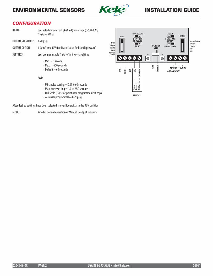
INPUT: User selectable current (4-20mA) or voltage (0-5/0-10V), Tri-state, PWM
OUTPUT STANDARD: 0-20 psig
OUTPUT OPTION: 4-20mA or 0-10V (feedback status for branch pressure)
SETTINGS: User programmable Tristate Timing–travel time
Min. = 1 second• Max. = 600 seconds• Default = 60 seconds•
PWM
Min. pulse setting = 0.01-0.60 seconds•Max. pulse setting = 1.0 to 75.0 seconds• Full Scale (FS) scale point user programmable 0-25psi• Zero user programmable 0-25psig•
After desired settings have been selected, move slide switch to the RUN position
MODE: Auto for normal operation or Manual to adjust pressure
confiGuration

ENVIRONMENTAL SENSORS INSTALLATION GUIDE
Z204948-0C PAGE 3 USA 888-397-5353 / [email protected] 06091
GND
INPU
T+
24V
CH2
CH1/
PWM
4-20
mA
0-10
V
A
LARM
CONT
ACTS
POWER SOURCE
BRANCH
PWM CONTACT
TRAP/FILTER
20-45psiRegulator
AIR COMPRESSOR
+-
PWM Control Example
Input switch set to "PWM"•Tri-State jumper set to "ON"•
GND
INPU
T+
24V
CH2
CH1/
PWM
4-20
mA
0-10
V
A
LARM
CONT
ACTS
POWER SOURCE
BRANCH
TRI-STATE CONTACTS
CH1OR
CH2OR
TRAP/FILTER
20-45psiRegulator
AIR COMPRESSOR
+- +-
Subt
ract
Pres
sure
Add
Pres
sure
Tri-state Control Example
Input switch set to "TRI-STATE"•Tri-State jumper set to "ON"•
wirinG
GND
INPU
T+
24V
CH2
CH1/
PWM
4-20
mA
0-10
V
A
LARM
CONT
ACTS
POWER SOURCE
Digital Input(Contact Closure)
4-20mA PROCESS METER
BRANCH
TRAP/FILTER
20-45psiRegulator
+-
Analog Out(0-5/0-10/4-20mA)Common
AIR COMPRESSOR
Current/Voltage Control, Current Output Example
Input switch settings same as example 1•Output jumper set to 4-20mA•
Current/Voltage Control, Voltage Output Example
GND
INPU
T+
24V
CH2
CH1/
PWM
4-20
mA
0-10
V
A
LARM
CONT
ACTS
POWER SOURCE
Digital Input(Contact Closure)
0-10V PROCESS METER
BRANCH
TRAP/FILTER
20-45psiRegulator
+-
Analog OutCommon
AIR COMPRESSOR
+-
Input switch set to voltage (0-5VDC or 0-10VDC)•Input volt jumper set to either 0-5VDC or 0-10VDC•Input switch set to 4-20mA•Output jumper set to 0-10VDC•

ENVIRONMENTAL SENSORS INSTALLATION GUIDE
Z204948-0C PAGE 4 USA 888-397-5353 / [email protected] 06091
4-20mAVoltageTristate
PWMNetwork
Control
INPUT
Tristate TimingNetworkFS PointZeroRUN
SETTING
sPecial instructions
4-20mAVoltageTristate
PWMNetwork
Control
INPUT
Tristate TimingNetworkFS PointZeroRUN
SETTING
Tristate TimingNetworkFS PointZeroRUN
SETTING
Tristate TimingNetworkFS PointZeroRUN
SETTING
PWM Mode
To ensure correct operation when using the tristate or PWM modes, use the tristate pullup.
To set the minimum pulse value, adjust the Setting and Input switches as shown:
"LO" will momentarily appear on the LCD, indicating that the minimum pulse width is being set. Use the (+) and (-) buttons to increase or decrease this value. To set the maximum pulse width, push both buttons simultaneously. "HI" will momentarily appear, indicating that the maximum pulse width is being set. Push both buttons to cycle between the "HI" and "LO" settings. Return the Setting slide switch to RUN to save these settings.
If the controller receives a pulse that is shorter than the minimum pulse width, the output will go to 0% of the range set with the zero and span settings. If the controller sees a pulse that is the same or longer than the maximum pulse width, the output will go to 100% of the range selected with the zero and span settings.
In this example the minimum pulse width is set to 0.60s, the maximum is set to 10s, zero is set to 0, and span is set to 10psi. Assume the controller receives a pulse of 5s duration:
Pulse range = 10s – 0.60s = 9.4s
Pressure range = span – zero = 10 – 0 = 10
Output = (5 / 9.4) x 10 = 5.3 psi
Tristate Mode
To ensure correct operation when using the tristate or PWM modes, use the tristate pullup.
Traveltime is defined as the contact closure time required to go from zero to full scale. If traveltime is set to 10 seconds and the TRISTATE 1 input is connected to ground for 5 seconds, the output will be 50%. If the input is connected to ground for another 5 seconds, the output will be 100%. If TRISTATE 2 (the decreasing input) is grounded for 10 seconds, the products output will return to 0%.
To set the travel time, adjust the Setting and Input switches as shown:
Press the (+) or (-) buttons to increase or decrease the travel time. Minimum travel time is 5 seconds; maximum is 600 seconds. Return the Setting switch to RUN to save all settings. The device's internal counters measure the contact closure time with 100Hz resolution.
Note: If Tristate input is to be operated by a triac output, use an AC relay to provide a dry contact closure to the UCP-822A input.
Tubing Length
Minimum tubing length is 15ft or an equivalent volume of 2.2 cubic inches. Shorter tubing lengths can cause the unit to oscillate.
Analog Output
The output is generated from the branch pressure. It is calculated as follows:
FS = Full Scale PointZero = Zero settingIn volt mode: Pressure = (10 / (FS - Zero)) * Voltage + Zero Voltage = (Pressure - Zero) / (FS - Zero) * 10In current mode: Pressure = (FS - Zero) * ((Current - 4) / 16) + Zero Current (in mA) = ((Pressure - Zero) / (FS - Zero)) * 16 + 4Examples: Zero setting = 5 psi; Span = 20 psi; Branch pressure = 16 psi Volt mode: Voltage = ((16 - 5) / (20 - 5)) * 10 = 7.33 V Current mode: Current = ((16 - 5) / (20 - 5)) * 16 + 4 = 15.73 mA
Alarms
Alarm contacts are closed in normal operation (auto mode setting).
Alarm Contact: Contacts open when no power is applied or when the device is in an alarm state.
Manual Mode Alarm: Contacts are open in manual mode setting. Contacts will then close for normal operation. Move the P-LOSS/MAN jumper to the manual mode setting. You do not need to power cycle the product after moving jumpers or the Auto/Manual switch.
Pressure Loss Alarm: Contacts open when the branch pressure falls and stays below 20% of the desired pressure for a period of 2 minutes.
FS Point and Zero Setting
To set the Zero or FS point, move the SETTING slide switch from Run to Zero or FS point setting, respectively.
The ‘Set’ icon will appear on the LCD. Using the (+) and (-) buttons add or decrease the pressure setpoints.
Blink Codes
Slow green Normal operation
Slow green with one fast red Manual mode alarm (contacts open)
Slow green with two fast reds Pressure loss alarm active (contacts open)
Slow red SETTINGS slide switch not in RUN position
Two fast reds Slide switch not in RUN position and Alarm (contacts open)
Three fast reds Over-voltage or over-current fault
Four fast reds Over pressure on branch side; over 25 psi
or