
Uccn1003 -may10_-_lab_04_-_intro_to_layer-1_network_devices-updated_30_june2010-2
description

1
UCCN1003 Data Communications and Networks
Lab 03: IP Subnets and Introduction to Routing Instructions:
1. Read the “Introduction” section for the background
2. Perform all the lab exercises, starting with exercise 1
3. Follow all the steps.
4. Record the results in all italic bold actions (by screen capture or copying).
5. Paste your screen captures on a Word Document and save it.
6. Answer all the questions in italic.
7. Write your answer in the same Word Document.
8. Please follow the sequence of the exercises, and don’t skip any step.
9. Please keep your word document. You will need it for your tests and exam.
10. Please try to understand the exercises and the commands, and don’t just type the
commands “blindly” without much studies and understanding.
Introduction
In this lab, you will learn how to form simple subnets. On the basis of these simple subnets, you
will build routes to enable the subnets to communicate among themselves. It is your
responsibility to study from the exercises on how the static routes work.
Exercise 1: Subnets in a Switch with Variable Subnet Mask
1. Open PacketTracer and build a network based on the following figure (with the
designated IP address and subnet mask).
PC0 = 10.0.1.1/8
PC1 = 10.0.1.2/16
PC2 = 10.0.1.3/24
PC3 = 10.0.2,1/8
PC4 = 10.0.2.2/16
PC5 = 10.0.2.3/24
2. Use PC0 to ping PC3, PC4 and PC5. Which PC can PC0 ping successfully?
3. Use PC1 to ping PC3, PC4 and PC5. Which PC can PC1 ping successfully?

2
4. Use PC2 to ping PC3, PC4 and PC5. Which PC can PC2 ping successfully?
5. Use PC2 to ping PC0, and PC1. Can PC2 ping successfully ping PC0 and PC1?
6. What can you deduce from the result why some pings are successful and others are not?
(Hint: check IP subnet rule)
Exercise 2: Strange IP Subnet
1. Set up the above network with the IP address and subnet mask, as indicated in the figure.
2. Use PC0, PC1, and PC2 to ping all other PCs. Which PC can be pinged successfully? If
we want all the PCs to be able to communicate with each other, we need a router.
3
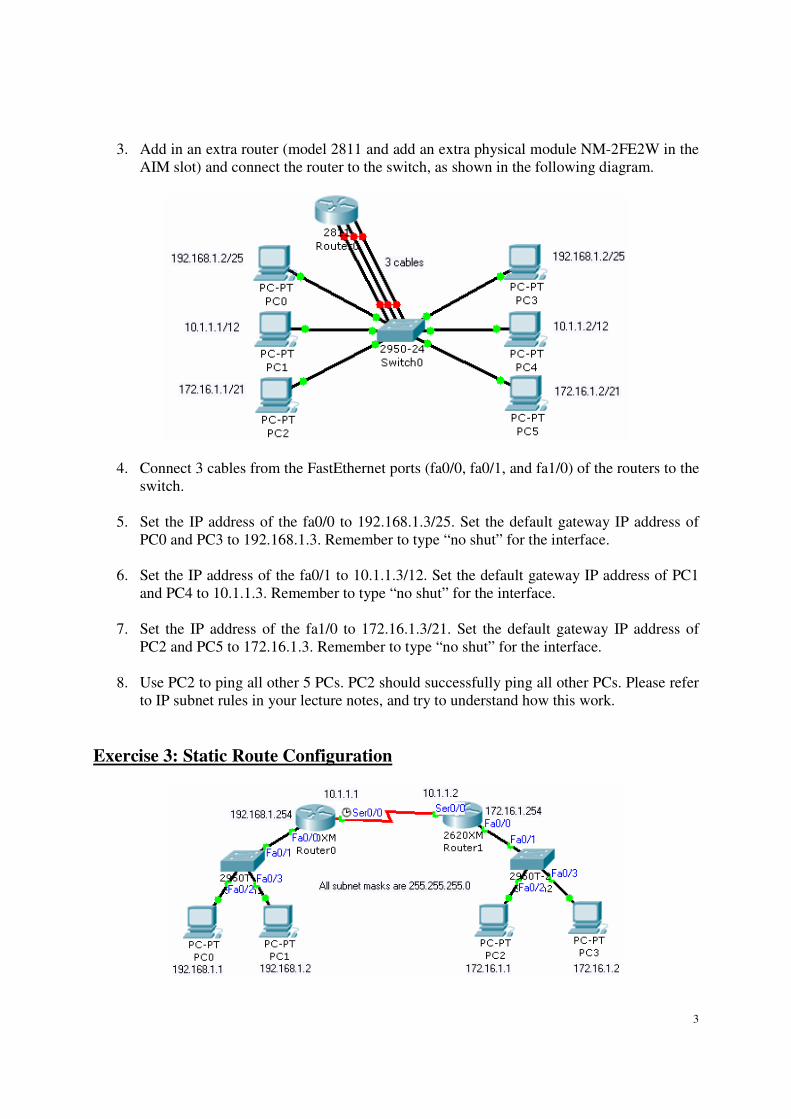
3. Add in an extra router (model 2811 and add an extra physical module NM-2FE2W in the
AIM slot) and connect the router to the switch, as shown in the following diagram.
4. Connect 3 cables from the FastEthernet ports (fa0/0, fa0/1, and fa1/0) of the routers to the
switch.
5. Set the IP address of the fa0/0 to 192.168.1.3/25. Set the default gateway IP address of
PC0 and PC3 to 192.168.1.3. Remember to type “no shut” for the interface.
6. Set the IP address of the fa0/1 to 10.1.1.3/12. Set the default gateway IP address of PC1
and PC4 to 10.1.1.3. Remember to type “no shut” for the interface.
7. Set the IP address of the fa1/0 to 172.16.1.3/21. Set the default gateway IP address of
PC2 and PC5 to 172.16.1.3. Remember to type “no shut” for the interface.
8. Use PC2 to ping all other 5 PCs. PC2 should successfully ping all other PCs. Please refer
to IP subnet rules in your lecture notes, and try to understand how this work.
Exercise 3: Static Route Configuration

4
Choose WIC-2T as your extra module for the
serial communication for both routers. Put the
module in the left WIC slot.
1. Build the above network with two 2620XM routers. In this exercise, we will learn how to
use and configure a serial connection. Add in an extra WIC-2T as shown in the above
figure.
2. Connect the two routers with serial DCE wire (Choose the cable with the above icon).
Remember to connect to serial0/0 of both routers.
3. Configure the IP addresses and gateway addresses for all PCs.
4. For Router0, refer to the following commands for IP address and static routing.
Router>enable
Router#config t
Router(config)#hostname Router0
Router0(config)#interface serial0/0
Router0(config-if)#ip address 10.1.1.1 255.255.255.0
Router0(config-if)#clock rate 128000
Router0(config-if)#no shutdown
Router0(config-if)#exit
Router0(config)#ip route 172.16.1.0 255.255.255.0 10.1.1.2
5. For Router1, configure the IP address and static routing.
Router>enable
Router#config t
Router(config)#hostname Router1
Router1(config)#interface serial0/0
Router1(config-if)#ip address 10.1.1.2 255.255.255.0
Router1(config-if)#clock rate 128000
Router1(config-if)#no shutdown
Router1(config-if)#exit
Router1(config)#ip route 192.168.1.0 255.255.255.0 10.1.1.1

5
6. If you set the static routes and configure the IP addresses correctly, PC0 should be able to
ping PC2 and PC3.
7. For serial connection, you need to set clock rate since it is synchronous connection.
Otherwise the serial connection won’t work properly. The unit of 128000 is bits per
second. You can set the clock rate of the serial line up to 4000000, but just remember to
set the same clock rate at both serial ports.
Exercise 4: Static Routing for Routers Connected a Switch
1. Build the following network with the IP addresses and gateway addresses stated in the
figure. All subnet masks are 255.255.255.0. Keep it as a good habit to change the
hostname of the router in CLI to match the name in the figure. Save the network as Lab3-
4-1.pkt. You will need this for exercise 6.
2. Set the static routes by referring to the following commands. Each router requires two
static routes to point to other subnets. Please study and understand the commands.
For Router0
===========
Router0(config)#ip route 192.168.2.0 255.255.255.0 200.1.1.2
Router0(config)#ip route 192.168.3.0 255.255.255.0 200.1.1.3
6
For Router1
===========
Router1(config)#ip route 192.168.1.0 255.255.255.0 200.1.1.1
Router1(config)#ip route 192.168.3.0 255.255.255.0 200.1.1.3
For Router2
===========
Router2(config)#ip route 192.168.2.0 255.255.255.0 200.1.1.2
Router2(config)#ip route 192.168.1.0 255.255.255.0 200.1.1.1
3. Use PC0 to ping other PCs in order to test the connectivity of all the subnets.
4. Check the routing tables of each routers by typing:
Router0#show ip route
Router1#show ip route
Router2#show ip route
5. Save your network as lab3-4-2.pkt. You will continue to expand this network in Exercise
5.
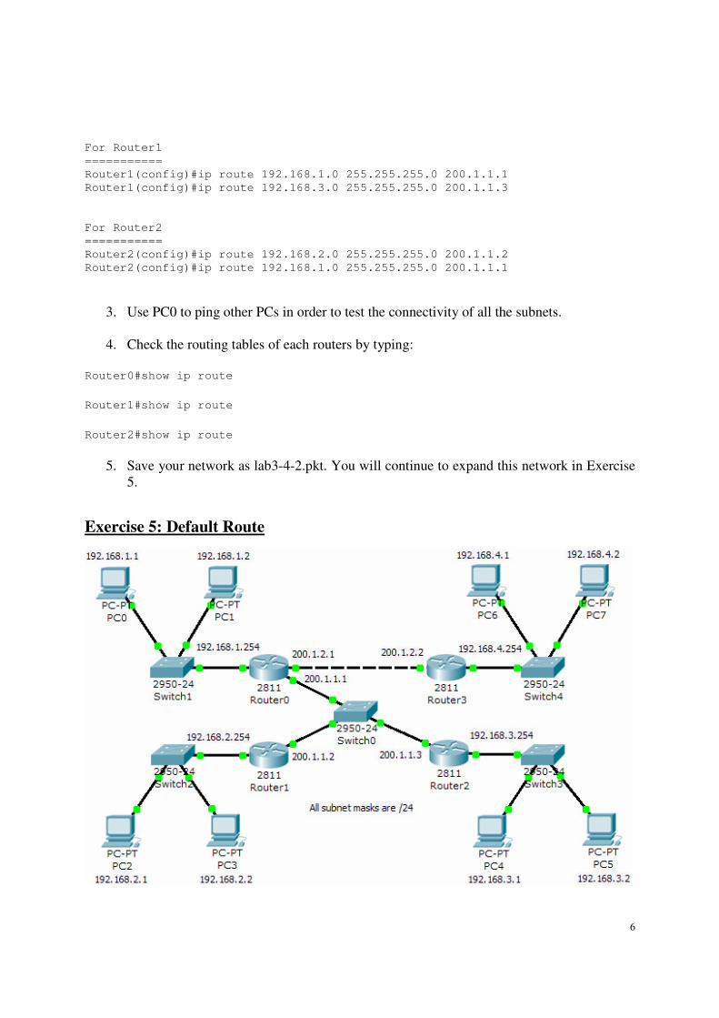
Exercise 5: Default Route

7
1. Based on the network in exercise 4, extend the network that includes subnet 192.168.4.0
as shown in figure. Backup the running-config file of Router0 to startup-config (“copy
run start”), while you add in an extra module NM-2FE2W to Router0, because you need
to on and off Router0.
2. Add in the static routes by referring to the following commands (assume that you have
done exercise 4 correctly). Please study and understand the commands on why the static
routes have to set in such as way.
For Router0
===========
Router0(config)#ip route 192.168.4.0 255.255.255.0 200.1.2.2
For Router1
===========
Router1(config)#ip route 192.168.4.0 255.255.255.0 200.1.1.1
For Router2
===========
Router2(config)#ip route 192.168.4.0 255.255.255.0 200.1.1.1
For Router3
===========
Router3(config)#ip route 0.0.0.0 0.0.0.0 200.1.2.1
3. Use PC0 to ping other PCs in order to test the connectivity of all the subnets.
4. Check the routing tables of each routers by typing:
Router0#show ip route
Router1#show ip route
Router2#show ip route
Router3#show ip route
5. Note: If you don’t use the default route in Router3 (ip route 0.0.0.0 0.0.0.0
next_hop_IP). You have to type the static route commands as shown in the following. In
a way, default route save you from typing some “extra” commands. (You do NOT need
to type the following commands in Router3.)
Router3(config)#ip route 192.168.1.0 255.255.255.0 200.1.2.1
Router3(config)#ip route 192.168.2.0 255.255.255.0 200.1.2.1
Router3(config)#ip route 192.168.3.0 255.255.255.0 200.1.2.1

8
Note on default route
ip route 0.0.0.0 0.0.0.0 next_hop_IP
A default route, also known as the gateway of last resort, is the network route used by a router
when no other known route exists for a given IP packet's destination address. All the packets for
destinations not known by the router's routing table are sent to the default route. This route
generally leads to another router, which treats the packet the same way: If the route is known, the
packet will get forwarded to the known route. If not, the packet is forwarded to the default-route
of that router which generally leads to another router.
Exercise 6: Dynamic Routing (Homework)
1. Load the file Lab3-4-1.pkt, and extend the network in Exercise 4 to include Router3,
Router4, Router5, Router6, and Router7 with the switches and the PCs. Please configure

9
the IP addresses and the gateway IP addresses according to the labels in the figure. Make
sure that you have NOT set any static routes in network.
2. Set the dynamic routes by referring to the following commands. Dynamic routes are
configured by software, in this case RIP (routing information protocol). Please study
them carefully. Basically, each router has to “advertise” the subnets attached to it with the
command “network a.b.c.d”, after the command “router rip”.
For Router0
===========
Router0(config)#router rip
Router0(config-router)#network 200.1.1.0
Router0(config-router)#network 192.168.1.0
Router0(config-router)#network 200.1.2.0
Router0(config-router)#exit
For Router1
===========
Router1(config)#router rip
Router1(config-router)#network 200.1.1.0
Router1(config-router)#network 192.168.2.0
Router1(config-router)#exit
For Router2
===========
Router2(config)#router rip
Router2(config-router)#network 200.1.1.0
Router2(config-router)#network 192.168.3.0
Router2(config-router)#exit
For Router3
===========
Router3(config)#router rip
Router3(config-router)#network 192.168.4.0
Router3(config-router)#network 200.1.2.0
Router3(config-router)#exit
For Router4
===========
Router4(config)#router rip
Router4(config-router)#network 200.1.1.0
Router4(config-router)#network 200.2.2.0
Router4(config-router)#exit
For Router5
===========
Router5(config)#router rip
Router5(config-router)#network 200.2.2.0
Router5(config-router)#network 192.168.5.0

10
Router5(config-router)#network 200.3.3.0
Router5(config-router)#exit
For Router6
===========
Router6(config)#router rip
Router6(config-router)#network 200.2.2.0
Router6(config-router)#network 192.168.7.0
Router6(config-router)#exit
For Router7
===========
Router7(config)#router rip
Router7(config-router)#network 200.3.3.0
Router7(config-router)#network 192.168.6.0
Router7(config-router)#exit
6. After you have key in all the commands, please wait for a while (around 3 minutes) for
the RIP software to configure the dynamic routes in all the routers.
7. Use one PC of each subnet to ping other PCs in order to test the connectivity of all the
subnets. Troubleshoot the network if necessary.
8. Check the routing tables of each router.
Router0#show ip route
Router1#show ip route
Router2#show ip route
Router3#show ip route
Router4#show ip route
Router5#show ip route
Router6#show ip route
Router7#show ip route


