
UC HASTINGS COLLEGE CONTENTS MEDIA … · Mounting locations for hardware. ... type, and quality to...
128
UC HASTINGS COLLEGE CONTENTS MEDIA SERVICES REMODEL 01/08/2015 - 1 - TABLE OF CONTENTS SECTION 00 01 10 TABLE OF CONTENTS DIVISION 08 – DOORS and WINDOWS 08 71 00 DOOR HARDWARE DIVISION 23 – HEATING, VENTILATING AND AIR-CONDITIONING (HVAC) 23 00 00 HEATING VENTILATION AND AIR CONDITIONING SYSTEM 25 00 00 BUILDING AUTOMATION SYSTEM END OF TABLE OF CONTENTS
Transcript of UC HASTINGS COLLEGE CONTENTS MEDIA … · Mounting locations for hardware. ... type, and quality to...

UC HASTINGS COLLEGE CONTENTS MEDIA SERVICES REMODEL
01/08/2015 - 1 - TABLE OF CONTENTS
SECTION 00 01 10
TABLE OF CONTENTS DIVISION 08 – DOORS and WINDOWS 08 71 00 DOOR HARDWARE DIVISION 23 – HEATING, VENTILATING AND AIR-CONDITIONING (HVAC) 23 00 00 HEATING VENTILATION AND AIR CONDITIONING SYSTEM 25 00 00 BUILDING AUTOMATION SYSTEM
END OF TABLE OF CONTENTS

MEDIA SERVICES RELOCATION UC HASTINGS COLLEGE OF LAW SAN FRANCISCO, CA
10/20/2014 - 2 - 08 71 00 Door Hardware
SECTION 08 71 00
DOOR HARDWARE
GENERAL
RELATED DOCUMENTS
A. Drawings and general provisions of Contract, including General and Supplementary Conditions of Division 1 Specification Sections, apply to this Section.
SUMMARY
A. This Section includes items known commercially as finish or door hardware that are required for swing, sliding, and folding doors, except special types of unique hardware specified in the same sections as the doors and door frames on which they are installed.
B. This Section includes the following, but is not necessarily limited to:
1. Door Hardware, including electric hardware. 2. Storefront and Entrance door hardware. 3. Door silencers or mutes.
C. Related Sections: The following sections are noted as containing requirements that relate to this Section, but may not be limited to this listing.
1. Division 8: Section - Steel Doors and Frames. 2. Division 8: Section - Wood Doors. 3. Division 8: Section - Aluminum Storefront 4. Division 28: Section - Fire/Life-Safety Systems & Security Access Systems.
REFERENCES (USE DATE OF STANDARD IN EFFECT AS OF BID DATE.)
A. 2013 California Building Code, CCR, Title 24.
B. BHMA – Builders’ Hardware Manufacturers Association
C. CCR – California Code of Regulations, Title 24, Part 2, California State Accessibility Standards.
D. DHI – Door and Hardware Institute
E. NFPA - National Fire Protection Association.
1. NFPA 80 - Fire Doors and Other Opening Protectives 2. NFPA 105 - Smoke and Draft Control Door Assemblies
F. UL - Underwriters Laboratories.
1. UL 10C - Fire Tests of Door Assemblies 2. UL 305 - Panic Hardware

MEDIA SERVICES RELOCATION UC HASTINGS COLLEGE OF LAW SAN FRANCISCO, CA
10/20/2014 - 3 - 08 71 00 Door Hardware
G. WHI - Warnock Hersey Incorporated
H. SDI - Steel Door Institute
SUBMITTALS & SUBSTITUTIONS
A. General: Submit in accordance with Conditions of the Contract and Division 1 Specification sections.
B. Submit product data (catalog cuts) including manufacturers' technical product information for each item of door hardware, installation instructions, maintenance of operating parts and finish, and other information necessary to show compliance with requirements.
C. Submit six (6) copies of schedule organized vertically into “Hardware Sets” with index of doors and headings, indicating complete designations of every item required for each door or opening. Include following information:
1. Include a Cover Sheet with; a. Job Name, location, telephone number. b. Architects name, location and telephone number. c. Contractors name, location, telephone number and job number. d. Suppliers name, location, telephone number and job number. e. Hardware consultant's name, location and telephone number.
2. Job Index information included; a. Numerical door number index including; door number, hardware heading number and
page number. b. Complete keying information (referred to DHI hand-book "Keying Systems and
Nomenclature"). Provision should be made in the schedule to provide keying information when available; if it is not available at the time the preliminary schedule is submitted.
c. Manufacturers' names and abbreviations for all materials. d. Explanation of abbreviations, symbols, and codes used in the schedule. e. Mounting locations for hardware. f. Clarification statements or questions. g. Catalog cuts and manufacturer’s technical data and instructions.
3. Vertical schedule format sample: Heading Number 1 (Hardware group or set number – HW -1) (a) 1 Single Door #1 - Exterior from Corridor 101 (b) 90 (c) RH (d) 3' 0"x7' 0" x 1-3/4" x (e) 20 Minute (f) WD x HM (g) 1 (h) (i) ea (j) Hinges - (k) 5BB1HW 4.5 x 4.5 NRP (l) ½ TMS (m) 626 (n) IVE
2 6AA 1 ea Lockset - ND50PD x RHO x RH x 10-025 x JTMS 626 SCH
(a) - Single or pair with opening number and location. (b) - Degree of opening (c) - Hand of door(s) (d) - Door and frame dimensions and door thickness. (e) - Label requirements if any. (f) - Door by frame material. (g) - (Optional) Hardware item line #. (h) - Keyset Symbol. (i) - Quantity. (j) - Product description. (k) - Product Number. (l) - Fastenings

MEDIA SERVICES RELOCATION UC HASTINGS COLLEGE OF LAW SAN FRANCISCO, CA
10/20/2014 - 4 - 08 71 00 Door Hardware
and other pertinent information. (m) - Hardware finish codes per ANSI A156.18. (n) - Manufacture abbreviation.
D. Make substitution requests in accordance with Division 1. Substitution requests must be made prior to bid date. Include product data and indicate benefit to the project. Furnish samples of any proposed substitution.
E. Wiring Diagrams: Provide product data and wiring and riser diagrams for all electrical products listed in the Hardware Schedule portion of this section.
F. Keying Schedule: Submit separate detailed schedule indicating clearly how the Owner's final instructions on keying of locks has been fulfilled.
G. Templates for doors, frames, and other work specified to be factory prepared for the installation of door hardware. Check shop drawings of other work to confirm that adequate provisions are made for locating and installing door hardware to comply with indicated requirements.
H. Furnish as-built/as-installed schedule with close-out documents, including keying schedule and transcript, wiring/riser diagrams, manufacturers’ installation and adjustment and maintenance information.
I. Fire Door Assembly Testing: Submit a written record of each fire door assembly to the Owner to be made available to the Authority Having Jurisdiction (AHJ) for future building inspections.
J. LEED Certification Points: Submit information and certifications necessary to achieve maximum points for LEED certification; coordinate and cooperate with Owner and Architect in providing information necessary for required LEED rating.
QUALITY ASSURANCE
A. Obtain each type of hardware (latch and lock sets, hinges, closers, exit devices, etc.) from a single manufacturer.
B. Supplier Qualifications: A recognized architectural door hardware supplier, with warehousing facilities in the project's vicinity, that has a record of successful in-service performance for supplying door hardware similar in quantity, type, and quality to that indicated for this project and that employs an experienced architectural hardware consultant (AHC) who is available to Owner, Architect, and Contractor, at reasonable times during the course of the Work, for consultation.
1. Responsible for detailing, scheduling and ordering of finish hardware. 2. Meet with Owner to finalize keying requirements and to obtain final instructions in writing.
To maintain the integrity of patented key systems provide a letter of authorization from the specified manufacturer indicating that supplier has authorization to purchase the key system directly from the manufacturer.
3. Stock parts for products supplied and are capable of repairing and replacing hardware items found defective within warranty periods.
C. Hardware Installer: Company specializing in the installation of commercial door hardware with five years documented experience.

MEDIA SERVICES RELOCATION UC HASTINGS COLLEGE OF LAW SAN FRANCISCO, CA
10/20/2014 - 5 - 08 71 00 Door Hardware
D. Fire-Rated Openings: Provide door hardware for fire-rated openings that complies with NFPA Standard No. 80 and requirements of authorities having jurisdiction. Provide only items of door hardware that are listed and tested by UL or Warnock Hersey for given type/size opening and degree of label. Provide proper latching hardware, door closers, approved-bearing hinges and seals whether listed in the Hardware Schedule or not.
1. Where emergency exit devices are required on fire-rated doors, (with supplementary marking on doors' UL labels indicating "Fire Door to be Equipped with Fire Exit Hardware") provide UL label on exit devices indicating "Fire Exit Hardware".
E. Exit Doors: Operable from inside with single motion without the use of a key or special knowledge or effort.
DELIVERY, STORAGE AND HANDLING
A. Coordinate delivery of packaged hardware items to the appropriate locations (shop or field) for installation.
B. Hardware items shall be individually packaged in manufacturers’ original containers, complete with proper fasteners. Clearly mark packages on outside to indicate contents and locations in hardware schedule and in work.
C. Provide locked storage area for hardware, protect from moisture, sunlight, paint, chemicals, etc.
D. Inventory door hardware jointly with representatives of hardware supplier and hardware installer until each is satisfied that count is correct.
WARRANTY
A. Provide warranties of respective manufacturers’ regular terms of sale from day of final acceptance as follows:
1. Locksets: “L” Series – Three (3) years; “ND” Series - Ten (10) years. 2. Electronic Locks: One (1) year. 3. Closers: 4000 Series - Thirty (30) years; 1260 Series - Twenty (20) years; Concealed
High Security - Fifteen (15) years; except electronic closers shall be Two (2) years. 4. Exit devices: Three (3) years. 5. All other hardware: Two (2) years.
MAINTENANCE
A. Maintenance Tools and Instructions: Furnish a complete set of specialized tools and maintenance instructions as needed for Owner's continued adjustment, maintenance, and removal and replacement of door hardware.
PRE-INSTALLATION CONFERENCE
A. Convene a pre-installation conference at least one week prior to beginning work of this section.
B. Attendance: Architect, Construction Manager, Contractor, Security Contractor, Hardware Supplier, Installer, Key District Personnel, and Project Inspector.

MEDIA SERVICES RELOCATION UC HASTINGS COLLEGE OF LAW SAN FRANCISCO, CA
10/20/2014 - 6 - 08 71 00 Door Hardware
C. Agenda: Review hardware schedule, products, installation procedures and coordination required with related work. Review District's keying standards.
PRODUCTS
MANUFACTURERS
Item Manufacturer Acceptable Substitutes
A. Hinges Ives Hager, Stanley, McKinney
B. Locks, Latches & Cylinders Schlage None
C. Closers LCN None
D. Stops Ives Trimco, BBW, DCI
E. Seals & Bottoms Zero Or Approved Equal
MATERIALS
A. Hinges: Exterior out-swinging door butts shall be non-ferrous material and shall have stainless steel hinge pins. All doors to have non-rising pins.
1. Hinges shall be sized in accordance with the following: a. Height:
1) Doors up to 42" wide: 4-1/2" inches. 2) Doors 43" to 48" wide: 5 inches.
b. Width: Sufficient to clear frame and trim when door swings 180 degrees. c. Number of Hinges: Furnish 3 hinges per leaf to 7'-5" in height. Add one for each
additional 2 feet in height.
2. Furnish non-removable pins (NRP) at all exterior out-swing doors and interior key lock doors with reverse bevels.
B. Heavy Duty Cylindrical Locks and Latches: Schlage "ND" Series as scheduled with "Rhodes" design, fastened with through-bolts and threaded chassis hubs.
1. Locksets to comply with ANSI A156.2, Series 4000, Grade 1; tested to exceed 3,000,000 cycles. Locksets shall meet ANSI A117.1, Accessible Code.
2. Chassis: One piece modular assembly and multi-functional allowing function interchange without disassembly of lockset.
3. Spindle shall be deep-draw manufactured not stamped. Spindle and spring cage to be one-piece integrated assembly.
4. Anti-rotation plate to be interlocking to the lock chassis. Lock design utilizing bit-tabs are not acceptable.
5. Lever Trim: Accessible design, bi-directional, independent assemblies. 6. Locks shall be of such construction that when locked, the door may be opened from
within by using lever and without the use of a key or special knowledge. 7. Thru-bolts to secure anti-rotation plate without sheer line. Fully threaded thru-bolts are
not acceptable. 8. Spring cage to have double compression springs. Manufacturers utilizing torsion springs
are not acceptable.

MEDIA SERVICES RELOCATION UC HASTINGS COLLEGE OF LAW SAN FRANCISCO, CA
10/20/2014 - 7 - 08 71 00 Door Hardware
9. Latchbolt to be steel with minimum ½” throw deadlatch on keyed and exterior functions; ¾” throw anti-friction latchbolt on pairs of doors.
10. Strikes: ANSI curved lip,1-1/4” x 4-7/8”, with 1” deep dust box (K510-066). Lips shall be of sufficient length to clear trim and protect clothing.
C. Closers: LCN as scheduled. Place closers inside building, stairs, room, etc.
1. Door closer cylinders shall be of high strength cast iron construction with double heat treated pinion shaft to provide low wear operating capabilities of internal parts throughout the life of the installation. All door closers shall be tested to ANSI/BHMA A156.4 test requirements by a BHMA certified testing laboratory. A written certification showing successful completion of a minimum of 10,000,000 cycles must be provided.
2. All door closers shall be fully hydraulic and have full rack and pinion action with a shaft diameter of a minimum of 11/16 inch and piston diameter of 1 inch to ensure longevity and durability under all closer applications.
3. All parallel arm closers shall incorporate one piece solid forged steel arms with bronze bushings. 1-9/16” steel stud shoulder bolts, shall be incorporated in regular arms, hold-open arms, arms with hold open and stop built in. All other closers to have forged steel main arms for strength, durability, and aesthetics for versatility of trim accommodation, high strength and long life.
4. All parallel arm closers so detailed shall provide advanced backcheck for doors subject to severe abuse or extreme wind conditions. This advanced backcheck shall be located to begin cushioning the opening swing of the door at approximately 45 degrees. The intensity of the backcheck shall be fully adjustable by tamper resistant non-critical screw valve.
5. Closers shall be installed to permit doors to swing 180 degrees. 6. All closers shall utilize a stable fluid withstanding temperature range of 120 degrees F. to
-30 degrees F. without requiring seasonal adjustment of closer speed to properly close the door.
7. Provide the manufactures drop plates, brackets and spacers as required at narrow head rails and special frame conditions. NO wood plates or spacers will be allowed.
8. Maximum effort to operate closers shall not exceed 5 lbs., such pull or push effort being applied at right angles to hinged doors. Compensating devices or automatic door operators may be utilized to meet the above standards. When fire doors are required, the maximum effort to operate the closer may be increased but shall not exceed 15 lbs. when specifically approved by fire marshal. All closers shall be adjusted to operate with the minimum amount of opening force and still close and latch the door. These forces do not apply to the force required to retract latch bolts or disengage other devices that hold the door in a closed position. Door shall take at least 3 seconds to move from an open position of 70 degrees to a point of 3 inches from the latch jamb.
9. Provide sex-bolted or through bolt mounting for all door closers.
D. Door Stops:
1. Unless otherwise noted in Hardware Sets, provide floor type with appropriate fasteners. Where wall type cannot be used, provide floor type. If neither can be used, provide overhead type.
2. Do not install floor stops more than four (4) inches from the face of the wall or partition (CBC Section 11B-307).
3. Overhead stops shall be made of stainless steel and non-plastic mechanisms and finished metal end caps. Field-changeable hold-open, friction and stop-only functions.
E. Thresholds: As Scheduled and per details.
1. Thresholds shall not exceed 1/2" in height, with a beveled surface of 1:2 maximum slope.

MEDIA SERVICES RELOCATION UC HASTINGS COLLEGE OF LAW SAN FRANCISCO, CA
10/20/2014 - 8 - 08 71 00 Door Hardware
2. Set thresholds in a full bed of butyl-rubber or polyisobutylene mastic sealant complying with requirements in Division 7 “Thermal and Moisture Protection”.
3. Use ¼” fasteners, red-head flat-head sleeve anchors (SS/FHSL). 4. Thresholds shall comply with CBC Section 11B-204.1.
F. Seals: Provide silicone gasket at all rated and exterior doors.
1. Fire-rated Doors, Resilient Seals: UL10C Classified complies with NFPA 80 & NFPA 252. Coordinate with selected door manufacturers' and selected frame manufacturers' requirements.
2. Fire-rated Doors, Intumescent Seals: Furnished by selected door manufacturer. Furnish fire-labeled opening assembly complete and in full compliance with UL10C Classified complies with NFPA 80 & NFPA 252. Where required, intumescent seals vary in requirement by door type and door manufacture -- careful coordination required.
3. Smoke & Draft Control Doors, Provide UL10C Classified complies with NFPA 80 & NFPA 252 for use on “S” labeled Positive Pressure door assemblies.
G. Silencers: Furnish silencers for interior hollow metal frames, 3 for single doors, 2 for pairs of doors. Omit where sound or light seals occurs, or for fire-resistive-rated door assemblies.
KEYING
A. Furnish a Proprietary Schlage masterkey system as directed by the owner or architect. Campus keyway standard is “FG.”
B. Extend the original Schlage masterkey system established for the project named ________________________ located in ____________________under Schlage Structure # _________
C. Furnish all cylinders in the Schlage conventional style except the exit device and removable mullion cylinders which will be supplied in Schlage Full Size Interchangable Core (FSIC). Pack change keys independently (PKI).
D. Furnish all keys with visual key control.
1. Stamp key “Do Not Duplicate”. 2. Delete key section identifier from the key bow. 3. Delete key “bitting” from the key bow.
E. Furnish mechanical keys as follows:
1. Furnish 2 cut change keys for each different change key code. 2. Furnish 1 uncut key blank for each change key code. 3. Furnish 6 cut masterkeys for each different masterkey set. 4. Furnish 3 uncut key blanks for each masterkey set. 5. Furnish 2 cut control keys cut to the top masterkey for permanent I/C cylinders. 6. Furnish 1 cut control key cut to each SKD combination.
F. Furnish Keying Transcript (50-123) to owner. End-user to provide letter of authorization to hardware dealer to allow Schlage to mail transcript (bitting list) to the end-user or designated representative.
FINISHES

MEDIA SERVICES RELOCATION UC HASTINGS COLLEGE OF LAW SAN FRANCISCO, CA
10/20/2014 - 9 - 08 71 00 Door Hardware
A. Generally to be satin chrome US26D (626 on bronze and 652 on steel) unless otherwise noted.
B. Furnish push plates, pull plates and kick or armor plates in satin stainless steel US32D (630) unless otherwise noted.
C. Door closers shall be powder-coated to match other hardware, unless otherwise noted.
D. Aluminum items to be finished anodized aluminum except thresholds which can be furnished as standard mill finish.
FASTENERS
A. Screws for strikes, face plates and similar items shall be flat head, countersunk type, provide machine screws for metal and standard wood screws for wood.
B. Screws for butt hinges shall be flathead, countersunk, full-thread type.
C. Fastening of closer bases or closer shoes to doors shall be by means of sex bolts and spray painted to match closer finish.
D. Provide expansion anchors for attaching hardware items to concrete or masonry.
E. All exposed fasteners shall have a phillips head.
F. Finish of exposed screws to match surface finish of hardware or other adjacent work.
G. All Exit Devices and Lock Protectors shall be fastened to the door by the means of sex bolts or through bolts.
EXECUTION
INSPECTION
A. Verify that doors and frames are square and plumb and ready to receive work and dimensions are as instructed by the manufacturer.
B. Beginning of installation means acceptance of existing conditions.
C. Fire-Rated Door Assembly Inspection: Upon completion of the installation, all fire door assemblies shall be inspected to confirm proper operation of the closing device and latching device and that only the manufacturer’s furnished fasteners are used for installation and that it meets all criteria of a fire door assembly per NFPA 80 (Standard for Fire Doors and Other Opening Protectives) 2013 Edition. A written record shall be maintained and transmitted to the Owner to be made available to the Authority Having Jurisdiction (AHJ). The inspection of the swinging fire doors shall be performed by a certified FDAI (Fire Door Assembly Inspector) with knowledge and understanding of the operating components of the type of door being subjected to the inspection. The record shall list each fire door assembly throughout the project and include each door number, an itemized list of hardware set components at each door opening, and each door location in the facility.
INSTALLATION
A. Install hardware in accordance with manufacturer's instructions and requirements of DHI.

MEDIA SERVICES RELOCATION UC HASTINGS COLLEGE OF LAW SAN FRANCISCO, CA
10/20/2014 - 10 - 08 71 00 Door Hardware
B. Use the templates provided by hardware item manufacturer.
C. Mounting heights for hardware shall be as recommended by the Door and Hardware Institute. Operating hardware will to be located between 30" and 44" AFF.
D. Set units level, plumb and true to line and location. Adjust and reinforce the attachment substrate as necessary for proper installation and operation.
E. Drill and countersink units that are not factory-prepared for anchorage fasteners. Space fasteners and anchors in accordance with industry standards.
F. Set thresholds for exterior doors in full bed of butyl-rubber sealant.
G. If hand of door is changed during construction, make necessary changes in hardware at no additional cost.
H. Hardware Installer shall coordinate with security contractor to route cable to connect electrified locks, panic hardware and fire exit hardware to power transfers or electric hinges at the time these items are installed so as to avoid disassembly and reinstallation of hardware.
I. Hardware Installer shall also be present with the security contractor when the power is turned on for the testing of the electronic hardware applications. Installer shall make adjustments to solenoids, latches, vertical rods and closers to insure proper and secure operation.
J. All wiring for electro-mechanical hardware mounted on the door shall be connected through the power transfer and terminated in the interface junction box specified for in the Electrical Section.
K. Conductors shall be minimum 18 gage stranded, multicolored. A minimum 12 in. loop of conductors shall be coiled in the interface junction box. Each conductor shall be permanently marked with its function.
L. If a power supply is specified in the hardware sets, all conductors shall be terminated in the power supply. Make all connections required for proper operation between the power supply and the electro-mechanical hardware. Provide the proper size conductors as specified in the manufacturer’s technical documentation.
ADJUST AND CLEAN
A. Adjust and check each operating item of hardware and each door, to ensure proper operation or function of every unit. Replace units which cannot be adjusted to operate freely and smoothly as intended for the application made.
B. Clean adjacent surface soiled by hardware installation.
C. Final Adjustment: Wherever hardware installation is made more than one month prior to acceptance or occupancy, return to that work area and make final check and adjustment of all hardware items in such space or area. Clean operating items as necessary to restore proper function and finish of hardware and doors. Adjust door control devices to compensate for final operation of heating and ventilating equipment.
D. Instruct Owner's Personnel in proper adjustment and maintenance of hardware finishes, during the final adjustment of hardware.

MEDIA SERVICES RELOCATION UC HASTINGS COLLEGE OF LAW SAN FRANCISCO, CA
10/20/2014 - 11 - 08 71 00 Door Hardware
E. Continued Maintenance Service: Approximately six months after the completion of the project, the Contractor accompanied by the Architectural Hardware Consultant, shall return to the project and re-adjust every item of hardware to restore proper functions of doors and hardware. Consult with and instruct Owner's personnel in recommended additions to the maintenance procedures. Replace hardware items which have deteriorated or failed due to faulty design, materials or installation of hardware units. Prepare a written report of current and predictable problems (of substantial nature) in the performance of the hardware.
HARDWARE LOCATIONS
A. Conform to CCR, Title 24, Part 2; and ADAAG; and the drawings for access-compliant positioning requirements for the disabled.
FIELD QUALITY CONTROL
A. Hardware supplier is responsible for providing the services of an Architectural Hardware Consultant (AHC) or a proprietary product technician to inspect installation and certify that hardware and its installation have been furnished and installed in accordance with manufacturers’ instructions and as specified herein.
SCHEDULE
A. The items listed in the following schedule shall conform to the requirements of the foregoing specifications.
B. The Door Schedule on the Drawings indicates which hardware set is used with each door.
Manufacturers Abbreviations (Mfr.)
IVE = Ives Hinges, Pivots, Bolts, Coordinators, Dust Proof Strikes, Push Pull & Kick Plates, Door Stops & Silencers LCN = LCN Door Closers SCH = Schlage Lock Company Locks, Latches & Cylinders
SPEXTRA: 161819
HARDWARE GROUP NO. 01
EACH TO HAVE: QTY DESCRIPTION CATALOG NUMBER FINISH MFR
3 EA HINGE 5BB1 4.5 X 4.5 652 IVE 1 EA CLASSROOM LOCK ND70PD RHO 626 SCH 1 EA WALL STOP WS406/407CCV 626 IVE 3 EA SILENCER PER ALUMINUM FRAME MFR
HARDWARE GROUP NO. 02 – NOT USED
MEDIA SERVICES RELOCATION UC HASTINGS COLLEGE OF LAW SAN FRANCISCO, CA
10/20/2014 - 12 - 08 71 00 Door Hardware
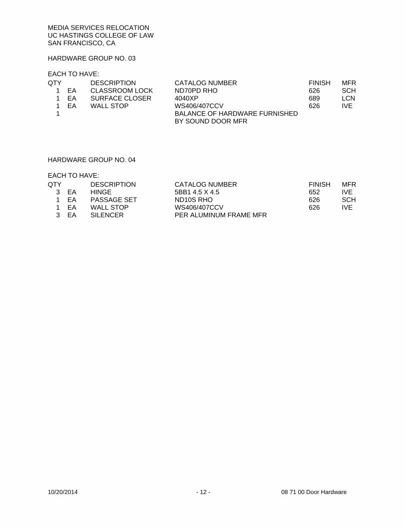
HARDWARE GROUP NO. 03
EACH TO HAVE: QTY DESCRIPTION CATALOG NUMBER FINISH MFR
1 EA CLASSROOM LOCK ND70PD RHO 626 SCH 1 EA SURFACE CLOSER 4040XP 689 LCN 1 EA WALL STOP WS406/407CCV 626 IVE 1 BALANCE OF HARDWARE FURNISHED
BY SOUND DOOR MFR
HARDWARE GROUP NO. 04
EACH TO HAVE: QTY DESCRIPTION CATALOG NUMBER FINISH MFR
3 EA HINGE 5BB1 4.5 X 4.5 652 IVE 1 EA PASSAGE SET ND10S RHO 626 SCH 1 EA WALL STOP WS406/407CCV 626 IVE 3 EA SILENCER PER ALUMINUM FRAME MFR

UC HASTINGS COLLEGE HEATING VENTILATING & AIR CONDITIONING SYSTEM REMODEL
MEDIA SERVICE REMODEL
10/19/2014 Page 1 of 29 230000 HVAC System Taylor Engineering LLC
UC HASTINGS MEDIA SERVICE REMODEL
230000 HEATING VENTILATING & AIR CONDITIONING SYSTEM
PART 1 - GENERAL
1.1 DESCRIPTION
A. Project Overview
1. UC Hastings building is an 185,000 ft2 6-story office building in San Francisco, CA built in 1980. This project consists of the remodel of a fourth floor computer lab totaling approximately 925 square feet (Originally room 441) into media service rooms.
2. The HVAC system consists of a VAV terminal unit (VAV-4-4) feed by the main air handling unit (AC-4) and a ceiling mounted water cooled AC unit (AC-41).
3. Cooling is provided by roof mounted and ceiling mounted water cooled AC units. There are two 146 ton cooling towers.
4. Heating provided by a steam to water heat exchanger that is served by purchased district steam.
B. Work Scope Summary
1. The remodel of the HVAC system in the fourth floor future Media Service area to accommodate the remodel of the space. The space is divided into four new thermal zones, each conditioned by a VAV terminal unit with reheat coil. If AC-4 has enough capacity, all four VAV units shall connect to AC-4 main duct and the existing AC-41 and its associated ductwork shall be demolished with the associated utilities safely secured and capped. If the airflow capacity from AC-4 is not adequate, the new design shall take advantage of the AC-41 by adding a variable speed drive to provide the limited necessary additional cooling to achieve the zoning as described.
2. Replace controls; see 250000 Building Automation Systems specification section.
3. Design and balance the airflows for the VAV boxes for IT open offices room 440.
1.2 SCOPE OF WORK
A. Design/Assist Approach
1. The work for this project will be built using a “design/assist” approach. The design/assist contractor (“Contractor”) and Taylor Engineering (“Engineer”) shall share design responsibilities as indicated herein.
2. The table below indicates engineering responsibility assignments for the Contractor and the Engineer.
Item Contractor Engineer
Engineer-of-Record P − Mechanical system program requirements R P Equipment sizing P R Control system design (separate contract) N P Construction details (see note below) P R Seismic restraints P R Completion of permit drawings P R Title 24 Compliance Documentation P R Project construction management P N Construction and all field work P R Construction quality control P N Start-up & commissioning P S
3. Explanatory Notes

UC HASTINGS COLLEGE HEATING VENTILATING & AIR CONDITIONING SYSTEM REMODEL
MEDIA SERVICE REMODEL
10/19/2014 Page 2 of 29 230000 HVAC System Taylor Engineering LLC
a. Primary (P) responsibility shall mean making all decisions and taking engineer/contractor-of-record responsibility for the item.
b. Secondary (S) responsibility shall mean taking an active role assisting the party with primary responsibility for the item.
c. Review (R) shall mean that the party shall review and comment on the work done by the party with primary responsibility for the item.
d. No (N) responsibility shall mean the party will have no role with regard to the item.
e. “Construction details” includes wall, roof, and floor penetration details, piping, ductwork, and equipment details and supports, vibration isolation details, housekeeping pad layouts and dimensioning, etc.
4. The Contractor shall be the engineer-of-record as well as the contractor of record and responsible for all required work.
B. Work Included: Design, furnish, and install all equipment and systems specified herein and as required for complete and fully functional systems. This is a turn-key project. There are no other contractors working on this project. All work that is required shall be performed by the Contractor, including but not limited to the following.
1. Demolition
2. New equipment
3. Electrical work
4. Seismic restraints
5. Electrical power wiring, disconnects, etc. for new equipment
6. Test and balance
7. Operator training
8. Overtime labor if required
C. Work Excluded:
1. Cost of repairing existing equipment that is specified to be reused, if required.
2. Asbestos abatement. If asbestos is discovered during the course of the work, Contractor shall notify Owner who will retain abatement contractor.
3. Temporary cooling equipment for spaces served by existing auxiliary cooling systems if required for period that auxiliary cooling system is inoperative. This will be done by the building engineering staff. Contractor must coordinate with engineering staff in advance. See also Paragraph 1.10B.
4. Controls. Controls will be installed by a separate controls contractor at the same time as the remodel. No controls work is required in this contract unless specifically identified. However, this contractor shall coordinate with the controls contractor so that work can be done simultaneously. See Scope of Work coordination in 250000 Building Automation Systems specification section.
5. Permit fees (paid by owner)
1.3 CONTRACTOR PROPOSALS
A. Contractor shall visit site prior to bid. Ascertain and check all conditions and take all measurements that may affect the work. Drawings provided with this specification are to be used at Contractor’s risk; drawings are schematic and may or may not be drawn accurately. No allowance shall subsequently be made for any additional expenses or claims due to the failure or neglect under this section to make such examination, including examination of restricted working conditions or such other difficulties that can be visually observed during site visit.
B. By submitting a price, Contractor guarantees that the proposal is complete and turn-key, except where specific exceptions are provided herein or clearly noted in the Contractor’s proposal.
C. Prior to bid, Contractor shall coordinate acceptable downtime periods with building management. Price shall include any overtime required for this project.

UC HASTINGS COLLEGE HEATING VENTILATING & AIR CONDITIONING SYSTEM REMODEL
MEDIA SERVICE REMODEL
10/19/2014 Page 3 of 29 230000 HVAC System Taylor Engineering LLC
D. Proposals shall include:
1. Pricing using bid form attached.
a. Provide break-out prices indicated.
b. Provide alternate pricing indicated, plus any additional alternates at contractor’s option.
2. Description of installation plan.
3. A preliminary schedule of installation including final date of completion for the project assuming all measures are implemented.
4. Any exclusions in addition to those already clearly excluded in these specifications. Do not exclude anything that is obviously required for the project; this is a turn-key project. Do not repeat exclusions that are already clearly listed in these specifications.
1.4 REFERENCE STANDARDS
A. Requirements of Regulatory Agencies:
1. Nothing in Drawings or Specifications shall be construed to permit Work not conforming to applicable laws, ordinances, rules, regulations.
2. When drawings or Specifications exceed requirements of applicable laws, ordinances, rules and regulations, comply with documents establishing the more stringent requirement.
3. Applicable codes include the current version of those listed below, in addition to others specified in individual sections:
a. CBC – California Building Code
b. CMC – California Mechanical Code
c. San Francisco City and County Codes, Ordinances, and Code Amendments
d. The State of California Codes
4. If any of above requirements is in conflict with one another, or with Specifications' requirements, the most stringent requirement shall govern. Where codes are silent on an issue, NFPA Standards shall apply.
B. Published specifications, standards, tests or recommended method of trade, industry or governmental organizations as listed below apply to all work in this Section:
1. AABC - Associated Air Balance Council
2. ADC - Air Diffuser Balance Council
3. AMCA - Air Moving and Conditioning Association
4. ANSI - American National Standards Institute
5. ARI - Air Conditioning and Refrigeration Institute
6. ASHRAE - American Society of Heating, Refrigeration and Air Conditioning Engineers
7. ASME - American Society of Mechanical Engineers
8. ASTM - American Society for Testing and Materials
9. ETL - Intertek Semko (Formerly Electrical Testing Laboratories)
10. IEEE - Institute of Electrical and Electronic Engineers
11. NEMA - National Electrical Manufacturer's Association
12. NFPA - National Fire Protection Association
13. SMACNA - Sheet Metal and Air Conditioning Contractors National Association
14. UL - Underwriters' Laboratories
C. Industry standards and manufacturers' recommendations, diagrams or requirements shall be strictly adhered to for installation of materials and equipment.
1.5 QUALITY ASSURANCE
A. All equipment and accessories to be the product of a manufacturer regularly engaged in its manufacture.

UC HASTINGS COLLEGE HEATING VENTILATING & AIR CONDITIONING SYSTEM REMODEL
MEDIA SERVICE REMODEL
10/19/2014 Page 4 of 29 230000 HVAC System Taylor Engineering LLC
B. All items of a given type shall be the products of same manufacturer.
C. Supply all equipment and accessories new and free from defects.
D. Supply all equipment and accessories in compliance with the applicable standards listed in Paragraph 1.4 with all applicable national, state and local codes.
1.6 DEFINITIONS
A. “Provide": to supply, install and connect up complete and ready safe and regular operation of particular work referred to unless specifically noted.
B. "Install": to erect, mount and connect complete with related accessories.
C. "Supply": to purchase, procure, acquire and deliver complete with related accessories.
D. "Work": labor, materials, equipment, apparatus, controls, accessories, and other items required for proper and complete installation.
E. "Piping": pipe, tube, fittings, flanges, valves, controls, strainers, hangers, supports, unions, traps, drains, insulation, and related items.
F. "Wiring": raceway, fittings, wire, boxes and related items.
G. "Concealed": embedded in masonry or other construction, installed in furred spaces, within double partitions or hung ceilings, in trenches, in crawl spaces, or in enclosures.
H. "Exposed": not installed underground or "concealed" as defined above.
I. "Indicated," "shown" or "noted": as indicated, shown or noted on drawings or specifications.
J. "Similar" or "equal": of base bid manufacture, equal in materials, weight, size, design, and efficiency of specified product, conforming to PART 2 Materials.
K. "Reviewed," "satisfactory," or "directed": as reviewed, satisfactory, or directed by or to Architect.
L. "Motor Controllers": manual or magnetic starters (with or without switches), individual pushbuttons or hand-off-automatic (HOA) switches controlling the operation of motors.
M. "Control or Actuating Devices": automatic sensing and switching devices such as thermostats, pressure, float, electro-pneumatic switches and electrodes controlling operation of equipment.
1.7 DESIGN DOCUMENTS
A. An employee of the HVAC Contractor shall serve as Engineer-of-Record. (A third party consulting engineer is acceptable only if consultant has significant design/build experience and a record of working with the HVAC Contractor on past projects of this size and complexity.)
B. All design documents shall be prepared under the supervision of the Engineer-of-Record.
C. Design
1. Drawings are to be created in AutoCAD format, version 2010 or later AutoCAD. Revit 2014.
2. Drawings shall be complete for use as on-going comprehensive record drawings. Existing systems and equipment shall be shown with dashed lines. The purpose is to make new drawings complete so that existing system drawings no longer are required to fully describe mechanical systems.
3. Areas Covered by Drawings
a. Fourth floor Media Service Area and adjacent IT open offices room 440.
4. Drawings of covered areas shall include:
a. All new and existing equipment:
1) Tag all equipment
2) Schedule all new and existing equipment
b. All new and existing ducts and grilles
1) Tag all ducts with duct sizes and elevations
2) Tag all grilles with grille size and airflow
c. All new and existing hot water piping and condensate piping

UC HASTINGS COLLEGE HEATING VENTILATING & AIR CONDITIONING SYSTEM REMODEL
MEDIA SERVICE REMODEL
10/19/2014 Page 5 of 29 230000 HVAC System Taylor Engineering LLC
1) Tag all piping with sizes and service
1.8 SUBMITTALS
A. Schedule
1. Allow 10 working days for approval, unless Engineer agrees to accelerated schedule.
B. Submit drawings, product data, samples and certificates of compliance required as hereinafter specified in this Section.
C. Submission Procedure
1. Initial Submittal
a. Submit one electronic copy of product data in word-searchable format such as Adobe pdf via email. Paper copies will not be accepted.
b. Submittal will be reviewed and comments returned to Contractor
2. Resubmission
a. Make any corrections or change in submittals as required
b. Resubmit for review in electronic format described above until no exceptions are taken
c. The cost of Taylor Engineering’s review of submittals after first resubmittal will be borne by Contractor at Taylor Engineering standard billing rates
3. Final approval: Once submission is accepted, Contactor shall print two bound sets of submittals for Owner. Taylor Engineering does not require or desire paper copies.
D. Contents of Submittals
1. HVAC Equipment Submittals
a. Manufacturer's name and model number
b. All information required to completely describe materials and equipment and to indicate compliance with drawings and specifications, including, but not limited to:
1) A schedule, for all items of the same type shall be supplied. The schedule shall include the manufacturer, the model, size, specific information that makes that item unique, the service of the item, the system served by the item.
2) Schedule shall include the new and existing air conditioning unit, terminal units and reheat coils.
3) Physical Data, as applicable
a) Dimensions
b) Weight
c) Finishes and colors
4) Performance Data, as applicable, for new and existing equipment
a) Rated capacities
b) Performance curves
c) Operating temperature and pressure
5) Electrical and plumbing requirements for new equipment only
6) Flow and wiring diagrams as applicable for new equipment only
7) Description of system operation
c. All other pertinent information requested in individual paragraphs herein
2. Test, Adjust, and Balance (TAB) Submittal
a. All test and report forms that will be submitted for the final TAB report
b. A written description of the balance procedures
c. Submit at least 30 days prior to any TAB work.
E. Operating Instructions & Maintenance Manuals

UC HASTINGS COLLEGE HEATING VENTILATING & AIR CONDITIONING SYSTEM REMODEL
MEDIA SERVICE REMODEL
10/19/2014 Page 6 of 29 230000 HVAC System Taylor Engineering LLC
1. Before requesting acceptance of work, submit in word-searchable format such as Adobe pdf via email for review by Engineer. File shall include bookmarks for each piece of equipment. Paper copies will not be accepted.
2. After review and making corrections noted, furnish three printed and bound sets for the Owner. Assemble in with separate tabs for each piece of equipment in heavy three-ring binder.
3. O&M manual shall include all submittal data submitted herein above, as installed. The intent of this section is that a single document contains all relevant information about each piece of equipment.
4. In addition to the submittal data, the O&M manual shall also include the following information for all new equipment:
a. Manufacturer's name, model number, service manual, spare-parts list, and descriptive literature for all components
b. Installation instructions
c. Maintenance instructions
d. Wiring diagrams
e. Listing of possible breakdown and repairs
f. Instruction for starting, operation and programming
g. Detailed and simplified one line, color coded flow and wiring diagram
h. Name, address and phone number of contractors equipment suppliers and service agencies
i. Guarantee period, including start and end period
j. Startup test readings, dated and signed by testing technician
k. Test & Balance reports
F. Record Drawings
1. Update design/shop AutoCAD drawings to "as- built" conditions:
a. Fully incorporate all revisions made by all crafts in course of work.
b. Include all field changes, adjustments, variances, substitutions and deletions, including all Change Orders
c. Exact location, type, and function of concealed valves, dampers, controllers, piping, air vents and piping drains
d. Exact size, elevations, and horizontal location of piping and ducts
e. Revise equipment schedules to reflect all substitutions
f. Complete drawings of all HVAC systems, both new and existing
2. Submit in electronic format per Submittals above for approval.
3. Once Approved
a. Provide one set of original CAD files including all referenced background drawings as well as Adobe pdf files of each drawing on portable media (e.g. CD).
b. Load complete CAD files onto the control system existing front end computer. (Viewing software by others.)
c. Provide one full size set of drawings on bond paper.
1.9 COMPLETION REQUIREMENTS
A. Until the documents required in this section are submitted and approved, the system will not be considered “accepted” and final payment to contractor will not be made.
B. O&M Manual; see Paragraph 1.8E.
C. Record Drawings; see Paragraph 1.8F.
D. Test and Balance reports; see Paragraph 3.12

UC HASTINGS COLLEGE HEATING VENTILATING & AIR CONDITIONING SYSTEM REMODEL
MEDIA SERVICE REMODEL
10/19/2014 Page 7 of 29 230000 HVAC System Taylor Engineering LLC
E. Inspection and permit: Provide one copy of inspection certificates signed and approved by the local code authorities.
F. Training; see Paragraph 3.13F
G. Warranty: Provide written guarantee and warranty documents for all equipment and systems, including the start and end date for each.
1.10 SCHEDULE OF WORK
A. Design and construction work to be approved by Owner prior to start.
1. Expected start date (award of contract): Dec-19th-2014
2. Desired end date: Feb-14th-2015
B. Schedule of Work Constraints
1. The building will remain operational during construction. Changes to systems that affect these areas must be minimal in impact and time out-of-service as limited herein during normal business hours which are weekdays from 6 am to 6 pm.
2. Elevator Access
a. Access to and use of freight elevator shall be provided on a priority basis during after-hours periods when work is being performed. Use of the freight elevator at other times will be subject to property management’s sole approval.
b. No use of passenger elevators for work crew or equipment.
3. No system shutdown shall be permitted without the expressed written approval from the Owner’s Representative. The Contractor shall submit requests for each shutdown at least two weeks in advance. The request shall state what system is to be shutdown, what areas will be affected, how long the period will be, and what contingency plan is provided if the work cannot be completed within the specified time.
4. Limitations
a. The central air handling system serving Media Service Center areas shall be operational during normal business hours, except it may be shut off for occasional periods not exceeding 15 minutes.
b. The hot water may be shut down as follows:
1) During normal business hours:
a) For periods not exceeding 2 hours after 10am
b) When the outdoor air temperature is greater than 70°F
2) Anytime during non-business hours
c. Systems serving auxiliary 24/7 cooling loads shall not be down at any time. If downtime is unavoidable, coordinate with building engineering staff for temporary cooling needs and access. Costs for temporary cooling need not be included in this project’s cost.
C. Include any charges, including overtime wages, required to perform work within scheduling criteria specified above.
1.11 GUARANTEE
A. The HVAC Contractor shall guarantee the following:
1. All new materials, new equipment, apparatus and workmanship shall be free of defective materials and faulty workmanship.
2. All equipment and material will produce the results specified. Service of existing equipment is the responsibility of the owner.
3. All Media Service Center terminal systems have been fully tested, adjusted, balanced, and commissioned.
4. The IT open offices room 440 have been balanced as designed including balance report verification.

UC HASTINGS COLLEGE HEATING VENTILATING & AIR CONDITIONING SYSTEM REMODEL
MEDIA SERVICE REMODEL
10/19/2014 Page 8 of 29 230000 HVAC System Taylor Engineering LLC
B. The HVAC Contractor shall furnish written guarantee to replace all defective work, materials, and services furnished under this Section, at no additional cost to the Owner, for the warranty period
C. The warranty period shall be one (1) year from date of filing of Notice of Completion or beneficial system usage, whichever comes first.
D. The Owner reserves the right to make temporary repairs as necessary to keep equipment in operating condition without voiding the guarantees or relieving responsibility during the guarantee period.
E. The warranty shall not include:
1. Standard maintenance items
2. Repairs or replacement of equipment damaged as a result of misuse, abuse, or lack of proper maintenance
3. Existing equipment and materials not provided by this contract
1.12 DESIGN CRITERIA
A. Design Temperatures and Humidity
Design Condition Heating Cooling
Outside air drybulb temperature 38°F 79°F Coincident outside air wetbulb temperature -- 63°F Outside air wetbulb temperature for cooling tower sizing -- 63°F Inside air drybulb temperature 70°F 72°F Inside air relative humidity -- 50% Maximum design supply air temperature (at outlet) 95°F 65°F Minimum design supply air temperature (at outlet) -- 55°F Maximum/minimum design hot water temperature 180°F --
Minimum design hot water temperature difference 30°F --
Maximum design condenser water temperature, auxiliary AC -- 80°F Minimum condenser water temperature difference -- 12°F Maximum condenser water temperature difference -- 15°F
B. Internal Loads
1. Diversity factors: Loads to each room and each floor or area shall be based on the densities listed in each section below. However, central fan systems and cooling plant as well as associated risers may be sized based on the total load multiplied by the diversity factor listed. Where no diversity factor is listed, assume a diversity factor of 1.0.
2. Densities below are based on conditioned (net) square feet.
3. Occupancy Heat Gain: Occupancy shall be based on the number of chairs indicated on furniture plans for conference rooms, and on the number of workstations in open office areas. The density data in the table below should be used for bid purposes only.
Room Density (people)
System/plant diversity
factor
Sensible (Btu/hour per
person)
Latent (Btu/hour per
person)
Reproduction (446/447) 2 0.80 250 200 Recording (448) 2 0.80 250 200 Conference (449) 8 0.80 250 200 Open office (445) 8 0.80 250 200 IT open offices room (440) 28 0.80 250 220
4. Electrical Heat Gain: Assume 75% of recessed fluorescent lighting load is a load to the space, 25% to return air plenums.

UC HASTINGS COLLEGE HEATING VENTILATING & AIR CONDITIONING SYSTEM REMODEL
MEDIA SERVICE REMODEL
10/19/2014 Page 9 of 29 230000 HVAC System Taylor Engineering LLC
Room Lighting density (w/ft2)
System/ plant
diversity factor
Equipment density (w/ft2)
System/ plant
diversity factor
Reproduction (446) 1.1 1.00 5.06 0.80 Reproduction (447) 1.1 1.00 3.16 0.80 Recording (448) 6.8 1.00 4.03 0.80
Conference (449) 1.5 1.00 1.5 0.80 Open office (445) 1.1 1.00 1.5 0.80 IT open offices room (440)
1.2 1.00 4.0 0.80
C. Heat Transfer Conductances of Building Envelope (BTU/sq.ft./hr.°F)
Envelope Component Heating Cooling
Walls (with R-11 between metal studs) 0.15 0.13
D. Sound and Vibration Control: The HVAC Contractor shall retain an acoustical consultant to approve the system design as meeting the RC requirements below. The acoustical engineer’s calculations shall be submitted to the Engineer for review and comment prior to the end of the construction documents phase. Vibration in walls and floors shall not be perceivable to the touch in any occupied space. The maximum RC level shall be as follows and shall have a neutral distribution:
Area Maximum RC
Open office RC 40 Conference room RC 30 Recording studio RC 25
Reproduction rooms RC 35
E. Miscellaneous Design Constraints
1. Ceiling clearance: Maintain 5.5” clearance above the finished ceiling height for all ducts and pipes, including flanges, seams, and insulation, to allow space for recessed light fixtures below ducts.
2. Location of ceiling mounted systems and equipment
a. Do not locate any equipment requiring access doors above drywall or other inaccessible ceilings in public areas, conference rooms, etc. (Ceiling access doors are acceptable in toilet rooms and other back-of-house type spaces.)
b. VAV boxes shall be located over open office area. No boxes allowed over other spaces.
c. Access doors shall not be used for access to balancing dampers above inaccessible ceilings such as drywall ceilings; use instead remote control devices (e.g. Young’s Regulator). For slot diffusers with plenums, locate remote control connection at top of plenum accessible through slot.
d. Ceiling and wall grilles and slots shall be centered with architectural elements and symmetrical.
F. VAV Zones
1. Provisions must be made to ensure the minimum air circulation requirements specified herein are maintained under low load conditions. Cooling-only shut-off boxes are unlikely to be satisfactory in typical interior zones. Therefore, both interior and perimeter zones shall be provided with reheat.
2. Minimum volume setpoints for zones with heating shall be set to no more than 0.3 cfm/ft2 or 30% of box maximum volume setpoint, whichever is larger. If this minimum results in greater
than 95°F supply air temperature under steady-state design heating conditions, parallel fan-powered boxes shall be provided instead of reheat boxes, with minimum volume setpoint set to zero.

UC HASTINGS COLLEGE HEATING VENTILATING & AIR CONDITIONING SYSTEM REMODEL
MEDIA SERVICE REMODEL
10/19/2014 Page 10 of 29 230000 HVAC System Taylor Engineering LLC
G. Zoning: Each zone shall have its own thermostat and terminal unit. The following zoning shall be followed:
Room Zone
Reproduction (446) 1
Reproduction (447) Recording (448) 2 Conference (449) 3 Open office (445) 4
H. Air Distribution System Design
1. Design for the current supply air pressure setpoint such that the new duct runs and zones will not exceed the available pressure based on the existing supply air pressure setpoint.
2. Sizing: Air distribution systems may be designed using prescriptive procedure described below.
3. Prescriptive Approach
a. Supply ductwork upstream of VAV boxes (“medium pressure’):
1) Mains on Floors
a) Initial velocity and friction rate shall be less than both of the following:
(1) 2500 fpm for round duct; 2200 fpm rectangular or oval duct
(2) 0.3” per 100 feet friction rate
b) Size downstream mains using the friction rate reduction method (reduce friction rate approximately 0.05” per 100 feet for each transition after the initial section at the riser tap) down to a minimum of 0.15” per 100 feet.
c) Minimize fittings. Combine fittings as much as possible (e.g. use reducing elbows).
2) Ducts from Mains to VAV Boxes
a) All taps into duct main to VAV boxes shall be conical or 45°. b) Flexible duct shall not be used upstream of VAV boxes including duct from taps
of mains to VAV boxes.
c) Sheet metal duct sizing for duct from taps of mains to VAV boxes shall be as
follows (consider a 90° elbow equivalent to 10 feet and a 45° elbow equivalent to 6 feet):
(1) For runs less than 10 feet in length, ducts shall be no less than VAV box inlet size.
(2) For runs 10 to 20 feet in length, ducts shall be no less than one size larger than box inlet.
(3) For longer runs, ducts shall be sized at no more than 0.25” per 100 feet friction rate.
3) Minimum straight duct at box inlet to be 18” long; greater is preferred. Where duct to VAV box is larger than VAV inlet, provide sheet metal taper at inlet with maximum 15° angle.
b. Ductwork Downstream of VAV Boxes and Fan-Coils, and All Return Air and Exhaust Air Ducts
1) Flexible Duct
a) Allowed only where concealed from public view
b) Length may be up to 25 feet provided it is properly installed and supported and sizing is as indicated below
2) Duct Sizing

UC HASTINGS COLLEGE HEATING VENTILATING & AIR CONDITIONING SYSTEM REMODEL
MEDIA SERVICE REMODEL
10/19/2014 Page 11 of 29 230000 HVAC System Taylor Engineering LLC
a) Sheet metal ducts shall be sized for average friction rates below 0.1” per 100 feet. (Note, sections of ducts may exceed this provided other sections are relatively oversized so that the average meets the limit.)
b) Lined ducts and flex ducts 5 feet to 15 feet in length shall be sized for no more than an equivalent of 0.08” per 100 feet friction rate (i.e. select size assuming a smooth duct using a ductilator at 0.08”/100 ft. Actual pressure drop will be higher due to roughness).
c) Lined ducts and flex ducts greater than 15 feet in length shall be sized for an equivalent of 0.05” per 100 feet friction rate (i.e. select size assuming a smooth duct using a ductilator at 0.05”/100 ft. Actual pressure drop will be higher due to roughness).
4. Layout
a. Exposed duct shall be oval or round spiral, except lined plenums at discharge of VAV boxes may be rectangular.
b. Ductwork shall not be run through electrical rooms, even where above ceilings, unless they serve the space (per the Uniform Electrical Code).
c. Walls around all conference, reproduction and recording rooms will be full height. Provide return air acoustical transfer ducts and grilles accordingly.
d. Ductwork shall not be exposed on the roof unless absolutely necessary due to architectural constraints or acoustical requirements.
5. Dampers: Mount so that actuators may be direct-coupled (not mounted to damper blade) one actuator per section.
6. Balancing
a. Air outlet balancing shall be through volume dampers located at the upstream end of the flex duct connection to the outlet or duct/plenum tap, except integral opposed blade dampers may be used for outlets mounted in inaccessible ceilings and at wall registers if only minor air balance is required.
b. Do not use splitters, extractors, or devices other than manual balance dampers for balancing.
I. Hot Water Distribution Systems
1. General: Piping systems may be designed using prescriptive procedure described below.
2. Prescriptive Approach
a. Piping shall be designed in accordance with the table below. “Noise Sensitive” spaces are all spaces in this work.
Pipe Size
Hot Water
Noise Sensitiv
e
Non-noise
Sensitive
½" 2.2 2.3
¾" 4.5 5.9 1" 8.5 13
1-1/4" 16 22 1-1/2" 24 35
3. Layout
a. Piping shall not be run through server rooms, telecomm rooms, etc. where leaks can damage electronic equipment, except for piping serving AC equipment in the room. Where such piping is located above electronic equipment, provide drain pans to minimize damage due to leaks.
b. Piping shall not be run through electrical/telephone rooms, even where above ceilings.
UC HASTINGS COLLEGE HEATING VENTILATING & AIR CONDITIONING SYSTEM REMODEL
MEDIA SERVICE REMODEL
10/19/2014 Page 12 of 29 230000 HVAC System Taylor Engineering LLC
4. Balancing
a. Variable flow systems (two-way modulating valves): No balancing valves required for two-way valve systems.
5. Hot Water Systems
a. Systems shall be variable flow.
b. Use only two-way modulating valves.
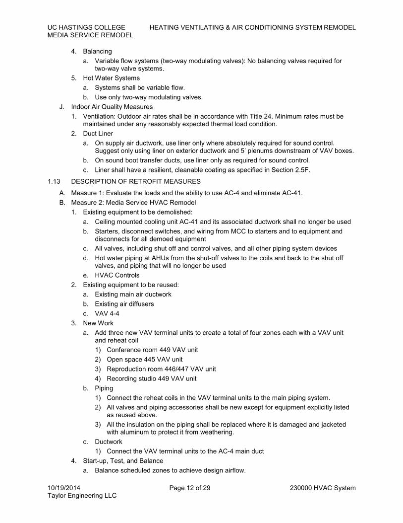
J. Indoor Air Quality Measures
1. Ventilation: Outdoor air rates shall be in accordance with Title 24. Minimum rates must be maintained under any reasonably expected thermal load condition.
2. Duct Liner
a. On supply air ductwork, use liner only where absolutely required for sound control. Suggest only using liner on exterior ductwork and 5’ plenums downstream of VAV boxes.
b. On sound boot transfer ducts, use liner only as required for sound control.
c. Liner shall have a resilient, cleanable coating as specified in Section 2.5F.
1.13 DESCRIPTION OF RETROFIT MEASURES
A. Measure 1: Evaluate the loads and the ability to use AC-4 and eliminate AC-41.
B. Measure 2: Media Service HVAC Remodel
1. Existing equipment to be demolished:
a. Ceiling mounted cooling unit AC-41 and its associated ductwork shall no longer be used
b. Starters, disconnect switches, and wiring from MCC to starters and to equipment and disconnects for all demoed equipment
c. All valves, including shut off and control valves, and all other piping system devices
d. Hot water piping at AHUs from the shut-off valves to the coils and back to the shut off valves, and piping that will no longer be used
e. HVAC Controls
2. Existing equipment to be reused:
a. Existing main air ductwork
b. Existing air diffusers
c. VAV 4-4
3. New Work
a. Add three new VAV terminal units to create a total of four zones each with a VAV unit and reheat coil
1) Conference room 449 VAV unit
2) Open space 445 VAV unit
3) Reproduction room 446/447 VAV unit
4) Recording studio 449 VAV unit
b. Piping
1) Connect the reheat coils in the VAV terminal units to the main piping system.
2) All valves and piping accessories shall be new except for equipment explicitly listed as reused above.
3) All the insulation on the piping shall be replaced where it is damaged and jacketed with aluminum to protect it from weathering.
c. Ductwork
1) Connect the VAV terminal units to the AC-4 main duct
4. Start-up, Test, and Balance
a. Balance scheduled zones to achieve design airflow.

UC HASTINGS COLLEGE HEATING VENTILATING & AIR CONDITIONING SYSTEM REMODEL
MEDIA SERVICE REMODEL
10/19/2014 Page 13 of 29 230000 HVAC System Taylor Engineering LLC
b. No hot water balancing required.
5. All other work required for a complete installation.
C. Measure 3: Calculate the load, air balance airflows and balance the IT open offices room 440.
1.14 ALTERNATES
A. Measure 2 Options
1. Alternate 2A: If the airflow capacity from AC-4 is not adequate, the new design can take advantage of the AC-41 to provide additional cooling to achieve the zoning as described in Measure 2.
a. Airflow capacity of AC-4 is considered as adequate if its design airflow rate is larger than the summation of existing peak airflow and total design airflow rate of the newly installed VAV terminal units Determination of existing peak airflow shall use one of the following methods. The methods are listed in an order of preference:
1) Analysis of the total supply airflow data for a design day. The total air flow can be obtained by summing up airflow of VAV boxes served by the unit.
2) Analysis of the actual supply fan speed and static pressure for a design days. Use the fan performance curve provided by the manufacture for a capacity analysis.
3) Obtain supply fan speed for a design days. Use the system balance report for a capacity analysis.
b. Add variable speed drive for AC-41
2. Alternate 2B: If AC-4 has enough airflow capacity, but only the main supply duct is undersized, there are three options:
a. Tap into the main duct where it is larger
b. Increase the size of the main duct
c. Add VAV terminal boxes, as required, connect to AC-41
1) Add variable speed drive for AC-41
PART 2 - MATERIALS
2.1 VARIABLE AIR VOLUME BOXES
A. Titus, Krueger, Trane, Metal Aire, Envirotech or equal
B. Maximum damper leakage at damper closure to be 3% of rated CFM at 2" static pressure
C. Maximum casing leakage: 7 cubic feet per minute leakage at 1.50 inches water column.
D. No cooling-only box requiring greater than 0.4 inches of total pressure drop at design air flows will be accepted. No greater than 0.5 inches total pressure drop shall be allowed for dual duct or reheat boxes. (Total pressure drop is static pressure drop plus velocity pressure drop.)
E. Provide access doors to all boxes for inspection of internal components such as dampers and reheat coil
F. Single duct: Titus DESV-30xx or equal
G. Digital Controls: See Section 250000.
2.2 AIR OUTLETS
A. Titus, Price, Krueger, Metal-Aire
B. Styles
1. General: Perforated face with deflector in neck (Titus PSS or equal with black interior) for all supply outlets, 2x2 perforated return grilles
2. Egg-crate grilles not acceptable in any location
C. Borders and Frames
1. Diffuser trim to match ceiling type; see reflected ceiling plans
2. Provide center-tees for slots in tee-bar ceilings

UC HASTINGS COLLEGE HEATING VENTILATING & AIR CONDITIONING SYSTEM REMODEL
MEDIA SERVICE REMODEL
10/19/2014 Page 14 of 29 230000 HVAC System Taylor Engineering LLC
3. Use frames with concealed fasteners; no visible screw heads
D. Interior of perforated diffusers (back-pan and blades) painted flat black
E. All visible portions of grille boxes painted flat black on the inside; grille box duct liner pins painted flat black
2.3 PIPE MATERIALS AND JOINING SYSTEMS
A. Piping materials shall be Type "L" Copper at contractor’s option.
B. Joint System
1. Copper
a. Hard temper
b. Wrought-copper, solder joint fittings, ANSI B16.22
c. 95/5 tin/antimony solder
2.4 PIPE FITTINGS & ACCESSORIES
A. Piping system components shall be selected for maximum design operating pressure based on static head, shutoff pump head, and pressure relief valve setting.
B. Shut-off Valves
1. Nibco or equal
2. Ball or butterfly valves only
3. Ball valves may be standard port
4. Butterfly valves used for balancing shall have:
a. Infinite position handles with memory stop
5. Butterfly valves shall have:
a. Removable seats
b. Valve stem shall be fastened to the disc so that no liquid can reach the stem
c. External fasteners such as roll pins, cotters, keys, or set screws will not be allowed
d. Butterfly valves shall be lug type; no wafer type
e. Provide manual gear operator for butterfly valves 8" and larger
6. Extended neck model for all insulated lines
7. Provide chain operators on all valves located higher than 7 feet above access level
C. Pipe Supports
1. Kin-line, Superstrut, or equal
2. Where pipe is insulated, protect insulation at hangers by installing a 22 gauge shield and clamp sized to allow pipe insulation to pass continuously through the hanger. For piping 2" and larger, provide 360 degree high density calcium silicate insert within shield.
2.5 DUCTWORK AND ACCESSORIES
A. Materials and Joints
1. Ductwork shall be galvanized sheet metal except as noted below
2. The gauge of metal, type of joints, hanging, reinforcing, and other details of construction shall conform to the SMACNA HVAC Duct Construction Standards.
3. Static pressure classes shall be as required by the fan system and acoustical requirements with the following minimums:
a. Medium pressure over occupied spaces: 2”
b. Low pressure downstream of VAV boxes: 1”
c. Transfer ducts and other ducts not connected to fans: 0.5”
4. Joints in Rectangular Sheet Metal Duct
a. Longitudinal seams shall be Pittsburgh.

UC HASTINGS COLLEGE HEATING VENTILATING & AIR CONDITIONING SYSTEM REMODEL
MEDIA SERVICE REMODEL
10/19/2014 Page 15 of 29 230000 HVAC System Taylor Engineering LLC
b. Transverse Joints:
1) Medium pressure ductwork shall be TDC, TDF or Duct-Mate
2) Low pressure ductwork shall be TDC, TDF or Duct-Mate except that ducts under 19" longest side may be "S" and drive
5. Fiberglass Duct: not allowed except for transfer ducts
6. Flexible Duct
a. Flexible duct shall be listed by UL under Class One air duct and UL 181. All flexible ducts, even low pressure ducts, shall be 4” pressure class to increase longevity.
b. Flexible duct length shall be not exceed 25 feet and shall be oversized as specified under Design Criteria. Ducts shall be supported as required by the CMC.
c. Flexible duct, other than acoustical flex duct, shall consist of a vinyl or zinc coated steel helix, solid liner and outer sheathing. Aluminum duct is also acceptable provided noise criteria can be met.
d. Flexible duct on supply systems shall include 1" fiberglass insulation.
e. Flexible duct shall not be used on medium pressure duct systems upstream of VAV box connections. (Hard duct connections to VAV boxes are required to improve inlet conditions to VAV box, reduce break-out noise, and to ensure that pressure drop is low.)
f. Final connections to all grilles shall be acoustical flex for final 10 feet where room permits.
g. Flex duct shall be installed with bends to maximize noise attenuation.
B. Duct Flexible Connectors
1. Duro Dyne Insulflex or equal
2. R=4.2
3. Factory attached to 3” wide metal on both sides of flexible material
4. Constructed in accordance with UL 181, Class I airduct with flanged connections
5. Flexible, neoprene-coated glass fabric not lighter than 30 oz/sq. yd.
6. All ducts shall be connected to fans with flexible duct connectors
C. Ductwork Sealing
1. Comply with:
a. Title 24 Energy Standards
b. UL 181, 181A and 181B
2. ALL Ductwork shall be sealed per SMACNA sealing classes as follows:
a. Seal class A
3. The gores of gored elbows and end caps shall be sealed.
4. Duct sealant shall be Fosters 32-14 "High Velocity Duct Sealant", Hardcast, or equal. Pressure applied tapes are not acceptable as the sole sealant.
5. Gasketted joints (e.g. TDC, TDF, and Duct-Mate) and longitudinal joints with sealant installed during fabrication do not require additional sealing.
6. Flexible ducts shall be connected using Panduit strap on the inner liner, sealed with tape, then the outer liner shall be sealed with tape.
D. Certainteed, Owens Corning, Manville, Knauf or equal
E. Insulation shall
1. Meet minimum thickness requirements of Chapter 2-53 of Title 24 and CMC 604.1
2. Meet mold, humidity, and erosion resistance requirements of CMC Standard 6-1
3. Have flame spread not more than 25 and smoke density of not more than 50 when tested as a composite installation per CMC 604.3
F. Ductwork
UC HASTINGS COLLEGE HEATING VENTILATING & AIR CONDITIONING SYSTEM REMODEL
MEDIA SERVICE REMODEL
10/19/2014 Page 16 of 29 230000 HVAC System Taylor Engineering LLC
1. In concealed space, including ceiling plenum: Shall be insulated with 1-1/2" Fiberglas, 3/4 lb./cubic-foot faced Duct Wrap.
2. Plenums at fan inlet and at fan and VAV box discharge, for acoustical attenuation: Shall be internally lined with Certainteed Toughgard Duct Liner, 1-1/2 lb. density, 1" thick.
3. Longitudinal joints shall be stapled. For rectangular ducts exceeding 24 inches, insulation on the bottom shall be additionally secured with adhesive.
G. Piping
1. Fiberglass molded pipe insulation with all service jacket.
2. Thickness per Title 24 requirements.
3. Fittings
a. Hot water: Fittings on pipe over 1/2" shall be insulated with fiberglass and finished with one piece PVC fitting cover (Zeston). Valves, flanges and irregular surfaces two inches and over shall be insulated with oversized pipe covering with ASJ jacket. Exposed ends shall be finished with four ounce canvas jacket saturated in Arabol.
2.6 ELECTRICAL WORK
A. All electrical materials and installation provided under this division shall comply with the requirements of the California Electrical Code.
B. Wiring in exposed areas (e.g. outdoors or in electrical and mechanical rooms) shall be in conduit. Plenum cable may be used for low voltage wiring above ceilings or in ductwork as allowed by code.
C. All control wiring shall be 120V and less. All wiring for voltages higher that 30 volts shall be installed by a licensed electrician.
PART 3 - EXECUTION
3.1 RECORD DRAWINGS
A. Keep an accurate dimensional record of installed systems and equipment. Maintain a set of record (“as-built”) drawings up-to-date as construction progresses. Drawings shall be maintained at the jobsite and available for inspection by the Engineer, and Owner’s representatives.
3.2 PROTECTION OF WORK DURING CONSTRUCTION
A. Protect from damage, water, dust, etc., material, equipment and apparatus provided under this Division, both in storage and installed, until Notice of Completion has been filed.
B. Provide protective covers, skids, plugs or caps to protect equipment and materials from damage and deterioration during construction. Protect exposed coils with plywood or other suitable rigid covers to avoid damage to fins.
C. Protect existing walls, doors, carpeting, etc. from damage. Any damage must be repaired at no cost to Owner.
D. Cover motors and other moving machinery to protect from dirt and water during construction.
E. Cover with plastic open ends of lined ductwork where exposed to weather.
F. Keep openings in piping closed to prevent entrance of foreign matter.
G. Material, Equipment or Apparatus:
1. Material, equipment or apparatus damaged because of improper storage or protection will be rejected.
2. Remove damaged material, equipment or apparatus from site and provide new, duplicate, material, equipment or apparatus in replacement of that rejected.
3. Porous materials, such as duct liner, shall be protected from weather. If such material becomes wet during construction, it shall be removed and replaced at no cost to Owner; drying is not sufficient due to possible microbial contamination.

UC HASTINGS COLLEGE HEATING VENTILATING & AIR CONDITIONING SYSTEM REMODEL
MEDIA SERVICE REMODEL
10/19/2014 Page 17 of 29 230000 HVAC System Taylor Engineering LLC
3.3 INSTALLATION AND WORKMANSHIP
A. All equipment and material shall be installed in a neat and workmanlike manner.
B. Repair all damaged or temporarily removed walls, roofs, roofing, equipment, etc.
C. Follow manufacturer’s installation instructions and recommendations.
D. All equipment must be anchored to the building. All hung equipment shall incorporate vibration isolation.
3.4 PIPING
A. Install pipes and pipe fittings in accordance with recognized industry practices which will achieve permanently leak resistant piping systems, capable of performing each indicated service without piping failure. Install each run with minimum joints and couplings but with adequate and accessible unions for disassembly and maintenance/replacement of valves and equipment. Reduce sizes where indicated by use of reducing fittings. Align piping accurately at connections, within 1/16-inch misalignment tolerance.
B. Escutcheons: Provide stainless steel escutcheons at piping penetrations of walls where exposed public view and required for proper appearance. Provide galvanized steel escutcheons at penetrations of masonry walls elsewhere. Escutcheons not generally required at drywall penetrations where not exposed to public view.
C. Application of Piping Accessories
1. This section establishes minimum requirements for installation of valves and other piping accessories. Additional devices may be installed as deemed necessary by the Contractor.
2. Test plugs
a. Inlet and outlet of all heat exchange devices including where fixed gauges are installed
b. At piping temperature sensor wells (for sensor calibration)
3. Coils
a. Isolation valves for each reheat coil
b. Test plugs at inlet and outlet reheat coil
c. Drains with ball valve and hose connection with cap
d. Control valves (provided by section 250000), with reducers as required
e. Balancing Valves (as required): See Paragraph 1.12I.4. Do not use balance valves as isolation valves unless valves have handles and memory stops.
3.5 DUCTWORK
A. Install per SMACNA Standards.
B. Rectangular and medium pressure duct bends greater than 45 degrees shall be curved sections, the center line radius of which shall not be less than 1-1/2 times the width of the duct in the plane of the bend. Where required due to space constraints, short radius elbows with duct splitter(s) may be used. No capped “bullhead” tees, and short-radius tees permitted. On low pressure ducts, square elbows with single width turning vanes may be used. Round duct elbows may be adjustable type on low pressure systems only, with gores sealed.
C. Grille Connections
1. Provide at entry to diffuser collar either:
a. Straight duct for 1 duct diameters or greater
b. Full radius elbow
c. Plenum with side duct collar
d. Equal to Thermaflex FlexFlow Elbow
2. Connections at grilles shall be insulated to the extent the duct is insulated including the final register box
3. Seal connections at grilles per seal class of upstream ductwork

UC HASTINGS COLLEGE HEATING VENTILATING & AIR CONDITIONING SYSTEM REMODEL
MEDIA SERVICE REMODEL
10/19/2014 Page 18 of 29 230000 HVAC System Taylor Engineering LLC
3.6 ELECTRICAL
A. All necessary and ancillary electrical work shall be include as part of this section including permits, design, disconnects and controls
3.7 SEISMIC CONTROL
A. Install seismic restraints for pipes, ducts and equipment per CBC and SMACNA or Mason Industries Guidelines for pipe and duct bracing.
B. Design and provide restraints to prevent permanent displacement in any direction caused by lateral motion, overturning, or uplift:
1. Calculations required for supports and bracing for situations not covered by referenced guidelines.
2. Include horizontal and vertical reaction loads at connections to building structures for all seismic restraints, including those covered by referenced guidelines. Coordinate reaction loads and attachment details with structural engineer for building.
3. Calculations made and signed by registered structural engineer knowledgeable in seismic design:
a. Hired under this Section of work
b. Cost of calculations borne under this Section
C. Provide resilient restraining devices as required to prevent equipment motion in excess of 1/4 inch
D. Coordinate seismic bracing requirements with other sections to result in:
1. Vertical pipe and duct restraints to coincide with and take place of required hangers
2. Longitudinal pipe bracing to coincide with required pipe anchors
E. Bracing shall not short circuit vibration isolation systems or transmit objectionable vibration or noise
3.8 CLEANING
A. Thoroughly clean all equipment, ducts, etc. free of dust, scale, filings, plaster, grease, oil, paint and other construction debris.
B. No construction materials, debris, dirt, etc. shall remain in any area, including both tenant areas and mechanical areas, during normal business hours. Clean up all areas prior to start of normal business hours.
C. Water systems
1. All open circuit systems shall be flushed until water runs clean.
2. Closed circuit systems
a. Drain water through new branch piping to eliminate construction debris.
b. Refilled with clean water.
c. Supplement chemical inhibitors per recommendations of building’s water quality service company.
D. Ducts
1. Vacuum any visible debris from inside ducts, duct plenums and grille boxes.
2. Use connected fan(s) to blow air through all duct systems until they are free of all foreign materials.
E. Post-construction purge
1. Operate all systems 24 hours per day in normal occupied mode for a minimum of 30 days after installation of furnishings.
2. Return system to normal schedules after purge period.

UC HASTINGS COLLEGE HEATING VENTILATING & AIR CONDITIONING SYSTEM REMODEL
MEDIA SERVICE REMODEL
10/19/2014 Page 19 of 29 230000 HVAC System Taylor Engineering LLC
3.9 EQUIPMENT AND PIPING IDENTIFICATION
A. Equipment
1. All mechanical equipment shall be identified by nameplates securely fastened in a clearly visible location to the equipment housing or frame. Nameplates shall include the equipment design plan mark and brief description of the area or system served, such as: "VAV 4-4: CONFERENCE ROOM 449". Provide additional nameplates on face of starters or variable speed drives provided under this Section.
2. Nameplates shall be 2-1/2" x 3/4" minimum, either 1/6" thick Bakelite with engraved white core letters and beveled edge, or aluminum with black enameled background and etched or engraved natural aluminum lettering.
3. Manufacturer's nameplate shall be clean and legible and installed in a clearly visible location.
B. Piping
1. Identify piping with symbol identification (e.g. HWS) and direction of flow arrows, complying with ANSI A 13.1 color standards.
2. Identify piping at approximately 25' centers where unconcealed Concealed piping above inaccessible ceilings shall be identified at each access panel. Concealed piping above accessible ceilings shall be identified within 10 feet of each wall penetration (both sides of walls).
3. Where capped piping is provided for future connections, provide legible and durable metal tags indicating symbol identification.
4. Printed labels with colored background and attaching strap: Seton, W. Brady, or equal.
C. Valves: Tags not required
3.10 PAINTING
A. Painting Under this Section
1. Interior of ductwork at air outlets as far back as visible from occupied spaces
a. Flat black
2. Marred surfaces of factory painted equipment
a. Spot coat to match adjacent coat
B. Execution
1. Protect flooring and equipment with drip cloths
2. Paint and materials stored in location where directed
3. Oily rags and waste removed from building every night
4. Wire brush and clean off all oil, dirt and grease areas to be painted before paint if applied
5. Workmanship
a. No painting or finishing shall be done with:
1) Dust laden air
2) Unsuitable weather conditions
3) Space temperature below 60 degrees F
b. Pipes painted containing no heat and remain cold until paint is dried
c. Paint spread with uniform and proper film thickness showing no runs, sags, crawls or other defects
d. Finished surfaces shall be uniform in sheen, color, and texture
e. All coats thoroughly dry before succeeding coats are applied, minimum 24 hours between coats
f. Priming undercoat of slightly different color for inspection purposes
6. Piping continuously painted in all exposed areas
C. Paint

UC HASTINGS COLLEGE HEATING VENTILATING & AIR CONDITIONING SYSTEM REMODEL
MEDIA SERVICE REMODEL
10/19/2014 Page 20 of 29 230000 HVAC System Taylor Engineering LLC
1. High gloss medium or long alkyd paint
2. Best grade for its purpose
3. Deliver in original sealed containers
4. Apply in accordance with manufacturer’s instructions
D. Colors
1. Color coding as follows on Sherwin Williams, "Kem Lustral" or "Metalalistic II" name and figure numbers
2. Interior of ductwork as far back as visible from outside: flat black
3. Uncoated hangers, supports, rods and insets: dip in zinc chromate primer
E. Factory Finish
1. Steel air outlets in acoustical tile ceilings: baked white enamel
2. Aluminum air outlets: anodized
3. Exposed fan coil units: baked enamel
4. Unit ventilators and unit heaters: baked enamel
F. Marred surfaces of prime coated equipment and piping: spot prime coat to match adjacent coat
3.11 LEAKAGE TESTING
A. Testing of hydronic systems: Pressure test piping at 1-1/2 times operating pressure, hold for one hour. No loss in pressure will be permitted. All leaks shall be repaired by tightening, rewelding or replacing pipe and fittings. Caulking of joints will not be permitted. Retest as required.
B. Duct leakage testing: Duct leakage tests are not required but the Owner may elect to conduct one at his cost. If tests are performed, they shall be in accordance with the SMACNA Duct Leakage Testing Manual. If duct systems do not meet the leakage classes listed in this manual at applicable duct rating pressure, leaks shall be sealed and tests rerun, both at the HVAC contractor's expense.
3.12 TESTING, ADJUSTING, AND BALANCING
A. Test and adjust all items of heating, ventilating and air conditioning system to provide design conditions:
1. Testing and balancing shall be performed in complete accordance with AABC or NEBB National Standards for Field Measurements and Instrumentation as applicable to air distribution and hydronic systems.
2. In general, systems shall be balanced so that one or more balancing valves/dampers remains wide open; if further flow reduction is required, fan or pump speed shall be reduced or impellers trimmed (in the case of pumps).
3. Air Systems
a. Test and adjust each air outlet and intake to within 10% of design requirements.
b. Each grille, diffuser and register shall be identified as to locations and area. Size, type and manufacturer of diffusers, grilles, and registers shall be identified and listed. Readings and tests of diffusers, grilles, and registers shall include design, initial test, and final adjusted FPM velocity and CFM.
c. Total air quantities for all air-handling units shall be determined by pitot tube traverse of main ducts, traverse of filter banks or coils, and by totaling the readings of individual air outlets. All three methods should be employed where possible so that comparisons can be made.
d. Total air quantities shall be obtained by adjustment of fan speeds. The HVAC contractor shall include the costs of dampers, pulley and belt changes in his contract.
e. Test and adjust scheduled airflows to each VAV box within 10% of design requirements.
f. Minimum outside air quantities shall be established by pitot tube traverse of outside air duct or louver, or by deduction from pitot traverse of return air and outside air ducts.

UC HASTINGS COLLEGE HEATING VENTILATING & AIR CONDITIONING SYSTEM REMODEL
MEDIA SERVICE REMODEL
10/19/2014 Page 21 of 29 230000 HVAC System Taylor Engineering LLC
Balance by measurement of return air, outside air, and mixed air temperatures shall NOT be used due to inherent inaccuracy.
1) For variable air volume systems, the outside air must be reset for the fan range to meet minimum outside air requirements.
a) Two outside air settings are required:
(1) At design airflow
(2) With all VAV boxes at minimum airflow
b) Coordinate with controls contractor for the two outside air readings so the controls contractor can record the required damper signal at each outside air damper position. See Controls for outside air damper reset control.
g. For variable air volume systems, the air balancer shall work with the controls contractor to determine the minimum static pressure setpoint required to satisfy the hydraulically most remote VAV box. Arbitrarily setting VAV fan static pressure setpoints shall not be satisfactory.
4. Hydronic Systems
a. General
1) Variable flow systems: Water-side flow balance of two-way valve (variable flow) systems is not required except to ensure that water flow occurs properly at each terminal and to take entering and leaving conditions.
b. Under no circumstances shall valves at pumps be used for balance. All balance shall be done using valves at coils, chillers, and other devices served by the pumps.
c. Test and adjust entering and leaving flows at primary equipment, heat exchangers and coils. Test documentation shall include design, initial test and final adjusted GPM. Balancing valves shall be permanently marked after balance is complete so that they can be restored to their correct positions if disturbed.
d. Hydronic balance shall be performed after air quantities have been set so that the heat gain (or loss) in the air can be compared with heat loss (or gain) in the water.
5. Provide upon completion of running tests, two (2) complete sets of data listed below for all items of equipment for incorporation in Owner's Operation and Maintenance Manual for the job:
a. Name and address of testing agency and name of individual responsible for the work
b. Make, model and latest calibration date of testing equipment
c. Sketch or written description sufficient to identify individual devices tested
d. Final air quantities at each air outlet and inlet and maximum and minimum air flows for each VAV box
e. Final air quantities and static pressures at each piece of air handling equipment
f. Entering and leaving water pressures, flow rates, and test temperatures at each piece of hydronic equipment
g. Manufacturer, size, model, serial number, motor hp, rpm, voltage, full load amps, vee belt sheave sizes, grooves, belts, sizes, length, starter heater size, rating and fuse size of each fan and pump.
3.13 COMMISSIONING
A. Commissioning (Cx) activities shall be coordinated by a representative of the HVAC Contractor who shall serve as the Commissioning Coordinator (CxC).
B. The commissioning responsibilities of the HVAC Contractor are as follows:
1. Include requirements for submittal data, commissioning documentation, O&M data and training.
2. Attend a commissioning scoping meeting, assist in commissioning schedule development and other meetings necessary to facilitate the Cx process.

UC HASTINGS COLLEGE HEATING VENTILATING & AIR CONDITIONING SYSTEM REMODEL
MEDIA SERVICE REMODEL
10/19/2014 Page 22 of 29 230000 HVAC System Taylor Engineering LLC
3. Attend regular commissioning meetings during the start-up, pre-functional test and functional test periods as scheduled by the CxC.
4. Assist and cooperate with the TAB contractor by putting all HVAC equipment and systems into operation and continuing the operation during each working day of TAB and commissioning, as required.
5. Develop and complete pre-functional checklists and submit for review.
6. Develop a full start-up and initial checkout plan and schedule using manufacturer’s and specified start-up procedures for all commissioned equipment. Submit for review and approval prior to startup.
7. Provide skilled technicians to execute starting and pre-functional testing of equipment, and to assist in executing functional performance tests and interpret the data, as necessary. Ensure that they are available and present during the agreed upon schedules and for sufficient duration to complete the necessary tests, adjustments and problem-solving.
8. Develop functional performance test procedures to fully test all HVAC control sequences. Submit to Owner for review and approval.
9. Perform functional tests, retesting until all are satisfactorily complete, and complete test forms. Submit to Owner for review and approval.
10. Prepare an outline and schedule for training programs for approval.
11. Include start up, pre-functional, and functional test documentation in the Operations and Maintenance Manual.
C. Equipment
1. HVAC Contractor shall provide all test equipment necessary to fulfill the testing requirements of this Division.
2. The contractor shall provide all standard testing equipment required to perform pre-functional tests, startup, and required functional performance testing.
3. The contractor shall provide two-way radios to facilitate communications during commissioning.
4. All testing equipment shall be of sufficient quality and accuracy to test and/or measure system performance within the specified tolerances. All equipment should be calibrated according to the manufacturer’s recommended intervals.
D. Controls Commissioning
1. Calibration: Factory calibration is acceptable. Obviously inaccurate sensors must be replaced if calibration is not possible.
2. Each control loop shall be tuned as required to maintain setpoint within specified accuracy requirements during normal operating conditions and to achieve this stability within 15 minutes after an abrupt system or setpoint change.
3. Each digital output point shall be tested to ensure the controlled device starts and stops properly. Each digital input status point shall be tested to ensure the input device is properly adjusted (e.g. adjust current setpoint on current switches) and wired.
4. Each control sequence shall be tested for proper operation. Trend logs shall be collected during the test period accordingly.
5. Maintain a test log of all testing and calibration.
E. Functional Tests
1. Summary
a. Functional testing is performed to verify proper operation of the mechanical systems, rather than just the verification of each component. The objective of the functional performance testing is to demonstrate that each system is operating according to the documented design intent and contract documents. Functional testing facilitates bringing the systems from a state of substantial completion to full dynamic operation. Additionally,

UC HASTINGS COLLEGE HEATING VENTILATING & AIR CONDITIONING SYSTEM REMODEL
MEDIA SERVICE REMODEL
10/19/2014 Page 23 of 29 230000 HVAC System Taylor Engineering LLC
during the testing process, areas of deficient performance are identified and corrected, improving the operation and functioning of the systems.
b. Each system shall be operated through all modes of operation where there is a specified system response. Verification of each sequence in the sequence of operation is required. Proper responses to such modes and conditions shall also be tested.
2. Prerequisites
a. All pre-functional testing must be successfully completed before beginning functional testing, see pre-functional test forms below.
b. All HVAC equipment must be successfully started, and Testing, Adjusting, and Balancing work completed before beginning functional testing.
c. Calibration and Loop Tuning must be successfully completed before any functional testing can begin.
d. All systems should be running according to normal sequence of operations unless commanded otherwise as part of functional testing.

UC HASTINGS COLLEGE HEATING VENTILATING & AIR CONDITIONING SYSTEM REMODEL
MEDIA SERVICE REMODEL
10/19/2014 Page 24 of 29 230000 HVAC System Taylor Engineering LLC
Air Handling Unit Pre-Functional Test Data Sheet
AHU Tag ________
Air Handling Units and Coils Data
As designed As found Action required Done
Manufacturer Model number Serial number Nameplate airflow Cooling coil rows/fins Heating coil rows/fins Filters: qty / type / size
Indoor Fan Data
Quantity Drive Type DD , Belt DD , Belt
Wheel type propeller , FC
BI , AF propeller , FC
BI , AF
Motor Type ODP , TEFC ODP , TEFC HP/RPM Volts/phase Nameplate efficiency
Indoor Fan Motor Variable Speed Drive Data (if applicable)
Manufacturer Model number Serial number Manual bypass yes , no yes , no
Installation
As found Action required Done
Vibration isolation adjusted yes , no , n/a
Shipping blocks removed yes , no , n/a Air handling unit fan & motor installed and mounted properly and rotate freely
yes , no , n/a
Motor and drive aligned and tight yes , no , n/a
Belt guard installed yes , no , n/a Fan motors lubricated yes , no , n/a Condensate drain piping installed with trap yes , no , n/a Filters installed with no air gaps yes , no , n/a Filter pressure gage installed yes , no , n/a Duct complete and sealed yes , no , n/a Ducts connected properly with flexible duct connections per drawings
yes , no , n/a
Duct supported independently from fan yes , no , n/a Inlet/discharge dampers installed correctly yes , no , n/a Piping complete and tested yes , no , n/a Pipe connected correctly at coils and supported independently from air handling units
yes , no , n/a
Coil fins combed or not damaged yes , no , n/a Vents and drains installed per drawings yes , no , n/a Electrical connections complete & tight yes , no Disconnect switch installed yes , no Control gages and tubing connected per drawings yes , no , n/a

UC HASTINGS COLLEGE HEATING VENTILATING & AIR CONDITIONING SYSTEM REMODEL
MEDIA SERVICE REMODEL
10/19/2014 Page 25 of 29 230000 HVAC System Taylor Engineering LLC
Air Handling Units and Coils Data
Controls and interlock completed per drawings yes , no , n/a Sign Off
As found checked by Date Remedial action checked by Date

UC HASTINGS COLLEGE HEATING VENTILATING & AIR CONDITIONING SYSTEM REMODEL
MEDIA SERVICE REMODEL
10/19/2014 Page 26 of 29 230000 HVAC System Taylor Engineering LLC
Duct System Addition Pre-Functional Test Data Sheet
Duct System Name ___________
Duct System Data
As designed As found/tested Action required Done
Duct material Insulation wrap material Insulation wrap thickness Insulation lining material Insulation lining thickness
Installation
As found Action required Done
Spring hangers where specified yes , no , n/a
Seismic supports installed per spec’s yes , no , n/a Longitudinal duct joints sealed yes , no Transverse duct joints sealed yes , no Duct penetrations sealed yes , no Duct insulation completed and vapor barriers sealed yes , no , n/a Flexible duct connections installed properly yes , no , n/a Flexible ducts installed with no kinks yes , no , n/a Duct pressure tests performed and passed yes , no , n/a Duct leakage tests performed and passed yes , no , n/a
Sign Off
As found checked by Date Remedial action checked by Date

UC HASTINGS COLLEGE HEATING VENTILATING & AIR CONDITIONING SYSTEM REMODEL
MEDIA SERVICE REMODEL
10/19/2014 Page 27 of 29 230000 HVAC System Taylor Engineering LLC
Air Terminal Unit (VAV Box) Pre-Functional Test Data Sheet
Air Terminal Unit Tag _______
Air Terminal Units Data
As designed As found Action required Done
Manufacturer Model number / size Serial number
Reheat Coil Data
Rows Installation
As found Action required Done
Shipping blocks removed yes , no , n/a
Duct complete and sealed yes , no , n/a Duct supported independently from air terminal units yes , no , n/a Inlet duct straight for proper length yes , no , n/a Piping & insulation complete and tested yes , no , n/a Piping supported independently from air terminal units yes , no , n/a Piping valve & fitting train as spec’d yes , no , n/a Controls connected and wired yes , no , n/a Damper actuator mounted and wired yes , no , n/a Hot water valve actuator mounted and wired yes , no , n/a
Sign Off
As found checked by Date Remedial action checked by Date

UC HASTINGS COLLEGE HEATING VENTILATING & AIR CONDITIONING SYSTEM REMODEL
MEDIA SERVICE REMODEL
10/19/2014 Page 28 of 29 230000 HVAC System Taylor Engineering LLC
3. Procedure
a. Functional tests shall be conducted by the Controls Contractor with the assistance of the HVAC Contractor, witnessed by the CxC.
b. Functional test forms shall be submitted to the Owner for review and approval.
c. Demonstration tests: A subset of functional tests selected by the Owner shall be performed by the Controls Contractor and witnessed by the Owner’s representatives. The test period shall not exceed 1/2 days.
F. Trend Reviews
1. Contractor shall initiate trends of all real and relevant software points on a 5 minute basis (or COV for digital points).
2. Following successful completion of functional tests, a minimum of two weeks of trend data shall be collected and submitted to the Owner for review and approval. Data shall be in electronic format such as CSV, Excel, Access, or SQL.
3. If any but very minor glitches are indicated in the trends, the verification period will start over until there are two continuous weeks of error free operation. Contractor shall reimburse Owner’s representative at normal billing rates for all time spent reviewing trend reviews after the first set.
4. Final payment and system acceptance will only be made if the trend reviews indicate proper system operation.
G. Training
1. General Training: Upon completion of work, provide Owner's operating personnel two instruction periods in operation and maintenance of material and equipment. Each period shall be 2-hours continuous; first period to be immediately upon completion, and second period within 30 days of completion.
2. Control System Training: Upon completion of all commissioning work, provide Owner's operating personnel three instruction periods in operation of control system. Each period shall be 2-hours continuous; first period to be immediately upon completion, second period within 30 days of completion, and third period just prior to the end of the warranty period.
END OF SECTION

UC HASTINGS COLLEGE HEATING VENTILATING & AIR CONDITIONING SYSTEM REMODEL
MEDIA SERVICE REMODEL
10/19/2014 Page 29 of 29 230000 HVAC System Taylor Engineering LLC
BID FORM
UC Hastings Media Service Remodel
Date
Company
Salesperson
Title
This proposal includes all bid documents through Addendum
The Bidder agrees to bring the Work to Substantial Completion from the Notice to Proceed within this number of weeks
Description Bid Price
Measures: HVAC Upgrade Price Breakdown
Measure 1: Evaluate the loads and the ability to use AC-4 and eliminate AC-41. $
Measure 2: Media Service HVAC work $
Measure 2: Controls remodel work $
Measure 3: Load calculations and balance Room 440 HVAC work $
Measure 3: Load calculations and balance Room 440 Controls work $
Total HVAC Upgrade $
Alternate 2A: Reuse AC41 $ Alternate 2B: Reconfigure AC-4 main ductwork $ Contractor Alternate 1: _______________ $ Contractor Alternate 2: _______________ $
Change-order markup (combined overhead and profit) %
Exclusions not listed in specifications:

UC HASTINGS COLLEGE HEATING VENTILATING & AIR CONDITIONING SYSTEM REMODEL
MEDIA SERVICE REMODEL
10/19/2014 Page 1 of 87 250000 Building Automation System Taylor Engineering LLC
UC HASTINGS MEDIA SERVICE REMODEL
SECTION 250000 BUILDING AUTOMATION SYSTEMS
PART 1 GENERAL
1.1 SUMMARY
Furnish and install a digital Building Automation System (BAS). The systems to be controlled or monitored under work of this Section include but are not limited to the following:
1. HVAC Systems
2. Integrate into the existing Trane Summit system and Trane Tracer software including graphical display and programming from the existing building front end graphical user interface
Coordination with other Divisions: See coordination matrix in Section 230000 Heating Ventilating & Air Conditioning System.
1.2 REFERENCE STANDARDS
Nothing in Contract Documents shall be construed to permit Work not conforming to applicable laws, ordinances, rules, and regulations. When Contract Documents differ from requirements of applicable laws, ordinances, rules and regulations, comply with documents establishing the more stringent requirement.
The latest published or effective editions, including approved addenda or amendments, of the following codes and standard shall apply to the BAS design and installation as applicable.
State, Local, and City Codes
CBC − California Building Code
CMC − California Mechanical Code
CEC – California Electrical Code
San Francisco City and County Codes
American Society of Heating, Refrigeration and Air Conditioning Engineers (ASHRAE)
ANSI/ASHRAE 135 – BACnet - A Data Communication Protocol for Building Automation and Control Networks.
ANSI/ASHRAE Standard 15 – Safety Standard for Refrigeration Systems.
Electronics Industries Alliance
EIA-232 – Interface Between Data Terminal Equipment and Data Circuit-Terminating Equipment Employing Serial Binary Data Interchange.
EIA-458 – Standard Optical Fiber Material Classes and Preferred Sizes.

UC HASTINGS COLLEGE HEATING VENTILATING & AIR CONDITIONING SYSTEM REMODEL
MEDIA SERVICE REMODEL
10/19/2014 Page 2 of 87 250000 Building Automation System Taylor Engineering LLC
EIA-485 – Standard for Electrical Characteristics of Generator and Receivers for use in Balanced Digital Multipoint Systems.
EIA-472 – General and Sectional Specifications for Fiber Optic Cable.
EIA-475 – Generic and Sectional Specifications for Fiber Optic Connectors and all Sectional Specifications.
EIA-573 – Generic and Sectional Specifications for Field Portable Polishing Device for Preparation Optical Fiber and all Sectional Specifications.
EIA-590 – Standard for Physical Location and Protection of Below-Ground Fiber Optic Cable Plant and all Sectional Specifications.
Underwriters Laboratories
UL 916 – Energy Management Systems.
National Electrical Manufacturers Association
NEMA 250 – Enclosure for Electrical Equipment.
Institute of Electrical and Electronics Engineers (IEEE)
IEEE 142 – Recommended Practice for Grounding of Industrial and Commercial Power Systems.
IEEE 802.3 – CSMA/CD (Ethernet – Based) LAN.
IEEE 802.4 – Token Bus Working Group (ARCNET – Based) LAN.
1.3 DEFINITIONS
Acronyms
AAC Advanced Application Controller
AH Air Handler
AHU Air Handling Unit
AI Analog Input
ANSI American National Standards Institute
AO Analog Output
ASC Application Specific Controllers
ASCII American Standard Code for Information
Interchange
ASHRAE American Society of Heating, Refrigeration and Air Conditioning Engineers
ASME American Society of Mechanical Engineers
ASTM American Society for Testing and Materials
A-to-D Analog-to-Digital
BACnet Data Communications Protocol for Building Automation and Control Systems
BC Building Controller
BIBB BACnet Interoperability Building Blocks
BTL BACnet Testing Laboratory
CAD Computer Aided Drafting

UC HASTINGS COLLEGE HEATING VENTILATING & AIR CONDITIONING SYSTEM REMODEL
MEDIA SERVICE REMODEL
10/19/2014 Page 3 of 87 250000 Building Automation System Taylor Engineering LLC
CHW Chilled Water
CHWR Chilled Water Return
CHWS Chilled Water Supply
COV Change of Value
CSS Control Systems Server
CU Controller or Control Unit
CV Constant Volume
CW Condenser Water
CWR Condenser Water Return
CWS Condenser Water Supply
DBMS Database Management System
DDC Direct Digital Control
DHW Domestic Hot Water
DI Digital Input
DO Digital Output
D-to-A Digital-to-Analog
BAS Building Automation System
EMT Electrical Metallic Tubing
EP Electro-Pneumatic
ETL Edison Testing Laboratories
GUI Graphical User Interface
HHD Hand Held Device
HOA Hand-Off-Automatic
HVAC Heating, Ventilating and Air-Conditioning
HTTP Hyper-Text Transfer Protocol
I/O Input/output
IEEE Institute of Electrical and Electronics Engineers
ISO International Organization for Standardization
LAN Local Area Network
LANID LAN Interface Device
LCP Lighting Control Panel
MAC Medium Access Control
MHz Megahertz
MS/TP Master-Slave/Token-Passing
NEMA National Electrical Manufacturers Association
NFPA National Fire Protection Association
NIST National Institute of Standards and Technology
ODBC Open Database Connectivity
OI Operator Interface
OWS Operator Workstation
P Proportional
PC Personal Computer
PI Proportional-Integral
PICS Protocol Implementation Conformance Statement
PID Proportional-Integral-Derivative
POT Portable Operators Terminal
PTP Point-to-Point
RAM Random Access Memory
SOO Sequence of Operation
SQL Standardized Query Language
SSL Secure Socket Layers

UC HASTINGS COLLEGE HEATING VENTILATING & AIR CONDITIONING SYSTEM REMODEL
MEDIA SERVICE REMODEL
10/19/2014 Page 4 of 87 250000 Building Automation System Taylor Engineering LLC
TAB Test, Adjust, and Balance
TDR Time Delay Relay
UFT Underfloor Fan Terminal Box
UL Underwriters’ Laboratories, Inc.
XML Extensible Markup Language
Terms
Term Definition
Accessible Locations that can be reached with no more than a ladder to assist access and without having to remove permanent partitions or materials. Examples include inside mechanical rooms, mechanical equipment enclosures, instrument panels, and above suspended ceilings with removable tiles.
BACnet Interoperability Building Blocks
A BIBB defines a small portion of BACnet functionality that is needed to perform a particular task. BIBBs are combined to build the BACnet functional requirements for a device in a specification.
BACnet/BACnet Standard
BACnet communication requirements as defined by the latest version of ASHRAE/ANSI 135 and approved addenda.
Change of Value An event that occurs when a digital point changes value or an analog value changes by a predefined amount.
Client A device that is the requestor of services from a server. A client device makes requests of and receives responses from a server device.
Concealed Embedded in masonry or other construction, installed in furred spaces, within double partitions, above hung ceilings, in trenches, in crawl spaces, or in enclosures.
Continuous Monitoring A sampling and recording of a variable based on time or change of state (such as trending an analog value, monitoring a binary change of state).
Contract Documents Specifications, drawings, and other materials provided with request for bids.
Control Systems Server A computer(s) that maintain(s) the systems configuration and programming database.
Controller Intelligent stand-alone control device. Controller is a generic reference to BCs, AACs, and ASCs.
Direct Digital Control Microprocessor-based control including Analog/Digital conversion and program logic.
Building Automation System
The entire integrated management and control system.
Equal Approximately equal in material types, weight, size, design, quality, and efficiency of specified product.
Exposed Not installed underground or concealed.
Furnish To purchase, procure, acquire and deliver complete with related accessories.
Gateway Bi-directional protocol translator connecting control systems that use different communication protocols.

UC HASTINGS COLLEGE HEATING VENTILATING & AIR CONDITIONING SYSTEM REMODEL
MEDIA SERVICE REMODEL
10/19/2014 Page 5 of 87 250000 Building Automation System Taylor Engineering LLC
Term Definition
Hand Held Device Manufacturer’s microprocessor based portable device for direct connection to a field Controller.
Inaccessible Locations that do not meet the definition of accessible. Examples include inside furred walls, pipe chases and shafts, or above ceilings without removable tiles.
Indicated, shown or noted
As indicated, shown or noted on drawings or specifications.
Install To erect, mount and connect complete with related accessories.
Instrumentation Gauges, thermometers and other devices mounted in ductwork or piping that are not a part of the BAS.
IT LAN Reference to the facility’s Information Technology network, used for normal business-related e-mail and Internet communication.
LAN Interface Device Device or function used to facilitate communication and sharing of data throughout the BAS.
Local Area Network Computer or control system communications network limited to local building or campus.
Master-Slave/Token Passing
Data link protocol as defined by the BACnet standard.
Motor Controllers Starters, variable speed drives, and other devices controlling the operation of motors.
Native BACnet Device A device that uses BACnet for communication. A device may also provide gateway functionality and still be described as a Native BACnet device.
Native BACnet System A network composed only of Native BACnet Devices without gateways.
Open Database Connectivity
An open standard application-programming interface for accessing a database developed. ODBC compliant systems make it possible to access any data from any application, regardless of which database management system is handling the data.
Open Connectivity OPC is an interoperability standard developed for industrial applications. OPC compliant systems make it possible to access or exchange data from any application, regardless of which database management system is handling the data.
Operator Interface A device used by the operator to manage the BAS including OWSs, POTs, and HHDs.
Operator Workstation The user’s interface with the BAS system. As the BAS network devices are stand-alone, the OWS is not required for communications to occur.
Owner The Owner or their designated representatives.
Piping Pipe, tube, fittings, flanges, valves, controls, strainers, hangers, supports, unions, traps, drains, insulation and related items.
Points All physical I/O points, virtual points, and all application program parameters.

UC HASTINGS COLLEGE HEATING VENTILATING & AIR CONDITIONING SYSTEM REMODEL
MEDIA SERVICE REMODEL
10/19/2014 Page 6 of 87 250000 Building Automation System Taylor Engineering LLC
Term Definition
Point-to-Point Serial communication as defined in the BACnet standard.
Portable Operators Terminal
Laptop PC used both for direct connection to a controller and for remote dial up connection.
Primary Controlling LAN High speed, peer-to-peer controller LAN connecting BCs and optionally AACs and ASCs.
Protocol Implementation Conformance Statement
A written document that identifies the particular options specified by BACnet that are implemented in a device.
Provide Furnish, supply, install and connect up complete and ready safe and regular operation of particular work referred to unless specifically noted.
Reviewed, approved, or directed
Reviewed, approved, or directed by or to Owner’s Representative.
Router A device that connects two or more networks at the network layer.
Secondary Controlling LAN
LAN connecting AACs and ASCs.
Server A device that is a provider of services to a client. A client device makes requests of and receives responses from a server device.
Standardized Query Language
SQL - A standardized means for requesting information from a database.
Supervisory LAN Ethernet-based LAN connecting Primary Controller LANs with each other and OWSs, CSS, and THS. See System Architecture below.
Supply Purchase, procure, acquire and deliver complete with related accessories.
Wiring Raceway, fittings, wire, boxes and related items.
Work Labor, materials, equipment, apparatus, controls, accessories and other items required for proper and complete installation.
1.4 QUALITY ASSURANCE
Materials and Equipment
Manufacturer’s Qualifications: See 2.1 for approved manufacturers.
Product Line Demonstrated History: The direct digital control equipment product line being proposed for the Project must have an installed history of demonstrated satisfactory operation for a length of one year since date of final completion in at least 10 installations of comparative size and complexity.
All products used in this Project installation shall be new, currently under manufacture, and shall have been available from the manufacturer for a minimum of 6 months prior to date of proposal and previously installed and proven effective in installations of similar nature, not including test sites. This installation shall not be used as a test site for any new products unless explicitly approved by the Owner in writing. Spare parts shall be available for at least five years after completion of this contract.

UC HASTINGS COLLEGE HEATING VENTILATING & AIR CONDITIONING SYSTEM REMODEL
MEDIA SERVICE REMODEL
10/19/2014 Page 7 of 87 250000 Building Automation System Taylor Engineering LLC
All BACnet devices must either be certified as complaint with the BACnet standard through a listing by the BACnet Testing Laboratory (BTL) or the vendor must supply proof of having submitted the device for testing by BTL.
The BAS and components shall be listed by Underwriters Laboratories UL 916 as an Energy Management System.
Manufacturer shall be ISO 9001 registered.
Installer
BAS Contractor’s Project Manager Qualifications: Individual shall specialize in and be experienced with direct digital control system installation for not less than 3 years. Project Manager shall have experience with the installation of the proposed direct digital control equipment product line for not less than 2 projects of similar size and complexity. Project Manager must have proof of having successfully completed the most advanced training offered by the manufacturer of the proposed product line.
BAS Contractor’s Programmer Qualifications: Individual(s) shall specialize in and be experienced with direct digital control system programming for not less than 3 years and with the proposed direct digital control equipment product line for not less than 1.5 years. Programmers must show proof of having successfully completed the most advanced programming training offered by the vendor of the programming application on the proposed product line.
BAS Contractor’s Service Qualifications: The installer must be experienced in control system operation, maintenance and service. BAS Contractor must document a minimum 5-year history of servicing installations of similar size and complexity. Installer must also document at least a 1-year history of servicing the proposed product line.
Installer’s Response Time and Proximity
Installer must maintain a fully capable service facility within 50 miles of the subject Project. Service facility shall manage the emergency service dispatches and maintain the inventory of spare parts.
Installer must demonstrate the ability to meet the emergency response times listed in Paragraph 1.10B.
Electrical installation shall be by manufacturer-trained electricians
Exception: Roughing in wiring and conduit and mounting panels may be subcontracted to any licensed electrician.
1.5 SUBMITTALS
No work may begin on any segment of this Project until the related submittals have been reviewed for conformity with the design intent and the Contractor has responded to all comments to the satisfaction of the Owner’s Representative.
Submit drawings and product data as hereinafter specified. Conditions in this Section take precedence over conditions in Division 1.
Submittal Schedule: Submittal schedule shall be as follows unless otherwise directed by the Owner’s Representative:

UC HASTINGS COLLEGE HEATING VENTILATING & AIR CONDITIONING SYSTEM REMODEL
MEDIA SERVICE REMODEL
10/19/2014 Page 8 of 87 250000 Building Automation System Taylor Engineering LLC
Allow 10 working days for approval, unless Owner’s Representative agrees to accelerated schedule.
Submittal Package 0 (Qualifications) shall be submitted with bid.
Submittal Package 1 (Hardware and Shop Drawings) shall be submitted in accordance with schedule established by the Owner in bid documents.
Submittal Package 2 (Programming and Graphics) and shall be submitted no less than 30 days before software is to be installed in field devices.
Submittal Package 3 (Functional Testing) shall be submitted no less than 30 days prior to conducting tests.
Submittal Package 4 (Training Materials) shall be submitted no less than 14 days prior to conducting first training class.
Submittal Package 5 (Post-Construction Trend Logs) shall be submitted after demonstration tests are accepted and systems are in full automatic operation. The list of points to be trended shall be submitted for approval 14 days prior to the start of the trend collection period.
Submittal Package 6 (End-of-Warranty Trend Logs) shall be submitted 30 days prior to the end of the warranty period.
Submission and Resubmission Procedure
Optional Pre-Submittals. At Contractor’s option, electronic submittals indicated below may be submitted unofficially via email directly to the Engineer for review and comment prior to formal submission. Comments provided by the Engineer are not official and may be changed or additional comments may be provided on the formal submittal. The intent of pre-submittals is to reduce paperwork and review time.
Each submittal shall have a unique serial number that includes the associated specification section followed by a number for each sub-part of the submittal for that specification section, such as SUBMITTAL 250000-01.
Each resubmittal shall have the original unique serial number plus unique revision number such as SUBMITTAL 250000-01 REVISION 1.
Submit one copy of submittal in electronic format specified under each submittal package below. Submissions made in the wrong format will be returned without action.
Owner’s Representative will return a memo or mark-up of submittal with comments and corrections noted where required.
Make corrections
Revise initial submittal to resolve review comments and corrections.
Indicate any changes that have been made other than those requested.
Clearly identify resubmittal by original submittal number and revision number.
Resubmit revised submittals until no exceptions are taken.

UC HASTINGS COLLEGE HEATING VENTILATING & AIR CONDITIONING SYSTEM REMODEL
MEDIA SERVICE REMODEL
10/19/2014 Page 9 of 87 250000 Building Automation System Taylor Engineering LLC
Once submittals are accepted with no exceptions taken, provide
Complete submittal of all accepted drawings and products in a single electronic file.
Photocopies or electronic copies for coordination with other trades, if and as required by the General Contractor or Owner’s Representative.
Submittals Packages
Submittal Package 0 (Qualifications)
Provide Installer and Key personnel qualifications as specified in Paragraph 1.4B.
Format: Word-searchable format per Paragraph 1.6C.3.
Submittal Package 1 (Hardware and Shop Drawings)
Hardware
1) Organize by specification section and device tags as tagged in these specifications.
2) Do not submit products that are not used even if included in specifications.
3) Include a summary table of contents listing for every submitted device:
a) Tab of submittal file/binder where submittal is located
b) Device tag as tagged in these specifications (such as TS-1A, FM-1)
c) Specification section number (down to the lowest applicable heading number)
d) Whether device is per specifications and a listed product or a substitution
e) Manufacturer
f) Model number
g) Device accuracy (where applicable)
h) Accuracy as installed including wiring and A/D conversion effects (where applicable)
4) Submittal shall include manufacturer’s description and technical data, such as performance data and accuracy, product specification sheets, and installation instructions for all control devices and software.
5) When manufacturer’s cut-sheets apply to a product series rather than a specific product, the data specifically applicable to the Project shall be highlighted or clearly indicated by other means. Each submitted piece of literature and drawings shall clearly reference the specification or drawing that the submittal is to cover. General catalogs shall not be accepted as cut sheets to fulfill submittal requirements.

UC HASTINGS COLLEGE HEATING VENTILATING & AIR CONDITIONING SYSTEM REMODEL
MEDIA SERVICE REMODEL
10/19/2014 Page 10 of 87 250000 Building Automation System Taylor Engineering LLC
6) Format: Word-searchable format per Paragraph 1.6C.3.
Shop Drawings
1) System architecture one-line diagram indicating schematic location of all control units, workstations, LAN interface devices, gateways, etc. Indicate address and type for each control unit. Indicate media, protocol, baud rate, and type of each LAN.
2) Schematic flow diagram of each air and water system showing fans, coils, dampers, valves, pumps, heat exchange equipment and control devices. The schematics provided on Drawings shall be the basis of the schematics with respect to layout and location of control points.
3) All physical points on the schematic flow diagram shall be indicated with names, descriptors, and point addresses identified as listed in the point summary table.
4) Label each input and output with the appropriate range.
5) Device table (Bill of Materials). With each schematic, provide a table of all materials and equipment including.
a) Device tag as indicated in the schematic and actual field labeling (use tag as indicated in these specifications where applicable and practical)
b) Device tag as indicated in these specifications where applicable and if it differs from schematic device tag
c) Description
d) Proposed manufacturer and model number
e) Range
f) Quantity
6) With each schematic or on separate valve sheet, provide valve and actuator information including pipe size, valve size, Cv, design flow, target pressure drop, actual design pressure drop, manufacturer, model number, close off rating, etc. Indicate normal positions of fail-safe valves and dampers.
7) Indicate all required electrical wiring. Electrical wiring diagrams shall include both ladder logic type diagram for motor starter, control, and safety circuits and detailed digital interface panel point termination diagrams with all wire numbers and terminal block numbers identified. Provide panel termination drawings on separate drawings. Ladder diagrams shall appear on system schematic. Clearly differentiate between portions of wiring that are factory-installed and portions to be field-installed.
8) Details of control panels, including controls, instruments, and labeling shown in plan or elevation indicating the installed locations.
9) Format
a) Sheets shall be consecutively numbered.

UC HASTINGS COLLEGE HEATING VENTILATING & AIR CONDITIONING SYSTEM REMODEL
MEDIA SERVICE REMODEL
10/19/2014 Page 11 of 87 250000 Building Automation System Taylor Engineering LLC
b) Each sheet shall have a title indicating the type of information included and the mechanical/electrical system controlled.
c) Table of Contents listing sheet titles and sheet numbers.
d) Legend and list of abbreviations.
e) Schematics
1. AutoCAD or Visio compatible format.
2. 21 inch x 15 inch or 17 inch x 11 inch.
Do not include sequence of controls on shop drawings or equipment submittals; they are included in Submittal Package 2.
Submit along with shop drawings but under separate cover memory allocation projections and calculated and guaranteed system response times of the most heavily loaded LAN in the system.
Submittal Package 2 (Programming and Graphics)
A detailed description of point naming convention conforming to Paragraph 3.12B to be used for all software and hardware points, integrated with existing database convention.
A list of all hardware and software points identifying their full text names, device addresses and descriptions.
Control Logic Documentation
1) Submit control logic program listings (graphical programming) consistent with specified English-language Sequences of Operation for all control units.
2) Control logic shall be annotated to describe how it accomplishes the sequence of operation. Annotations shall be sufficient to allow an operator to relate each program component (block or line) to corresponding portions of the specified Sequence of Operation.
3) Include specified English-language Sequences of Operation of each control sequence updated to reflect any suggested changes made by the Contractor to clarify or improve the sequences. Changes shall be clearly marked. SOO shall be fully consistent with the graphical programming. (An electronic version of the sequences of controls will be provided to the Contractor upon request.)
4) Include control settings, setpoints, throttling ranges, reset schedules, adjustable parameters and limits.
5) Submit one complete set of programming and operating manuals for all digital controllers concurrently with control logic documentation.
Graphic screens of all required graphics, provided in final colors.
Format

UC HASTINGS COLLEGE HEATING VENTILATING & AIR CONDITIONING SYSTEM REMODEL
MEDIA SERVICE REMODEL
10/19/2014 Page 12 of 87 250000 Building Automation System Taylor Engineering LLC
1) Points list: Word-searchable format per Paragraph 1.6C.3.
2) Programming: Native electronic file if interpreter is available (such as ALC Eikon or Alerton Visio); otherwise provide pdf files of screen shots.
3) Programming and operating manual: Word-searchable format per Paragraph 1.6C.3.
4) Graphics: Graphical electronic format (pdf, png, etc.).
Submittal Package 3 (Functional Testing)
Provide pre-functional test forms as required by Paragraph 3.14B.1.a.
Provide functional test forms as required by Paragraph 3.14B.2.
Format: Word-searchable format per Paragraph 1.6C.3.
Submittal Package 4 (Training Materials)
Provide training materials as required by Paragraph 3.15.
Format: Word-searchable format per Paragraph 1.6C.3.
Submittal Package 5 and 6 (Trend Logs)
Provide a list of points being trended along with trend interval or change-of-value per Paragraph 3.14I.2.d.
Provide trend logs as required by Paragraph 3.14I.
Format: See Paragraph 2.9C.10.
1.6 COMPLETION REQUIREMENTS
Procedure
Until the documents required in this Section are submitted and approved, the system will not be considered accepted and final payment to Contractor will not be made.
Before requesting acceptance of Work, submit one set of completion documents for review and approval of Owner.
After review, furnish quantity of sets indicated below to Owner.
Completion Documents
Operation and Maintenance (O & M) Manuals. Provide in both paper and electronic format per Paragraph 1.6C.
Include all submittals (product data, shop drawings, control logic documentation, hardware manuals, software manuals, installation guides or manuals, maintenance instructions and spare parts lists) in maintenance manual.

UC HASTINGS COLLEGE HEATING VENTILATING & AIR CONDITIONING SYSTEM REMODEL
MEDIA SERVICE REMODEL
10/19/2014 Page 13 of 87 250000 Building Automation System Taylor Engineering LLC
As-built versions of the submittal product data. Submittal data shall be located in tabs along with associated maintenance information.
Engineering, Installation, and Maintenance Manual(s) that explain how to design and install new points, panels, and other hardware; preventive maintenance and calibration procedures; how to debug hardware problems; and how to repair or replace hardware.
Complete original issue documentation, installation, and maintenance information for all third-party hardware and software provided, including computer equipment and sensors.
A list of recommended spare parts with part numbers and suppliers.
Operators Manual with procedures for operating the control systems, including logging on/off, alarm handling, producing point reports, trending data, overriding computer control, and changing set points and other variables.
Programming Manuals with a description of the programming language, control block descriptions (including algorithms and calculations used), point database creation and modification, program creation and modification, and use of the programming editor.
Recommended preventive maintenance procedures for all system components, including a schedule of tasks (inspection, cleaning, calibration, etc.), time between tasks, and task descriptions.
A listing and documentation of all custom software for the Project created using the programming language, including the set points, tuning parameters, and point and object database.
English language control sequences updated to reflect final programming installed in the BAS at the time of system acceptance.
A BACnet Protocol Implementation Conformance Statement (PICS) for each type of controller and operator interface.
Complete original issue CDs for all software provided, including operating systems, programming language, operator workstation software, and graphics software.
Complete CD copy of BAS database, user screens, setpoints and all configuration settings necessary to allow re-installation of system after crash or replacement of server, and resume operations with the BAS in the same configuration as during owner sign-off.
Project Record Drawings.
As-built versions of the submittal drawings in reproducible paper and electronic format per Paragraph 1.6C.
As-built network architecture drawings showing all BACnet nodes including a description field with specific controller and device identification, description and location information.
Commissioning Reports. Completed versions of all Pre-functional, Functional, and Demonstration Commissioning Test reports, calibration logs, etc., per Paragraph 3.14B.

UC HASTINGS COLLEGE HEATING VENTILATING & AIR CONDITIONING SYSTEM REMODEL
MEDIA SERVICE REMODEL
10/19/2014 Page 14 of 87 250000 Building Automation System Taylor Engineering LLC
Copy of inspection certificates provided by the local code authorities.
Written guarantee and warranty documents for all equipment and systems, including the start and end date for each.
Training materials as required by 3.15E.
Contact information. Names, addresses, and 24-hour telephone numbers of contractors installing equipment, and the control systems and service representatives of each.
Format of Completion Documents
Provide the type and quantity of media listed in table below.
Project database, programming source files, and all other files required to modify, maintain, or enhance the installed system shall be provided in their source format and compiled format (where applicable).
Where electronic copies are specified, comply with the following:
Provide in word-searchable electronic format; acceptable formats are MS Word, Adobe Acrobat (pdf), and HTML; submit other formats for review and approval prior to submission; scanned paper documents not acceptable.
For submittals, provide separate file for each type of equipment.
Record drawings shall be in original format per Paragraph 1.5E.2.b.9)e).
Control sequences shall be in MS Word.
Optical media shall be readable on Operator Workstations.
Document Paper
(binder or bound)
Electronic
Read only optical disk
Loaded onto CSS
1. O&M Manual 5 1 1
2. Original issue software – 1 per workstation
1
3. Project database including all source files
– 1 per workstation
1
4. Project Record Drawings 5 1 1
5. Control sequences 1 1 1
6. Commissioning Reports 5 1 1
7. Inspection Certificates 1 – –
8. Warranty documents 1 – –
9. Training materials 1 per trainee
1 1
10. Contact information 1 – 1
Permanent On-site Documentation
In panels, provide point list of all points in panel in sufficiently permanent manner that list cannot be easily removed (and lost).
1.7 BAS DESIGN

UC HASTINGS COLLEGE HEATING VENTILATING & AIR CONDITIONING SYSTEM REMODEL
MEDIA SERVICE REMODEL
10/19/2014 Page 15 of 87 250000 Building Automation System Taylor Engineering LLC
System Architecture
General
See paragraph 1.1A.2 for integration into the existing controls system
The system provided shall incorporate hardware resources sufficient to meet the functional requirements specified in this Section. Include all items not specifically itemized in this Section that are necessary to implement, maintain, and operate the system in compliance with the functional intent of this Section.
The system shall be configured as a distributed processing network(s) capable of expansion as specified herein.
The system will consist of the existing BAS Operator Workstation(s) and server located in the Building Engineer’s Office. They will connect via a high-speed network to BCs and other control devices located throughout the building.
All control products provided for this Project shall comprise an interoperable operation with the existing BAS system.
BAS Network Architecture
Sensor selection, wiring method, use of transmitters, A-to-D conversion bits, etc. shall be selected and adjusted to provide end-to-end (fluid to display) accuracy at or better than those listed in the following table.
Measured Variable Reported Accuracy
Space drybulb temperature ±1ºF
Airflow (terminal) ±10% of reading
Carbon Dioxide (CO2) ±75 ppm
1.8 OWNERSHIP OF PROPRIETARY MATERIAL
All project-developed software and documentation shall become the property of the Owner. These include, but are not limited to:
Project graphic images
Record drawings
Project database
Project-specific application programming code
All documentation
1.9 WARRANTY
At the successful completion of the final testing, commissioning, and demonstration phase in accordance with the terms of this specification, if equipment and systems are operating satisfactorily to the Owner and if all completion requirements per Paragraph 1.6B have been fulfilled, the Owner shall certify in writing that the control system has been accepted. The date of acceptance shall be the start of the warranty period.

UC HASTINGS COLLEGE HEATING VENTILATING & AIR CONDITIONING SYSTEM REMODEL
MEDIA SERVICE REMODEL
10/19/2014 Page 16 of 87 250000 Building Automation System Taylor Engineering LLC
Guarantee all materials, equipment, apparatus and workmanship (including programming) to be free of defective materials and faulty workmanship for the following periods from date of acceptance:
Valve and damper actuators: five years
All else: one year
Provide new materials, equipment, apparatus and labor to replace that determined by Owner to be defective or faulty.
Control system failures during the warranty period shall be adjusted, repaired, or replaced at no additional cost or reduction in service to the Owner. Contractor shall respond to the Owner’s request for warranty service within 24 hours during normal business hours.
Operator workstation software, project-specific software, graphic software, database software, and firmware updates that resolve known software deficiencies shall be provided at no cost to the Owner during the warranty period.
Sequence of operation programming bugs (both due to programming misinterpretations and sequence errors) shall be corrected and any reasonable control sequence changes required to provide proper system operation shall be provided at no additional cost to the Owner during this period.
1.10 WARRANTY MAINTENANCE
The Owner reserves the right to make changes to the BAS during the warranty period. Such changes do not constitute a waiver of warranty. The Contractor shall warrant parts and installation work regardless of any such changes made by the Owner, unless the Contractor provides clear and convincing evidence that a specific problem is the result of such changes to the BAS.
At no cost to the Owner, provide maintenance services for software and hardware components during the warranty period as specified below:
Emergency Service: Any malfunction, failure, or defect in any hardware component or failure of any control programming that would result in property damage or loss of comfort control shall be corrected and repaired following notification by the Owner to the Contractor.
Response by telephone or via internet connection to the BAS to any request for service shall be provided within two hours of the Owner’s initial request for service.
In the event that the malfunction, failure, or defect is not corrected, at least one technician, trained in the system to be serviced, shall be dispatched to the Owner’s site within eight hours of the Owner’s initial request for such services.
Normal Service: Any malfunction, failure, or defect in any hardware component or failure of any control programming that would not result in property damage or loss of comfort control shall be corrected and repaired following notification by the Owner to the Contractor.
Response by telephone to any request for service shall be provided within eight working hours (contractor specified 40 hr. per week normal working period) of the Owner’s initial request for service.

UC HASTINGS COLLEGE HEATING VENTILATING & AIR CONDITIONING SYSTEM REMODEL
MEDIA SERVICE REMODEL
10/19/2014 Page 17 of 87 250000 Building Automation System Taylor Engineering LLC
In the event that the malfunction, failure, or defect is not, at least one technician, trained in the system to be serviced, shall be dispatched to the Owner’s site within three working days of the Owner’s initial request for such services, as specified.
Owner’s Telephonic Request for Service: Contractor shall specify a maximum of three telephone numbers for Owner to call in the event of a need for service. At least one of the lines shall be attended continuously (24/7). Alternatively, pagers can be used for technicians trained in system to be serviced. One of the three paged technicians shall respond to every call within 15 minutes.
Technical Support: Contractor shall provide technical support by telephone throughout the warranty period.
Documentation: Record drawings and software documentation shall be updated as required to reflect any and all changes made to the system or programming during the warranty period.
PART 2 PRODUCTS
2.1 PRIMARY BAS MANUFACTURER
Compatible with existing BAS system, see paragraph 1.1A.2 1. Trane Summit or equal
2.2 GENERAL
Materials shall be new, the best of their respective kinds without imperfections or blemishes and shall not be damaged in any way.
To the extent practical, all equipment of the same type serving the same function shall be identical and from the same manufacturer.
All controllers, associated hardware (repeaters, routers, etc.), sensors, and control devices shall be fully operational and maintain specified accuracy at the anticipated ambient conditions of the installed location as follows:
Conditioned spaces or mechanical rooms: 0°C to 40°C (32°F to 104°F), 10% RH to 80% RH noncondensing.
2.3 CONTROLLERS
General
Point information from any controller (including BCs, AACs, and ASCs) and from any gateway shall be capable of being used in a control sequence in any other panel. The use of OWS or CSS to serve as a communications server between control panels and gateways is not acceptable.
For all controllers, operating configuration and software shall be retained in the event of a power outage without requiring a download from upper level controllers by one or a combination of the following:
Volatile RAM shall have a replaceable battery backup using a lithium battery with a rated service life of 10,000 hours continuous and a rated shelf life of at least 7 years.

UC HASTINGS COLLEGE HEATING VENTILATING & AIR CONDITIONING SYSTEM REMODEL
MEDIA SERVICE REMODEL
10/19/2014 Page 18 of 87 250000 Building Automation System Taylor Engineering LLC
Volatile RAM shall have a automatically rechargeable battery backup using a lithium battery with a rated service life of 50 hours continuous and a rated shelf life of at least 10 years.
EEPROM, EPROM, or NVROM non-volatile memory.
Controllers shall allow independent operation regardless of the status of the other controllers or OWS or CSS. BCs, AACs, and ASCs shall perform all specified control sequences independent of operator interface devices and servers, i.e. all programming shall reside in BCs, AACs, and ASCs.
Each controller shall continually check the status of its processor and memory circuits. If an abnormal operation is detected, the controller shall.
Assume a predetermined failure mode.
Generate an alarm notification to the master controller, Operator Workstation, or both.
All input points and output points shall be protected such that shorting of the point to itself — to another point, or to ground — will cause no damage to the controller. All input and output points shall be protected from voltage up to 24V of any duration, such that contact with this voltage will cause no damage to the controller.
Programmability: All controllers, including BCs, AACs, and ASCs, shall be fully user programmable. Configurable pre-programmed logic shall not be acceptable in any controller. (This is required due to non-standard control sequences at AHUs and VAV terminal units.)
Stand-Alone Functionality
General: These requirements clarify the requirement for stand-alone functionality relative to packaging I/O devices with a controller. Stand-alone functionality is specified with the controller and for each Application Category specified in Part 3. This item refers to acceptable paradigms for associating the points with the processor.
Functional Boundary: Provide controllers so that all points associated with and common to one unit or other complete system or equipment shall reside within a single control unit. The boundaries of a standalone system shall be as dictated in the contract documents. Generally systems specified for the Application Category will dictate the boundary of the standalone control functionality. See related restrictions below. When referring to the controller with respect to standalone functionality, reference is specifically made to the processor. One processor shall execute all the related I/O control logic via one operating system that uses a common programming and configuration tool.
The following configurations are considered acceptable with reference to a controller’s standalone functionality:
Points packaged as integral to the controller such that the point configuration is listed as an essential piece of information for ordering the controller (having a unique ordering number).
Controllers with processors and modular back planes that allow plug in point modules as an integral part of the controller.

UC HASTINGS COLLEGE HEATING VENTILATING & AIR CONDITIONING SYSTEM REMODEL
MEDIA SERVICE REMODEL
10/19/2014 Page 19 of 87 250000 Building Automation System Taylor Engineering LLC
I/O point expander boards, plugged directly into the main controller board to expand the point capacity of the controller.
The following configurations are considered unacceptable with reference to a controller’s standalone functionality:
Multiple controllers enclosed in the same control panel to accomplish the point requirement.
2.4 COMMUNICATION DEVICES
Controller Local Area Network Interface Devices (LANID)
The Controller LANID shall be a microprocessor-based communications device which acts as a gateway/router between the Primary LAN, Secondary LAN, an operator interface, or printer. These may be provided within a BC or as a separate device.
The LANID shall perform information translation between the Primary LAN and the Secondary LAN, supervise communications on a polling secondary LAN, and shall be applicable to systems in which the same functionality is not provided in the BC. In systems where the LANID is a separate device, it shall contain its own microprocessor, RAM, battery, real-time clock, communication ports, and power supply as specified for a BC. Each LANID shall be mounted in a lockable enclosure.
Upon loss of power to a LANID, the battery shall provide for minimum 100-hour backup of all programs and data in RAM. The battery shall be sealed and self-charging.
The LANID shall be transparent to control functions and shall not be required to control information routing on the Primary LAN.
Supervisory LAN Routers
The Supervisory Router shall be a microprocessor-based communications device that acts as a router between the Supervisory LAN CSSs or OWS and the Primary LAN.
The Supervisory Router shall not perform information translation. Both Primary LAN and the Supervisory LAN shall use BACnet.
The Supervisory Router shall contain its own microprocessor, RAM, communication ports, and power supply. Each Supervisory Router shall be mounted in a lockable enclosure.
The Supervisory Router shall allow centralized overall system supervision, operator interface, management report generation, alarm annunciation, acquisition of trend data, and communication with control units. It shall allow system operators to perform the following functions from the CSS, OWSs, and POTs.
Configure systems.
Monitor and supervise control of all points.
Change control setpoints.
Override input values.

UC HASTINGS COLLEGE HEATING VENTILATING & AIR CONDITIONING SYSTEM REMODEL
MEDIA SERVICE REMODEL
10/19/2014 Page 20 of 87 250000 Building Automation System Taylor Engineering LLC
Override output values.
Enter programmed start/stop time schedules.
View and acknowledge alarms and messages.
Receive, store and display trend logs and management reports.
Upload/Download programs, databases, etc. as specified.
Upon loss of power to the Supervisory Router, the battery shall provide for minimum 100-hour backup of all programs and data in RAM. The battery shall be sealed and self-charging.
The Supervisory Router shall be transparent to control functions and shall not be required to control information routing on the Primary LAN.
BACnet broadcast message routing
To allow BACnet broadcast messages to be relayed from remote nodes communicating via the internet and connecting to the Supervisory Router through IP protocol, a BACnet/IP Broadcast Management Device (BBMD) shall be provided which conforms to the BACnet standard for two-hop distribution. Multicast messaging or one-hop distribution requiring configuration of IP routers which are not part of the BAS vendor’s scope is not acceptable.
BACnet Gateways & Routers
Gateways shall be provided to link non-BACnet control products to the BACnet inter-network. All of the functionality described in this Paragraph is to be provided by using the BACnet capabilities. Each Gateway shall have the ability to expand the number of BACnet objects of each type supported by 20% to accommodate future system changes.
Each Gateway shall provide values for all points on the non-BACnet side of the Gateway to BACnet devices as if the values were originating from BACnet objects. The Gateway shall also provide a way for BACnet devices to modify (write) all points specified by the Points List using standard BACnet services.
Each Gateway shall provide a way to collect and archive or trend (time, value) data pairs.
Each Gateway and any devices that the Gateway represents which have time-of-day information shall respond to workstation requests to synchronize the date and time. Each Gateway and any devices that the Gateway represents shall support dynamic device binding and dynamic object binding.
All points in the system shall be made network visible through the use of standard BACnet objects or through proprietary BACnet extensions that the workstation also supports. All points shall be writable using standard BACnet services.
All devices have a Device Object instance number that is unique throughout the entire inter-network. All BACnet devices shall be configured with a Device Object instance number that is based on the format specified. This includes all physical devices as well as any logical BACnet devices that are physically represented by Gateways.

UC HASTINGS COLLEGE HEATING VENTILATING & AIR CONDITIONING SYSTEM REMODEL
MEDIA SERVICE REMODEL
10/19/2014 Page 21 of 87 250000 Building Automation System Taylor Engineering LLC
Upon loss of power to a Gateway, the battery shall provide for minimum 500-hour backup of all programs and data in RAM. The battery shall be sealed and self-charging.
UL 916 CE FCC part 15 Subpart B – Class A with surge and transient protection circuitry for power and communications.
Gateway and Routers
Equipment/System
Interface
Type Specified
Under Division: Connect to this
Network:
Variable Speed Drives BACnet/MSTP 23 Secondary
2.5 AIR TUBING
Seamless copper tubing, Type L-ACR, ASTM B 88; with cast-bronze solder joint fittings, ANSI B1.18; or wrought-copper solder-joint fittings, ANSI B16.22; except brass compression-type fittings at connections to equipment. Solder shall be 95/5 tin antimony, or other suitable lead free composition solder.
Virgin polyethylene non-metallic tubing type FR, ASTM D 2737, and with flame-retardant harness for multiple tubing. Use compression or push-on brass fittings.
2.6 ELECTRIC WIRING AND DEVICES
Communication Wiring
Provide all communication wiring between Building Controllers, Routers, Gateways, AACs, ASCs and local and remote peripherals (such as operator workstations and printers).
Ethernet LAN: Use Fiber or Category 5 or 6 of standard TIA/EIA 68 (10baseT). Network shall be run with no splices and separate from any wiring over 30 volts.
MS/TP LAN: Communication wiring shall be individually 100% shielded pairs per manufacturers recommendations for distances installed, with overall PVC cover, Class 2, plenum-rated run with no splices and separate from any wiring over 30 volts. Shield shall be terminated and wiring shall be grounded as recommended by BC manufacturer.
Analog Signal Wiring
Input and output signal wiring to all field devices, including, but not limited to, all sensors, transducers, transmitters, switches, current or voltage analog outputs, etc. shall be twisted pair, 100% shielded if recommended or required by controller manufacturer, with PVC cover. Gauge shall be as recommended by controller manufacturer.
2.7 SENSORS AND MISCELLANEOUS FIELD DEVICES
The listing of several sensors or devices in this section does not imply that any may be used. Refer to points list in Paragraph 2.10 Points List for device specification. Only where two or more devices are specifically listed in points list (such as “FM-1 or FM-4”) may the Contractor choose among listed products.
Control Valves
UC HASTINGS COLLEGE HEATING VENTILATING & AIR CONDITIONING SYSTEM REMODEL
MEDIA SERVICE REMODEL
10/19/2014 Page 22 of 87 250000 Building Automation System Taylor Engineering LLC
Manufacturers
Belimo
Siemens
Invensys
Delta
Or equal
Characterized Ball Type
Valves shall be specifically designed for modulating duty in control application with guaranteed average leak-free life span over 200,000 full stroke cycles.
Industrial quality with nickel plated forged brass body and female NPT threads.
Blowout proof stem design, glass-reinforced Teflon thrust seal washer and stuffing box ring with minimum 600 psi rating (2-way valves) or 400 psi rating (3-way valves). The stem packing shall consist of 2 lubricated O-rings designed for on-off, floating, or modulating service and requiring no maintenance.
Valves suitable for water or low-pressure steam shall incorporate an anti-condensation cap thermal break in stem design.
Ball: stainless steel.
Stem: stainless steel.
Characterizing disk held securely by a keyed ring providing equal percentage characteristic.
Valve Selection
Valve type
1) Modulating 2-way valves
Valve Characteristic
1) 2-way valves: equal percentage or modified equal percentage.
Valve Sizing
1) Modulating Water: Size valve to achieve the following full-open pressure drop
a) Minimum pressure drop: equal to half the pressure drop of coil or exchanger.
b) Maximum pressure drop
1. Hot water at coils: 2 psi
c) Flow coefficient (Cv) shall not be less than 1.0 (to avoid clogging).

UC HASTINGS COLLEGE HEATING VENTILATING & AIR CONDITIONING SYSTEM REMODEL
MEDIA SERVICE REMODEL
10/19/2014 Page 23 of 87 250000 Building Automation System Taylor Engineering LLC
d) Valve size shall match as close as possible the pipe size where Cv is available in that size.
2) Two-position valves: Line size unless otherwise indicated on Drawings.
Actuators
Manufacturers
Belimo
Siemens
Johnson Controls
Delta
Invensys
Or equal
Warranty: Valve and damper actuators shall carry a manufacturer’s 5-year warranty.
Electric Actuators
Entire actuator shall be UL or CSA approved by a National Recognized Testing Laboratory.
Enclosure shall meet NEMA 4X weatherproof requirements for outdoor applications.
Dampers. The actuator shall be direct coupled over the shaft, enabling it to be mounted directly to the damper shaft without the need for connecting linkage. The clamp shall be steel of a V-bolt design with associated V-shaped, toothed cradle attaching to the shaft for maximum strength and eliminating slippage via cold weld attachment. Single bolt or set screw type fasteners are not acceptable. Aluminum clamps are unacceptable.
Valves. Actuators shall be specifically designed for integral mounting to valves without external couplings.
Actuator shall have microprocessor based motor controller providing electronic cut off at full open so that no noise can be generated while holding open. Holding noise level shall be inaudible.
Noise from actuator while it is moving shall be inaudible through a tee-bar ceiling.
Actuators shall provide protection against actuator burnout using an internal current limiting circuit or digital motor rotation sensing circuit. Circuit shall insure that actuators cannot burn out due to stalled damper or mechanical and electrical paralleling. End switches to deactivate the actuator at the end of rotation or use of magnetic clutches are not acceptable.
Modulating Actuators

UC HASTINGS COLLEGE HEATING VENTILATING & AIR CONDITIONING SYSTEM REMODEL
MEDIA SERVICE REMODEL
10/19/2014 Page 24 of 87 250000 Building Automation System Taylor Engineering LLC
1) General: Actuators shall accept a 0 to 10 VDC or 0 to 20 mA control signal and provide a 2 to 10 VDC or 4 to 20 mA operating range. Actuators shall have positive positioning circuit so that controlled device is at same position for a given signal regardless of operating differential pressure. Actuators that internally use a floating actuator with an analog signal converter are not acceptable.
2) Optional for VAV box dampers only: Actuators may be floating type if either:
a) Feedback from the actuator is provided as an analog input; or
b) For VAV boxes not serving areas occupied 24 hours per day, damper position is estimated by timing pulse-open and pulse-closed commands with auto-zeroing whenever zone is in Unoccupied mode and damper is driven full closed.
Where indicated on Drawings or Points List, actuators shall include
1) 2 to 10 VDC position feedback signal
2) Limit (end) position switches
All 24 VAC/DC actuators shall operate on Class 2 wiring and shall not require more than 10 VA for AC. Actuators operating on 120 VAC power shall not require more than 10 VA. Actuators operating on 230 VAC power shall not require more than 11 VA.
All modulating actuators shall have an external, built-in switch to allow the reversing of direction of rotation.
Actuators shall be provided with a conduit fitting an a minimum three-foot electrical cable and shall be pre-wired to eliminate the necessity of opening the actuator housing to make electrical connections.
Where fail-open or fail-closed (fail-safe) position is required, an internal mechanical, spring return mechanism shall be built into the actuator housing. Electrical capacitor type fail-safe are also acceptable. All fail-safe actuators shall be capable of both clockwise or counterclockwise spring return operation by simply changing the mounting orientation.
Actuators shall be capable of being mechanically and electrically paralleled to increase torque where required.
All non-spring return actuators shall have an external manual gear release to allow manual positioning of the damper when the actuator is not powered. Spring return actuators with more than 60 inch-pound torque capacity shall have a manual crank for this purpose.
Actuators shall be designed for a minimum of 60,000 full cycles at full torque and be UL 873 listed.
Actuators shall clearly indicate position of damper/valve.
Normal Position. Except as specified otherwise herein, the requirement for fail-safe actuators and the normal positions of control devices shall be as indicated in table below. For actuators indicated as Fail-Safe Required in the table, normal position refers to the

UC HASTINGS COLLEGE HEATING VENTILATING & AIR CONDITIONING SYSTEM REMODEL
MEDIA SERVICE REMODEL
10/19/2014 Page 25 of 87 250000 Building Automation System Taylor Engineering LLC
position with zero control signal and with no power to the actuator. For actuators not indicated as Fail-Safe Required in the table, non-fail-safe style actuators are acceptable and normal position refers to the position with zero control signal.
Device Normal Position
Fail-Safe Required
Hot water reheat coil valves CLOSED
VAV box dampers OPEN
Valve Actuator Selection
Modulating actuators for valves shall have minimum range ability of 50 to 1.
Water
1) 2-way and two-position valves
a) Tight closing against 125% of system pump shut-off head.
b) Modulating duty against 90% of system pump shut-off head.
Damper Actuator Selection
Actuators shall be direct coupled. For multiple sections, provide one actuator for each section; linking or jack-shafting damper sections shall not be allowed.
Provide sufficient torque as velocity, static, or side seals require per damper manufacturer’s recommendations and the following:
1) Torque shall be a minimum 5 inch-pound per square foot for opposed blade dampers and 7 inch-pound per square foot for parallel blade dampers.
2) The total damper area operated by an actuator shall not exceed 80% of the manufacturer’s maximum area rating.
General Field Devices
Provide field devices for input and output of digital (binary) and analog signals into controllers (BCs, AACs, ASCs). Provide signal conditioning for all field devices as recommended by field device manufacturers and as required for proper operation in the system.
It shall be the Contractor’s responsibility to assure that all field devices are compatible with controller hardware and software.
Field devices specified herein are generally two-wire type transmitters, with power for the device to be supplied from the respective controller. If the controller provided is not equipped to provide this power, or is not designed to work with two-wire type transmitters, or if field device is to serve as input to more than one controller, or where the length of wire to the controller will unacceptably affect the accuracy, provide four-wire type equal transmitter and necessary regulated DC power supply or 120 VAC power supply, as required.
For field devices specified hereinafter that require signal conditioners, signal boosters, signal repeaters, or other devices for proper interface to controllers, furnish and install

UC HASTINGS COLLEGE HEATING VENTILATING & AIR CONDITIONING SYSTEM REMODEL
MEDIA SERVICE REMODEL
10/19/2014 Page 26 of 87 250000 Building Automation System Taylor Engineering LLC
proper device, including 120V power as required. Such devices shall have accuracy equal to, or better than, the accuracy listed for respective field devices.
Accuracy: As used in this Section, accuracy shall include combined effects of nonlinearity, nonrepeatability and hysteresis. Sensor accuracy shall be at or better than both that specifically listed for a device and as required by Paragraph 1.7A.3.
Temperature Sensors (TS)
General
Unless otherwise noted, sensors may be platinum RTD, thermistor, or other device that is commonly used for temperature sensing and that meets accuracy, stability, and resolution requirements.
When matched with A/D converter of BC, AAC, or ASC, sensor range shall provide a
resolution of no worse than 0.3ºF (0.16 °C) (unless noted otherwise herein).
Sensors shall drift no more than 0.3ºF and shall not require calibration over a five-year period.
Manufacturers
1) Mamac
2) Kele Associates
3) Building Automation Products Inc.
4) Automated Logic Corp.
5) Or equal
Room Sensors: Shall be an element contained within a ventilated cover, suitable for wall mounting, with insulated base.
TS-
1) Thermistor in enclosure with blank cover.
2) For temperature sensors connected to terminal box controllers (such as at VAV boxes) that require calibration: Include a USB port or some other means for connection of POT for terminal box calibration. Alternative means of terminal calibration are acceptable provided they result in no cost to Work performed under Section 230593 Testing, Adjusting, and Balancing.
TS-3B Same as TS-3A except
1) Setpoints shall be adjustable at wall mounted sensor with setpoint knobs (with software limits and setpoint adjustment capability through the OWS).
2) Override button capable of being programmed to start system during unscheduled hours.

UC HASTINGS COLLEGE HEATING VENTILATING & AIR CONDITIONING SYSTEM REMODEL
MEDIA SERVICE REMODEL
10/19/2014 Page 27 of 87 250000 Building Automation System Taylor Engineering LLC
TS-3CSame as TS-3B except integral LCD display of space temperature and active setpoint.
Unless otherwise indicated in points list or drawings, locate sensors as follows:
1) All spaces offices: TS-3B
Pressure Transmitters (PT)
PT-1: Water, General Purpose
Fast-response stainless steel sensor
Two-wire transmitter, 4-20 mA output with zero and span adjustments
Accuracy
1) Overall Accuracy (at constant temp) ±0.5% full scale, includes non-linearity, repeatability, and hysteresis
Long Term Stability 0.5% FS per year
Pressure Limits
1) Rated pressure: see points list
2) Proof pressure = 3x rated pressure
3) Burst pressure = 5x rated pressure
Manufacturers
1) Setra 209
2) Kele & Associates P51 Series
3) Or equal
Differential Pressure Transmitters (DP)
DPT-3: Air, Duct Pressure:
General: Loop powered two-wire differential capacitance cell-type transmitter.
Output: two wire 4-20 mA output with zero adjustment.
Overall Accuracy: ±1% of range (not of maximum range/scale)
Switch selectable range:
1) ≤ 0.5 inches water column
2) ≥ 10 inches water column

UC HASTINGS COLLEGE HEATING VENTILATING & AIR CONDITIONING SYSTEM REMODEL
MEDIA SERVICE REMODEL
10/19/2014 Page 28 of 87 250000 Building Automation System Taylor Engineering LLC
3) Select range as specified in points list or, if not listed for specified setpoint to be between 25% and 75% full-scale.
Housing: Polymer housing suitable for surface mounting.
Static Sensing Element: Pitot-type static pressure sensing tips similar to Dwyer model A-301, Davis Instruments, or equal, with connecting tubing.
Manufacturers.
1) Setra
2) Modus
3) Invensys
4) Dwyer
5) Or equal
DPT-4: Air, Low Differential Pressure
General: Loop powered, two-wire differential capacitance cell type transmitter.
Output: Two-wire 4-20 mA output with zero adjustment.
Overall Accuracy
1) General: ±1% FS
2) Underfloor: ±0.5% FS
3) Minimum outdoor air damper DP used for minimum outdoor airflow: ±0.25% FS
Range
1) Fixed (non-switch selectable)
2) Minimum Range: 0, -0.1, -0.25, -0.5, or -1.0 inches water column
3) Maximum Range: +0.1, 0.25, 0.5, or 1.0 inches water column
4) Range shall be as specified in points list or, if not listed, selected such that specified setpoint is between 25% and 75% full-scale.
Housing: Polymer housing suitable for surface mounting
Static Sensing Element
1) Ambient sensor: Dwyer A-306 or 420, BAPI ZPS-ACC-10, or equal
2) Space sensor: Kele RPS-W, BAPI ZPS-ACC-01, Dwyer A-417 or 465, or equal wall plate sensor
3) Filter or duct pressure sensor: Dwyer A-301 or equal

UC HASTINGS COLLEGE HEATING VENTILATING & AIR CONDITIONING SYSTEM REMODEL
MEDIA SERVICE REMODEL
10/19/2014 Page 29 of 87 250000 Building Automation System Taylor Engineering LLC
4) Plenum pressure sensor: Dwyer A-421 or equal
DPT-4A: Include LCD display of reading
Manufacturers
1) Setra 267
2) Modus
3) Air Monitor
4) Paragon
5) Or equal
DPT-5: VAV Velocity Pressure
General: Loop powered two-wire differential capacitance cell type transmitter.
Output: Two-wire, 4-20 mA output with zero adjustment.
Flow transducer (including impact of A-to-D conversion) shall be capable of stably controlling to a setpoint of 0.004 inches differential pressure or lower, shall be capable of sensing 0.002 inches differential pressure or lower, and shall have a ±0.001 inches or lower resolution across the entire scale.
Calibration software shall use a minimum of two field measured points, minimum and maximum airflow, with curve fitting airflow interpolation in between.
Range: 0 to 1.5 in. w.c.
Housing: Polymer housing suitable for surface mounting.
Manufacturer
1) Automated Logic
2) Honeywell
3) Or equal
Current Transformers (CT)
Clamp-On Design Current Transformer (for Motor Current Sensing)
Range: 1-10 amps minimum, 20-200 amps maximum
Trip Point: Adjustable
Output: 0-5 VDC
Accuracy: ±0.2% from 20 to 100 Hz.
Manufacturers: Kele SC100, Veris 722, or equal

UC HASTINGS COLLEGE HEATING VENTILATING & AIR CONDITIONING SYSTEM REMODEL
MEDIA SERVICE REMODEL
10/19/2014 Page 30 of 87 250000 Building Automation System Taylor Engineering LLC
CO2 Sensors/Transmitters (CO2)
CO2-1: Wall mounted Single Channel
Non-dispersive infrared sensor with single beam
Detachable base with all field wiring terminations on base
Accuracy: larger of ±30 ppm or 3% of reading from 0 to 1250 ppm at temperatures from 60°F to 90ºF.
Factory calibrated and set to 0-2000 ppm range (equals 4-20 mA or 0-10 V).
Include elevation adjustment.
LCD display.
The sensor shall include automatic background calibration (ABC) logic to compensate for the aging of the infrared source and shall not require recalibration for a minimum of 5 years, guaranteed. If sensor is found to be out of calibration, supplier shall recalibrate at no additional cost to the Owner within 5 years of purchase date.
Manufacturers
1) Automated Logic (See TS-3)
2) AirTest TR9294-L
3) Telaire T8100
4) BAPI
5) Or equal
2.8 CALIBRATION & TESTING INSTRUMENTATION
Provide instrumentation required to verify readings, calibrate sensors, and test the system and equipment performance.
All equipment used for testing and calibration shall be NIST/NBS traceable and calibrated within the preceding 6-month period. Certificates of calibration shall be submitted.
Test equipment used for testing and calibration of field devices shall be at least twice as accurate as respective field device (for example if field device is ±0.5% accurate, test equipment shall be ±0.25% accurate over same range).
2.9 SOFTWARE
General
Furnish and install all software and programming necessary to provide a complete and functioning system as specified. Include all software and programming not specifically itemized in these specifications that is necessary to implement, maintain, operate, and diagnose the system in compliance with these specifications.

UC HASTINGS COLLEGE HEATING VENTILATING & AIR CONDITIONING SYSTEM REMODEL
MEDIA SERVICE REMODEL
10/19/2014 Page 31 of 87 250000 Building Automation System Taylor Engineering LLC
Licensing
Within the limitations of the server, provide licenses for any number of users shall have web access to the CSS at any given time.
All operator interface, programming environment, networking, database management and any other software used by the Contractor to install the system or needed to operate the system to its full capabilities shall be licensed and provided to the Owner.
All operator software, including that for programming and configuration, shall be available on all workstations. Hardware and software keys to provide all rights shall be installed on all workstations.
Graphical User Interface Software
The GUI shall provide a comprehensive user interface. Using a collection of web pages, it shall be constructed to have a look-and-feel like a single application and provide a complete and intuitive mouse/menu driven operator interface. It shall be possible to navigate through the system using a web browser to accomplish all features specified in this section.
The GUI shall (as a minimum) provide a Navigation Pane for navigation, and an Action Pane for display of animated graphics, schedules, alarms/events, live graphic programs, active graphic setpoint controls, configuration menus for operator access, reports, and reporting actions for events.
Login: Upon launching the web browser and selecting the appropriate domain name or IP address, the operator shall be presented with a login page that will require a login name and password. Navigation in the system shall be dependent on the operator’s role privileges, and geographic area of responsibility. See Security Access below.
Navigation Pane
The Navigation Pane shall comprise a Navigation Tree which defines a geographic hierarchy of the BAS system. Navigation through the GUI shall be accomplished by clicking on appropriate level of a navigation tree (consisting of expandable and collapsible tree control like Microsoft’s Explorer program) or by selecting dynamic links to other system graphics. Both the navigation tree and action pane defined below shall be displayed simultaneously enabling the operator to select a specific system or equipment and view the corresponding graphic. The navigation tree shall as a minimum provide the following views:
1) Geographic View shall display a logical geographic hierarchy of the system including: cities, sites, buildings, building systems, floors, equipment and objects.
2) Network View shall display the hierarchy of the actual BACnet IP Intranet network. This can include: Systems, Site, Networks, Routers, Half-Routers, Devices, Equipment and all the BACnet Objects in a device.
3) Groups View shall display Scheduled Groups and custom reports.
4) Configuration View shall display all the configuration categories (Operators, Schedule, Event, Reporting and Roles).

UC HASTINGS COLLEGE HEATING VENTILATING & AIR CONDITIONING SYSTEM REMODEL
MEDIA SERVICE REMODEL
10/19/2014 Page 32 of 87 250000 Building Automation System Taylor Engineering LLC
Alternative interface structures will also be accepted if they provide similar ease of navigation through the system hierarchy.
Action Pane: The Action Pane shall provide several functional views for each HVAC or mechanical/electrical subsystem specified. A functional view shall be accessed by clicking on the corresponding buttons:
Graphics: Using animated png or other graphical format suitable for display in a web browser, graphics shall include aerial building/campus views, color building floor-plans, equipment drawings, active graphic setpoint controls, web content, and other valid HTML elements. The data on each graphic page shall automatically refresh at least 6 times per minute.
Properties: Shall include graphic controls and text for the following: Locking or overriding BACnet objects, demand strategies, and any other valid data required for setup. Changes made to the properties pages shall require the operator to depress an accept/cancel button.
Schedules: Shall be used to create, modify, edit and view schedules based on the systems geographical hierarchy and in compliance with Paragraph 2.9C.7.
Events: Shall be used to view alarm event information geographically (using the navigation tree), acknowledge events, sort events by category, actions and verify reporting actions.
Trends: Shall be used to display associated trend and historical data, modify colors, date range, axis and scaling.
Logic - Live Graphic Programs: Shall be used to display a real-time graphic of the control algorithm for the mechanical/electrical system selected in the navigation tree.
Graphics
The GUI shall make extensive use of color in the graphic pane to communicate information related to setpoints and comfort. Animated graphics and active setpoint graphic controls shall be used to enhance usability.
Graphics tools used to create Web Browser graphics shall be non-proprietary and provided and installed on each OWS.
Graphical display shall be 1280 x 1024 pixels or denser, 256 color minimum.
Links
1) Graphics shall include hyperlinks which when selected (clicked on with mouse button) launch applications, initiate other graphics, etc.
2) Screen Penetration: Links shall be provided to allow user to navigate graphics logically without having to navigate back to the home graphic. See additional discussion in Paragraph 3.12E.
3) Information Links
a) On each MEP system and subsystem graphic, provide links to display in a new window the information listed below.

UC HASTINGS COLLEGE HEATING VENTILATING & AIR CONDITIONING SYSTEM REMODEL
MEDIA SERVICE REMODEL
10/19/2014 Page 33 of 87 250000 Building Automation System Taylor Engineering LLC
1. English-language control sequence associated with the system. See Paragraph 1.6B.
2. O&M and submittal information for the devices on the graphic. See Paragraph 1.6B. This includes links to electronic O&M and submittal information for mechanical equipment supplied under Section 230501 Basic Mechanical Materials and Methods.
b) The display shall identify the target of the link by file name/address.
c) Information shall be displayed in electronic format that is text searchable.
d) Window shall include software tools so that text, model numbers, or point names may be found. Source documents shall be read-only (not be editable) with this software.
Point Override Feature
1) Every real output or virtual point displayed on a graphic shall be capable of being overridden by the user (subject to security level access) by mouse point-and-click from the graphic without having to open another program or view.
2) When the point is selected to be commanded
a) Dialog box opens to allow user to override the point (Operator Mode) or release the point (Automatic Mode). Operator Mode will override automatic control of the point from normal control programs.
b) Dialog box shall have buttons (for digital points) or a text box or slide bar (for analog points) to allow user to set the point’s value when in operator mode. These are grayed out when in automatic mode.
c) When dialog box is closed, mode and value are sent to controller.
d) Graphic is updated upon next upload scan of the actual point value.
3) A list of points that are currently in an operator mode shall be available through menu selection.
Point override status (if a digital point is overridden by the supervised manual override or if a point is in operator mode per Paragraph 2.9C.6.e) shall be clearly displayed on graphics for each point, such as by changing color or flag.
The color of symbols representing equipment shall be able to change color or become animated based on status of binary point to graphically represent on/off status.
On floor plan displays of spaces, temperature shall be graphically displayed by coloring the zone area in accordance with or similar to the following:
1) Red: space temperature above cooling setpoint by 2ºF (adjustable) or more. This condition can be programmed to generate an alarm.
2) Yellow: space temperature between cooling setpoint and 2ºF (adjustable) above setpoint.

UC HASTINGS COLLEGE HEATING VENTILATING & AIR CONDITIONING SYSTEM REMODEL
MEDIA SERVICE REMODEL
10/19/2014 Page 34 of 87 250000 Building Automation System Taylor Engineering LLC
3) Green: space temperature between cooling and heating setpoints and space is in occupied mode.
4) Gray: space temperature between cooling and heating setpoints and space is in unoccupied mode.
5) Light blue: space temperature between heating setpoint and 2ºF (adjustable) below setpoint.
6) Dark blue: space temperature below heating setpoint by 2ºF (adjustable) or more. This condition can be programmed to generate an alarm.
On floor plan displays of spaces, lighting shall be graphically displayed by coloring the lighting zone area in accordance with or similar to the following:
1) Yellow: lights on by timed override
2) Red: lights on by manual override in lighting panel
3) Green: lights on by schedule
4) Gray: lights off
Graphics Development Package
Graphic development and generation software shall be provided to allow the user to add, modify, or delete system graphic displays.
Provide capability to store graphic symbols in a symbol directory and incorporate these symbols into graphics.
Provide libraries of pre-engineered screens and symbols depicting standard air handling unit components (such as fans, cooling coils, filters, dampers), mechanical system components (such as, pumps, chillers, cooling towers, boilers), complete mechanical subsystems (such as VAV reheat zone) and electrical symbols.
The Graphic Development Package shall use a mouse or similar pointing device to allow the user to perform the following:
1) Define symbols
2) Position items on graphic screens
3) Attach physical or virtual points to a graphic
4) Define background screens
5) Define connecting lines and curves
6) Locate, orient and size descriptive text
7) Define and display colors for all elements
8) Establish correlation between symbols or text and associated system points or other displays.

UC HASTINGS COLLEGE HEATING VENTILATING & AIR CONDITIONING SYSTEM REMODEL
MEDIA SERVICE REMODEL
10/19/2014 Page 35 of 87 250000 Building Automation System Taylor Engineering LLC
9) Create hot spots or link triggers to other graphic displays or other functions in the software.
A single graphic file shall be used for common control applications (such as VAV boxes) so that any updates to the graphic may be done once and automatically applied to all applications. Displayed points shall be automatically populated based on wild card entry of point name in graphic definition.
Time and Schedules
Provide a time master that is installed and configured to synchronize the clocks of all BACnet devices supporting time synchronization. Synchronization shall be done using Coordinated Universal Time. All trend sample times shall be able to be synchronized. The frequency of time synchronization message transmission shall be selectable by the operator.
System shall automatically change time/date for Daylight Savings Time and leap years.
An operator (with password access) shall be able to define a Normal, Holiday or Override schedule for an individual piece of equipment or room, or choose to apply a hierarchical schedule to the entire system, site or floor Zone Group. For example, Independence Day Holiday for every level in the system would be created by clicking at the top of the geographic hierarchy defined in the Navigation Tree. No further operator intervention would be required and every control module in the system with would be automatically downloaded with the Independence Day Holiday.
All schedules that affect the system/area/equipment highlighted in the Navigation Tree shall be shown in a summary schedule table and graph.
Schedules shall comply with the BACnet standard, (Schedule Object, Calendar Object, Weekly Schedule property and Exception Schedule property) and shall allow events to be scheduled based on
1) Types of schedule shall be Normal, Holiday or Override
2) A specific date
3) A range of dates
4) Any combination of Month of Year (1-12, any), Week of Month (1-5, last, any), Day of Week (M-Sun, Any)
5) Wildcard (example, allow combinations like second Tuesday of every month)
Schedule Categories: The system shall allow operators to define and edit scheduling categories (different types of systems to be scheduled; for example, lighting, HVAC occupancy, etc.). The categories shall include: name, description, icon (to display in the hierarchy tree when icon option is selected) and type of value to be scheduled.
Schedule Groups: In addition to hierarchical scheduling, operators shall be able to define functional Schedule Groups, comprised of an arbitrary group of areas/rooms/equipment scattered throughout the facility and site. For example, the operator shall be able to define an individual Tenant Group – who may occupy different areas within a building or buildings. Schedules applied to the Tenant Group

UC HASTINGS COLLEGE HEATING VENTILATING & AIR CONDITIONING SYSTEM REMODEL
MEDIA SERVICE REMODEL
10/19/2014 Page 36 of 87 250000 Building Automation System Taylor Engineering LLC
shall automatically be downloaded to control modules affecting spaces occupied by the Tenant Group.
Partial Day Exceptions: Schedule events shall be able to accommodate a time range specified by the operator (example: board meeting from 6 pm to 9 pm overrides Normal schedule for conference room).
Schedule Summary Graph: The schedule summary graph shall clearly show Normal versus Holiday versus Override Schedules, and the net operating schedule that results from all contributing schedules. Note: In case of priority conflict between schedules at the different geographic hierarchy, the schedule for the more detailed geographic level shall apply.
Schedule Distribution: For reliability and performance, instead of maintaining a single schedule in a field device that writes over the network to notify other devices when a scheduled event occurs, field devices will only keep their part of the schedule locally. The BAS server software shall determine which nodes a hierarchical schedule applies to and will create/modify the necessary schedule objects in each field device as necessary.
Events and Alarms
Events and alarms associated with a specific system, area, or equipment selected in the Navigation Tree shall be displayed in the Action Pane by selecting an Events View.
Events View: Each event shall display an Event Category (using a different icon for each event category), date/time of occurrence, current status, and event report. An operator shall be able to sort events, edit event templates and categories, acknowledge or force a return to normal in the Events View as specified in this section.
Event Categories (Alarm Levels): The operator shall be able to create, edit or delete event categories (alarm level). An icon shall be associated with each Event category, enabling the operator to easily sort through multiple events displayed. Alarm levels shall be initially configured by the Contractor as follows:
1) Level 1: Critical/life safety
2) Level 2: Significant equipment failure
3) Level 3: Non-critical equipment failure/operation
4) Level 4: Energy conservation monitor
5) Level 5: Maintenance indication, notification
Event Areas (Actions): Each Event Categories (Alarm Level) shall be configured to specific Event Reporting Actions. For example, it shall be possible for an operator to assign all HVAC Maintenance events on the 1st floor of a building to email the technician responsible for maintenance. The Navigation Tree shall be used to setup Event Areas in the Graphic Pane.
Alarm Configuration. Alarms shall require configuration related to criticality (Critical/Not Critical), operator acknowledgement (Requires Acknowledgement/Does

UC HASTINGS COLLEGE HEATING VENTILATING & AIR CONDITIONING SYSTEM REMODEL
MEDIA SERVICE REMODEL
10/19/2014 Page 37 of 87 250000 Building Automation System Taylor Engineering LLC
Not Require Acknowledgement), and conditions required for an alarm to clear automatically (Requires Acknowledgement of a Return to Normal/ Does Not Require Acknowledgement of a Return to Normal).
Event Reporting Actions: Event Reporting Actions specified shall be automatically launched (under certain conditions) after an event is received by the BAS server software. Operators shall be able to define these Reporting Actions using the Navigation Tree and Graphic Pane through the GUI. Reporting Actions shall be as follows:
1) GUI dialog box: Provide visual and optional audible alarm indication. The alarm dialog box shall always become the top dialog box upon receipt of an alarm irrespective of the foreground application.
2) Print: Alarm/Event information shall be printed to the any network accessible printer.
3) Email: Alarm/Event information shall be via email to a POP3 address on the Owner’s intranet or through this intranet to the internet.
4) Page: Alarm/Event information shall be sent to alphanumeric pager using email to internet alphanumeric paging services.
5) File Write: The ASCII File write reporting action shall enable the operator to append operator defined alarm information to any alarm through a text file. The alarm information that is written to the file shall be completely definable by the operator. The operator may enter text or attach other data point information (such as AHU discharge temperature and fan condition upon a high room temperature alarm).
6) Write Property: The write property reporting action updates a property value in a hardware module.
7) Run External Program: The Run External Program reporting action launches specified program in response to an event.
Event Time/Date Stamp: All events shall be generated at the BAS control module level and comprise the Time/Date Stamp using the standalone control module time and date.
Event Configuration: Operators shall be able to define the type of events generated per BACnet object. A network view of the Navigation Tree shall expose all BACnet objects and their respective Event Configuration. Configuration shall include assignment of event, alarm, type of acknowledgement and notification for return to normal or fault status.
Event Summary Counter: The view of events in the Graphic Pane shall provide a numeric counter, indicating how many events are active (in alarm), require acknowledgement, and total number of events in the BAS Server database.
Event Auto-Deletion: Events that are acknowledged and closed, shall be auto-deleted from the database and archived to a text file after an operator defined period. The file shall be stored in file on the CSS with no limit to quantity or age of alarms, other than limitations of hard disk. The file can be archived to tape and deleted by operator to clear disk space.

UC HASTINGS COLLEGE HEATING VENTILATING & AIR CONDITIONING SYSTEM REMODEL
MEDIA SERVICE REMODEL
10/19/2014 Page 38 of 87 250000 Building Automation System Taylor Engineering LLC
Data Format. The system shall allow for external systems to access the event instance data. Event data shall be stored and queried in the database in a relational manner. At a minimum, the fields to be stored in the database are
1) Event Source
2) Event Generation Time
3) Acknowledge Required Flag
4) Delivery Priority
5) BACnet Event Type
6) Event Message Text
7) BACnet Event Parameter
8) Classification of Event
9) Event Acknowledgement Time
10) Return to Normal Time
11) Operator Comments
12) Who Acknowledged the Event
Event Simulator: The GUI user shall provide an Event Simulator to test assigned Reporting Actions. The operator shall have the option of using current time or scheduling a specific time to generate the Event. Utilizing the Navigation Tree and drop-down menus in the Graphic Pane, the operator shall be able to select the Event Type, Status, Notification, Priority, Message, and whether acknowledgement is required.
Trends
Trending and trend analysis capabilities are considered critical to system performance. The system shall be designed to upload and record large amounts of point data without causing network bottlenecks or affecting proper system operation. Data shall be stored on the CSS. The system as a whole shall be designed to comply with the trending capability test defined in Paragraph 3.14I.
Every point, both real and virtual, shall be available for data trending.
Trending software shall be capable of recording point values and time on a user specified regular time step and on a change-of-value (COV) basis (data is recorded when point changes by a specified amount for analog points or by changes of state for binary points), at the user’s option. Sampling intervals shall be as small as one second. Each trended point shall have the ability to be trended at a different sampling interval.
Trend data shall be sampled and stored in control panel memory (see Paragraph 2.3). If historical trending is enabled for the BACnet object, trend data shall be uploaded from control panels to the CSS on a user-defined interval, manual

UC HASTINGS COLLEGE HEATING VENTILATING & AIR CONDITIONING SYSTEM REMODEL
MEDIA SERVICE REMODEL
10/19/2014 Page 39 of 87 250000 Building Automation System Taylor Engineering LLC
command, or automatically when the trend buffer becomes full. There shall be no limit to the amount of trend data stored at the CSS other than hard disk limitations.
Trends shall conform to the BACnet Trend Log Object specification. Trends shall both be displayed and user configurable through the GUI. Trend logs may comprise analog, digital or calculated points simultaneously. A trend log’s properties shall be editable using the Navigation Tree and Graphic Pane.
Viewing Trends
1) Trend data shall be displayed graphically by the GUI. This shall be a capability internal to the workstation software and not a capability resulting from download of trend data on a third-party spreadsheet program unless such transfer is automatic and transparent to the operation and the third-party software is included with the workstation software package.
2) The software shall be capable of dynamically graphing the trend logged object data by creating two-axis (x, y) graphs that simultaneously display values relative to time for at least eight objects in different colors, even if objects have been trended at different time intervals. Where trended values are COV, software shall automatically fill the trend samples between COV entries. A graph legend shall identify each variable plotted.
3) Multiple scales shall be possible, one for each object, with range set automatically by the software but capable of being manually adjusted by the operator.
4) Trend format, displayed points, etc. shall be capable of being saved as a template for future trend displays.
5) Trends shall be able to dynamically update at operator-defined intervals, including on a 1 second interval for loop tuning.
6) It shall be possible to zoom-in on a particular section of a trend for more detailed examination and pan through historical data by simply scrolling the mouse.
7) It shall be possible to pick (or float mouse over) any sample on a trend and have the numerical value displayed.
8) The operator shall have the ability to pan through a historical trend and copy the data viewed to the clipboard using standard Windows keystrokes.
Data export. Trends shall be exportable using one or more of the following methods:
1) SQL Query
a) Provide the exact syntax to allow extraction of data from the database in 4-column format as shown in Table 1 below.
b) Provide a windows-compatible ODBC driver for the database along with the installation of the database itself.
TrendName DateTime TimeZone DataValue
B8.Plant.CH3.CHWS.Temp.F 2009-06-16 13:01:02
-0800 43.5

UC HASTINGS COLLEGE HEATING VENTILATING & AIR CONDITIONING SYSTEM REMODEL
MEDIA SERVICE REMODEL
10/19/2014 Page 40 of 87 250000 Building Automation System Taylor Engineering LLC
B8.Plant.CH3.CHWS.Temp.F 2009-06-16 13:06:06
-0800 45.2
B8.Plant.CH3.CHWS.Temp.F 2009-06-16 13:11:01
-0800 44.3
Table 1: Example of a database presentation
2) Where the database does not allow SQL queries (legacy systems only), data shall be exportable to one of the following formats:
a) Text (Comma or tab delimited with “” text delimiters)
b) DBase
c) MS Excel Exported data shall have the following characteristics:
1. There shall be no duplicate records. Each time/date stamp for a specific point shall be unique.
2. Trend names shall be shown in the first row of the exported file format.
3. Each table or file shall have a single date/time stamp. Multiple fields that are sampled on the same time stamp can be combined in a single file or table provided that they have the same number of records and are stored in the following format:
Date/Time Field 1 Field2 … Field n
DateTimeValue1 Value 11 Value 21 … Value n1
…
DateTimeValuej Value 1j Value 2j … Value nj
4. Date/Time fields shall be in a single column in a format automatically recognized by MS Access or MS Excel.
Security Access
Security access from the GUI to BAS servers shall require a Login Name and Password.
Access to different areas of the BAS shall be defined in terms of roles and geographic area of responsibility.
Roles shall reflect the actual roles of different types of operators. Roles shall be defined in terms of View, Edit and Function Privileges.
1) View Privileges: Navigation, Network, and Configuration Trees, Operators, Roles and Privileges, Alarm/Event Template and Reporting Action.
2) Edit Privileges: Setpoint, Tuning and Logic, Manual Override, and Point Assignment Parameters.
3) Function Privileges: Alarm/Event Acknowledgement, Control Module Configuration, Memory Download and Upload, Schedules, Schedule Groups, Manual Commands, Print, and Alarm/Event Maintenance.

UC HASTINGS COLLEGE HEATING VENTILATING & AIR CONDITIONING SYSTEM REMODEL
MEDIA SERVICE REMODEL
10/19/2014 Page 41 of 87 250000 Building Automation System Taylor Engineering LLC
Roles shall be geographically assigned using a similar expandable/collapsible navigation tree. For example, it shall be possible to assign two HVAC Technicians with similar competencies (and the same operator defined HVAC Role) to different areas of the system.
Each operator shall automatically be logged off of the system if no keyboard or mouse activity is detected for an adjustable period of time. This auto logoff time shall be set individually per operator.
Provide an audit trail of actions taken by any user, including the user name and time. Store in secure file in database format on the CSS. Provide software to view and print audit trail.
Report Software
Provide software to create standard and custom reports of point status, alarms, etc. Report format, displayed points, time period (daily, weekly, monthly, or annual), etc. shall be capable of being saved as a template for future reports. Reports shall be time and date stamped and shall contain a report title editable by the user.
Reports shall be capable of being sent to a printer or export to Word or ASCII format to a file, and shall be capable of being generated automatically based on date and time of day.
Standard reports. Prepare the following standard reports, accessible automatically without requiring definition by user.
1) Tenant or department after-hour usage. System must be capable of monitoring tenant override requests and generating a monthly report showing the daily total time in hours that each tenant has requested after-hours HVAC services.
2) Alarm events and status.
3) Points in Hand (Operator Override) via Workstation command (including name of operator who made the command) or via supervised HOA switch at output, including date and time.
Control Programming Software
Points
Provide templates customized for point type, to support input of individual point information using standard BACnet Objects, including long-name field.
All real and virtual points shall be accessible to any control panel for use in any control sequences regardless of physical location.
Programming Language
All controllers must be fully user-programmable using a single programming language for all control devices. Use of canned (preprogrammed, burned-in) software is not acceptable.
The control programming language must allow virtually any control sequences to be written. Software shall be capable of the sequences specified without exception.
UC HASTINGS COLLEGE HEATING VENTILATING & AIR CONDITIONING SYSTEM REMODEL
MEDIA SERVICE REMODEL
10/19/2014 Page 42 of 87 250000 Building Automation System Taylor Engineering LLC
All custom programs shall be modifiable from Operator Workstations without having to burn chips or locally access the controller. Software shall allow the user to modify and input control sequence software and to download to panels via the control network.
The programming language shall support floating point arithmetic using the following operators and functions: +, -, /, x, square root, and x-to-the-y-power, natural log, log, trigonometric functions (sine, cosine, tangent), absolute value, minimum/maximum value from a list of values, and psychrometric parameters (wetbulb, dewpoint, and enthalpy) from temperature and relative humidity.
The programming language shall have predefined variables that represent time of day, day of the week, month of the year, and the date. Other predefined variables shall provide elapsed time in seconds, minutes, hours, and days. These elapsed time variables shall be able to be reset by the language so that interval timing functions can stopped and started within a program.
The system must be capable of supporting software (virtual) points to be used in control sequences and monitored just as if they were real digital or analog points.
Control programming shall employ the BACnet protocols for Standard Command Priorities.
A PID (proportional-integral-derivative) algorithm with adjustable gains and anti-windup shall be included as an integral part (subroutine) of the programming language, not requiring special programming or hardware.
The programming language shall be graphical. BASIC-like or other line- or block-type programming languages are not acceptable. With the graphical programming language, a sequence of operations shall be created by drag-and-drop assembling on screen of graphic blocks that represent each of the commands or functions necessary to complete a control sequence. Blocks represent common logical control devices such as relays, switches, high signal selectors, PID loops, optimum start, etc. Blocks are then interconnected on screen using graphic “wires,” each forming a logical connection. Once assembled, each logical grouping of graphic blocks and their interconnecting wires then forms a graphic function block which may be used to control any piece of equipment with a similar point configuration and sequence of operation.
The graphic programming software shall support a live mode, where all input/output data, calculated data, and setpoints shall be displayed in a real-time mode. For each piece of HVAC equipment, the entire graphic program shall be displayed through the GUI. The operator must have the ability to scroll through the entire live graphic program as necessary.
Debugging Software
Provide a search capability that will search all control sequences for a given point name to determine all sequences that use or control the point.
The control programs shall be capable of being tested on-line or off-line (prior to installation in field panels). The program and results of programming tests shall be displayed graphically using graphical programming language with parameter values displayed in appropriate locations. Simulation capabilities shall include step-by-step, accelerated time, and operator defined simulation criteria like outside weather, demand, and communication status.

UC HASTINGS COLLEGE HEATING VENTILATING & AIR CONDITIONING SYSTEM REMODEL
MEDIA SERVICE REMODEL
10/19/2014 Page 43 of 87 250000 Building Automation System Taylor Engineering LLC
2.10 CONTROL POINTS
A. Table Column Definitions
Point description
Type (number in point schedule after each type refers to tag on schematics)
AO: analog output
AI: analog input
DO: digital or binary output
DI: digital or binary input
Trend Logging
Commissioning: Where listed, point is to be trended at the basis listed for commissioning and performance verification purposes.
Continuous: Where listed, point is to be trended at the basis listed continuously, initiated after system acceptance, for the purpose of future diagnostics.
Trend Basis
1) Where range of engineering units is listed, trend on a change of value (COV) basis (in other words record time stamp and value when point value changes by engineering unit listed).
2) Where time interval is listed, trend on a time basis (in other words record time stamp and value at interval listed). All points relating to a specific piece of equipment shall be trended at the same initiation time of day so data can be compared in text format.
Calibration
F = factory calibration only is required (no field calibration)
HH = field calibrate with handheld device. See Paragraph 3.14E.5.a.2)
Note that points lists below are for each system of like kind. Refer to drawings for quantity of each.
Points mapped through gateways and network interfaces
Variable speed drives (typical of VFD driven fans and pumps): The following points shall be mapped over from the VFD network card as a minimum for each of pump or fan that has a variable speed drive. (Note VFD start/stop and speed are hardware points as indicated in points list below and shall not be mapped through the gateway.)

UC HASTINGS COLLEGE HEATING VENTILATING & AIR CONDITIONING SYSTEM REMODEL
MEDIA SERVICE REMODEL
10/19/2014 Page 44 of 87 250000 Building Automation System Taylor Engineering LLC
Description Type Device
Trend Logging Calibra-
tion Comm-issioning
Contin-uous
Fault reset DO Through network COV COV –
On/off status DI Through network COV COV –
Fault (Critical Alarm) DI Through network COV COV –
Minor Alarm DI Through network COV COV –
Fault Text DI Through network (convert code to plain English text)
COV COV –
Alarm Text DI Through network (convert code to plain English text)
COV COV –
Keypad in hand/auto DI Through network COV COV –
Minimum frequency setpoint
AO Through network ±5% ±5% –
Maximum frequency setpoint
AO Through network ±5% ±5% –
Acceleration rate AO Through network ±5% ±5% –
Deceleration rate AO Through network ±5% ±5% –
Actual frequency AI Through network 1 min 15 min –
AC output voltage AI Through network ±10% ±10% F
Current AI Through network 15 min 60 min F
VFD temperature AI Through network 60 min 60 min F
Power, kW AI Through network 1 min 15 min F
Energy, MWh AI Through network 15 min 60 min –
DC Bus Voltage AI Through network ±10% ±10% F
Hard-wired Points
VAV Box with reheat
Description Type Device
Trend Logging Calibra-
tion Comm-issioning
Contin-uous
VAV Box Damper Position
AO (or two DOs
and an AI)
Modulating (or floating with position feedback) actuator
1 min 15 min –
HW valve signal AO 2-way valve (occasional 3-way valve – see equipment schedule)
1 min. 15 min
Local Override DI TS-3x – where applicable (see Paragraph 2.7E).
COV COV –
Supply Airflow AI DPT-5 connected to box manufacturer supplied flow cross
1 min 15 min HH (see §230593
)
Supply air temperature AI TS-1A 1 min 15 min F
Zone Temperature Setpoint Adjustment
AI TS-3x – where applicable (see Paragraph 2.7E).
15 min 60 min F
Zone Temperature AI TS-3x (see Paragraph 2.7E) 1 min 15 min F

UC HASTINGS COLLEGE HEATING VENTILATING & AIR CONDITIONING SYSTEM REMODEL
MEDIA SERVICE REMODEL
10/19/2014 Page 45 of 87 250000 Building Automation System Taylor Engineering LLC
Description Type Device
Trend Logging Calibra-
tion Comm-issioning
Contin-uous
Zone CO2 Concentration AI CO2-1 (where required by code for densely occupied spaces)
5 min 15 min F
Packaged VAV AC Unit
Description Type Device
Trend Logging Calibra-
tion Comm-issioning
Contin-uous
Start/stop DO Hard wired (dry contact to 24V control circuit)
COV COV –
Supply fan speed
AO Hard wired (do not use gateway)
1 min. ±1%
CW Isolation Valve Override
DO 24 Volts AC applied to the control signal (wire #3). One DO for all AC units with isolation relays.
COV COV --
Cool 1 DO Ditto COV COV –
Cool 2 DO Ditto COV COV –
Fault DI Ditto COV COV –
Fan status DI CS-1 COV COV –
Supply duct static pressure
AI 0-1” DPT-3A 1 min. 10 min. HH
Supply air temperature AI TS-1A 1 min. 10 min. F
Filter Pressure Drop AI DPT-3A, 0 to 1 inch − 60 min F
PART 3 EXECUTION
3.1 INSTALLATION - GENERAL
Install systems and materials in accordance with manufacturer’s instructions, roughing-in drawings and details indicated on Drawings.
Coordinate Work and Work schedule with other trades prior to construction.
Examine areas and conditions under which control systems are to be installed. Do not proceed with work until unsatisfactory conditions have been corrected in manner acceptable to Installer.
3.2 DELIVERY, STORAGE, AND HANDLING
Provide factory-shipping cartons for each piece of equipment and control device. Maintain cartons during shipping, storage and handling as required to prevent equipment damage, and to eliminate dirt and moisture from equipment.
Store equipment and materials inside and protect from weather.
3.3 IDENTIFICATION

UC HASTINGS COLLEGE HEATING VENTILATING & AIR CONDITIONING SYSTEM REMODEL
MEDIA SERVICE REMODEL
10/19/2014 Page 46 of 87 250000 Building Automation System Taylor Engineering LLC
General
Manufacturers’ nameplates and UL or CSA labels to be visible and legible after equipment is installed.
Identifiers shall match record documents.
All plug-in components shall be labeled such that removal of the component does not remove the label.
Wiring and Tubing
All wiring and cabling, including that within factory-fabricated panels, shall be labeled at each end within 2 inches of termination with the BAS address or termination number.
Permanently label or code each point of field terminal strips to show the instrument or item served.
All pneumatic tubing shall be labeled at each end within 2 inches of termination with a descriptive identifier.
Equipment and Devices
Valve and damper actuators: None required.
Sensors: Provide 1 inch x 3 inches x 1/8 inches black micarta or lamacoid labels with engraved white lettering, ¼ inches high. Indicate sensor identifier and function (for example “CHWS Temp”).
Panels
Provide 2 inches x 5 inches 1/8 inches black micarta or lamacoid labels with engraved white lettering, ½ inches high. Indicate panel identifier and service.
Provide permanent tag indicating the electrical panel and circuit number from which panel is powered.
Identify room sensors relating to terminal box or valves with indelible marker on sensor hidden by cover.
3.4 CUTTING, CORING, PATCHING AND PAINTING
Provide canning for openings in concrete walls and floors and other structural elements prior to their construction.
Penetrations through rated walls or floors shall be filled with a listed material to provide a code compliant fire-stop.
All damage to and openings in ductwork, piping insulation, and other materials and equipment resulting from Work in this Section shall be properly sealed, repaired, or re-insulated by experienced mechanics of the trade involved. Repair insulation to maintain integrity of insulation and vapor barrier jacket. Use hydraulic insulating cement to fill voids and finish with material matching or compatible with adjacent jacket material.

UC HASTINGS COLLEGE HEATING VENTILATING & AIR CONDITIONING SYSTEM REMODEL
MEDIA SERVICE REMODEL
10/19/2014 Page 47 of 87 250000 Building Automation System Taylor Engineering LLC
At the completion of Work, all equipment furnished under this Section shall be checked for paint damage, and any factory-finished paint that has been damaged shall be repaired and repainted to original finish.
3.5 CLEANING
Clean up all debris resulting from its activities daily. Remove all cartons, containers, crates, and other debris generated by Work in this Section as soon as their contents have been removed. Waste shall be collected and legally disposed of.
Materials stored on-site shall be protected from weather and stored in an orderly manner, neatly stacked, or piled in the designated area assigned by the Owner’s Representative.
At the completion of work in any area, clean all work and equipment of dust, dirt, and debris.
Use only cleaning materials recommended by the manufacturer of the surfaces to be cleaned and on surfaces recommended by the cleaning material manufacturer.
3.6 CONTROLLERS
General
Install systems and materials in accordance with manufacturer’s instructions, specifications roughing-in drawings and details indicated on Drawings.
Regardless of application category listed below, each Control Unit shall be capable of performing the specified sequence of operation for the associated equipment. Except as listed below, all physical point data and calculated values required to accomplish the sequence of operation shall reside within the associated CU. Refer to Paragraph 2.3B above for physical limitations of standalone functionality. Listed below are point data and calculated values that shall be allowed to be obtained from other CUs via LAN.
Global points such as outdoor air temperature
Requests, such as heat/cool requests, used to request operation or for setpoint reset from zones to systems and systems to plants
Modes, such as system modes, used to change operating logic from plants to systems and systems to zones
Where associated control functions involve functions from different categories identified below, the requirements for the most restrictive category shall be met.
Controller Application Categories
Controllers shall comply with the application table below (X under controller type indicates acceptable controller type).
Application Category
Examples Acceptable Controller
ASC AAC BC
1 • Packaged units with self-
contained controls X X X
3 • Air Handling Units
•
X (note 1)
X
Notes: 1. Controller may be used only if all control functions and physical I/O associated

UC HASTINGS COLLEGE HEATING VENTILATING & AIR CONDITIONING SYSTEM REMODEL
MEDIA SERVICE REMODEL
10/19/2014 Page 48 of 87 250000 Building Automation System Taylor Engineering LLC
Application Category
Examples Acceptable Controller
ASC AAC BC
with a given unit resides in one AAC
ASC Installation
ASCs that control equipment located above accessible ceilings shall be mounted on the equipment in an accessible enclosure and shall be rated for plenum use if ceiling attic is used as a return air plenum.
ASCs that control equipment mounted in a mechanical room may either be mounted in or on the equipment, or on the wall of the mechanical room at an adjacent, accessible location.
ASCs that control equipment mounted outside or in occupied spaces shall either be located in the unit or in a proximate mechanical/utility space.
Furnish ASCs to the VAV terminal unit manufacturer for factory mounting.
AAC and BC Installation
AACs/BCs that control equipment located above accessible ceilings shall be mounted in a NEMA 1, locking enclosure and shall be rated for plenum use if ceiling attic is used as a return air plenum.
AACs/BCs that control equipment located in occupied spaces or outside shall either be mounted within the equipment enclosure (responsibility for physical fit remains with the Contractor) or in a proximate mechanical/utility room in which case it shall be enclosed in a NEMA 1, locking enclosure.
3.7 COMMUNICATION DEVICES
General
Provide all interface devices and software to provide an integrated system.
Gateways and Routers to Equipment Controllers
See Paragraph 2.4E for network connection of gateways and routers.
Wire to networks on both sides of device.
Map across all monitoring and control points listed in Paragraph 2.9.
Thoroughly test each point to ensure that mapping is accurate.
Initiate trends of points as indication in Paragraph 2.9.
3.8 CONTROL AIR TUBING
Sensor air tubing shall be sized by the Contractor.
All control air piping shall be concealed except in equipment rooms or unfinished areas.
UC HASTINGS COLLEGE HEATING VENTILATING & AIR CONDITIONING SYSTEM REMODEL
MEDIA SERVICE REMODEL
10/19/2014 Page 49 of 87 250000 Building Automation System Taylor Engineering LLC
Installation methods and materials
Concealed and Inaccessible: Use copper tubing or FR plastic in metal raceway. Room thermostat drops in stud walls in areas with lay-in ceiling may be FR plastic tubing.
Concealed and Accessible tubing (including ceiling return air plenums) shall be copper tubing or FR plastic tubing, subject to the following limitations
FR tubing shall be enclosed in metal raceway when required by local code.
Quantity of FR tubing per cubic foot of plenum space shall not exceed manufacturer’s published data for Class 1 installation.
Exposed to view or damage: Use hard-drawn copper or FR plastic in metal raceway.
Where copper tubing is used, a section 12 inches or less of FR plastic tubing is acceptable at final connection to control device.
Mechanically attach tubing to supporting surfaces. Sleeve through concrete surfaces in minimum 1 inch sleeves, extended 6 inches above floors and 1 inch below bottom surface of slabs.
Pneumatic tubing shall not be run in raceway containing electrical wiring.
Where FR tubing exits the end of raceway or junction box, provide a snap-in nylon bushing. Where pneumatic tubing exits control panels, provide bulkhead fittings. Where copper tubing exits junction boxes or panels, provide bulkhead fittings.
All tubing shall be number coded on each end and at each junction for easy identification.
All control air piping shall be installed in a neat and workmanlike manner parallel to building lines with adequate support.
Piping above suspended ceilings shall be supported from or anchored to structural members or other piping or duct supports. Tubing shall not be supported by or anchored to electrical raceways or ceiling support systems.
Brass-barbed fittings shall be used at copper-to-FR tubing junctions. Plastic slipped-over copper tubing is not acceptable.
Number-code or color-code tubing, except local individual room control tubing, for future identification and servicing of control system. Code shall be as indicated on approved installation drawings.
3.9 CONTROL POWER
Power wiring and wiring connections required for Work in this Section shall be provided under this Section.
Extend power to all BAS devices, including 120V power to panels, from an acceptable power panel.
See Division 26 Electrical Drawings for power locations pre-allocated for BAS system.
UC HASTINGS COLLEGE HEATING VENTILATING & AIR CONDITIONING SYSTEM REMODEL
MEDIA SERVICE REMODEL
10/19/2014 Page 50 of 87 250000 Building Automation System Taylor Engineering LLC
Where no power source is indicated on drawings, for bid purposes only, assume a dedicated circuit is available within an average of 20 feet of panel location. If this is not the case, request additional cost prior to submission of shop drawings or no additional costs will be reimbursed.
General requirements for obtaining power include the following:
Electrical service to controls panels and control devices shall be provided by isolated circuits, with no other loads attached to the circuit, clearly marked at its source. The location of the breaker shall be clearly identified in each panel served by it.
Obtain power from a source that feeds the equipment being controlled such that both the control component and the equipment are powered from the same panel. Where equipment is powered from a 460V source, obtain power from the electrically most proximate 120V source fed from a common origin.
Where control equipment is located inside a new equipment enclosure, coordinate with the equipment manufacturer and feed the control with the same source as the equipment. If the equipment’s control transformer is large enough and of the correct voltage to supply the controls, it may be used. If the equipment’s control transformer is not large enough or not of the correct voltage to supply the controls, provide separate transformer(s).
Where a controller controls multiple systems on varying levels of power reliability (normal, emergency, or interruptible), the controller shall be powered by the highest level of reliability served.
Standalone Functionality: Refer to Paragraph 2.3B.
Unless transformers are provided with equipment as specified in related Division 23 and 26 equipment Sections, Contractor shall provide transformers for all low voltage control devices including non-powered terminal units such as cooling-only VAV boxes and VAV boxes with hot water reheat. Transformer(s) shall be located in control panels in readily accessible locations such as Electrical Rooms.
Power line filtering. Provide transient voltage and surge suppression for all workstations and BCs either internally or as an external component.
3.10 CONTROL AND COMMUNICATION WIRING
Control and Signal Wiring
Comply with Division 26.
Line Voltage Wiring
All line-voltage wiring shall meet NEC Class 1 requirements.
All Class 1 wiring shall be installed in UL Listed approved raceway per NEC requirements and shall be installed by a licensed electrician.
Class 1 wiring shall not be installed in raceway containing pneumatic tubing.
Low Voltage Wiring

UC HASTINGS COLLEGE HEATING VENTILATING & AIR CONDITIONING SYSTEM REMODEL
MEDIA SERVICE REMODEL
10/19/2014 Page 51 of 87 250000 Building Automation System Taylor Engineering LLC
All low-voltage wiring shall meet NEC Class 2 requirements. (Low-voltage power circuits shall be sub-fused when required to meet Class 2 current-limit.)
Class 2 wiring shall be installed in UL Listed approved raceway as follows:
1) Where located in unconcealed or inaccessible locations, such as:
a) Equipment rooms
b) Exposed to weather
c) Exposed to occupant view
d) Inaccessible locations such as concealed shafts and above inaccessible ceilings
2) Class 2 wiring shall not be installed in raceway containing Class 1 wiring.
Class 2 wiring need not be installed in raceway as follows:
1) Where located in concealed and easily accessible locations, such as:
a) Inside mechanical equipment enclosures and control panels
b) Above suspended accessible ceilings (e.g. lay-in and spline)
c) Above suspended drywall ceilings within reach of access panels throughout
d) In shafts within reach of access panels throughout
e) Nonrated wall cavities
2) Wiring shall be UL Listed for the intended application. For example, cables used in floor or ceiling plenums used for air transport shall be UL Listed specifically for that purpose.
3) Wiring shall be supported from or anchored to structural members neatly tied at 10 foot intervals and at least 1 foot above ceiling tiles and light fixtures. Support or anchoring from straps or rods that support ductwork or piping is also acceptable. Cables shall not be supported by or anchored to ductwork, electrical raceways, piping, or ceilings.
4) Install wiring in sleeves where it passes through walls and floors. Maintain fire rating at all penetrations.
Boxes and panels containing high-voltage wiring and equipment shall not be used for low-voltage wiring except for the purpose of interfacing the two (for example relays and transformers).
All wire-to-device connections shall be made at a terminal block or terminal strip. All wire-to-wire connections shall be at a terminal block.
All field wiring shall be properly labeled at each end, with self-laminating typed labels indicating device address, for easy reference to the identification schematic. All power wiring shall be neatly labeled to indicate service, voltage, and breaker source.

UC HASTINGS COLLEGE HEATING VENTILATING & AIR CONDITIONING SYSTEM REMODEL
MEDIA SERVICE REMODEL
10/19/2014 Page 52 of 87 250000 Building Automation System Taylor Engineering LLC
Use coded conductors throughout with different colored conductors.
All wiring within enclosures shall be neatly bundled and anchored to permit access and prevent restriction to devices and terminals.
Maximum allowable voltage for control wiring shall be 120 V. If only higher voltages are available, the Contractor shall provide step-down transformers.
All wiring shall be installed as continuous lengths, with no splices permitted between termination points.
Size of raceway and size and type of wire shall be the responsibility of the Contractor, in keeping with the manufacturer’s recommendation and NEC requirements.
Include one pull string in each raceway 1 inch or larger.
Control and status relays are to be located in designated enclosures only. These enclosures include packaged equipment control panel enclosures unless they also contain Class 1 starters.
Conceal all raceways, except within mechanical, electrical, or service rooms. Install raceway to maintain a minimum clearance of 6 inches from high-temperature equipment (for example steam pipes or flues).
Secure raceways with raceway clamps fastened to the structure and spaced according to code requirements. Raceways and pull boxes may not be hung on flexible duct strap or tie rods. Raceways may not be run on or attached to ductwork.
Install insulated bushings on all raceway ends and openings to enclosures. Seal top end of all vertical raceways.
Terminate all control or interlock wiring.
Maintain updated as-built wiring diagrams with terminations identified at the jobsite.
Flexible metal raceways and liquid-tight, flexible metal raceways shall not exceed 3 feet in length and shall be supported at each end. Flexible metal raceway less than ½ inches electrical trade size shall not be used. In areas exposed to moisture liquid-tight, flexible metal raceways shall be used.
Raceway must be rigidly installed, adequately supported, properly reamed at both ends, and left clean and free of obstructions. Raceway sections shall be joined with couplings per code. Terminations must be made with fittings at boxes and ends not terminating in boxes shall have bushings installed.
Wire digital outputs to either the normally-closed or normally-open contacts of binary output depending on desired action in case of system failure. Unless otherwise indicated herein, wire to the NO contact except the following shall be wired to the NC contact
Hardwire Interlocks
The devices referenced in this Section are hardwire interlocked to ensure equipment shutdown occurs even if control systems are down. Do not use software (alone) for these interlocks.

UC HASTINGS COLLEGE HEATING VENTILATING & AIR CONDITIONING SYSTEM REMODEL
MEDIA SERVICE REMODEL
10/19/2014 Page 53 of 87 250000 Building Automation System Taylor Engineering LLC
Hardwire device NC contact to air handler fan starter upstream of HOA switch, or to VFD enable contact.
Where multiple fans (or BAS DI) are controlled off of one device and the device does not have sufficient contacts, provide a relay at the device to provide the required number of contacts.
Shielded cable shield shall be grounded only at one end. Signal wiring shield shall be grounded at controller end only unless otherwise recommended by the controller manufacturer.
Communication Wiring
Adhere to the requirements of Paragraph 3.10A in addition to this Paragraph.
Communication and signal wiring may be run without conduit in concealed, accessible locations as permitted by Paragraph 3.10A only if noise immunity is ensured. Contractor is fully responsible for noise immunity and rewire in conduit if electrical or RF noise affects performance.
All cabling shall be installed in a neat and workmanlike manner. Follow all manufacturers’ installation recommendations for all communication cabling.
Do not install communication wiring in raceway and enclosures containing Class 1 or other Class 2 wiring.
Maximum pulling, tension, and bend radius for cable installation as specified by the cable manufacturer shall not be exceeded during installation.
Verify the integrity of the entire network following the cable installation. Use appropriate test measures for each particular cable.
All runs of communication wiring shall be unspliced length when that length is commercially available.
All communication wiring shall be labeled to indicate origination and destination data.
Grounding of coaxial cable shall be in accordance with NEC regulations Article on Communications Circuits, Cable and Protector Grounding.
Power-line carrier signal communication or transmission is not acceptable.
3.11 SENSORS AND MISCELLANEOUS FIELD DEVICES
Install sensors in accordance with the manufacturer’s recommendations.
Mount sensors rigidly and adequately for the environment within which the sensor operates.
Sensors used as controlled points in control loops shall be hardwired to the controller to which the controlled device is wired and in which the control loop shall reside.
Temperature Sensors
Room temperature sensors and thermostats shall be installed on concealed junction boxes properly supported by the wall framing.

UC HASTINGS COLLEGE HEATING VENTILATING & AIR CONDITIONING SYSTEM REMODEL
MEDIA SERVICE REMODEL
10/19/2014 Page 54 of 87 250000 Building Automation System Taylor Engineering LLC
For sensors mounted in exterior walls or columns, seal all junction box openings with mastic sealant and pack junction box with fiberglass insulation.
For sensors on exposed columns, use Wiremold or equal enclosures that are the smallest required to enclose wiring (e.g. Wiremold 400 BAC or equal) and Wiremold or equal junction boxes that are the narrowest required to enclose the temperature sensor and wiring connections (e.g. Wiremold 2348S/51 or equal). Color or raceway and boxes shall be per the architect; submit for approval prior to installation.
All wires attached to sensors shall be air sealed in their raceways or in the wall to stop air transmitted from other areas affecting sensor readings.
Averaging sensors shall be installed in a serpentine manner vertically across duct. Each bend shall be supported with a capillary clip. Where located in front of filters (such as mixed air sensors), access for filter removal shall be maintained.
Temperature sensors downstream of coils shall be a minimum of 12 inches away from the coil fins where possible, 6 inches minimum. Temperature sensors upstream or downstream of coils shall be a minimum of 6 inches away from the coil fins. No part of the sensor or its support elements or conduit shall be in contact with the coil, coil framing or coil support elements.
For sensors specified to be calibrated using a dry well bath (see points list), install sensors with a sufficient wiring/flexible conduit lead that sensor may be removed from well or duct and placed in an ice bath or dry well for calibration. The spare wiring/flexible conduit shall be no less than 3 feet in length.
All pipe-mounted temperature sensors shall be installed in wells. For small piping, well shall be installed in an elbow into pipe length. Install the sensor in the well with a thermal-conducting grease or mastic. Use a closed-cell insulation patch that is integrated into the pipe insulation system to isolate the top of the well from ambient conditions but allow easy access to the sensor. Install a test plug adjacent to all wells for testing and calibration.
Unless otherwise noted on Drawings or Points List, temperature sensors/thermostats, humidity sensors/humidistats, CO2 sensors, and other room wall mounted sensors shall be installed at same centerline elevation as adjacent electrical switches, 4 feet above the finished floor where there are no adjacent electrical switches, and within ADA limitations.
Unless otherwise noted on Drawings or Points List, install outdoor air temperature sensors on north wall where they will not be influenced by building exhaust, exfiltration, or solar insolation. Do not install near intake or exhaust air louvers.
Differential Pressure Sensors
Supply Duct Static Pressure: Mount transmitter in temperature control panel near or in BAS panel to which it is wired. Connect the low-pressure port to tee in building pressure (high) signal of the building static pressure transmitter. Pipe the high-pressure tap to the duct using a static pressure tip. Locate static pressure tip as indicated on Drawings; if no location is indicated, locate at end of duct riser or main as far out in the system as possible but upstream of all smoke and fire dampers. Install pressure tips securely fastened with tip facing upstream in accordance with manufacturer’s installation instructions.
Filter Differential Pressure

UC HASTINGS COLLEGE HEATING VENTILATING & AIR CONDITIONING SYSTEM REMODEL
MEDIA SERVICE REMODEL
10/19/2014 Page 55 of 87 250000 Building Automation System Taylor Engineering LLC
Install static-pressure tips upstream and downstream of filters with tips oriented in direction of flow.
Mount transmitter on outside of filter housing or filter plenum in an accessible position with LCD display clearly visible. This sensor is used in lieu of an analog gauge and thus must be readily viewable.
Current Switches for Motor Status Monitoring: Adjust so that setpoint is below minimum operating current and above motor no load current. For fans with motorized discharge dampers, adjust so that fan indicates off if damper is closed while fan is running. For pumps, adjust so that pump indicates off if valve is closed while pump is running.
3.12 SOFTWARE INSTALLATION
System Configuration
Thoroughly and completely configure BAS system software, supplemental software, network software etc. on OWS, POTs, and servers.
Point Structuring and Naming
The intent of this Paragraph is to require a consistent means of naming points across the BAS. The following requirement establishes a standard for naming points and addressing Buildings, Networks, Devices, Instances, etc.
Point Summary Table
The term “Point” includes all physical I/O points, virtual points, and all application program parameters.
With each schematic, provide a Point Summary Table listing
1) Building number and abbreviation
2) System type
3) Equipment type
4) Point suffix
5) Full point name (see Point Naming Convention Paragraph)
6) Point description
7) Ethernet backbone network number,
8) Network number
9) Device ID
10) Device MAC address
11) Object ID (object type, instance number)
12) Engineering units

UC HASTINGS COLLEGE HEATING VENTILATING & AIR CONDITIONING SYSTEM REMODEL
MEDIA SERVICE REMODEL
10/19/2014 Page 56 of 87 250000 Building Automation System Taylor Engineering LLC
13) Device make and model number; include range of device if model number does not so identify.
14) Device physical location description; include floor and column line intersection to one decimal place (for example line 6.2 and line A.3).
Point Summary Table shall be provided in both hard copy and in a relational database electronic format (ODBC-compliant).
Coordinate with the Owner’s representative and compile and submit a proposed Point Summary Table for review prior to any object programming or Project startup.
The Point Summary Table shall be kept current throughout the duration of the Project by the Contractor as the Master List of all points for the Project. Project closeout documents shall include an up-to-date accurate Point Summary Table. The Contractor shall deliver to the Owner the final Point Summary Table prior to final acceptance of the system. The Point Summary Table shall be used as a reference and guide during the commissioning process.
Point Naming Convention
All point names shall adhere to the format as established below, unless otherwise agreed to by the Owner. New categories and descriptors may be created with approval of the Owner.
Format
1) Unless not available use the job standards for point naming. If no point naming standard is available use the standards noted below.
2) Building.Category.System.EquipmentTag.Component.Property.
3) Example: 001.HVAC.Heatplant.B-1.HWS.Temperature
Building Category System Equipment
Tag Component Property
Typical units
Building number
ELCT
Lighting Plug Generator Misc
(from equipment schedules)
SWITCH PHOTO CB CWS CWR HWS HWR CHWS CHWR OA SA RA EA GAS FLUID
Command Status Light Power Voltage Current ValvePos DamperPos Temperature Humidity Pressure Flow Energy Speed Signal
On/off On/off Footcandles Watts Volts Amps %open %open °F %RH Psig, “H2O Cfm, gpm Btu %, Hz %
HVAC
Airhandling Exhaust Heatplant Coolplant Misc
PLMB Domwater Air Natgas N2 O2 Irrigation Waste Misc
MISC Weather

UC HASTINGS COLLEGE HEATING VENTILATING & AIR CONDITIONING SYSTEM REMODEL
MEDIA SERVICE REMODEL
10/19/2014 Page 57 of 87 250000 Building Automation System Taylor Engineering LLC
Device Addressing Convention
BACnet network numbers and Device Object IDs shall be unique throughout the network.
All assignment of network numbers and Device Object IDs shall be coordinated with the Owner.
Each Network number shall be unique throughout all facilities and shall be assigned in the following manner:
BBBFF, where: BBB = 1-655 assigned to each building, FF = 00 for building backbone
network, 1-35 indicating floors or separate systems in the building.
Each Device Object Identifier property shall be unique throughout the system and shall be assigned in the following manner:
XXFFBBB, where: XX = number 0 to 40, FF = 00 for building backbone network, 1-35
indicating floors or separate systems in the building. BBB = 1-655 assigned to each
building.
Coordinate with the Owner or a designated representative to ensure that no duplicate Device Object IDs occur.
Alternative Device ID schemes or cross-project Device ID duplication if allowed shall be approved before Project commencement by the Owner.
I/O Point Physical Description
Each point associated with a hardware device shall have its BACnet long-name point description field filled out with:
1) The device manufacturer and model number. Include range of device if model number does not so identify.
2) For space sensors, include room number in which sensor is located.
Point Parameters
Provide the following minimum programming for each analog input
Name
Address
Scanning frequency or COV threshold
Engineering units
Offset calibration and scaling factor for engineering units
High and low value reporting limits (reasonableness values), which shall prevent control logic from using shorted or open circuit values.

UC HASTINGS COLLEGE HEATING VENTILATING & AIR CONDITIONING SYSTEM REMODEL
MEDIA SERVICE REMODEL
10/19/2014 Page 58 of 87 250000 Building Automation System Taylor Engineering LLC
Default value to be used when the actual measured value is not reporting. This is required only for points that are transferred across the primary or secondary controlling networks and used in control programs residing in control units other than the one in which the point resides. Events causing the default value to be used shall include failure of the control unit in which the point resides or failure of any network over which the point value is transferred.
Selectable averaging function that shall average the measured value over a user selected number of scans for reporting.
Provide the following minimum programming for each analog output
Name
Address
Output updating frequency
Engineering units
Offset calibration and scaling factor for engineering units
Output Range
Default value to be used when the normal controlling value is not reporting.
Provide the following minimum programming for each digital input
Name
Address
Engineering units (on/off, open/closed, freeze/normal, etc.)
Debounce time delay
Message and alarm reporting as specified
Reporting of each change of state, and memory storage of the time of the last change of state
Totalization of on-time (for all motorized equipment status points), and accumulated number of off-to-on transitions.
Provide the following minimum programming for each digital output
Name
Address
Output updating frequency
Engineering units (on/off, open/closed, freeze/normal, etc.)
Direct or Reverse action selection

UC HASTINGS COLLEGE HEATING VENTILATING & AIR CONDITIONING SYSTEM REMODEL
MEDIA SERVICE REMODEL
10/19/2014 Page 59 of 87 250000 Building Automation System Taylor Engineering LLC
Minimum on-time
Minimum off-time
Status association with a DI and failure alarming (as applicable)
Reporting of each change of state, and memory storage of the time of the last change of state.
Totalization of on-time (for all motorized equipment status points), and accumulated number of off-to-on transitions.
Default value to be used when the normal controlling value is not reporting.
Site-Specific Application Programming
All site specific application programming shall be written in a manner that will ensure programming quality and uniformity. Contractor shall ensure:
Programs are developed by one programmer, or a small group of programmers with rigid programming standards, to ensure a uniform style.
Programs for like functions are identical, to reduce debugging time and to ease maintainability.
Programs are thoroughly debugged before they are installed in the field.
Massage and tune application programming for a fully functioning system. It is the Contractor’s responsibility to request clarification on sequences of operation that require such clarification.
All site-specific programming shall be fully documented and submitted for review and approval
Prior to downloading into the panel (see Submittal Package 2, Paragraph 1.5.)
At the completion of functional performance testing, and
At the end of the warranty period (see Warranty Maintenance, Paragraph 1.10).
All programming, graphics and data files must be maintained in a logical system of directories with self-explanatory file names. All files developed for the Project will be the property of the Owner and shall remain on the workstations/servers at the completion of the Project.
Graphic Screens
All site specific graphics shall be developed in a manner that will ensure graphic display quality and uniformity among the various systems.
New graphics shall be compatible and similar to the existing graphical images and screens, see paragraph 1.1A.2.
Displays shall show all points relevant to the operation of the system, including setpoints.

UC HASTINGS COLLEGE HEATING VENTILATING & AIR CONDITIONING SYSTEM REMODEL
MEDIA SERVICE REMODEL
10/19/2014 Page 60 of 87 250000 Building Automation System Taylor Engineering LLC
The current value and point name of every I/O point and setpoint shall be shown on at least one graphic and in its appropriate physical location relative to building and mechanical systems.
Show weather conditions (local building outside air temperature and humidity) in the upper left hand corner of every graphic.
CAD Files: The contract document drawings will be made available to the Contractor in AutoCAD Release 2006+ format upon request for use in developing backgrounds for specified graphic screens, such as floor plans and schematics. However the Owner does not guarantee the suitability of these drawings for the Contractor’s purpose.
Provide graphics for the following as a minimum
Integrate into existing site homepage: Background shall be a campus map, approximately to scale. Include links to each building, central plant, etc.
Integrate into building existing homepage: Background shall be a building footprint, approximately to scale, oriented as shown on the campus homepage. Include links to each floor and mechanical room/area, and to summary graphics described below.
Integrate into existing floor plan, to scale
1) HVAC: Floor plan graphics shall show heating and cooling zones throughout the buildings in a range of colors, which provide a visual display of temperature relative to their respective setpoints (see Paragraph 2.9C.6.h). The colors shall be updated dynamically as a zone’s actual comfort condition changes. In each zone, provide links to associated terminal equipment.
Each equipment floor/area plan: To scale, with links to graphics of all BAS controlled/monitored equipment.
Each air handler and fan-coil: Provide link to associated HW and CHW plants where applicable.
Each trim & respond reset: Next to the display of the setpoint that is being reset, include a link to page showing all trim & respond points (see Paragraph 3.13A.9.c) plus the current number of requests, current setpoint, and status indicator point with values “trimming,” “responding,” or “holding.” Include a graph of the setpoint trend for the last 24 hours. Trim & respond points shall be adjustable from the graphic except for the associated device.
Each zone terminal:
1) Provide link to associated air handling unit where applicable and to floor plan where terminal is located.
2) Include a non-editable graphic (picture) showing the design airflow setpoints from the design drawings adjacent to the editable airflows setpoints. The intent is that the original setpoints be retained over time despite “temporary” adjustments that may be made over the years.
Summary graphics: Provide a single text-based page (or as few as possible) for each of the following summary screens showing key variables listed in columns for all listed equipment. Include hyperlinks to each zone imbedded in the zone tag:

UC HASTINGS COLLEGE HEATING VENTILATING & AIR CONDITIONING SYSTEM REMODEL
MEDIA SERVICE REMODEL
10/19/2014 Page 61 of 87 250000 Building Automation System Taylor Engineering LLC
1) VAV Zone terminal units: operating mode; airflow rate; airflow rate setpoint; zone temperature; zone temperature setpoint; damper position; HW valve position (reheat boxes); supply air temperature (reheat boxes); supply air temperature setpoint (reheat boxes); CO2 concentration and CO2 loop output (where applicable); Fan start/stop command, speed, and status (fan-powered); Static Pressure Reset current requests, cumulative %-request-hours, and request Importance Multiplier; Cooling SAT Reset current requests, cumulative %-request-hours, and request Importance Multiplier; Heating HWST Reset current requests, cumulative %-request-hours, and request Importance Multiplier (HW reheat); Heating Static Pressure Reset current requests, cumulative %-request-hours, and request Importance Multiplier (dual duct); Heating SAT Reset current requests, cumulative %-request-hours, and request Importance Multiplier (dual duct).
Alarm Configuration
Program alarms and alarm levels per Sequence of Operations.
Each programmed alarm shall appear on the alarm log screen and shall be resettable or acknowledged from those screens. Equipment failure alarms shall be displayed on the graphic system schematic screen for the system that the alarm is associated with (for example, fan alarm shall be shown on graphic air handling system schematic screen). For all graphic screens, display values that are in a Level 1 or 2 condition in a red color, Level 3 and higher alarm condition in a blue color, and normal (no alarm) condition in a neutral color (black or white).
For initial setup, Contractor shall configure alarms as follows:
Level 1 Level 2 Level 3 Level 4 & 5
Criticality Critical Not Critical Not Critical Not Critical
Acknowledgement Required Required Not Required
Not Required
Acknowledgement of Return to Normal
Not Required Not Required Not Required
Not Required
Print to alarm printer Y Y N N
Email to building engineer(s) Y Y Y N
Page building engineer(s) Y Y N N
Pop-up dialog box on OWS Y Y N N
Remove from alarm log After Acknowledged
After Acknowledged
After 2 weeks
After 2 weeks
3.13 SEQUENCES OF OPERATION
General
Contractor shall review sequences prior to programming and suggest modifications where required to achieve the design intent. Contractor may also suggest modifications to improve performance and stability or to simplify or reorganize logic in a manner that provides equal or better performance. Proposed changes in sequences shall be included as a part of Submittal Package 2.
Include costs for minor program modifications if required to provide proper performance of the system.

UC HASTINGS COLLEGE HEATING VENTILATING & AIR CONDITIONING SYSTEM REMODEL
MEDIA SERVICE REMODEL
10/19/2014 Page 62 of 87 250000 Building Automation System Taylor Engineering LLC
Unless otherwise indicated in SOOs, control loops shall be enabled and disabled based on the status of the system being controlled to prevent wind-up. Loops shall also be initiated with the output set to a neutral (deadband) condition, e.g. valves and dampers close, VFDs at minimum speed, etc.
The term “proven” (i.e. “proven on”/ “proven off”) shall mean that the equipment’s DI status point matches the state set by the equipment’s DO command point.
The term “PID loop” or “control loop” is used generically for all control loops and shall not be interpreted as requiring proportional plus integral plus derivative gains on all loops. Unless specifically indicated otherwise, the following guidelines shall be followed:
Use proportional only (P-only) loops for limiting loops (such as zone CO2 limiting loops, etc.) to ensure there is no integral windup.
Do not use the derivative term on any loops unless field tuning is not possible without it.
All setpoints, timers, deadbands, PID gains, etc. listed in sequences shall be capable of being adjusted by the operator without having to access programming whether indicated as adjustable in sequences or not. Software (virtual) points shall be used for these setpoints. Fixed scalar numbers shall not be imbedded in programs unless the value will never need to be adjusted.
Values for all points, including real (hardware) points used in control sequences shall be capable of being overridden by the user (e.g. for testing and commissioning). If hardware design prevents this for hardware points, they shall be equated to a software point and the software point shall be used in all sequences. Exception: Not required for ASC hardware points.
VFD minimum speed setpoints
Minimum speed setpoints for all VFD-driven equipment shall be determined in accordance with Paragraph 3.14E.7.
Minimum speed for each piece of equipment shall be stored in a single software point that shall be used in programming (such as PID loop output range) and its value shall be assigned to the minimum speed setpoint stored in the VFD via the drive network interface. In this way there is only one minimum setpoint, rather than setpoints both in the drive and in software which could differ.
Trim & Respond Setpoint Reset Logic
Trim & Respond setpoint reset logic and zone/system reset requests where referenced in sequences shall be implemented as described below.
“Requests” are pressure, cooling, or heating setpoint reset requests generated by zones or air handling systems.
1) For each zone or system, and for each setpoint reset request type listed for the zone/system, provide the following software points:
a) Importance Multiplier (default = 1). This point is used to scale the number of requests the zone/system is generating. A value of zero causes the zone/system’s requests to be ignored. A value greater than zero can be used

UC HASTINGS COLLEGE HEATING VENTILATING & AIR CONDITIONING SYSTEM REMODEL
MEDIA SERVICE REMODEL
10/19/2014 Page 63 of 87 250000 Building Automation System Taylor Engineering LLC
to effectively increase the number of requests from the zone/system based on the critical nature of the spaces served, or to increase the requests beyond the number of ignored requests (defined below) in the Trim & Respond reset block.
b) Request-hours
(1) This point accumulates the integral of requests (prior to adjustment of Importance Multiplier) to help identify zones/systems that are driving the reset logic. Every x minutes (adjustable, default 5 minutes), add x/60 times the current number of requests to this request-hours accumulator point.
(2) The request-hours point is reset to zero upon a global command from the system/plant serving the zone/system – this global point simultaneously resets the request-hours point for all zones/systems served by this system/plant.
(3) Cumulative %-request-hours is the zone request-hours divided by the zone run-hours (the hours in any Mode other than Unoccupied Mode) since the last reset, expressed as a percentage.
(4) A Level 4 alarm is generated if the zone Importance Multiplier is greater than zero, the zone %-request-hours exceeds 70%, and the total number of zone run-hours exceeds 40.
2) See zone and air handling system control sequences for logic to generate requests.
3) Multiply the number of requests determined from zone/system logic times the Importance Multiplier and send to the system/plant that serves the zone/system. See system/plant logic to see how requests are used in Trim & Respond logic.
Variables. All variables below shall be adjustable from a reset graphic accessible from a hyperlink on the associated system/plant graphic. Initial values are defined in system/plant sequences below. Values for trim, respond, time step, etc. shall be tuned to provide stable control.
Variable Definition
Device Associated device (e.g. fan, pump)
SP0 Initial setpoint
SPmin Minimum setpoint
SPmax Maximum setpoint
Td Delay timer
T Time step
I Number of ignored requests
R Number of requests from zones/systems
SPtrim Trim amount
SPres Respond amount
SPres-max Maximum response per time interval
Trim & Respond logic shall reset setpoint within the range SPmin to SPmax. When the associated device is off, the setpoint shall be SP0. The reset logic shall be active while the associated device is proven on, starting Td after initial device start command. When active, every time step T, trim the setpoint by SPtrim. If there are

UC HASTINGS COLLEGE HEATING VENTILATING & AIR CONDITIONING SYSTEM REMODEL
MEDIA SERVICE REMODEL
10/19/2014 Page 64 of 87 250000 Building Automation System Taylor Engineering LLC
more than I Requests, respond by changing the setpoint by SPres times (R – I), i.e. (the number of Requests minus the number of Ignored requests). But the net response shall be no more than SPres-max. The sign of SPtrim must be the opposite of SPres and SPres-max. For example, if SPtrim = -0.1, SPres = +0.15, SPres-max = +0.35, R = 3, I = 2, then each time step, the setpoint change = -0.1 + (3-2)*0.15 = +0.05. If R=10, then setpoint change = -0.1 + (10-2)*0.15 = 1.1 but limited to a maximum of 0.35. If R≤2, the setpoint change is -0.1.
Exceptions
1) Operators shall be able to manually fix staging order via software points on graphics overriding the Even Wear logic above, but not overriding the Failure or Hand Operation logic below.
2) Failure: If the lead device fails or has been manually switched off, the device shall be placed into high level alarm (Level 2) and set to the last stage position in the lead/lag order until alarm is reset by operator. Staging position of remaining devices shall follow the Even Wear logic. A failed device in alarm can only automatically move up in the staging order if another device fails. Note that a device in alarm will be commanded to run if the sequence calls for it to run. In this way the BAS will keep trying to run device(s) until it finds enough that will operate. Failure is determined by:
a) Variable Speed Fans
1. VFD critical fault is ON
2. Status point not matching its on/off point for 15 seconds when device is commanded on
3. Supervised HOA at control panel in OFF position
4. Loss of power (e.g. VFD DC Bus voltage = zero)
3) Hand Operation. If a device is on in Hand (for example via an HOA switch or local control of VFD), the device shall be set to the lead device and a low level alarm (Level 4) shall be generated. The device will remain as lead until the alarm is reset by the operator. Hand operation is determined by
a) Variable Speed Fans
1. Status point not matching its on/off point for 15 seconds when device is commanded off
2. VFD in local “hand” mode
3. Supervised HOA at control panel in ON position
VAV Box Controllable Minimum
This section is used to determine the lowest possible VAV box airflow setpoint allowed by the controls (Vm) used in VAV box control sequences. The minimums shall be stored as software points that may be adjusted by the user but need not be adjustable via the graphical user interface.

UC HASTINGS COLLEGE HEATING VENTILATING & AIR CONDITIONING SYSTEM REMODEL
MEDIA SERVICE REMODEL
10/19/2014 Page 65 of 87 250000 Building Automation System Taylor Engineering LLC
Option 1: If the VAV box controls simply stop moving the damper when the airflow reading becomes too low to register and then re-enables the damper when the airflow reading rises above that threshold, Vm shall be equal to zero.
Option 2: If the VAV box controller can control to 0.004” per Paragraph 2.7G.3.c., the minimum setpoint Vm shall be determined from the table below if the VAV box manufacturer is listed:
Inlet Titus Krueger Price MetalAire High Gain
ETI
4 15 15 20 15 15
6 30 35 30 30 30
8 55 60 55 50 55
10 90 90 95 85 90
12 120 130 135 110 130
14 190 175 195 155 180
16 245 230 260 210 235
24x16 455 445 490 N/A 415
Option 3: The minimum setpoint Vm shall be determined as follows:
1) Determine the velocity pressure sensor reading VPm in inches H2O that results in a digital reading from the transducer and A/D converter of 12 bits or counts (assuming a 10 bit A/D converter). This is considered sufficient resolution for stable control. See Paragraph 2.7G.3.c.
2) Using the velocity pressure sensor amplification factor F provided by the sensor manufacturer for each VAV box sensor size, calculated the minimum velocity vm for each VAV box size as
Where F is not known it can be calculated from the measured CFM at 1 inch signal from the VP sensor
where A is the nominal duct area (ft2), equal to
where D is the nominal duct diameter (inches).
3) Calculate the minimum airflow setpoint allowed by the controls (Vm) for each VAV box size as
Demand Limiting
On home page, provide three manual software switches: Demand Limit Level 1 to 3. These can be manually set by operator to initiate demand limit sequences herein. (These switches may also in the future be tied to PG&E demand reduction contacts.)
F
VPv
m
m4005=
2
"1@
4005
=CFM
AF
2
24
= DA π
AvVmm
=
UC HASTINGS COLLEGE HEATING VENTILATING & AIR CONDITIONING SYSTEM REMODEL
MEDIA SERVICE REMODEL
10/19/2014 Page 66 of 87 250000 Building Automation System Taylor Engineering LLC
Zones
This section applies to all single zone systems and sub-zones of air handling systems, such as VAV boxes, fan-powered boxes, etc.
Setpoints
Each zone shall have separate unoccupied and occupied setpoints, and separate heating and cooling setpoint. As a default:
Zone type Occupied Unoccupied
Heat Cool Heat Cool
VAV interior 70ºF 73ºF 60ºF 90ºF
The software shall prevent
1) The heating setpoint from exceeding the cooling setpoint minus 1°F (in other words the minimum deadband shall be 1°F);
2) The unoccupied heating setpoint from exceeding the occupied heating setpoint; and
3) The unoccupied cooling setpoint from being less than the occupied cooling setpoint.
Where the zone has a local occupant adjustable setpoint adjustment knob/button
1) The adjustment shall be capable of being limited in software.
a) As a default, occupied cooling setpoint shall be limited between 72°F and 80°F.
b) As a default, occupied heating setpoint shall be limited between 65°F and 72°F.
2) The adjustment shall move both the existing heating and cooling setpoints upwards or downwards by the same amount unless the limit has been reached.
3) The adjustment shall only be active in Occupied mode.
4) If a demand limit setpoint adjustment is in place, the local setpoint adjustment shall be disabled.
Demand Limit Setpoint Adjustment: Cooling setpoints shall be increased upon demand limit requests from the associated Zone Group.
1) At Demand Limit Level 1, increase current setpoint by 1°F.
2) At Demand Limit Level 2, increase current setpoint by 2°F.
3) At Demand Limit Level 3, increase current setpoint by 4°F.
The operative setpoint shall be determined by the Zone Group’s mode
1) The setpoints shall be the occupied setpoint during Occupied mode, Warm-up mode, and Cool-down mode.

UC HASTINGS COLLEGE HEATING VENTILATING & AIR CONDITIONING SYSTEM REMODEL
MEDIA SERVICE REMODEL
10/19/2014 Page 67 of 87 250000 Building Automation System Taylor Engineering LLC
2) The setpoints shall be unoccupied setpoints during Unoccupied mode, Setback mode, and Setup mode.
Hierarchy of Setpoint Adjustments: The following adjustment restrictions shall prevail in order from highest to lowest priority:
1) Setpoint overlap restriction (Paragraph 3.13C.2.b.1))
2) Demand limit.
3) Local setpoint adjustment
4) Scheduled setpoints based on Zone Group mode
Local override: When thermostat override buttons are depressed, the request for Occupied Mode operation shall be sent up to the Zone Group control for 60 minutes. (This will cause all zones in the Zone Group to operate in Occupied Mode to ensure that the system has adequate load to operate stably.)
Control Loops
Two separate control loops shall operate to maintain space temperature at setpoint, the Cooling Loop and the Heating Loop. Both loops shall be continuously active.
The Cooling Loop shall maintain the space temperature at the active cooling setpoint. The output of the loop shall be a virtual point ranging from 0% (no cooling) to 100% (full cooling).
The Heating Loop shall maintain the space temperature at the active heating setpoint. The output of the loop shall be a virtual point ranging from 0% (no heating) to 100% (full heating).
Loops shall be use proportional + integral logic or fuzzy logic. Proportional-only control is not acceptable, although the integral gain shall be small relative to the proportional gain. P and I gains shall be adjustable from the Operator Workstation.
See other sections for how the outputs from these loops are used.
Zone Modes
Heating Mode: when the output of the space heating control loop is greater than zero.
Cooling Mode: when the output of the space cooling control loop is greater than zero and the output of the heating loop is equal to zero.
Deadband Mode: when not in either the Heating or Cooling Mode.
Alarms
Zone temperature alarms
1) If the zone is 3°F above cooling or below heating setpoint for 10 minutes, generate Level 3 alarm.

UC HASTINGS COLLEGE HEATING VENTILATING & AIR CONDITIONING SYSTEM REMODEL
MEDIA SERVICE REMODEL
10/19/2014 Page 68 of 87 250000 Building Automation System Taylor Engineering LLC
2) If the zone is 5°F above cooling or below heating setpoint for 10 minutes, generate Level 2 alarm.
3) Suppress zone temperature alarms as follows:
a) After zone setpoint is changed for a period of 10 minutes per degree of difference between the zone temperature at the time of the change and the new setpoint. This suppression period applies any time that the zone setpoint is changed.
b) While Zone Group is in Warm-up or Cool-down Modes.
c) For zones with window switches, when any window is detected open.
d) For zones with an Importance multiplier (see Trim & Respond sequences above) of zero.
For zones with CO2 sensors
1) If the CO2 concentration is less than 300 ppm, or the zone is in unoccupied mode for more than 2 hours and zone CO2 concentration exceeds 600 ppm, generate a Level 4 alarm, indicating sensor may be out of calibration.
2) If the CO2 concentration exceeds setpoint plus 10% for more than 10 minutes generate a Level 3 alarm.
VAV Reheat boxes
See Paragraph 3.13C for setpoints, loops, control modes, alarms, etc.
If supply air temperature from air handler is greater than room temperature, Cooling Mode shall be locked out.
Design airflow rates shall be as scheduled on plans:
Zone maximum cooling airflow setpoint (Vcool-max)
Zone minimum airflow setpoint (Vmin)
Zone maximum heating airflow setpoint (Vheat-max)
Zone occupant component of minimum outdoor air setpoint (Vocc-min)
Zone building area component of minimum outdoor air setpoint (Varea-min)
Zone minimum outdoor air setpoints (used at AHU level minimum outdoor air controls)
Zone-Abs-OA-min is equal to
1) Varea-min if the zone has a CO2 sensor
2) Varea-min if the zone has an occupancy sensor and the zone is unoccupied
3) Zero if zone has a window switch and the window is open

UC HASTINGS COLLEGE HEATING VENTILATING & AIR CONDITIONING SYSTEM REMODEL
MEDIA SERVICE REMODEL
10/19/2014 Page 69 of 87 250000 Building Automation System Taylor Engineering LLC
4) Zone-Des-OA-min otherwise.
Zone-Des-OA-min is equal to the larger of Varea-min and Vocc-min.
The occupied minimum Vmin* shall be equal to Vmin except as follows:
If the zone has an occupancy sensor, Vmin* shall be equal to Varea-min when the room is unoccupied.
If the zone has a window switch, Vmin* shall be zero when the window is open.
If Vmin is non-zero and less than the lowest possible airflow setpoint allowed by the controls (Vm), Vmin* shall be set equal to Vm determined in accordance with Paragraph 3.13A.10.
If the zone has a CO2 sensor, during Occupied Mode, a P-only loop shall maintain CO2 concentration at 1000 ppm; reset 0% at 800 ppm and 100% at 1,000 ppm of CO2. The output of this loop (0 to 100%) shall be mapped as shown below. The loop output from 0 to 50% shall reset the minimum airflow setpoint to the zone from Vmin up to maximum cooling airflow setpoint Vcool-max. The loop output from 50% to 100% will be used at the system level to reset outdoor air minimum; see AHU controls. Loop is disabled and output set to zero when the zone is not in Occupied Mode.
Active maximum and minimum setpoints shall vary depending on the mode of the Zone Group the zone is a part of:
Setpoint Occupied Cool-down
Setup Warm-up Setback Unoccupied
Cooling maximum
Vcool-max Vcool-max Vcool-max 0 0 0
Minimum Vmin* 0 0 0 0 0
Heating maximum
Max(Vheat-max, Vmin*)
Vheat-max 0 Vcool-max Vcool-max 0
PID Loop Output
Vmin
0% 50% 100%
Vcool-max
Vmin*

UC HASTINGS COLLEGE HEATING VENTILATING & AIR CONDITIONING SYSTEM REMODEL
MEDIA SERVICE REMODEL
10/19/2014 Page 70 of 87 250000 Building Automation System Taylor Engineering LLC
Control logic is depicted schematically in the figure below and described in the following sections.
When the zone is in the Cooling Mode, the Cooling Loop output shall be mapped to the airflow setpoint from the cooling maximum to the minimum airflow setpoints.
When the zone is in the Deadband Mode, the airflow setpoint shall be the minimum airflow setpoint.
When the zone is in the Heating Mode, the Heating Loop shall be mapped as follows:
1) From 0-33%, the Heating Loop output shall reset the discharge temperature from 50°F to 95°F.
2) From 33%-66%, if the supply air temperature is greater than the room temperature plus 5ºF, the Heating Loop output shall reset the zone airflow setpoint from the minimum airflow setpoint to the maximum heating airflow setpoint.
3) From 66-100%, the Heating Loop output shall reset the discharge temperature from 95°F to 115°F.
The hot water valve shall be modulated using P+I loop to maintain the discharge temperature at setpoint. (Directly controlling HW valve off zone temperature PID loop is not acceptable.)
The VAV damper shall be modulated to maintain the measured airflow at setpoint.
Alarms
Supply Air Temperature Setpoint
Heating Maximum
Cooling Maximum
Minimum airflow setpoint
Heating PID Signal Cooling PID Signal

UC HASTINGS COLLEGE HEATING VENTILATING & AIR CONDITIONING SYSTEM REMODEL
MEDIA SERVICE REMODEL
10/19/2014 Page 71 of 87 250000 Building Automation System Taylor Engineering LLC
Low airflow
1) If the measured airflow is less than 70% of setpoint for 5 minutes, generate a Level 3 alarm.
2) If the measured airflow is less than 50% of setpoint for 5 minutes, generate a Level 2 alarm.
Low supply air temperature
1) If boiler plant is proven on and the supply air temperature is 15°F less than setpoint for 10 minutes, generate a Level 3 alarm.
2) If boiler plant is proven on and the supply air temperature is 30°F less than setpoint for 10 minutes, generate a Level 2 alarm.
Airflow sensor calibration. If the fan serving the zone has been shut off for 10 minutes and airflow sensor reading is above 20 cfm, generate a Level 3 alarm.
Testing/Commissioning Overrides: Provide software points that interlock to a system level point to
Force zone airflow setpoint to zero
Force zone airflow setpoint to Vcool-max
Force zone airflow setpoint to Vmin
Force zone airflow setpoint to Vheat-max
Force damper full closed/open
Force heating to off/closed
Reset request-hours accumulator point to zero (provide one point for each reset type listed below)
System Requests
Cooling SAT Reset Requests
1) If the Cooling Loop is less than 85%, send 0 requests.
2) If the Cooling Loop is greater than 95%, send 1 request.
3) If the zone temperature exceeds the zone’s cooling setpoint by 3°F for 2 minutes, send 2 requests.
4) If the zone temperature exceeds the zone’s cooling setpoint by 5°F for 2 minutes, send 3 requests.
Static Pressure Reset Requests
1) If the Damper Loop is less than 85%, send 0 requests.

UC HASTINGS COLLEGE HEATING VENTILATING & AIR CONDITIONING SYSTEM REMODEL
MEDIA SERVICE REMODEL
10/19/2014 Page 72 of 87 250000 Building Automation System Taylor Engineering LLC
2) If the Damper Loop is greater than 95%, send 1 request.
3) If the measured airflow is less than 70% of setpoint for 1 minute, send 2 requests.
4) If the measured airflow is less than 50% of setpoint for 1 minute, send 3 requests.
Heating HWST Reset Requests
1) If the HW valve is less than 85%, send 0 requests.
2) If the HW valve is greater than 95%, send 1 request.
3) If the supply air temperature is 15°F less than setpoint for 5 minutes, send 2 requests.
4) If the supply air temperature is 30°F less than setpoint for 5 minutes, send 3 requests.
Boiler Plant Requests. Send the boiler plant that serves the zone a Boiler Plant Request as follows:
1) If the HW valve is less than 10%, send 0 requests.
2) If the HW valve is greater than 95%, send 1 request.
Zone Groups (aka Isolation Areas)
Each system shall be broken into separate Zone Groups composed of a collection of one or more zones served by the air handling system.
Each Zone Group shall have separate occupancy schedules and operating modes from other Zone Groups served by the air handling system. All zones in the Zone Group shall be in the same operating mode.
Individual Zone Groups shall be as follows: Each VAV box shall be its own individual zone group, except all AC-41 zones shall be one combined zone group.
Individual Zone Groups shall be created for zones served by each air-handling unit separately. For air handling units serving multiple floors, each floor shall be a separate Zone Group. Program occupied schedules to: 7:00 am to 7 pm Monday to Friday, 9:00am to 6:00 pm Saturday.
Provide a post-construction purge timer in software for each Zone Group. This timer, when non-zero, simply causes the area to operate in the occupied mode regardless of time schedule to purge pollutants that are generated by construction activities and off-gassing from new building materials. The timer automatically steps down with time. (For instance, setting the counter to 20 would cause the system to operate in purge for 20 days.) This timer shall be set to a 20 day purge period directly after initial construction and also in the future by building engineers after any significant tenant improvement work has been done.
Provide testing/commissioning software switches to override all zones served by the Zone Group. Provide a single software switch for each of the zone override switches

UC HASTINGS COLLEGE HEATING VENTILATING & AIR CONDITIONING SYSTEM REMODEL
MEDIA SERVICE REMODEL
10/19/2014 Page 73 of 87 250000 Building Automation System Taylor Engineering LLC
listed under terminal box control above. When the Zone Group override switch value is changed, the terminal box zone override switch value for each zone in the Zone Group shall change to the same value. This only occurs when the switch changes value; the switch at each zone shall be capable of being changed to a different value from the Zone Group switch. These software switches are for commissioning and need not be shown on graphics.
Zone Group Operating Modes: Each Zone Group shall have the following modes:
Occupied Mode: A Zone Group is in the occupied mode when any of the following is true:
1) The time of day is between the Zone Group’s scheduled occupied start and stop times.
2) Any zone local override timer (initiated by local override button) is nonzero.
3) The post-construction purge timer is non-zero.
Warm-up Mode: Warm-up start time shall be determined based on the zone in the Zone Group whose space temperature is furthest below its occupied heating temperature setpoint, the outside air temperature (using global outdoor air temperature sensor, not any associated with AHUs), and a building mass/capacity factor. This factor shall be manually adjusted or self-tuned by the program based on internal trending so that all zones in the Zone Group are brought up to their occupied setpoint by the scheduled occupied start hour. The tuning period mode shall be turned on or off by a software switch (to allow tuning to be stopped after the system has been trained). Warm-up mode shall start no earlier than 3 hours before the scheduled occupied start hour and shall end at the scheduled occupied start hour.
Cool-Down Mode: Cool-down shall be determined based on the zone in the Zone Group whose space temperature is furthest above its occupied cooling temperature setpoint, the outside air temperature (using global outdoor air temperature sensor, not any associated with AHUs), and a building mass/capacity factor. This factor shall be manually adjusted or self-tuned by the program based on internal trending so that all zones in the Zone Group are brought down to their occupied setpoint by the scheduled occupied start hour. The tuning period mode shall be turned on or off by a software switch (to allow tuning to be stopped after the system has been trained). Cool-down mode shall start no earlier than 3 hours before the scheduled occupied start hour and shall end at the scheduled occupied start hour.
Setback Mode: During other than normal mode and warm-up mode, if any 5 (adjustable; set to all zones if there are 5 or fewer in Zone Group) zone(s) in the Zone
Group falls 2°F below its active unoccupied setback setpoint, until all spaces in the Zone Group are above their active setback setpoints.
Setup Mode: During other than normal mode, warm-up mode, and setback mode, if any 5 (adjustable; set to all zones if there are 5 or fewer in Zone Group) zone(s) in
the isolation rises 2°F above its active unoccupied setup setpoint until all spaces in the Zone Group are below their active setup setpoints.
Unoccupied Mode: When the Zone Group is not in any other mode.
Air Handling Unit System Modes

UC HASTINGS COLLEGE HEATING VENTILATING & AIR CONDITIONING SYSTEM REMODEL
MEDIA SERVICE REMODEL
10/19/2014 Page 74 of 87 250000 Building Automation System Taylor Engineering LLC
AHU system modes are the same as the mode of the Zone Groups served by the system. When Zone Groups served by an air handling system are in different modes, the following hierarchy applies (highest one sets AHU mode)
Occupied mode
Cool-down mode
Setup mode
Warm-up mode
Setback mode
Unoccupied mode
Package Multiple Zone VAV AC Unit
AC Unit shall be configured to disable any internal scheduling, start/stop, and mode control. All operating modes and setpoints shall be determined by the BAS as described herein. The AC unit shall be configured to operate only when enabled by BAS commands and to maintain the setpoints determined by the BAS below. All commands and setpoints shall be passed from the BAS to the to the AC unit’s internal controls via the gateway.
Supply Fan Control
Supply Fan Start/Stop
1) For systems with VAV Reheat boxes on perimeter zones: AH unit fan shall run when system is in any mode other than Unoccupied Mode.
Static Pressure Setpoint Reset
1) Static pressure setpoint: Setpoint shall be reset using Trim & Respond logic (see Paragraph 3.13A.9) with the following parameters:
Variable Value
Device Supply Fan
SP0 0.5 inches
SPmin 0.1 inches
SPmax Per §230593
Td 10 minutes
T 2 minutes
I 2
R Zone Cooling Static Pressure Reset Requests
SPtrim -0.05 inches
SPres +0.06 inches
SPres-max +0.13 inches
Static Pressure Control
1) Static pressure tip shall be extended in field to location shown on plans.

UC HASTINGS COLLEGE HEATING VENTILATING & AIR CONDITIONING SYSTEM REMODEL
MEDIA SERVICE REMODEL
10/19/2014 Page 75 of 87 250000 Building Automation System Taylor Engineering LLC
2) Supply fan shall be controlled by AC unit internal controls to maintain supply duct static pressure setpoint.
3) VFD ramp rate shall be configured to rise very slowly to prevent high pressure trips in case all VAV boxes are closed (they should close during unoccupied periods) or in case fire/smoke dampers are closed (in some FSD designs, the dampers are interlocked to the fan status rather than being controlled by smoke detectors).
Supply Air Temperature Control
Supply Air Temperature Setpoint
1) During occupied mode: Setpoint shall be reset from T-min (the design cooling coil leaving air temperature per coil schedule) when the outdoor air temperature
is 65°F and above, proportionally up to T-max when the outdoor air temperature
is 55°F and below. T-max shall be reset using Trim & Respond logic (see Paragraph 3.13A.9) with the following parameters:
Variable Value
Device Supply Fan
SP0 SPmax
SPmin 55ºF
SPmax 65ºF
Td 10 minutes
T 2 minutes
I 2
R Zone Cooling SAT Requests
SPtrim +0.2ºF
SPres -0.3ºF
SPres-max -1.0ºF
2) During Setup or Cool-Down Modes: Setpoint shall be T-min.
3) During Warm-Up and Setback Modes: Setpoint shall be 95°F. Cooling and economizer shall be disabled in these modes.
Supply air temperature shall be controlled by the AC unit internal controls to sequence the compressors.
Alarms:
Maintenance interval alarm when fan has operated for more than 1500 hours: Level 5. Reset interval counter when alarm is acknowledged.
Fan alarm is indicated by the status input being different from the output command after a period of 15 seconds after a change in output status.
1) Commanded on, status off: Level 2.
2) Commanded off, status on: Level 4.
Filter pressure drop exceeds alarm limit: Level 5. The alarm limit shall vary with fan airflow rate as follows:

UC HASTINGS COLLEGE HEATING VENTILATING & AIR CONDITIONING SYSTEM REMODEL
MEDIA SERVICE REMODEL
10/19/2014 Page 76 of 87 250000 Building Automation System Taylor Engineering LLC
( ) 4.1
100 xDPDPx
=
where DP100 is the high limit pressure drop at design cfm (determine limit from filter manufacturer) and DPx is the high limit at airflow rate x expressed as a fraction of design airflow rate. For instance, the setpoint at 50% of design fan airflow rate would be (.5)1.4 or 38% of the design high limit pressure drop.
High supply air temperature (more than 5°F above setpoint for longer than 10 minutes.) Level 3.
Low static pressure (more than 0.25 inches below setpoint) when fan control loop is active for longer than 5 minutes: Level 3.
Plant Requests
Provide a condenser water request when the zone is in any mode other than unoccupied mode and there is a cooling demand greater than 15% for 3 minutes. Send no condenser water request when the zone is in unoccupied mode or there is no cooling demand greater than 10% for 3 minutes.
Miscellaneous Alarms
Points in Hand (Operator Override) via Workstation command (including name of operator who made the command) or via supervised HOA switch at output: Level 4
Fire alarm (via contact from Division 26 fire alarm system): Level 1
Fire alarm trouble (via contact from Division 26 fire alarm system): Level 2
Equipment alarm (for equipment with alarm contacts such as VFDs, AC units): Level 2
Panel or LAN failure: Level 2
Loss of communication with any device via Gateway (e.g. VFD) for more than 30 seconds: Level 2 (alarm shall indicate which specific device is not responding).
3.14 SYSTEM COMMISSIONING
Sequencing. The following list outlines the general sequence of events for submittals and commissioning:
Submit Submittal Package 0 (Qualifications) and receive approval.
Submit Submittal Package 1 (Hardware and Shop Drawings) and receive approval.
Initiate installation of BAS hardware, devices and wiring.
Develop point database and application software.
Simulate sequencing and debug programming off-line to the extent practical.
Submit Submittal Package 2 (Programming and Graphics) and receive approval.
Complete installation of BAS hardware, devices and wiring.

UC HASTINGS COLLEGE HEATING VENTILATING & AIR CONDITIONING SYSTEM REMODEL
MEDIA SERVICE REMODEL
10/19/2014 Page 77 of 87 250000 Building Automation System Taylor Engineering LLC
Install point database and application software in field panels.
Submit Submittal Package 3 (Functional Testing) and receive approval.
Perform BAS Pre-functional Tests (start up, calibration and tuning) and submit completed Pre-functional Test Forms for approval.
Field test application programs prior to functional testing.
Receive BAS Pre-functional Test Report approval and approval to schedule Functional Tests.
Prepare and initiate commissioning Trend Logs.
Perform and record functional tests and submit Functional Test Report for approval.
Some tests may not be possible due to weather conditions. These tests may be deferred to post-occupancy period.
Assist in TAB tests and determining setpoints as specified in Section 230593 Testing, Adjusting and Balancing.
Assist in Title 24 Acceptance Testing as specified in Section 230800 Mechanical System Commissioning.
Submit Package 4 (Training Materials) and receive approval.
Receive BAS Functional Test Report approval and approval to schedule Demonstration Tests.
Perform Demonstration Tests to Commissioning Authority and Owner’s Representatives and submit Demonstration Test Report.
Receive acceptance of Demonstration Tests.
Train Owner personnel on BAS operation and maintenance.
Substantial Completion
Submit Package 5 (Post-Construction Trend Logs) in format specified for review and approval.
Receive approval of successful Trend Log tests, or retest as required.
Complete all items in Completion Requirements per Paragraph 1.6.
Provide administration level password access to the Owner.
Final Acceptance
Begin Warranty Period.
Prepare and initiate post-occupancy Trend Logs.
Receive amended BAS Functional Test Report approval.

UC HASTINGS COLLEGE HEATING VENTILATING & AIR CONDITIONING SYSTEM REMODEL
MEDIA SERVICE REMODEL
10/19/2014 Page 78 of 87 250000 Building Automation System Taylor Engineering LLC
Update all software as specified.
End of Warranty Period
Test Documentation
Pre-functional Tests
Prepare forms to document the proper startup of the BAS components.
All equipment shall be included on test forms including but not limited to
1) Wiring: End-to-end checkout of all wiring at terminations. Power to all controllers and actuators. Confirmation of emergency power where specified.
2) Digital Outputs: Proper installation, normal position, response to command at CU
3) Digital Inputs: Proper installation, device test, response at CU
4) Analog Outputs: Proper installation of devices, verification of maximum and minimum stroke.
5) Analog Inputs: Proper installation of sensors, calibration
6) Panels: Confirmation of location, power source (electrical circuit used), confirmation of emergency power where specified.
7) Alarms and Safeties: Verification of alarm routing to all specified devices and correct hierarchy. Example: confirm alarm routing to cell phones, email, servers, remote workstations. Confirm that appropriate alarm levels are routed to appropriate devices.
8) Loop Tuning: Document setting of P/I parameters for all loops, chosen setpoints, time delays, loop execution speed.
9) Network Traffic: Document speed of screen generation, alarm and signal propagation in system with all required commissioning trends active.
Each form shall have a header or footer where the technician performing the test can indicate his/her name and the date of the test.
Submit forms for approval in Submittal Package 3.
Complete work, document results on forms, and submit for approval as Pre-Functional Test Report.
Functional Tests
Owner’s Representatives will prepare functional testing forms after Submittal Package 2 has been reviewed and approved. Tests will be designed to test all sequences in a formal manner with simulations and expected outcomes.
Review tests and recommend changes that will improve ease of testing or avoid possible system damage, etc.

UC HASTINGS COLLEGE HEATING VENTILATING & AIR CONDITIONING SYSTEM REMODEL
MEDIA SERVICE REMODEL
10/19/2014 Page 79 of 87 250000 Building Automation System Taylor Engineering LLC
Adapt forms from Owner’s Representative into electronic format. Each form shall have a header or footer where the technician performing the test can indicate his/her name and the date of the test.
Submit forms for approval in Submittal Package 3.
Complete work, document results on forms, and submit for approval as Functional Test Report.
Assist Commissioning Authority/Coordinator as specified in Section 019100 Commissioning, including attending commissioning meetings.
Coordinate with Work specified in Section 230800 Mechanical Commissioning and Division 26 Electrical Commissioning.
Pre-functional tests
General
Inspect the installation of all devices. Review the manufacturer’s installation instructions and validate that the device is installed in accordance with them.
Verify proper electrical voltages and amperages, and verify that all circuits are free from faults.
Verify integrity/safety of all electrical connections.
Verify that shielded cables are grounded only at one end.
Verify that all sensor locations are as indicated on drawings and are away from causes of erratic operation.
Digital Outputs
Verify that all digital output devices (relays, solenoid valves, two-position actuators and control valves, magnetic starters, etc.) operate properly and that the normal positions are correct.
Digital Inputs
Adjust setpoints, where applicable.
1) For current switches used as status on fans, adjust current setpoint so that fan status is OFF when fan discharge damper (if present) is fully closed and when belt is broken (temporarily remove belt).
2) For current switches used as status on pumps, adjust current setpoint so that pump status is OFF when pump is dead-headed (temporarily close discharge valve).
3) For differential pressure sensors on pumps and fans, set so that status is on when pump operating with all valves open (out on its curve).
Analog Outputs

UC HASTINGS COLLEGE HEATING VENTILATING & AIR CONDITIONING SYSTEM REMODEL
MEDIA SERVICE REMODEL
10/19/2014 Page 80 of 87 250000 Building Automation System Taylor Engineering LLC
Verify start and span are correct and control action is correct.
Check all control valves and automatic dampers to ensure proper action and closure. Make any necessary adjustments to valve stem and damper blade travel.
Check all normal positions of fail-safe actuators.
For outputs to reset other manufacturer’s devices (for example, chiller setpoint) and for feedback from them, calibrate ranges to establish proper parameters.
Analog Input Calibration
Sensors shall be calibrated as specified on the points list. Calibration methods shall be one of the following:
1) Factory: Calibration by factory, to standard factory specifications. Field calibration is not required.
2) Handheld: Field calibrate using a handheld device with accuracy meeting the requirements of Paragraph 2.8.
The calibrating parameters in software (such as slope and intercept) shall be adjusted as required. A calibration log shall be kept and initialed by the technician indicating date and time, sensor and hand-held readings, and calibration constant adjustments and included in the Pre-functional Test Report.
Inaccurate sensors must be replaced if calibration is not possible.
Alarms and Interlocks
A log shall be kept and initialed by the technician indicating date and time, alarm/interlock description, action taken to initiate the alarm/interlock, and resulting action, and included in the Pre-functional Test Report.
Check each alarm separately by including an appropriate signal at a value that will trip the alarm.
Coordinate with Division 26 to test fire and life safety systems alarm contacts.
Interlocks shall be tripped using field contacts to check the logic, as well as to ensure that the fail-safe condition for all actuators is in the proper direction.
Interlock actions shall be tested by simulating alarm conditions to check the initiating value of the variable and interlock action.
Variable Frequency Drive Minimum Speed
Minimum speed for VFD-driven fans and pumps shall be determined in accordance with this Paragraph. Tests shall be done for each piece of equipment, except that for multiple pieces of identical equipment used for identical applications, only one piece of equipment need be tested with results applied to all. Note that for fans and pumps, there is no minimum speed required for motor cooling. Power drops with cube of speed, causing motor losses to be minimal at low speeds.
This work shall be done only after fan/pump system is fully installed and operational.
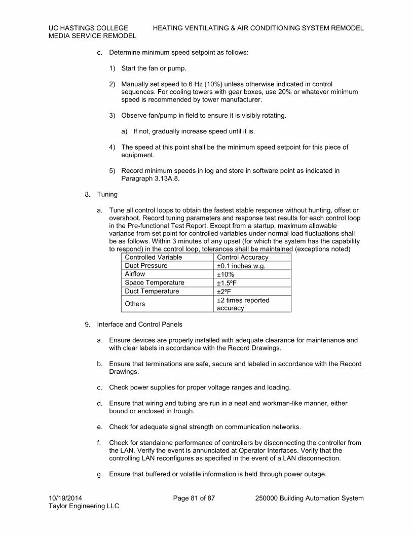
UC HASTINGS COLLEGE HEATING VENTILATING & AIR CONDITIONING SYSTEM REMODEL
MEDIA SERVICE REMODEL
10/19/2014 Page 81 of 87 250000 Building Automation System Taylor Engineering LLC
Determine minimum speed setpoint as follows:
1) Start the fan or pump.
2) Manually set speed to 6 Hz (10%) unless otherwise indicated in control sequences. For cooling towers with gear boxes, use 20% or whatever minimum speed is recommended by tower manufacturer.
3) Observe fan/pump in field to ensure it is visibly rotating.
a) If not, gradually increase speed until it is.
4) The speed at this point shall be the minimum speed setpoint for this piece of equipment.
5) Record minimum speeds in log and store in software point as indicated in Paragraph 3.13A.8.
Tuning
Tune all control loops to obtain the fastest stable response without hunting, offset or overshoot. Record tuning parameters and response test results for each control loop in the Pre-functional Test Report. Except from a startup, maximum allowable variance from set point for controlled variables under normal load fluctuations shall be as follows. Within 3 minutes of any upset (for which the system has the capability to respond) in the control loop, tolerances shall be maintained (exceptions noted)
Controlled Variable Control Accuracy
Duct Pressure ±0.1 inches w.g.
Airflow ±10%
Space Temperature ±1.5ºF
Duct Temperature ±2ºF
Others ±2 times reported accuracy
Interface and Control Panels
Ensure devices are properly installed with adequate clearance for maintenance and with clear labels in accordance with the Record Drawings.
Ensure that terminations are safe, secure and labeled in accordance with the Record Drawings.
Check power supplies for proper voltage ranges and loading.
Ensure that wiring and tubing are run in a neat and workman-like manner, either bound or enclosed in trough.
Check for adequate signal strength on communication networks.
Check for standalone performance of controllers by disconnecting the controller from the LAN. Verify the event is annunciated at Operator Interfaces. Verify that the controlling LAN reconfigures as specified in the event of a LAN disconnection.
Ensure that buffered or volatile information is held through power outage.
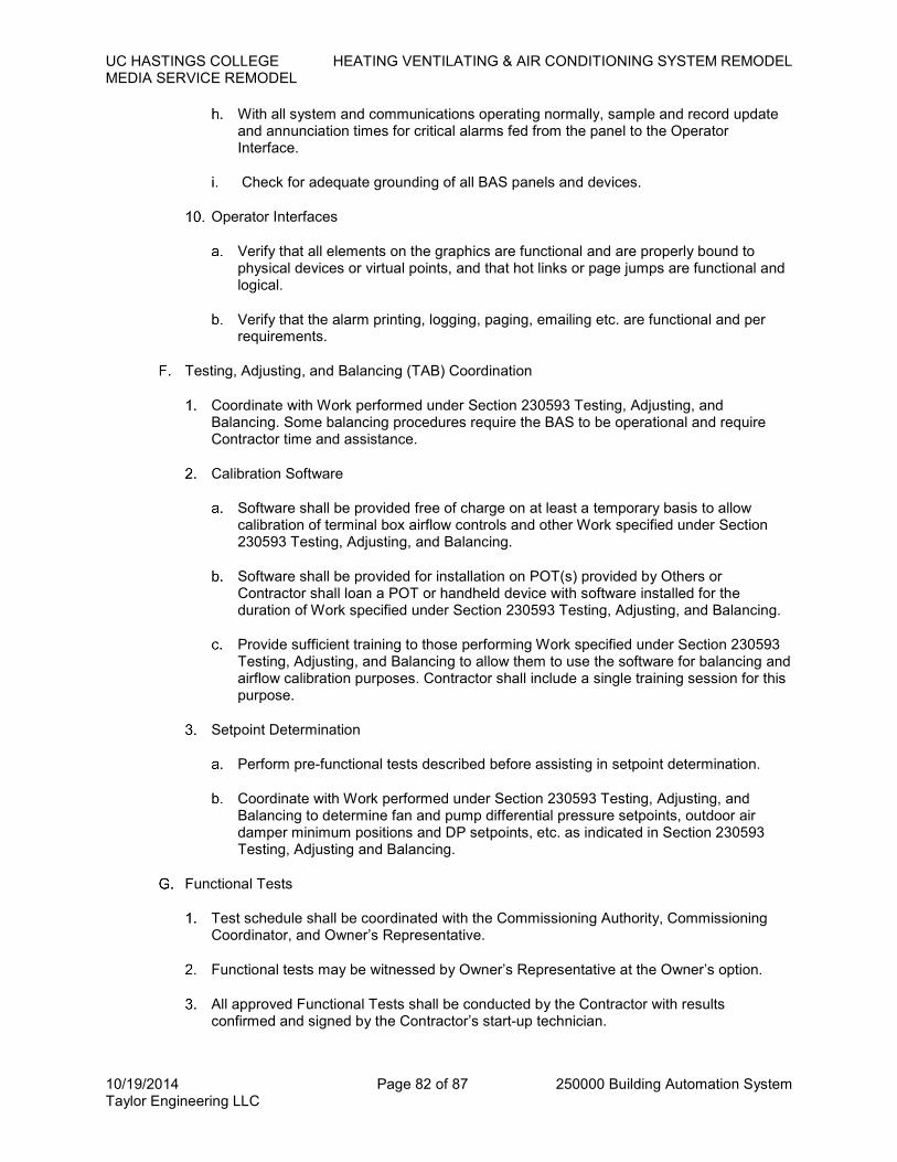
UC HASTINGS COLLEGE HEATING VENTILATING & AIR CONDITIONING SYSTEM REMODEL
MEDIA SERVICE REMODEL
10/19/2014 Page 82 of 87 250000 Building Automation System Taylor Engineering LLC
With all system and communications operating normally, sample and record update and annunciation times for critical alarms fed from the panel to the Operator Interface.
Check for adequate grounding of all BAS panels and devices.
Operator Interfaces
Verify that all elements on the graphics are functional and are properly bound to physical devices or virtual points, and that hot links or page jumps are functional and logical.
Verify that the alarm printing, logging, paging, emailing etc. are functional and per requirements.
Testing, Adjusting, and Balancing (TAB) Coordination
Coordinate with Work performed under Section 230593 Testing, Adjusting, and Balancing. Some balancing procedures require the BAS to be operational and require Contractor time and assistance.
Calibration Software
Software shall be provided free of charge on at least a temporary basis to allow calibration of terminal box airflow controls and other Work specified under Section 230593 Testing, Adjusting, and Balancing.
Software shall be provided for installation on POT(s) provided by Others or Contractor shall loan a POT or handheld device with software installed for the duration of Work specified under Section 230593 Testing, Adjusting, and Balancing.
Provide sufficient training to those performing Work specified under Section 230593 Testing, Adjusting, and Balancing to allow them to use the software for balancing and airflow calibration purposes. Contractor shall include a single training session for this purpose.
Setpoint Determination
Perform pre-functional tests described before assisting in setpoint determination.
Coordinate with Work performed under Section 230593 Testing, Adjusting, and Balancing to determine fan and pump differential pressure setpoints, outdoor air damper minimum positions and DP setpoints, etc. as indicated in Section 230593 Testing, Adjusting and Balancing.
Functional Tests
Test schedule shall be coordinated with the Commissioning Authority, Commissioning Coordinator, and Owner’s Representative.
Functional tests may be witnessed by Owner’s Representative at the Owner’s option.
All approved Functional Tests shall be conducted by the Contractor with results confirmed and signed by the Contractor’s start-up technician.

UC HASTINGS COLLEGE HEATING VENTILATING & AIR CONDITIONING SYSTEM REMODEL
MEDIA SERVICE REMODEL
10/19/2014 Page 83 of 87 250000 Building Automation System Taylor Engineering LLC
Test documentation shall be submitted to the Owner for review and approval.
Demonstration Test
Demonstration tests consist of a small representative sample of functional tests and systems randomly selected by the Commissioning Authority. Tests will be designed to occur over no longer than 1 day.
Schedule the demonstration with the Commissioning Authority and Owner’s Representative at least 1 week in advance. Demonstration shall not be scheduled until the Functional Test Report has been approved.
The Contractor shall supply all personnel and equipment for the demonstration, including, but not limited to, instruments, ladders, etc. Contractor-supplied personnel shall be those who conducted the Functional tests or who are otherwise competent with and knowledgeable of all project-specific hardware, software, and the HVAC systems.
The system will be demonstrated following procedures that are the same or similar to those used in the Pre-Functional and Functional Tests. The Commissioning Authority will supply the test forms at the site at the start of the tests.
Demonstration tests may be witnessed by Owner’s Representative at the Owner’s option.
Contractor shall conduct tests as directed by and in the presence of the Commissioning Authority and complete test forms. Completed forms shall be submitted as the Demonstration Test Report to the Commissioning Authority after tests are complete.
Demonstration Tests shall be successfully completed and approved prior to Substantial Completion.
Trend Log Tests
Trends shall be fully configured to record and store data to the server for the points and at the interval listed in Paragraph 2.9 as follows:
Commissioning: Configure trends prior to functional testing phase. Retain configuration until post-construction commissioning trend review has been completed successfully and accepted by the Owner’s representative. Trends shall be deactivated after acceptance.
Continuous: After system acceptance, configure trends for the purpose of long term future diagnostics. Configure trends to overwrite the oldest trends at the longest interval possible without filling the server hard disk beyond 80%.
Post-Construction Trend Test
Trend logging shall not commence until Demonstration Tests are successfully completed.
Hardware Points. Contractor shall configure points to trend as indicated in the Commissioning Trend column listed in Paragraph 2.9 points.
Software Points. Include the following in trends of systems and zones whose hardware points are being trended as called for above. Time interval shall be the same as associated hardware point.

UC HASTINGS COLLEGE HEATING VENTILATING & AIR CONDITIONING SYSTEM REMODEL
MEDIA SERVICE REMODEL
10/19/2014 Page 84 of 87 250000 Building Automation System Taylor Engineering LLC
1) All setpoints and limits that are automatically reset, such as supply air temperature and fan static pressure setpoints, plus the points that are driving the reset, such as zone level cooling and static pressure requests
2) All setpoints that are adjustable by occupants
3) Outputs of all control loops, other than those driving a single AO point that is already being trended
4) System mode points (e.g. Warm-up, Occupied, etc.)
5) Global overrides such as demand shed signals
6) Calculated performance monitoring points, such as chiller efficiency
Submit for review and approval by the by Commissioning Authority a table of points to be trended along with trend intervals or change-of-value a minimum of 14 days prior to trend collection period.
Trends shall be uploaded to the CSS in data format specified in Paragraph 2.9C.10.
Trend logs of all points indicated above shall be collected for a 1 week Trend Period.
At the completion of the Trend Period, data shall be reviewed by the Contractor to ensure that the system is operating properly. If so, data shall be submitted to the Owner in an electronic format agreed to by the Owner and Contractor (such as CD-ROM or via direct access to the CSS via the internet).
Data will be analyzed by the Commissioning Authority.
The system shall be accepted only if the trend review indicates proper system operation without malfunction, without alarm caused by control action or device failure, and with smooth and stable control of systems and equipment in conformance with these specifications. If any but very minor glitches are indicated in the trends, steps f to h above shall be repeated for the same Trend Period until there is a complete Trend Period of error free operation.
After successfully completing the Post-Construction Trend Tests, the Contractor shall configure all points to trend as indicated in the Continuous Trend column listed in Paragraph 2.9 points list.
Remedial Work
Repair or replace defective Work, as directed by Owner’s Representative in writing, at no additional cost to the Owner.
Restore or replace damaged Work due to tests as directed by Owner’s Representative in writing, at no additional cost to the Owner.
Restore or replace damaged Work of others, due to tests, as directed by Owner’s Representative in writing, at no additional cost to the Owner.
Remedial Work identified by site reviews, review of submittals, demonstration test, trend reviews, etc. shall be performed to the satisfaction of the Owner’s Representative, at no additional cost to the Owner.

UC HASTINGS COLLEGE HEATING VENTILATING & AIR CONDITIONING SYSTEM REMODEL
MEDIA SERVICE REMODEL
10/19/2014 Page 85 of 87 250000 Building Automation System Taylor Engineering LLC
Contractor shall compensate Owner’s Representatives and Commissioning Authority on a time and material basis at standard billing rates for any additional time required to witness additional demonstration tests or to review additional BAS trends beyond the initial tests, at no additional cost to the Owner.
3.15 TRAINING
Coordinate schedule and materials with Commissioning Authority.
Interim Training
Provide minimal training so the operating staff can respond to occupant needs and other operating requirements during start-up and commissioning phase.
Formal Training
Provide training sessions for personnel indicated in Paragraph 3.15G.
Training shall be conducted after all commissioning is complete and systems are fully operational.
Off-site Primary System Training
Training on basic BAS functions as listed in Paragraph 3.15C.3 shall be given off-site by the primary manufacturer’s training staff, either at the factory or at a permanent training facility. Training by Contractor staff is not acceptable.
The appropriate level of training shall be provided for each of the persons listed in Paragraph 3.15G.
The length of each training period will depend on the complexity of the system and the audience, described below. Minimum training shall be 24 hours per trainee, but period shall be longer if required to complete the training tasks described below.
Expenses for transportation to and from the training facility, hotel, and meals shall be provided by the Owner and excluded from the BAS bid. Cost for books, manuals and any other type of training equipment or material shall be included in the BAS bid.
On-Site Training
Include 40 hours total of on-site training to assist personnel in becoming familiar with site-specific issues, systems, control sequences, etc.
Owner shall be permitted to videotape training sessions.
Training may be in non-contiguous days at the request of the Owner.
During the warranty period, provide unlimited telephone support for all trained operators.
Operators are divided into three categories and shall receive training including but not limited to the tasks listed.
Day-to-day Operators shall be trained to
Proficiently operate the system

UC HASTINGS COLLEGE HEATING VENTILATING & AIR CONDITIONING SYSTEM REMODEL
MEDIA SERVICE REMODEL
10/19/2014 Page 86 of 87 250000 Building Automation System Taylor Engineering LLC
Understand control system architecture and configuration
Understand BAS system components
Understand system operation and control sequences
Operate the workstation and peripherals
Log on and off the system
Access graphics, point reports, and logs
Adjust and change system set points, time schedules, and holiday schedules
Recognize malfunctions of the system by observation of the printed copy and graphical visual signals
Understand and acknowledge alarms
Understand system drawings, and Operation and Maintenance manual
Understand the Project layout and location of control components
Print point and predefined reports
Advanced Operators shall be trained to do all items for Day-to-Day operators plus
Make and change graphics on the workstation
Create, delete, and modify alarms, including annunciation and routing
Create, delete, and modify point trend logs, and graph or print these both on an ad-hoc basis and at user-definable time intervals
Create, delete, and modify reports
Add, remove, and modify system’s physical points
Create, modify, and delete programming
Add control panels
Add Operator Workstations
Create, delete, and modify system displays — both graphical and otherwise
Perform BAS system field checkout procedures
Perform BAS controller unit operation and maintenance procedures
Perform workstation and peripheral operation and maintenance procedures
Perform BAS system diagnostic procedures
Configure hardware including PC boards, switches, communication, and I/O points

UC HASTINGS COLLEGE HEATING VENTILATING & AIR CONDITIONING SYSTEM REMODEL
MEDIA SERVICE REMODEL
10/19/2014 Page 87 of 87 250000 Building Automation System Taylor Engineering LLC
Maintain, calibrate, troubleshoot, diagnose, and repair hardware
Adjust, calibrate, and replace system components
Maintain software and prepare backups
System Managers/Administrators shall be trained to do all items for Day-to-Day operators plus
Maintain software and prepare backups
Create and print custom reports, including tenant billing summaries
Interface with project-specific, third-party operator software
Add new users and understand password security procedures
Training materials shall include step-by-step instructions (including illustrations, screen captures, etc.) for how to perform all task identified in Paragraph 3.15C.3 such that a new Operator, who has not attended the training in person and has minimal familiarity with this BAS system, can easily follow the instructions and successfully perform all of the identified tasks. One copy of training material shall be provided per student. An electronic copy of the materials shall be stored on the OWS.
The instructor(s) shall be factory-trained instructors experienced in presenting this material.
The type and number of personnel and location for training shall include
Day-to-day Operator: 6
Advanced Operator: 4
System Managers/Administrators: 2
END OF SECTION 250000


