UC and UD Gear pump unit Assembly instructions EN for ... UC and UD Gear pump unit Assembly...
56
UC EN UC and UD Gear pump unit Assembly instructions acc. to EC Dir. 2006/42/EC for partly completed machinery with associated operating instructions Version 05 for hydraulic or circulating-oil lubrication systems UD
Transcript of UC and UD Gear pump unit Assembly instructions EN for ... UC and UD Gear pump unit Assembly...

UC
ENUC and UD Gear pump unit Assembly instructions acc. to EC Dir. 2006/42/EC
for partly completed machinery with associated operating instructions
Version 05
for hydraulic or circulating-oil lubrication systems
UD

Page 2 EN Notes
UD and UC Gear pump unit
Masthead
These original assembly instructions with
associated operating instructions in accor-
dance with EC Machinery Directive 2006/42/EC
are an integral part of the described product
and must be kept for future use.
These original assembly instructions with
associated operating instructions have been
prepared in accordance with the established
standards and rules for technical documenta-
tion, VDI 4500 and EN 292.
© SKF Lubrication Systems Germany GmbH
This documentation is protected by copyright.
SKF Lubrication Systems Germany GmbH
reserves all rights, including those to the
photomechanical reproduction, duplication,
and distribution by means of special proce-
dures (e.g., data processing, data media, and
data networks) of this documentation in whole
or in part.
Subject to changes in contents and technical
information.
Service If you have technical questions, please contact
the following addresses:
SKF Lubrication Systems Germany GmbH
Berlin Plant
Motzener Strasse 35/37
12277 Berlin
Germany
Tel. +49 (0)30 72002-0
Fax +49 (0)30 72002-111
www.skf.com/lubrication
Hockenheim Plant
2. Industriestrasse 4
68766 Hockenheim
Germany
Tel. +49 (0)62 05 27-0
Fax +49 (0)62 05 27-101
www.skf.com/lubrication

Page 3 ENTable of contents
Table of contents
Assembly instructionsUC and UD Gear pump unit 1
Service 2
Explanation of symbols and signs 5
1. Safety instructions 7
1.1 Intended use 7
1.2 Authorized personnel 7
1.3 Electric shock hazard 8
1.4 System pressure hazard 8
1.5 Compressed air hazard 8
1.6 Hydraulic pressure hazard 8
1.7 Explosion protection information 9
2. Lubricants 10
2.1 General information 10
2.2 Selection of lubricants 10
2.3 Approved lubricants 11
2.4 Lubricants and the environment 11
2.5 Lubricant hazards 12
3. Overview 12
4. Assembly 13
4.1 Setup and attachment 13
4.1.1 Assembly of the gear pump unit 14
4.2 UC/UD Assembly drawing 15
4.2.4 Use 16
4.2.5 Design 17
4.2.6 Series 1: Qnominal up to 3 l/min 18
4.2.7 Series 2: Qnominal up to 10.8 l/min 22
4.2.8 Series 3: Qnominal up to 36 l/min 28
4.3 Electrical motor connection 35
4.4 Lubrication line connection 36
4.4.1 Lubricant illing 36
4.5 Note on the nameplate 38
4.6 Information on CE marking 38
Operating instructions 39
1. Safety instructions 40
2. Lubricants 40
3. Transport, delivery, and storage 41
3.1 Lubrication units 41
3.2 Electronic and electrical devices 41
3.3 General notes 41
4. Assembly 42
4.1 Information on assembly 42
4.2 Assembly of pump unit 42
4.3 Housing versions 42
4.4 Dismantling and disposal 42
5. Design and function 43
5.1 General information43
5.2 Design and mode of operation of
the gear pump unit 43
6. Commissioning 44
6.1 Condition on delivery 44
6.2 Commissioning 44
7. Shutdown 45
7.1 Temporary shutdown 45
7.2 Permanent shutdown 45
8. Maintenance 46
8.1 General information 47
9. Malfunction 48
9.1 Commissioning malfunctions 49
10. Accessories 50
11. Spare parts 55

Page 4 EN
EC Declaration of Incorporation acc. to Machinery Directive 2006/42/EC, Appendix II Part 1 BThe manufacturer, SKF Lubrication Systems GmbH, Hockenheim Plant, 2. Industriestrasse 4, DE - 68766 Hockenheim, hereby declares the conformity of the partly completed machinery
Designation: Gear pump unitsType: UD* / UC*Item number: 715-*Year of manufacture: See rating platewith the essential protection requirements of Machinery Directive 2006/42/EC at the time of placing on the market.
1.1.2 · 1.1.3 · 1.3.2 · 1.3.4 · 1.5.1 · 1.5.6· 1.5.8 · 1.5.9 · 1.6.1 · 1.7.1 · 1.7.3 · 1.7.4
The technical documentation described in Annex VII, part B of this Directive has been prepared. We undertake to transmit, in response to a reasoned request by the national authorities, the special documents for this partly completed machine. The Head of Technical Standards is the authorized representative for the technical documentation. See the manufacturer information for the address.
Furthermore, the following Directives and (harmonized) standards were applied in the applicable areas:2011/65/EU RoHS II 2014/30/EU Electromagnetic Compatibility | Industry
Standard Edition Standard Edition Standard Edition Standard Edition
DIN EN ISO 12100 2011 DIN EN 60947-5-1 2010 DIN EN 61000-6-2 2006 DIN EN 61000-6-4 2011
DIN EN 809 2012 DIN EN 61131-2 2008 Correction 2011 DIN EN 60947-5-1 2010
DIN EN 60204-1 2007 Correction 2009 DIN EN 61000-6-3 2011
Correction 2010 DIN EN 60034-1 2015 Correction 2012
DIN EN 50581 2013 DIN EN 61000-6-1 2007
The partially completed machinery must not be put into service until the machinery into which it is to be incorporated has been declared in conformity with the provisions of Machinery Directive 2006/42/EC and all other applicable Directives.
Hockenheim, 2016,04,25
Jürgen Kreutzkämper Manager R&D GermanySKF Lubrication Business Unit
Stefan Schürmann Manager R&D Hockenheim/Walldorf SKF Lubrication Business Unit
EC Declaration of Incorporation

Page 5 EN
Informational symbolsIndicators used with safety instructions
and their meaning
Hazard symbols
Explanation of symbols
Explanation of symbols and signs
You will ind these symbols, which warn of
speciic dangers to persons, material assets, or
the environment, next to all safety instructions
in these operating instructions.
Please heed these instructions and proceed
with special care in such cases. Please forward
all safety instructions to other users.
General hazard DIN 4844-2-W000
Electrical voltage/current
Hot surface
Indicator Use
Danger! Danger of bodily injury
Warning! Danger of damage to prop-
erty and the environment
Note! Provides additional
information
Note
Prompts an action
Used for itemizing
Points out other facts, causes, or
consequences
Provides additional information
Instructions placed directly on the machines/
grease lubrication pump units, such as:
Arrow indicators
Labels for luid connections
must be followed and kept in a fully legible
condition.
You are responsible!
Please read the assembly and operating
instructions thoroughly and follow the safety
instructions.
Danger of being drawn into machinery
DIN 4844-2-W008
DIN 4844-2-W026
BGV 8A
Slipping hazardDIN 4844-2-W028
Warning of potentially explosive atmosphereDIN 4844-2-W021

Page 6 EN Assembly instructions
Assembly instructions according to Machinery Directive 2006/42/EC, Annex VI
The assembly instructions fulfill the Machinery
Directive indicated above with regard to partly
completed machinery. Partly completed ma-
chinery, which includes the product described
herein, is only intended to be incorporated into
or assembled with other machinery or other
partly completed machinery or equipment,
thereby forming machinery to which the
above-mentioned Directive applies.

Page 7 ENAssembly instructions
The operator of the described product
must ensure that the assembly instruc-
tions are read and understood by all
persons responsible for assembly, op-
eration, maintenance, and repair of the
product. The assembly instructions
must be kept readily available.
Note that the assembly instructions
form part of the product and must ac-
company the product if sold to a new
owner.
1. Safety instructions
In addition to the assembly instructions,
statutory regulations and other general
regulations for accident prevention and
environmental protection must be ob-
served and applied.
1.2 Authorized personnel
Only qualified technical personnel may install,
operate, maintain, and repair the products de-
scribed in the assembly instructions. Qualified
technical personnel are persons who have
been trained, assigned and instructed by the
operator of the final product into which the
described product is incorporated. Such persons
are familiar with the relevant standards, rules,
accident prevention regulations, and assembly
conditions as a result of their training, experi-
ence, and instruction. They are authorized to
identify and perform necessary actions while
avoiding any risks which may arise.
The definition of qualified personnel and the
prohibition against employing non-qualified
personnel are laid down in DIN VDE 0105 and
IEC 364.
The described product is manufactured in accor-
dance with the generally accepted rules and
standards of industry practice and with occupa-
tional safety and accident prevention regulations.
Risks may, however, arise from its usage and
may result in physical harm to persons or dam-
age to other material assets. Therefore the
product may only be used in proper technical
condition and in observance of the assembly
instructions. In particular, any malfunctions
which may affect safety must be remedied
immediately.
1.1 Intended use
The UC and UD gear pump units are vertically
or horizontally arranged units that are used in
hydraulic or circulating-oil lubrication systems.
All off-the-shelf lubricants and hydraulic oils
in the viscosity range of between 20 and
1000 mm2/s are conveyed.
The use of synthetic oils requires prior approval
from SKF Lubrication Systems Germany GmbH.
Any other usage is deemed non-compliant
with the intended use.

Page 8 EN Assembly instructions
Depending on the model design, the product
may be able to be operated with compressed
air. Through the use of the appropriate com-
pressed air quality class, compressed air prep-
aration can be optimized and machine down-
time and higher maintenance costs avoided.
The compressed air to be used here must
comply with at least quality class 5 as deined
by ISO 8573-1:
Max. particle size 40 μm
Max. particle density 10mg/m³
Pressure dew point 7°C
Water content max. 7800 mg/ m³
Residual oil content max. 25 mg/ m³
1.4 System pressure hazard
Lubrication systems are pressurized
during operation. Centralized lubrication
systems must therefore be depressur-
ized before starting assembly, mainte-
nance or repair work, or any system
modifications or system repairs.
1.5 Compressed air hazard
The described product is pressurized
during operation. The product must
therefore be depressurized before
starting assembly, maintenance or repair
work, or any system modifications or
system repairs. 1.6 Hydraulic pressure hazard
The described product is pressurized
during operation. The product must
therefore be depressurized before
starting assembly, maintenance or re-
pair work, or any system modifications
or system repairs.
1.3 Electric shock hazard
Electrical connections for the described product
may only be established by qualified and
trained personnel authorized to do so by the
operator, and in observance of the local condi-
tions for connections and local regulations
(e.g., DIN, VDE). Significant bodily injury and
property damage may result from improperly
connected products.
Danger!
Work on products that have not been
de-energized may result in bodily injury.
Assembly, maintenance and repair work
may only be performed on products
that have been de-energized by quali-
fied technical personnel. The supply
voltage must be switched off before
opening any of the product's
components.

Page 9 ENAssembly instructions
1.7 Explosion protection information
Danger!
Only the pump models tested and ap-
proved by SKF Lubrication Systems
Germany GmbH in accordance with
ATEX Directive 2014/34/EU are per-
mitted to be used in areas with explo-
sion protection. The relevant class of
protection is engraved on the pump's
nameplate.
When filling lubricant into the pump,
make sure the lubricant is clean. The res-
ervoir must be filled in good time (pay at-
tention to fill level monitoring). Lubricant
must be filled only via the filler socket
G 3/8“ (FF) or G 1/2“ (FB) on the pump
flange. Lubricant may only be filled via
the "reservoir cover" if absolutely certain
that no potentially explosive atmosphere
exists.
In case of overfilling, the excessive
amount of lubricant must be removed.
Make sure there is no potentially explosive
atmosphere when doing this.
The switching circuits of the fill level
monitor must be supplied by an intrinsically
safe circuit, e.g., through the installation
of an ATEX-compliant isolating switch by
the customer. The unit must be grounded
via a ground connection. The customer
must install adequate overload protection
for the power consumption of the motor.
To avoid electrostatic discharge, lay
hydraulic connecting lines in corrosion-
resistant metal tubing, e.g., stainless steel
pipe.
When setting up the pump, make sure
the setup location is level and not subject
to vibrations or jolts.
During maintenance work, use only tools
intended for use in potentially explosive
spaces or else make certain that there is
no potentially explosive atmosphere
present.
The service life of the oil lubrication pump
is limited. It must therefore undergo a
function and leak test at regular intervals.
Perform appropriate repairs in the event
of malfunctions, leaks, or rust. Replace
the pump if necessary.
The user must make sure through the
choice of the lubricant to be delivered that
no chemical reactions capable of serving
as ignition sources will occur in conjunction
with the explosive atmospheres expected.
The lubricant’s ignition temperature has to
be at least 50 kelvin above the pump’s
maximum surface temperature
(temperature class).
Page 10 EN Assembly instructions
2. Lubricants
2.1 General information
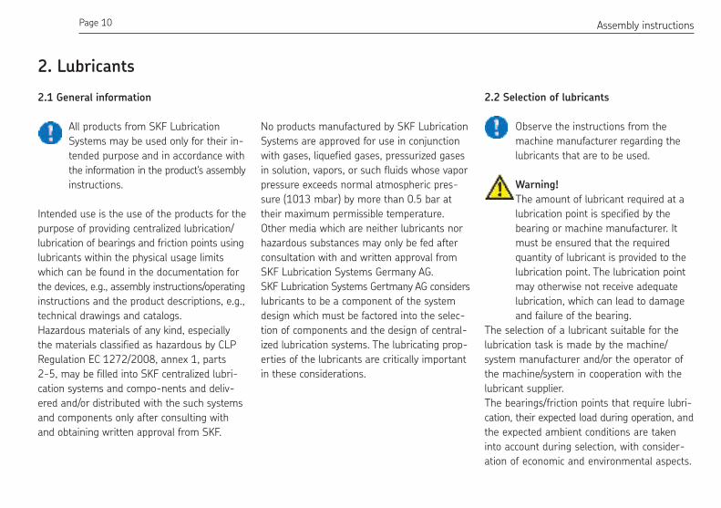
All products from SKF Lubrication
Systems may be used only for their in-
tended purpose and in accordance with
the information in the product's assembly
instructions.
Intended use is the use of the products for the
purpose of providing centralized lubrication/
lubrication of bearings and friction points using
lubricants within the physical usage limits
which can be found in the documentation for
the devices, e.g., assembly instructions/operating
instructions and the product descriptions, e.g.,
technical drawings and catalogs.
Hazardous materials of any kind, especially
the materials classified as hazardous by CLP
Regulation EC 1272/2008, annex 1, parts
2-5, may be filled into SKF centralized lubri-
cation systems and compo-nents and deliv-
ered and/or distributed with the such systems
and components only after consulting with
and obtaining written approval from SKF.
No products manufactured by SKF Lubrication
Systems are approved for use in conjunction
with gases, liquefied gases, pressurized gases
in solution, vapors, or such fluids whose vapor
pressure exceeds normal atmospheric pres-
sure (1013 mbar) by more than 0.5 bar at
their maximum permissible temperature.
Other media which are neither lubricants nor
hazardous substances may only be fed after
consultation with and written approval from
SKF Lubrication Systems Germany AG.
SKF Lubrication Systems Gertmany AG considers
lubricants to be a component of the system
design which must be factored into the selec-
tion of components and the design of central-
ized lubrication systems. The lubricating prop-
erties of the lubricants are critically important
in these considerations.
2.2 Selection of lubricants
Observe the instructions from the
machine manufacturer regarding the
lubricants that are to be used.
Warning!
The amount of lubricant required at a
lubrication point is specified by the
bearing or machine manufacturer. It
must be ensured that the required
quantity of lubricant is provided to the
lubrication point. The lubrication point
may otherwise not receive adequate
lubrication, which can lead to damage
and failure of the bearing.
The selection of a lubricant suitable for the
lubrication task is made by the machine/
system manufacturer and/or the operator of
the machine/system in cooperation with the
lubricant supplier.
The bearings/friction points that require lubri-
cation, their expected load during operation, and
the expected ambient conditions are taken
into account during selection, with consider-
ation of economic and environmental aspects.

Page 11 ENAssembly instructions
2.4 Lubricants and the environment
Lubricants can contaminate soil and
bodies of water. Lubricants must be
properly used and disposed of. Observe
the local regulations and laws regarding
the disposal of lubricants.
It is important to note that lubricants are envi-
ronmentally hazardous, flammable substances
that require special precautionary measures
during transport, storage, and processing.
Consult the safety data sheet from the lubricant
manufacturer.
Where necessary, SKF Lubrication
Systems supports customers in the
selection of suitable components for
feeding the selected lubricant and in
the planning and design of a centralized
lubrication system.
Please contact SKF Lubrication Systems if you
have further questions regarding lubricants.
Lubricants can be tested in the company's lab-
oratory for their suitability for pumping in cen-
tralized lubrication systems (e.g., "bleeding").
You can request an overview of the lubricant
tests offered by SKF Lubrication Systems from
the company's service department.
2.3 Approved lubricants
Only lubricants approved for the product
may be used. Unsuitable lubricants can
lead to failure of the product and damage
to property.
Different lubricants must not be mixed,
as mixing may result in damage and
necessitate costly and complicated
cleaning of the product/lubrication sys-
tem. It is recommended that an indication
of the lubricant in use be attached to
the lubricant reservoir in order to prevent
accidental mixing of lubricants.
The product described here can be operated
using lubricants that meet the specifications in
the technical data. Depending on the product
design, these lubricants may be oils, fluid
greases, or greases.
Oils and base oils may be mineral, synthetic,
and/or rapidly biodegradable. Consistency
agents and additives may be added depending
on the operating conditions.
Note that in rare cases, there may be lubricants
whose properties are within permissible limit
values but whose other characteristics render
them unsuitable for use in centralized lubrication
systems. For example, synthetic lubricants
may be incompatible with elastomers.

Page 12 EN Assembly instructions
3. Overview
Components of the unit
Item description
1 Electric motor with terminal box
2 Pump skirt with coupling
3 Gear pump
For information regarding transport, storage,
processing, and environmental hazards of the
lubricant that will be used.
The safety data sheet for a lubricant can be
requested from the lubricant manufacturer.
2.5 Lubricant hazards
Centralized lubrication systems must
always be free of leaks. Leaking lubricant
is hazardous due to the risk of slipping
and injury. Beware of any lubricant
leaking out during assembly, operation,
maintenance, and repair of centralized
lubrication systems. Leaks must be
sealed without delay.
Lubricant leaking from centralized lubrication
systems is a serious hazard. Leaking lubricant
can create risks that may result in physical
harm to persons or damage to other material
assets.
Follow the safety instructions on the lu-
bricant's safety data sheet.
Lubricants are hazardous substances. The
safety instructions on the lubricant's safety
data sheet must be strictly followed. The safety
data sheet for a lubricant can be requested
from the lubricant manufacturer.
Fig. 1 Components of the UD unit
1
2
3

Page 13 ENAssembly instructions
Components of the unit
Item description
1 Electric motor with terminal box
2 Gear pump with coupling
1
2
4. Assembly
4.1 Setup and attachment
The product should be protected from humidity
and vibration, and should be mounted so that
it is easily accessible, allowing all further in-
stallation work to be done without difficulty.
Make sure there is adequate air circulation to
prevent the product from overheating. For the
maximum permissible ambient temperature,
see "Technical data."
There are no restrictions with regard to the
mounting position of all the units.
During assembly and especially when drilling,
always pay attention to the following:
Existing supply lines must not be dam-
aged by assembly work.
Other units must not be damaged by as-
sembly work.
The product must not be installed within
range of moving parts.
The product must be installed at an ad-
equate distance from sources of heat.
Maintain safety clearances and comply
with local regulations for assembly and
accident prevention.
Fig. 2 Components of the UC unit

Page 14 EN Assembly instructions
The gear pump unit must be installed on a
level surface. The base plate must not be under
stress. Suficient space must be provided dur-
ing installation for later servicing and mainte-
nance work.
4.1.1 Assembly of the gear pump unit
Warning!
When drilling the assembly holes, you
must be careful of any supply lines or
other units, as well as of other hazards
such as moving components.
Maintain safety clearances and comply
with local regulations for assembly and
accident prevention.
There are no restrictions with regard to the
mounting position of all the units.
When UC units are to be mounted lower
than the maximum liquid level, additional
sealing of the flange face is required
(refer to version key).
Warning!
The torque of the fastening screws de-
pends on the customer’s installation.
Make sure that torque is adequate
when installing the base plate!

Page 15 ENAssembly instructions
UC and UD Gear pump unit
4.2 UC/UD Assembly drawing
UC UD
UC

Page 16 EN Assembly instructions
The gear pump units are manufactured in
3 assemblies:
Series 1 is approved for very high viscosities
up to 1.000 mm2/s. They are characterized by
their simple and small design, and are accord-
ingly inexpensive. They are particularly suited
for small hydraulic and lubrication systems that
require volumetric flows between
0.06 l/min and 3 l/min for operating pressures
between 25 bar and 60 bar.
Series 2 and series 3 meet high requirements
in terms of volumetric flow, operating pressure
and efficiency. While series 2 has been de-
signed for volumetric flows of between 1 l/min
and 10.8 l/min, series 3 covers the range be-
tween 3.8 l/min and 36 l/min. Within the series,
the permissible operating pressure is greater
the smaller the nominal volumetric flow.
4.2.4 Use
Due to the overlapping volumetric flow ranges,
it is possible, for instance, to convey 9 l/min
using a series 2 pump in the low-pressure
range, whereas a corresponding series 3
Series 1-3 (not to scale) Fig. 1
Q [l/min]
4
0,01 0,02 0,050,03 0,1
2
1
3
0,20,4
0,3 0,5 1 2
5
10
30
20
4050
100
200
300
43 5 10 3020 40 50
p [b
ar]
Series 1
Series 2 Series 3
pump can achieve this volumetric flow in the
high-pressure range for the same efficiency.
The respective ranges of the series are shown
in a simple form in Fig. 1.

Page 17 ENAssembly instructions
The gear pump units consist of motor, coupling,
flange and gear pump.
Series 1:
Rated motor output 0.18 kW.
Delivery volume between 0.06 l/min at 60 bar
and 3 l/min at 25 bar.
Flange size:
116 x 116 mm (vertical position) and
80 x 120 mm (horizontal position).
Note!
There is the series 1 still in more customised
implementation with an engine rated power of
0.25 kW. Calculation current is according to
him to lay out type plate.
Series 2:
Rated motor output 0.18; 0.37; 0.55 or
0.75 kW.
By combination with gear pump units of
different sizes (1.2 cm3/revolution to
8 cm3/revolution), a wide spectrum with regard
to the selection criteria volumetric flow and
operating pressure is achieved.
Delivery volume from 1 l/min at 200 bar up to
10.8 l/min at 30 bar.
Flange size:
150 x 150 mm (vertical position) and
120 x 150 mm (horizontal position).
Series 3:
Rated motor output from 0.75 kW to 4 kW.
The gear pump unit has a displacement
between 4.5 cm3/revolution and
26 cm3/revolution.
Delivery volume 3.8 l/min at 200 bar
up to 36 l/min at 45 bar.
Flange size:
205 x 205 mm (vertical position) and
180 x 220 mm (horizontal position).
4.2.5 Design

Page 18 EN Assembly instructions
UD gear pump unit, Series 1UC gear pump unit, Series 1
Ø140
Ø70
Y
232
11
16
A
Ø6.4
13
Pg16 19
0
116
100±0.2
8
1
1315
13
Ø19
17
100±
0.2
108
60±0.2
11.5
817
Ø70
75
13
120
100±0.2
6
Ø6.4
108
1315
80
184
Pg16
232A
Ø14
0Y
M10x1 connection for pressure regulating valve
Suction port G 3/8"
Pressure port G 1/4"
M10x1 connection for pressure regulating valve
Pressure port G 1/4" Suction port G 3/8"
View YView Y
4.2.6 Series 1: Qnominal
up to 3 l/min
Dimension A
- see Page 20
Dimension A
- see Page 20
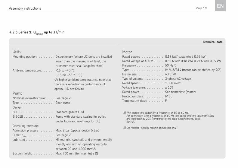
Page 19 ENAssembly instructions
Units Mounting position: . . . . . . . . . Discretionary (where UC units are installed
lower than the maximum oil level, the
customer must seal flange/machine)
Ambient temperature: . . . . . . . -15 to +40 °C
(-15 bis +55 °C 2) )
(At higher ambient temperatures, note that
there is a reduction in performance of
approx. 1% per Kelvin)
Pump Nominal volumetric flow: . . . . See page 20
Type: . . . . . . . . . . . . . . . . . . . . Gear pump
Design:
B 1. . . . . . . . . . . . . . . . . . . . . . Standard gasket FPM
B 3018 . . . . . . . . . . . . . . . . . . Pump with standard sealing for outlet
under lubricant level (only for UC)
Operating pressure:
Admission pressure . . . . . . . . Max. 2 bar (special design 5 bar)
Outlet pmax
. . . . . . . . . . . . . . . . See page 20
Lubricant . . . . . . . . . . . . . . . . . Mineral oils, synthetic and environmentally
friendly oils with an operating viscosity
between 20 and 1.000 mm2/s
Suction height . . . . . . . . . . . . . Max. 700 mm (for max. tube Ø)
Technical data
MotorRated power: . . . . . . . . . . . . . 0.18 kW/ customized 0.25 kW
Rated voltage at 400 V . . . . . . 0.65 A with 0.18 kW/ 0.91 A with 0.25 kW
Frequency . . . . . . . . . . . . . . . . 50 Hz 1)
Type: . . . . . . . . . . . . . . . . . . . . IM V18/B14 (motor can be shifted by 90°)
Frame size: . . . . . . . . . . . . . . . 63 C 90
Type of voltage: . . . . . . . . . . . 3-phase AC voltage
Rated speed . . . . . . . . . . . . . . 1.500 min-1
Voltage tolerance: . . . . . . . . . . ± 10%
Rated power . . . . . . . . . . . . . . See nameplate (motor)
Protection class: . . . . . . . . . . . IP 55
Temperature class: . . . . . . . . . F
1) The motors are suited for a frequency of 50 or 60 Hz. For connection with a frequency of 60 Hz, the speed and the volumetric flow are increased by 20% (compared to the table specifications, basis 50 Hz).
2) On request -special marine application only
4.2.6 Series 1: Qnominal
up to 3 l/min

Page 20 EN Assembly instructions
Technical data
Nominal volumetric flow
p=0 [l/min]
Operating pressure
pmax
[bar]
Dim. A see DWG page 18
[mm]
UC weight
[kg]
UD weight
[kg]
0.06
60
45 7.9 6.50.12
0.18
0.25
0.35 39 7.9 6.5
0.50 40 8 6.6
0.7545 8.2 6.8
1.00
1.50 50
47
8.3 6.9
2.00 35 8.4 7.0
2.5 30 8.5 7.1
3.00 25 51 8.6 7.2
4.2.6 Series 1: Qnominal
up to 3 l/min

Page 21 ENAssembly instructions
Technical data
Example: UC 0.06 / 60 AF 07 B1
1) This data refers to three-phase motors from VEM. There may be differences with motors from other manufacturers.
Other specifications available on request.
Nominal volumetric flow
p=0 [l/min]
Continuous volumetric flow
p=pmax
[l/min]
Operating pressure
[bar]
0.06 0.048
600.12 0.096
0.18 0.144
0.25 0.20
0.35 0.28
0.50 0.40
0.75 0.60
1.00 0.80
1.50 1.35 50
2.00 1.80 35
2.50 1.90 30
3.00 2.40 25
Gear pump unit
Vertical UC
Horizontal UD
Motor output data 1)
Rated speed 1)
[rpm]
Rated voltage
[V]
Order code
1500
230 / 400 AF
290 / 500 AK
400 / 690 AO
Protection class Order codes
IP55 07
Design key
Standard gasket FPM B1
Techn. data, see page 19 B 3018
with 0.25 kW B 4039
4.2.6 Series 1: Qnominal
up to 3 l/min

Page 22 EN Assembly instructions
UD gear pump unit, Series 2UC gear pump unit, Series 2
M30x1.5 connection for pressure regulating valve
Suction port G 1/2" can be turned by 90°
Pressure port G 3/8" G 1/2" 38
130
M8x16
�
234
4522
����
150
����
�
�� ����
3815
0B
279
88
130
112
38
Specification (*) = 0.18 kW motor
View Y
55
105
3920
11
B120100
5 15
124 (108*)
A
Y
80
Ø162
(130
*)
234 (190*)
4848
125150
for M8x30 nut
Pressure port G 1/2"
Suction port G 1/2"
View Y
Pressure port and suction port can be turned by 90°.
Specification (*) = 0.18 kW motor
4.2.7 Series 2: Qnominal
up to 10.8 l/min
Dimension A
- see Page 24
Dimension A
- see Page 25

Page 23 ENAssembly instructions
Units Mounting position: . . . . . . . Discretionary (where UC units are installed
lower than the maximum oil level, the cus-
tomer must seal flange/machine)
Ambient temperature: . . . . . -15 to +40 °C
. . . . . . . . . . . . . . . . . . . . . . .(-15 bis +55 °C 3) )
(At higher ambient temperatures, note that
there is a reduction in performance of approx.
1% per Kelvin)
Pump Nominal volumetric flow: . . See page 24
Type: . . . . . . . . . . . . . . . . . . Gear pump
Design:
B 1. . . . . . . . . . . . . . . . . . . . Standard gasket FPM
B 3018 . . . . . . . . . . . . . . . . Pump with standard sealing for outlet under
lubricant level (only for UC)
Operating pressure:
Admission pressure . . . . . . max. 2 bar
Outlet pmax
. . . . . . . . . . . . . . See page 24
Lubricant . . . . . . . . . . . . . . . Mineral oils, synthetic and environmen-
tally friendly oils with an operating viscosity
between 20 and 1.000 mm2/s
Suction height . . . . . . . . . . . Max. 1200 mm (for max. tube Ø)
Technical data
Rated motor power 1) 0.18 [KW]
0.37 [KW]
0.55 [KW]
0.75 [KW]
Rated voltage
at 400 V
0.65 [A]
1.22 [A]
1.73 [A]
2.1 [A]
Size 63C90 80C120
Type IM V18 or IMB14
Motor can be shifted by 90°
Type of voltage 3-phase AC voltage
Frequency 2) 50 Hz
Voltage and rated power See table page 26
Protection class IP 55
Temperature class F
1) The motors are suited for a frequency of 50 or 60 Hz. 2) For connection with a frequency of 60 Hz, the speed and the volumetric flow
are increased by 20% (compared to the table specifications, basis 50 Hz).3) On request -special marine application only
4.2.7 Series 2: Qnominal
up to 10.8 l/min

Page 24 EN Assembly instructions
UC, Series 2 Technical data
Nominal volumetric flow 1) p=0 [l/min]
Operating pressure p
max [bar]Flange Dim. A 1)
[mm]Dim. B 1)
[mm]Weight
[kg]
1.0140
80C120 116.5 90.510.0
200 11.2
1.645 63C120 7.5
180 80C120 13.5
2.3
30 63C120118.5 91.5
7.5
10080C120
11.5
130 13.5
3.5
20 63C120122 93
7.5
6580C120
11.5
90 13.5
4.8
15 63C120126 95.5
7.5
4580C120
11.5
65 13.5
7
10 63C120132.5 98.5
7.6
3080C120
11.6
45 13.6
9
8 63C120137.5 101
7.6
2580C120
11.6
35 13.6
10.8
7 63C120143 104
7.7
2080C120
11.7
30 13.7
4.2.7 Series 2: Qnominal
up to 10.8 l/min1) see DWG page 22

Page 25 ENAssembly instructions
UD, Series 2 Technical data
Nominal volumetric flow p=0 [l/min]
Operating pressure p
max [bar]Flange Dim. A
[mm]Dim. B [mm]
Weight [kg]
1.0140
80C120 82.5 33.510.0
200 11.2
1.645 63C120 7.5
180 80C120 13.5
2.3
30 63C120
84.5 34.5
7.5
10080C120
11.5
130 13.5
3.5
20 63C120
88 36
7.5
6580C120
11.5
90 13.5
4.8
15 63C120
92 38.5
7.5
4580C120
11.5
65 13.5
7
10 63C120
98.5 41.5
7.6
3080C120
11.6
45 13.6
9
8 63C120
103.5 44
7.6
2580C120
11.6
35 13.6
10.8
7 63C120
109 47
7.7
2080C120
11.7
30 13.7
4.2.7 Series 2: Qnominal
up to 10.8 l/min

Page 26 EN Assembly instructions
Technical data
Example: UC 1 / 140 A AG 07 B1
Nominal volumetric flow 2) p=0 [l/min]
Operating pressure [bar]
Rated speed [rpm]
Rated power [kW]
Rated current at 400 V [A]
1.0 140 200
1000 0.37 0.55
1.221.73
1.6 45 180
1500 0.180.75
0.652.10
2.3 30 100 130
1500 0.180.550.75
0.651.62.10
Gear pump unit
Vertical UC
Horizontal UD
Series 2 A
Protection class Order codes
IP55 07
Design key
Standard gasket FPM B1
Techn. data, see page 23
B 3018
Motor output data 1)
Rated speed 1)
[rpm]
Rated voltage
[V]
Order code
1000 230 / 400290 / 500 400 / 690
AGALAP
1500 230 / 400290 / 500 400 / 690
AFAKAO
4.2.7 Series 2: Qnominal
up to 10.8 l/min
Continued on page 27 ->

Page 27 ENAssembly instructions
Technical data
Nominal volumetric flow 2) p=0 [l/min]
Operating pressure [bar]
Rated speed [rpm]
Rated power [kW]
Rated current at 400 V [A]
3.5 20 65 90
15000.180.550.75
0.651.62.10
4.8 15 45 65
1500 0.180.550.75
0.651.62.10
7 10 30 45
1500 0.180.550.75
0.651.62.10
9 8 25 35
1500 0.180.550.75
0.651.62.10
10.8 7 20 30
1500 0.180.550.75
0.651.62.10
1) This data refers to three-phase motors from VEM. There may be differences with motors from other manufacturers.2) A by 30% decreased volumetric flow must be expected for a service viscosity < 100 mm2/s and max. operating pressure.
4.2.7 Series 2: Qnominal
up to 10.8 l/min
Continued from page 26

Page 28 EN Assembly instructions
UD gear pump unit, Series 3UC gear pump unit, Series 3
4.2.8 Series 3: Qnominal
up to 36 l/min
158
68
13
5
190
220
27-G 1
/2˝34-
G 3/4˝
B
92,1-G 1
/2˝85,1
-G 3/4˝ 2
0 20
68
180
150
15
15
,9
A 115
Ø2
03
(2
28
*)
Pg21
312 (335*)50
170
54170
160 154
312
(335
*)28A
51
Pg16
Ø194
205
Ø203 (228*)
20550
B36
3 (3
86*)
Y
M30x1.5 connection for pressure regulating valve
Suction port G 1/2" up to 11.5 l/min G 3/4" > 11.5 l/min
Pressure port G 3/8" > 20.5 l/min
For M12x35 nut
Y
(*) For 4 kW or 2.2 kW motors (*) For 4 kW or 2.2 kW motors
for M 8X20 nut
Pressure port G 1/2" up to 20.5 l/min
Suction port G 1/2" up to 11.5 l/min G 3/4" > 11.5 l/min
Pressure port G 1/2" up to 20.5 l/min G 3/8" > 20.5 l/min
Pressure port and suction port can be turned by 90°.
View Y
View Y
4.2.8 Series 3: Qnominal
up to 36 l/min
Dimension A
- see Page 30/31
Dimension A
- see Page 30/31

Page 29 ENAssembly instructions
Units Mounting position: . . . . . . . . . Discretionary (where UC units are installed
lower than the maximum oil level, the
customer must seal flange/machine)
Ambient temperature: . . . . . . . -15 to +40 °C
(-15 bis +55 °C 2) )
(At higher ambient temperatures, note that
there is a reduction in performance of
approx. 1% per Kelvin)
Pump Nominal volumetric flow: Page 30
Type: . . . . . . . . . . . . . . . . . . . . Gear pump
Design:
B 1. . . . . . . . . . . . . . . . . . . . . . Standard gasket FPM
B 3018 . . . . . . . . . . . . . . . . . . Pump with standard sealing for outlet
under lubricant level (only for UC)
Operating pressure:
Admission pressure . . . . . . . . Max. 2 bar (overpressure)
Outlet pmax
. . . . . . . . . . . . . . . . See page 30
Lubricant . . . . . . . . . . . . . . . . . Mineral oils, synthetic and environmentally
friendly oils with an operating viscosity
between 20 and 1.000 mm2/s
Suction height . . . . . . . . . . . . . Max. 1.200 mm (for max. tube Ø)
Technical data, Series 3
MotorRated power. . . . . . . . . . . . . . . Page 32
Type: . . . . . . . . . . . . . . . . . . . . V18/B14 (motor can be shifted by 90°)
Type of voltage: . . . . . . . . . . . 3-phase AC voltage
Rated speed . . . . . . . . . . . . . . 1.500 min-1
Voltage tolerance: . . . . . . . . . . ± 10%
Rated current . . . . . . . . . . . . . See rating plate (motor)
Frequency . . . . . . . . . . . . . . . . 50 Hz 1)
Protection class: . . . . . . . . . . . IP 55
Temperature class: . . . . . . . . . F
1) The motors are suited for a frequency of 50 or 60 Hz. For connection with a frequency of 60 Hz, the speed and the volumetric flow are increased by 20% (compared to the table specifications, basis 50 Hz).
2) On request -special marine application only
4.2.8 Series 3: Qnominal
up to 36 l/min

Page 30 EN Assembly instructions
4.2.8 Series 3: Qnominal
up to 36 l/min
UC/UD technical data, Series 3
Nominal volumetric flow
p=0 [l/min]
Operating pressure p
max [bar]
Flange UC UD
Dim. A [mm]
Dim. B [mm]
Weight [kg]
Dim. A [mm]
Dim. B [mm]
Weight [kg]
3.8
8090C200
153 123.8
15.5
88 20.3
14.5
120 16.5 15.5
160 100C200 18.5 17.5
200 112C200 20 19
6.0
7590C200
16.5 15.5
100 18.5 17.5
150100C200
20 19
200 26 25
8.5
5090C200
16.5 15.5
70 18.5 17.5
100100C200
20 19
140 26 25
180 112C200 31 30
11.5
4090C200
17 16
50 19 18
80 110C200 20.5 19.5
100 100C200 26.5 25.5
140 112C200 31.5 30.5
Continued on page 31 ->

Page 31 ENAssembly instructions
UC/UD technical data, Series 3
Nominal volumetric flow
p=0 [l/min]
Operating pressure p
max [bar]
Flange UC UD
Dim. A [mm]
Dim. B [mm]
Weight [kg]
Dim. A [mm]
Dim. B [mm]
Weight [kg]
13.7
2090C200
169 149.316
104 28.315
35 17 1640 110C200 19 16.870 112C200 20.5 19.5
15.0
3090C200
17 1640 19 1860
100C20020.5 19.5
80 26.5 25.5110 112C200 31.5 30.5
20.5
2090C200
17 1630 19 1840
100C20020.5 19.5
60 26.5 25.580 112C200 31.5 30.5
26
1790C200
179 155.317.5
114 34.316.5
22 19.5 18.535
100C20021 20
45 27 2660 112C200 32 31
30
1590C200
183 157.3
17.5118 36.55
16.520 19.5 18.530
100C20021 20
40 27 2650 112C200 32 31
36
1290C200
17.7 16.717 19.7 18.725
100C20021.2 20.2
35 27.2 26.245 112C200 32.2 31.2
Continued from page 30

Page 32 EN Assembly instructions
Example: UC 3.8 / 80 B AG 07 B1
Gear pump unit
Vertical UC
Horizontal UD
Protection class Order codes
IP55 07
Series 3 B
Motor output data 2)
Rated speed 1)
[rpm]
Rated voltage
[V]
Order code
1000230 / 400290 / 500 400 / 690
AGALAP
1500230 / 400290 / 500 400 / 690
AFAKAO
Design key
Standard gasket FPM B1
Techn. data, see page 29
B 3018
4.2.8 Series 3: Qnominal
up to 36 l/min
Nominal volumetric flow 2) p=0 [l/min]
Operating pressure [bar]
Rated speed 1) [rpm]
Rated power1) [kW]
Rated current at 400 V [A]
3.8 80120140 200
10000.751.11.52.2
2.433.153.405.35Continued on page 33 ->Note 1 - See page 34

Page 33 ENAssembly instructions
Nominal volumetric flow 2) p=0 [l/min]
Operating pressure [bar]
Rated speed 1) [rpm]
Rated power1) [kW]
Rated current at 400 V [A]
6.0
75 100 150 200
1500
1.11.52.2
3
2.623.405.156.70
8.5
5070
100140 180
1500
1.11.52.2
34
2.623.405.156.708.80
11.5
40 50 80
100140
1500
1.11.52.2
34
2.623.405.156.708.80
13.7
20 354070
1000
0.751.11.52.2
2.433.153.405.35
15.0
30406080
110
1500
1.11.52.2
34
2.623.405.156.708.80
Continued on page 34 ->
Continued from page 32
Note 1 - See page 34

Page 34 EN Assembly instructions
Nominal volumetric flow 2) p=0 [l/min]
Operating pressure [bar]
Rated speed 1) [rpm]
Rated power1) [kW]
Rated current at 400 V [A]
20.5
2030406080
1500
1.11.52.2
34
2.623.405.156.708.80
26.0
1722354560
1500
1.11.52.2
34
2.623.405.156.708.80
30
1520304050
1500
1.11.52.2
34
2.623.405.156.708.80
36
1217253545
1500
1.11.52.2
34
2.623.405.156.708.80
1) This data refers to three-phase motors from VEM. There may be differences with motors from other manufacturers.2) Other specifications available on request.
Continued from page 33

Page 35 ENAssembly instructions
4.3 Electrical motor connection
Electric shock hazard
Electrical connections for the product
may only be established by qualified
and trained personnel authorized to do
so by the operator.
The local conditions for connections and local
regulations (e.g., DIN, VDE) must be observed.
Significant bodily injury and property damage
may result from improperly connected
products.
Warning!
Connect lines in accordance with the
technical specifications and the local
conditions for connections and local
regulations (e.g., DIN, VDE).
Consult the motor's rating plate for the electrical
characteristics of the motor, such as rated power,
rated voltage, and rated current. Observe the
guidelines in EN 60034-1 (VDE 0530-1) for
operation at the limits of the ranges A (combi-
nation of ±5% voltage deviation and ±2%
frequency deviation) and B (combination of
±10% voltage deviation and +3/-5% frequency
deviation). This applies especially with regard
to heating and deviations in operating param-
eters from the ratings on the motor's name-
plate. The limits must never be exceeded.
Warning!
The available mains voltage (supply
voltage) must be in accordance with the
specifications on the rating plate of the
motor or of the electrical components.
Check the fuse protection of the electrical circuit.
Use only fuses with the prescribed amperage,
else bodily injury and property damage may
result.
Be sure to connect the motor so as to guarantee
a continuously safe electrical connection (no
protruding wire ends); use the assigned cable
end fittings (e.g. cable lugs, wire end ferrules).
Select connecting cables conforming to DIN
VDE 0100 taking into account the rated current
and the conditions of the specific system (e.g.
ambient temperature, type of routing etc. in
accordance with DIN VDE 0298 or IEC / EN
60204-1). Details regarding electrical connec-
tion of the motor to the power supply, especially
terminal and connector pin assignment, can
be taken from the customer's drawing for the
reservoir unit.
Warning!
When establishing electrical connection
of the pump motor, be mindful of the
correct direction of rotation of the
motor.
If the direction of rotation of a motor is
marked on the product by a rotation arrow,
the motor's direction of rotation must match
the arrow.
Connect the pump unit motor according to the specifications on the motor rating plate and the motor characteristics.

Page 36 EN Assembly instructions
4.4 Lubrication line connection
The lubrication line must be connected to the
lubrication unit in such a way that no forces
can be transferred to the assembled lubrication
unit (stress-free connection).
Danger!
The fittings used to connect the lubri-
cation line should be rated for the max-
imum operating pressure of the lubri-
cation unit. If they are not, the
lubrication line system needs to be pro-
tected from excessive pressure by
means of a pressure-limiting valve.
For operating pressures up to 45 bar as can
occur especially in single-line piston distributor
systems, SKF fittings for solderless pipe unions
can be used (double tapered sleeves or tapered
sleeves). For higher operating pressures up to
250 bar as can occur especially in progressive
centralized lubrication systems, SKF cutting-
sleeve screw unions conforming to DIN 2353
can be used.
If using fittings from other manufacturers, pay
careful attention to the assembly instructions
and technical specifications provided by the
manufacturer.
4.4.1 Lubricant filling
When arranging the main and secondary
lubricant lines, observe the following instructions
in order to ensure that the entire lubrication
system functions smoothly.
The main lubricant line must be dimensioned
in accordance with the maximum operating
pressure occurring in the lubrication unit used
and the displacement volume of that lubrication
unit. If possible, the main lubricant line should
rise upward from the lubrication unit and be
ventable at the highest point on the lubrication
line system. Lubricant distributors at the end
of the main lubricant line must be installed
such that the outlets of the lubricant distributors
point upwards. If the system configuration
requires that the lubricant distributors be
arranged below the main lubricant line, they
should not be placed at the end of the main
lubricant line.
The pipes, tubes, shutoff valves and directional
control valves, fittings, etc. that will be used
must be designed for the maximum operating
pressure of the lubrication unit, the permissible
temperatures and the lubricants that will be
delivered. In addition, the lubrication line system
needs to be protected from excessive pressure
by means of a pressure-limiting valve.
All components of the lubrication line system
such as pipes, tubes, shutoff valves, directional
control valves, fittings, etc. must be carefully
cleaned before assembly. No seals should
point inward in the lubrication line system, as
this could hinder lubricant flow and introduce
contaminants into the lubrication line system.

Page 37 ENAssembly instructions
Warning!
Centralized lubrication systems must
always be free of leaks. Leaking lubricant
is hazardous due to the risk of slipping
and injury. Be mindful of any lubricant
leaking out during assembly, operation,
maintenance, and repair of centralized
lubrication systems. Leaks must be
sealed without delay.
Lubricant leaking from centralized lubrication
systems is a serious hazard. Leaking lubricant
can create risks that may result in physical
harm to persons or damage to other material
assets.
Warning!
Lubrication lines must always be free of
leaks. Lubrication lines should always
be arranged so that air pockets cannot
form anywhere. Avoid changes in the
cross-section of the lubrication line
from small to large cross-sections in
the direction of flow of the lubricant.
When the cross-section does change,
the transition should be gentle.
The flow of lubricant in the lubrication lines
should not be hindered by the installation of
sharp bends, angle valves, or flap valves. Any
unavoidable changes in the cross-section of
the lubrication line should be realized as gentle
transitions. Sudden changes of direction
should be avoided if possible.
Warning!
Follow the safety instructions on the
lubricant's safety data sheet.
Lubricants are hazardous substances. The
safety instructions on the lubricant's safety
data sheet must be strictly followed. The safe-
ty data sheet for a lubricant can be requested
from the lubricant manufacturer.

Page 38 EN Assembly instructions
4.5 Note on the nameplate
The nameplate on the oil lubrication pump
unit provides important data such as the type
designation, order number, barcode, and serial
number.
To avoid loss of this data in case the name-
plate becomes illegible, these characteristics
should be entered in the following table.
Enter key data from nameplate in the table.
Fig. 9 Key data from nameplate
Made in Germany
SKF Lubrication Systems Germany AG
0300279386
Material No.
Destription
Manufacturing date
Serial No.
4.6 Information on CE marking
The CE marking is based on the require-ments of the applied Directives:
○ 2014/30/EC Electromagnetic
Compatibility
○ 2011/65/EU (RoHS II) Directive on the
restriction of the use of certain hazar-
dous substances in electrical and electro-
nic equipment
Note on Low-Voltage Directive 2014/35/EU
The protection objectives of the Low-Volta-
ge Directive 2014/35/EU are met in accor-
dance with Annex 1, No. 1.5.1 of Machinery
Directive 2006/42/EC.
Note on Pressure Equipment Directive
2014/68/EU
Due to its performance characteristics, the
product does not reach the limit values
defined in Article 4, Paragraph 1, Subpara-
graph (a) item (i) and is, pursuant to Article
4, Paragraph 3, excluded from the scope of
Pressure Equipment Directive 2014/68/EC.

Page 39 EN
Operating instructions associated
with assembly instructions according to EC Dir. 2006/42/EC for partly completed machinery
UC and UD Gear pump unit
for hydraulic or circulating-oil lubrication systems

Page 40 EN 1. Safety instructions / 2. Lubricants
1. Safety instructions
Warning!
These operating instructions must be
read and properly understood by the
assembler and the responsible technical
personnel/operator before assembly
and commissioning.
The safety instructions listed in Chapter 1,
"Safety instructions," of the assembly instruc-
tions also apply without restrictions to these
operating instructions.
In addition to the operating instruc-
tions, general statutory regulations and
other binding regulations for accident
prevention and for environmental pro-
tection (recycling/disposal) must be ob-
served and applied.
2. Lubricants
Warning!
The information on lubricants listed in
Chapter 2, "Lubricants," of the assem-
bly instructions also applies without re-
strictions to these operating
instructions.
Disclaimer of liability
SKF Lubrication Systems Germany GmbH
shall not be held liable for damages:
Caused by contaminated or unsuitable lubricants
Caused by the installation of non-original SKF components or SKF spare parts
Caused by inappropriate usage
Resulting from improper assembly, config-uration or filling
Resulting from improper response to malfunctions
Caused by independent modification of system components
Only media approved for these types of pump units may be used. Unsuitable media may result in pump unit failure and poten-tially severe bodily injury and property damage.

Page 41 EN
3. Transport, delivery, and storage
Warning!
The product must not be tilted or
dropped.
3. Transport, delivery, and storage
SKF Lubrication Systems Germany GmbH prod-
ucts are packaged in accordance with standard
commercial practice according to the regulations
of the recipient's country and DIN ISO 9001.
During transport, safe handling must be en-
sured and the product must be protected from
mechanical effects such as impacts.
The transport packaging must be marked
"Do not drop!".
There are no restrictions for land, air or sea
transport.
After receipt of the shipment, the product(s)
must be inspected for damage and for com-
pleteness according to the shipping documents.
The packaging material must be kept until any
discrepancies are resolved.
SKF Lubrication Systems Germany GmbH
products are subject to the following storage
conditions:
3.1 Lubrication units
Ambient conditions: dry and dust-free
surroundings, storage in well ventilated
dry area
Storage time: max. 24 months
Permissible humidity: < 65%
Storage temperature: 10 - 40°C
Light: avoid direct sun or UV exposure
and shield nearby sources of heat
3.2 Electronic and electrical devices
Ambient conditions: dry and dust-free
surroundings, storage in well ventilated
dry area
Storage time: max. 24 months
Permissible humidity: < 65%
Storage temperature: 10 - 40°C
Light: avoid direct sun or UV exposure
and shield nearby sources of heat
3.3 General notes
The product(s) can be enveloped in plastic
film to provide low-dust storage.
Protect against ground moisture by stor-
ing on a shelf or wooden pallet.
Bright-finished metallic surfaces, espe-
cially wearing parts and assembly surfac-
es, must be protected using long-term
anti-corrosive agents before storage.
At approx. 6-month intervals: Check for
corrosion. If there are signs of corrosion,
reapply anti-corrosive agents.
Drives must be protected from mechani-
cal damage.

Page 42 EN 4. Assembly/connection
4.1 Information on assembly
The assembly procedure for gear pump units
is described in detail in the assembly instructions
associated with these operating instructions.
Information/instructions about assembling the
gear pump unit beyond the scope of the as-
sembly instructions are contained later in this
chapter.
4. Assembly
4.2 Assembly of pump unit
Assembly must be performed in accordance with the included assembly instructions and the additional information/instructions con-tained in this chapter.
Warning!
The applicable national environmental
regulations and statutes are to be
adhered to when dismantling and dis-
posing of the multiline pump unit.
The product can also be returned to
SKF Lubrication Systems for disposal,
in which case the customer is respon-
sible for reimbursing the costs incurred.
4.4 Dismantling and disposal4.3 Housing versions
The UC and UD gear pump units are vertically
or horizontally arranged units that are used in
hydraulic or circulating-oil lubrication systems.
All off-the-shelf lubricants and hydraulic oils
in the viscosity range of between 20 and 1000
mm2/s are conveyed.

Page 43 EN5. Design and function
5. Design and function
5.1 General information
The gear pump units are manufactured in
3 assemblies:
Series 1 is approved for very high viscosities
up to 1.000 mm2/s. They are characterized by
their simple and small design, and are accord-
ingly inexpensive. They are particularly suited
for small hydraulic and lubrication systems
that require volumetric flows between
0.06 l/min and 3 l/min for operating pressures
between 25 bar and 60 bar.
Series 2 and series 3 meet high requirements
in terms of volumetric flow, operating pressure
and efficiency. While series 2 has been de-
signed for volumetric flows of between 1 l/min
and 10.8 l/min, series 3 covers the range be-
tween 3.8 l/min and 36 l/min. Within the se-
ries, the permissible operating pressure is
greater the smaller the nominal volumetric
flow.
Due to the overlapping volumetric flow rang-
es, it is possible, for instance, to convey 9 l/min
using a series 2 pump in the low-pressure
range, whereas a corresponding series 3
pump can achieve this volumetric flow in the
5.2 Design and mode of operation of the
gear pump unit
The gear pump units consist of motor, coupling,
flange and gear pump.
Electronic motors of performance class
0.18 kW are exclusively used for series 1. The
flange size is 116x116 mm for vertical pump
units (UC) and 80x120 mm for horizontal
pump units (UD).
In series 2, different motor classes are used
(0.18; 0.37; 0.55 and 0.75 kW). By combination
with gear pump units of different sizes
(1.2 cm3/revolution to 8 cm3/revolution), a
wide spectrum with regard to the selection
high-pressure range for the same efficiency.
The respective ranges of the series are shown
in a simple form in Fig. 1.
There are no restrictions with regard to the
mounting position of all the units. When UC
units are to be mounted lower than the maxi-
mum liquid level (oil reservoir), additional
sealing of the flange face is required, which
must be provided by the customer (refer to
version key).
criteria volumetric flow and operating pressure
is achieved. This means that this series begins
with a pump for 1 l/min at 200 bar and extends
to a pump for 10.8 l/min at 30 bar.
The flange size is 150x150 mm for vertical
pump units (UC) and 120x150 mm for hori-
zontal pump units (UD).
In series 3, electronic motors up to a nominal
output of between 0.75 and 4 kW are used.
The gear pumps have a pump constant of be-
tween 4.5 cm3/revolution and 26 cm3/revolution.
Series 3 begins with a pump of 3.8 l/min at
200 bar and extends to the biggest pump,
which delivers 36 l/min at 45 bar.
The flange size is 205x205 mm for vertical
pump units (UC) and 180x220 mm for hori-
zontal pump units (UD).
Page 44 EN
6. Commissioning
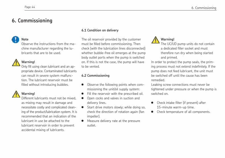
6. Commissioning
Note
Observe the instructions from the ma-
chine manufacturer regarding the lu-
bricants that are to be used.
Warning!
Only fill using clean lubricant and an ap-
propriate device. Contaminated lubricants
can result in severe system malfunc-
tion. The lubricant reservoir must be
filled without introducing bubbles.
Warning!
Different lubricants must not be mixed,
as mixing may result in damage and
necessitate costly and complicated clean-
ing of the product/lubrication system. It is
recommended that an indication of the
lubricant in use be attached to the
lubricant reservoir in order to prevent
accidental mixing of lubricants.
6.2 Commissioning
Observe the following points when com-
missioning the unit/oil supply system:
Fill the reservoir with the prescribed oil.
Open cocks and valves in suction and
delivery lines.
Start drive motors slowly; while doing so,
check the direction of rotation again (fan
impeller).
Measure delivery rate at the pressure
outlet.
Warning!
The UC/UD pump units do not contain
a dedicated filler socket and must
therefore run dry when being started
and primed.
In order to protect the pump seals, the prim-
ing process must not extend indefinitely. If the
pump does not feed lubricant, the unit must
be switched off until the cause has been
remedied.
Leaking screw connections must never be
tightened under pressure or when the pump is
switched on.
Check intake filter (if present) after
15-minute warm-up time.
Check temperature of all components.
6.1 Condition on delivery
The oil reservoir provided by the customer
must be illed before commissioning. Then
check (with the lubrication lines disconnected)
whether bubble-free oil emerges at the pump
body outlet ports when the pump is switched
on. If this is not the case, the pump will have
to be vented.
Page 45 EN7. Shutdown
7.1 Temporary shutdown
The described product can be temporarily shut
down by disconnecting the electrical, pneumatic,
and/or hydraulic supply connections.
The safety instructions in these assembly in-
structions must be observed when doing so.
If the product is to be shut down for an ex-
tended period of time, follow the instructions
in Chapter 3, "Transport, delivery, and storage,"
in these operating instructions.
To recommission the product, follow the in-
structions in the Chapters "Assembly" and
"Commissioning" in the assembly instructions
and operating instructions.
7.2 Permanent shutdown
If the product will be permanently shut down,
the local regulations and laws regarding the
disposal of contaminated equipment must be
observed.
Lubricants can contaminate soil and bodies of
water.
Warning!
Lubricants must be properly used and
disposed of. Observe the local regulations
and laws regarding the disposal of
lubricants.
The product can also be returned to SKF
Lubrication Systems for disposal, in which case
the customer is responsible for reimbursing the
costs incurred.
7. Shutdown

Page 46 EN 8. Maintenance
8. Maintenance
Warning!
Work on products that have not been
de-energized may result in bodily in-
jury. Assembly, maintenance and repair
work may only be performed on prod-
ucts that have been de-energized by
qualified technical personnel. The supply
voltage must be switched off before
opening any of the product's
components.
Products from SKF Lubrication Systems are
low-maintenance. However, all connections
and fittings must be regularly inspected for
proper seating to ensure proper function and
to prevent hazards from arising.
If necessary, the product can be cleaned using
mild cleaning agents that are compatible with
the product's materials (non-alkaline, non-soap).
For safety reasons, the product should be
disconnected from the power supply and the
hydraulic and/or compressed air supply.
It must be ensured that no cleaning agent
enters the interior of the product during
cleaning.
It is not necessary to clean the interior of the
product if the product is operated normally
and intercompatible lubricants are used.
The interior of the product must be cleaned if
incorrect or contaminated lubricant is acciden-
tally filled into the product. If this occurs,
please contact the Service department of SKF
Lubrication Systems for assistance.
Dismantling of the product or individual
parts thereof within the statutory war-
ranty period is not permitted and voids
any claims.
Only original spare parts from SKF
Lubrication Systems may be used.
Arbitrary alterations to products and
the use of non-original spare parts and
accessories are not permitted and nullify
the statutory warranty.
SKF Lubrication Systems shall not be held li-
able for damages resulting from improperly
performed assembly, maintenance and repair
work on the product.

Page 47 EN8. Maintenance
8.1 General information
The gear pumps function without mainte-
nance in principle. Upstream and downstream
filters must be cleaned in time or replaced on
a regular basis. Observe the readings on visual
and electrical contamination indicators, if
present.
Dirt deposits on the surface of the motor im-
pair cooling and must be removed regularly.
Only fill with clean oil. The purity of the
lubricants used is the decisive factor in
the service life of the pump and the lu-
bricated machinery elements.
Only add oil via the filler socket.

Page 48 EN
Warning!
Lubrication systems are pressurized
during operation. Lubrication systems
must therefore be depressurized before
starting assembly, maintenance or re-
pair work, or any system modifications
or system repairs.
9. Malfunction
The following tables provide an overview of
possible malfunctions and their causes.
Contact the Service department of SKF
Lubrication Systems if you cannot remedy the
malfunction.
Dismantling of the product or individual
parts thereof within the statutory war-
ranty period is not permitted and voids
any claims.
All assembly, maintenance and repair
work beyond this scope must be per-
formed by SKF Lubrication Systems
Service.
Only original spare parts from
SKF Lubrication Systems can be used.
Arbitrary alterations to products and
the use of non-original spare parts and
accessories are not permitted.
9. Malfunction
Warning!
Work on products that have not been
de-energized may result in bodily in-
jury. Assembly, maintenance and repair
work may only be performed on prod-
ucts that have been de-energized by
qualified technical personnel. The sup-
ply voltage must be switched off before
opening any of the product's
components.
Warning!
The hot surface of a motor may cause
burns. Motor surfaces may only be
touched with appropriate gloves or af-
ter the motor has been shut off for an
extended time.

Page 49 EN
Malfunction Cause Remedy
Pump does not deliver medium Motor stopped
Motor rotating in wrong direction
Coupling defective
Air drawn in (cavitation)
Oil too viscous
Check valve installed incorrectly
– Check electrical connections and reverse if necessary
– Check electrical connections and reverse if necessary
– Replace coupling
– Check fill level or oil feed
– Check proper sealing of suction line
– Fill with oil of permissible operating viscosity
– Rectify installation
Pump delivers too little medium Motor speed too low
Air drawn in
Leakage
– Check electrical connections and reverse if necessary
– See above
– Remedy leaks
– Check setting of pressure regulating valve
– Check screw connection and suction line
Pump noises too loud Intake pipe Ø too small – Increase intake pipe Ø or shorten suction line
– Fill with oil of permissible operating viscosity
9.1 Commissioning malfunctions
9. Malfunction
Warning!
In cases of functional failure, always make sure that all technical speciications have been
complied with in the existing operating conditions.

Page 50 EN 10. Accessories
10. Accessories
Series 1, UC and UD, adjustable
Series 1, UC and UD, non-adjustable
72
M10
x1
10
Pressure regulating valve, Series 1, adjustable
Application Operating pressure Order no.
UC/UD 0 - 20 bar 24-2103-2121
20 - 60 bar 24-2103-2122
37
M1
0x1
10
S W14
11
75
For tube Ø 6
Return flow connection for tube Ø 6
Cap plug
Pressure regulating valve, Series 1, fixed setting
Application Cracking pressure Order no.
UC/UD 10 bar 24-2103-2382
15 bar 24-2103-2383
25 bar 24-2103-2384
30 bar 24-2103-2384
35 bar 24-2103-2385
50 bar 24-2103-2386
60 bar 24-2103-2401
Sealing ring 95-1021-7603

Page 51 EN10. Accessories
Series 2 and 3, UC, adjustable
12
6
M30x1,5
47
,5
Pressure regulating valve, Series 2 and 3, adjustable
Application Operating pressure Order no.
UC 3 - 10 bar 24-2103-3076
10 - 15 bar 24-2103-3077
15 - 50 bar 24-2103-3078
40 - 100 bar 24-2103-3079
70 - 180 bar 24-2103-3080
100 - 250 bar 24-2103-3081
Cap plug
Sealing set FPMincluded in delivery

Page 52 EN
Series 2 and 3,
UC and UD, for line installation, adjustable
M1
8x1
,5
54
Ø31M
18
x1,5
13
6,5
63
M18x1,5
46
,5
Pressure regulating valve, Series 2 and 3, for line installation
Application Operating pressure Order No.
UC/UD 3 - 10 bar 24-2103-3088
10 - 15 bar 24-2103-3089
15 - 50 bar 24-2103-3090
40 - 100 bar 24-2103-3091
70 - 180 bar 24-2103-3092
100 - 250 bar 24-2103-3093
Screw unions Dimensions Order no.
GE screw connection M 18 x 1.5 (Ø 12) 412-433
GE screw connection M 18 x 1.5 (Ø 15) 96-0315-0058
Sealing ring A 18 x 22 DIN7603-A18x22-Cu
ScrewM 18 x 1.5 95-1518-0908
Warning!
When the pressure regulating valve is used
for line installation, the pump-side mounting
hole (M30x1.5) must be closed with a plug
Order number 44-1821-2194.
Cap plug
10. Accessories
Seling material FPM

Page 53 EN10. Accessories
UC/UD gear pump unit, Series 1
(ordered separately)
Description Order no.
Suction port:
GE screw connection G 3/8" - Ø 12 412-403W
GE screw connection G 3/8" - Ø 15 415-433W
Sealing ring G 3/8" DIN7603-A17x21-Cu
Pressure port:
GE screw connection G 1/4" - Ø 6 406-413W
GE screw connection G 1/4" - Ø 8 408-403W
GE screw connection G 1/4" - Ø 10 410-403W
GE screw connection G 1/4" - Ø 12 412-423W
Sealing ring G 1/4" DIN7603-A14x18-Cu
Fastening screw M6x20 DIN 912 DIN912-M6x20-8.8
Sealing ring for pressure
regulating valve
A10x13.5 95-1021-7603
UC/UD gear pump unit, Series 2
(ordered separately)
Description Order no.
Suction port:
GE screw connection G 1/2" - Ø 18 96-0218-0058
Sealing ring G 1/2" DIN7603-A21x26-Cu
Pressure port:
GE screw connection G 1/2" - Ø 12 412-453W
GE screw connection G 1/2" - Ø 15 96-0215-0058
GE screw connection G 1/2" - Ø 18 96-0218-0058
GE screw connection G 3/8" - Ø 12 412-403W
GE screw connection G 3/8" - Ø 15 415-433W
GE screw connection G 3/8" - Ø 18 96-0220-0058
Fastening screw M8x16 DIN 912 DIN912-M6x16-8.8
Fastening screw M8x30 DIN 912 DIN912-M8x30-8.8
Screw plug for unused pressure port:
Screw plug G 1/2" 95-0012-0908
Sealing ring DIN7603-A21x26-Cu
Screw plug G 3/8" 95-0038-0908
Sealing ring DIN7603-A17x21-Cu

Page 54 EN 10. Accessories
UC/UD gear pump unit, Series 3
(ordered separately)
Designation Dimension Size [l/min] Order No.
Suction port:
GE screw connection G 1/2" - Ø 22 UC/UD: 6; 8; 11.5 96-0223-0058
GE screw connection G 3/4" - Ø 28 UC/UD: 13.7 to 36 96-0229-0058
Pressure port:
GE screw connection G 1/2" - Ø 12 UD: 6 to 20.5 412-453W
GE screw connection G 1/2" - Ø 15 UC: 3.8 to 36 96-0215-0058
GE screw connection G 1/2" - Ø 18 96-0218- 0058
GE screw connection G 3/4" - Ø 12 UD: 26; 30; 36 412-463W
GE screw connection G 3/4" - Ø 15 96-0246-0058
GE screw connection G 3/4" - Ø 18 412-413W
GE screw connection G 3/4" - Ø 22 96-0222-0058
Fastening screw M 10 x 30 DIN 912 95-1030-0912
Fastening screw M 12 x 35 DIN 912 DIN912-M12x35-8.8
Screw plug for unused pressure port
Screw plug G 1/2" 95-0012-0908
Sealing ring DIN7603-A21x26-Cu
Screw plug G 3/4" 95-0034-0908
Sealing ring DIN7603-A27x32-Cu

Page 55 EN11. Spare parts
11. Spare parts
Arbitrary alterations and manufac-
ture of spare parts
Device rebuilding or modiication is only
permitted with manufacturer's agree-
ment. Original spare parts and acces-
sories, which are authorized by the
manufacturer, serve to ensure safety.
The use of other parts shall serve to
eliminate any liability for consequences
thereof.
FPM pump gasket sets
Series Type Size Order No.
1 UC/UD 0.06 ... 3 l/min 24-0404-2294
UC/UD 1.5; 2.0; 2.5 and 3 l/min 24-0404-2299 1)
2 UC 1 ... 10.8 l/min 24-0404-2334
UD 1 ... 10.8 l/min 24-0404-2337
3 UC 3.8 ... 11.5 l/min 24-0404-2320
UC 13.7 .. 20.5 l/min 24-0404-2321
UC 26 ... 36 l/min 24-0404-2322
UD 3.8 ... 11.5 l/min 24-0404-2328
UD 13.7 ... 20.5 l/min 24-0404-2329
UD 26 ... 36 l/min 24-0404-2330
1) Only applicable to pumps with keys 2847 B to 2850 B

951-170-022-EN
SKF Lubrication Systems Germany GmbH
2. Industriestrasse 4 ·68766 Hockenheim · Germany
Tel. +49 (0)62 05 27-0 · Fax +49 (0)62 05 27-101
www.skf.com/lubrication
SKF Lubrication Systems Germany GmbH
Motzener Strasse 35/37 ·12277 Berlin · Germany
PO Box 970444 · 12704 Berlin · Germany
Tel. +49 (0)30 72002-0 · Fax +49 (0)30 72002-111
www.skf.com/lubrication
The contents of this publication are the copyright of the publisher and may not be reproduced
in whole or in part without permission of SKF Lubrication Systems Germany GmbH. Every
care has been taken to ensure the accuracy of the information contained in this publica-
tion. However, no liability can be accepted for any loss or damage, whether direct, indirect
or consequential, arising out of use of the information contained herein.
All SKF products may be used only for their intended purpose as described in these as-
sembly instructions with associated operating instructions. If assembly/operating instruc-
tions are supplied together with the products, they must be read and followed. Not all lu-
bricants can be fed using centralized lubrication systems. SKF can, on request, inspect the
feedability of the lubricant selected by the user in centralized lubrication systems.
Lubrication systems and their components manufactured by SKF are not approved for use
in conjunction with gases, liquefied gases, pressurized gases in solution, vapors or such
fluids whose vapor pressure exceeds normal atmospheric pressure (1013 mbar) by more
than 0.5 bar at their maximum permissible temperature.
Hazardous materials of any kind, especially the materials classified as hazardous by CLP
Regulation EC 1272/2008, annex 1, parts 2-5, may be filled into SKF centralized lubrica-
tion systems and compo-nents and delivered and/or distributed with the such systems and
components only after consulting with and obtaining written approval from SKF.