Ubiquitous Environmental Control System (UECS) · 4 Attention . Please note the following...
54
1 Ubiquitous Environmental Control System (UECS) Application Communication Protocol Book For version 1.00-E10 June 9, 2012(English revision) (Based on September 1, 2010 Japanese version) Copyright 2010, The UECS Consortium Produced by: UECS-CCM Standardization Committee
Transcript of Ubiquitous Environmental Control System (UECS) · 4 Attention . Please note the following...

1
Ubiquitous Environmental Control System (UECS)
Application Communication Protocol Book
For version 1.00-E10
June 9, 2012(English revision) (Based on September 1, 2010 Japanese version)
Copyright 2010, The UECS Consortium Produced by: UECS-CCM Standardization Committee

2
Contents
Page
I. Introduction 3
II. Characteristics of
UECS Application Communication Protocol 5
III. Protocol for communication method of CCM 7
IV. Protocol of naming CCM identifier 36
V. Protocol for reserved CCM identifier 40
VI. Protocol for priority of action mode 51
VII. Other 54
Members of the UECS-CCM Standardization Committee, the UECS Consortium Chair Dr. Ken-ichiro YASUBA, National Institute of Vegetable and
Tea Science Mr. Yasumasa HAYASHI, Hortplan Corporation Dr. Hidehito KUROSAKI, National Institute of Vegetable and
Tea Science Dr. Takehiko HOSHI, Tokai University

3
I. Introduction
In the Ubiquitous Environmental Control System (UECS), installed equipment and sensors control a horticultural environment autonomously by decentralized communication of information. The communication by this protocol is defined based on the UECS Basic Communication Protocol Book version 1.00.
It is possible to collect information on climate control with sensors by constructing the system in accordance with the Communication Protocol Book. The naming conventions of the correspondence message and the method of communication, which are not provided in the Basic Communication Protocol Book, are provided by the Application Communication Protocol Book.
The device and software that communicate in accordance with this book are recognized by the UECS Consortium as equipment for Application Communication Protocol version 1.00-E10 (hereafter, called the “UECS device”).
It is possible to easily observe and control the UECS device in a greenhouse by sending and receiving UDP/IP packets on an Ethernet LAN that follows this protocol. Many people (from general enterprises to individual users) can develop practicable software for protected cultivation by acquiring the widespread programming techniques of personal computers. It seems that construction of the integrated environment control system can be achieved at a low price because special equipment and software become unnecessary in the UECS. Consequently, introducing the environmental control system in not only large-scale greenhouses but also small-scale ones such as a pipe house should be straightforward.
To control the environment, all introduced UECS devices must be able to communicate by the same method. The purpose of this protocol book is to provide a standard for controlling the environment and to clarify the standard for UECS devices.

4
Attention
Please note the following disclaimers for this book, which defines Application Communication Protocol “1.00-E10” of the Ubiquitous Environmental Control System (UECS). 1. This book shows the instructions to secure instrumentation control. However, even if the communication procedure of this book is mounted on a UECS device, instrumentation control is not guaranteed by the UECS Consortium. 2. The purpose of applying this protocol is to improve the earnings in plant production and to control the environment. However, this protocol does not guarantee the certainty of plant production, improved profits, and labor saving. 3. This protocol is not intended to be used in applications of nuclear power, aerospace, and medical treatment, for which high reliability is necessary. 4. The UECS Consortium does not accept any liability for damage indirectly or immediately caused by the content described in this book.

5
II.Characteristics of UECS Application Communication Protocol
This protocol provides a communication method to control an environment using a LAN. The device can control the environment in greenhouses autonomously by introducing equipment that can interpret information communicated by the mutual communication procedure provided by this protocol. UECS Application Communication Protocol “1.00-E10” has the following features.
1. Construction of a network for environmental control using Ethernet and TCP/IP The Ethernet LAN, which presently is in widespread use, provides the
communication for the UECS. Therefore, a UECS network can be constructed at a low price using hubs and routers already on the market, and the network can easily be connected to the Internet. The network corresponds only to IPv4 in the present version. 2. Decentralized system All UECS devices are mounted in the communication facility, so information on the
equipment can be shared easily. A device using the UECS protocol is called a node. Information can be transmitted between nodes and the node can be operated remotely using the communication protocol. Moreover, a decentralized autonomous system that operates by node self-judgment can be constructed. In addition, a computer for centralized control can enable centralized control of the nodes. 3. The use of UDP communication The user datagram protocol (UDP) is used in the UECS for the communication of
information. Information is transmitted by broadcasting, which is one of the functions of the UDP. The use of broadcast enables the widespread, high-speed exchange of information. 4. Information exchange with high readability by XML
The information sent from a node is described in Extensible Markup Language (XML), established by the World Wide Web Consortium, so the information is offered with high readability.
5. Common Communication Message

6
The Common Communication Message (CCM) is an elementary unit of information exchanged on the UECS network. The CCM is composed of an attribute and its value. Both the attribute and the unit of value are defined by this protocol. Even if the vendor different, information can be exchanged using the defined CCM. An example of a CCM transmitted from a node that measures soil temperature is shown.
<?xml version="1.0"?>
<UECS ver="1.00-E10">
<DATA type="SoilTemp.mIC" room="1" region="1" order="1" priority="15">23.0</DATA>
<IP>192.168.1.64</IP>
</UECS>
“SoilTemp.mIC” in the above CCM expresses the soil temperature as the information and the value of 23.0 as the soil temperature measurement. A node that can interpret this CCM can be used to control the environment.
Not all CCMs are used for data transmission; these CCMs are shown in a later
chapter. The CCM can have a naming protocol that enables the vendor to make original CCMs. In this case, it is necessary to expand the meaning of a new CCM. 6. Specification of useful range of the CCM The range of transmission of information can be defined by setting the room, the
region, and the order, each of which is an attribute value of the CCM. For example, when an instruction to open the ventilation window is sent, processing such as opening a specific window or opening windows in the entire greenhouse becomes possible.

7
III.Protocol for communication method of CCM Communication among nodes in the UECS is done by a method using the UDP
packet. The UDP packet includes an XML formatted sentence described by a stylized communication message. This stylized message is the CCM in the UECS. The information represented by the CCM includes the following: measuring value, variable for node status, information of the direction, setting parameter, target value, and so on. The communication of the CCM contains information other than that for immediate control. For example, saving the node’s history log and information of the node setting are examples of communication information made available through the CCM.
1. Outline 1) Kinds of CCM communication
CCM is communicated by the UDP on the transport layer of the OSI reference model. The communication uses either a broadcast or a unicast connection.
The relationship between the kind of CCM and the communication method is shown in Table 3-1.
Table 3-1 The relationship between the kind of CCM and the communication method
Grouping Port number Description Name of tag Communication of
general information UDP16520 data transfer CCM <DATA>
data request CCM <REQUEST> Search for sender
CCM UDP 16521 search sender CCM <SEARCH>
response sender CCM <SERVER> (Reserved area) UDP
16522–16528 (reserved)
Node scan
UDP 16529 request node scan CCM <NODESCAN> response node scan CCM <NODE>
CCM scan
UDP 16529 request ccm scan CCM <CCMSCAN> response ccm scan CCM <CCMNUM>
and <CCM>

8
2) Format CCM is described in accordance with the UECS Basic Protocol Book version 1.00. Basic configuration <?xml version="1.0"?>
<UECS ver="1.00-E10">
<!-- specific descriptions -->
</UECS>
This protocol has the following limitations that are not the same as those of the basic protocol. Restriction of the character code
The character code of the CCM is 8 bit US ASCII code (ISO 646-1991, with the addition of a “0” bit to the most significant bit). Other character codes greater than 2 bytes in length, such as UTF and Shift JIS, are not available. The UECS nodes distinguish between upper case characters and lower case characters. We can use CR (Carriage Return) and/or LF (Line Feed) characters to insert line feeds in the description in the CCM communication. In general, characters from 0x20 (hexadecimal value) to 0x7f plus CR and LF are used. The attribute value must be enclosed in double quotes. The maximum size of the whole packet is limited to less than 480 bytes. Spaces inserted inside double quotes of the attribute are interpreted as characters and are not ignored. The recommended notation is as follows:
Recommended notation (Line breaks are represented by downward arrows)
<?xml version="1.0"?>↓
<UECS ver="1.00-E10">↓
<DATA type="SoilTemp.mIC" room="1" region="1" order="1" priority="1">23.5</DATA>↓
<IP>192.168.1.64</IP>↓
</UECS>↓

9
Recommended notation for empty-element tag (Line breaks are represented by downward
arrows) <?xml version="1.0"?>↓ <UECS ver="1.00-E10">↓ <SEARCH type=" SoilTemp.mIC " room="1" region="1" order="1"/>↓ </UECS>↓
The following notation for an empty-element tag in this protocol is prohibited.
Prohibited notation for empty-element tag (Line breaks are represented by downward
arrows) <?xml version="1.0"?>↓ <UECS ver="1.00-E10">↓ <SEARCH type=" SoilTemp.mIC " room="1" region="1" order="1"></SEARCH>↓ </UECS>↓
Limitation of packet size
The UDP packet has a theoretical maximum size of 65515 bytes. But, the embedded microcomputers need to do a lot of processing with limited resources, and so the packet size is usually limited by the router setting to less than approximately 512 bytes. The packet size for CCM communication per one time is determined to be less than 480 bytes. Limitation of number of tags Tags except the <CCM> tag in the response CCM scan are limited to one time per <UECS> tag. Therefore, two or more tags in the following <UECS> tag are not valid. <DATA> <REQUEST> <SEARCH> <SERVER> <NODESCAN> <NODE> <CCMSCAN>

10
Reserved attribute values in the tags In CCM communication, the attribute values shown in Table 3-2 are used. In
addition to the attributes defined by the UECS Basic Protocol Book, the priority attribute is used as a reserved attribute. If the description of an attribute other than the type attribute and the priority attribute is omitted, the omitted attribute value is interpreted as 0.

11
Table 3-2 Reserved attributes used in the CCM Attribute name
Definition Description
Type
Type identifier Uses more than 3 and less than 19 alphanumeric characters.※1
CCM compatibility is secured by the identifier being standardized. This attribute is required.
Room
Room number The highest division is a number to distinguish rooms (greenhouses). Integer 0 to 127. The number 0 indicates whole rooms. This attribute is omissible. If omitted, the value is 0.
Region
Region number A number to distinguish some regions or systems in a room. Especially, the attribute is used to distinguish a measurement control system. Integer 0 to 30000. The number 0 indicates whole regions or systems. This attribute is omissible. If omitted, the value is 0.
Order
Order number A number to distinguish some divisions in a region. Especially, the attribute is used to distinguish the same kind of components in a region. Integer 0 to 30000. The number 0 indicates whole divisions or components. This attribute is omissible. If omitted, the value is 0.
Priority
Priority number If CCMs with intrinsically matched attributes (defined later) are received from some UECS nodes, the priority of information of the CCMs is determined by this value. Integer 0 to 30. This attribute is required.
※1 The use of characters such as “a”–“z”, “A”–“Z”, “0”–“9”, “_” (underscore) and “.” (period) is permitted.

12
The priority number is used to determine the priority of information sent from some UECS nodes for deciding their own action. The detail of the priority number is shown in Table 3-3.
Table 3-3 Relationship between value of priority attribute and priority of receiving information Value Detail 0–29 Information of a CCM with a lower priority number from 0 to 29 has
higher priority. These values are used in the communication of the data transfer CCM with Level A and Level S. “Level” is described later in detail.
30 This attribute is set at 30 without managing the priority of the CCM. This value is used in the communication of the data transfer CCM with Level B. “Level” is described later in detail.

13
2. General data transfer method General information concerning sensor measurements, node status, and instructions for operation of the nodes are exchanged with the data transfer CCM and the data request CCM. A data transfer CCM is transmitted by a UDP broadcast, and a data request CCM is transmitted by unicast. If the data request CCM is sent by broadcast, the data transfer CCM could be received at unexpected nodes. So, the data request CCM must be used by unicast. The response of sending the data transfer CCM to the receiving data request CCM must be done in the case of a data transfer CCM with only Level B (not Level A and Level S). Levels are described later in this chapter. (1) Variety
data transfer CCM data request CCM
(2) Detail

14
Table 3-4 Data transfer CCM Kind Data transfer CCM
Aim Communication of general information of environmental control
Protocol UDP broadcast Port UDP 16520 port
Example <?xml version="1.0"?> <UECS ver="1.00-E10"> <DATA type="SoilWater.mIC" room="1" region="1" order="1" priority="1">23.5</DATA> <IP>192.168.1.25</IP>
</UECS> Supplement <DATA>tag
The value of the data tag indicates information concerning the environmental control in the greenhouse. Only numbers are permitted. Please refer to Table 3-2 for more information about attribute values.
Type: CCM identifier. It is required. Room: Room number. If omitted, the value is 0. Region: Region number. If omitted, the value is 0. Order: Order number. If omitted, the value is –0. Priority: Priority number. It is required.
<IP>tag The value of the IP tag indicates the IP address of this node. * Condition of sending the data transfer CCM with Level B If the data request CCM with the same type identifier and with the attributes of the
room region and order are associated with the node (intrinsically matched attributes; see page 19) is received, and the data transfer CCM (sender) with Level B corresponding to the received data request CCM is registered at the node, the node responds by sending the data transfer CCM.

15
Table 3-5 Data request CCM Kind Data request CCM Aim Communication of request for sending a data transfer CCM with Level B Protocol UDP unicast Port UDP 16520 port Example <?xml version="1.0"?>
<UECS ver="1.00-E10"> <REQUEST type="SoilWater.mIC" room="1" region="1" order="1"/> </UECS>
Supplement <REQUEST>tag Please refer to Table 3-2 for more information about attribute values.
Type: CCM identifier. It is required. Room: Room number. If omitted, the value is 0. Region: Region number. If omitted, the value is 0. Order: Order number. If omitted, the value is 0.
* Condition of sending the data transfer CCM with Level B If the data request CCM with the same type identifier and with the attributes of room region and order associated with the node (intrinsically matched attributes; see page 19) is received, and the data transfer CCM (sender) with Level B corresponding to the received data request CCM is registered at the node, the node responds by sending the data transfer CCM.

16
(3) Timing of sending the data transfer CCM The timing of sending the data transfer CCM depends on the importance of that information, and it is divided into three types (Level A, Level B, and Level S). >Level A
The CCM with information of importance and utilization is classified as Level A. The CCM with this level is transmitted periodically by broadcast. The value of the priority attribute in the <DATA> tag must be set from 0 to 29 as an integer in the case of sending. But the valid range of this attribute is from 0 to 30 in receiving. If many nodes are connected in the LAN for the UECS, network traffic becomes worse. So, the frequency for the transmission period of this level CCM must be considered carefully, and it is recommended that regular intervals be as long as possible. Table 3-6 Kind of transmission interval of the data transfer CCM with Level A
>Level B
If the node receiving the data request CCM with the reserved attribute values is related to the sending node (intrinsically matched attributes; see page 19), it sends the data transfer CCM. The data request CCM must be sent by UDP unicast, and the data transfer CCM must be sent by broadcast. The value of the priority attribute is only 30 in the case of sending, and the valid range of this value is from 0 to 30 in the case of receiving.
This level of the CCM is intended to be used for receiving the configuration value of a node, and sensor readings are used less frequently. The valid time of received information for the CCM with Level B is not managed in principle. That is, received
Regular transmission
interval
Immediate send due to changing
value
Notation Value of priority
attribute
Valid time of received information for CCM
1 sec no A-1S-0
Sender 0–29
Receiver 0–30
3 sec yes A-1S-1
10 sec no A-10S-0
30 sec yes A-10S-1
1 min no A-1M-0
180 sec yes A-1M-1

17
information is processed according to the receiving order. When the node has not even received a data request CCM, transmission of the CCM at this level is allowed. However, the valid time of received information is not managed and the received information is processed according to the receiving order in the case of receiving the CCM with Level B.
Table 3-7 Kind of transmission interval of data transfer CCM with Level B
> Level S
The data transfer CCM with Level S is used to perform remote manipulation and remote operation of another node. When the node is controlled by remote manipulation or remote operation, the data transfer CCM of Level S with an instruction must be sent by a regular transmission interval. However, if remote manipulation and remote operation are not used, this CCM is not sent. If the period from the last transmission is below the regular transmission interval and one wants to change the previous instruction contents, it is permitted to send a new CCM with a new instruction.
The CCM for remote manipulation is used to operate nodes from an electrical switch node. The CCM for remote operation is used to control the environment integrated by a personal computer and the controller for integrated environmental control.
When the data transfer CCM concerning remote operation and remote manipulation are not received during the regular transmission interval, remote operation and remote manipulation of the node are judged to be invalid. Chapter 5 shows the detail for the remote operation CCM and the remote
manipulation CCM.
Regular transmission
interval
Immediate send due to
changing value Notation
Value of priority attribute
Valid time of received
information for the CCM
Not determined
no B-0 Sender 30
Receiver 0–30
Valid time is not managed yes B-1

18
Table 3-8 Kind of transmission interval of the data transfer CCM with Level S
> Other Level The definition of a node’s own data transfer level other than the above is permitted.
No conflicts should arise against the abovementioned levels.
Kind of CCM Regular
transmission interval
Notation Value of priority
attribute
Valid time of received
information for CCM
Remote operation
Remote Operation: 1 sec
No operation: No send
S-1S-0
Sender 0–29
Receiver 0–30
3 sec
Remote manipulation
Remote Manipulation:
1 sec No manipulation:
No send
S-1M-0
Sender 0–29
Receiver 0–30
180 sec

19
(4) Selection method of valid CCM information When the node receives some data transfer CCMs with the same CCM identifier
(type attribute in <DATA> tag), it is judged as a valid CCM from the attribute in the <DATA> tag, the valid time of the received information, and the IP address of the sender. Details are shown in the flowchart of Fig. 3-1.

20
bCCM: CCM registered as receiver vCCM: valid CCM in last received as bCCM registered rCMM: received CCM
Fig. 3-1. Flowchart for selection method of the valid CCM

21
Table 4-2 (Basic) Order of acceptance priority by the attribute values in the received
CCM*1
Order of priority*3 Room
attribute value
Region attribute
value
Order of attribute value
1 Accordance*2 Accordance Accordance 2 Accordance Accordance 0 3 Accordance 0 Accordance 4 Accordance 0 0 5 0 Accordance Accordance 6 0 Accordance 0 7 0 0 Accordance 8 0 0 0
*1: This table is referenced from the UECS Basic Communication Protocol Book version 1.00.
*2 “Accordance” means that the node’s attribute value is in accordance with the attribute value of the received CCM.
*3 If a CCM that does not conform to the table is received by the node, the node disregards the CCM.
The completely same values as the type, room, region, and order attributes of the
received CCM registered in the node are called “closely matched attributes.” The values of the attributes are shown in column number “1” of the order of priority in Table 4-2 (Basic).
Either closely matched attributes or attribute values in the case that the room, region and order attributes are either zero or in accordance with the received CCM registered in the node are called “intrinsically matched attributes.” The values of the attributes are shown in column number “1” to “8” of the order of priority in Table 4-2 (Basic).
Some examples are provided to show the method to decide the selection of the valid CCM in the case of receiving CCMs. It is assumed that a node exists for automatic irrigation, and the attribute values of the room, region, and order of this node are set as 1, 2, and 3, respectively. In addition, this node starts irrigating after receiving the CCM (type attribute “SoilWater.WC”) conveying that the soil water content is low from the node for measuring the soil status,

22
and this CCM is registered as a received CCM with Level A-10S-0.
The assumption: 1. The attribute values of the irrigation node were set as room=”3” region=”2” order=”1”. 2. The CCM with the CCM identifier of “SoilWater.mWC” was registered as a received CCM with Level A-10S-0 at the irrigation node. 3. The irrigation node starts irrigating in the case of receiving a value under 50 of “SoilWater.mWC”.

23
Example 1 Ranking
of validity
Received CCM during 10 sec
1
<?xml version="1.0"?>
<UECS ver="1.00-E10">
<DATA type="SoilWater.mIC" room="3" region="2" order="1" priority="15">45</DATA>
<IP>192.168.1.80</IP>
</UECS>
2
<?xml version="1.0"?>
<UECS ver="1.00-E10">
<DATA type="SoilWater.mIC" room="3" region="2" order="1" priority="20">55</DATA>
<IP>192.168.1.81</IP>
</UECS>
3
<?xml version="1.0"?>
<UECS ver="1.00-E10">
<DATA type="SoilWater.mIC" room="3" region="2" order="0" priority="20">65</DATA>
<IP>192.168.1.82</IP>
</UECS>
Clarification: In the case of receiving the above three CCMs during 10 sec, the valid CCM is the CCM
of the top field because of the lowest priority attribute. In comparison with the CCMs of the middle
and bottom fields, the bottom field CCM has a lower validity with “0” as the order value, with
reference to Table 4-2 (Basic).

24
Example 2 Ranking
of validity
Received CCM during 10 sec
1
<?xml version="1.0"?>
<UECS ver="1.00-E10">
<DATA type="SoilWater.mIC" room="3" region="2" order="0" priority="15">45</DATA>
<IP>192.168.1.80</IP>
</UECS>
2
<?xml version="1.0"?>
<UECS ver="1.00-E10">
<DATA type="SoilWater.mIC" room="3" region="0" order="1" priority="15">55</DATA>
<IP>192.168.1.81</IP>
</UECS>
3
<?xml version="1.0"?>
<UECS ver="1.00-E10">
<DATA type="SoilWater.mIC" room="3" region="0" order="1" priority="15">65</DATA>
<IP>192.168.1.82</IP>
</UECS>
Clarification: In the case of receiving the above three CCMs during 10 sec, the CCM with the top field
has the highest validity. Because these three CCMs have the same priority value, the validity of the
CCM is decided with reference to Table 4-2 (Basic). The CCMs of the middle and bottom fields have all
the same attribute values, so the CCM of the middle field has higher validity because of the lower IP
address (an error status appears in the situation of deciding the validity of the CCM according to the
IP address).

25
Example 3 Ranking
of validity
Received CCM during 10 sec
1
<?xml version="1.0"?>
<UECS ver="1.00-E10">
<DATA type="SoilWater.mIC" room="3" region="2" order="0" priority="30">45</DATA>
<IP>192.168.1.80</IP>
</UECS>
2
<?xml version="1.0"?>
<UECS ver="1.00-E10">
<DATA type="SoilWater.mIC" room="3" region="0" order="1" priority="30">55</DATA>
<IP>192.168.1.81</IP>
</UECS>
3
<?xml version="1.0"?>
<UECS ver="1.00-E10">
<DATA type="SoilWater.mIC" room="3" region="0" order="1" priority="30">65</DATA>
<IP>192.168.1.82</IP>
</UECS>
Clarification: In the case of receiving the above three CCMs with Level B (because of the “30” priority
value) during 10 sec, the validity of the CCMs is interpreted as the same as that in Example 2. All
information is ineffective 10 sec after receiving. This ranking method is not recommended by the
UECS Consortium.
Next, “SoilWater.mWC” is registered as a received CCM of Level B.
The assumption: 1. The attribute values of the irrigation node are set as room=”3” region=”2” order=”1”. 2. The CCM with CCM identifier of “SoilWater.mWC” was registered as the received CCM with Level B-1 at the irrigation node. 3. The irrigation node starts irrigating in the case of receiving a value under 50 of “SoilWater.mWC”.

26
Example 4 Ranking Received CCM
Received
order
<?xml version="1.0"?>
<UECS ver="1.00-E10">
<DATA type="SoilWater.mIC" room="3" region="2" order="1" priority="30">45</DATA>
<IP>192.168.1.80</IP>
</UECS>
<?xml version="1.0"?>
<UECS ver="1.00-E10">
<DATA type="SoilWater.mIC" room="3" region="2" order="1" priority="30">55</DATA>
<IP>192.168.1.81</IP>
</UECS>
<?xml version="1.0"?>
<UECS ver="1.00-E10">
<DATA type="SoilWater.mIC" room="3" region="2" order="0" priority="30">65</DATA>
<IP>192.168.1.82</IP>
</UECS>
Clarification: In the case of registering the CCM with Level B, the information of the CCM is handled
according to the received order. However, the Level B CCM is intended to use the correspondence of
the measuring data without controlling the environment and the configuration value of the device.
The use of this level CCM is not recommended for controlling the environment.

27
Example 5 Ranking Received CCM
Received
order
<? xml version="1.0"?>
<UECS ver="1.00-E10">
<DATA type="SoilWater.mIC" room="3" region="2" order="1" priority="26">45</DATA>
<IP>192.168.1.80</IP>
</UECS>
<? xml version="1.0"?>
<UECS ver="1.00-E10">
<DATA type=" SoilWater.mIC" room="3" region="2" order="1" priority="30">55</DATA>
<IP>192.168.1.81</IP>
</UECS>
<? xml version="1.0"?>
<UECS ver="1.00-E10">
<DATA type="SoilWater.mIC" room="3" region="2" order="0" priority="30">65</DATA>
<IP>192.168.1.82</IP>
</UECS>
Clarification: The CCM of the top field is Level A or S because of the “26” priority value. However, the
information of the CCM is handled according to the received order because of registration as the
received CCM of Level B. This ranking method is not recommended by the UECS Consortium.

28
3. CCM search method Both the sender search CCM and the sender response CCM are used to search the
node registered for the data transfer CCM with Level B as the sender. The Level B CCM is not sent periodically. For getting information of the CCM of this level, the IP address of the sender of the CCM must be obtained by correspondence with the sender search CCM and the sender response CCM. The node sends the data request CCM to the obtained IP address and must wait for the sending data transfer CCM from the sender node. This process is shown in Table 3-2. Fig. 3-2 Process of the use of the data transfer CCM with Level B (1) Variety
Sender search CCM Sender response CCM
29
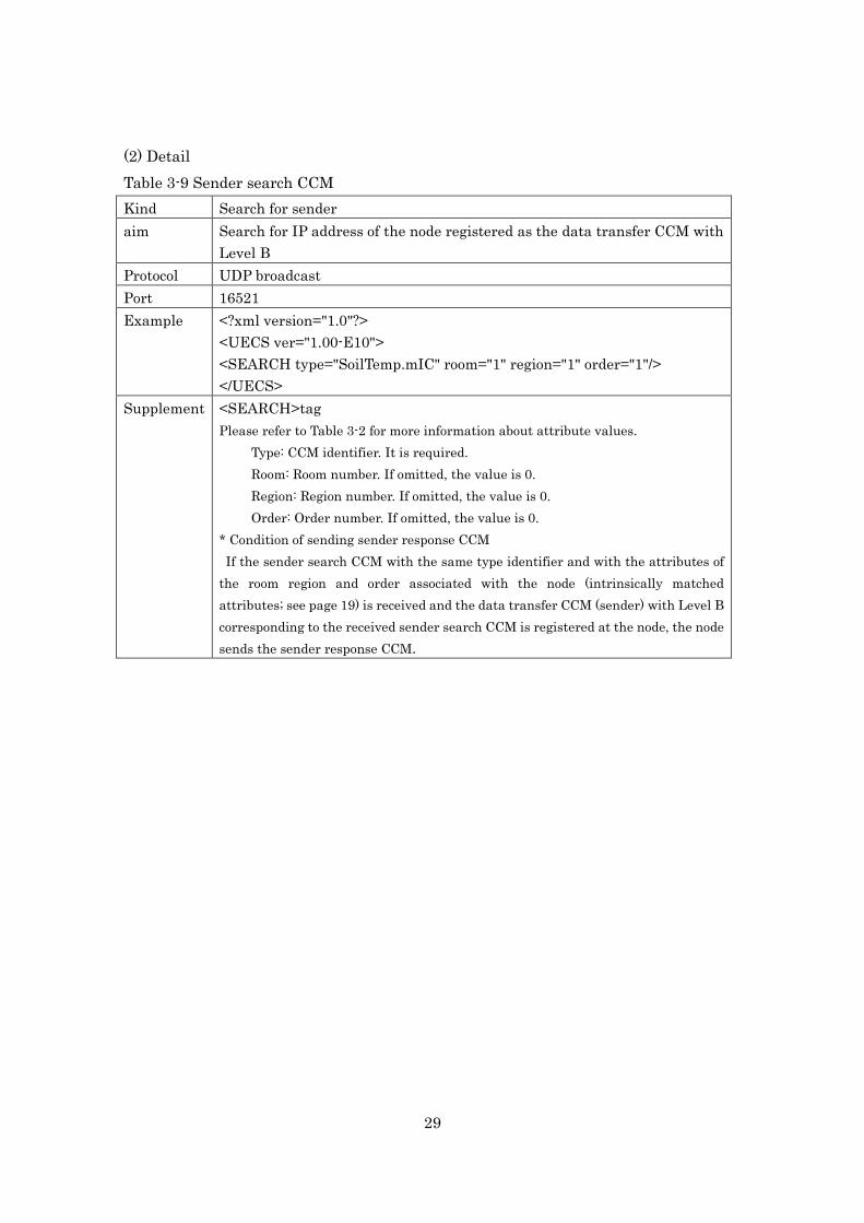
(2) Detail Table 3-9 Sender search CCM Kind Search for sender aim Search for IP address of the node registered as the data transfer CCM with
Level B Protocol UDP broadcast Port 16521 Example <?xml version="1.0"?>
<UECS ver="1.00-E10"> <SEARCH type="SoilTemp.mIC" room="1" region="1" order="1"/> </UECS>
Supplement <SEARCH>tag Please refer to Table 3-2 for more information about attribute values.
Type: CCM identifier. It is required. Room: Room number. If omitted, the value is 0. Region: Region number. If omitted, the value is 0. Order: Order number. If omitted, the value is 0.
* Condition of sending sender response CCM If the sender search CCM with the same type identifier and with the attributes of
the room region and order associated with the node (intrinsically matched attributes; see page 19) is received and the data transfer CCM (sender) with Level B corresponding to the received sender search CCM is registered at the node, the node sends the sender response CCM.

30
Table 3-10 Sender response CCM Kind Response from sender Aim Informed IP address of sender of Level B CCM Protocol UDP broadcast Port 16521 Example <?xml version="1.0"?>
<UECS ver="1.00-E10">
<SERVER type="SoilTemp.mIC" room="1" region="1" order="1"
priority="1">192.168.1.25</SERVER>
</UECS> Supplement <SERVER>tag
Please refer to Table 3-2 for more information about the attribute values. Type: CCM identifier. It is required. Room: Room number. If omitted, the value is 0. Region: Region number. If omitted, the value is 0. Order: Order number. If omitted, the value is 0.
* Condition of sending the sender response CCM If the sender search CCM with the same type identifier and with the attributes of the room region and order associated with the node (intrinsically matched attributes; see page 19) is received and the data transfer CCM (sender) with Level B corresponding to the received sender search CCM is registered at the node, the node sends the sender response CCM.

31
4. Scanning node information Both the node scan request CCM and the node scan response CCM are used to obtain
the node original information. (1) Variety
node scan request CCM node scan response CCM
(2) Detail Table 3-11 Node scan request CCM Kind Request for node scan Aim Request of sending node scan response CCM Protocol UDP broadcast or UDP unicast Port UDP 16529 Example <?xml version="1.0"?>
<UECS ver="1.00-E10"> <NODESCAN/> </UECS>
Supplement If the node receives a node scan request CCM, it must respond to the node scan response CCM.

32
Table 3-12 Node scan response CCM Kind Response for node scan request Aim Informed ordinal information for node Protocol UDP unicast Port 16529 Example <?xml version="1.0"?>
<UECS ver="1.00-E10"> <NODE> <NAME>ETH-01</NAME> <VENDER>UECSLab Inc.</VENDER> <UECSID>1234567890AB</UECSID> <IP>192.168.1.25</IP> <MAC>32613C4EB605</MAC> </NODE> </UECS>
Supplement <NAME>tag Device name <VENDOR>tag Maker name <UECSID>tag ID number published by the UECS Consortium <IP>tag IP address <MAC>tag Mac address * If the node receives the node scan request CCM, it must respond with the node scan response CCM. The max size of the UDP packet is 480 bytes.

33
5. Scanning CCM information Both the ccm scan request CCM and the ccm scan response CCM are used to obtain
the detail information of the data transfer CCM registered at the node. (1) Variety
ccm scan request CCM ccm scan response CCM
(2) Detail Table 3-13 ccm scan request CCM Kind Request for node scan response CCM Aim Request of sending ccm scan response CCM Protocol UDP unicast Port 16529 Example <?xml version="1.0"?>
<UECS ver="1.00-E10"> <CCMSCAN page="1"/> </UECS>
Supplement <CCMSCAN>tag Page: page number for requesting page to ccm scan response CCM. If page attribute is omitted, the page attribute is 1. * If the node receives the ccm scan request CCM, it must respond with the ccm scan response CCM. The max size of the UDP packet is 480 bytes.

34
Table 3-14 ccm scan response CCM Kind Response for ccm scan request CCM Aim Inform with detail information of the data transfer CCM.
Protocol UDP unicast Port 16529
Example <?xml version="1.0"?>
<UECS ver="1.00-E10">
<CCMNUM page="1" total="1">2</CCMNUM >
<CCM No="0" room="1" region="1" order="1" priority="1" cast="1" unit="C" SR="S"
LV="A-10S-0">InAirTemp</CCM>
<CCM No="1" room="1" region="1" order="1" priority="1" cast="0" unit="%" SR="S"
LV="B-1">WaterContent.mIC</CCM>
</UECS> Supplement <CCMNUM>tag
CCMNUM tag includes two attributes. Page: page number in total pages. It is required. Total: total number of pages. It is required. The value of this tag indicates the number of CCM tags in this page.
<CCM>tag CCM tag includes these attributes.
No: sequential serial number of CCM. It is required. Room: room number. It is required. Region: region number. It is required. Order: order number. It is required. Priority: priority number. It is required. Cast: Number of decimal places. If the value of the item is 0, the value is always
an integer. It is required. Unit: unit. It is required. SR:sender (S) or receiver (R). It is required. LV:data transfer level. It is required. The value of the CCM tag indicates the ccm identifier (type attribute in
data tag). * If the node receives the ccm scan request CCM, it must respond with the ccm scan response CCM. The max size of the UDP packet is 480 bytes. The page number is used to divide information over 480 bytes.

35
6. Attention For authorization from the UECS consortium that the communication method of the
developed UECS node and of the software is in accordance with the rules of this protocol book, it must be certified that the communication method of this book is implemented in the developed node with accurate software. The implementation of the correspondence procedure from this protocol book must conform to the communication rule and it must be confirmed that it is a correct method within the range of this book. However, it is a precondition that an enhanced part of this protocol does not obstruct the communication rule for recognizing the implemented communication method. The UECS Consortium is not responsible for system problems in cultivating crops
that occur in the system with equipment recognized by the consortium.

36
xxx.kNN
kNN
IV.Protocol of naming CCM identifier The CCM identifier is one of the basic attribute values, and this important attribute
reveals the kind of information. This attribute is used in many kinds of CCMs, such as the data transfer CCM. This chapter shows the protocol of naming the CCM identifier. The identifiers must be named according to the naming protocol presented in this chapter (except for the reserved CCM identifiers presented in the next chapter).
1. Format of the CCM identifier The identifier is composed to two parts: a node type name and an information name.
One period “.” appends these two parts. But, the node type name is omitted in the case that the CCM identifier is a reserved CCM identifier shown in the next chapter.
2. Naming of the node type The node type name is composed of one lowercase letter that represents a major
division of the node and two uppercase letters that represent the kind of node.
1) Major division of node
The letters for the major divisions of nodes were determined according to the rules shown in Table 4-1. Table 4-1 Letters for the major divisions of nodes
Letter Division Example
a Actuator node heater, ventilation window, fan
c Controller node switch, console
m Measurement node device of measurement of all kinds of
information concerning protected
horticulture
x Other node
Node type name Information name
Major division
Kind of node

37
2) Kind of node The kind of node is recognized as a symbol for the same kind of UECS device with
the same functionality across different manufacturers. The following symbols are defined in this chapter.
AH: heater of air using warm air WH: heater of air using hot water EH: heater of air using heating wire RV: device for opening and closing roof window CO: device for opening and closing curtain SV: device for opening and closing side window VF: device for controlling ventilation fan CF: device for controlling circulation fan MF: fogging device, device for mist and fan PF: device for pad and fan HP: heat pump EX: heat exchange device RH: heater of root area NM: device for controlling nutrient NB: device for planting bed OC: measuring device for meteorological condition out of greenhouse IC: measuring device for meteorological condition in greenhouse SL: device for supplemental light LC: lighting device for controlling day length CD: controller for CO2 VM: spreader of pesticide using smoking or evaporation SW: electrical switch SC: step controller (simplified console) MC: controller for integrative environmental control DB: database, data station CC: calculating device without sensing LI: device for monitoring parameter concerning crop HM: device for quantity of harvest WT: input device for information of working WV: device of controlling vehicle for agriculture XX: other devices
Other symbols can be confirmed, if necessary.

38
3.Notes for naming CCM identifier The CCM identifier is used to define the meaning of the CCM, so defining the same identifier with different meanings causes a big problem when operating the UECS system. When the developer defines a unique CCM identifier, that developer has a duty to notify the user of the information shown, as shown in Table 4-2.
It is recommended that the XML formatted file described for information of the CCM identifier (such as example in Table 4-3) is sent to the UECS Consortium.
Item Detail Example
CCM identifier Type attribute (see Table 3-2). RootTemp.mMC
Sender/
receiver
This parameter indicates whether the node is the sender
or receiver for this CCM.
sender
Interval of
communication
Expression for transmission interval (see Tables 3-6 and
3-7).
A-10S-0
Unit Unit of the value of the CCM. For example, this area is
“%” in the case that the CCM with this CCM identifier
expresses relative humidity.
C
Precision Number of decimal places. If the value of the item is 0,
the value of the CCM with this CCM identifier is always
expressed as an integer value.
1
Expression in
English
English expressions corresponding to this CCM
identifier.
Medium
temperature
Detail
information
A detailed description of the information of the CCM
with this CCM identifier.
Measuring
medium
temperature
using thermistor

39
Table 4-3 Example of XML formatted file described for information of the CCM identifier Example <?xml version="1.0" encoding=”UTF-8”?>
<UECS ver=”1.00-E10”>
<CCM cast=”1” unit=”C” SR=”S” LV=”A-10S-0” exp=”Medium temp” detail=”Measuring medium temperature with thermistor”
>RootTemp.mIC</CCM>
<CCM cast=”1” unit=”dS m-1” SR=”S” LV=”A-10S-0” exp=”electric conductivity” detail=”electric conductivity of root area”
>RootEC.mIC</CCM>
</UECS>
Attribute of CCM tag (see Table 4-2)
cast: precision Unit: unit SR: sender/receiver LV: interval of communication Exp: expression in English Detail: detail information
Attention ・File name is free to decide, but “.xml” must be used as the extension. ・The length of the “detail” attribute must be 30 characters or less.
40
V.Protocol for Reserved CCM Identifier There are some important CCMs among data transfer CCMs, so the identifier name
(called the reserved CCM identifier), the ideal interval of receiving the CCM, and the valid time from the receiving CCM are defined in this chapter. The unit of information of the CCM concerning the sensor node is defined, too. When the developer defines his or her own CCM identifier, the use of a reserved CCM identifier as the new CCM identifier is prohibited. If the CCM using the same CCM identifier and different unit (e.g., units of kWm-2, Wm-2, cal s-1m-2 in the case of solar radiation) is sent from several UECS nodes, it is impossible to determine the received information accuracy. Thus, an important CCM has a special identifier, and it is necessary to manage the use of that CCM. The reserved CCM identifier facilitates the operation of devices by different developers in the same UECS system. If the CCM of solar radiation in the greenhouse with a unit of “W m-2” is necessary, a CCM identifier other than the reserved CCM identifier must be used. If characters for the kind of node are added to the end of the reserved CCM identifier, it is available (for example, “InRadiation.mIC” as the CCM identifier is permitted).

41
1.Condition CCM(cnd.kNN) The condition CCM (cnd.kNN) must be registered as a “sender” data transfer CCM (see Chapter III). The CCM represents the current condition of the node (such as error information, identification of forces such as switch operation and autonomous operation). The value of the CCM is represented by a length of 32 bits, and each bit of the binary representation of this value shows the condition of the UECS node. Table 5-1 shows details of this CCM. Bits for the status of the equipment and for the error information have a designated area, and this area is shown in Table 5-2. Table 5-1 Overview of the condition CCM Method of sending the CCM
The CCM must be sent with a broadcast by the communication method of the data transfer CCM from the protocol book. The item name in the <DATA> tag (type attribute) is “cnd.kNN”. (The string of “kNN” must be described according to the protocol for expressing the item name of the CCM (see Chapter IV).
CCM communication level
A-1S-0(shown in Table 3-6)
Value of CCM Integer value between 0 to 2,147,483,647 (0x7fffffff in hex notation), 32 bit-signed long number. This value indicates the condition of the node status on the basis of Table 5-2.
Example of CCM <?xml version="1.0"?>
<UECS ver="1.00-E10">
<DATA type="cnd.aHP" room="1" region="1" order="1" priority="29">15</DATA>
<IP>192.168.1.144</IP>
</UECS>
Remarks
The developer must state the meaning of every bit.

42
Table 5-2 The values of the bits of the condition CCM
Bit 31 30 29 28 27 26 25 24 23 22 21 20 19 18 17 16 15 14 13 12 11 10 9 8 7 6 5 4 3 2 1 0 ValueZ 0 U U U U U U U U U U U U U U U 0 0 0 0 U U U U U U U U U U U U
Purpose Fix Alert areay Attention areay Operation mode areax Reserved area Developer of defined area
Detail
0 ・Status of emergency stop ・Detection of the status for damaging a crop
・・Problem in executing an essential operation ・Condition of loss of control because of cutting off LAN communication and not gathering any other information.
・The case of a long-term problem without treating with urgency. For example, the time limits for supplying consumables approaches. ・Indication of high priority has some missteps, so device is controlled by indication of low priority. ・Device is impossible to operate by new indication because of busy status. ・Device is controlled by alternative information without access to normal information. ・Inspection of the device must be done. For example, the device moves slower than what is normal.
0000: decentralized autonomous mode 0001: rcA mode 0010: WEB manipulation mode 0011: rcM mode 0100: interlock modew 0101: forced outage mode 0110: stand alone modev
Reserved area (0000 only is permitted)
Developers have the right to determine the value of the bits in this area. But the value of unused bits is allowed to be only 0. If developers want to express the bit error condition, the value of 1 indicates the error status, and that of 0 indicates the normal status. For example: ・A bit is used to identify the equipment that has an error in the UECS node for controlling multiple devices. ・A bit represents the state of being equipped with a manual switch of a UECS node. ・A bit is used to identify the CCM not received in the node to determine how it operates by receiving multiple CCMs.
z: 12–15 bits and 31 bit must be set at 0. The parts of “U” must be set by developer. A single meaning using some bits is permitted. It is recommended that the middleware operates at 26, 27, 20, 21 bits.
y: The bits of the alert area or attention area must indicate “1” in the case of a problem. x: Bits of the operation mode area indicate the operation mode of the environmental controlling device. The meaning of each mode is explained in Chapter VI. The last two digits in this area are zero in the case of an unnecessary rcA mode, rcM mode and WEB manipulation mode. w: The mode of operating on the UECS device’s own judgment in the case of sensing abnormal status of the environment and device movement. For example, the window opening device shuts the window in the case of onset of rain. v: Mode of operating by the alternate judgment not as well as normal judgment. The situation is that some sort of countermeasure is needed urgently.

43
2.Actuator operation status CCM(opr.kNN) The actuator operation status CCM(opr.kNN)is necessary to be registered as a data transfer CCM for sending (see Chapter III) for an actuator node (see Chapter IV). The CCM must be sent to announce the operation status of the actuator. The CCM value, which is an integer, ranges between -100 and 100. In the case of the actuator node of the opening and closing device, the sending value indicates the range of opening. In the case of the node of the On/Off device, the positive values of the CCM indicate On, and other values are Off. The developer must reveal the relationship between the value of this CCM and the movement of the actuator.
Table 5-3 Overview of the actuator operation status CCM (opr.kNN) Method of sending the CCM
The CCM must be sent by broadcast by the communication method of the data transfer CCM in the protocol book. The item name in the <DATA> tag (type attribute) is “opr.kNN”. (The string of “kNN” must be described according to the protocol of expressing the item name of the CCM (see Chapter IV)).
CCM communication level
A-1M-1(see Table 3-1)
Value of CCM Integer value between -100 and 100 > On/Off device (-100–0: OFF; 1–100: ON; other value: withdrawing this mode) >Opening and closing device (-100–100: the positive value indicates the action of opening, and the negative value does that of closing. It is permitted to reveal the position of the actuator for the other value: withdrawing this mode.)
Example of CCM <?xml version="1.0"?>
<UECS ver="1.00-E10">
<DATA type="opr.aHP" room="1" region="1" order="1" priority="29">15</DATA>
<IP>192.168.1.144</IP>
</UECS>
Remarks
Developer must state the relationship between the value of this CCM and the movement of the actuator.

44
3.Remote operation CCM(rcA.kNN) The remote operation CCM (rcA.kNN) is necessary to be registered as the data
transfer CCM of receiving (see Chapter III) for the actuator node (see Chapter IV). This CCM is used in manipulating the movement of an actuator node with another node, for example, a personal computer or an integrated environmental controlling console node. The CCM value ranges between -100 and 100, and is an integer. If the actuator node receives the CCM of any other value, the action mode of the node is changed in the decentralized autonomous and cooperative mode. In the case of the actuator node for opening and closing the device, the receiving value of zero indicates the node stays in the same condition. The positive value indicates that the node opens the device, and the negative value that it closes. In the case of the node of the On/Off device, the positive values of the CCM indicate On, and the other values indicate Off. The effective period after receiving the CCM is three min. If the node does not receive the CCM within the stated period, the action mode changes to the less priority mode shown in Table 6-3, as a decentralized autonomous and cooperative mode. This CCM has less priority than the remote manipulation CCM (rcM.kNN), so the node acts according to instruction of the remote manipulation CCM in receiving both CCMs. If the CCM of “rcM.kNN” is received within the effective period of the CCM of “rcA.kNN”, which is three min after receiving the “rcA.kNN”, the node controls the actuator according to the direction from “rcM.kNN”. If the validity of the effective period of “rcA.kNN” is true, the node controls its actuator according to the direction of “rcA.kNN” after finishing the effective period of the CCM of “rcM.kNN”. If the validity is false, the node controls its actuator with the decentralized and autonomous and cooperative mode after the time-out of the effective period of the CCM of “rcM.kNN”.

45
Table 5-4 Overview of the remote operation CCM (rcA.kNN) Method of sending the CCM
The CCM must be sent with broadcast by the communication method of the data transfer CCM in the protocol book. The item name in the <DATA> tag (type attribute) is “rcA.kNN”. (The string of “kNN” must be described according to the protocol of expressing the item name of the CCM (see Chapter IV).
CCM communication level
S-1M-0(see Table 5-8)
Value of CCM Integer value between -100 and 100 > On/Off device (-100–0: OFF; 1–100: ON; other value: withdrawing this mode) >Opening and closing device (-100–100: a positive value indicates the action of opening, and a negative value indicates the action of closing. It is permitted to reveal the position of the actuator; other value: withdrawing this mode.)
Example of CCM <?xml version="1.0"?>
<UECS ver="1.00-E10">
<DATA type="rcA.aHP" room="1" region="1" order="1" priority="29">15</DATA>
<IP>192.168.1.144</IP>
</UECS>
Remarks
The developer must state the relationship between the value of this CCM and the movement of the actuator. The priority of this CCM is lower than that of the remote manipulation CCM (rcM.kNN).

46
4.Remote manipulation CCM(rcM.kNN) The remote manipulation CCM (rcM.kNN) is necessary to be registered as the
data transfer CCM of receiving (see Chapter III) for the actuator node (see Chapter IV). This CCM is used in manipulating the movement of the actuator node by another node, for example, a switch node. The CCM value ranges between -100 and 100, and is an integer. If the actuator node receives a CCM of any other value, the action mode of the node is changed in the decentralized autonomous and cooperative mode. In the case that the actuator node of the opening and closing device, the receiving value of zero indicates the node stays in the same situation. The positive value indicates that the node opens the device, and the negative value indicates that it closes the device. In the case of the node of an On/Off device, the positive values of the CCM indicate On, and the other values indicate Off. The effective period after receiving the CCM is three sec. If the node does not receive the CCM within the effective period, the action mode changes to the less priority mode shown in Table 6-3, as the rcA mode and the decentralized autonomous and cooperative mode. This CCM has stronger priority than the remote operation CCM (rcA.kNN), so the node acts according to the direction of the remote manipulation CCM in receiving both CCMs. If the CCM of “rcM.kNN” is received within the effective period of the CCM of “rcA.kNN”, which is three min after receiving this CCM, the node controls the actuator according to the direction from “rcM.kNN”. If the validity of the effective period of “rcA.kNN” is true, the node controls its actuator according to the direction of “rcA.kNN”, after finishing the effective period of the CCM of “rcM.kNN”. If the validity is false, the node controls its actuator in a decentralized and autonomous and cooperative mode after the time-out of the effective period of the CCM of “rcM.kNN”.

47
Table 5-5 Overview of the remote manipulation CCM (rcM.kNN) Method of sending the CCM
The CCM must be sent with broadcast by the communication method of the data transfer CCM in the protocol book. The item name in the <DATA> tag (type attribute) is “rcM.kNN”. (The string of “kNN” must be described according to the protocol of expressing the item name of the CCM (see Chapter IV).
CCM communication level
S-1S-0(see Table 3-8)
Value of CCM Integer value between -100 and 100 > On/Off device (-100–0: OFF; 1–100: ON; other value: withdrawing this mode) >Opening and closing device (-100–100: positive value indicates the action of opening, and a
negative value indicates that of closing. It is permitted to reveal the position of the actuator other value: withdrawing this mode.)
Example of CCM <?xml version="1.0"?>
<UECS ver="1.00-E10">
<DATA type="rcM.aHP" room="1" region="1" order="1" priority="29">15</DATA>
<IP>192.168.1.144</IP>
</UECS>
Remarks Developer must state the relationship between the value of this CCM and the movement of the actuator. The priority of this CCM is higher than that of the remote operation CCM (rcA.kNN).

48
5.Other reserved CCM identifiers Information concerning time and sensor readings with the data transfer CCM is
effective for many environmental controlling devices. So, the names of CCM identifiers are defined with unit, degree of accuracy and frequency of communication. Table 5-6 shows the reserved parameters for identity. The reserved CCM identifier does not have a category name. A parameter for the CCM identifier is sorted by character strings in the receiving CCM. So if we receive two kinds of CCM, “InAirTemp” and “InAirTemp.mIC”, we must recognize different CCMs. Table 5-6 Reserved parameters for identity (type attribute)
Kind of information Item name of
parameter to identify(type attribute)
Unit Degree of accuracy
Frequency of communication***
1.Time Time(h: min: sec) Time * Integer A-1M-0
Date Date ** Integer A-1M-0 2.Measurement with sensor
Inside air temperature InAirTemp C One decimal
place A-10S-0
Inside air relative humidity InAirHumid % Integer A-10S-0
Inside CO2 concentration InAirCO2 ppm Integer A-10S-0
Inside radiation InRadiation kW m-2 Two decimal places
A-10S-0
Outside air temperature WAirTemp C One decimal
place A-10S-0
Outside air relative humidity WAirHumid % Integer A-10S-0
Outside CO2 concentration WAirCO2 ppm Integer A-10S-0
Outside radiation WRadiation kW m-2 Two decimal places
A-10S-0
Outside wind speed WWindSpeed m s-1 Integer A-10S-0 Outside wind
direction WWindDir16 Integer A-10S-0
Status of rainfall WRainfall Integer A-10S-0
* The “now” time is described as a decimal number of triple digits. Double digits of ten-thousands and hundred-thousands indicate the hour of the day, those of thousands and hundreds indicate the minutes, and those of ones and tenths indicate seconds. Details are shown later. **The “now” date is described as a decimal number of triple digits. Double digits of ten-thousands and hundred-thousands indicate the year (minus 2000), those of thousands and hundreds indicate the month, and those of ones and tenths indicate the day of the month. Details are shown later.

49
***The frequency level of communication is first discussed in Chapter 3. The level in the case of the receiving CCM is fixed, but a higher frequency level of sending CCMs is permitted. However, it is prohibited to change the sending frequency level from periodic time to both periodic time and the time of the value in the CCM. That is, changing the level from A-1M-0 to A-1M-1 is prohibited.
1) Definition of the CCM ”Time” ・The variable form is unsigned long ・CCM is transferred with a decimal number ・Ones and tenths indicate the seconds ・Hundreds and thousands indicate the minutes ・Ten-thousands and hundred-thousands indicate the hour of the day Time (h: min: sec) Value Remarks
12:32:20 123220 23:20:00 232000
6:10:23 61023 Hundred-thousands place is not fixed if “0” is used.
0:0:0 0 2) Definition of the CCM “Date” ・The variable form is unsigned long ・The CCM is transferred with a decimal number ・Ones and tenths indicate the day of the month ・Hundreds and thousands indicate the month ・Ten-thousands and hundred-thousands indicate the year. Three and four digits for the year number are ignored.

50
Date (year-month-day) Value Remarks
2012-12-31 121231 Three and four digits of the year number are ignored. 2010-1-1 100101
2009-3-3- 90303 Three and four digits of the year number are ignored. Tenths values are not fixed if “0” is used.
2000-1-1 101

51
VI.Protocol for priority of action mode
Generally, a node acts according to the content of the received data transfer CCM. However, the node could receive contradictory information from different nodes, and so would not receive the needed information for acting normally. In this case, the node is controlled with either a personal computer or a switch by ignoring directions of the decentralized and autonomous cooperative mode. So, this chapter shows rules for the priority of action modes.
1.Protocol for action modes and priority of the action mode
The node has one action mode by deciding the kind of information for acting itself. Almost all action modes are indicated in Table 6-1. The order of priority of the action mode without this protocol (for example, the action for a mechanical switch without UECS communication) must be established by the developer.

52
Table 6-1 Action modes and priority of the action mode. Priority Action mode Detail
high forced outage mode This mode is selected in the case of stopping itself due to an emergency.
interlock mode This mode is selected in the case of judging that this mode is more adequate than other lower priority modes receiving information.
rcM mode This mode is selected in the case that the CCM for remote manipulation (rcM CCM) is received and the period after receiving the CCM is the effective duration. The effective duration is defined in chapter 5.
web forced mode This mode is selected in the case of control by a web page serving this node.
rcA mode This mode is selected in the case that the CCM for remote operation (rcA CCM) is received and the period after receiving the CCM is the effective duration. The effective duration is defined by this protocol book.
decentralized autonomous and cooperative mode
This mode is selected in the case that i) the modes that have higher priority than this mode are not effective and ii) relevant information from the CCM with intrinsically matched attributes for deciding its movement has been received.
stand-alone mode This mode is selected in the case that the movement is decided by the node’s own judgment because relevant information in the decentralized autonomous and cooperative mode could not be received.
low
If the node receives some CCMs that have different meanings, the priority of the
CCM is decided as stated in Chapter 3-1 (4): Action of the node in receiving the data transfer CCM. If the new mode becomes ineffective, the highest mode in all modes

53
under this mode should be used. If another transition is used, the developer must show the end-user the shift of priority of the action mode and must be responsible for failures to change the shift of priority.

54
VII.Other 1.Assignment of IP address
The topical values of IP addresses are decided for each node concerning the LAN in especially small greenhouses. Normally, the value of 192.168.1.0/24, which is a class C private network address, is used. In the case of dividing the network into segments in a large greenhouse, the private network addresses are increased, such as 192.168.2.0/24 and 192.168.3.0/24. If a private network address of class A or class B is needed, other new rules will be established by the UECS Consortium. Table 7-1 Assignment of IP address
Range of IP address Detail
192.168.1.1–7 Wireless LAN router, wireless LAN bridge 192.168.1.8–15 Low-level integrated environmental controller 192.168.1.16–31 Devices with strong authority, such as a switch for
manipulation 192.168.1.32–47 Devices for integrated environmental controller, such as a PC 192.168.1.48–63 Devices for measuring outside meteorological parameter 192.168.1.64–79 Devices for measuring inside meteorological parameter 192.168.1.80–95 Devices for measuring general parameter, such as a data
logger 192.168.1.96–127 Devices for measuring biological parameters, or devices for
labor management 192.168.1.128–143 Devices for controlling ventilation 192.168.1.144–159 Devices for air conditioning, such as a heat pump, heater 192.168.1.160–175 Curtain controller 192.168.1.176–191 Other actuators, such as the controller for irrigation or
supplemental lighting 192.168.1.192 –254 Other devices