U5 p1 phase transformation
30
Design and Metallurgy of Weld Joints (MEM-510) 1 - 1 Phase Transformatio ns In Welding Dr. Chaitanya Sharma
-
Upload
gautam-buddha-university-school-of-management -
Category
Engineering
-
view
252 -
download
3
Transcript of U5 p1 phase transformation
Design and Metallurgy of Weld Joints (MEM-510)
1 - 1
Phase Transformations In Welding
Dr. Chaitanya Sharma

Phase Transformations
Lesson ObjectivesIn this chapter we shall discuss the following:
1. Weld CCT diagrams2. Carbon equivalent-preheating and post
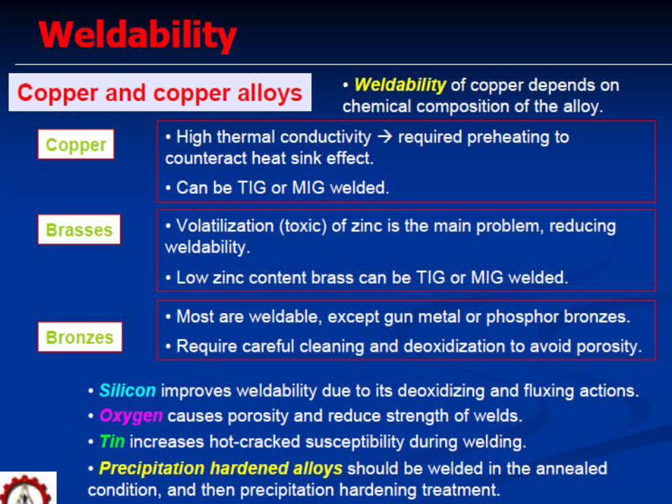
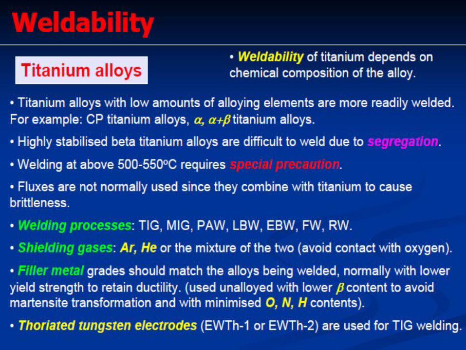
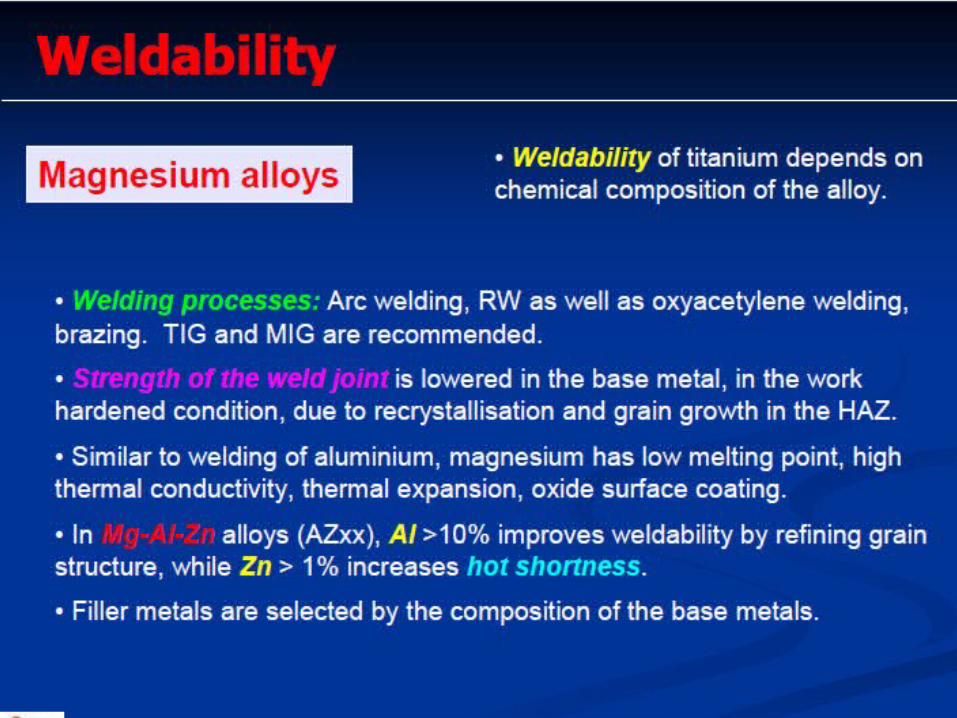
heating weldability of low alloy steels3. Welding of stainless steels. 4. Schaffler and Delong diagrams; 5. welding of cast irons, Cu; Al; Ti and Ni
alloys. 6. Processes- difficulties; 7. Microstructures; defects and remedial
measures.
Learning Activities1. Look up
Keywords2. View Slides; 3. Read Notes, 4. Listen to lecture
Keywords:
CCT Diagram for Weld
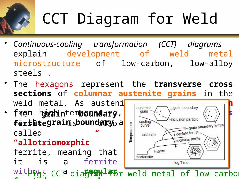
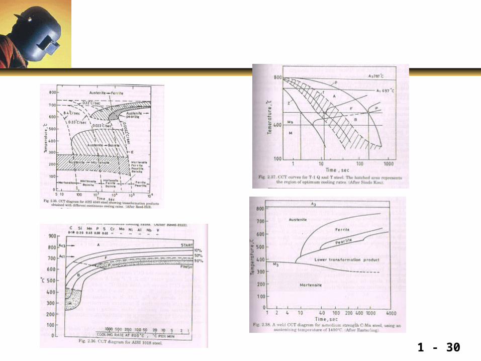
• Continuous-cooling transformation (CCT) diagrams explain development of weld metal microstructure of low-carbon, low-alloy steels .
• The hexagons represent the transverse cross sections of columnar austenite grains in the weld metal. As austenite (g) is cooled down from high temperature, ferrite (a) nucleates at the grain boundary and grows inward.
• The grain boundary ferrite is also called “allotriomorphic” ferrite, meaning that it is a ferrite without a regular faceted shape reflecting its internal crystalline structure.
Fig: CCT diagram for weld metal of low carbon steel
CCT Diagram for Weld continued…
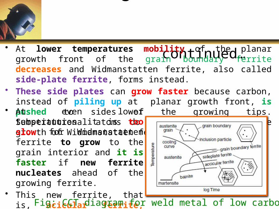
• At lower temperatures mobility of the planar growth front of the grain boundary ferrite decreases and Widmanstatten ferrite, also called side-plate ferrite, forms instead.
• These side plates can grow faster because carbon, instead of piling up at planar growth front, is pushed to sides of the growing tips. Substitutional atoms do not diffuse during the growth of Widmanstatten ferrite.
• At even lower temperatures it is too slow for Widmanstatten ferrite to grow to the grain interior and it is faster if new ferrite nucleates ahead of the growing ferrite.
• This new ferrite, that is, acicular ferrite, nucleates at inclusion particles and has randomly oriented short ferrite needles with a basket weave feature. Fig: CCT diagram for weld metal of low carbon steel
Microstructure of Weld Metal
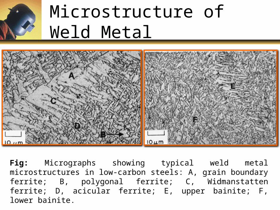
Fig: Micrographs showing typical weld metal microstructures in low-carbon steels: A, grain boundary ferrite; B, polygonal ferrite; C, Widmanstatten ferrite; D, acicular ferrite; E, upper bainite; F, lower bainite.
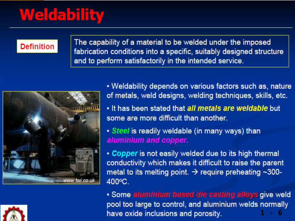
Weldability
1 - 6
1 - 7
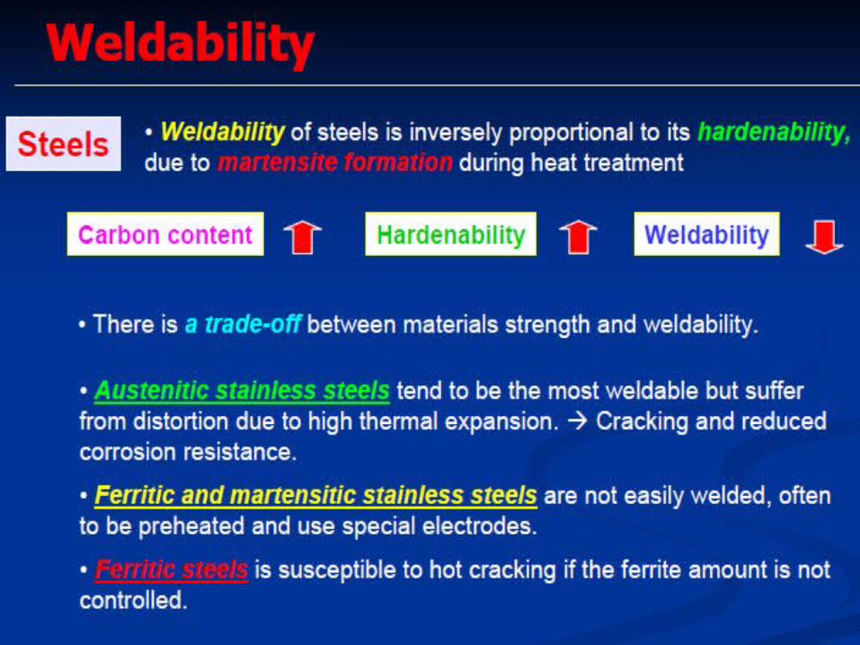
Weldability of steel
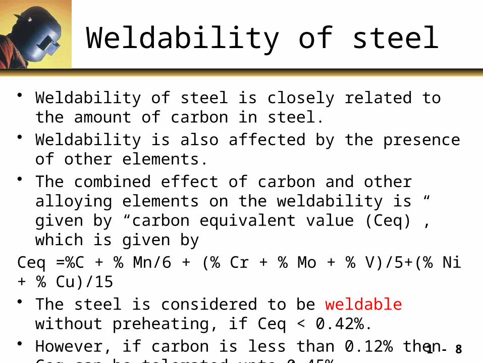
• Weldability of steel is closely related to the amount of carbon in steel.
• Weldability is also affected by the presence of other elements. • The combined effect of carbon and other alloying elements on the
weldability is given by “carbon equivalent value (Ceq)”, which is given by
Ceq =%C + % Mn/6 + (% Cr + % Mo + % V)/5+(% Ni + % Cu)/15• The steel is considered to be weldable without preheating, if Ceq
< 0.42%.• However, if carbon is less than 0.12% then Ceq can be tolerated
upto 0.45%.
1 - 8
Schaeffler Diagram
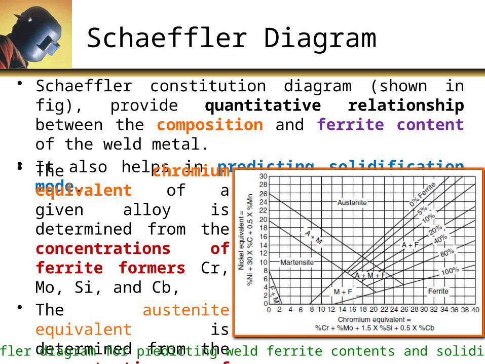
• Schaeffler constitution diagram (shown in fig), provide quantitative relationship between the composition and ferrite content of the weld metal.
• It also helps in predicting solidification mode.• The chromium equivalent of
a given alloy is determined from the concentrations of ferrite formers Cr, Mo, Si, and Cb,
• The austenite equivalent is determined from the concentrations of austenite formers Ni, C, and Mn.
Fig: Schaeffler diagram for predicting weld ferrite contents and solidification mode
DeLong’s Diagram
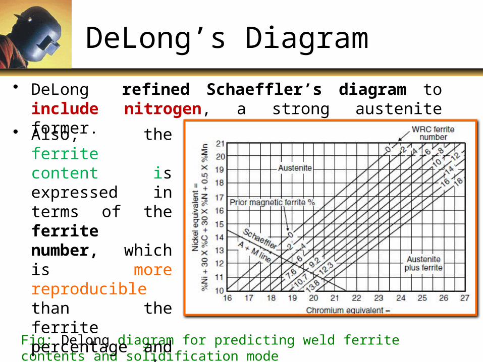
• DeLong refined Schaeffler’s diagram to include nitrogen, a strong austenite former.
Fig: Delong diagram for predicting weld ferrite contents and solidification mode
• Also, the ferrite content is expressed in terms of the ferrite number, which is more reproducible than the ferrite percentage and can be determined nondestructively by magnetic means.
1 - 11
1 - 12
1 - 13
1 - 14
1 - 15
1 - 16
1 - 17
1 - 18
1 - 19

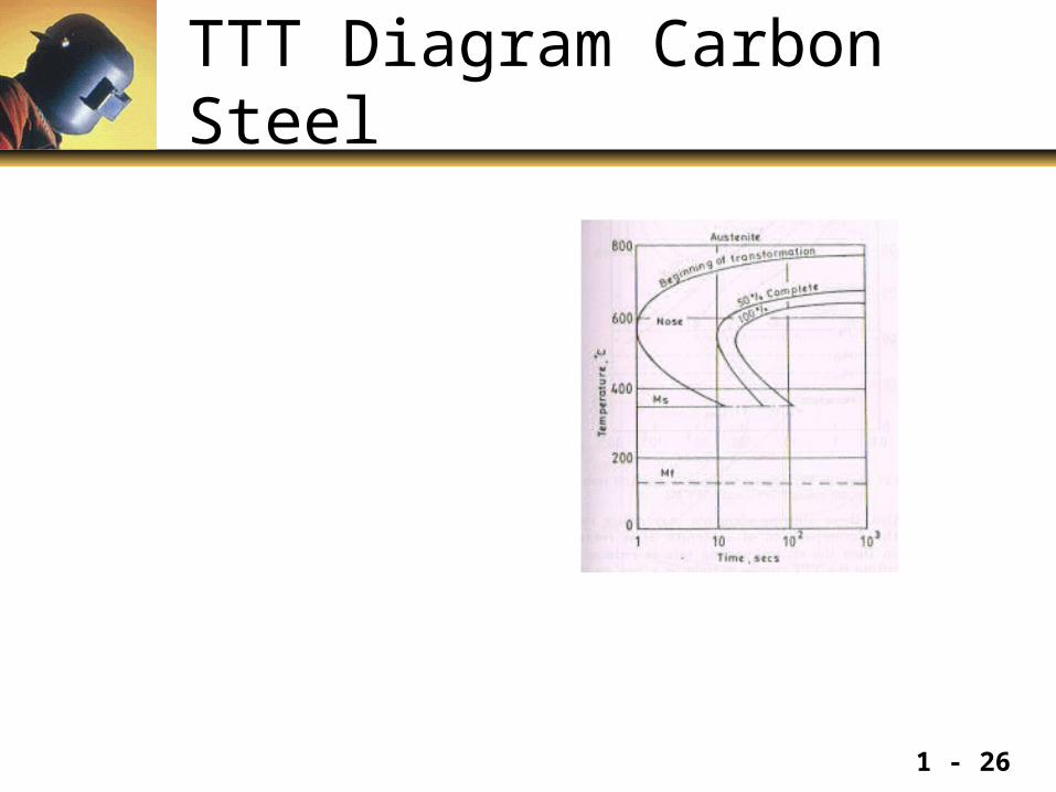
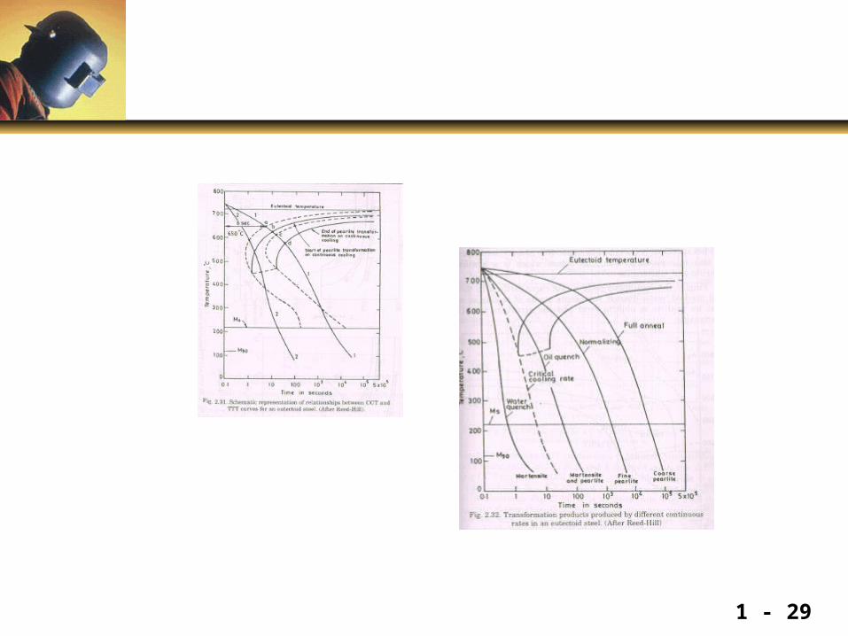
TTT Diagram Carbon Steel
1 - 26
1 - 27
1 - 28
1 - 29
1 - 30