U5 p1 ntm processes
32
Manufacturing Technology II (ME-202) Nontraditional Manufacturing Processes Dr. Chaitanya Sharma PhD. IIT Roorkee
-
Upload
gautam-buddha-university-school-of-management -
Category
Education
-
view
197 -
download
0
Transcript of U5 p1 ntm processes
Manufacturing Technology II(ME-202)
Nontraditional Manufacturing
Processes
Dr. Chaitanya Sharma
PhD. IIT Roorkee

Title of slide
Lesson ObjectivesIn this chapter we shall discuss the following:
Learning Activities1. Look up
Keywords2. View Slides; 3. Read Notes, 4. Listen to
lecture
Keywords:
Nontraditional Manufacturing Processes
• Necessity to use new materials, demanding functional
requirements and miniaturization have led to evolution of
modern manufacturing processes.
• Nontraditional machining refers to a group of processes
which removes excess material without a sharp cutting tool
by various nontraditional means such as mechanical,
thermal, electrical or chemical energy (or combinations) and
developed since World War II (1940’s).
These processes do not use a sharp cutting tool in the
conventional sense.
Why We Need NTM Processes?
Nontraditional processes have been developed to meet new
and unusual machining requirements of Aerospace and
Electronics industries which are either not possible with
conventional machining or extremely costly, including the
need:
1. To machine new (harder, stronger & tougher) materials.
2. The need for unusual and/or complex geometries.
3. To achieve stringent surface (finish & texture)
requirements
Classification of Non Traditional Manufacturing
Based on the principle form of energy nontraditional manufacturingprocesses can be classified into following groups:
1. Mechanical - Erosion of work material by a high velocity stream of
abrasives and/or fluid
Example: USM, AWJM, WJM, AFM
2. Electrical - Electrochemical energy removes material
Example: ECM, ECD, ECG.
3. Thermal - Thermal energy applied to small portion of work surface,
removes material by fusion and/or vaporization
Example: EDM, WEDM, EBM, LBM, PAM, IBM
4. Chemical - chemical etchants selectively (using a mask) remove a
portion of a workpiece.
Example: Chemical milling, Blanking, Engraving and
Photochemical machining.
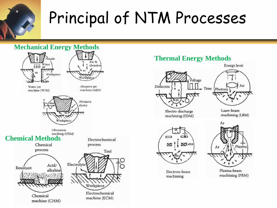
Principal of NTM Processes
Mechanical Energy Methods
Chemical Methods
Thermal Energy Methods
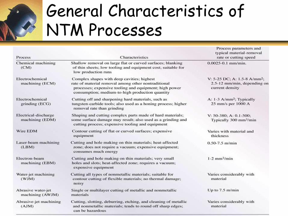
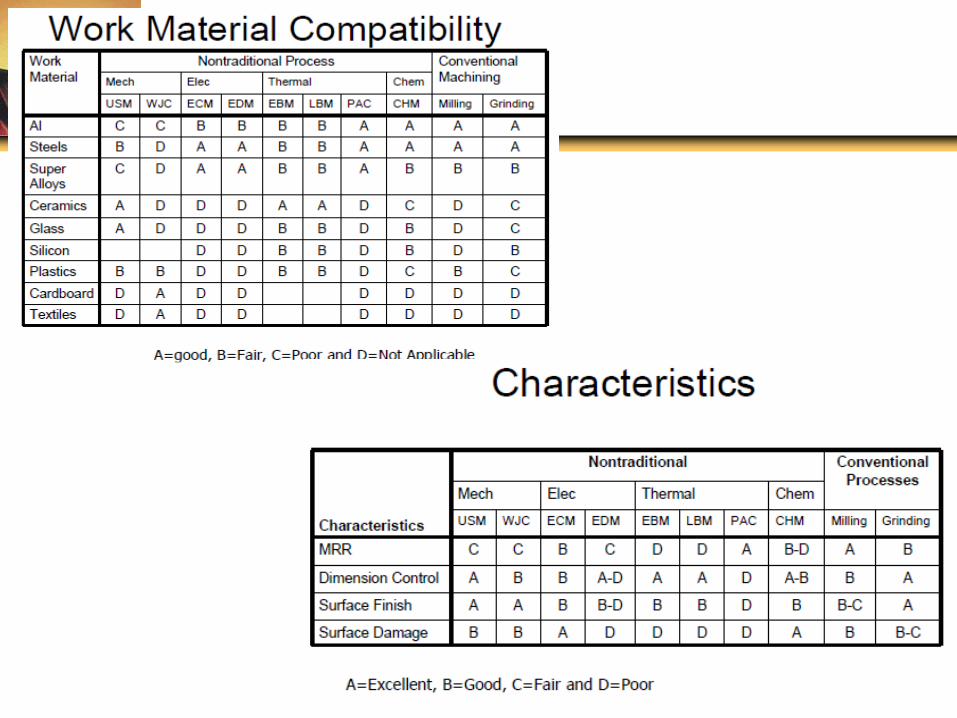
General Characteristics of NTM Processes

Surface Roughness and Tolerances in Machining
Fig: Surface roughness and tolerances obtained in various machining processes.
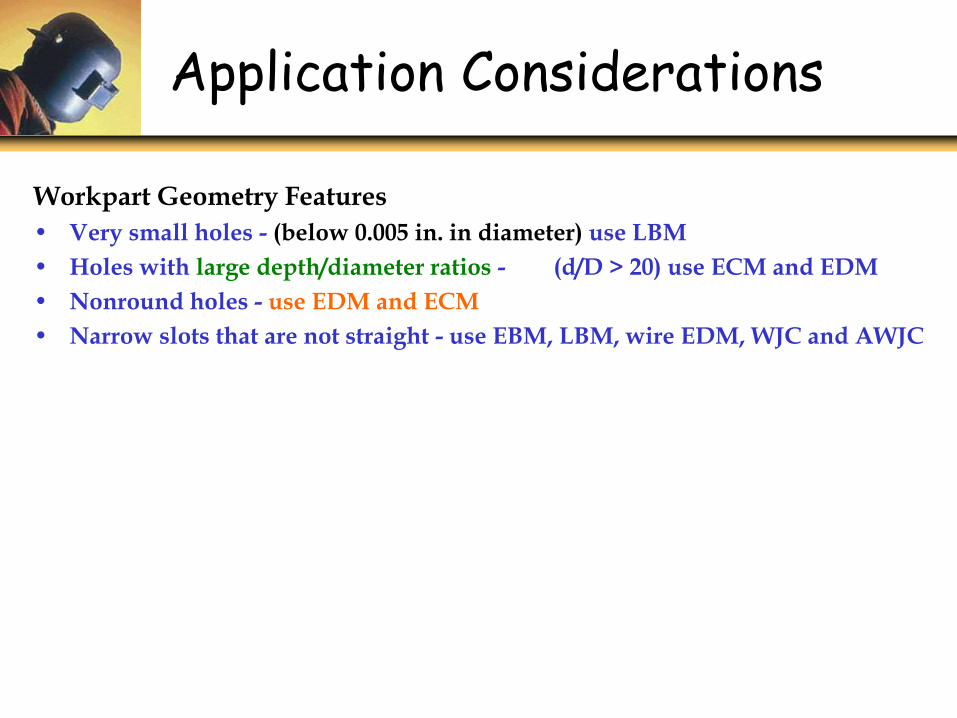
Application Considerations
Workpart Geometry Features
• Very small holes - (below 0.005 in. in diameter) use LBM
• Holes with large depth/diameter ratios - (d/D > 20) use ECM and EDM
• Nonround holes - use EDM and ECM
• Narrow slots that are not straight - use EBM, LBM, wire EDM, WJC and AWJC
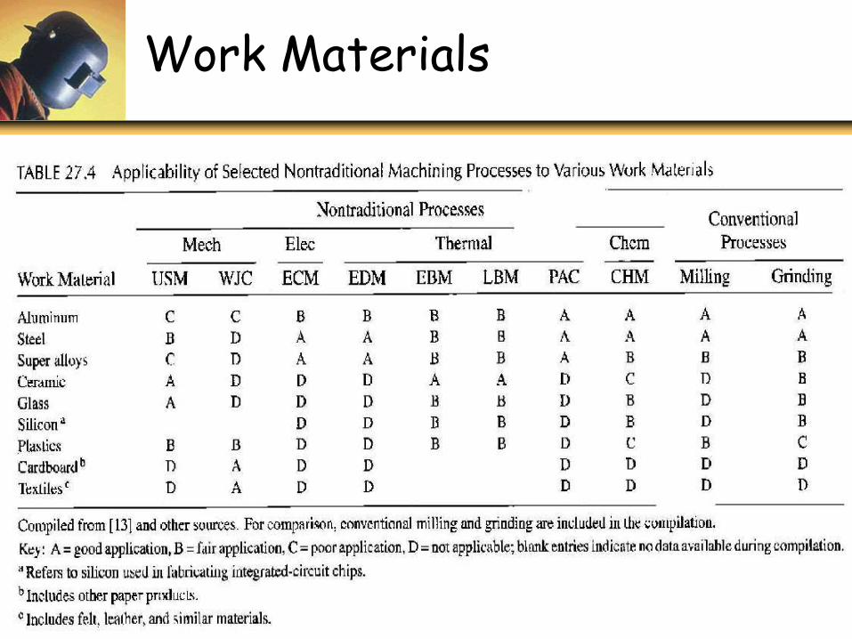
Work Materials
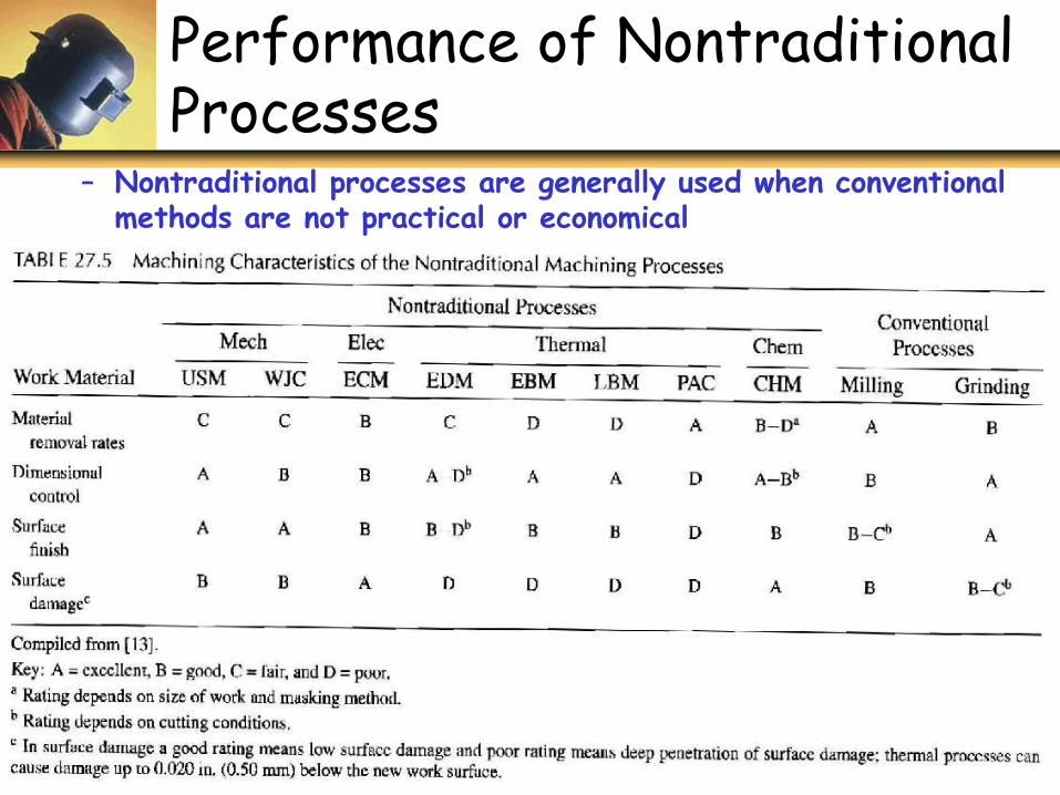
– Nontraditional processes are generally used when conventional methods are not practical or economical
Performance of Nontraditional Processes
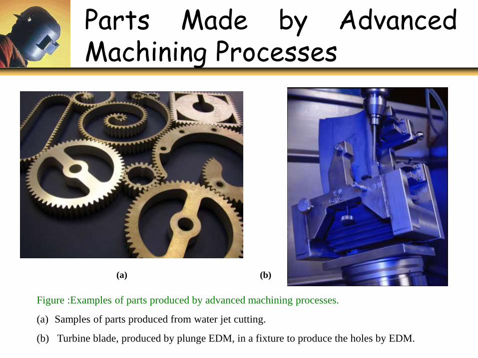
Parts Made by AdvancedMachining Processes
Figure :Examples of parts produced by advanced machining processes.
(a) Samples of parts produced from water jet cutting.
(b) Turbine blade, produced by plunge EDM, in a fixture to produce the holes by EDM.
(a) (b)
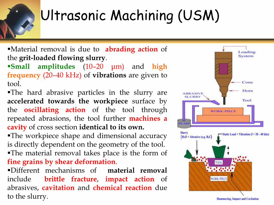
Material removal is due to abrading action ofthe grit-loaded flowing slurry.Small amplitudes (10–20 μm) and highfrequency (20–40 kHz) of vibrations are given totool.The hard abrasive particles in the slurry areaccelerated towards the workpiece surface bythe oscillating action of the tool throughrepeated abrasions, the tool further machines acavity of cross section identical to its own.The workpiece shape and dimensional accuracyis directly dependent on the geometry of the tool.The material removal takes place is the form offine grains by shear deformation.Different mechanisms of material removalinclude brittle fracture, impact action ofabrasives, cavitation and chemical reaction dueto the slurry.
Ultrasonic Machining (USM)
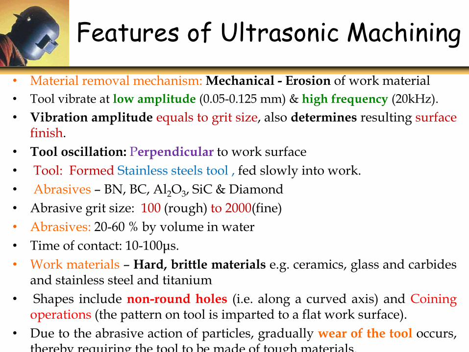
Features of Ultrasonic Machining
• Material removal mechanism: Mechanical - Erosion of work material
• Tool vibrate at low amplitude (0.05-0.125 mm) & high frequency (20kHz).
• Vibration amplitude equals to grit size, also determines resulting surfacefinish.
• Tool oscillation: Perpendicular to work surface
• Tool: Formed Stainless steels tool , fed slowly into work.
• Abrasives – BN, BC, Al2O3, SiC & Diamond
• Abrasive grit size: 100 (rough) to 2000(fine)
• Abrasives: 20-60 % by volume in water
• Time of contact: 10-100μs.
• Work materials – Hard, brittle materials e.g. ceramics, glass and carbidesand stainless steel and titanium
• Shapes include non-round holes (i.e. along a curved axis) and Coiningoperations (the pattern on tool is imparted to a flat work surface).
• Due to the abrasive action of particles, gradually wear of the tool occurs,thereby requiring the tool to be made of tough materials.
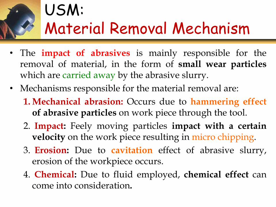
USM: Material Removal Mechanism
• The impact of abrasives is mainly responsible for theremoval of material, in the form of small wear particleswhich are carried away by the abrasive slurry.
• Mechanisms responsible for the material removal are:
1. Mechanical abrasion: Occurs due to hammering effectof abrasive particles on work piece through the tool.
2. Impact: Feely moving particles impact with a certainvelocity on the work piece resulting in micro chipping.
3. Erosion: Due to cavitation effect of abrasive slurry,erosion of the workpiece occurs.
4. Chemical: Due to fluid employed, chemical effect cancome into consideration.
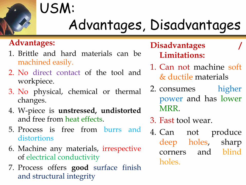
USM:Advantages, Disadvantages
Advantages:
1. Brittle and hard materials can bemachined easily.
2. No direct contact of the tool andworkpiece.
3. No physical, chemical or thermalchanges.
4. W-piece is unstressed, undistortedand free from heat effects.
5. Process is free from burrs anddistortions
6. Machine any materials, irrespectiveof electrical conductivity
7. Process offers good surface finishand structural integrity
Disadvantages /Limitations:
1. Can not machine soft& ductile materials
2. consumes higherpower and has lowerMRR.
3. Fast tool wear.
4. Can not producedeep holes, sharpcorners and blindholes.
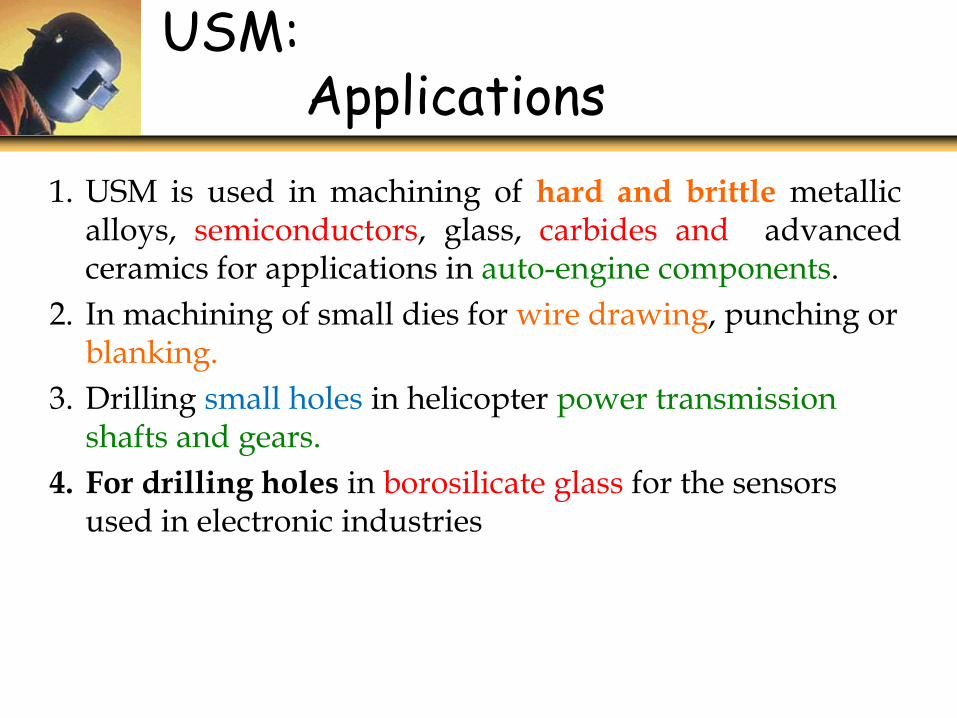
USM:Applications
1. USM is used in machining of hard and brittle metallicalloys, semiconductors, glass, carbides and advancedceramics for applications in auto-engine components.
2. In machining of small dies for wire drawing, punching or blanking.
3. Drilling small holes in helicopter power transmission shafts and gears.
4. For drilling holes in borosilicate glass for the sensors used in electronic industries
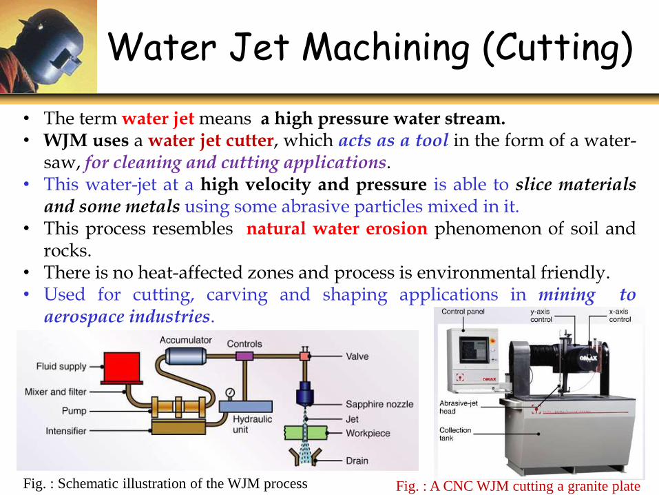
Water Jet Machining (Cutting)
Fig. : Schematic illustration of the WJM process
• The term water jet means a high pressure water stream.• WJM uses a water jet cutter, which acts as a tool in the form of a water-
saw, for cleaning and cutting applications.• This water-jet at a high velocity and pressure is able to slice materialsand some metals using some abrasive particles mixed in it.
• This process resembles natural water erosion phenomenon of soil androcks.
• There is no heat-affected zones and process is environmental friendly.• Used for cutting, carving and shaping applications in mining toaerospace industries.
Fig. : A CNC WJM cutting a granite plate
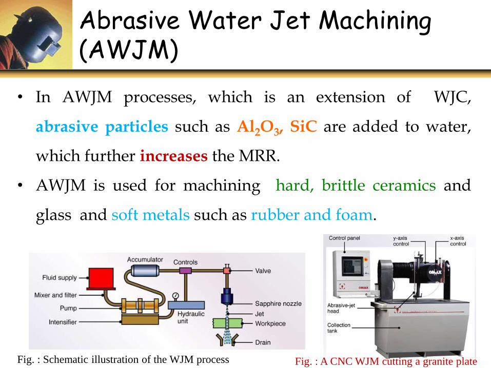
Abrasive Water Jet Machining (AWJM)
Fig. : Schematic illustration of the WJM process
• In AWJM processes, which is an extension of WJC,
abrasive particles such as Al2O3, SiC are added to water,
which further increases the MRR.
• AWJM is used for machining hard, brittle ceramics and
glass and soft metals such as rubber and foam.
Fig. : A CNC WJM cutting a granite plate
1. Water is forced at high pressure, 180-420 MPa through a small orifice
in a nozzle (0.2- 0.4 mm diameter), causing high acceleration of water.
2. Conversion of water’s potential energy into kinetic energy yields a
very high jet velocity of around 1000 m/s.
3. The impact and high pressure of the accelerating water particles
develop fine cracks on the material.
4. These fine cracks propagate further under the impact of high pressure
and abrasives to the extent that the material gets cut.
5. The extended version of WJM is AWJM. In AWJM process the particles
of abrasives such as sand (SiO2) or beads of glass are added in the
water jet in-order to enhance its ability of cutting by many folds.
Principle of WJM & AWJM
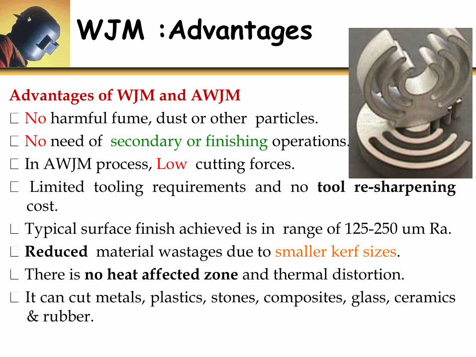
WJM :Advantages
Advantages of WJM and AWJM
No harmful fume, dust or other particles.
No need of secondary or finishing operations.
In AWJM process, Low cutting forces.
Limited tooling requirements and no tool re-sharpeningcost.
Typical surface finish achieved is in range of 125-250 um Ra.
Reduced material wastages due to smaller kerf sizes.
There is no heat affected zone and thermal distortion.
It can cut metals, plastics, stones, composites, glass, ceramics& rubber.
WJM: Disadvantages
Disadvantages of WJM and AWJM
Cannot cut materials which degrades quickly withmoisture.
Higher cutting speeds (used for rough cutting)degradethe surface finish.
Greater chance of cracking in brittle materials.
With WJM process, thick parts cannot be cut accuratelyand economically.
The equipment used are quite expensive.
There are safety concerns due to noise and highpressures.
WJM: Applications
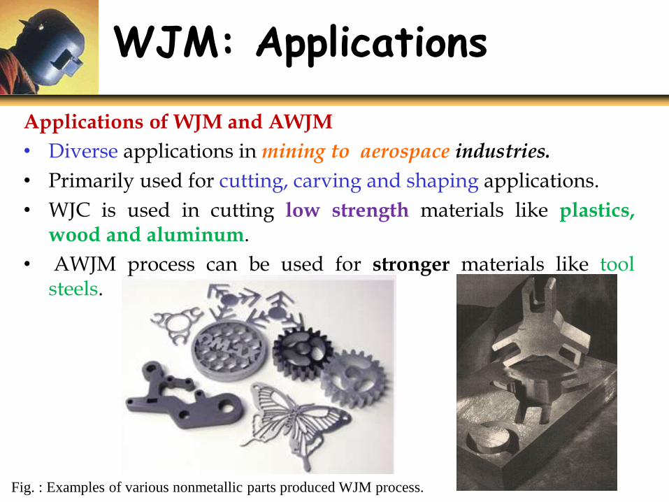
Fig. : Examples of various nonmetallic parts produced WJM process.
Applications of WJM and AWJM
• Diverse applications inmining to aerospace industries.
• Primarily used for cutting, carving and shaping applications.
• WJC is used in cutting low strength materials like plastics,wood and aluminum.
• AWJM process can be used for stronger materials like toolsteels.
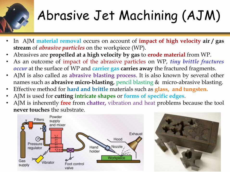
• In AJM material removal occurs on account of impact of high velocity air / gasstream of abrasive particles on the workpiece (WP).
• Abrasives are propelled at a high velocity by gas to erode material from WP.• As an outcome of impact of the abrasive particles on WP, tiny brittle fracturesoccur at the surface of WP and carrier gas carries away the fractured fragments.
• AJM is also called as abrasive blasting process. It is also known by several othernames such as abrasive micro-blasting, pencil blasting & micro-abrasive blasting.
• Effective method for hard and brittle materials such as glass, and tungsten.• AJM is used for cutting intricate shapes or forms of specific edges.• AJM is inherently free from chatter, vibration and heat problems because the tool
never touches the substrate.
Abrasive Jet Machining (AJM)
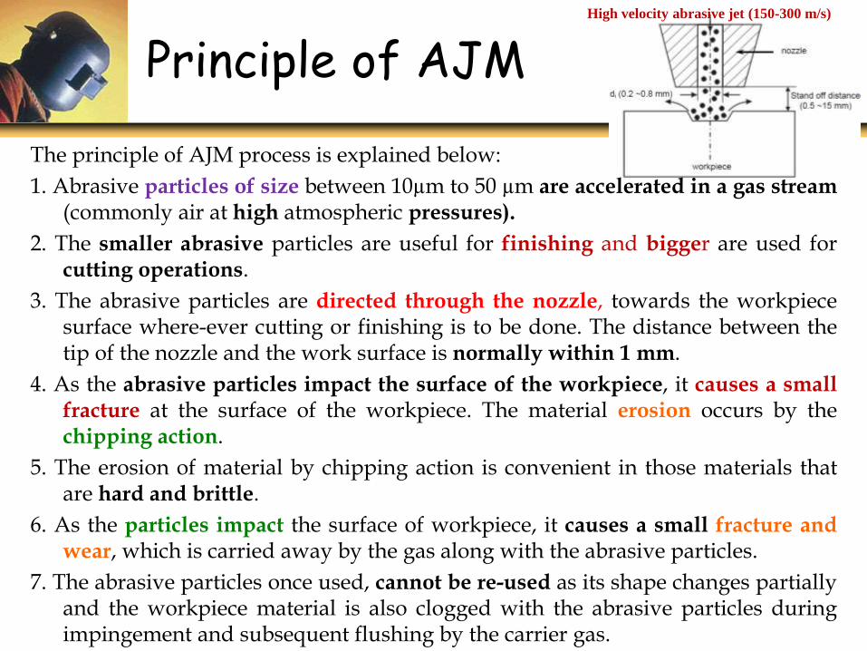
Principle of AJMHigh velocity abrasive jet (150-300 m/s)
The principle of AJM process is explained below:
1. Abrasive particles of size between 10µm to 50 µm are accelerated in a gas stream(commonly air at high atmospheric pressures).
2. The smaller abrasive particles are useful for finishing and bigger are used forcutting operations.
3. The abrasive particles are directed through the nozzle, towards the workpiecesurface where-ever cutting or finishing is to be done. The distance between thetip of the nozzle and the work surface is normally within 1 mm.
4. As the abrasive particles impact the surface of the workpiece, it causes a smallfracture at the surface of the workpiece. The material erosion occurs by thechipping action.
5. The erosion of material by chipping action is convenient in those materials thatare hard and brittle.
6. As the particles impact the surface of workpiece, it causes a small fracture andwear, which is carried away by the gas along with the abrasive particles.
7. The abrasive particles once used, cannot be re-used as its shape changes partiallyand the workpiece material is also clogged with the abrasive particles duringimpingement and subsequent flushing by the carrier gas.
Advantages of AJM:
o For machining fragile, brittle and heat sensitive materials
o Localized forces and less heat generation than theconventional machining processes.
o No tool-workpiece contact, hence lesser force and heatgeneration.
o There is no damage to the workpiece surface.
o High flexibility.
o Low power consumption.
AJM: Advantages
Disadvantages of AJM:
The process is limited to brittle and hard materials
High nozzle wear rate
Low MRR
The process results in poor machining accuracy
The process can cause environmental pollution
AJM: Disadvantages
Metal working: De-burring of some critical zones in themachined parts.
Drilling and cutting of the thin and hardened metal sections.
Removing the machining marks, flaws, chrome and anodizingmarks.
Glass: Cutting of the optical fibers without altering itswavelength
Cutting of extremely thin sections of glass and intricate curvedpatterns
Cutting, drilling and frosting precision optical lenses.
Cleaning and dressing the grinding wheels used for glass.
Grinding: Cleaning residues from diamond wheels, dressingwheels of any shape & size.
AJM Applications
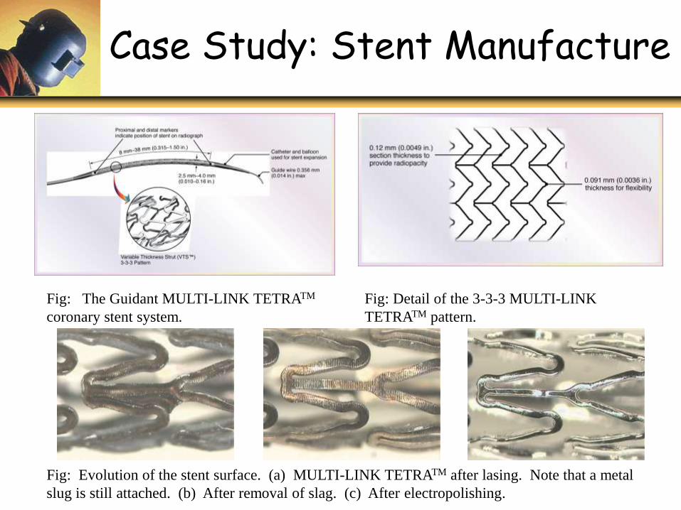
Case Study: Stent Manufacture
Fig: The Guidant MULTI-LINK TETRATM
coronary stent system.
Fig: Detail of the 3-3-3 MULTI-LINK
TETRATM pattern.
Fig: Evolution of the stent surface. (a) MULTI-LINK TETRATM after lasing. Note that a metal
slug is still attached. (b) After removal of slag. (c) After electropolishing.

The End