U2300A Series USB Modular Multifunction Data Acquisition ...
29
Find us at www.keysight.com Page 1 U2300A Series USB Modular Multifunction Data Acquisition Devices Introduction The Keysight Technologies, Inc. U2300A Series USB Modular Multifunction Data Acquisition (DAQ) devices offer a high-performance PC data-acquisition solution. The U2300A Series DAQ devices consist of two families: the basic multifunction DAQ comes in four models while the high density multifunction DAQ is made up of three models. The U2300A Series DAQ devices applications extend across industrial and education environments. Extending across industrial and education environments, the U2300A series DAQ with fast sampling rates is well suited for research and development, manufacturing as well as design validation designers. Features • Up to 3 MSa/s sampling rate for a single channel • Functions as a standalone or modular unit • Easy to use: Plug-and-play and hot swappable with Hi-Speed USB 2.0 • Up to 384 channels when incorporated into U2781A modular product chassis • Easy-to-use bundled software for quick setup and data logging to PC • 12-bit or 16-bit analog-to-digital (A/D) resolution • 24-bit programmable digital input/output • Self-calibration capability • Compatible with a wide range of Keysight Development Environments (KDEs) • USB 2.0 and USBTMC-USB488 standards • NEW! Control, automate and simplify with Keysight BenchVue software. Now included.
Transcript of U2300A Series USB Modular Multifunction Data Acquisition ...

Find us at www.keysight.com Page 1
U2300A Series USB Modular Multifunction Data Acquisition Devices
Introduction The Keysight Technologies, Inc. U2300A Series USB Modular Multifunction Data Acquisition (DAQ) devices offer a high-performance PC data-acquisition solution. The U2300A Series DAQ devices consist of two families: the basic multifunction DAQ comes in four models while the high density multifunction DAQ is made up of three models. The U2300A Series DAQ devices applications extend across industrial and education environments. Extending across industrial and education environments, the U2300A series DAQ with fast sampling rates is well suited for research and development, manufacturing as well as design validation designers.
Features • Up to 3 MSa/s sampling rate for a single channel • Functions as a standalone or modular unit • Easy to use: Plug-and-play and hot swappable with Hi-Speed USB 2.0 • Up to 384 channels when incorporated into U2781A modular product chassis • Easy-to-use bundled software for quick setup and data logging to PC • 12-bit or 16-bit analog-to-digital (A/D) resolution • 24-bit programmable digital input/output • Self-calibration capability • Compatible with a wide range of Keysight Development Environments (KDEs) • USB 2.0 and USBTMC-USB488 standards • NEW! Control, automate and simplify with Keysight BenchVue software. Now included.

Find us at www.keysight.com Page 2
High sampling rate
The U2300A Series DAQ devices can generate sampling rates of up to 3 MSa/s for a single channel. When multiple channels are configured, the device can sample data up to 1 MSa/s. The fast sampling capability allows users to perform intermittent detection easily. This is ideal when dealing with high density analog input/output signals especially when juggling between different input ranges and sampling requirements.
Flexible standalone or modular capability
The U2300A Series DAQ devices are uniquely designed with the flexibility to function as a standalone unit or as a part of a modular unit. When used together with the U2781A modular product chassis, the devices has the capability to support up to 384 channels.
Flexible system and control options with polling and continuous mode
The U2300A Series DAQ devices have two modes, polling mode and continuous mode. Selecting continuous mode enables you to acquire data continuously once the trigger signal is received.
Arbitrary waveform Designed to support arbitrary waveforms, the U2300A Series allows you to generate arbitrary waveform via SCPI commands.
Burst mode Equipped with the burst mode, the enhancement feature enables simultaneous mode for analog input acquisition. Now can you can perform sampling measurement up to the highest possible speed of the DAQ.
Trigger sources U2300A Series offers various trigger options from immediate trigger (none), analog/external digital trigger, System Synchronous Interface (SSI)/ Star trigger and Master/Slave trigger sources. These entire trigger options has the capability to configure trigger sources during A/D and digital-to-analog (D/A) operations. Selecting the slave trigger and SSI/Star trigger are recommended when the USB modules are used together with the U2781A USB modular product chassis.
Predefined function generator
Aside from supplying DC voltage, the two analog output channels are capable of generating common and predefined waveforms such as sinusoidal wave, square wave, triangle wave, sawtooth wave and noise wave.

Find us at www.keysight.com Page 3
Product Outlook and Dimensions
1 Compatib le w ith Mic rosof t Windows opera ting sys tems on ly. Requ ires a d irec t USB connection to the PC so the
appropriate driver can be instal led in the USB DAQ modu le .
Remote interface Hi-Speed USB 2.0 USBTMC-USB488 1 Power requirement +12 VDC (TYPICAL) 2 A (MAX) input rated current Power consumption +12 VDC, 550 mA maximum Operating environment Operating temperature from 0 °C to +55 °C Relative humidity at 15% to 85% RH (non-condensing) Altitude up to 2000 meters Pollution Degree 2 For indoor use only Storage compliance –20 °C to 70 °C Safety & EMC compliance Refer to Declaration of Conformity for the latest revisions of regulatory compliance at:www.keysight.com/go/conformity Shock and vibration Tested to IEC/EN 60068-2 IO connector 68-pin female VHDCI Type Dimension (W × D × H) Module dimension: 120.00 mm × 182.40 mm × 44.00 mm (with plastic casing) 105.00 mm × 174.54 mm × 25.00 mm (without plastic casing) Terminal block dimension: 103.00 mm × 85.20 mm × 42.96 mm Weight 565 g (with plastic casing) 400 g (without plastic casing)
Front view
Rear view
44.00 mm
182.40 m
m
120.00 mm
Product characteristics and general specifications
Find us at www.keysight.com Page 4
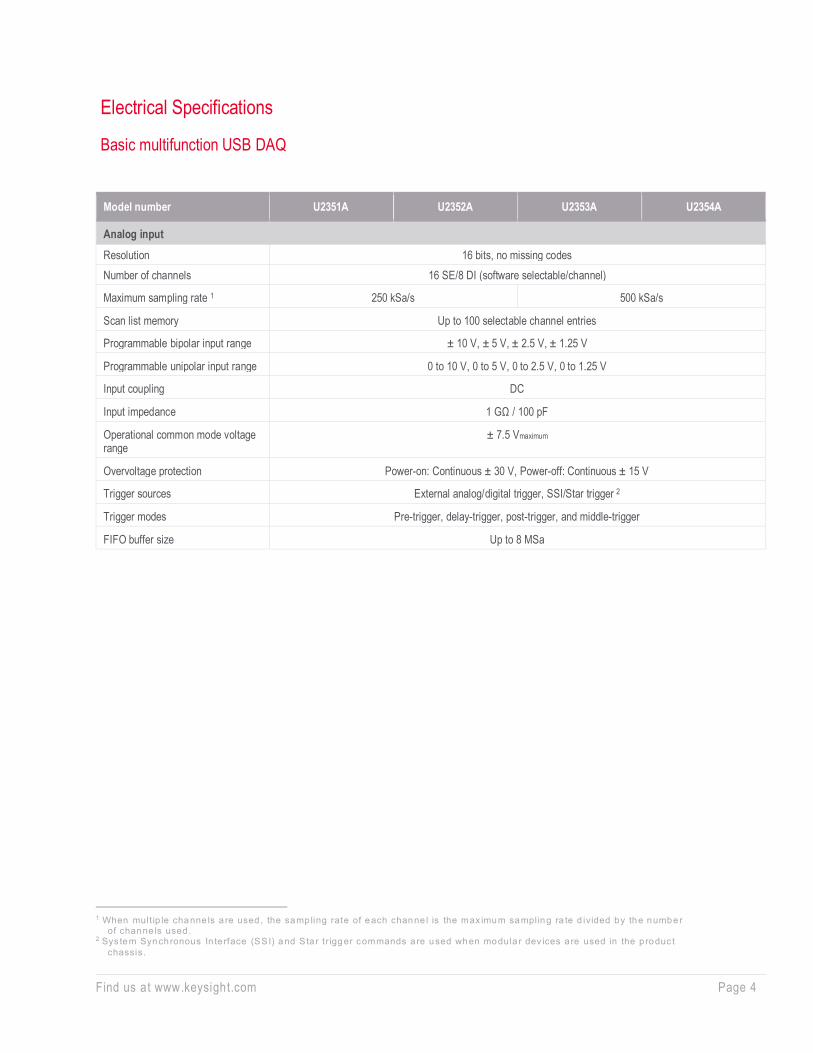
Electrical Specifications
Basic multifunction USB DAQ
1 When mult ip le channe ls a re used , the samp ling rate of each channe l is the max imum sampling ra te d ivided by the number
of channe ls used . 2 Sys tem Synchronous In te rface (SSI) and S ta r tr igger commands a re used when modula r dev ices a re used in the p roduc t
chassis.
Model number U2351A U2352A U2353A U2354A
Analog input Resolution 16 bits, no missing codes Number of channels 16 SE/8 DI (software selectable/channel)
Maximum sampling rate 1 250 kSa/s 500 kSa/s
Scan list memory Up to 100 selectable channel entries
Programmable bipolar input range ± 10 V, ± 5 V, ± 2.5 V, ± 1.25 V
Programmable unipolar input range 0 to 10 V, 0 to 5 V, 0 to 2.5 V, 0 to 1.25 V
Input coupling DC
Input impedance 1 GΩ / 100 pF
Operational common mode voltage range
± 7.5 Vmaximum
Overvoltage protection Power-on: Continuous ± 30 V, Power-off: Continuous ± 15 V
Trigger sources External analog/digital trigger, SSI/Star trigger 2
Trigger modes Pre-trigger, delay-trigger, post-trigger, and middle-trigger
FIFO buffer size Up to 8 MSa

Find us at www.keysight.com Page 5
1 Maximum ex te rna l refe rence vo ltage fo r ana log ou tpu t channels (AO_EXT_REF) is ±10 V . 2 Sys tem Synchronous In te rface (SSI) and S ta r tr igger commands a re used when modula r dev ices a re used in the p roduc t
chassis.
Model number U2351A U2352A U2353A U2354A
Analog output Resolution 16 bits - 16 bits -
Number of channels 2 - 2 -
Maximum update rate 1 MSa/s - 1 MSa/s -
Output ranges 0 to 10 V, ± 10 V, 0 to AO_EXT_REF, ± AO_EXT_REF 1
- 0 to 10 V, ± 10 V, 0 to AO_EXT_REF, ± AO_EXT_REF 1
-
Output coupling DC - DC -
Output impedance 0.1 Ω typical - 0.1 Ω typical -
Stability Any passive load up to 1500 pF
- Any passive load up to 1500 pF
-
Power-on state 0 V steady state - 0 V steady state -
Trigger sources External analog/digital trigger, SSI/Star trigger 2
- External analog/digital trigger, SSI/Star trigger 2
-
Trigger modes Post-trigger and delay-trigger
- Post-trigger and delay-trigger
-
FIFO buffer size One channel: Maximum 8 MSa
Two channels: Maximum 4 MSa/ch
- One channel: Maximum 8 MSa
Two channels: Maximum 4 MSa/ch
-
Function generation mode Sine, square, triangle, sawtooth, and noise
waveforms
- Sine, square, triangle, sawtooth, and noise
waveforms
-
Digital I/O
Number of channels 24-bit programmable input/output
Compatibility TTL
Input voltage VIL = 0.7 V max, IIL = 10 μA max VIH = 2.0 V min, IIH = 10 μA max
Input voltage range –0.5 V to +5.5 V
Output voltage VOL = 0.45 V max, IOL = 8 mA max VOH = 2.4 V min, IOH = 400 μA max

Find us at www.keysight.com Page 6
1 Measurement frequency’s resolu t ion :
= 12 MHz/n , n = 2 , 3 , 4, 5 , . .. , 120 M = 6 MHz, 4 MHz, 3 MHz, 2 .4 MHz, 2 .0 MHz, . .. , 0 .1 Hz (up to s ix dec ima l points)
2 20 minutes warm-up t ime is recommended .
Model number U2351A U2352A U2353A U2354A
General purpose digital counter Maximum count (2³¹–1) bits
Number of channels Two independent up/down counter
Compatibility TTL
Clock source Internal or external
Base clock available 48 MHz
Maximum clock source frequency 12 MHz
Input frequency range 1 0.1 Hz to 6 MHz at 50% duty cycle
Pulse width measurement range 0.167 μs to 178.956 s
Analog trigger
Trigger source All analog input channels, External analog trigger (EXTA_TRIG)
Trigger level ± Full scale for internal; ± 10 V for external
Trigger conditions Above high, below low, and window (software selectable)
Trigger level resolution 8 bits
Bandwidth 400 kHz
Input impedance for EXTA_TRIG 20 kΩ
Coupling DC
Overvoltage protection Continuous for ± 35 Vmaximum
Digital trigger
Compatibility TTL/CMOS
Response Rising or falling edge
Pulse width 20 ns minimum
Calibration 2
On board reference voltage 5 V
Temperature drift ± 2 ppm/°C
Stability ± 6 ppm/1000 hrs
General
Remote interface Hi-Speed USB 2.0
Device class USBTMC-USB488
Programmable interface Standard Commands for Programmable Instruments (SCPI) and IVI-COM

Find us at www.keysight.com Page 7
High density multifunction USB DAQ
1 When mult ip le channe ls a re used in the U2355A o r U2356A, the samp ling ra te of each channe l is the max imum samp ling
ra te d iv ided by the number of channe ls used . Fo r mult ip le channe ls used in the U2331A, the samp ling ra te of each channe l = (1 MSa/s ) / number of channe ls used.
2 Sys tem Synchronous In te rface (SSI) and S ta r tr igger commands a re used when modula r dev ices a re used in the p roduc t chassis.
3 Maximum ex te rna l refe rence vo ltage fo r ana log ou tpu t channels (AO_EXT_REF) is ± 10 V .
Model number U2355A U2356A U2331A
Analog input Resolution 16 bits, no missing codes 12 bits, no missing codes
Number of channels 64 SE/32 DI (software selectable/channel)
Maximum sampling rate 1 250 kSa/s 500 kSa/s 3 MSa/s (single channel) 1 MSa/s (multiple channels)
Scan list memory Up to 100 selectable channel entries
Programmable bipolar input range ± 10 V, ± 5 V, ± 2.5 V, ± 1.25 V ± 10 V, ± 5 V, ± 2.5 V, ± 1.25 V, ± 1 V, ± 0.5 V,
± 0.25 V, ± 0.2 V, ± 0.05 V
Programmable unipolar input range 0 to 10 V, 0 to 5 V, 0 to 2.5 V, 0 to 1.25 V 0 to 10 V, 0 to 5 V, 0 to 4 V, 0 to 2.5 V, 0 to 2 V, 0 to 1 V, 0 to 0.5 V, 0 to 0.4 V, 0 to 0.1V
Input coupling DC
Input impedance 1 GΩ / 100 pF
Operational common mode voltage range ± 7.5 V maximum
Overvoltage protection Power-on: Continuous ± 30 V, Power-off: Continuous ± 15 V
Trigger sources External analog/digital trigger, SSI/Star trigger 2
Trigger modes Pre-trigger, delay-trigger, post-trigger, and middle-trigger
FIFO buffer size Up to 8 MSa
Analog output
Resolution 12 bits
Number of channels 2
Maximum update rate 1 MSa/s
Output ranges 0 to 10 V, ± 10 V, 0 to AO_EXT_REF, ± AO_EXT_REF 3
Output coupling DC
Output impedance 0.1 Ω Typical
Stability Any passive load up to 1500 pF
Power-on state 0 V steady state
Trigger sources External analog/digital trigger, SSI/Star trigger 2
Trigger modes Post-trigger and delay-trigger
FIFO buffer size One channel: Maximum 8 MSa Two channels: Maximum 4 MSa/ch
Function generation mode Sine, square, triangle, sawtooth, and noise waveforms

Find us at www.keysight.com Page 8
1 Measurement frequency’s resolu t ion :
= 12 MHz/n , n = 2 , 3 , 4, 5 , . .. , 120 M = 6 MHz, 4 MHz, 3 MHz, 2 .4 MHz, 2 .0 MHz, . .. , 0 .1 Hz (up to s ix dec ima l points)
Model number U2355A U2356A U2331A
Digital I/O Number of bits 24-bit programmable input/output
Compatibility TTL
Input voltage VIL = 0.7 V max, IIL = 10 μA max VIH = 2.0 V min, IIH = 10 μA max
Input voltage range –0.5 V to +5.5 V
Output voltage VOL = 0.45 V max, IOL = 8 mA max VOH = 2.4 V min, IOH = 400 μA max
General purpose digital counter
Maximum count (2³¹ – 1) bits
Number of channels Two independent up/down counter
Compatibility TTL
Clock source Internal or external
Base clock available 48 MHz
Maximum clock source frequency 12 MHz
Input frequency range 1 0.1 Hz to 6 MHz at 50% duty cycle
Pulse width measurement range 0.167 μs to 178.956 s
Analog trigger
Trigger source All analog input channels, External analog trigger (EXTA_TRIG)
Trigger level ± Full scale for internal; ± 10 V for external
Trigger conditions Above high, below low, and window (software selectable)
Trigger level resolution 8 bits
Bandwidth 400 kHz
Input impedance for EXTA_TRIG 20 kΩ
Coupling DC
Overvoltage protection Continuous for ± 35 Vmaximum
Digital trigger
Compatibility TTL/CMOS
Response Rising or falling edge
Pulse width 20 ns minimum

Find us at www.keysight.com Page 9
1 20 minutes warm-up t ime is recommended .
Model number U2355A U2356A U2331A
Calibration 1 On board reference 24-bit programmable input/output
Temperature drift TTL
Stability ± 6 ppm/1000 hrs
General
Remote interface Hi-Speed USB 2.0
Device class USBTMC-USB488
Programmable interface Standard Commands for Programmable Instruments (SCPI) and IVI-COM
Find us at www.keysight.com Page 10
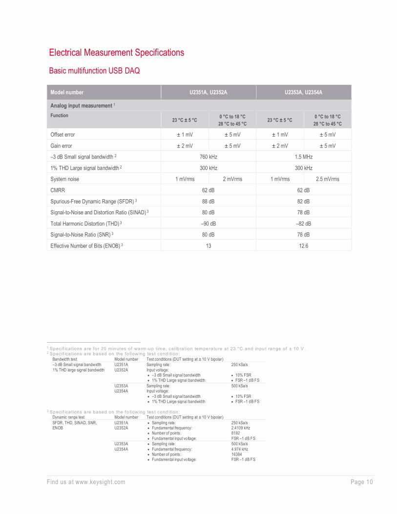
Electrical Measurement Specifications
Basic multifunction USB DAQ
1 Specif ica t ions a re fo r 20 minutes of warm-up t ime, cal ib ra t ion tempera tu re a t 23 °C and inpu t range of ± 10 V . 2 Specif ica t ions a re based on the fo llow ing tes t cond ition :
Bandwidth test Model number Test conditions (DUT setting at ± 10 V bipolar) –3 dB Small signal bandwidth 1% THD large signal bandwidth
U2351A U2352A
Sampling rate: Input voltage: • –3 dB Small signal bandwidth • 1% THD Large signal bandwidth
250 kSa/s • 10% FSR • FSR –1 dB FS
U2353A U2354A
Sampling rate: Input voltage: • –3 dB Small signal bandwidth • 1% THD Large signal bandwidth
500 kSa/s • 10% FSR • FSR –1 dB FS
3 Specif ica t ions a re based on the fo llow ing tes t cond ition :
Dynamic range test Model number Test conditions (DUT setting at ± 10 V bipolar) SFDR, THD, SINAD, SNR, ENOB
U2351A U2352A
• Sampling rate: • Fundamental frequency: • Number of points: • Fundamental input voltage:
250 kSa/s 2.4109 kHz 8192 FSR –1 dB FS
U2353A U2354A
• Sampling rate: • Fundamental frequency: • Number of points: • Fundamental input voltage:
500 kSa/s 4.974 kHz 16384 FSR –1 dB FS
Model number U2351A, U2352A U2353A, U2354A
Analog input measurement 1 Function
23 °C ± 5 °C 0 °C to 18 °C 28 °C to 45 °C
23 °C ± 5 °C 0 °C to 18 °C 28 °C to 45 °C
Offset error ± 1 mV ± 5 mV ± 1 mV ± 5 mV
Gain error ± 2 mV ± 5 mV ± 2 mV ± 5 mV
–3 dB Small signal bandwidth 2 760 kHz 1.5 MHz
1% THD Large signal bandwidth 2 300 kHz 300 kHz
System noise 1 mVrms 2 mVrms 1 mVrms 2.5 mVrms
CMRR 62 dB 62 dB
Spurious-Free Dynamic Range (SFDR) 3 88 dB 82 dB
Signal-to-Noise and Distortion Ratio (SINAD) 3 80 dB 78 dB
Total Harmonic Distortion (THD) 3 –90 dB –82 dB
Signal-to-Noise Ratio (SNR) 3 80 dB 78 dB
Effective Number of Bits (ENOB) 3 13 12.6

Find us at www.keysight.com Page 11
1 Specif ica t ions a re fo r 20 minutes of warm-up t ime, cal ib ra t ion tempera tu re a t 23 °C and inpu t range of ± 10 V .
Model number U2351A, U2353A
Analog input measurement 1
Function 23 °C ± 5 °C 0 °C to 18 °C 28 °C to 45 °C
Offset error ± 1 mV ± 4mV
Gain error ± 4mV ± 5 mV
Slew rate 19 V/μs
Rise time 0.9 μs
Fall time 0.9 μs
Settling time to 1% output error 4 μs
Driving capability 5 mA
Glitch energy 5 ns-V (typical), 80 ns-V (maximum)

Find us at www.keysight.com Page 12
High density multifunction USB DAQ
1 Specif ica t ions a re fo r 20 minutes of warm-up t ime, cal ib ra t ion tempera tu re a t 23 °C and inpu t range of ± 10 V . 2 Specif ica t ions a re based on the fo llow ing tes t cond ition :
Bandwidth test Model number Test conditions (DUT setting at ± 10 V bipolar) –3 dB Small signal bandwidth 1% THD large signal bandwidth
U2351A U2352A
Sampling rate: Input voltage: • –3 dB Small signal bandwidth • 1% THD Large signal bandwidth
250 kSa/s • 10% FSR • FSR –1 dB FS
U2353A U2354A
Sampling rate: Input voltage: • –3 dB Small signal bandwidth • 1% THD Large signal bandwidth
500 kSa/s • 10% FSR • FSR –1 dB FS
3 Specif ica t ions a re based on the fo llow ing tes t cond ition :
Dynamic range test Model number Test conditions (DUT setting at ± 10 V bipolar) SFDR, THD, SINAD, SNR, ENOB
U2351A U2352A
• Sampling rate: • Fundamental frequency: • Number of points: • Fundamental input voltage:
250 kSa/s 2.4109 kHz 8192 FSR –1 dB FS
U2353A U2354A
• Sampling rate: • Fundamental frequency: • Number of points: • Fundamental input voltage:
500 kSa/s 4.974 kHz 16384 FSR –1 dB FS
Model number U2355A U2356A U2331A
Analog input measurement 1
Function 23 °C ± 5 °C 0 °C to 18 °C 28 °C to 45 °C
23 °C ± 5 °C 0 °C to 18 °C 28 °C to 45 °C
23 °C ± 5 °C 0 °C to 18 °C 28 °C to 45 °C
Offset error ± 1 mV ± 2 mV ± 1 mV ± 2 mV ± 2 mV ± 3 mV
Gain error ± 2 mV ± 3 mV ± 2 mV ± 6 mV ± 6 mV ± 7.5 mV
–3 dB small signal bandwidth 2
760 kHz 1.3 MHz 1.2 MHz
1% THD large signal bandwidth 2 400 kHz 400 kHz N/A
System noise 1 mVrms 2 mVrms 1 mVrms 4 mVrms 3 mVrms 5 mVrms
CMRR 64 dB 61 dB 62 dB
Spurious-Free Dynamic Range (SFDR) 3
88 dB 86 dB 71 dB
Signal-to-Noise and Distortion Ratio (SINAD) 3
80 dB 78 dB 72 dB
Total Harmonic Distortion (THD) 3 –90 dB –84 dB –76 dB
Signal-to-Noise Ratio (SNR) 3 80 dB 78 dB 72 dB
Effective Number of Bits (ENOB) 3 13 12.6 11.6

Find us at www.keysight.com Page 13
1 Specif ica t ions a re fo r 20 minutes of warm-up t ime, cal ib ra t ion tempera tu re a t 23 °C and inpu t range of ± 10 V .
Model number U2355A, U2356A U2331A
Analog input measurement 1 Function 23 °C ± 5 °C 0 °C to 18 °C
28 °C to 45 °C 23 °C ± 5 °C 0 °C to 18 °C
28 °C to 45 °C
Offset error ± 1 mV ± 4 mV ± 1.5 mV ± 4 mV
Gain error ± 4 mV ± 5 mV ± 4 mV ± 5 mV
Slew rate 19 V/μs 19 V/μs
Rise time 0.9 μs 0.9 μs
Fall time 0.9 μs 0.9 μs
Settling time to 1% output error 4 μs 4 μs
Driving capability 5 mA 5 mA
Glitch energy 5 ns-V (typical), 80 ns-V (maximum) 5 ns-V (typical), 80 ns-V (maximum)

Find us at www.keysight.com Page 14
DC Characteristics
Accuracy specifications
1 Offse t e rro r is measured a t midsca le of ful l range. 2 Accuracy = ± [% of | (Ga in e rro r / (Measured value – Midsca le of FSR))| + Offse t e rror]
Model number U2351A, U2352A, U2353A, U2354A
Analog input
Unipolar range (V) Offset error (mV) 1 Gain error (mV) Accuracy (% of reading + offset error) 2
10 1.5 2.0 0.04% + 1.5 mV
5 1.5 2.0 0.08% + 1.5 mV
2.5 1.0 1.0 0.08% + 1.0 mV
1.25 1.0 1.0 0.16% + 1.0 mV
Bipolar range (V) Offset error (mV) 1 Gain error (mV) Accuracy (% of reading + offset error) 2
10 1.0 2.0 0.02% + 1.0 mV
5 1.0 2.0 0.04% + 1.0 mV
2.5 1.0 1.5 0.06% + 1.0 mV
1.25 1.0 1.5 0.12% + 1.0 mV
Model number U2355A, U2356A
Unipolar range (V) Offset error (mV) 1 Gain error (mV) Accuracy (% of reading + offset error) 2
10 1.0 1.5 0.03% + 1.0 mV
5 1.0 1.5 0.06% + 1.0 mV
2.5 1.0 1.0 0.08% + 1.0 mV
1.25 1.0 1.0 0.16% + 1.0 mV
Bipolar range (V) Offset error (mV) 1 Gain error (mV) Accuracy (% of reading + offset error) 2
10 1.0 2.0 0.02% + 1.0 mV
5 1.0 2.0 0.04% + 1.0 mV
2.5 1.0 1.5 0.06% + 1.0 mV
1.25 1.0 1.5 0.12% + 1.0 mV

Find us at www.keysight.com Page 15
• The above specifications are typical for 23 °C • Specifications are for 20 minutes warm-up and self-calibration • The measurement are calculated with 100 points averaging of data
1 Offse t e rro r is measured a t midsca le of ful l range. 2 Accuracy = ± [% of | (Ga in e rro r / (Measured value – Midsca le of FSR))| + Offse t e rror]
Model number U2331A
Analog input
Unipolar range (V) Offset error (mV) 1 Gain error (mV) Accuracy (% of reading + offset error) 2
10 1.5 4.0 0.08% + 1.5 mV
5 1.5 2.0 0.08% + 1.5 mV
4 1.5 2.0 0.10% + 1.5 mV
2.5 1.0 1.5 0.12% + 1.0 mV
2 1.0 1.0 0.10% + 1.0 mV
1 1.0 1.0 0.20% + 1.0 mV
0.5 1.0 1.0 0.41% + 1.0 mV
0.4 1.0 1.0 0.51% + 1.0 mV
0.1 1.0 1.0 2.04% + 1.0 mV
Bipolar range (V) Offset error (mV) 1 Gain error (mV) Accuracy (% of reading + offset error) 2
10 2.0 6.0 0.06% + 2.0 mV
5 1.5 4.0 0.08% + 1.5 mV
2.5 1.5 2.0 0.08% + 1.5 mV
1.25 1.0 1.5 0.12% + 1.0 mV
1 1.0 1.0 0.10% + 1.0 mV
0.5 1.0 1.0 0.20% + 1.0 mV
0.25 1.0 1.0 0.40% + 1.0 mV
0.2 1.0 1.0 0.50% + 1.0 mV
0.05 1.0 1.0 2.02% + 1.0 mV

Find us at www.keysight.com Page 16
• The above specifications are typical for 23 °C • Specifications are for 20 minutes warm-up and self-calibration
1 Offse t e rro r is measured a t 0 V. 2 Accuracy = ± [% of |Ga in e rro r/Ou tput va lue| + Offse t voltage ]
Model number U2351A, U2352A, U2353A, U2354A
Analog output
Unipolar range (V) Offset error (mV) 1 Gain error (mV) Accuracy (% of reading + offset error) 2
10 1.0 2.0 0.02% + 1.0 mV
Bipolar range (V) Offset error (mV) 1 Gain error (mV) Accuracy (% of reading + offset error) 2
10 1.0 4.0 0.04% + 1.0 mV
Model number U2355A, U2356A
Unipolar range (V) Offset error (mV) 1 Gain error (mV) Accuracy (% of reading + offset error) 2
10 1.0 2.0 0.02% + 1.0 mV
Bipolar range (V) Offset error (mV) 1 Gain error (mV) Accuracy (% of reading + offset error) 2
10 1.0 4.0 0.04% + 1.0 mV
Model number U2331A
Unipolar range (V) Offset error (mV) 1 Gain error (mV) Accuracy (% of reading + offset error) 2
10 2.5 4.0 0.04% + 2.5 mV
Bipolar range (V) Offset error (mV) 1 Gain error (mV) Accuracy (% of reading + offset error) 2
10 1.5 4.0 0.04% + 1.5 mV

Find us at www.keysight.com Page 17
USB Modular DAQ App within BenchVue BenchVue software for the PC makes it simple to connect, control, capture and view multiple Keysight instruments simultaneously with no additional programming. You can derive answers faster than ever by easily viewing, logging and exporting measurement data and screen images with a few clicks from a single environment.
• Visualize multiple measurements simultaneously • Easily log data, screen shots and system state • Rapidly prototype custom test sequences • Recall past states of your USB Modular DAQ device to replicate results • Export measurement data in the desired format fast • Quickly access manuals, drivers, FAQs and videos
The USB Modular DAQ App within BenchVue allows you to quickly configure and control any of the USB DAQ devices to perform data logging and visualize measurements. With six different display options, including grids and strip charts, zooming in to details the way you want is so much easier—so you can nail that measurement error in no time. In just a few clicks, you can also record measurements and export results to popular PC-friendly applications such as Microsoft Excel and Microsoft Word for further analysis.
Get started with BenchVue, downloadable at no cost at www.keysight.com/find/benchvue.
View measurements across USB DAQ, modular and bench instruments all on one BenchVue interface.

Find us at www.keysight.com Page 18
Configure and visualize measurements flexibly and easily on BenchVue’s modern interface.

Find us at www.keysight.com Page 19
Optional Accessories: U2802A Thermocouple Input Signal Conditioner The Keysight U2802A is a 31-channel Thermocouple Input Signal Conditioner with a built-in thermistor for cold junction compensation. The U2802A converts low input voltage signals (less than ± 100 mV) from a thermocouple into an output voltage range suitable for data acquisition devices (± 10 V). The U2802A is designed for use with the U2355A/U2356A USB Modular Multifunction DAQ device for temperature measurements with thermocouples (standalone operation only). The U2802A can be attached to the DAQ device via two SCSI-II 68 conductor cables. The thermocouple complements eight standard thermocouple types which caters to a wide range of application and industrial settings.
Features to meet your demands • 31 input channels that can be independently configured to either differential thermocouple
input mode, single-ended voltage input mode, or differential voltage input mode using two input channels set to voltage input mode
• Supports the standard thermocouple types (J, K, R, S, T, N, E, and B) defined in the NIST ITS-90 Thermocouple Database
• Error detection for open thermocouple channels • Built-in isothermal construction on terminal block for improved measurement accuracy • Built-in thermistor for cold junction compensation • Built-in zeroing function to compensate for overall system offset errors due to temperature
drift and long term drift
• Up to ± 10 V input voltage range for higher voltage inputs • Sampling rate of 500 kSa/s for overall module • Sampling rate of 10 kSa/s total for all channels in thermocouple mode • Quick and easy USB setup • Robust, cost-effective, and user friendly
Applications The U2802A Thermocouple Input Signal Conditioner can be used in various applications, including:
• Product thermal analysis and characterization • Environmental chamber profiling • Process monitoring in consumer electronics markets • Material properties testing in education environments • Study of electronic temperature properties • Appliances testing

Find us at www.keysight.com Page 20
Thermocouple input mode
In thermocouple input mode, the U2802A can acquire up to ± 100 mV input signals. Each channel includes an instrumentation amplifier and a 4 Hz low-pass filter. The low-pass filter removes unwanted noise from the thermocouple wires to obtain accurate measurement data.
Voltage input mode Alternatively, you can select separate voltage input modes for each channel. The channel will be set to bypass the amplifier and filter, allowing up to ± 10V input signals to be directly routed to the DAQ device analog input. The bandwidth in this mode is more than 500 kHz.
Zero mode
In zero mode, the positive and negative inputs of the instrumentation amplifier are shorted together. The voltage measured in this mode corresponds to the offset voltage of the channel. You can subtract this offset voltage from subsequent thermocouple mode measurements to increase measurement accuracy. This mode is only applicable in thermocouple mode.
Thermocouple compatibility The U2802A is compatible with a wide range of standard thermocouple types defined in the NIST ITS-90 Thermocouple Database. This includes types J, K, R, S, T, N, E, and B.
Open thermocouple detection The U2802A includes open thermocouple detection circuitry to indicate the presence of an open thermocouple.
Calibration EEPROM
The U2802A gain and offset calibration factors for each channel are stored in the EEPROM during factory calibration and can be retrieved prior to taking measurements. This on-board EEPROM also stores the module ID, serial number, and date of calibration for your reference. A section of the EEPROM is also allocated for you to save your calibration data.
Find us at www.keysight.com Page 21
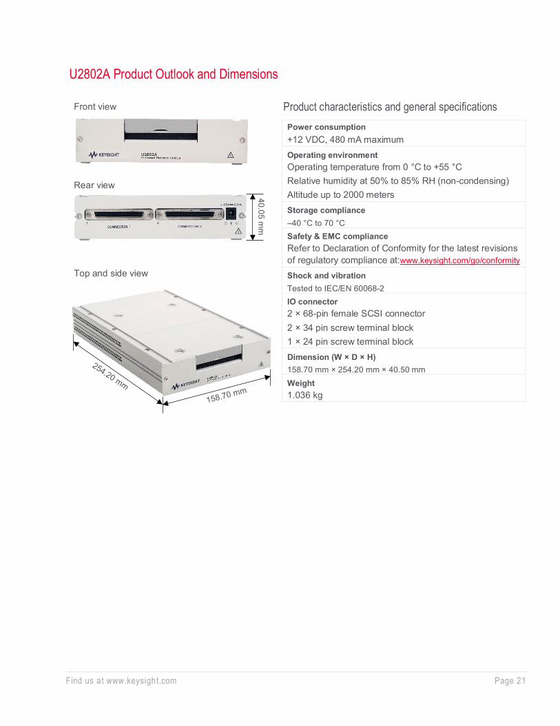
U2802A Product Outlook and Dimensions
Power consumption +12 VDC, 480 mA maximum Operating environment Operating temperature from 0 °C to +55 °C Relative humidity at 50% to 85% RH (non-condensing) Altitude up to 2000 meters Storage compliance –40 °C to 70 °C Safety & EMC compliance Refer to Declaration of Conformity for the latest revisions of regulatory compliance at:www.keysight.com/go/conformity Shock and vibration Tested to IEC/EN 60068-2 IO connector 2 × 68-pin female SCSI connector 2 × 34 pin screw terminal block 1 × 24 pin screw terminal block Dimension (W × D × H) 158.70 mm × 254.20 mm × 40.50 mm Weight 1.036 kg
Front view Product characteristics and general specifications
Rear view
40.05 mm
Top and side view

Find us at www.keysight.com Page 22
U2802A Product Specifications
1 The overvo ltage p ro tec t ion leve ls spec if ied above indicate the max imum vo ltage each inpu t p in can to le ra te w ithou t
resu lt ing in any damages . However, p ro longed exposure to these leve ls may affec t dev ice safety and rel iab il i ty . Hence , i t should be avo ided where possib le .
2 On the channe ls configu red fo r the rmocouple mode, the TC+ and TC– pins can tolerate up to ±17 V of d if feren tia l vo ltage for a few minutes. However, exceed ing a vo ltage range of ± 100 mV on these channe ls can cause add itiona l cu rren t to be drawn from the dev ice ’s power supp ly regula to rs , which may damage the dev ice if mu lt ip le channe ls a re overdriven fo r pro longed pe riods . Th is is the case when a vo ltage source is t ied ac ross the TCn+ and TCn– p in . Vo ltage sources g rea te r than ± 100 mV shou ld be tied to TCn+ and GND (f loa ting source ), o r TCn+ and TCn+1+ (g rounded source ), and have the channe ls se t for bypass mode .
General characteristics
Number of channels 31 differential and 1 CJC
Input voltage range for voltage mode ± 10 V (signal + common mode)
Input voltage (thermocouple mode) ± 100 mV
Sampling rate for thermocouple mode 10 kSa/s total for all channels
Sampling rate for overall module 500 kSa/s
Thermocouple types J, K, R, S, T, N, E, and B
Input specifications
Accuracy (thermocouple mode) Overall gain error Overall offset error Nonlinearity
0.06% (23 °C ± 5 °C) 15 μV (without zeroing) (23 °C ± 5 °C) 6 μV (with zeroing) < 0.005% of full scale range
System noise (rms) • Gain (× 1) • Gain (× 100)
100 μVrms 5 μVrms
Common Mode Rejection Ratio (CMRR) • Voltage mode • Thermocouple mode
> 60 dB > 80 dB
Cold junction accuracy ± 1.0 °C typical (23 °C ± 5 °C) ± 1.5 °C typical (0 °C to 18 °C, 28 °C to 55 °C)
Input characteristics
Bandwidth (voltage mode) > 500 kHz
Bandwidth (thermocouple mode) 4.0 Hz
Overvoltage protection 1 TC Mode 2 Common mode: ± 17 V (TC+ and TC– with respect to GND) Differential mode: ± 7 V (Differential voltage between TC+ and TC–) Bypass mode ± 20 V (TC+ input with respect to GND) Power-off Mode ± 11 V (TC+, TC– input with respect to GND)
Input impedance 1 G Ω
Input bias current ± 2.5 nA max
Input offset current ± 1.5 nA max

Find us at www.keysight.com Page 23
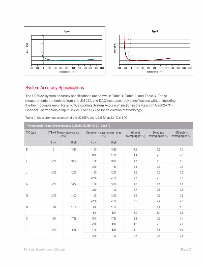
Thermocouples Typical Measurement Accuracy The U2802A measurement error with U2355A or U2356A at 23 °C ± 5 °C is shown below.
Gain drift 60 ppm/°C max
Offset drift 1 μV/°C max
Filter cutoff frequency (–3 dB) (thermocouple mode) 4.0 Hz
Filter type (thermocouple mode) Low Pass RC Filter
Other features
Recommended warm up time 30 minutes
Find us at www.keysight.com Page 24
System Accuracy Specifications The U2802A system accuracy specifications are shown in Table 1, Table 2, and Table 3. These measurements are derived from the U2802A and DAQ input accuracy specifications without including the thermocouple error. Refer to “Calculating System Accuracy” section in the Keysight U2802A 31-Channel Thermocouple Input Device User’s Guide for calculation methodology.
Table 1. Measurement accuracy of the U2355A and U2356A at 23 °C ± 5 °C
Thermocouple measurement accuracy (U2355A, U2356A at 23 °C ± 5 °C)
T/C type ITS-90 Temperature range (°C)
Optimum measurement range (°C)
Without averaging (± °C)
50 points averaging (± °C)
500 points averaging (± °C)
Low High Low High
B 0 1820 1100 1820 1.9 1.2 1.0
400 1100 4.4 2.5 2.0
E –270 1000 –150 1000 1.7 1.6 1.6
–200 –150 2.4 2.3 2.3
J –210 1200 –150 1200 1.6 1.5 1.5
–200 –150 2.7 2.6 2.5
K –270 1372 –100 1200 1.5 1.4 1.4
–200 –100 2.7 2.6 2.6
N –270 1300 –100 1300 1.5 1.3 1.3
–200 –100 3.0 2.7 2.6
R –50 1768 300 1760 2.0 1.4 1.3
–50 300 5.0 3.1 2.6
S –50 1768 400 1760 2.1 1.6 1.4
–50 400 4.5 2.8 2.4
T –270 400 –100 400 1.5 1.4 1.4
–200 –100 2.7 2.5 2.5

Find us at www.keysight.com Page 25
Table 2. Measurement accuracy of the U2355A at 0 to 18 °C and 28 to 45 °C
Thermocouple measurement accuracy (U2355A at 0 to 18 °C and 28 to 45 °C)
T/C type ITS-90 Temperature range (°C)
Optimum measurement range (°C)
Without averaging (± °C)
50 points averaging (± °C)
500 points averaging (± °C)
Low High Low High
B 0 1820 1100 1820 3.4 2.4 2.2
400 1100 7.5 3.6 2.2
E –270 1000 –150 1000 2.7 2.6 2.5
–200 –150 3.8 3.6 3.6
J –210 1200 –150 1200 2.5 2.4 2.4
–200 –150 4.2 4.0 3.9
K –270 1372 –100 1200 2.9 2.8 2.8
–200 –100 4.3 4.0 3.9
N –270 1300 –100 1300 2.6 2.5 2.5
–200 –100 4.9 4.2 4.0
R –50 1768 300 1760 3.8 3.1 3.0
–50 300 8.5 4.6 3.3
S –50 1768 400 1760 4.2 3.4 3.2
–50 400 7.7 4.2 3.1
T –270 400 –100 400 2.4 2.2 2.2
–200 –100 4.3 4.3 3.9

Find us at www.keysight.com Page 26
Table 3. Measurement accuracy of the U2356A at 0 to 18 °C and 28 to 45 °C
Thermocouple measurement accuracy (U2356A @ 0 to 18 °C and 28 to 45 °C)
T/C type ITS-90 Temperature range (°C)
Optimum measurement range (°C)
Without averaging (± °C)
50 points averaging (± °C)
500 points averaging (± °C)
Low High Low High
B 0 1820 1100 1820 6.1 3.1 2.4
400 1100 14.4 6.3 2.7
E –270 1000 –150 1000 3.0 2.6 2.6
–200 –150 4.2 3.7 3.6
J –210 1200 –150 1200 2.9 2.5 2.5
–200 –150 4.9 4.1 4.0
K –270 1372 –100 1200 3.3 2.9 2.9
–200 –100 5.3 4.2 4.0
N –270 1300 –100 1300 3.4 2.7 2.6
–200 –100 6.8 4.6 4.1
R –50 1768 300 1760 6.2 3.7 3.2
–50 300 15.7 7.2 3.8
S –50 1768 400 1760 6.4 4.0 3.4
–50 400 14.2 6.6 3.4
T –270 400 –100 400 3.0 2.4 2.2
–200 –100 5.3 4.2 3.9

Find us at www.keysight.com Page 27
Optional Accessories: U2901A/U2902A Terminal block and SCSI- II 68-pin connector with 1-meter/2-meter cable The U2901A/U2902A is a terminal block and SCSI-II 68-pin connector with 1 meter cable or 2 meter cable that can be used conjunction with the U2300A Series and U2500A Series.
Terminal block overview
Front view
85.20 mm
Side view
103.00 mm
42.96 mm
28.40 mm
Find us at www.keysight.com Page 28
Ordering Information
Optional accessories
Other Products in the Keysight USB Modular Data Acquisition (DAQ) Family
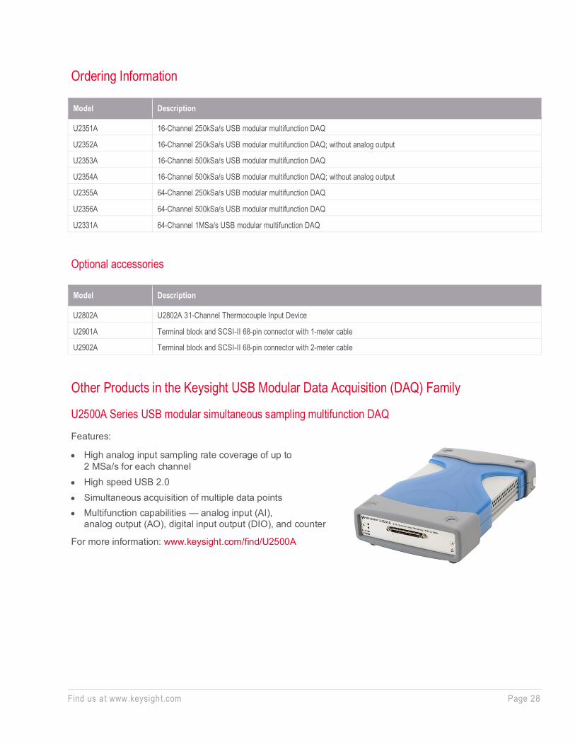
U2500A Series USB modular simultaneous sampling multifunction DAQ
Features:
• High analog input sampling rate coverage of up to 2 MSa/s for each channel
• High speed USB 2.0 • Simultaneous acquisition of multiple data points • Multifunction capabilities — analog input (AI),
analog output (AO), digital input output (DIO), and counter
For more information: www.keysight.com/find/U2500A
Model Description
U2351A 16-Channel 250kSa/s USB modular multifunction DAQ
U2352A 16-Channel 250kSa/s USB modular multifunction DAQ; without analog output
U2353A 16-Channel 500kSa/s USB modular multifunction DAQ
U2354A 16-Channel 500kSa/s USB modular multifunction DAQ; without analog output
U2355A 64-Channel 250kSa/s USB modular multifunction DAQ
U2356A 64-Channel 500kSa/s USB modular multifunction DAQ
U2331A 64-Channel 1MSa/s USB modular multifunction DAQ
Model Description
U2802A U2802A 31-Channel Thermocouple Input Device
U2901A Terminal block and SCSI-II 68-pin connector with 1-meter cable
U2902A Terminal block and SCSI-II 68-pin connector with 2-meter cable
Find us at www.keysight.com Page 29 This information is subject to change without notice. © Keysight Technologies, 2019 - 2021, Published in USA, August 25, 2021, 5991-0566EN
Learn more at: www.keysight.com For more information on Keysight Technologies’ products, applications or services, please contact your local Keysight office. The complete list is available at: www.keysight.com/find/contactus
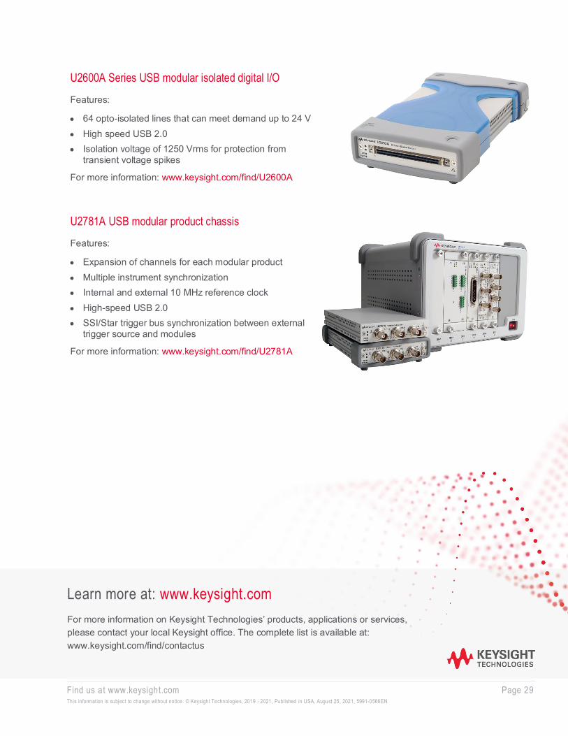
U2600A Series USB modular isolated digital I/O
Features:
• 64 opto-isolated lines that can meet demand up to 24 V • High speed USB 2.0 • Isolation voltage of 1250 Vrms for protection from
transient voltage spikes
For more information: www.keysight.com/find/U2600A
U2781A USB modular product chassis
Features:
• Expansion of channels for each modular product • Multiple instrument synchronization • Internal and external 10 MHz reference clock • High-speed USB 2.0 • SSI/Star trigger bus synchronization between external
trigger source and modules
For more information: www.keysight.com/find/U2781A