
U USSEERR MMAANNUUAALL AARRCC--KKIILLLLEERR SSVV … · The information provided herein is based on...
17
Moorstraat 24 - B-9850 Nevele - Belgium +32 (0)9 / 371 75 51 - fax +32 (0)9 / 371 59 25 - e-mail: [email protected] - website: www.deba.biz U U S S E E R R M M A A N N U U A A L L A A R R C C - - K K I I L L L L E E R R S S V V - - 2 2 5 5 S S V V 2 2 5 5 0 0 0 0 0 0 0 0 A A R R C C - - K K I I L L L L E E R R F F O O R R D D F F - - A A READ THIS DOCUMENT BEFORE OPERATION
Transcript of U USSEERR MMAANNUUAALL AARRCC--KKIILLLLEERR SSVV … · The information provided herein is based on...

Moorstraat 24 - B-9850 Nevele - Belgium +32 (0)9 / 371 75 51 - fax +32 (0)9 / 371 59 25 - e-mail: [email protected] - website: www.deba.biz
UUUSSSEEERRR MMMAAANNNUUUAAALLL AAARRRCCC---KKKIIILLLLLLEEERRR SSSVVV---222555
SSSVVV222555000000000000 AAARRRCCC---KKKIIILLLLLLEEERRR
FFFOOORRR DDDFFF---AAA
READ THIS DOCUMENT BEFORE OPERATION

AG646104 ARC-KILLER SV-25 (DF-A) P 2/17
© 2011 SGC nv - SwitchGear Company. All rights reserved. The information provided herein may not be reproduced and/or (re)published in any way and by any means (electronic or mechanical), without the prior, explicit written authorization of SGC nv - SwitchGear Company. The information provided herein is based on general data concerning the construction, known at the time of publication, and concerning the qualities of the material and working methods. Consequently, the right to make changes is reserved. The information contained within is applicable to the standard version of the DF-2 medium-voltage switchgear. Therefore, SGC nv - SwitchGear Company cannot be held liable for any damage resulting from specifications that differ from the standard version of the DF-2 medium-voltage switchgear. The available information has been assembled with the greatest possible care, but SGC nv - SwitchGear Company cannot be held liable for any mistakes in the information, or the consequences thereof. The user names, trade names, trademarks, etc., used by SGC nv - SwitchGear Company cannot, in accordance with the legislation concerning the protection of trademarks, considered to be free.

AG646104 ARC-KILLER SV-25 (DF-A) P 3/17

AG646104 ARC-KILLER SV-25 (DF-A) P 4/17
1. TABLE OF CONTENTS
1. TABLE OF CONTENTS _________________________________________________ 42. PREFACE ____________________________________________________________ 5
2.1. Related documentation _____________________________________________ 52.2. General safety directions and instructions ______________________________ 52.3. Intended Use ______________________________________________________ 5
3. TECHNICAL SPECIFICATION __________________________________________ 54. TRANSPORT AND STORAGE ___________________________________________ 55. OPERATIONAL PROCEDURE SV-25 _____________________________________ 6
5.1. Operational procedure during first operation ___________________________ 65.2. User procedure after an internal arc is interrupted by the arc-killer ________ 7
6. MAINTENANCE ______________________________________________________ 17

AG646104 ARC-KILLER SV-25 (DF-A) P 5/17
2. PREFACE This document is intended as a reference for qualified and trained operators to transport, operate and maintain the arc-killer in a safe an economical way. In the documentation the words “left”, “right”, “front” and “behind” are used to indicate a specific part of the arc-killer. The starting point is always the position of the operator, standing in front of the arc-killer, facing the arc-killer. 2.1. Related documentation The following technical documentation is available about the DF-2 medium-voltage switchgear:
− User Manual AG602601 − Spare Parts List AG608101 − Technical Brochure AG601103 (NL) or AG601204 (FR)
2.2. General safety directions and instructions The general applicable safety guidelines are included in full in the user manual AG602601, pages xi and xii. 2.3. Intended Use The arc-killer is designed exclusively to offer protection against the negative consequences of an internal arc in medium-voltage switchgear. Both in the cable and bus bar compartment.
3. TECHNICAL SPECIFICATION KEMA type tested according to IEC 60298 appendix AA all 6 criteria: arc extinguishing in less than 50ms.
4. TRANSPORT AND STORAGE The general applicable safety guidelines are included in full in the user manual AG602601, page 3-1. We reiterate that: Cubicles that fell over or have otherwise been damaged always HAVE TO BE RETURNED to DEBA nv for a checkup.
AG646104 ARC-KILLER SV-25 (DF-A) P 6/17
5. OPERATIONAL PROCEDURE SV-25 5.1. Operational procedure during first operation After the installation and before the actual putting into service of the medium-voltage cubicle:
− Observe whether the overpressure flaps at the rear of the cubicle are absolutely free of damage or distortion.
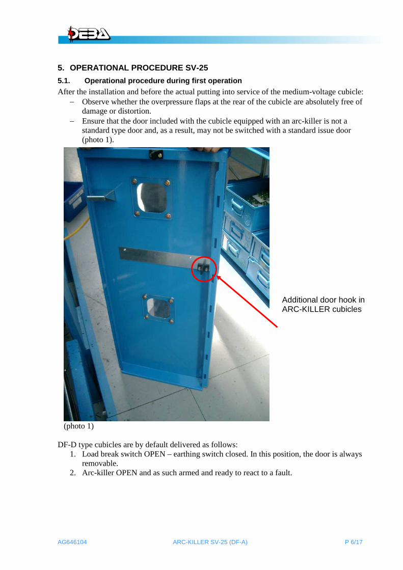
− Ensure that the door included with the cubicle equipped with an arc-killer is not a standard type door and, as a result, may not be switched with a standard issue door (photo 1).
(photo 1) DF-D type cubicles are by default delivered as follows:
1. Load break switch OPEN – earthing switch closed. In this position, the door is always removable.
2. Arc-killer OPEN and as such armed and ready to react to a fault.
Additional door hook in ARC-KILLER cubicles

AG646104 ARC-KILLER SV-25 (DF-A) P 7/17
Only if the arc-killer is in the open and not in position, can the cubicle be put into service according to the safety guidelines 5.1 on page 5.1 and the operating procedure 5.2.1.2 “Opening the earthing switch and closing the load break switch” on page 5-3 of the user manual AG602601. 5.2. User procedure after an internal arc is interrupted by the arc-killer The voltageless cubicle is now taken out of operation according to procedure 5.2.1.1 “Opening the load break switch and closing the earthing switch” on page 5-2 of the user manual AG602101. The door can now be opened. The arc-killer is resting on top of earthing blocks, earthed (see photo 2).
(photo 2)
The arc-killer is resting on top of the earthing knife blocks.

AG646104 ARC-KILLER SV-25 (DF-A) P 8/17
The following method can be executed in two ways, either with 1 or with 2 persons. With 2 persons, one operator will hold down the safety catch the entire duration of the procedure (see photo 3).
(photo 3)
The safety catch is held down during the entire procedure to re-arm the arc-killer
AG646104 ARC-KILLER SV-25 (DF-A) P 9/17
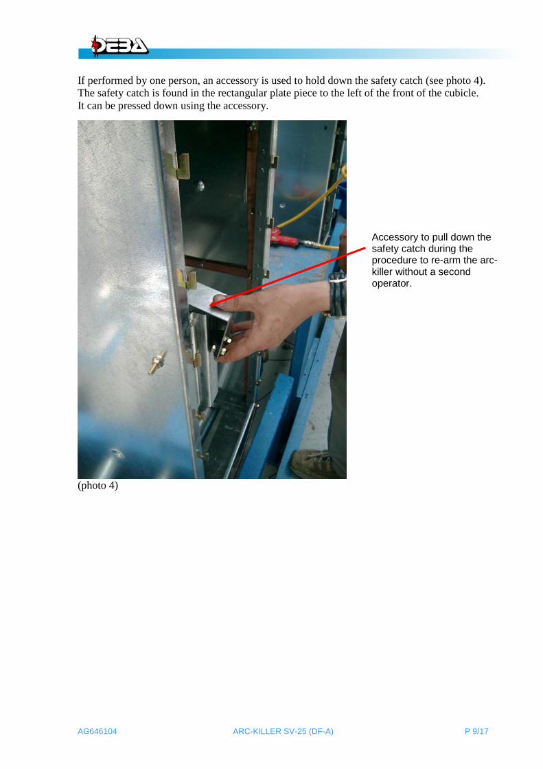
If performed by one person, an accessory is used to hold down the safety catch (see photo 4). The safety catch is found in the rectangular plate piece to the left of the front of the cubicle. It can be pressed down using the accessory.
(photo 4)
Accessory to pull down the safety catch during the procedure to re-arm the arc-killer without a second operator.

AG646104 ARC-KILLER SV-25 (DF-A) P 10/17
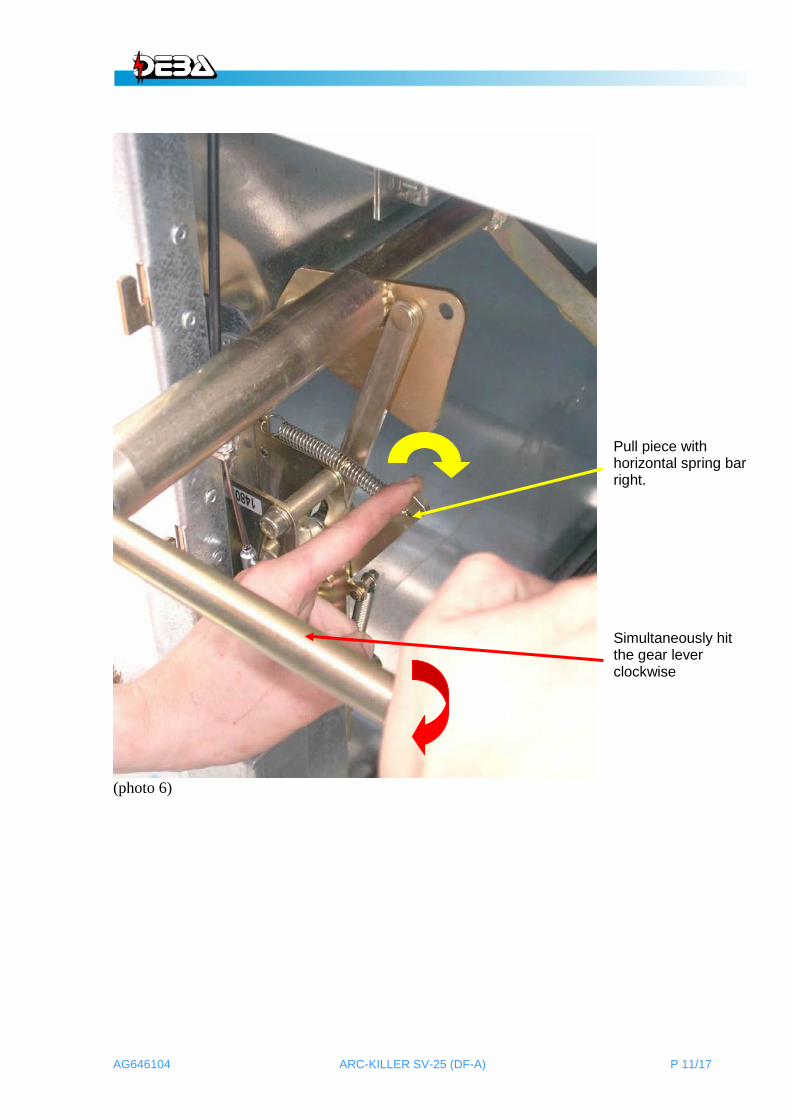
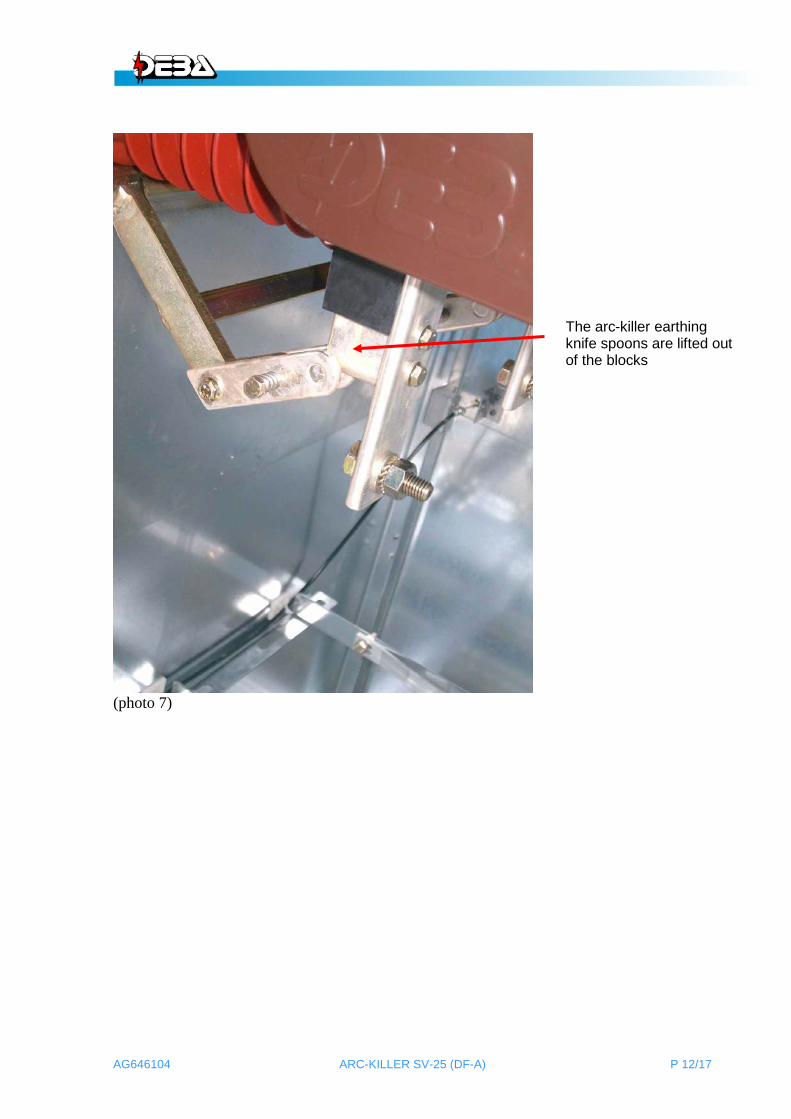
Now the second operator (in the case of 1 operator, the operator himself) places the switch bar on the visible main axis (see photo 5), pushes the upper part with a horizontal spring bar halfway right, AND simultaneously repeatedly hits the switch bar clockwise (see photo 6) to lift it out of the earthing knife blocks correctly (see photo 7).
(photo 5)
Place the gear lever on the main axis
AG646104 ARC-KILLER SV-25 (DF-A) P 11/17
(photo 6)
Pull piece with horizontal spring bar right.
Simultaneously hit the gear lever clockwise
AG646104 ARC-KILLER SV-25 (DF-A) P 12/17
(photo 7)
The arc-killer earthing knife spoons are lifted out of the blocks

AG646104 ARC-KILLER SV-25 (DF-A) P 13/17
Safety catch and gear lever can now be released. The gear lever continues to rest over the main axis. Just beyond the plate work container, just below the first vertical spring bar, a little bolt is affixed that needs to be pressed down clockwise until it stops. The gear lever can only then be pressed down clockwise and down as to open the earthing knife (photo 8).
photo 8
Push down bolt
Only then disabling the earthing knife clockwise with a gear lever

AG646104 ARC-KILLER SV-25 (DF-A) P 14/17
At the height of the bolt, a small axis with a milled flat area at the tip is affixed. While pressing down the bolt, simultaneously with a downward movement of the gear lever, a safety catch will appear next to the milled area. From then on out, the first bolt can be released (photo 9) and then, the gear lever can be removed. The arc-killer is now armed. The safety catch is now released in the plate piece container or the accessory is removed.
(photo 9)
The safety catch is back in its place
Release bolt
Axis with milled area

AG646104 ARC-KILLER SV-25 (DF-A) P 15/17
− If possible, remedy the cause of the internal arc. − Check the condition of the arc-killer contacts and earthing knife blocks. They cannot
be burned in severely. − If necessary, remove carbon black on the isolators and the poles. − Clean the arc killer’s earthing knife spoons and earthing blocks and regrease these
components with a 0.5 mm, evenly applied layer of DEBA grease (order number GR002002).
− It is recommended to perform a 1 min. 38 kV «power frequency withstand test» to evaluate the status of the entire medium-voltage switchgear.
After solving the cause and after testing, the medium-voltage cubicle is ready for operation, provided that the overpressure flaps at the rear are back to their original position and the cable connections are still intact (see photos 10-11).
(photo 10)
Rear of the cubicle
Cable connection

AG646104 ARC-KILLER SV-25 (DF-A) P 16/17
(photo 11)
Rear of the cubicle
Cable connection in equipment compartment
RV44 gas-filled switch
AG646104 ARC-KILLER SV-25 (DF-A) P 17/17
6. MAINTENANCE The general maintenance guidelines, and maintenance procedures that apply here are fully included in user manual AG602601, pages 6-1 & 6-2. The procedure 6.2.3 “greasing the earthing knife spoons and earthing blocks” on page 6-5 applies to the arc-killer as well as the standard earthing knife.
As soon as the door of the medium-voltage cubicle is removed, the arc-killer is blocked. Maintenance work can then be carried out safely.


![An efficient spectral method for computing dynamics of ...web.mst.edu/~zhangyanz/Papers/Ju-Tang-Zhang-2014.pdf · 0,with/withoutexternaldrivingfield [5,8,14,37,28].Amongthem,thetime-splittingpseudo-spectralmethod](https://static.fdocuments.net/doc/165x107/5ec5ccd5fe35f6435831c613/an-efficient-spectral-method-for-computing-dynamics-of-webmsteduzhangyanzpapersju-tang-zhang-2014pdf.jpg)


