U series-installation-instructions-us
4
INSTALLATION & OPERATING INSTRUCTIONS INSTALLATION & OPERATING INSTRUCTIONS EST. 1947 1-800-226-8710 / [email protected] / www.montalvo.com Technical details subject to change without notice. IO-U-series-US-02 © Montalvo U-Series Under Pillow Block Load Cells General Description Montalvo’s U-Series are used in conjunction with pillow block mounted bearings and shaft to create a durable and precise tension roller that’s easy to install. With an IP67 rating the U-Series offers an extreme level of protection and performance for applications in harsh environments. Principals of Operation The sensing element of each load cell consists of a pair of semiconductor strain gages configured to form half of a Wheatstone bridge. The load cells are excited by a stabilized DC voltage from an external electronic control circuit. When there is no force applied on to the load cell, the bridge is in a balanced state and hence the output signal will be near zero. On applying force, due to bending stress on the sensing element, resistance on the strain gauges change. This results in a corresponding change in output signal from the load cells. This signal is amplified to suitable working levels by the external electronic amplifier. Installation 1 It is recommended that the tension sensing roller be the middle roller in a tri-idler-roll assembly. The wrap angle around the sensing roller should not change during the installation process. 2 U-Series are mounted in pairs, one at each end of a sensing roller. 3 Both load cells must face the same direction (observe cables as they exit the load cells). The label on the load cell assures proper alignment with respect to resultant force Fres (load direction). 4 Use caution when selecting and installing the bearing bolts. Bolts that are too long will damage the load cell. Make sure they are the proper length (see Dimensions). 5 Wire each load cell to the controller or amplifier using shielded 4 conductor cable. The cable will require a female 4 pin M12 connector at one end to connect to the male U-Series connector. 6 For additional wiring, calibration and tuning, refer to controller or amplifier instruction manual. Fres bearing roller web web Product label indicates allowable range that direction of load (resultant force Fres) must fall within. Guiding Rollers Load Cells (note that connectors face same direction) Sensing Roller Male M12 Load Cell Connectors Female M12 Cable Connectors Shielded 4 Conductor Cables to Conrtroller or Amplifier Pillow Block Bearing Pillow Block Bearing
-
Upload
bwmontalvo -
Category
Business
-
view
93 -
download
0
Transcript of U series-installation-instructions-us
INST
ALLA
TIO
N &
OPE
RAT
ING
INST
RU
CTI
ON
SIN
STAL
LATI
ON
& O
PER
ATIN
G IN
STR
UC
TIO
NS
EST. 1947
1-800-226-8710 / [email protected] / www.montalvo.comTechnical details subject to change without notice. IO-U-series-US-02 © Montalvo
U-Series Under Pillow Block Load Cells
General Description
Montalvo’s U-Series are used in conjunction with pillow block
mounted bearings and shaft to create a durable and precise
tension roller that’s easy to install. With an IP67 rating the U-Series
offers an extreme level of protection and performance for
applications in harsh environments.
Principals of Operation
The sensing element of each load cell consists of a pair of semiconductor strain gages confi gured
to form half of a Wheatstone bridge. The load cells are excited by a stabilized DC voltage from an
external electronic control circuit. When there is no force applied on to the load cell, the bridge is in a
balanced state and hence the output signal will be near zero.
On applying force, due to bending stress on the sensing element, resistance on the strain gauges
change. This results in a corresponding change in output signal from the load cells. This signal is
amplifi ed to suitable working levels by the external electronic amplifi er.
Installation
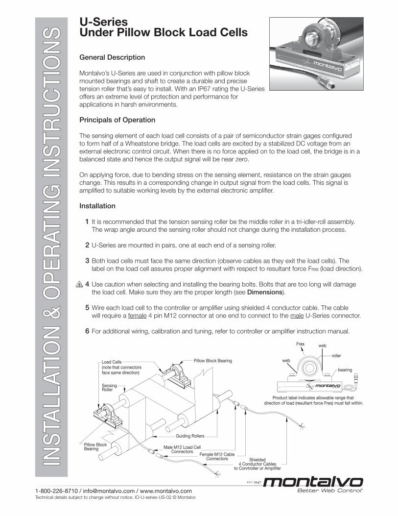
1 It is recommended that the tension sensing roller be the middle roller in a tri-idler-roll assembly.
The wrap angle around the sensing roller should not change during the installation process.
2 U-Series are mounted in pairs, one at each end of a sensing roller.
3 Both load cells must face the same direction (observe cables as they exit the load cells). The
label on the load cell assures proper alignment with respect to resultant force Fres (load direction).
4 Use caution when selecting and installing the bearing bolts. Bolts that are too long will damage
the load cell. Make sure they are the proper length (see Dimensions).
5 Wire each load cell to the controller or amplifi er using shielded 4 conductor cable. The cable
will require a female 4 pin M12 connector at one end to connect to the male U-Series connector.
6 For additional wiring, calibration and tuning, refer to controller or amplifi er instruction manual.
Fres
bearing
rollerweb
web
Product label indicates allowable range that direction of load (resultant force Fres) must fall within.
Guiding Rollers
Load Cells(note that connectors face same direction)
SensingRoller
Male M12 Load CellConnectors
Female M12 CableConnectors Shielded
4 Conductor Cablesto Conrtroller or Amplifier
Pillow Block Bearing
Pillow Block Bearing
EST. 1947
U-Series Under Pillow Block Load CellsInstallation and Operation
1-800-226-8710 / [email protected] / www.montalvo.comTechnical details subject to change without notice. IO-U-series-US-02 © Montalvo
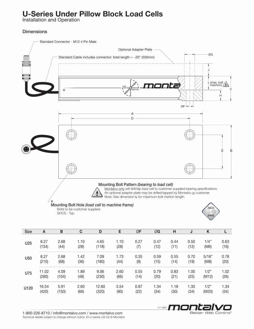
B
C
J
L (max. bolt insertion)
H
E
D
K
A
ØG
ØF
A B C D E ØF ØG H J K L
8.27 2.68 1.10 4.65 1.10 0.27 0.47 0.44 0.50 1/4” 0.63 (134) (44) (28) (118) (28) (7) (12) (11) (12) (M6) (16)
8.27 2.68 1.42 7.09 1.73 0.35 0.59 0.55 0.70 5/16” 0.78 (210) (68) (36) (180) (44) (9) (15) (14) (19) (M8) (20) 11.02 4.09 1.89 9.06 2.60 0.55 0.79 0.83 1.00 1/2” 1.02 (280) (104) (48) (230) (66) (14) (20) (21) (25) (M12) (26) 16.54 5.91 2.60 12.60 3.54 0.87 1.34 1.18 1.30 1/2” 1.34 (420) (150) (66) (320) (90) (22) (34) (30) (34) (M20) (34)
Size
U25
U50
U75
U120
Mounting Bolt Hole (load cell to machine frame) Bolts to be customer supplied.
SHCS - Typ.
Optional Adapter Plate
Mounting Bolt Pattern (bearing to load cell) Montalvo only will drill/tap load cell to customer supplied bearing specifications.
An optional adapter plate may be drilled/tapped by Montalvo or customer.
Note: See dimension L for maximum bolt insrtion length.
Standard Cable includes connector: total length = ~20” (500mm)
Standard Connector - M12 4 Pin Male
Dimensions
EST. 1947
U-Series Under Pillow Block Load CellsInstallation and Operation
1-800-226-8710 / [email protected] / www.montalvo.comTechnical details subject to change without notice. IO-U-series-US-02 © Montalvo
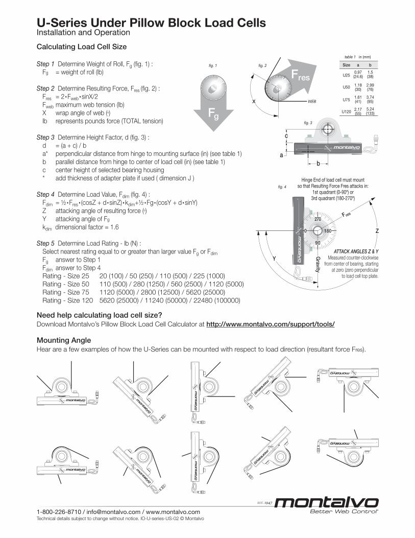
Step 1 Determine Weight of Roll, Fg (fig. 1) :
Fg = weight of roll (lb)
Step 2 Determine Resulting Force, Fres (fig. 2) :
Fres = 2.Fweb.sinX/2
Fweb maximum web tension (lb)
X wrap angle of web (º)
lb represents pounds force (TOTAL tension)
Step 3 Determine Height Factor, d (fig. 3) :
d = (a + c) / b
a* perpendicular distance from hinge to mounting surface (in) (see table 1)
b parallel distance from hinge to center of load cell (in) (see table 1)
c center height of selected bearing housing
* add thickness of adapter plate if used ( dimension J )
Step 4 Determine Load Value, Fdim (fig. 4) :
Fdim = ½.Fres.(cosZ + d.sinZ).kdim+½.Fg.(cosY + d.sinY)
Z attacking angle of resulting force (º)
Y attacking angle of Fg
kdim dimensional factor = 1.6
Step 5 Determine Load Rating - lb (N) :
Select nearest rating equal to or greater than larger value Fg or Fdim
Fg answer to Step 1
Fdim answer to Step 4
Rating - Size 25 20 (100) / 50 (250) / 110 (500) / 225 (1000)
Rating - Size 50 110 (500) / 280 (1250) / 560 (2500) / 1120 (5000)
Rating - Size 75 1120 (5000) / 2800 (12500) / 5620 (25000)
Rating - Size 120 5620 (25000) / 11240 (50000) / 22480 (100000)
Fg
Fres
X
ab
c
Z
Y
9 0
180
270
0
Hinge End of load cell must mountso that Resulting Force Fres attacks in:
1st quadrant (0-90º) or3rd quadrant (180-270º)
F res
Gravity
fig. 1 fig. 2
WEB
fig. 3
table 1 in (mm)
fig. 4
ATTACK ANGLES Z & YMeasured counter-clockwise
from center of bearing, starting
at zero (zero perpendicular
to load cell top plate.
a
0.97(24.6)
1.18(30)
1.61(41)
2.17(55)
Size
U25
U50
U75
U120
b
1.5(38)
2.99(76)
3.74(95)
5.24(133)
Calculating Load Cell Size
Mounting AngleHear are a few examples of how the U-Series can be mounted with respect to load direction (resultant force Fres).
Need help calculating load cell size?Download Montalvo’s Pillow Block Load Cell Calculator at http://www.montalvo.com/support/tools/
EST. 1947
ElectricalSupply voltage...........................................................................5 VDC
Output...................................................... 250 mV, nominal @ full load
Gauge: Resistance .........................................................80 - 130 Ω
Type .......................................................... semi-conductor
Non-Repeatability .......................................................±0.2% full span
Non-Linearity & hysteresis (combined) ........................±0.5% full span
Connector (standard)
Type ............................................................................Male 4 pin M12
Pin 1.....................................................................................Excitation
Pin 2.......................................................................................... Signal
Pin 3............................................................................. No connection
Pin 4.....................................................................................Excitation
Cable length (including connector) ............................... 20 in. (500mm)
Non-standard cable (optional)............................................. By request
No connector (optional) ...................................................... By request
Load Rating* lb (N)
25 .................................... 20 (100) / 50 (250) / 110 (500) / 225 (1000)
50 .......................... 110 (500) / 280 (1250) / 560 (2500) / 1120 (5000)
75 ................................... 1120 (5000) / 2800 (12500) / 5620 (25000)
120 ......................... 5620 (25000) / 11240 (50000) / 22480 (100000)
Overload Rating lb (N)
25 ......................................................................................675 (3000)
50 .................................................................................3660 (15000)
75 ...............................................................................16860 (75000)
120 ...........................................................................67440 (300000)
Overload stops ................................................... Factory set @ 110%
* Recommended that Montalvo be contacted to ensure proper sizing.
EnvironmentalEnclosure protection class...........................................................IP 67
Operating temp. °F (°C) ..................................-4 to +185 (-20 to +85)
Mechanical in (mm)
Deflection (at nominal force) ............... 0.005 to 0.010 (0.3 to 0.25) typ.
Material ......................................................................... stainless steel
Material Option (for U25 only) ...............................................aluminum
Dimensions in (mm)
25 ................................................. 5.28 x 1.73 x 1.10 (134 x 44 x 28)
50 ................................................ 8.27 x 2.68 x 1.42 (210 x 68 x 36)
75 .............................................. 11.02 x 4.09 x 1.89 (280 x 104 x 48)
120 ........................................... 16.54 x 5.91 x 2.60 (420 x 150 x 66)
Weight lb (kg) approx. (does not include bearing or optional adapter)
25 ..........................................................................................2.5 (1.1)
50 .............................................................................................6 (2.5)
75 ..............................................................................................18 (8)
120 ..........................................................................................60 (26)
BearingsSelf-aligning.................................................................Recommended
207-856-2501 / 800-226-8710+86-21-61401822+45 75 57 27 11
www.montalvo.com/contacts
U-Series Under Pillow Block Load CellsInstallation and Operation
1-800-226-8710 / [email protected] / www.montalvo.comTechnical details subject to change without notice. IO-U-series-US-02 © Montalvo
Specifi cations
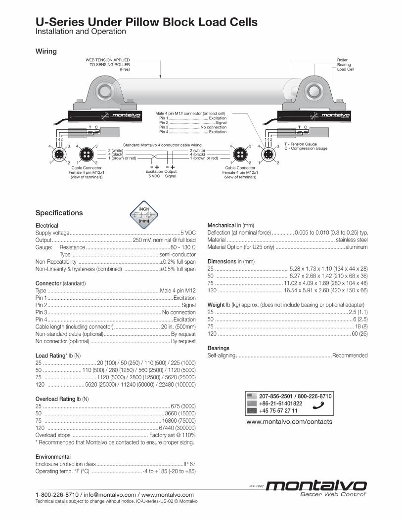
Wiring
T - Tension GaugeC - Compression Gauge4
21
3 4
21
2 (white)4 (black)1 (brown or red)
2 (white)4 (black)1 (brown or red)
3 4
21
3 4
21
3
Male 4 pin M12 connector (on load cell) Pin 1.................................... Excitation Pin 2 ......................................... Signal Pin 3.............................No connection Pin 4.................................... Excitation
WEB TENSION APPLIEDTO SENSING ROLLER
(Fres)
RollerBearingLoad Cell
T C
1 4 2
T C
1 4 2
OutputSignal
Excitation5 VDC
Cable ConnectorFemale 4 pin M12x1(view of terminals)
Cable ConnectorFemale 4 pin M12x1(view of terminals)
- +- +
Standard Montalvo 4 conductor cable wiring