u. s. c., - Lehigh Universitydigital.lib.lehigh.edu/fritz/pdf/490_7.pdf · u. s. Department of...
13
I I I I I I I I I I I I I I I I I I I FRITZ ENGINEERING LABORATORY LIBRARY Prepared For u. s. Department of Transportation Federal Highway Administration Office of Research and Technology Washington, D. c., 20590 WIM+RESPONSE HARDWARE By John L. Wilson J. Hartley Daniels L. Y. Lai R. Abbaszadeh Department of Civil Engineering Fritz Engineering Laboratory, Bldg. No. 13 LEHIGH UNIVERSITY Bethlehem, PA., 18015 March 1986 Fritz Engineering Laboratory Report No. 490.7
Transcript of u. s. c., - Lehigh Universitydigital.lib.lehigh.edu/fritz/pdf/490_7.pdf · u. s. Department of...
I I I I I I I I I I I I I I I I I I I
FRITZ ENGINEERING
LABORATORY LIBRARY
Prepared For u. s. Department of Transportation
Federal Highway Administration Office of Research and Technology
Washington, D. c., 20590
WIM+RESPONSE HARDWARE
By
John L. Wilson J. Hartley Daniels
L. Y. Lai R. Abbaszadeh
Department of Civil Engineering Fritz Engineering Laboratory, Bldg. No. 13
LEHIGH UNIVERSITY Bethlehem, PA., 18015
March 1986
Fritz Engineering Laboratory Report No. 490.7
I I I I I I I I I I I I I I I I I I I
TABLE OF CONTENTS
1. INTRODUCTION
2. FUNCTIONAL DESCRIPTION OF WIM+RESPONSE HARDWARE
2.1 MINC 11-23 Minicomputer
2.2 VT 125 Graphics Terminal
2.3 LA 50 Printer
2.4 WIM Conditioner
2.5 RESPONSE Conditioner
2.6 WIM Transducers
2.7 RESPONSE Strain Gages
2.8 Tapeswitches
2.9 Keypad (K-Box)
2.10 Frequency Meter
2.11 Clamps
2.12 External Power Supply
Page
1
1
1
2
3
3
4
4
5
8
9
9
11
12
I I I I I I I I I I I I I I I I I I I
WIM+RESPONSE HARDWARE
1 . Introduction
The purpose of this manual is to provide technical pers onnel with the characteristics of the use of all equipment (hardware) associated with the WIM+RESPONSE system . Each segment of this section contains the following information : a description of the component ; what it is used for ; what it includes or contains ; what are its characteristics; and where additional information or details can be found . Pictures of equipment are included for clarity wherever appropriate.
2 . Functional Description of WIM+RESPONSE Hardware
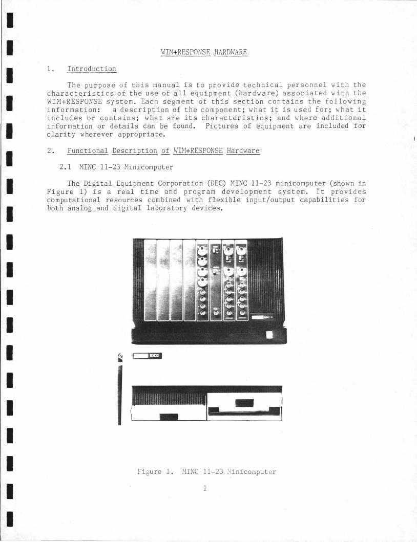
2 . 1 MINC 11-23 Minicomputer
The Digital Equipment Corporation (DEC) MINC 11-23 minicomputer (shown in Figure 1) is a real time and program development system . It provides computational resources combined with flexible input/output capabilities for both analog and digital laboratory devices.
,., .~e
-Figure 1. HI NC 11- 23 ~!inicomput er
1
I I I I I I I I I I I I I I I I I I I
This single-user system has 256k, 16 bit, words of memory and contains the RT-ll VS operating system along with two 8" inch disk drives (RX02) which are designated as disk drive 0 (left) and disk drive 1 (right) as shown in Figure 1. The system also contains the DECLAB-ll/NNC integrated system for data acquisiton, data manipulation , and monitoring. The DECLAB-11/NNC includes: 2 clock modules, 1 digital input module, and 1 A/D converter module.
Should the reader require more detailed information, the NINC 11-23 is well documented in available documentation from DEC as follows:
a) Introduction to RT-11 (RT-11, Volume 1A): This manual presents the background material necessary to understand the system and its operations.
b) DECLAB-11/NN user's guide: This manual provides the information necessary for connecting the system to peripheral systems required to monitor and/or control.
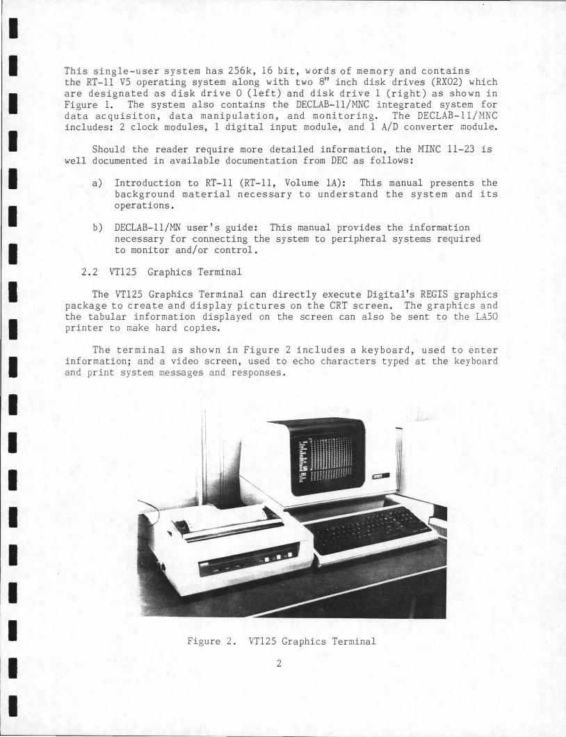
2.2 VT125 Graphics Terminal
The VT125 Graphics Terminal can directly execute Digital's REGIS graphics package to create and display pictures on the CRT screen. The graphics and the tabular information displayed on the screen can also be sent to the LASO printer to make hard copies.
The terminal as shown in Figure 2 includes a keyboard, used to enter information; and a video screen, used to echo characters t yped at the keyboard and print system messages and responses.
Figure 2. VT125 Graphics Terminal
2

I I I I I I I I I I I I I I I I I I I
Should the reader require more detailed information, the following DEC documentation is recommended:
VT125 Graphics Terminal User Guide: This manual provides general operating information, interface information, control functions and REGIS command descriptors, and installation and checkout procedures.
2.3 LASO Printer
The LASO is a dot-matrix, serial printer. The printer receives characters and commands through an asynchronous serial interface connected to the VT125 CRT. The printer operates in either of two modes: text mode or graphics mode. In text mode, the printer prints characters in a 16-dot character cell at 50 characters per second. In graphics mode, the printer allows the programmer to print graphic images by sending data that controls the dot printing format.
The printer uses a ribbon cartridge and 8 1/2" wide paper.
Should the reader require more deailed information, the following DEC documentation is recommended:
a) Installing and Using the LASO Printer: This document provides the information necessary to install, use, maintain, troubleshoot and configure the LASO printer.
b) LASO Printer Programmer Reference Manual: This document provides the information necessary for the programmer to control the printing format.
2.4 WIM Conditioner
The WIM conditioner (shown in top of Figure 3) is the system used to condition high-level analog signals from WIM transducers and digital signals from the tapeswitches and the keypad. The conditioned output signals are to be stored on the floppy disk for future analysis.
The WIM conditioner contains the following: three Vishay 2120 conditioner modules (6 channels), 1 Vishay 2110 power supply module, keypad signal conditioning and tapeswitch conditioning.
Should the reader require more detailed information, the following Vishay documentation is recommended.
1. 2100 System Strain Gage Conditioner and Amplifier System: This document provides the information necessary for the use of Vishay conditioning systems.
2. BWS (Bridge Weighing Systems) Manual-Conditioning Center.
3

I I I I I I I I I I I I I I I I I I I
Figure 3. WIM and RESPONSE Conditioners
2 . 5 RESPONSE Conditioner
The RESPOt'SE conditioner (shown in bottom of Figure 3) is the system used to condition high-level analog signals from response strain gages .
The RESPONSE conditioner contains the Vishay complete 10- channel 2100 system ,
Should the reader require more detailed information, the following Vishay documentation is recommended :
2100 System Strain Gage Conditioner and Amplifier System : This document provides the information necessar y for the use of Vishay conditioning systems .
2 . 6 WIM Tr ansducers
The WIM t r ansducers (shown in Fi gure 4 on the next page) a r e used to measure strain signals for either weigh-in- motion or response analysis . The
4

I I I I I I I I I I I I I I I I
I
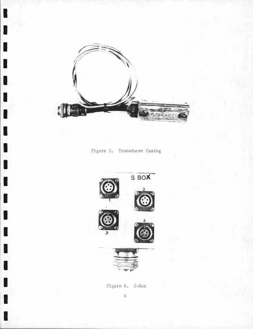
transducers are enclosed in a protective casing , shown in Figure 5. Each transducer is composed of 4 strain gages and , therefore, it is much more sensitive and fragile than a single strain gage. The first 4 transducers are connected to the S- box. The S- box will then be connected to the WIM conditioner (as discussed in the "WIM+RESPONSE TRAINING GUIDE", FHWA/RD-86/04 7. The other 2 transducers are directly connected to WIM conditioner through analog cables. The S-Box is shown in Figure 6.
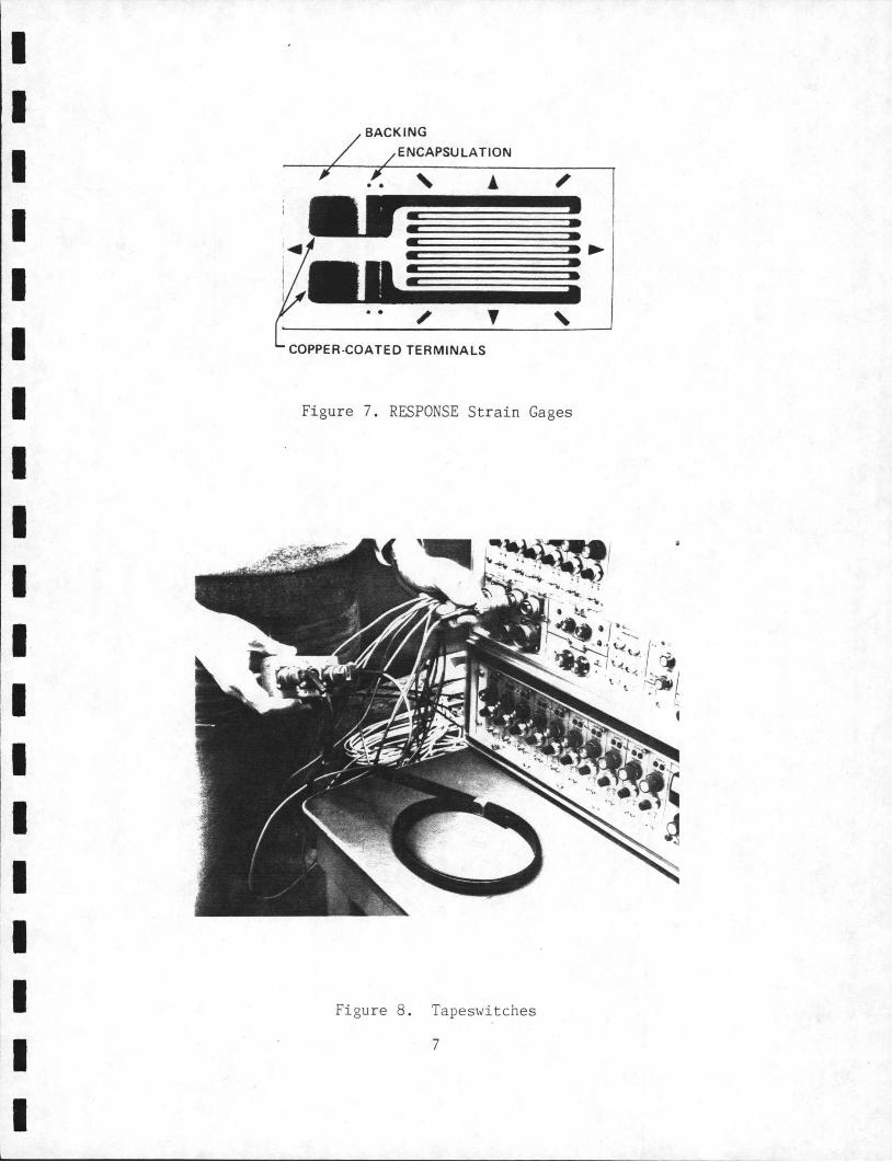
2 . 7 RESPONSE Strain Gages
The RESPONSE strain gages shown in Figure 7 are used to measure strain signals for response only . The strain gages are connected to the RESPONSE conditioner through analog cables.
As with the Transducers, it is highly recommended that experienced personnel attach and secure the strain gages on clean surfaces.
Figure 4. WIM Transducers
5
I I I I I I I I I I I I I I I I I I
t•
Figure 5. Transducer Casing
Figure 6. S-Box
6
I I I I I I I I I I I I I I
I I
BACK ING
ENCAPSULATION
. . ' !
COPPER -COATED TERMINALS ' Figure 7. RESPONSE Strain Gages
Figure 8 . Tapeswitches
7

I I I I I I I I I I I I I I I I I I I
2.8 Tapeswitches, T-Box, D-Box
The tapeswitches shown in Figure 8 are used to detect the arrival of vehicle axles. The tapeswitches can only be connected to T-boxes. The T-box acts as an intermediate connector between tapeswitches and a K-Box or D-Box and the WIM conditioner. The D-box acts as an intermediate connector between the tapeswitches, keypad and the WIM conditioner.
Figures 9, 10 show the T-Box and D-Box respectively.
xom· -1
TSOUT TS2-4 TS1-3
Figure 9 . T-Box
D BOX
OUTPUT
KEYPAD
- - • -----.-..::,.- r......- · --· .....
Fi gure 10. D-Box
8

I I I I I I I I I I I I I I I I I I I
2.9 Keypad (K-box)
The keypad shown in Figure 11 on the next page is used to identify the traffic lane in which the vehicle is travelling and a category of truck such as flat, auto carrier . The keypad can either be directly connected to the WIM conditioner or connected through a D-Box.
The keypad contains 16 buttons, each of them can produce a digital signal which can be used to identify truck type and traffic lane. The K-box can also be used as the intermediate connector between a T-Box and the WIM conditioner.
2 .10 Frequency Meter
The frequency meter shown in Figure 12, is used to measure the AC power frequency to ensure the proper functioning of the computer. The frequency should be at or near 60 Hz.
~~------~------KBOX
OUTPU~ ·
Figure 11. K-Box (Keypad)
9

I I I I I I I I I I I I I I I I I I I
FREQuENCY METER
MIN 55 60 65
, Hz 't
Figure 12 . Frequency Meter
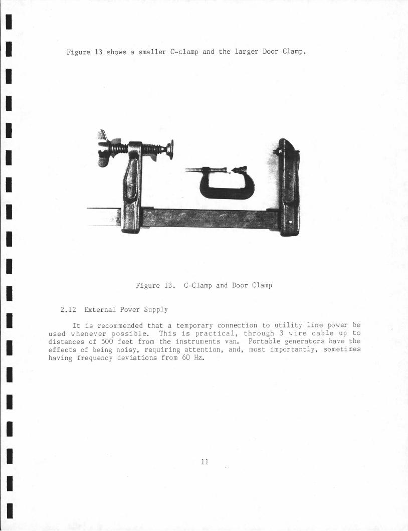
2.11 Clamps (C-Clamps and Door-Clamps)
The C-clamps are used to secure the transducers on the flanges of steel girders to the bridge .
The lar ger Door -cl amps are used to secure the transducers on concrete girders of the bridge .
10
I I I I I I I I I I I I I I I I I I I
Figure 13 shows a smaller C-clamp and the larger Door Clamp.
Figure 13. C-Clamp and Door Clamp
2. 12 Ex ternal Power Supply
It is recommended that a temporary connection to utility line power be used wheneve r possible . This is practical, through 3 wire cable up to distances of 500 feet from the instruments van. Portable generators have the effects of being noisy , requiring attention, and, most importantly, sometimes having frequency dev iations from 60 Hz.
11