
U NIVERSITY OF TURKU Modeling of DVB-H Link Layer Heidi Joki Deparment of Information Technology...
35
UNIVERSITY OF TURKU Modeling of DVB-H Link Layer Heidi Joki Deparment of Information Technology University of Turku Supervisor: Professor Jorma Virtamo Instructor: Jarkko Paavola, M.Sc.
-
date post
20-Dec-2015 -
Category
Documents
-
view
215 -
download
1
Transcript of U NIVERSITY OF TURKU Modeling of DVB-H Link Layer Heidi Joki Deparment of Information Technology...

UNIVERSITY OF TURKU
Modeling of DVB-H Link Layer
Heidi Joki
Deparment of Information TechnologyUniversity of Turku
Supervisor: Professor Jorma VirtamoInstructor: Jarkko Paavola, M.Sc.

10.5.2005 Heidi Joki 2
UNIVERSITY OF TURKU
Agenda
• Background: Why was DVB-H developed?• Services• From DVB-T to DVB-H• The DVB-H system• DVB-H standards family• Presentation of the DVB-H Link Layer• Simulation model• Simulation results• New decoding algorithms• Conclusions• Further work

10.5.2005 Heidi Joki 3
UNIVERSITY OF TURKU
Background: Why was DVB-H developed?
• There was a wish to bring TV-like services to mobile phones
• UMTS does not fulfil requirements for high bandwidth Internet applications, such as streaming video
• Mobile broadcasting is the best way to reach many users with reasonable cost
• DVB-T is not suitable for handheld battery powered devices

10.5.2005 Heidi Joki 4
UNIVERSITY OF TURKU
Services• Real time applications
– TV broadcasting, info linked to events, games or quizzes
• Data carousel applications– Like teletext; stocks, weather, sports
• File Download– Buy newspaper, tourist map of city
• DVB-H in mobile phones => cellular network as return channel for interactivity, billing and authentication

10.5.2005 Heidi Joki 5
UNIVERSITY OF TURKU
From DVB-T to DVB-H
• DVB-H is amendment of DVB-T for handheld devices
• Lower power consumtion in the receiver• More flexibilyty in network planning• Technical changes:
– Time-slicing (Link layer)– MPE-FEC (Link layer)– 4K OFDM mode (Physical layer)– IP datacast (Network layer)– Signaling
10.5.2005 Heidi Joki 6
UNIVERSITY OF TURKU
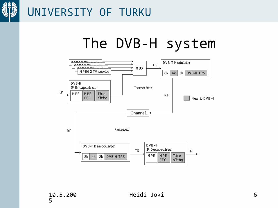
MPEG2 TV serviceMPEG2 TV service
MPEG2 TV serviceMPEG2 TV service
MUX
DVB-H IP Encapsulator
MPE MPE-FEC
Timeslicing
IP
DVB-H IP Decapsulator
MPE MPE-FEC
Timeslicing
DVB-T Modulator
8k 4k DVB-H TPS2k
DVB-T Demodulator
8k 4k DVB-H TPS2k
Channel
TS
RF
RF
TS IP
Transmitter
Receiver
New to DVB-H
The DVB-H system

10.5.2005 Heidi Joki 7
UNIVERSITY OF TURKU

10.5.2005 Heidi Joki 8
UNIVERSITY OF TURKU
Presentation of the DVB-H Link Layer
• Link Layer Packets (TX)• Time-Slicing• MPE-FEC• Reed-Solomon(255,191)• MPE- and FEC-sections • Transport Stream• Section parsing and Decapsulation (RX)• Erasure Decoding (RX)

10.5.2005 Heidi Joki 9
UNIVERSITY OF TURKU
Link Layer Packets (transmitter)IP header (20B) Payload (0-1480B)
Last punctured RS
column
...
First punctured R
S colum
n
Parity b
ytes in last FE
C section
..
Parity b
ytes carried in section 2
Parity b
ytes carried in section 1
Last data padding column
..
First data padding colum
n
Last IP datagram
Padding b
ytes
...
2nd IP dg cont.. 3rd IP
dg
1st IP dg cont. 2nd IP
datagram
1st IP datagram
1
1
Nbr of rows256, 512,
786 or 1024
191 1 64Application data table RS data table
MPE-FEC header (12B) Column (max 1024B) CRC-32 (4B)
Network Layer:IP datagram
LLC sublayer:MPE-FEC frame
MAC sublayer:MPE and MPE-FEC sections
(Header includes 4BReal time parameters)
MPE header (12B) IP datagram CRC-32 (4B)
TS Header (4B) Payload (184B) TS Header (4B) Payload (184B)... ...
MPEG-2 Transport Stream

10.5.2005 Heidi Joki 10
UNIVERSITY OF TURKU
• Data sent in bursts, one burst per MPE-FEC frame
• Enables power saving (≤90%)• Delta-t, time to start of next burst, is
announced in the section header• No separate synchronization needed;
Receiver clock has to be stable only until next burst
• Supports use of receiver for network monitoring during off-periods
Time-slicing

10.5.2005 Heidi Joki 11
UNIVERSITY OF TURKU
MPE-FEC in TX (1/2)
IP header (20B) Payload (0-1480B)
Last punctured RS
column
...
First punctured R
S colum
n
Parity bytes in last F
EC
section
..
Parity bytes carried in section 2
Parity bytes carried in section 1
Last data padding column
..
First data padding colum
n
Last IP datagram
Padding bytes
...
2nd IP dg cont.. 3rd IP
dg
1st IP dg cont. 2nd IP
datagram
1st IP datagram
1
1
Nbr of rows256, 512,
786 or 1024
191 1 64Application data table RS data table

10.5.2005 Heidi Joki 12
UNIVERSITY OF TURKU
MPE-FEC in TX (2/2)
• Max 1500B IP datagrams (as Ethernet)• IP datagrams encapsulated column-wise into the
Application Data Table (ADT)• ADT encoded row-wise with RS(255,191)• Virtual interleaving is achieved!• Code shortening and puncturing used for achieving
different MPE-FEC code rates• Different number of rows in MPE-FEC frame give
different burst sizes• Number of rows and the use of MPE-FEC is
signalled to the receiver

10.5.2005 Heidi Joki 13
UNIVERSITY OF TURKU
Reed-Solomon(255,191)
• Hamming distance d = n-k+1 = 65• Correction capabillity
– tu = 32 errors if pure error correction used
– te = 64 erasures if pure erasure correction used
• Hamming distance depends on the amount of transmitted RS columns
eu ttd 12

10.5.2005 Heidi Joki 14
UNIVERSITY OF TURKU
MPE- and MPE-FEC sections
• IP datagrams form payload of MPE-sections
• RS data columns form payload of MPE-FEC sections
• 12B section header added• CRC-32 calculated and 4 redundancy
bytes placed at the end of the section• CRC-32 is used for error detection in
the receiver

10.5.2005 Heidi Joki 15
UNIVERSITY OF TURKU
MPE section header MPE-FEC section header
Syntax bits Syntax bits
table_id 8 table_id 8
section_syntax_indicator 1 section_syntax_indicator 1
private_indicator 1 private_indicator 1
reserved 2 Reserved 2
section_length 12 section_length 12
MAC_address_6 8 padding_columns 8
MAC_address _5 8 reserved_for_future_use 8
reserved 2 Reserved 2
payload_scrambling_control 2 reserved_for_future_use 5
address_ scrambling_control 2
LLC_snap_flag 1
current_next_indicator 1 current_next_indicator 1
section_number 8 section_number 8
last_section_number 8 last_section_number 8
Real_time_parameters 32 Real_time_parameters 32

10.5.2005 Heidi Joki 16
UNIVERSITY OF TURKU
Real time parameters
• Delta-t = time to beginning of next burst• Table_bounary = ’1’ for last section of ADT
or RS data table• Frame_boundary = ’1’ for last section of a
MPE-FEC frame• Address = number of cell in the MPE-FEC
frame for the first byte of the payload carried in that section
msb lsb
delta_t
address
table frme
MAC_address_4
MAC_address_3
MAC_address_2
MAC_address_1
msb
msblsb
lsb

10.5.2005 Heidi Joki 17
UNIVERSITY OF TURKU
Transport Stream
• TS packet = 4B TS header + 184B payload• 13 bit PID in the TS header indicates
Elementary Stream and data type• transport_error_indicator (1 bit) set to
’1’ by physical layer RS(204,188) decoder in the receiver if error correction failed
MPE-FEC header (12B) Column (max 1024B) CRC-32 (4B)
MAC sublayer:MPE and MPE-FEC sections
(Header includes 4BReal time parameters)
MPE header (12B) IP datagram CRC-32 (4B)
TS Header (4B) Payload (184B) TS Header (4B) Payload (184B)... ...
MPEG-2 Transport Stream

10.5.2005 Heidi Joki 18
UNIVERSITY OF TURKU
Section parsing and decapsulation in the Receiver
• RX receives TS with a certain PID• Find first byte of the section
– table_id = 62 (MPE) or 120 (FEC)
• Find section length• Do CRC-32 check
– OK -> find address and decapsulate the section payload into the frame
– Failed -> mark bytes as erasures

10.5.2005 Heidi Joki 19
UNIVERSITY OF TURKU
Erasure decoding in DVB-H
• Erasure Info Table (EIT) of same size as MPE-FEC frame
• ’0’ = reliable byte, ’1’ = erasure• If a section fails CRC-32 check, the
complete datagram/RS column is marked as ’erasure’
• RS decoder can correct 64 erasures/row if all RS columns are transmitted
10.5.2005 Heidi Joki 20
UNIVERSITY OF TURKU
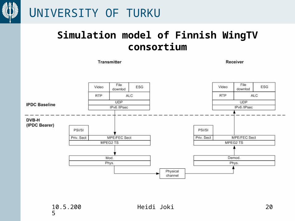
Simulation model of Finnish WingTV consortium

10.5.2005 Heidi Joki 21
UNIVERSITY OF TURKU
Simulation model: motivation• The number of link
layer and physical layer parameters add up to 14400!
• Simulation is the fastest and most economic way of evaluating the impact of different parameters
• Simulation provides an opportunity to test new ways of parsing, decapsulation and decoding
Parameter Options Explanation
Modulation 3 QPSK, 16QAM, 64QAM
FFT-size 3 2K, 4K, 8K
In-depth interleaver 2 On / Off (only for 2K and 4K)
Guard Interval 4 1/4, 1/8, 1/16, 1/32
CC rate 5 1/2, 2/3, 3/4, 5/6, 7/8
MPE-FEC code rate 6 1/2, 2/3, 3/4, 5/6, 7/8, 1
Burst size 4 256, 512, 768, 1024 rows
Burst bit rate 2
Number of combinations
14400
10.5.2005 Heidi Joki 22
UNIVERSITY OF TURKU
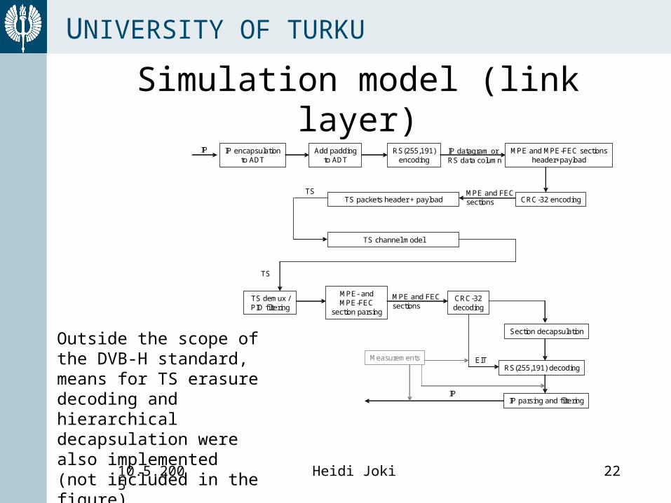
MPE and FECsections
IP encapsulationto ADT
Add paddingto ADT
RS(255,191)encoding
MPE and MPE-FEC sectionsheader+payload
CRC-32 encodingTS packets header + payload
TS demux / PID filtering
MPE- and MPE-FEC
section parsing
CRC-32decoding
Section decapsulation
RS(255,191) decoding
IP parsing and filtering
TS channel model
IP IP datagram or RS data column
MPE and FECsections
TS
TS
EIT
IP
Measurements
Simulation model (link layer)
Outside the scope of the DVB-H standard, means for TS erasure decoding and hierarchical decapsulation were also implemented (not included in the figure).
10.5.2005 Heidi Joki 23
UNIVERSITY OF TURKU
TS erasure decoding
• Except the CRC erasure decoding, means for TS erasure decoding was implemented
• Symbols in the MPE-FEC frame are marked as reliable or unreliable based on the transport_error_indicator in the TS header
• IP datagram lengths not considered

10.5.2005 Heidi Joki 24
UNIVERSITY OF TURKU
The error pattern
MPEG-2Source
DVB-TModulator
ChannelSimulator
NoiseGenerator
DVB-T/H Receiver
MPEG-2 TestSignal
Different DVB-T modes
Hardware channel simulator and noise generator:COST 207 TU channel Fd C/N
LogicAnalyzer
Only the TS error statistics were saved into the file
TS error Data:
100111…Provided by Nokia

10.5.2005 Heidi Joki 25
UNIVERSITY OF TURKU
Simulation parametersThe effect of the following parameters on the MPE-FEC FER can
be examined: • Burst size, i.e. number of rows in MPE-FEC frame• MPE-FEC code rate• Length of IP datagrams• FEC decoder type: TS erasure decoding vs. CRC erasure
decoding• The length of the burst, i.e. the interleaving length
The above mentioned parameters can be simulated with the following physical channel parameters:
• Modulation• Doppler frequency• Convolutional code rate• Channel model: TU6, indoor, pedestrian, etc.

10.5.2005 Heidi Joki 26
UNIVERSITY OF TURKU
Performed simulations• The simulations were
performed with 256- and 1024-row frames
• IP datagram length was 1500 bytes
• Two different simulations were carried out– CRC erasure decoding– TS erasure decoding
• The aim was to compare the two different methods and to study the amount of unnecessary erasures added to the EIT by the CRC decoding
Channel model: TU6
Modulation: 16 QAM
Doppler frequency: 10 Hz
CC rate: ½
Amount of TS packets: 4 193 000
Amount of TS data: 788 MB
IP datagram length: 1500 Bytes
Amount of IP data: 256 rows: 560 MB
1024 rows: 570 MB
MPE-FEC code rate: ¾
Signal to noise ratio: 17 – 20 dB
Amount of MPE-FEC frames:
256 rows: 11 686 frames
1024 rows: 2927 frames
10.5.2005 Heidi Joki 27
UNIVERSITY OF TURKU
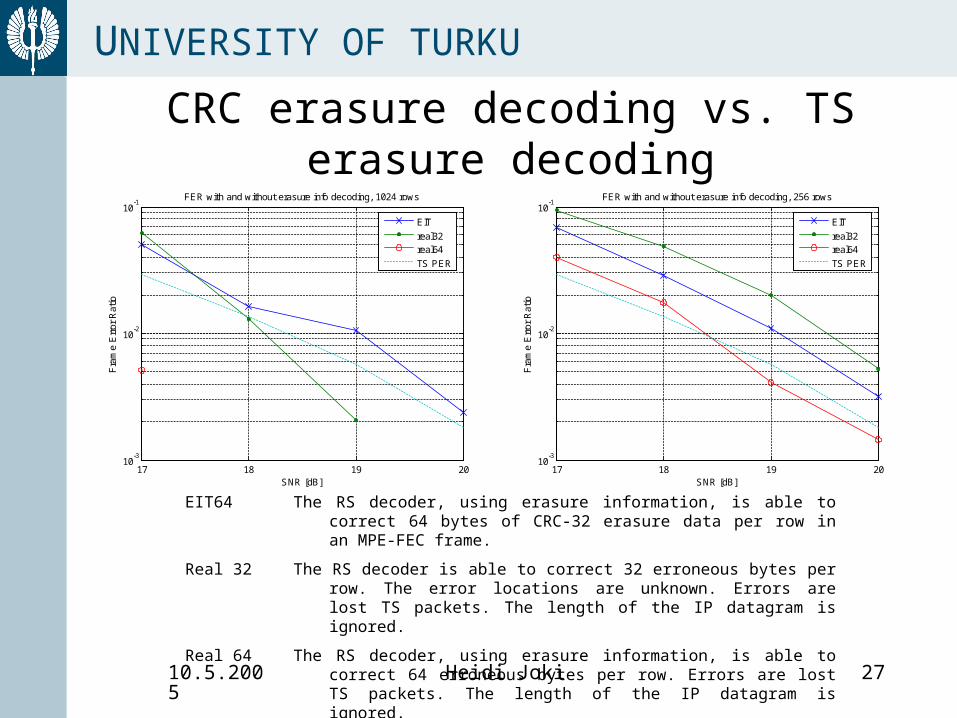
CRC erasure decoding vs. TS erasure decoding
17 18 19 2010
-3
10-2
10-1
FER with and without erasure info decoding, 1024 rows
SNR [dB]
Fra
me
Err
or R
atio
EIT
real32real64
TS PER
17 18 19 2010
-3
10-2
10-1
FER with and without erasure info decoding, 256 rows
SNR [dB]
Fra
me
Err
or R
atio
EIT
real32real64
TS PER
EIT64 The RS decoder, using erasure information, is able to correct 64 bytes of CRC-32 erasure data per row in an MPE-FEC frame.
Real 32 The RS decoder is able to correct 32 erroneous bytes per row. The error locations are unknown. Errors are lost TS packets. The length of the IP datagram is ignored.
Real 64 The RS decoder, using erasure information, is able to correct 64 erroneous bytes per row. Errors are lost TS packets. The length of the IP datagram is ignored.
10.5.2005 Heidi Joki 28
UNIVERSITY OF TURKU
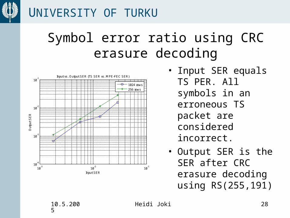
Symbol error ratio using CRC erasure decoding
10-3
10-2
10-1
10-4
10-3
10-2
10-1
Input SER
Out
put
SE
R
Input vs. Output SER (TS SER vs. MPE-FEC SER)
1024 rows
256 rows
• Input SER equals TS PER. All symbols in an erroneous TS packet are considered incorrect.
• Output SER is the SER after CRC erasure decoding using RS(255,191)
10.5.2005 Heidi Joki 29
UNIVERSITY OF TURKU
Result analysis
• CRC-32 erasure decoding adds far too many unnecessary erasures.
• When transmitting 1500B IP datagrams in the smallest frame, the gain of using FEC is almost lost if using erasures based on CRC-32
• TS erasure decoding saves gain in all simulations
• Using a larger MPE-FEC frame gives improvement in gain, when burst length is not considered.

10.5.2005 Heidi Joki 30
UNIVERSITY OF TURKU
Drawbacks of the DVB-H standard
• CRC adds too much erasures into EIT• Lack of protection of the section header• Standard length of IP datagrams or MPE
sections preferable than various length– Achieving constant TS bit rate (or almost
constant for streaming video)– Decapsulation possible, though section
header is lost
• Not 100% certainity of ’reliable’ bytes in MPE-FEC frame has to be considered

10.5.2005 Heidi Joki 31
UNIVERSITY OF TURKU
Suggestions for improvements (without changing the standard)
• TX: Introducing standard length of IP datagrams (e.g. 1 or 2 columns)
• RX: Using TS erasure decoding based on the transport_error_indicator in the TS header
• RX: Using hierarchical decapsulation and decoding if needed (also decapsulate erroneous packets, most of it is probably correct!)
• RX: Using combination of erasure and error decoding

10.5.2005 Heidi Joki 32
UNIVERSITY OF TURKU
The algorithm for hierarchical decapsulation and hierarchical decoding
1. Perform hierarchical decapsulation of TS packets, using the transport_error_indicator when filling in the erasure info table (EIT). Lost data is market with ‘1’, decapsulated but unreliable data is marked with ‘2’ and correct data with ‘0’ in the EIT.
2. Consider all unreliable bytes, marked with ‘1’ or ‘2’ in the EIT, as erasures.
3. If the amount of unreliable bytes is less than 64, use the remaining Hamming distance for error decoding. Perform the erasure (and error) decoding.
4. If the amount of unreliable bytes exceeds 64, consider the bytes marked with ‘2’ in the EIT as reliable and repeat step 3.
• The pure erasure decoding could also fail if some of the bytes marked as reliable are erroneous. In this case step 4 is useful, since it might leave some more Hamming distance for error correction.
• This algorithm can be combined with CRC or TS erasure decoding. TS erasure decoding is recommended.

10.5.2005 Heidi Joki 33
UNIVERSITY OF TURKU
Further work on the simulator• Means for the user to input the simulation parameters should be
implemented. At least the following parameters should be read: – MPE-FEC code rate– The names of the IP data and error pattern files– Burst size and duration– Decoding method to be used; TS erasure or CRC erasure correction
• The TS erasure decoding should be implemented so that IP datagram lengths are taken into account. Also combinations of erasure and error correction should be thought of
• Time-slicing should be implemented • Besides the FER, the output of the simulator should include IP
data along with erasure information, which is used by a potential RS decoder at the application layer
• The simulator should be able to handle a multiplex of many elementary streams
• Hierarchical decapsulation and decoding should be implemented• A symbol based TS error pattern is needed• Functions should be optimized for shortening the simulation time
10.5.2005 Heidi Joki 34
UNIVERSITY OF TURKU
Future work on DVB-H link layer and physical layer
• The impact of the IP datagram lengths and the MPE-FEC code rates should be studied carefully
• The decoding process should be improved and different decoding algorithms should be studied
• Finding the best means of decapsulation and decoding using all received data is already quite a challenge. However, the receiver manufacturers would probably profit from implementing solutions for decoding based on a combination of TS erasure and error correction.
• Proper channel models for indoor and pedestrian use cases should be developed
• Based on the channel models, error patterns based on symbol or bit errors could be developed on TS level

10.5.2005 Heidi Joki 35
UNIVERSITY OF TURKU
Thank You!
Questions?
For more information [email protected]