TYRE - FLEX COUPLINGS TFH / T / TO / RSTspecialproducts.net.au/userfiles/file/6-TYRE-Flex-P4.pdf ·...
4
1 TYRE - FLEX COUPLING The flexible capabilities of the Tyreflex Coupling help to accommodate angular, parallel and axial misalignments. Parallel Misalignment up to 6 mm. Angular Misalignment up to 4 0 . End Float up to 8 mm. Suitable in ambient temp. up to 70 0 C. CUSHIONING SHOCK LOA DS Tyreflex being a torsionally soft coupling protects against vibration, impact loads and heavy shocks in the event of sudden load changes. EA SE OF A SSEMBL Y / DI SA SSEMBL Y Alignment is quickly checked by placing a straight edge across the outside diame ters of the flanges. Installation or replacement of new tyre is achieved without disturbing driver or driven shafts, simply by loosening the clamping screws, placing a new tyre between the flanges and clamping rings and then tightening the clamping screws. FEA TURES Tyre-flex type TFH consists of four parts namely Hub, Clamping ring, Flange & Tyre clamped with a set of screws and washers. These are reversible which permit arranging them in any position FF, HH, HF as shown. Low inventory is the important feature of this type. DIMENSIONAL DAT A J is the wrench clearance to allow for tightening and loosening the bush on the shaft. The use of a shortened wrench will allow this dimension to be reduced. For Torque & Power rating refer page 2. Weights & M.I.. are at without bores. For detail information about Taper Bush bore, please refer Taper Bush catalogue. TYPE TFH / T / TO / RST TYRE - FLEX COUPLINGS TYPE TFH Weight Moment kg of inertia (WR 2 ) kgm 2 Inch Metric TFH 7 1610 1 5/8 42 197 144 25 76 38 69 17 19 6.8 0.018 TFH 8 2012 2 50 210 167 32 96 42 85 17 21 9.1 0.036 TFH 9 2517 2 1/2 60 235 188 45 110 48 101 19 11 13.2 0.064 TFH 10 2517 2 1/2 60 254 216 45 125 48 102 19 12 18.7 0.110 TFH 11 3020 3 75 279 233 51 140 55 108 22 6 23.5 0.160 TFH 12 3020 3 75 314 264 51 152 55 111 25 9 34.1 0.280 H F M F G J E Max. Bore Size Bush No Ø A Ø C E Ø D J F G M
Transcript of TYRE - FLEX COUPLINGS TFH / T / TO / RSTspecialproducts.net.au/userfiles/file/6-TYRE-Flex-P4.pdf ·...
1
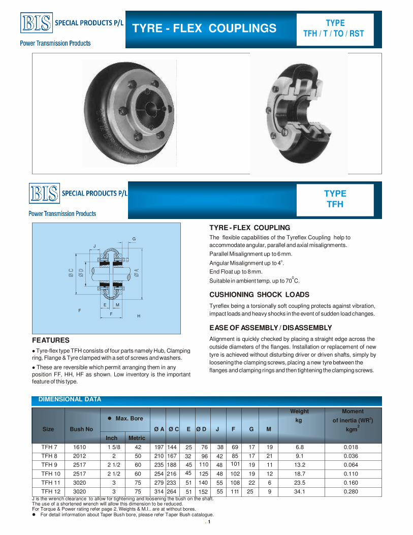
TYRE - FLEX COUPLING
The flexible capabilities of the Tyreflex Coupling help to
accommodate angular, parallel and axial misalignments.
Parallel Misalignment up to 6 mm.
Angular Misalignment up to 40.
End Float up to 8 mm.
Suitable in ambient temp. up to 700C.
CUSHIONING SHOCK LOADS
Tyreflex being a torsionally soft coupling protects against vibration,
impact loads and heavy shocks in the event of sudden load changes.
EASE OF ASSEMBLY / DISASSEMBLY
Alignment is quickly checked by placing a straight edge across the
outside diameters of the flanges. Installation or replacement of new
tyre is achieved without disturbing driver or driven shafts, simply by
loosening the clamping screws, placing a new tyre between the
flanges and clamping rings and then tightening the clamping screws.
FEATURES
� Tyre-flex type TFH consists of four parts namely Hub, Clamping
ring, Flange & Tyre clamped with a set of screws and washers.
� These are reversible which permit arranging them in any
position FF, HH, HF as shown. Low inventory is the important
feature of this type.
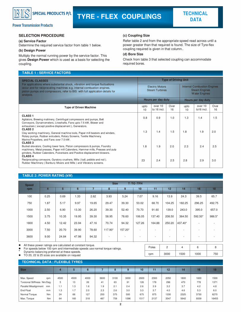
DIMENSIONAL DATA
J is the wrench clearance to allow for tightening and loosening the bush on the shaft. The use of a shortened wrench will allow this dimension to be reduced. For Torque & Power rating refer page 2. Weights & M.I.. are at without bores. � For detail information about Taper Bush bore, please refer Taper Bush catalogue.
TYPE
TFH / T / TO / RST TYRE - FLEX COUPLINGS
TYPE
TFH
Weight Moment
kg of inertia (WR2)
kgm2
Inch Metric
TFH 7 1610 1 5/8 42 197 144 25 76 38 69 17 19 6.8 0.018
TFH 8 2012 2 50 210 167 32 96 42 85 17 21 9.1 0.036
TFH 9 2517 2 1/2 60 235 188 45 110 48 101 19 11 13.2 0.064
TFH 10 2517 2 1/2 60 254 216 45 125 48 102 19 12 18.7 0.110
TFH 11 3020 3 75 279 233 51 140 55 108 22 6 23.5 0.160
TFH 12 3020 3 75 314 264 51 152 55 111 25 9 34.1 0.280
H
F
M
F
G
J
E
� Max. Bore
Size Bush No Ø A Ø C E Ø D J F G M
0.8 0.9 1.0 1.3 1.4 1.5
1.3 1.4 1.5 1.8 1.9 2.0
1.8 1.9 2.0 2.3 2.5
2.3 2.4 2.5 2.8 2.9 3.0
2
SELECTION PROCEDURE
(a) Service Factor
Determine the required service factor from table 1 below.
(b) Design Power
Multiply the normal running power by the service factor. This
gives Design Power which is used as a basis for selecting the
coupling.
(c) Coupling Size
Refer table 2 and from the appropriate speed read across until a
power greater than that required is found. The size of Tyre-flex coupling required is given in that column..
(d) Bore Size
Check from table 3 that selected coupling can accommodate
required bores.
TABLE 1 : SERVICE FACTORS
TABLE 2: POWER RATING (kW)
TECHNICAL DATA : FLEXIBLE TYRES
Hours per day duty
Type of Driven Machine upto
10
over 10
to 16 incl. Over
16
over 10
to16 incl. Over
16
CLASS 1
Agitators, Brewing mahinery, Centrifugal compressors and pumps, Belt
Conveyors, Dynamometers, Lineshafts, Fans upto 7.5 kW, Blower and
exhausters ( except positive displacement ), Generators.
CLASS 2
Clay working machinery, General machine tools, Paper mill beaters and winders,
Rotary pumps, Rubber extruders, Rotary Screens, Textile Machinery,
Marine Propellers, and Fans over 7.5 kW.
CLASS 3
Bucket elevators, Cooling tower fans, Piston compressors & pumps, Foundry
machinery, Metal presses, Paper mill Calenders, Hammer mills, Presses and pulp
grinders, Rubber Calenders, Pulverisers and Positive displacement blowers.
CLASS 4 Reciprocating conveyors, Gyratory crushers, Mills ( ball, pebble and rod ).
Rubber Machinery ( Banbury Mixers and Mills ) and Vibratory screens.
Speed
rpm 4 5 6 7 8 9 10 11 12 14 16 18
100 0.25 0.69 1.33 2.62 3.93 5.24 7.07 9.16 13.9 24.3 39.5 65.7
750 1.87 5.17 9.97 19.65 29.47 39.30 53.02 68.70 104.25 182.25 296.25 492.75
1000 2.50 6.90 13.30 26.20 39.30 52.40 70.70 91.60 139.0 243.0 395.0 657.0
1500 3.75 10.35 19.95 39.30 58.95 78.60 106.05 137.40 208.50 364.50 592.50* 986.5*
1800 4.50 12.42 23.94 47.16 70.74 94.32 127.26 164.88 250.20 437.40* - -
3000 7.50 20.70 39.90 78.60 117.90* 157.20* - - - - - -
3600 9.00 24.84 47.98 94.32 - - - - - - - -
Size T /TO /TFH
� All these power ratings are calculated at constant torque. � For speeds below 100 rpm and intermediate speeds use normal torque ratings. * Dynamic balancing preferred at these speeds. � TO 20, 22 & 25 sizes are available on request
TECHNICAL
DATA TYRE - FLEX COUPLINGS
Poles 2 4 6 8
rpm 3000 1500 1000 750
Size 4 5 6 7 8 9 10 11 12 14 16 18
Max. Speed rpm 4500 4500 4000 3600 3100 3000 2600 2300 2050 1800 1600 1500
Torsional Stiffness Nm/Deg. 5 13 26 41 63 91 126 178 296 470 778 1371
Parallel Misalignment mm 1.1 1.3 1.6 1.9 2.1 2.4 2.6 2.9 3.2 3.7 4.2 4.8
End Float mm 1.3 1.7 2.0 2.3 2.6 3.0 3.3 3.7 4.0 4.6 5.3 6.0
Normal Torque Nm 24 66 127 250 375 500 675 875 1330 2325 3730 6270
Max. Torque Nm 64 160 318 487 759 1096 1517 2137 3547 5642 9339 16455
SPECIAL CLASSES
For applications where substantial shock, vibration and torque fluctuations
occur and for reciprocating machines e.g. internal combustion engines,
piston pumps and compressors, refer to BIS with full application details for analysis.
Type of Driving Unit
Electric Motors
Steam Turbines
Internal Combustion Engines
Steam Engines
Water Engines
Hours per day duty
upto
10
2.4
3
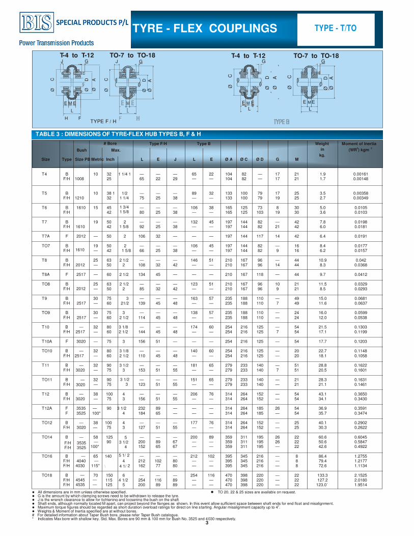
TABLE 3 : DIMENSIONS OF TYRE-FLEX HUB TYPES B, F & H
TYPE - T/TO TYRE - FLEX COUPLINGS
T-4 to T-12 TO-7 to TO-18
E M E E M E
G
L L
Ø C
Ø C
Ø D
Ø D
Ø A
Ø A
G
TYPE F / H H F
T-4 to T-12 TO-7 to TO-18 J J G G
E M E
Ø C
Ø
C
Ø D
Ø D
Ø A
Ø A
L
Size Type Size PB Metric Inch L E J L E Ø A Ø C Ø D G M
T4 B 10 32 1 1/4 — — — 65 22 104 82 — 17 21 1.9 0.00161 F/H 1008 25
1 65 22 29 — — 104 82 — 17 21 1.7 0.00148
T5 B 10 38 1 1/2 — — — 89 32 133 100 79 17 25 3.5 0.00358 F/H 1210 32 1 1/4 75 25 38 — — 133 100 79 19 25 2.7 0.00349
T6 B 15 45 1 3/4 — — — 106 38 165 125 73 8 30 5.0 0.0105 F/H
1610
42 1 5/8 80 25 38 — — 165 125 103 19 30 3.6 0.0103
T7 B 19 50 2 — — — 132 45 197 144 82 — 42 7.8 0.0198 F/H 1610 42 1 5/8 92 25 38 — — 197 144 82 21 42 6.0 0.0181
T7A F 2012 — 50 2 106 32 — — — 197 144 117 14 42 6.4 0.0191
TO7 B 19 50 2
— — — 106 45 197 144 82 — 16 8.4 0.0177 F/H 1610 — 42 1 5/8 66 25 38 — — 197 144 82 9 16 6.2 0.0157
T8 B 25 63 2 1/2 — — — 146 51 210 167 96 — 44 10.9 0.042 F/H 2012 — 50 2 108 32 42 — — 210 167 96 14 44 8.3 0.0368
T8A F 2517 — 60 2 1/2 134 45 — — — 210 167 118 — 44 9.7 0.0412
TO8 B 25 63 2 1/2 — — — 123 51 210 167 96 10 21 11.5 0.0329 F/H 2012 — 50 2 85 32 42 — — 210 167 96 9 21 8.5 0.0293
T9 B 30 75 3 — — — 163 57 235 188 110 — 49 15.0 0.0681
F/H 2517 — 60 21/2 139 45 48 — — 235 188 110 7 49 11.6 0.0637
TO9 B 30 75 3 — — — 138 57 235 188 110 — 24 16.0 0.0599 F/H 2517 — 60 2 1/2 114 45 48 — — 235 188 110 — 24 12.0 0.0538
T10 B — 32 80 3 1/8 — — — 174 60 254 216 125 — 54 21.5 0.1303 F/H 2517 — 60 2 1/2 144 45 48 — — 254 216 125 7 54 17.1 0.1199
T10A F 3020 — 75 3 156 51 — — — 254 216 125 — 54 17.7 0.1203
TO10 B — 32 80 3 1/8 — — — 140 60 254 216 125 — 20 22.7 0.1148 F/H 2517 — 60 2 1/2 110 45 48 — — 254 216 125 — 20 18.1 0.1058
T11 B — 32 90 3 1/2 — — — 181 65 279 233 140 — 51 28.8 0.1622 F/H 3020 — 75 3 153 51 55 — — 279 233 140 7 51 20.5 0.1601
TO11 B — 32 90 3 1/2 — — — 151 65 279 233 140 — 21 28.3 0.1631 F/H 3020 — 75 3 123 51 55 — — 279 233 140 — 21 21.1 0.1461
T12 B — 38 100 4 — — — 206 76 314 264 152 — 54 43.1 0.3650 F/H 3020 — 75 3 156 51 55 — — 314 264 152 — 54 34.1 0.3430
T12A F 3535 — 90 3 1/2 232 89 — — — 314 264 185 26 54 36.9 0.3591 F 3525 100* 4 184 65 — — — 314 264 185 — 54 35.7 0.3474
TO12 B — 38 100 4 — — — 177 76 314 264 152 — 25 40.1 0.2902 F/H 3020 — 75 3 127 51 55 — — 314 264 152 — 25 30.3 0.2622
TO14 B — 58 125 5 — — — 200 89 359 311 195 26 22 60.6 0.6045
F/H 3535 90 3 1/2 200 89 67 — — 359 311 195 26 22 50.6 0.5847
F/H 3525 —
100* 4 152 65 67 — — 359 311 195 — 22 42.6 0.4922
TO16 B — 65 140 5 1/ 2 — — — 212 102 395 345 216 — 8 86.4 1.2755 F/H 4040 —
4 212 102 80 — — 395 345 216 — 8 79.4 1.2177 F/H 4030 115* \ 4 1/ 2 162 77 80 — — 395 345 216 — 8 72.6 1.1134
TO18 B — 70 150 6 — — — 254 116 470 398 220 — 22 133.3 2.1525 F/H 4545 — 115 4 1/2 254 116 89 — — 470 398 220 — 22 127.2 2.0180 F/H 4535 — 125 5 200 89 89 — — 470 398 220 — 22 123.0` 1.9514
Moment of Inertia
(WR2) kgm
2
Weight
in
kg.
Type B Type F/H
Max. Bush
# Bore
� All dimensions are in mm unless otherwise specified. � G is the amount by which clamping screws need to be withdrawn to release the tyre. � J is the wrench clearance to allow for tightening and loosening the bush on the shaft.� Shaft ends, although normally located M apart, can project beyond the flanges as shown. In this event allow sufficient space between shaft ends for end float and misalignment. � Maximum torque figures should be regarded as short duration overload ratings for direct on line starting. Angular misalignment capacity up to 4
0.
� Weights & Moment of Inertia specified are at without bores. # For detailed information about Taper Bush bore, please refer T aper Bush catalogue.* Indicates Max bore with shallow key. Std. Max. Bores are 90 mm & 100 mm for Bush No. 3525 and 4030 respectively.
� TO 20, 22 & 25 sizes are available on request.
4
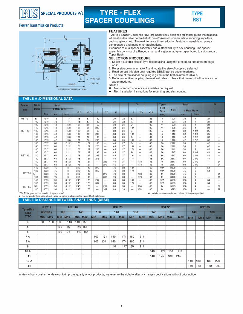
FEATURES Tyre-flex Spacer Couplings RST are specifically designed for motor-pump installations, where it is desirable not to disturb drive/driven equipment while servicing impellers, packing glands, etc. The maintenance time-reduction feature is valuable on pumps, compressors and many other applications. It comprises of a spacer assembly and a standard Tyre-flex coupling. The spacer assembly consists of a flanged shaft and a spacer adapter taper bored to suit standard Taper Bush.
SELECTION PROCEDURE 1. Select a suitable size of Tyre-flex coupling using the procedure and data on page
no.2. 2. Refer size column in table A and locate the size of coupling selected. 3. Read across this size until required DBSE can be accommodated.4. The size of the spacer coupling is given in the first column of table A. 5. Refer respective coupling dimensional table to check that the required bores can be accommodated. Notes : � Non-standard spacers are available on request. � Ref. installation instructions for mounting and dismounting.
TABLE A :DIMENSIONAL DATA
TABLE B: DISTANCE BETWEEN SHAFT ENDS (DBSE)
In view of our constant endeavour to improve quality of our products, we reserve the right to alter or change specifications without prior notice.
RST12 RST 16 RST 25 RST 30 RST 35
TYPE
RST
TYRE - FLEX SPACER COUPLINGS
M
DISTANCE BETWEEN SHAFT ENDS
D B S E
TYRE-FLEX
COUPLING
Ø C
Ø D
F
ØB
J
Ø C Ø D T TO F J T TO Ø B T TO
Tyre--
Flex
Size
T/TO
ME S
# Max. Bore
RST 35 140
RST 30 140
Bush Bush
Tyre-flex
Size
T/TO
* T4 ‘B’ flange must be used to fit spacer shaft. # For detailed information about Taper Bush bore, please refer T aper Bush catalogue.
Spacer Nom
Size DBSE # Max. Bore Size
Size mm Inch mm Inch
RST12 80 1210 32 1 1/4 118 83 130 — 25 22 57 — 25 4 1008 25 1 21 —
100 1210 32 1 1/4 118 83 150 — 25 22 77 — 25 4 1008 25 1 21 —
100 1615 42 1 5/8 127 80 163 — 38 24 94 — 32 4* 1008 25 1 21 —
140 1615 42 1 5/8 127 80 203 — 38 24 134 — 32 4* 1008 25 1 21 —
RST 16 100 1615 42 1 5/8 127 80 166 — 38 24 94 — 32 5 1210 32 1 1/4 25 —
140 1615 42 1 5/8 127 80 206 — 38 24 134 — 32 5 1210 32 1 1/4 25 —
100 1615 42 1 5/8 127 80 166 — 38 24 94 — 32 6 1610 42 1 5/8 30 —
140 1615 42 1 5/8 127 80 206 — 38 24 134 — 32 6 1610 42 1 5/8 30 —
100 2517 60 2 1/2 178 127 180 — 45 27 94 — 48 7A 2012 50 2 42 —
140 2517 60 2 1/2 178 127 220 — 45 27 134 — 48 7A 2012 50 2 42 —
180 2517 60 2 1/2 178 127 260 — 45 27 174 — 48 7A 2012 50 2 42 —
100 2517 60 2 1/2 178 127 193 — 45 27 94 — 48 8A 2517 60 2 1/2 44 —
RST 25 140 2517 60 2 1/2 178 127 233 — 45 27 134 — 48 8A 2517 60 2 1/2 44 —
180 2517 60 2 1/2 178 127 273 — 45 27 174 — 48 8A 2517 60 2 1/2 44 —
140 2517 60 2 1/2 178 127 — 233 45 27 — 134 48 9 2517 60 2 1/2 — 24
180 2517 60 2 1/2 178 127 — 273 45 27 — 174 48 9 2517 60 2 1/2 — 24
140 3030 75 3 216 146 270 — 76 33 134 — 60 10A 3020 75 3 54 —
180 3030 75 3 216 146 310 — 76 33 174 — 60 10A 3020 75 3 54 —
3030 75 3 216 146 — 270 76 33 — 134 60 11 3020 75 3 — 21
180 3030 75 3 216 146 — 310 76 33 — 174 60 11 3020 75 3 — 21
140 3535 90 3 1/2 248 178 297 — 89 33 134 — 80 12A 3525 100 4 54 —
180 3535 90 3 1/2 248 178 337 — 89 33 174 — 80 12A 3525 100 4 54 —
3535 90 3 1/2 248 178 — 297 89 33 — 134 80 14 3525 100 4 — 22
180 3535 90 3 1/2 248 178 — 337 89 33 — 174 80 14 3525 100 4 — 22
80(100 ) 100 140 100 140 180 140 180 140 180
Min Max Min Max Min Max Min Max Min Max Min Max Min Max Min Max Min Max Min Max
4 80 100 100 113 140 153
5 100 116 140 156
6 100 124 140 164
7 A 100 131 140 171 180 211
8 A 100 134 140 174 180 214
9 140 177 180 217
10 A 140 179 180 219
11 140 175 180 215
12 A 140 180 180 220
14 140 163 180 203
� All dimensions are in mm unless otherwise specified.
E S