Type T205B Balanced Tank Blanketing Regulator · Fisher® tank blanketing regulators must be...
12
Type T205B D103750X012 Instruction Manual April 2014 www.fisherregulators.com Type T205B Balanced Tank Blanketing Regulator ! WARNING Failure to follow these instructions or to properly install and maintain this equipment could result in an explosion, fire and/or chemical contamination causing property damage and personal injury or death. Fisher ® tank blanketing regulators must be installed, operated and maintained in accordance with federal, state and local codes, rules and regulations and Emerson Process Management Regulator Technologies, Inc. (Regulator Technologies) instructions. If the regulator discharges process fluid or a leak develops in the system, service to the unit may be required. Failure to correct trouble could result in a hazardous condition. Call a qualified service person to service the unit. Installation, operation and maintenance procedures performed by unqualified person may result in improper adjustment and unsafe operation. Either condition may result in equipment damage or personal injury. Only a qualified person must install or service the Type T205B tank blanketing regulator. Introduction Scope of the Manual This Instruction Manual provides instruction for installation, startup, maintenance and parts ordering information for Type T205B tank blanketing regulator. Product Description Type T205B balanced tank blanketing regulator (Figure 1) is a direct-operated regulator with fully balanced plug design to reduce inlet pressure sensitivity and with large diaphragm to accurately control tank pressure at low pressure settings on tank blanketing systems. The regulator prevents a stored liquid from vaporizing into the atmosphere, reduces liquid combustibility and prevents oxidation or contamination of the liquid by reducing its exposure to air. Type T205B maintains a slightly positive pressure and thereby reduces the possibility of tank wall collapse during pump out operation. Contents Introduction .................................................................. 1 Specifications .............................................................. 2 Principle of Operation .................................................. 3 Installation ................................................................... 4 Startup ......................................................................... 6 Adjustment................................................................... 6 Shutdown..................................................................... 7 Maintenance ................................................................ 7 Parts List.................................................................... 11 Figure 1. Type T205B Tank Blanketing Regulator
Transcript of Type T205B Balanced Tank Blanketing Regulator · Fisher® tank blanketing regulators must be...

Type T205B
D10
3750
X01
2
Instruction Manual
April 2014
www.fisherregulators.com
Type T205B Balanced Tank Blanketing Regulator
! WARNING
Failure to follow these instructions or to properly install and maintain this equipment could result in an explosion, fi re and/or chemical contamination causing property damage and personal injury or death.Fisher® tank blanketing regulators must be installed, operated and maintained in accordance with federal, state and local codes, rules and regulations and Emerson Process Management Regulator Technologies, Inc. (Regulator Technologies) instructions.If the regulator discharges process fl uid or a leak develops in the system, service to the unit may be required. Failure to correct trouble could result in a hazardous condition.Call a qualifi ed service person to service the unit. Installation, operation and maintenance procedures performed by unqualifi ed person may result in improper adjustment and unsafe operation. Either condition may result in equipment damage
or personal injury. Only a qualifi ed person must install or service the Type T205B tank blanketing regulator.
IntroductionScope of the ManualThis Instruction Manual provides instruction for installation, startup, maintenance and parts ordering information for Type T205B tank blanketing regulator.
Product DescriptionType T205B balanced tank blanketing regulator (Figure 1) is a direct-operated regulator with fully balanced plug design to reduce inlet pressure sensitivity and with large diaphragm to accurately control tank pressure at low pressure settings on tank blanketing systems. The regulator prevents a stored liquid from vaporizing into the atmosphere, reduces liquid combustibility and prevents oxidation or contamination of the liquid by reducing its exposure to air. Type T205B maintains a slightly positive pressure and thereby reduces the possibility of tank wall collapse during pump out operation.
ContentsIntroduction ..................................................................1Specifications ..............................................................2Principle of Operation ..................................................3Installation ...................................................................4Startup .........................................................................6Adjustment...................................................................6Shutdown.....................................................................7Maintenance ................................................................7Parts List.................................................................... 11
Figure 1. Type T205B Tank Blanketing Regulator

Type T205B
2
SpecificationsThis section lists the specifications of the Type T205B Tank Blanketing Regulator. Factory specification, such as maximum temperature, maximum inlet and outlet pressures, spring range and seat or orifice size are stamped on the nameplate fastened on the regulator at the factory.
Body Sizes and End Connection StylesSee Table 1
Maximum Allowable Inlet Pressure(1)
See Table 1Maximum Operating Inlet Pressure(1)
Gray cast iron: 150 psig / 10.3 barWCC Carbon steel or CF8M/CF3M Stainless steel: 200 psig / 13.8 bar
Maximum Outlet (Casing) Pressure(1) Gray cast iron: 35 psig / 2.4 barWCC Carbon steel or CF8M/CF3M Stainless steel: 75 psig / 5.2 bar
Maximum Emergency Outlet Pressure to Avoid Internal Parts Damage(1)
With Nitrile (NBR) or Fluorocarbon (FKM) diaphragm: 35 psig / 2.4 barWith Fluorinated Ethylene Propylene (FEP) diaphragm: 10 psig / 0.69 bar
Outlet (Control) Pressure Range(1)
See Table 2Shutoff Classification per ANSI/FCI 70-3-2004
Class VI (Soft Seat)
Pressure Registration External
Material Temperature Capabilities(1)(2)
Elastomer Parts Nitrile (NBR): -40 to 180°F / -40 to 82°C Fluorinated Ethylene Propylene (FEP): -20 to 180°F / -29 to 82°C Fluorocarbon (FKM): 40 to 300°F / 4 to 149°C Ethylene Propylene Diene (EPDM): -20 to 225°F / -29 to 107°C Perfluoroelastomer (FFKM): 0 to 300°F / -18 to 149°CBody Materials Gray cast iron: -20 to 300°F / -29 to 149°C WCC Carbon steel: -20 to 300°F / -29 to 149°C CF8M/CF3M Stainless steel: -40 to 300°F / -40 to 149°C
Spring Case Vent Connection1/4 NPT
Diaphragm Case Control Line Connection1/2 NPT
Approximate Weight17.7 pounds / 8 kg
1. The pressure/temperature limits in this Instruction Manual and any applicable standard or code limitation should not be exceeded.2. See Table 4 for operating temperature ranges for available trim combinations.
Table 2. Outlet (Control) Pressure Ranges and Spring Information
OUTLET (CONTROL) PRESSURE RANGE SPRING
PART NUMBERSPRING COLOR
SPRING WIRE DIAMETER SPRING FREE LENGTH
Inch w.c. mbar Inch mm Inch mm1 to 2.5(1)(2) 2.5 to 6.2(1)(2) 1B558527052 Orange 0.072 1.8 3.25 82.62.5 to 7(2) 6.2 to 17(2) 1B653827052 Red 0.085 2.2 3.63 92.27 to 16 17 to 40 1B653927022 Unpainted 0.105 2.7 3.75 95.2
0.5 to 1.2 psig 34 to 83 1B537027052 Yellow 0.114 2.9 4.31 1091.2 to 2.5 psig 83 to 172 1B537127022 Green 0.156 4.0 4.06 1032.5 to 4.5 psig 0.17 to 0.31 bar 1B537227022 Light Blue 0.187 4.8 3.94 1004.5 to 7 psig 0.31 to 0.48 bar 1B537327052 Black 0.218 5.5 3.98 101
1. Do not use Fluorocarbon (FKM) diaphragm with this spring at diaphragm temperatures lower than 60°F / 16°C.2. To achieve the published outlet pressure range the spring case must be installed pointing down.
BODY SIZE BODY MATERIAL END CONNECTION STYLE(1)
MAXIMUM ALLOWABLE INLET PRESSUREInch DN psig bar
3/4 or 1 20 or 25
Gray cast iron NPT 150 10.3
WCC Carbon steel NPT, CL150 RF, CL300 RF or
PN 16/25/40 RF200 13.8CF8M/CF3M
Stainless steel(2)
1. All flanges are welded. Weld-on flange dimension is 14 inches / 356 mm face-to-face.2. Pipe nipples and flanges are 316 Stainless steel for flanged body assemblies.
Table 1. Body Sizes, End Connection Styles and Maximum Allowable Inlet Pressures
Type T205B
3
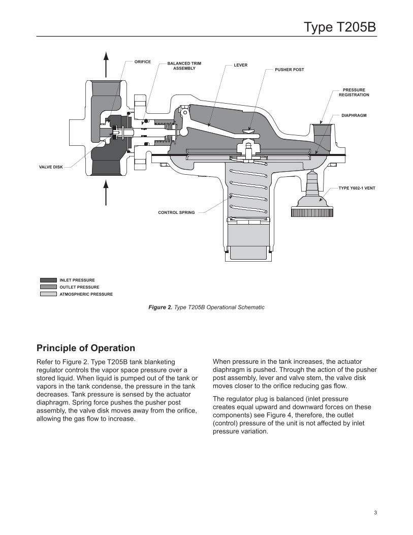
When pressure in the tank increases, the actuator diaphragm is pushed. Through the action of the pusher post assembly, lever and valve stem, the valve disk moves closer to the orifice reducing gas flow.
The regulator plug is balanced (inlet pressure creates equal upward and downward forces on these components) see Figure 4, therefore, the outlet (control) pressure of the unit is not affected by inlet pressure variation.
Principle of OperationRefer to Figure 2. Type T205B tank blanketing regulator controls the vapor space pressure over a stored liquid. When liquid is pumped out of the tank or vapors in the tank condense, the pressure in the tank decreases. Tank pressure is sensed by the actuator diaphragm. Spring force pushes the pusher post assembly, the valve disk moves away from the orifice, allowing the gas flow to increase.
Type T205B Tank Blanketing Regulator
MXXXX
November 2012Type T205B
INLET PRESSUREOUTLET PRESSUREATMOSPHERIC PRESSURE
ORIFICE BALANCED TRIM ASSEMBLY
VALVE DISK
CONTROL SPRING
LEVERPUSHER POST
PRESSURE REGISTRATION
DIAPHRAGM
TYPE Y602-1 VENT
Figure 2. Type T205B Operational Schematic
HORIZONTAL PIPELINE
VENT POINTED DOWN
DOWNSTREAM CONTROL LINE
INLET PRESSUREOUTLET PRESSUREATMOSPHERIC PRESSURE
LOADING PRESSURE

Type T205B
4
Figure 3. Type T205B Actuator Casing Drainage
Installation
! WARNING
Personal injury, property damage, equipment damage or leakage due to escaping gas or bursting of pressure-containing parts may result if this regulator is overpressured or installed where service conditions could exceed the limits given in the Specifications section or where conditions exceed any ratings of the adjacent piping or piping connections. Refer to Overpressure Protection section for recommendations on how to prevent service conditions from exceeding those limits.To avoid such injury or damage, provide pressure-relieving or pressure-limiting devices (as required by the appropriate code, regulation or standard) to prevent service conditions from exceeding limits.Additionally, physical damage to the regulator could cause personal injury or property damage due to escaping gas. To avoid such injury or damage, install the regulator in a safe location.
Note
If the regulator is shipped mounted on another unit, install that unit according to the appropriate instruction manual.
1. Only personnel qualified through training and experience shall install, operate and maintain a regulator. For a regulator that is shipped separately, make sure there is no damage to or debris in the regulator. Also ensure that all tubing and piping are clean and unobstructed.
2. The regulator may be installed in any position as long as the flow through the body is in the direction indicated by the arrow on the body. For proper operation to achieve the published capacities at low setpoint, the spring case barrel should be installed pointing downward as shown in Figure 1. For complete actuator drainage, the regulator should be installed as shown in Figure 3. If continuous operation of the system is required during inspection or maintenance, install a three-valve bypass around the regulator.
HORIZONTAL PIPELINE
VENT POINTED DOWN
DOWNSTREAM CONTROL LINE
INLET PRESSUREOUTLET PRESSUREATMOSPHERIC PRESSURE
LOADING PRESSURE

Type T205B
5
Figure 4. Balanced Trim Assembly
! WARNING
A regulator may vent some gas to the atmosphere. In hazardous or fl ammable gas service, vented gas may accumulate and cause personal injury, death or property damage due to fi re or explosion. Vent a regulator in hazardous gas service to a remote, safe location away from air intakes or any hazardous area. The vent line or stack opening must be protected against condensation or clogging.
3. To keep the vent assembly (key 26, Figure 6) from being plugged or the spring case (key 3) from collecting moisture, corrosive chemicals or other foreign material, point the vent down or otherwise protect it. The diaphragm casing (key 4) may be rotated in order to obtain desired positioning.
4. To remotely vent the regulator, remove the vent (key 26, Figure 6) and install obstruction-free tubing or piping into the 1/4 NPT vent tapping. Provide protection on a remote vent by installing a screened vent cap into the remote end of the vent pipe.
5. The Type T205B requires a downstream control line. Be sure to install the control line before putting the regulator into operation. Make the control line as short and straight as possible and do not install it in a location where fl ow may be turbulent. Restrictions in the control line can prevent proper pressure registration. When using a hand valve, it should be a full fl ow valve, such as a full port ball valve. Install the control line sloping downward toward the tank to prevent condensation buildup and avoid low points (or traps) that could catch liquid. The sensing line must enter the tank above the liquid level at a point that senses the vapor space pressure and is free from turbulence associated with tank nozzles or vents. The control line pipe should be at least 1/2-inch / 13 mm in diameter and increase 1 pipe size for every 10 feet / 3.05 m of control line, with setpoints less than 5-inches w.c. / 12 mbar.
6. An upstream shutoff valve is recommended to simplify maintenance to the regulator. It is advisable to install a pressure gauge between the upstream shutoff valve and the blanketing valve.
BIAS SPRING SEAT (KEY 40)BIAS SPRING (KEY 39)
GUIDE INSERT (KEY 18)
DISK (KEY 13)
STEM (KEY 14)INSERT SEAL O-RING (KEY 12)

Type T205B
6
Startup1. Open shutoff valves between the tank blanketing
regulator and the tank (both sensing and outlet).
2. Slowly open the supply line shutoff valve (to the blanketing valve) and leave it fully open.
3. Monitor the tank vapor space pressure.
Adjustment
! WARNING
To avoid personal injury, property damage or equipment damage caused by bursting of pressure containing parts or explosion of accumulated gas, never adjust the control spring to produce an outlet pressure higher than the upper limit of the outlet pressure range (see Table 2) for that particular spring. If the desired outlet pressure is not within the range of the control spring, install a spring of the proper range according to the Diaphragm and Spring Case Area section of the maintenance procedure.
Adjust the regulator outlet (control) pressure setting to meet the requirements of the specific application. With a spring-loaded regulator, the pressure setting may be adjusted to a value within the spring range shown in Table 2. To adjust the pressure setting, perform the following steps (key numbers are referenced in Figure 6):
For internal flat circular adjusting screw1. Remove the closing cap (key 22).
2. Use a 1-inch / 25 mm hex rod or flat screwdriver to turn the adjusting screw (key 35) either clockwise to increase outlet pressure or counterclockwise to decrease outlet pressure. Always use pressure gauge to monitor the tank blanketing gas pressure when making adjustments.
3. After making the adjustment, replace the closing cap gasket (key 25) and install the closing cap (key 22).
For external square head adjusting screw1. Loosen the locknut (key 20).
2. Turn the adjusting screw (key 35) either clockwise to increase outlet pressure or counterclockwise to decrease outlet pressure. Always use pressure
Overpressure Protection
! WARNING
Personal injury, equipment damage or leakage due to escaping accumulated gas or bursting of pressure-containing parts may result if this regulator is: • Overpressured • Used with incompatible process fluid • Installed where service conditions
could exceed the limits given in the Specifications section and on the appropriate nameplate
• Where conditions exceed any ratings of adjacent piping or piping connections
To avoid such injury or damage, provide pressure-relieving or pressure-limiting devices to prevent service conditions from exceeding those limits.
Type T205B regulators have an outlet pressure rating lower than the inlet pressure rating. The recommended pressure limitations are stamped on the regulator nameplate. Some type of overpressure protection is needed if the actual inlet pressure can exceed the maximum operating outlet pressure rating. Common methods of external overpressure protection include relief valves, monitoring regulators, shut-off devices and series regulation. Overpressuring any portion of the regulators beyond the limits in the Specifications section may cause leakage, damage to regulator parts or personal injury due to bursting of pressure-containing parts.If the regulator is exposed to an overpressure condition, it should be inspected for any damage that may have occurred. Regulator operation below the limits specified in the Specifications section and regulator nameplate does not preclude the possibility of damage from external sources or from debris in the pipeline.
Startup, Adjustment and ShutdownNote
The Specifications section and Table 1 provide the maximum pressure capabilities for each regulator construction. Use pressure gauges to monitor inlet pressure and outlet pressure during startup and adjustment procedures.
Type T205B
7
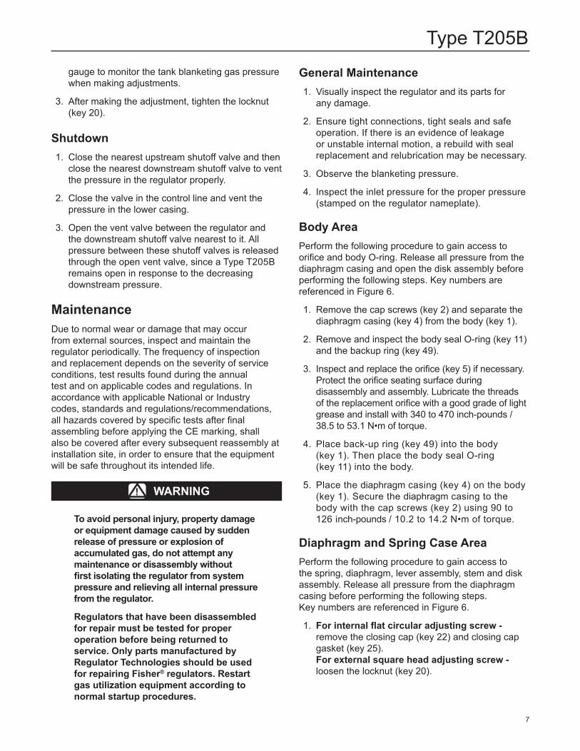
gauge to monitor the tank blanketing gas pressure when making adjustments.
3. After making the adjustment, tighten the locknut (key 20).
Shutdown1. Close the nearest upstream shutoff valve and then
close the nearest downstream shutoff valve to vent the pressure in the regulator properly.
2. Close the valve in the control line and vent the pressure in the lower casing.
3. Open the vent valve between the regulator and the downstream shutoff valve nearest to it. All pressure between these shutoff valves is released through the open vent valve, since a Type T205B remains open in response to the decreasing downstream pressure.
MaintenanceDue to normal wear or damage that may occur from external sources, inspect and maintain the regulator periodically. The frequency of inspection and replacement depends on the severity of service conditions, test results found during the annual test and on applicable codes and regulations. In accordance with applicable National or Industry codes, standards and regulations/recommendations, all hazards covered by specific tests after final assembling before applying the CE marking, shall also be covered after every subsequent reassembly at installation site, in order to ensure that the equipment will be safe throughout its intended life.
! WARNING
To avoid personal injury, property damage or equipment damage caused by sudden release of pressure or explosion of accumulated gas, do not attempt any maintenance or disassembly without first isolating the regulator from system pressure and relieving all internal pressure from the regulator.
Regulators that have been disassembled for repair must be tested for proper operation before being returned to service. Only parts manufactured by Regulator Technologies should be used for repairing Fisher® regulators. Restart gas utilization equipment according to normal startup procedures.
General Maintenance1. Visually inspect the regulator and its parts for
any damage.
2. Ensure tight connections, tight seals and safe operation. If there is an evidence of leakage or unstable internal motion, a rebuild with seal replacement and relubrication may be necessary.
3. Observe the blanketing pressure.
4. Inspect the inlet pressure for the proper pressure (stamped on the regulator nameplate).
Body AreaPerform the following procedure to gain access to orifice and body O-ring. Release all pressure from the diaphragm casing and open the disk assembly before performing the following steps. Key numbers are referenced in Figure 6.
1. Remove the cap screws (key 2) and separate the diaphragm casing (key 4) from the body (key 1).
2. Remove and inspect the body seal O-ring (key 11) and the backup ring (key 49).
3. Inspect and replace the orifice (key 5) if necessary. Protect the orifice seating surface during disassembly and assembly. Lubricate the threads of the replacement orifice with a good grade of light grease and install with 340 to 470 inch-pounds / 38.5 to 53.1 N•m of torque.
4. Place back-up ring (key 49) into the body (key 1). Then place the body seal O-ring (key 11) into the body.
5. Place the diaphragm casing (key 4) on the body (key 1). Secure the diaphragm casing to the body with the cap screws (key 2) using 90 to 126 inch-pounds / 10.2 to 14.2 N•m of torque.
Diaphragm and Spring Case AreaPerform the following procedure to gain access to the spring, diaphragm, lever assembly, stem and disk assembly. Release all pressure from the diaphragm casing before performing the following steps. Key numbers are referenced in Figure 6.
1. For internal flat circular adjusting screw - remove the closing cap (key 22) and closing cap gasket (key 25). For external square head adjusting screw - loosen the locknut (key 20).

Type T205B
8
2. Turn the adjusting screw (key 35) counterclockwise to remove all the compression from the control spring (key 6).
3. If the only maintenance procedure to be performed is the changing of the control spring (key 6):For internal fl at circular adjusting screw a. Remove the adjusting screw (key 35). b. Take out the control spring and replace with the desired spring. c. Reinstall the adjusting screw. d. Adjust the outlet pressure to the desired control pressure setting, refer to steps 2 and 3 of Adjustment section. e. Change the stamped spring range on the nameplate. Skip to step 16.For external square head adjusting screw a. Remove the adjusting screw (key 35) and locknut (key 20). b. Remove the closing cap (key 22), closing cap gasket (key 25) and upper spring seat (key 19). c. Take out the control spring and replace with the desired spring. d. Reinstall the upper spring seat, closing cap gasket, closing cap, locknut and adjusting screw. e. Adjust the outlet pressure to the desired control pressure setting, refer to steps 2 and 3 of Adjustment section. f. Change the stamped spring range on the nameplate. Skip to step 16.
4. If the further maintenance to the internal diaphragm casing (key 4) parts is required, remove the hex nuts (key 23) and spring case cap screws (key 24). Remove the diaphragm (key 10) plus attached parts by tilting them so that the pusher post (key 8) slips off the lever assembly
(key 16). To separate the diaphragm from the attached parts, unscrew the diaphragm head cap screw (key 38) from the pusher post. If the only maintenance procedure to be performed is the replacement of the diaphragm components, skip to step 11.
5. To replace the lever assembly (key 16), remove the machine screws (key 17). If the only future maintenance procedure to be performed is the replacement of the lever assembly, skip to step 10.
6. Remove the guide insert (key 18) and stem (key 14) assembly carefully from the lower casing (key 4). Remove the cotter pin (key 15), bias spring seat (key 40) and bias spring (key 39) then pull the stem out of the guide insert. Apply a moderate coating of lubricant to the stem, install the stem seal O-ring (key 30) and the two back-up rings (key 37) onto the valve stem.
7. Remove the cotter pin (key 15) to replace the disk assembly (key 13).
8. Install the disk assembly (key 13) to stem (key 14) and secure with cotter pin (key 15). Insert the stem into guide insert (key 18), put on bias spring (key 39) and bias spring seat (key 40), secure with another cotter pin. Use plier or equivalent tool to bend the cotter pin ends after insertion (see Figure 5).
9. Install the stem (key 14) and guide insert (key 18) assembly into the lower casing (key 4) and perform Body Area Maintenance procedure steps 4 through 5 as necessary.
10. Install the lever assembly (key 16) into the stem (key 14) and secure the lever assembly with the machine screws (key 17) using 14 to 19 inch-pounds / 1.6 to 2.1 N•m of torque.
11. Always use a new diaphragm head gasket (key 45). Install the parts on the pusher post (key 8) in the following order:
• Diaphragm head gasket • Diaphragm head (key 7) • Diaphragm (key 10) • Diaphragm head • Lower spring seat (key 50) • Washer (key 36) Secure the parts with diaphragm head cap
screw (key 38) using 60 to 72 inch-pounds / 6.8 to 8.1 N•m of torque.
Figure 5. Proper Bending of Cotter Pin
COTTER PIN (KEY 15)COTTER PIN (KEY 15)

Type T205B
9
Figure 6. Type T205B Regulator Assembly
APPLY LUBRICANT (L)(1): L1 = MULTI-PURPOSE PTFE LUBRICANT L2 = ANTI-SEIZE COMPOUND
1. Lubricants must be selected such that they meet the temperature requirements.
ERSA00627
12. Install the pusher post (key 8) and attached parts onto the lever assembly (key 16).
13. Install the spring case (key 3) on the lower casing (key 4) so that the vent assembly (key 26) is correctly oriented and secure them with the spring case cap screws (key 24) and hex nuts (key 23) to finger tightness only.
14. Install the parts into the spring case (key 3). Follow the order below: For internal flat circular adjusting screw a. Control spring (key 6) b. Adjusting screw (key 35) For external square head adjusting screw a. Control spring (key 6) b. Upper spring seat (key 19)
c. Closing cap gasket (key 25) d. Closing cap (key 22) e. Locknut (key 20) f. Adjusting screw (key 35)
15. Turn the adjusting screw (key 35) clockwise until there is enough control spring force to provide proper slack to diaphragm (key 10). Using a crisscross pattern, finish tightening the spring case cap screws (key 24) and hex nuts (key 23) to 90 to 126 inch-pounds / 10.2 to 14.2 N•m of torque. Adjust the outlet pressure to the desired control pressure setting, refer to the Adjustment section.
16. Connect the downstream control line and refer to the Startup section before putting the regulator back in operation.
TORQUE:14 TO 19 INCH-POUNDS / 1.6 TO 2.1 N•m
TORQUE:340 TO 470 INCH-POUNDS / 38.5 TO 53.1 N•m
TORQUE:60 TO 72 INCH-POUNDS / 6.8 TO 8.1 N•m
10745816171512L130L111L14915
97503663835L24039371814135
TORQUE:14 TO 19 IN-LBS / 1.6 TO 2.1 N•m
TORQUE:60 TO 72 INCH-LBS / 6.78 TO 8.13 N•m
TORQUE: 340 TO 470 INCH-LBS / 38.41 TO 53.1 N•m
L2
17A6570-B
TYPE Y602-1 VENTSPRING CASE DOWNWARD
17A5515-D
TYPE Y602-11 VENTSPRING CASE UPWARD
27A5516-C
TYPE Y602-12 VENTSPRING CASE SIDEWAYS

Type T205B
10
Figure 6. Type T205B Regulator Assembly (continued)
APPLY LUBRICANT (L)(2)
L2 = ANTI-SEIZE COMPOUND
1. For 1.2 to 2.5 psig / 83 to 172 mbar, 2.5 to 4.5 psig / 0.17 to 0.31 bar and 4.5 to 7 psig / 0.31 to 0.48 bar spring ranges only.2. Lubricant must be selected such that they meet the temperature requirements.
ERSA00627 EXTERNAL SQUARE HEAD ADJUSTING SCREW ASSEMBLY OPTION(1)
TORQUE:90 TO 126 INCH-POUNDS / 10.2 TO 14.2 N•m
TORQUE:90 TO 126 INCH-POUNDS / 10.2 TO 14.2 N•m
22
3
26
24
23
4
TORQUE:90 to 126 INCH-LBS / 10.17 TO 14.24 N•m
TORQUE:90 TO 126 INCH-LBS / 10.17 TO 14.24 N•m
25
46
47
48
1
2
20
19
6
35
22
L2
10745816171512L130L111L14915
97503663835L24039371814135
TORQUE:14 TO 19 IN-LBS / 1.6 TO 2.1 N•m
TORQUE:60 TO 72 INCH-LBS / 6.78 TO 8.13 N•m
TORQUE: 340 TO 470 INCH-LBS / 38.41 TO 53.1 N•m
L2
17A6570-B
TYPE Y602-1 VENTSPRING CASE DOWNWARD
17A5515-D
TYPE Y602-11 VENTSPRING CASE UPWARD
27A5516-C
TYPE Y602-12 VENTSPRING CASE SIDEWAYS

Type T205B
11
* Recommended spare part1. Use for external square head adjusting screw assembly option for 1.2 to 2.5 psig / 83 to 172 mbar, 2.5 to 4.5 psig / 0.17 to 0.31 bar and 4.5 to 7 psig / 0.31 to 0.48 bar spring ranges only.
Parts OrderingWhen corresponding with your local Sales Office about this regulator, include the type number and all other pertinent information stamped on the nameplate.
Parts ListKey Description Part Number
Spare Parts Kit (included are keys 9, 10, 11, 12, 15, 25, 30, 37 and 45) (see Table 4 for Trim Option Codes)
Standard Trim RT205BXDD12 NN Trim RT205BXNN12 VV Trim RT205BXVV12 TV Trim RT205BXTV12 TK Trim RT205BXTK12 TE Trim RT205BXTE12 1 Body See Table 3 2 Cap Screw (2 required) For WCC Carbon steel or gray cast iron casing 1C856228992 For CF8M/CF3M Stainless steel casing 18B3456X012 3 Spring Case Gray cast iron ERSA02558A0 WCC Carbon steel ERSA00195A1 CF8M/CF3M Stainless steel ERSA00195A0 4 Lower Casing Gray cast iron 47B2271X012 WCC Carbon steel ERSA00196A1 CF8M/CF3M Stainless steel ERSA00196A0 5* Orifice 3/8-inch / 9.5 mm 303 Stainless steel (standard) 0B042235032 316 Stainless steel 0B0422X0012 6 Spring See Table 2 7 Diaphragm Head (2 required) Stainless steel 17B9723X032 8 Pusher Post For Fluorinated Ethylene Propylene (FEP) diaphragm 316 Stainless steel ERSA00876A0 For Nitrile (NBR) or Fluorocarbon (FKM) diaphragm 303 Stainless steel (standard) 18B3462X032 316 Stainless steel 18B3462X012 9 Diaphragm Gasket (for FEP diaphragm) Nitrile (NBR) ERSA00713A0 10* Diaphragm Fluorinated Ethylene Propylene (FEP) (standard) ERSA00193A0 Nitrile (NBR) 17B9726X012 Fluorocarbon (FKM) 23B0101X052 11* Body Seal O-ring Nitrile (NBR) 1H993806992 Fluorocarbon (FKM) 1H9938X0012 Perfluoroelastomer (FFKM) 1H9938X0042 Ethylene Propylene Diene (EPDM) 1H9938X0022 12* Insert Seal O-ring Nitrile (NBR) 1B885506992 Fluorocarbon (FKM) 1B8855X0012 Perfluoroelastomer (FFKM) 1B8855X0062 Ethylene Propylene Diene (EPDM) 1B8855X0022 13* Disk Assembly Stainless steel with Nitrile (NBR) ERSA01112A0 Fluorocarbon (FKM) ERSA01112A1
Specify the eleven-character part number when ordering new parts from the following parts list.
Key Description Part Number
13* Disk Assembly (continued) Stainless steel with Perfluoroelastomer (FFKM) ERSA01112A2 Ethylene Propylene Diene (EPDM) ERSA01112A3 14 Stem Stainless steel ERSA00240A0 15* Cotter Pin (2 required) Stainless steel 1A866537022 16 Lever Assembly Stainless steel 1B5375000B2 17 Machine Screw (2 required) Stainless steel 19A7151X022 18 Guide Insert Stainless steel ERSA00239A0 19 Upper Spring seat(1), Zinc-plated steel 1J618124092 20 Lock Nut(1), Steel 1A413224122 22 Closing Cap Plastic (standard) T11069X0012 Steel 1E422724092 Stainless steel 1E422735072 Zinc-plated steel(1) ERSA01809A0 23 Hex Nut (8 required) For WCC Carbon steel or gray cast iron casing 1A345724122 For CF8M/CF3M Stainless steel casing 1A3457K0012 24 Spring Case Cap Screw (8 required) For WCC Carbon steel or gray cast iron casing 1A579724052 For CF8M/CF3M Stainless steel casing 1A5797T0012 25* Closing Cap Gasket, Neoprene (CR) 1P753306992 26 Vent Assembly Spring Case Sideways (standard) (Type Y602-12) 27A5516X012 Spring Case Down (Type Y602-1) 17A6570X012 Spring Case Up (Type Y602-11) 17A5515X012 30* Stem Seal O-ring Nitrile (NBR) 1D687506992 Fluorocarbon (FKM) 1N430406382 Perfluoroelastomer (FFKM) 1D6875X0082 Ethylene Propylene Diene (EPDM) 1D6875X0032 35 Adjusting Screw Internal Flat Circular, (standard) 1B537944012 External Square Head For green or light blue spring 10B3080X012 For black spring 1D995448702 36 Washer, Plated steel 18B3440X012 37* Backup Ring, PTFE (2 required) 1K786806992 38 Diaphragm Head Cap Screw, Zinc-plated steel 1B290524052 39 Bias spring, Stainless steel GE30193X012 40 Bias spring seat, Stainless steel ERSA00202A0 45* Diaphragm Head Gasket, Composition 18B3450X012 46 Nameplate - - - - - - - - - - - 47 Drive Screw (2 required), Stainless steel 1A368228982 48 Flow Arrow - - - - - - - - - - - 49 Backup Ring, Stainless steel 18B3446X012 50 Lower Spring Seat, Zinc-plated steel 1B636325062

Type T205B
©Emerson Process Management Regulator Technologies, Inc., 2013, 2014; All Rights Reserved
The Emerson logo is a trademark and service mark of Emerson Electric Co. All other marks are the property of their prospective owners. Fisher is a mark owned by Fisher Controls International LLC, a business of Emerson Process Management.
The contents of this publication are presented for informational purposes only, and while every effort has been made to ensure their accuracy, they are not to be construed as warranties or guarantees, express or implied, regarding the products or services described herein or their use or applicability. We reserve the right to modify or improve the designs or specifi cations of such products at any time without notice.
Emerson Process Management Regulator Technologies, Inc. does not assume responsibility for the selection, use or maintenance of any product. Responsibility for proper selection, use and maintenance of any Emerson Process Management Regulator Technologies, Inc. product remains solely with the purchaser.
Industrial Regulators
Emerson Process Management Regulator Technologies, Inc.
USA - HeadquartersMcKinney, Texas 75070 USATel: +1 800 558 5853Outside U.S. +1 972 548 3574
Asia-Pacifi cShanghai 201206, ChinaTel: +86 21 2892 9000
EuropeBologna 40013, ItalyTel: +39 051 419 0611
Middle East and AfricaDubai, United Arab EmiratesTel: +011 971 4811 8100
Natural Gas Technologies
Emerson Process ManagementRegulator Technologies, Inc.
USA - HeadquartersMcKinney, Texas 75070 USATel: +1 800 558 5853Outside U.S. +1 972 548 3574
Asia-Pacifi cSingapore 128461, SingaporeTel: +65 6770 8337
EuropeBologna 40013, ItalyTel: +39 051 419 0611Chartres 28008, FranceTel: +33 2 37 33 47 00
Middle East and AfricaDubai, United Arab EmiratesTel: +011 971 4811 8100
TESCOM
Emerson Process ManagementTescom Corporation
USA - HeadquartersElk River, Minnesota 55330-2445, USATels: +1 763 241 3238 +1 800 447 1250
EuropeSelmsdorf 23923, GermanyTel: +49 38823 31 287
Asia-Pacifi cShanghai 201206, ChinaTel: +86 21 2892 9499
For further information visit www.fisherregulators.com
The distinctive diamond shape cast into every spring case uniquely identifies the regulator as part of the Fisher® brand and assures you of the highest-quality engineering, durability, performance, and support.
BODY MATERIAL END CONNECTION STYLE(1)PART NUMBER
3/4-Inch / DN 20 Body 1-Inch / DN 25 Body
Gray Cast Iron NPT ERSA01588A0 ERSA01755A0
WCC Carbon steel
NPT ERSA00230A1 ERSA00194A1
CL150 RF ERSA01469A0 ERSA01469A1
CL300 RF ERSA01469A2 ERSA01469A3
PN 16/25/40 RF ERSA01469A4 ERSA01469A5
CF8M/CF3M Stainless steel(2)
NPT ERSA00230A0 ERSA00194A0
CL150 RF ERSA01469A6 ERSA01469A7
CL300 RF ERSA01469A8 ERSA01469A9
PN 16/25/40 RF ERSA01469B0 ERSA01469B11. All flanges are welded. Weld-on flange dimension is 14 inches / 356 mm face-to-face.2. Pipe nipples and flanges are 316 Stainless steel for flanged body assemblies.
Table 3. Body Materials and Part Numbers (Body, key 1)
Table 4. Type T205B Trim Option Code
TRIM OPTION CODE DIAPHRAGM MATERIAL DISK AND O-RING MATERIAL OPERATING TEMPERATURE RANGES
Standard Fluorinated Ethylene Propylene (FEP) Nitrile (NBR) -20 to 180°F / -29 to 82°C
NN Nitrile (NBR) Nitrile (NBR) -40 to 180°F / -40 to 82°C
VV Fluorocarbon (FKM) Fluorocarbon (FKM) 40 to 300°F / 4 to 149°C
TV Fluorinated Ethylene Propylene (FEP) Fluorocarbon (FKM) 40 to 180°F / 4 to 82°C
TK Fluorinated Ethylene Propylene (FEP) Perfl uoroelastomer (FFKM) 0 to 180°F / -18 to 82°C
TE Fluorinated Ethylene Propylene (FEP) Ethylene Propylene Diene (EPDM) -20 to 180°F / -29 to 82°C