Type EXAG - DeviceNet - Scancon · Type EXAG - DeviceNet Mechanical Specifications Material: ... >...
7
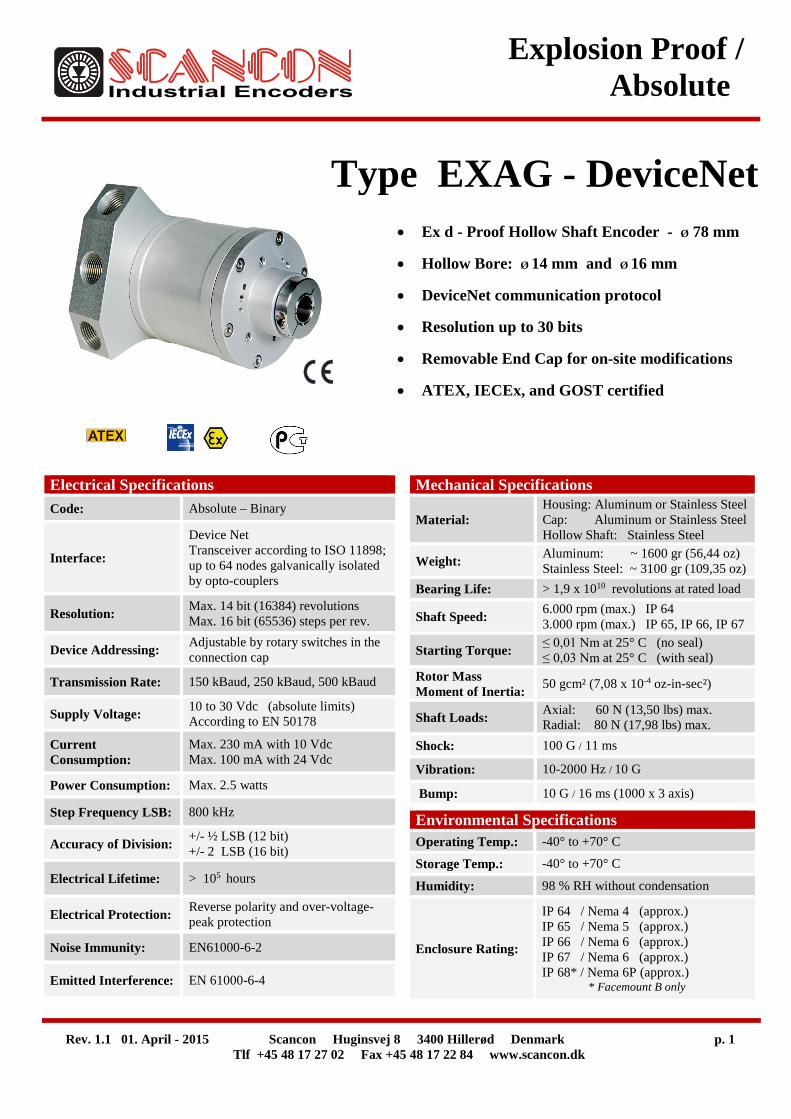
Rev. 1.1 01. April - 2015 Scancon Huginsvej 8 3400 Hillerød Denmark p. 1 Tlf +45 48 17 27 02 Fax +45 48 17 22 84 www.scancon.dk Explosion Proof / Absolute Type EXAG - DeviceNet Mechanical Specifications Material: Housing: Aluminum or Stainless Steel Cap: Aluminum or Stainless Steel Hollow Shaft: Stainless Steel Weight: Aluminum: ~ 1600 gr (56,44 oz) Stainless Steel: ~ 3100 gr (109,35 oz) Bearing Life: > 1,9 x 10 10 revolutions at rated load Shaft Speed: 6.000 rpm (max.) IP 64 3.000 rpm (max.) IP 65, IP 66, IP 67 Starting Torque: ≤ 0,01 Nm at 25° C (no seal) ≤ 0,03 Nm at 25° C (with seal) Rotor Mass Moment of Inertia: 50 gcm² (7,08 x 10 -4 oz-in-sec²) Shaft Loads: Axial: 60 N (13,50 lbs) max. Radial: 80 N (17,98 lbs) max. Shock: 100 G / 11 ms Vibration: 10-2000 Hz / 10 G Bump: 10 G / 16 ms (1000 x 3 axis) Electrical Specifications Code: Absolute – Binary Interface: Device Net Transceiver according to ISO 11898; up to 64 nodes galvanically isolated by opto-couplers Resolution: Max. 14 bit (16384) revolutions Max. 16 bit (65536) steps per rev. Device Addressing: Adjustable by rotary switches in the connection cap Transmission Rate: 150 kBaud, 250 kBaud, 500 kBaud Supply Voltage: 10 to 30 Vdc (absolute limits) According to EN 50178 Current Consumption: Max. 230 mA with 10 Vdc Max. 100 mA with 24 Vdc Power Consumption: Max. 2.5 watts Step Frequency LSB: 800 kHz Accuracy of Division: +/- ½ LSB (12 bit) +/- 2 LSB (16 bit) Electrical Lifetime: > 10 5 hours Electrical Protection: Reverse polarity and over-voltage- peak protection Noise Immunity: EN61000-6-2 Emitted Interference: EN 61000-6-4 Environmental Specifications Operating Temp.: -40° to +70° C Storage Temp.: -40° to +70° C Humidity: 98 % RH without condensation Enclosure Rating: IP 64 / Nema 4 (approx.) IP 65 / Nema 5 (approx.) IP 66 / Nema 6 (approx.) IP 67 / Nema 6 (approx.) IP 68* / Nema 6P (approx.) * Facemount B only • Ex d - Proof Hollow Shaft Encoder - Ø 78 mm • Hollow Bore: Ø 14 mm and Ø 16 mm • DeviceNet communication protocol • Resolution up to 30 bits • Removable End Cap for on-site modifications • ATEX, IECEx, and GOST certified
Transcript of Type EXAG - DeviceNet - Scancon · Type EXAG - DeviceNet Mechanical Specifications Material: ... >...
Rev. 1.1 01. April - 2015 Scancon Huginsvej 8 3400 Hillerød Denmark p. 1 Tlf +45 48 17 27 02 Fax +45 48 17 22 84 www.scancon.dk
Explosion Proof / Absolute
Type EXAG - DeviceNet
Mechanical Specifications
Material: Housing: Aluminum or Stainless Steel Cap: Aluminum or Stainless Steel Hollow Shaft: Stainless Steel
Weight: Aluminum: ~ 1600 gr (56,44 oz) Stainless Steel: ~ 3100 gr (109,35 oz)
Bearing Life: > 1,9 x 10¹⁰ revolutions at rated load
Shaft Speed: 6.000 rpm (max.) IP 64 3.000 rpm (max.) IP 65, IP 66, IP 67
Starting Torque: ≤ 0,01 Nm at 25° C (no seal) ≤ 0,03 Nm at 25° C (with seal)
Rotor Mass Moment of Inertia: 50 gcm² (7,08 x 10⁻⁴ oz-in-sec²)
Shaft Loads: Axial: 60 N (13,50 lbs) max. Radial: 80 N (17,98 lbs) max.
Shock: 100 G / 11 ms
Vibration: 10-2000 Hz / 10 G
Bump: 10 G / 16 ms (1000 x 3 axis)
Electrical Specifications Code: Absolute – Binary
Interface:
Device Net Transceiver according to ISO 11898; up to 64 nodes galvanically isolated by opto-couplers
Resolution: Max. 14 bit (16384) revolutions Max. 16 bit (65536) steps per rev.
Device Addressing: Adjustable by rotary switches in the connection cap
Transmission Rate: 150 kBaud, 250 kBaud, 500 kBaud
Supply Voltage: 10 to 30 Vdc (absolute limits) According to EN 50178
Current Consumption:
Max. 230 mA with 10 Vdc Max. 100 mA with 24 Vdc
Power Consumption: Max. 2.5 watts
Step Frequency LSB: 800 kHz
Accuracy of Division: +/- ½ LSB (12 bit) +/- 2 LSB (16 bit)
Electrical Lifetime: > 105 hours
Electrical Protection: Reverse polarity and over-voltage-peak protection
Noise Immunity: EN61000-6-2
Emitted Interference: EN 61000-6-4
Environmental Specifications Operating Temp.: -40° to +70° C
Storage Temp.: -40° to +70° C
Humidity: 98 % RH without condensation
Enclosure Rating:
IP 64 / Nema 4 (approx.) IP 65 / Nema 5 (approx.) IP 66 / Nema 6 (approx.) IP 67 / Nema 6 (approx.) IP 68* / Nema 6P (approx.) * Facemount B only
• Ex d - Proof Hollow Shaft Encoder - Ø 78 mm
• Hollow Bore: Ø 14 mm and Ø 16 mm
• DeviceNet communication protocol
• Resolution up to 30 bits
• Removable End Cap for on-site modifications
• ATEX, IECEx, and GOST certified
Rev. 1.1 01. April - 2015 Scancon Huginsvej 8 3400 Hillerød Denmark p. 2
Tlf +45 48 17 27 02 Fax +45 48 17 22 84 www.scancon.dk
EXAG DeviceNet / Hollow Shaft
Certifications
ATEX: Certificate No.: TÜV 11 ATEX 084273X II 2 GD Ex db IIC T5 Gb and Ex tb IIIC T100°C Db IP 6x -40C ≤ Tamb ≤ +70C
IECEx: Certificate No.: IECEx TUN 11.0016X Ex db IIC T5 Gb and Ex tb IIIC T100°C Db IP 6x -40C ≤ Tamb ≤ +70C
Nanio: Certificate No.: RU No. 0249626 НАНИО «ЦСВЭ» No.TC RU C-DK.ГБ05.B.00974 1Ex d IIC T5 Gb X Ex tb IIIC T100°C DC Db X -40°C<T.amb<+70°C
ISO 9001 : 2008 Certificate Registration No.: 44 100 111616 Report No: 3508 5281
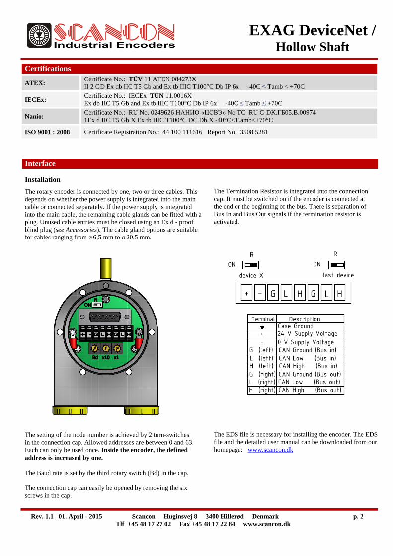
Interface
Installation The rotary encoder is connected by one, two or three cables. This depends on whether the power supply is integrated into the main cable or connected separately. If the power supply is integrated into the main cable, the remaining cable glands can be fitted with a plug. Unused cable entries must be closed using an Ex d - proof blind plug (see Accessories). The cable gland options are suitable for cables ranging from Ø 6,5 mm to Ø 20,5 mm. The setting of the node number is achieved by 2 turn-switches in the connection cap. Allowed addresses are between 0 and 63. Each can only be used once. Inside the encoder, the defined address is increased by one. The Baud rate is set by the third rotary switch (Bd) in the cap. The connection cap can easily be opened by removing the six screws in the cap.
The Termination Resistor is integrated into the connection cap. It must be switched on if the encoder is connected at the end or the beginning of the bus. There is separation of Bus In and Bus Out signals if the termination resistor is activated. The EDS file is necessary for installing the encoder. The EDS file and the detailed user manual can be downloaded from our homepage: www.scancon.dk
Rev. 1.1 01. April - 2015 Scancon Huginsvej 8 3400 Hillerød Denmark p. 3
Tlf +45 48 17 27 02 Fax +45 48 17 22 84 www.scancon.dk
EXAG DeviceNet / Hollow Shaft
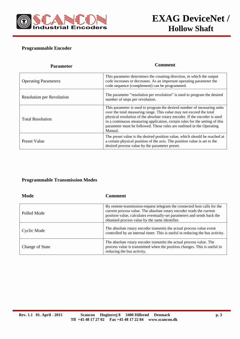
Programmable Encoder
Parameter Comment
Operating Parameters This parameter determines the counting direction, in which the output code increases or decreases. As an important operating parameter the code sequence (complement) can be programmed.
Resolution per Revolution The parameter ”resolution per revolution” is used to program the desired number of steps per revolution.
Total Resolution
This parameter is used to program the desired number of measuring units over the total measuring range. This value may not exceed the total physical resolution of the absolute rotary encoder. If the encoder is used in a continuous measuring application, certain rules for the setting of this parameter must be followed. These rules are outlined in the Operating Manual.
Preset Value The preset value is the desired position value, which should be reached at a certain physical position of the axis. The position value is set to the desired process value by the parameter preset.
Programmable Transmission Modes
Mode Comment
Polled Mode By remote-tranmission-request telegram the connected host calls for the current process value. The absolute rotary encoder reads the current position value, calculates eventually-set parameters and sends back the obtained process value by the same identifier.
Cyclic Mode The absolute rotary encoder transmits the actual process value event controlled by an internal timer. This is useful in reducing the bus activity.
Change of State The absolute rotary encoder transmits the actual process value. The process value is transmitted when the position changes. This is useful in reducing the bus activity.
Rev. 1.1 01. April - 2015 Scancon Huginsvej 8 3400 Hillerød Denmark p. 4
Tlf +45 48 17 27 02 Fax +45 48 17 22 84 www.scancon.dk
EXAG DeviceNet / Hollow Shaft
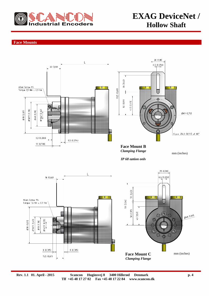
Face Mounts
Face Mount B Clamping Flange
IP 68 option only
mm (inches)
Face Mount C Clamping Flange
mm (inches)
Rev. 1.1 01. April - 2015 Scancon Huginsvej 8 3400 Hillerød Denmark p. 5
Tlf +45 48 17 27 02 Fax +45 48 17 22 84 www.scancon.dk
EXAG DeviceNet / Hollow Shaft
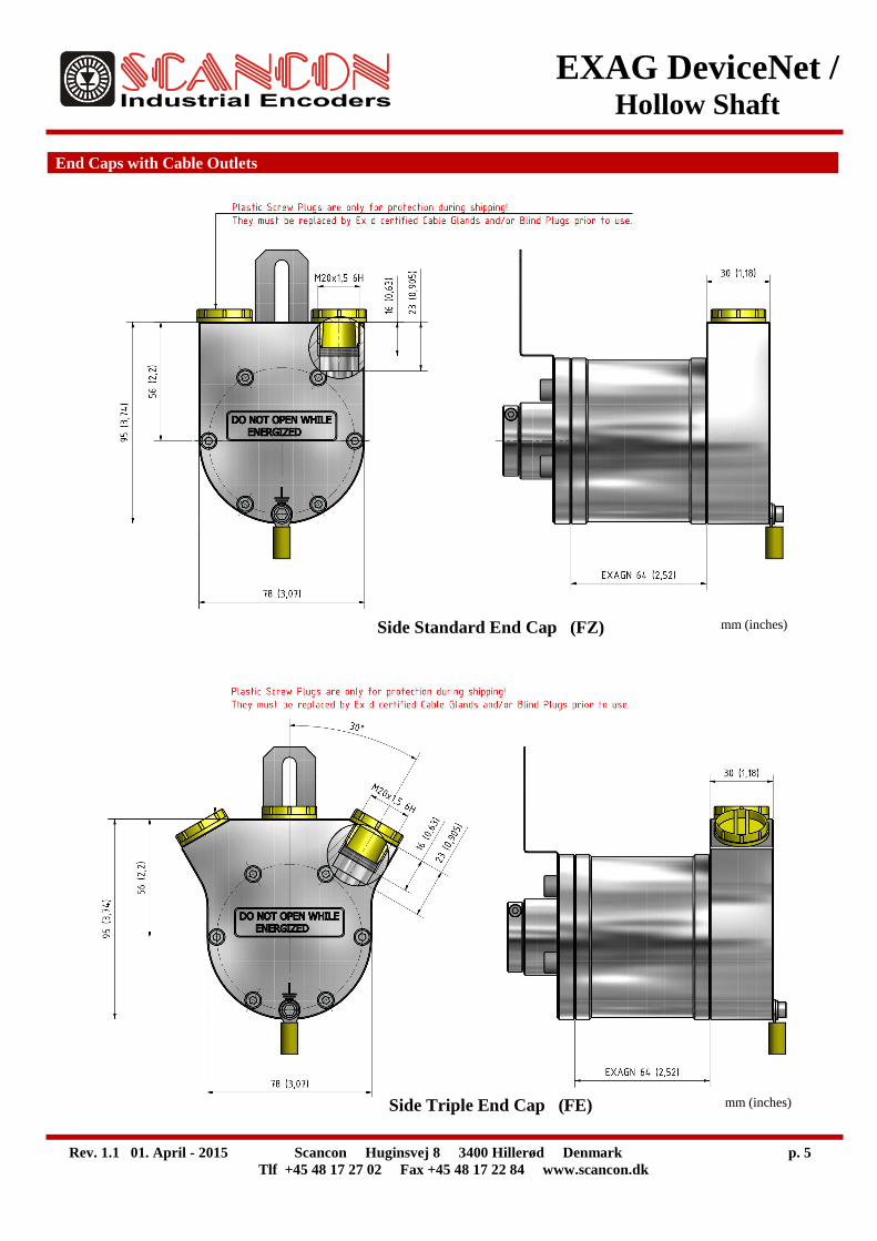
End Caps with Cable Outlets
Side Triple End Cap (FE)
Side Standard End Cap (FZ)
mm (inches)
mm (inches)
Rev. 1.1 01. April - 2015 Scancon Huginsvej 8 3400 Hillerød Denmark p. 6
Tlf +45 48 17 27 02 Fax +45 48 17 22 84 www.scancon.dk
EXAG DeviceNet / Hollow Shaft
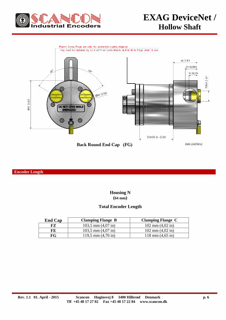
Encoder Length
Housing N (64 mm)
Total Encoder Length
End Cap Clamping Flange B Clamping Flange C FZ 103,5 mm (4,07 in) 102 mm (4,02 in) FE 103,5 mm (4,07 in) 102 mm (4,02 in) FG 119,5 mm (4,70 in) 118 mm (4,65 in)
Back Round End Cap (FG)
mm (inches)

Rev. 1.1 01. April - 2015 Scancon Huginsvej 8 3400 Hillerød Denmark p. 7
Tlf +45 48 17 27 02 Fax +45 48 17 22 84 www.scancon.dk
EXAG DeviceNet / Hollow Shaft
Ordering Code
Example: EXAGN – D2B1B – 12 – 12 – H – AL – 01 – 66 – 00 – FZ – C – S1
Type
EXAG N - D2B1 B - - - H - - - - 00 - - - Housing Interface / Revolutions Steps Hollow Material Hollow IP Cable End Cap Face Accessory Vers. / Code
per Shaft Bore Length with Mount DeviceNet (D2) / Rev. Dimensions Cable
B1 / Binary (B)
Outlets
Aluminum AL Stainless Steel 303 AISI VA Stainless Steel 316 AISI SA
Single Turn 00 Multiturn 12 bits (4096) 12 Multiturn 14 bits (16384) 14
Standard Cable No cable 00
IP 64 64 IP 65 65 IP 66 66 IP 67 67 IP 68* 68
Ø14 mm 01 Ø16 mm Face Mount B option only 02 Ø14 mm Face Mount B – SA option only 03
Spring Couplings 1 hole Face Mount C only p/n 80131046 S1 1 hole Face Mount B only p/n 80131342 S2
See Accessories for Spring Coupling options
64 mm length N See Encoder Length Table
12 bits (4096) (0.090 ) 12 13 bits (8192) (0.040 ) 13 16 bits (65536) (0.0050 ) 16
Side Standard 2 outlets No cable FZ Side Triple 3 outlets No cable FE Back Round 2 outlets No cable FG
See Accessories for Cable Gland options
Clamping flange IP 68 only B Clamping flange C
* Available only with Facemount B