TYPE DR AIR CIRCUIT BREAKER - Electrical Part … · blocks for collecting all the circuit breaker...
53
··' 1.8. 32B INSTRUCTIONS TYPE DR AIR CIRCUIT BREAKER ·�� Efftive September, 1969 Supersedes LB. 35-260-A Dated August, 1955 WESTINGHOUSE ELECTRIC CORPORATION T PISBURGH PNT • SWITCHGêR DIVISION • T PISBURGH, PA U.S.J www . ElectricalPartManuals . com
Transcript of TYPE DR AIR CIRCUIT BREAKER - Electrical Part … · blocks for collecting all the circuit breaker...

··'
1.8. 35-260-B
INSTRUCTIONS TYPE DR AIR CIRCUIT BREAKER
·��·) Effective September, 1969 Supersedes LB. 35-260-A Dated August, 1955
WESTINGHOUSE ELECTRIC CORPORATION EAST PITTSBURGH PLANT • SWITCHGEAR DIVISION • EAST PITTSBURGH, PA
PNd..t Ia U.S.J www . El
ectric
alPar
tMan
uals
. com

RA T ING OF TYPE DR BREAKERS
The Type DR b r e aker is a 750V D.C. s emi-h igh speed
b r e aker designed f o r application on cir cuits ha ving time
current ch aracterist ics which meet the limits esta blished by
NEMA for d.c. breakers of the s e mi-high speed b r e aker class.
Consequent ly, where the system f aul t current (dete r m i n e d w i t h
o u t t h e circuit breaker in t h e circuit) f a l l s between 40000
amperes a n d 125000 amperes at an instant 0. 025 second a f t e r
t h e beginnin g of t h e f ault current transient, the t y p e DR
breaker, equipped w ith instantaneous series overcurr ent trip
p i n g will limit the magnitud e o f f ault current so th a t its
crest is passed not later than 0. 03 second after the be ginnin g
of the fault cur r ent transient.
However, if the m a ximum a vailable current is less than
40,000 amperes at an ins tant 0. 025 seconds after initiat ion
of the fault, the time at which the c r e s t o f f a ult c u r r e n t
is p assed may be g r e a t e r t h a n the r a t e d 0.03 second.
2
\
'!
www . El
ectric
alPar
tMan
uals
. com
COMMUNCIATIONS
"When communic a ting regarding a Product covered
by this Instruct i o n Book, r eplies will b e greatly
f acilita ted by citing complete Name Plate Readi n gs
o f the involved Products. Also, s h ou ld particular
in f o rmation be de sired, please be v e ry c a r e f u l to
c learly and fully state the Problems an d Attendant
C onditions. "
3 www . El
ectric
alPar
tMan
uals
. com

,_
Des cription.
Purpose . . . . . . .
Pro tection from Oust
Unpacking . . .
Description • .
Safety for Personnel
Installation . . . .
INDEX
Control Schemes . . . . . . . .
Adjustment of Contact Arm
Adjustment of Contac t Sequence . . • •
A djustment of Arc Chamber . . .
Adjustment of A uxiliar y Switch
Adjustment of Closing Mech anism
Adjustment of the Cut-Off Switch
Locating cause of Improper Operation
Removal of Parts • . . . . . . .
Series Overload Trip Attachments
I - Instantaneous Trip
II - Inverse Time Limit
Shunt Trip Attachment . . .
Low Voltage Trip Attachment
Reverse Current Trip Attachment . .
Lu brica tion . .
Maintenance .
Renewal Parts .
LIST OF ILLUSTRATIONS
Page
5
5
5
• 5, 6
6,7
7
7
7
7,8
8
8
8
9 9
10 10,11
11 11
11 12
12 12
12 13
Frontispiece
Figure 1. Figure 2. Figure 3. Fig ure 4. .
Figure 5.
Figure 6.
Figure 7, 8 .
.DR Air Circuit Breaker
DR Breaker Assembly • . . . . . Closing Solen oid
• . Au xiliary Switch Reverse current Trip Attachm e n t
• .ov erload Trip Attachment . Low Voltage Trip Attachment
Contr ol S chemes
4
-\
l
www . El
ectric
alPar
tMan
uals
. com
)
(.)·� ' '
TYPE DR AIR CIRCUIT BREAKER
PURPOSE
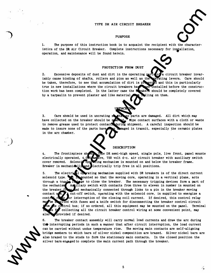
1. The purpose of this instruction book is to acquaint the recipient with the character-
istics of the DR Air Circuit Breaker. Complete instructions necessary for installation,
operation, and maintenance will be found herein.
PROTECTION FROM DUST
2. Excessive deposits of dust and dirt in the operating parts of a circuit breaker invar
iably cause binding of shafts, rollers and pins as well as the operating levers. Care should
be taken, therefore, to see that accumulation of dirt is prevented and this is particularly
true in new installations where the circuit breakers have been installed before the construc
tion work has been completed. In the latter case the breakers should be completely covered
by a tarpaulin to prevent plaster and like material from falling on them.
UNPACKING
3. care should be used in uncrating so that no parts are damaged. All dirt which may
have collected on the breaker should be removed. Wipe contact surfaces with a cloth or waste
to remove grease used to protect contacts during shipment. A careful inspection should be
made to insure none of the parts have been damaged in transit, especially the ceramic plates
in the arc chamber.
DESCRIPTION
4. The frontispiece shows a T,ype DR semi-high speed, single pole, live front, panel mounte
electrically operated, 4,000 ampere, 750 volt d-e. air circuit breaker with auxiliary switch
cover removed. Solenoid operating mechanism is mounted on and below the breaker frame.
Breaker is mechanically and electrically trip free in all positions.
5. The electrical operating mechanism supplied with DR breakers is of the direct current
solenoid type. It is mounted so that the moving core, operating in a vertical plane, acts
through a toggle linkage to close the breaker. The necessary tripping devices form a part of the mechanism. Auxiliary switch with contacts from three to eleven in number is mounted on
the breaker frame and mechanically connected through links to a pin in the breaker moving
contact arm. A cut-off switch, operating with the solenoid core, is supplied to energize a
control relay for interruption of the closing coil current. If desired, this control relay
may be supplied with fuses and a knife switch for disconnecting the breaker control circuit
from the control bus; if so ordered, all this equipment may be mounted on the panel. Terminal
blocks for collecting all the circuit breaker control wiring at some convenient point, may
also be provided if desired.
6. The breaker contact assembly will carry normal load currents and draw the arc during
the interrupting periods in such a manner that after circuit interruption, the load current
can be carried without undue temperature rise. The moving main contacts are self-aligning
bridge members to which bars of silver nickel composition are brazed. Silver nickel bars are
also brazed to the studs to form the stationary main contacts. In the closed position the
silver bars engaged to complete the main current path through the breaker.
5 .. www . El
ectric
alPar
tMan
uals
. com

7. On opening, the main contact bridges, attached to the moving contact arm, part from the
stationary elements first and the arcing (center) bridge second. The lower part of main con
tact is protected from arcing by a parallel shunt and the upper part is protected by secondary
and arcing contacts located above the mains. During the early part of the opening movement
a horizontal barrier system isolates the main contacts from gases thrown downward by the arc.
The stationary portion of the protective contacts are arranged on a spring-mounted platform
which follows the opening contact arm for a short distance. At the lower edge of this plat
form is the secondary contact surface which continues contact with the secondary contacts on
the moving arm until the main contact surfaces are separated a safe distance. Stops then
operate to halt the follow-up movement of the lower portion of the platform, thus acting to
separate the secondary contact surfaces while the arc-drawing members are still permitted to
remain in contact. The arcing contacts part last, consequently the arc is drawn at the ex
treme upper end of the contact structure.
8. The arc chamber is located immediately above the arcing contacts of the breaker; the
insulating sides of the chamber extend downward past the upper contact members to insure a
positive transfer of the arc into the chL�ber. The chamber consists of laterally spaced
ceramic plates having v-shaped slots a� ld together with a moisture and heat resisting
cement. An arcing horn is provided at ·�ar of the chamber. The series of V-shaped slots
in these plates form a vented groove or c extending the full length of the chamber into
which the arc is drawn and extinguished, thus interrupting the circuit.
9. A multi-tum coil, located behind the arc-chamber is inserted into the electrical cir-
cuit by the transfer of the arc from the arcing contact to the arcing horn which is directly
above it. This coil then generates a magnetic flux which is directed across the arc path by
magnetic pole faces that are in the sides of the arc chamber. The flux across the gap between
the pole faces and through the chamber forces the arc upward into the interrupting slot.
10. The arcing contacts are so arranged that at the instant of parting they form a sharp
loop in the current path through the breaker. The magnetic effect of this loop extends the
arc upward very rapidly as the contacts open. Due to this upward looping effect, the arc
almost immediately impinges against the arcing horn in the chamber directly above the station
ary arcing contact so that one terminal of the arc transfers to this horn, the other terminal
remaining on the moving arc contact. Transfer of the arc to this horn alters the current path
through the breaker to include the multi-turn coil mentioned in the preceding paragraph, this
coil is not energized when the breaker is in the closed position. Energizing this coil pro
duces a magnetic circuit which moves the arc upward into the arc chamber.
SAFETY FOR PERSONNEL
11. The installation, operation, and maintenance of circuit breaker equipment requires that
certain precautionary measures be taken to prevent accidents. The following represents sug-
. gestions of that character.
A. 00 l'KJT 1WQI A LIVE BREAKER.
Parts of the circuit breaker attached to the upper stud are at line potential of
the circuit to which the circuit breaker is connected; The breaker should be
isolated from the circuit by a disconnecting switch before attempting any work on
the breaker.
6 www . El
ectric
alPar
tMan
uals
. com

)
,;·)··.:. 'I ,' '··: .
B. Whenever possible the breaker should be in the open position when any work is beinf
done on it. If that is impossible the trigger should be secured in the latched position by inserting a wooden block between the trigger and the frame in such a
manner that it is impossible to move the trigger upward to the tripping position. such a blocking arrangement is also useful when working with the undervoltage
attachment.
IN STALLATION
12. The DR air circuit breaker, complete with all attachments, is a self-contained unit,
and has been mounted, adjusted and calibrated on its own �ermanent panel at the factory. It is designed only to be mounted in a vertical position, and all inspections for proper opera
tion must be made with the breaker panel held vertically. Excessive deposits of dust and dir· in the operating parts of a circuit breaker invariably cause binding of shafts, triggers,
rollers and pins as well as the operating levers.
It is important that the connecting bus be of sufficient current carrying capacity and that connections to the breaker be joined properly. Obviously heat conducted into a breaker from a hot joint will increase the temperature rise of the breaker. Connecting cables or bus should be well supported and braced so that the breaker studs will not be subjected to unnec
essary strain as a result of magnetic forces set up by short circuit currents.
CONTROL SCHEMES
13. TYPical control schemes employing a cutoff switch are shown by figures 7 and 8. It
will be noted that, with either of these schemes, automatic reciprocation of the closing
mechanism (known as pumping) cannot occur should the cutoff switch or breaker mechanism lose its adjustment. The cutoff switch is used to energize a cutoff (Y) relay which in turn ope� the operating coil circuit of the contactor (X), causing the contacts "X" to open the closin�
coil circuit. The "Y" relay remains energized until the control switch is opened and by thi� means "pumping" is avoided.
ADJUSTMENT OF CONTACT ARM
14. To adjust the contact arm, put the arc chamber in the hinged position (see paragraph :
and put the contact arm in a partially closed position. After the bolt which clamps the ecc1 tric pin is loosened the eccentric pin should be turned so that the machined surface of the <
tact arm should be parallel to and 2 5/8 ± 1/16 from the panel (See Fig. *1) when the breake1 is closed. When the contact arm is adjusted to the correct position care should be taken to securely lock the eccentric pin before the breaker is operated again. Before this adjustmen1 should be considered complete inspection should be made by prying each set of contacts gent!� apart with the aid of a large screw driver or similar tool, being careful not to mar the con· tact surfaces.
ADJUSTMENT OF CONTACT SEQUENCE
15. IT IS VERY IMPORTANT 'mAT ADE<lJA'lE SEPARATION BE OBTAINED BETWEEN MAIN CONTACT SURFAC
AT mE INSTANT THE SECXlNDARY CONTACTS PART DURING THE OPENif«J STROKE OF THE BREAKER. THI S separation should be approximately 5/16" for the outer main contacts and approximately 9/32" for the center main contact.
7 www . El
ectric
alPar
tMan
uals
. com

): \
16. This separation can be obtained by first adjusting the contact arm, as per paragraph 14, then adjusting the nut located at the center of the bridging members. To adjust the nut, remove the locking pin and screw down the nut to a point where it just touches the bridge member with the breaker in the closed position, then back off the nut 1/16• for the outer
contacts and 3/32" for the center contacts. (Note: 1/16" corresponds to 5/6 turn of the bridge nut and 3/32" is approximately 1-1/6 turn of the same nu�. See Figure 1. ) Lock con
tacts in position after adjustment with the locking pin. IT SHOULD BE BORNE IN MIND THAT SATISFACIORY PERFORMANCE OF mE BREAKER DEPENDS UPON MAINTAINING miS IMPORTANT ADJUSTMENI'.
ADJU STMENT OF ARC CHAMBER
17. Proper alignment of the arc chamber is obtained when the clearance between the arc tip to each side of the ceramic plates is approximately the same. The machined surfaces at the rear of the arc chamber should also be resting on the spring guard of the stationary arc plat
form and up against the panel. The moving arc tip should not touch the ceramic plates under
any circumstances. SEE PARAGRAPH 29-A FUR 'mE REMOVAL OF 'lliE ARC CHAMBER.
ADJUSTMENT OF AUXILIARY SWITCH
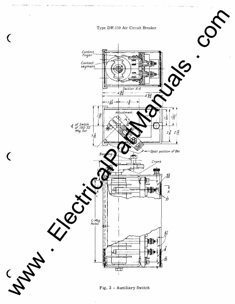
18. Rotary type auxiliary switches are sturdily constructed and provide a variety of com-binations of opening and closing contacts. Positive operation is obtained through an adjustable operating link which connects the rotor crank to the breaker. Proper setting of the auxiliary switch is obtained by adjusting the length of the rotor crank and the length of the
operating link so that the rotor crank pin is at a point 45° above the horizontal when the
breaker is closed and at a point 45° below the horizontal when the breaker is in the extreme
open position. FOr normal application the assembled relation between crank and rotor causes the contact segment nearest the crank to close when the breaker closes.
19. Adjustment of the position of the switch arm with respect to the breaker contact arm
is obtained by varying the length of the operating link by means of the threaded joint.
ADJU STMENT OF CLO SING MECHAN I SM
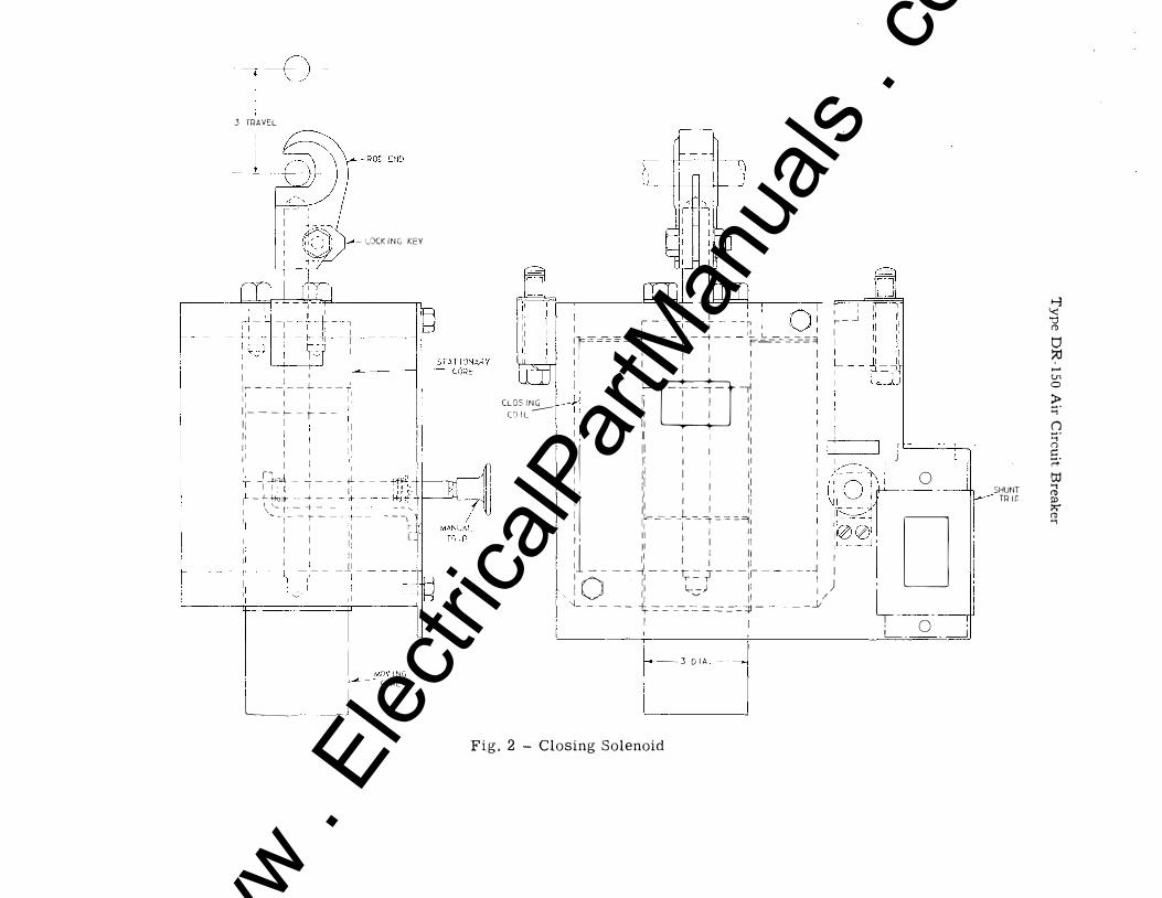
20. To obtain the maximum closing effort from any particular closing magnet, the air gap between the moving and stationary core sections should be as short as practicable at the point in the closing stroke where the force requirement is greatest. The ideal adjustment, therefore, is obtained when the closing linkage is adjusted to provide only the necessary overtravel of the toggle linkage at the position where the magnet cores come together. Attempts to adjust for an abnormal amount of over-travel may cause the stops in the breaker mechanism to meet and thereby needlessly cause high stress in the breaker parts.
21. Adjustment of the length of the closing linkage is provided by means of a threaded
joint on the magnet stem. To readjust the closing linkage loosen the clamping bolt in the
rod end and remove the locking key to free the stem. The length of the stem can then be varied
by turning the moving core at the bottom. Adjustments of less than one-half of a turn cannot be made because the stem is only slotted in two places 180° apart. After adjustment has been made return locking key to original position and tighten clamping bolt. Check to see that moving core operates cut-off switch after the adjustment has been made.
8
j
)
www . El
ectric
alPar
tMan
uals
. com

· !···· · ·) ' ' '
ADJU STMENT OF THE CUT-OFF SWITCH
22. Closing coils are designed to remain energized only momentarily, hence to avoid over-
heating, provision must be made to interrupt the closing coil circuit immediately after the breaker has latched closed. Unless otherwise specified , a small �cutoffft switch having con
tacts which �make� as the cores of the closing magnet come together is mounted on the breaker
frame.
23. Proper adjustment of the cut-off switch requires that its contacts be closed and re
main closed when the moving core reaches the end of its closing stroke. Due to the inertia of the moving parts of the breaker, moving core and contactor, it is practical to permit the
cut-off switch contacts to touch slightly before the core �eaches the end of the stroke.
LOCATING CAU SE OF IMPROPER OPERATION
24. Failure to Trip From OVerload May Be Due To:-
A. Improper setting of current calibration.
B. Friction in tripping details as a result of foreign objects or a broken part.
c. Stray-magnetic fields.
25. Failure to Trip BY Remote COntrol May Be Due To:-
A. Open circuit due to loose connection. B. Burned out trip coil.
26. OVerheating Of The Breaker May Be Due To: -
A. Overload
B. Improper adjustment of spring pressure on main contacts. (Refer to adjustment of contact arm and contact sequence. )
c. Poor condition of main contact surfaces.
27. Excess Burning Of Main Contacts May Be Due To:-
A. Poor contact at the secondary contacts due to an obstruction, surface condition, or
inadequate spring pressure.
B. High resistance of the secondary contact circuit due to loose joining at the upper or lower shunt.
c. Inadequate lead of main contact over secondary contact. (See adjustment of contact sequence. )
28. Failure Of nte Breaker To Stay Closed May Be Due To:-
A. Inadequate over-travel of the toggle linkage to the fully closed position. (See ad
justment of closing linkage. )
9 www . El
ectric
alPar
tMan
uals
. com

REMOVAL OF PART S
29. The following instructions will be helpful if it is necessary to remove parts for
inspection or to make replacements.
A. To Remove the Arc Chamber: Trip the breaker and remove the two bolts that holds the
arc chamber to the panel. Then pull the arc chamber towards you and 1ift up and when
the arc chamber clears the moving contact arm then lift the arc chamber from the pins.
The above procedure should be reversed for mounting the arc chamber on the panel.
s. To Remove the Moving Arcing Contact: The three tap bolts should be removed from the back of the moving contact support. These bolts are made of non-magnetic material and substitution of steel bolts should be avoided.
c. To Remove the Stationary Arcing contact: Trip the breaker and put the arc chamber in the hinged position. (See paragraph 29F). Then remove the two bolts that holds the
stationary arcing contact bracket to the panel.
D. To Remove the Coil from the Closing Magnet: Remove the cover from the front of the
assembly. Disconnect wires from the closing coil and the cut-off switch. Remove the
locking key on the threaded brass rod by removing the clamping bolt in the rod end. Unscrew brass rod by turning moving core from bottom. The moving core and stem will
then slip out. Now the magnet frame can be removed by removing the bolt· at each side
of the frame. The closing coil is removed after the stationary core is withdrawn.
E. To Remove the Oil Pot of the Inverse-time-limit OVerload Attachment:
(1) Loosen knob on the overload dash pot.
(2) TUrn dash pot until the index is about 45° off the scale at either the 0 or
100 end.
(3) Remove dash pot by pulling straight downward.
(4) To replace dash pot reverse the above procedure.
F Arc Chamber in the Hinged Position: To put the arc chamber in this position trip the breaker and remove the two bolts that hold the arc chamber to the panel. Then hY pulling the arc chamber towards you and lifting up the arc chamber until you can insert a 7 in. or longer 1/2 Dia. bolt or steel rod into the 5/8 Dia. hole in the hinged brackets. Then let the arc chamber rest on the bolt or the steel rod. See Fig . N1. The
arc chamber must be bolted to the panel before the breaker is put in service.
SERIE S OVERLOAD TRIP ATTAc:HMENTS
30. Series overload trips are used to trip the circuit breaker whenever the current through the breaker exceeds a predetermined value. This device includes a one turn stationary magnetic
circuit mounted around the lower stud of the breaker, and a movable iron armature. The armature is mounted in such a way that as it moves under magnetic attraction to reduce the air gap, it
provides the force to trip the breaker latch. The amount of current required.to start the
armature is a function of air gap length and upon this principle all overload trips for DR · breakers are calibrated.
31. The tripping magnet is used at its best efficiency when adjusted so that, of the total
travel of the armature, that part used to move the breaker trigger should be just long enough to
trip the trigger free of the toggle latch. With this adjustment the maximum amount of armature travel is used to obtain momentum for tripping the breaker.
10 www . El
ectric
alPar
tMan
uals
. com

32. Each overload trip unit is calibrated on the breaker at the factory. Powerful stray
magnetic fields affect the calibration points to some extent on large breakers. Where the bus arrangement of the switcHboard is known, the breakers are calibrated at the factory with
the same arrangement.
33. All the overload trip devices reset themselves automatically. That is, after tripping,
they automatically return to their original position.
I - Instantaneous Trip
34, Instantaneous trip attachments are designed to be calibrated on currents close to the
breaker rating. The standard range of calibration is 100% to 200% of the normal 30° c. rating
of the breaker. Unless otherwise specified, the five main p6ints 100%, 125%. 150%, 175% and
200% are stamped on the scale plate.
II - Inverse Time Limit
35. The Inverse-time-limit attachment consists of a tripping device with the addition of a
time delay device which prevents tripping on a relatively small overload which lasts but a short
time.
36. The time delay feature is obtained by the sucker action between a smooth surface metal
disc which is attached to the overload armature and which normally rests on the smooth bottom
surface of a pot containing a small quantity of oil (approximately 1/s• deep). The resulting
sucker action retards the starting of the overload armature, the time of delay being approxi
mately inverse to the magnitude of the overload.
37. A limited variation in the time delay can be obtained by turning the pot which varies
the amount of surface in contact between the sucker and pot. FUrther variation can be obtained
by using oils of different viscosities.
38. The overload trip device is calibrated without oil in the pot. The calibration range
and scale markings for the standard Inverse-time-limit attachment is the same as for the
Instantaneous Trip Attachment.
39. To insure reliable performance of the time delay device, it is important that oil in
the pot be kept clean. A single particle of dirt between the sucker surfaces may greatly
reduce the time delay. To remove imperfections in the sucker surfaces due to bruising or other
causes, it is suggested that all high spots be removed with a scraper. A paper washer is
placed between the sucker surfaces to protect them during shipment. This washer should be
removed when placing tr.q breaker in service and before oil is placed in the pot.
40. FOr instructions on removing the oil pot of the Inverse-time-limit attachment, see
paragraph 29-E.
SHUNT TRIP ATTACHMENT
41. The shunt trip attachment is designed to trip the breaker'
when the trip·coil is energize
by an auxiliary circuit, thus providing for remote control and various interlocking arrange
ments. Shunt trip coils are designed to remain energized only momentarily, hence provisions
should be made to interrupt the shunt trip circuit immediately after the breaker has been
tripped. It is common practice to obtain this result by means of an auxiliary switch having
contacts which open as the breaker opens.
11 www . El
ectric
alPar
tMan
uals
. com
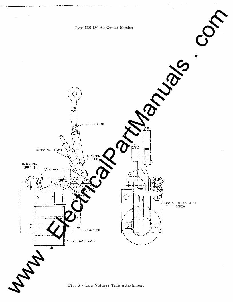
LOW VOLTAGE TRIP ATTACHMENT
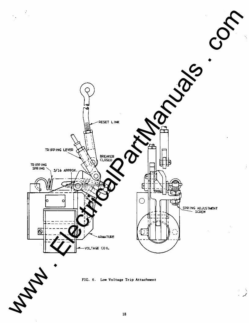
42. The low voltage attachment is mounted on the panel to the left of the breaker and operates to trip the breaker if the control voltage drops below a predetermined value.
43. The important elemerts of this device function as follows: - When energized at rated
voltage, magnetic force holds the armature to the stationary core against the action of the
stressed tripping spring. If the applied voltage decreases to a value at which the magnetic attraction for the armature is less than the force exerted by the tripping spring, the arma
ture ndrops out• and the breaker is tripped by energy from the tripping spring. The armature is reset mechanically through links attached to the breaker.
44. To adjust for drop-out at a given voltage, apply rated voltage and close breaker then reduce voltage to the desired drop-out value and adjust screw to the position which causes the armature to drop-out. This setting should be checked by repeating the above procedure. For normal applications this device is adjusted to drop-out at 3� to 60% of the rated volt
age.
REVERSE CURRENT TRIP ATTACHMENT
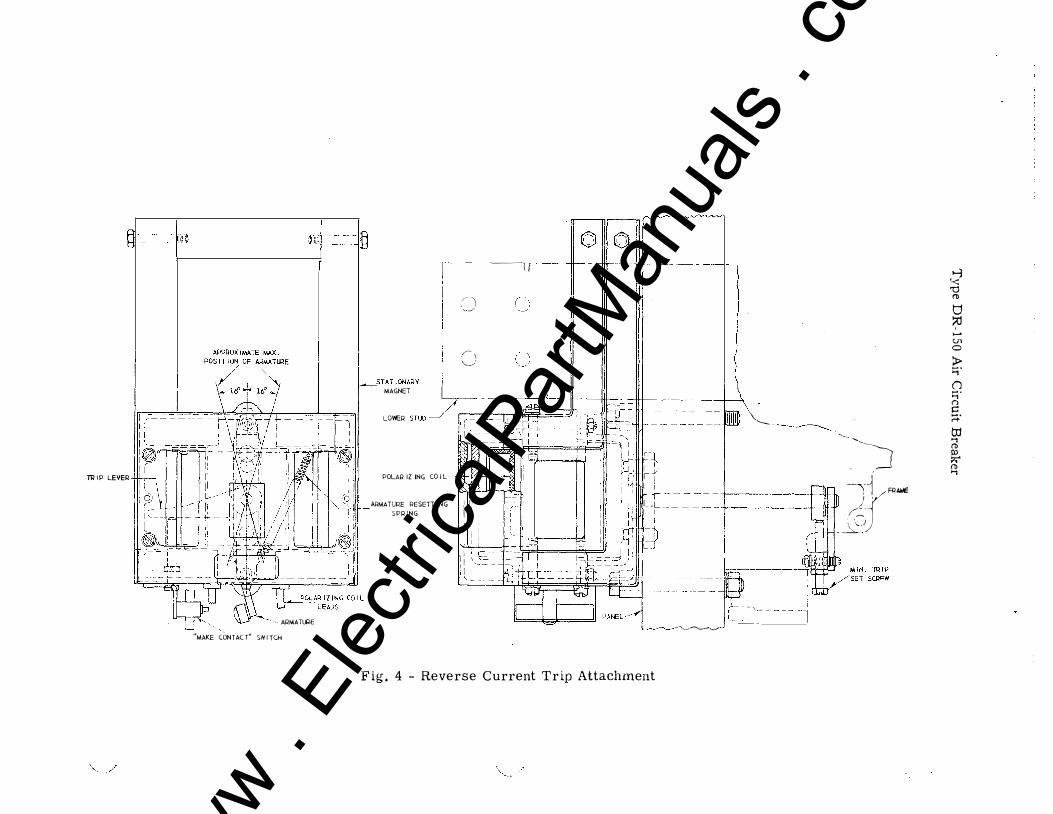
45. The reverse current trip attachment is used to trip the breaker when the direction of
current flow through the breaker is reversed.
46. The reverse current trip mechanism consists of a stationary magnet energized by a
series current coil and movable armature energized by a polarizing coil. When the series coil current is flowing in the normal direction the armature tends to rotate in one direction but
is restrained by a stop. When the series current reverses, the armature is rotated in the
opposite direction against a spring to trip the breaker. This adjustment is set at the minimum trip value which is approximately 250 amperes.
47. The reverse current armature is reset after a tripping operation by opening the polar
izing coil circuit. This can be accomplished by wiring the polarizing coil through an auxil· iary switch on the breaker.
LUBRICATION
48. Lubrication of the mechanism as applied at the factory should be sufficient for years
of service. It should be remembered that oily surfaces promote the accumulation of dirt and
for that reason contact surfaces should be kept free· from oil or grease. It is recommended that no lubricants be applied to the breaker.
MAINTENANCE
49. It would be difficult to over-emphasize the importance of adequate care of all protec-tive devices. To assure proper functioning, they should be the subject of periodical, system
atic and intellegent inspection. Even the smallest details of required maintenance should
not be neglected if costly failures of equipment and service are to be avoided. Maintenance
must include occasional checks on calibration as well as on the co-ordination and freedom of all moving parts. The frequency and character of inspection will for the most part be a matter of experience. In general, light monthly inspection, with a thorough inspection semiannually, should be a minimum. The Company will be glad to furnish such additional information as may be needed to amplify or clarify these instructions.
12
)
www . El
ectric
alPar
tMan
uals
. com

www . El
ectric
alPar
tMan
uals
. com

,_;J'.·· .. (, ·''
\ '.: '
RENEWAL PARTS
50. When ordering renewal parts, specify the name of the part desired. Give the breaker
type, amperes, volts and Stock Order Number (S. O. No. ) as found engraved on the breaker
nameplate.
BLOWOUT ASSEMBLY
CONTACT LUD IN INCHII
AIICING T., TOUCHING
SECONOAIIY TIP TOUCHING
CENTER BRIDGE TOUCHINI
/� / -�
/ � . � / ' I ) I . . I l_ .
� I
MAIN
1/1 5/11 1/lZ
SECON-DAllY
1/4 0
0
............ .
FIG. 1. Type "I:R" Breaker Assembly
13 www . El
ectric
alPar
tMan
uals
. com

. ' -l
-�·== �:J L2 !OJ -; : D �', o--�)-;-�.:.,--_j--_ j_ ___ _j__
I II A;:\: - - - - - L = : ::;!-' _'Jtf J
-- nr---
-- - - - - - - ..
0 '" - - - - - - - -
....._
,,, - - ---- - '
,,, ;-- �
I''
I I
'I
I
- - - _,,
I I
_ c. _ ,IL.. _
I : - : --r-��-----= ,�---� "n",,. ,�--:
_:_�---o :: : --�-I r -- - _ _
p I
_ I 1 I
- - - - 1t- - - - - 1 II
-,--1--- - - - ,1 t,...-,. II
I 1 I - - - - - - -+1- _
I 1 �) II
I
I -- � -" 1
0
I I 'I I I
L _,,... ___ j,.., __
I, I 1:
1;; ---= = = =--=--=----=-..1.-=- _ _ I II
"'
- - -=--r------¥- - -r---'---�J
1:: I I
111 I I
------ :o' --- ---=-=-=.:..-=-::1 __ �
14
"0 ... 0 c 41 -
� till c ...
8 -u
www . El
ectric
alPar
tMan
uals
. com

FIG. 3. Auxiliary Switch
15 www . El
ectric
alPar
tMan
uals
. com

,_ Q)
TA IP L.EVEA
."'-._
.:._,.';
APAIOXIWATE WAX . POSIT I� OF -TIRE
I
"IIAICE CONTACT" SWITCH
STAT IOIWIY MACiEl
LOIEII S Tl.O
©Ill© ,.______,, B - Ill Ill - -+-,
0 ('"\ · .... j
()
- -------
POUIIIZI!;<i COIL I .1 I .!) I I
AAIIIATIAE AESETTIN<i.. SPAINCi
I I I .- --- --- r------_r_ I --L I I -- ---- r------...1 I I
=i
� "_)
� .JYFQAWE �_;)
---IIIIN. TRIP
-----SET�
FIG. 4. Reverse Current Trip Attachment
_ _,
I
www . El
ectric
alPar
tMan
uals
. com

.... �
l!:;-, �r--····· �/
I
.J
BKR. BASE
MECH.
LEVER
ARMATURE
""'=-- ARMATURE
. ..._.,,
SPACER ... 'l l"'l"" I u I:J ADJUSTING SCREW 11 ,..,.
INSTANTANEOUS TRIP TIME ceuv TRIP
FIG. s. Overload Trip Attachments
J
www . El
ectric
alPar
tMan
uals
. com
TRIPPING SPRING
RESET LINK
FIG. 6. Low Voltage Trip Attachment
18 www . El
ectric
alPar
tMan
uals
. com

.)
;'·.: .. )''.· I ·• • · '
��.�;·
N
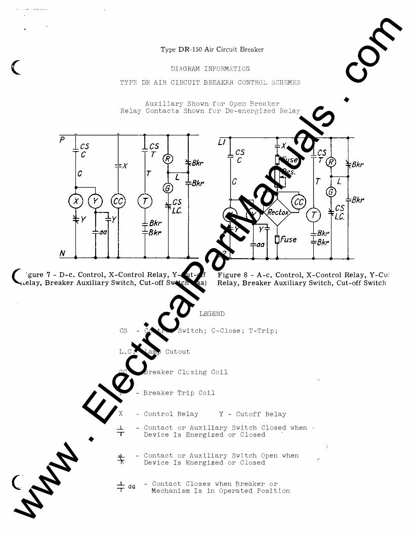
DIAGRAM INFORMATION
TYPE DR AIR CIRCUIT BREAKER CONTROL SCHEMES
Auxiliary Shown for Open Breaker Relay Contacts Shown for De-energized Relay
L2
FIG. 7. D-C. Control, X-Control Relay, Y·CUt-off Relay, Breaker Auxiliary Switch,
Cut-off Switch (aa)
FIG. 8. A-C. COntrol, X-Control Relay,
Y-CUt-off Relay, �eaker Auxiliary Switch,
CUt-off Switch (aa)
LEGEND
cs -. control Switch; C-Close; T-Trip;
L.C. - Lamp CUtout
cc - Breaker Closing COil
T - Breaker Trip Coil
X
..L T
- COntrol Relay Y - CUtoff Relay
- Contact or Auxiliary SWitch Closed when Device Is Energized or Closed
- Contact or Auxiliary Switch Open when Device Is Energized or Closed
_L - Contact Closes when Breaker or
1 Q.(). Mechanism Is in Operated Position
19 www . El
ectric
alPar
tMan
uals
. com

p
N
cs c
Type DR-150 Air Circuit Breaker
DIAGHAM INFORMATION
TYPE DR AIR CIRCUIT BREAKEH CONTROL SCHEMES
Auxiliary Shown for Open Breaker Relay Contacts Shown for De-energized Relay
cs T
T
Ll cs c
c T
Bkr
Bkr :;.
_,
- --:� ·!',""" .. �
'
1 . ·�
I l ' .
.. •• i 1 • � '�.; i � �lif\i
A.gure 7 - D-e. Control, X-Control Relay, Y -Cut-off '";lay, Breaker Auxiliary Switch, Cut-off Switch (aa)
L2 J .. Figure 8 -A-c. Control, X-Control Relay, Y-Cut-�f ·
Relay, Breaker Auxiliary Switch, Cut-off Switch (aa)
LEGEND '
CS - Control Switch; C-Close; T-Trip; '-· .
L.C. -Lamp Cutout
cc
T
X
...L T
- Breaker
Breaker
Clc sint; �il
..::�·--( .. ' T%_iP �o�t" ·-
'.• ..
- Control Relay Y - Cutoff Relay
- Contact or Auxiliary Switch Closed when Device Is Energized or Closed
- Contact or Auxiliary Switch Open when bevice Is Energized or Closed
� aa - Contact Closes when Breaker or -r Mechanism Is in Operated Position
I It ••
· • • 1-
I ·· · r ;
,. \,'!-· ·n�'h
www . El
ectric
alPar
tMan
uals
. com
,, ,,.
f ' I i
TYPE DR-180 AIR CIRCUIT BREAKER
Westinghouse Electric Corporation East Pittsburgh, Pa.
Prmted in U.S.A. (Reprinted 8·53) I. B. 35-260 www . El
ectric
alPar
tMan
uals
. com

www . El
ectric
alPar
tMan
uals
. com

(
(
c
TYPE DR-150 AIR CIRCUIT BREAKER
P URPOSE
l. The purpose of this instruction book is to acquaint the recipient with the characteristics of the DR-150 Air Circuit Breaker. Complete instructions necessary for installation, operation, and maintenance will be found herein. The type DR air circuit breaker is rather new, however, its operation is similar to that of any low voltage air circuit breaker.
DESCRIPTION
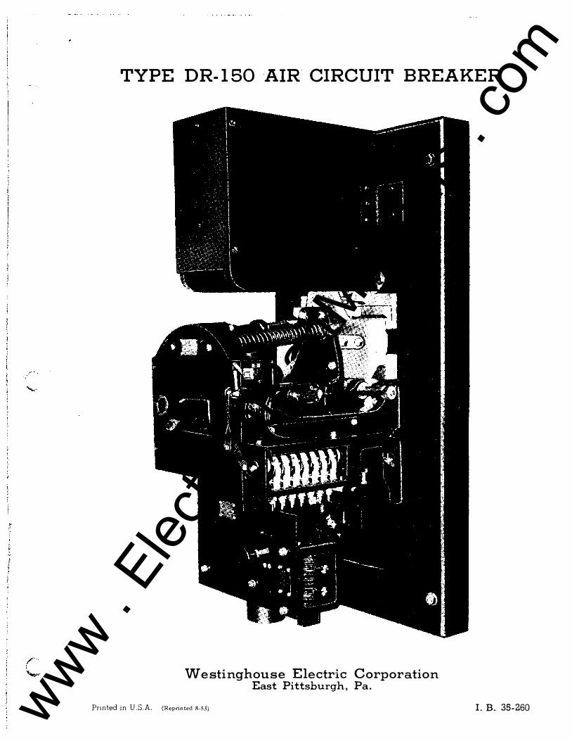
2. The frontispiece shows a Type DR-150, semi-high speed, single pole, live front, panel mounted, electrically operated, 8000 ampere, 750 'Jolt d-e. air circuit breaker with auxiliary switch cover removed. The published interrupting rating is 150,000 amperes. Solenoid operating mechanism is mounted on and below the breaker frame. Breaker is mechanically and electrically trip free in all positions.
3. The electrical operating mechanism supplied with DR breakers is of the direct current solenoid type. It is mounted so that the moving core, operating in a vertical plane, acts through a toggle linkage to close the breaker. The necessary tripping devices form a part of the mechanism. Auxiliary switch with contacts from three to eleven in number is mounted on the breaker and mechanically connected through links to the breaker contacts. A cut-off switch, operating with the solenoid core, is supplied to energize a control relay for interruption of the closing coil current. If desired, this control relay may be supplied with fuses and a knife sv1itch for disconnecting the breaker control circuit from the control bus; if so ordered, all this equipment may be mounted on the panel. Terminal blocks for collecting all the circuit breaker control wiring at some convenient point, may also be provided if desired.
4 . The breaker contact assembly will carry normal load currents and draw the arc during the interrupting periods in such a manner that after circuit interruption, the load current can be carried without undue temperature rise. The moving main contacts are self-aligning bridge members to which bars of silver nickel composition are brazed. Silver nickel bars are also brazed to the studs to form the stationary main contacts. In the closed position the silver bars engage to complete the main current path through the breaker.
5. On opening, the main contact bridges, attached to the moving con-tact arm, part from the stationary elements first and the arcing ( center ) bridge second. The lower part of main contact is protected from arcing by a parallel shunt and the upper part is protected by secondary and arcing contacts located above the mains. During the early part of the opening movement a horizontal barrier system isolates the main contacts from gases thrown downward by the arc. The stationary portion of the protective contacts are arranged on a spring-mounted platform which follows the opening contact arm for a short distance. At the lower edge of this platform is the secondary contact surface which continues contact with the secondary contacts on the moving arm until the main contact surfaces are separated a safe distance. Stops then operate to halt the follow-up movement of the lower portion of the platform, thus acting to separate the secondary contact surfaces while the arc-drawing members are still permitted to remain in contact. The arcing contacts part last, consequently the arc is drawn at the extreme upper end of the contact structure.
l www . El
ectric
alPar
tMan
uals
. com

www . El
ectric
alPar
tMan
uals
. com

Type DR-150 Air Circuit Breaker
6. The arc chamber is l ocated immediatel y above the arcing contacts of the breaker; the insul ating sides of the chamber extend downward pa st ths upper contact members to insure a positive transfer of the arc into the chamber. The chamber consists of l ateral l y spaced ceramic pl ates having ,_
shaped sl ots and hel d together with a moisture and heat resisting cement. An arcing horn is provided at the rear of the chamber. The series of ��shaped sl ots in these pl ates form a vented groove or sl ot extending the f ull l ength of the chamber into which the arc is drawn and extinguishe d, thus interrupting the circuit.
7. A mul ti-turn coil , l ocated behind the arc-chamber is inserted into the electrical circuit by the transfer of the arc from the arcing contact to the arcing horn which is directl y above it. This coil then ge nerates a magnetic fl ux which is d irected across the arc path by magnetic pol e f aces that are in the sides of the arc chamber. The fl ux across the gap between the pol e faces and through the chamber forces the arc upward into the inte rrupting sl ot.
8. The arcing contacts are so arranged that at the instant of parting they form a sharp l oop in the current path through the breaker. The magnetic effect of this l oop extends the arc upward very rapidl y as the contact s open. Due to this upward l ooping effect, the arc almost immediatel y impinges against the arcing horn in the chamber d irectl y above the stationary arcing contact so that one terminal of the arc transfers to this horn, the other terminal remaining on the moving arc contact. Transfer of the arc to this horn al ters the current path through the breaker to incl ude the mul ti-turn coil mentioned in the preceding paragraph, this coil is not energized when the breaker is in the cl osed position. Energizing this coil produces a magnetic c;ircuit which moves the arc upward into the arc chamber.
SAFETY FOR PERSONNEL
9. The install ation, operation, and maintenance of circuit breaker equipment requires that certain precautionary measures be taken to prevent accidents. The fol l owing represents suggestions of that character.
A. Do Not Touch a Live Breaker.
Parts of the circuit breaker attached to the upper stud are at line potential of the circuit to which the circuit breaker is connected. The breaker shoul d be isol ated from the circuit by a disconnecting switch before attempting any work on the breaker.
B. W henever possible the breaker shoul d be in the open position when any work is being done on it. If that is impossible the trigger shoul d be secured in the l atched position by inserting a wooden bl ock between the trigger and the f rame in such a manner that it is impossibl e to move the trigger upward to the tripping position. Such a bl ocking arrangement is al so useful when working with the undervol tage attachment.
UNPACKING
10. Care should be used in uncrating so that no parts are damaged. All dirt which may have col l ected on the breaker should be removed. W ipe contact surfaces with a cl oth or waste to remove grease used to protect contacts during shipment. A careful inspection shoul d be made to insure none of the parts have been damaged in transit, especial l y the ceramic pl ates in the arc chamber.
2
} /
www . El
ectric
alPar
tMan
uals
. com

www . El
ectric
alPar
tMan
uals
. com

(
(
(
Type DR-150 Air Circuit Breaker
INSTALLATION AND STORAGE
ll. The DR air circuit breaker, complete with all attachments, is a self-contained unit, and has been mounted, adjusted and calibrated on its own permanent panel at the factory. It is designed only to be mounted in a vertical position, and all inspections for proper operation must be made with the breaker panel held vertically. Excessive deposits of dust and dirt in the operating parts of a circuit breaker invariably cause binding of shafts, triggers, rollers and pins as well as the operating levers. Care should be taken, therefore, to see that accumulation of dirt is prevented and this is particularly true in new installations where the circuit breakers have been installed before the building construction work has been completed. In the latter case the breakers should be completely covered by a tarpaulin to prevent plaster and like material from falling on them. If breakers are to be stored, they should be kept clean and dry.
POWER CONNECTIONS
12. It is important that the connecting bus be of sufficient current carrying capacity and that connections to the breaker be joined properly. Obviously heat conducted into a breaker from a hot joint will increase the temperature rise of the breaker. Connecting cables or bus should be well supported and braced so that the breaker studs will not be subjected to unnecessary strain as a result of magnetic forces set up by short circuit currents.
CONTROL SCHEMES
13. Typical control schemes employing a cutoff switch are shown by figures 7 and 8. It will be noted that, with either of these schemes, automatic reciprocation of the closing mechanism (known a.s pumping) cannot occur should the cutoff switch or breaker mechanism lose its adjustment. The cutoff switch is used to energize a cutoff (Y) relay which in turn opens the operating coil circuit of the contactor (X), causing the contacts "X" to open the closing coil circuit. The "Y" relay remains energized until the control switch is opened and by this means "pumping" is avoided.
ADJUSTMENT OF CONTACT ARM
14. To adjust the contact arm, remove the arc chamber (see paragraph 29-A) and close the breaker. The machined surface of the contact arm should be parallel to and 2-5/8 + l/16" from the panel (see Figure l). Before this adjustment should be considered complete, inspection should be made to insure that all floating contact members remain free. This check is readily made by prying each set of contacts gently apart with the aid of a large screw driver or similar tool, being careful not to mar the contact surfaces.
ADJUSTMENT OF CONTACT SEQUENCE
15. IT IS VERY IMPORTANT THAT ADEQUATE SEPARATION BE OBTAINED BETWEEN MAIN CONTACT SURFACES AT THE INSTANT THE SECONDARY CONTACTS PART DURING THE OPENING STROKE OF THE BREAKER. THIS separation should be approximately 3/16" for the outer main contacts and approximately 5/32" for the center main contact.
16. This separation can be obtained by first adjusting the contact arm, as per paragraph 14, then adjusting the nut located at the center of the bridging members. To adjust the nut, remove the locking pin and scrs-w down the nut to a. point where it just touches the bridge member "lv i th the
3 www . El
ectric
alPar
tMan
uals
. com

www . El
ectric
alPar
tMan
uals
. com

Type DR-150 Air Circuit Breaker
breaker in the closed position, then back off the nut l/16" for the outer contacts and 3/32" for the center contacts. (Note: l/16" corresponds to 5/6 turn of the brid ge nut and 3/32" is approximately l-l/6 turn of the same nut. See Figure L) Lock contacts in position after adjustment with the locking pin. It should be borne in mind that satisfactory performance of the breaker d epends upon maintaining this important adjustment.
ADJUSTMENT OF ARC CHAMBER
17. Proper alignment of the arc chamber is obtained when the clearance between the arc tip to each side of the ceramic plates is approximately the same. The machined surfaces at the rear of the arc chamber should also be resting on the spring guard of the stationary arc platform and up against the panel. Th� moving arc tip should not touch the ceramic plates under any circumstances. SEE PARAG RAPH 29-A FOR THE REMOVAL OF THE ARC CHAMBER.
ADJUSTMENT OF AUXILIARY SWITCH
18. Rotary type auxiliary switches are sturdily constructed and pro-vide a variety of combinations of opening and closing contacts. Positive operation is obtained through an adjustable operating link which connects the rotor crank to the breaker. Proper setting of the auxiliary switch is obtained by adjusting the length of the rotor crank and the length of the operating link so that the rotor crank pin is at a point 45 ° above the horizontal when the breaker is closed and at a point 45° below the horizontal when the breaker is in the extreme open position. For normal application the assembled relation between crank and rotor causes the contact segment nearest the crank to close when the breaker closes.
19. Ad justment of the position of the switch arm with respect to the breaker contact arm is obtained by varying the length of the operating link by means of the threaded joint.
ADJUSTMENT OF CLOSING MECHANISM
20. To obtain the maximum closing effort from any particular closing magnet, the air gap between the moving and stationary core sections should be as short as practicable at the point in the closing stroke where the force requirement is greatest. The ideal ad justment, therefore, is obtained when the closing linkage is ad justed to provide only the necessary overtravel of the toggle linkage at the position where the magnet cores come together. Attempts to ad just for an abnormal amount of over-travel may cause the stops in the breaker mechanism to meet and thereby needlessly cause high stress in the breaker parts.
21. Ad justment of the length of the closing linkage is provided by means of a threaded joint on the magnet stem. To readjust the closing linkage loosen the clamping bolt in the rod end and remove the locking key to free the stem. The length of the stem can then be varied by turning the moving core at the bottom. Adjustments of less than one-half of a turn cannot be made because the stem is only slotted in two places 180° apart. After adjustment has been made return locking key to original position and tighten clamping bolt. Check to see that moving core operates cut-off Sivitch after the ad justment has been made.
4 www . El
ectric
alPar
tMan
uals
. com

www . El
ectric
alPar
tMan
uals
. com

(
(
(
Type DR-150 Air Circuit Breaker
ADJUSTMENT OF T HE CUT-OFF SWITCH
22. Closing coils are designed to remain energized only mome ntarily, hence to avoid overheating, provision must be made to inte rrupt the closing coil circuit immediately after the breaker has latched closed. Unle ss otherwise specified, a small "cutoff" switch having contacts 1.;rhich "make" as the cores of the closing magnet come together is mounte d on the breaker frame.
23. Proper adjustment of the cut-off switch require s that its contacts be closed and remain closed when the moving core reache s the end of its closing stroke. Due to the inertia of the moving parts of the bre aker, moving core and contactor, it is practical to permit the cut-off switch contacts to touch slightly before the core reaches the end of the stroke.
24.
25.
26.
27.
28.
LOCATING CAUSE OF IMPROPER OPERATION
Failure To Trip From Overload May Be Due To:-
A. Improper setting of current calibration. B. Friction in tripping details as a result of foreign objects or a
broken part. C. Stray-magnetic fie lds.
A. B.
A. B.
c.
A.
B.
c.
A.
Failure To Trip By Remote Control May Be Due To:-
Open circuit due to loose connection. Burned out trip coil.
Overheating Of The Breaker May Be Due To:-
Overload Improper adjustment of spring pressure on main contacts. (Refer to adjustment of contact arm and contact sequence. ) Poor condition of main contact surfaces.
Excess Burning Of Main Contacts May Be Due To:-
Poor contact at the secondary contacts due to an obstruction, surface condition, or inadequate spring pressure.
High resistance of the secondary contact circuit due to loose joining at the upper or lower shunt.
Inadequate lead of main contact over secondary contact. (See adjustment of contact sequence. )
Failure Of The Breaker To Stay Closed May Be Due To:-
Inadequate over-travel of the toggle linkage to the fully close d position. (See adjustment of closing linkage. )
RE MOVAL OF PARTS
29. The following instructions will be helpful if it is necessary to remove parts for inspection or to make replacements.
A. To Remove the Arc Chamber: Trip the breaker and remove the four bolts that hold the arc chamber to the panel. The arc chBmber should be lifted up and pulled out at an incline. DO NOT PULL DIRECTLY FORWARD. (An asbestos plate is located partially be hind
5 www . El
ectric
alPar
tMan
uals
. com

www . El
ectric
alPar
tMan
uals
. com

Type DR-150 Air Circuit Breaker
the stationary arc contact and wil l be broken if the arc chambe r is pul l e d d ire ctl y forward. ) T he above proce d ure should be re ve rsed for mounting the arc chambe r on the pane l .
B. T o Re move the Moving Arcing Contac t: T he three tap bol ts should be removed from the back of the moving contact support . T he se bolts are mad e of non-magne tic mate rial and substitution of ste e l bol ts should be avoid e d .
C . T o Re move the Stationary A rcing Contact: T rip the bre aker and re move the arc chambe r. ( See paragraph 29-P. . . ) F rom the re ar of the pane l , re move the two l /4" bolts which support the arc ti p spr i ng pl ate . Pre cautions should be take n to avoid injury w he n re l e asi ng the e ne rgy in the partial ly compre ssed spring by hol d ing the spri ng compre sse d with the aid of a short be am of wood or simi l ar ob j e ct until both bol ts are comple te ly re moved . Re move the remaining bol t and fl at he ad scre w from e ithe r one of the stop b racke ts w hi ch pe rmits the re mov al of the stop bracke t and the guid e pin . By til ting the l owe r e d ge of the contact pl atform aw ay from t he pane l the se cond ary contact springs and insul ating washe rs may be re moved . W ith a scre w d rive r pe rform the final ope ration of remov ing the bolts which hold the e ncl osed shunt to the uppe r st ud .
D . T o Re move the Coil f rom the Cl osing Magne t : Re move the cover f rom the f ront of the asse mbly. Disconne ct wire s from the cl osing coi l and the cut- off switch. Re move the l ocking key on the thre ad ed brass rod by re moving the cl amping bol t in the rod e nd . Unscre\v brass rod by turning moving core from bottom. T he mov i ng core and ste m w i l l the n sl ip out . Now the magne t frame can be re moved by re moving the bol t at e ach sid e of the frame . T he cl osing coil is re moved afte r the stationary core is withd rawn.
E . T o Re move the Oil Pot of the Inve rse -time - l imit Ove rl oad A ttachme nt:
( l ) ( 2)
� � � L oose n knob on the ove rload d ash pot. T urn d ash pot until the ind e x is about 45 ° off tho scale at e ithe r the 0 or 100 e nd . Re move d ash pot by pul l ing straight d ownward . T o re pl ace d ash pot re ve rse the above proce d urA .
SERIE S OVERLOAD TRIP ATTAC HMENTS
30. Se rie s ove rl oad trips are used to trip the circuit bre ake r whe n-e ve r the curre nt through the bre ake r e xce e d s a pre d e te rmine d val ue . T his de vice incl ud e s a one turn stationary magne tic circuit mounted around the l owe r stud of the bre ake r, and a movabl e iron armature . T he armature is mounted in such a way that as it move s und e r magne tic attraction to red uce the air gap, it provid e s the force to trip the bre ake r l atch . T he amount of curre nt re quire d to start the arma ture is a function of air gap le ngth and upon this principl e al l ove rl oad trips for DR bre ake rs are cal ibrated .
3 1. T he tripping magne t is used at its be st e fficie ncy whe n ad justed so that, of the total trave l of the armature , that part used to move the bre ake r trigge r should be just e nough to trip the trigge r free or the toggle l atch. W ith this ad justme nt the maximum amount of armature trave l is used to obtain mome ntum for t ripping the bre ake r.
3 2. E ach ove rl oad trip unit is c al ibrated on the bre ake r at the factory . Powe rful stray magnetic fie ld s affe ct the cal ibrat ion points to some e xte nt on l arge bre ake rs. W he re the bus a rrange me nt of the s� itchb oard is known, the bre ake rs are calibrated at the f actory with the sane ' : rrange me nt.
6
/
www . El
ectric
alPar
tMan
uals
. com

www . El
ectric
alPar
tMan
uals
. com
(
(
(
Type DR-150 Air Circuit Breaker
33. A l l the overl oad tri p d evi ces reset themse l ve s a utoma ti ca l l y . T hat is, af ter tri ppi ng, they automati cal l y return to the ir ori g i na l p osi tion.
I - Instantaneous T r ip
34. I nstantaneous tri p atta chments are d e signed to be ca l ibrated on currents cl ose to the b reaker rating. T he sta nd ard ra nge of ca l ibra t i on is 100% to 2 00% of the normal 30° C. ra ting of the b reaker . Unl e ss othe rv: i s e speci fied , the fi ve ma in points 1 00% , 125% , 150% , 175% a nd 2 J a re s ta�p e d on the scal e pl ate.
II - Inve rs e T ime Limit
35. T he Inverse-ti me- l i mi t attachment consi sts of a t r i pping d e v i ce -w i th the add i ti on of a ti me d el ay d evice -which prevents t ri pping on a re la tivel y sma l l overl oad which la sts b ut a short ti me .
36 . T he time d ela y feature i s ob tained b y the sucke r acti on betw e en a smooth surfaced metal d isc which i s attached to the overloa d arma ture a nd whi ch norma l l y rests on the smooth bottom sur face of a pot conta ining a smal l qua nti ty of oi l ( ap proximatel y l /8'' d eep) . T he result ing suckeP action retard s the starting of the overloa d a Pma ture, t he ti me of d e l a y b eing approxi matel y i nverse to the magni tud e of the ove rl oad .
37 . A l i mi ted va ria tion i n the time d ela y can b e ob ta ined b y tuPning the pot whi ch varies the a mount of surface i n conta ct be tween the sucke P a nd pot. Further variati on ca n b e ob tained b y using oi l s of d iff e re nt vi scosi ti es.
38. T he overl oad tri p d evice i s cal ibPated wi thout oi l i n the p ot . T he cal ibPa ti on range and scal e ma rk i ngs f or the standa Pd I nverse-t ime-l imit atta chment i s the same as f or the Instanta neous T rip A ttachrr;ent .
39. T o i nsure rel i ab l e performa nce of the time d el ay d ev i ce , i t i s i mportant that oi l in the pot b e kept cl ea n. A sing l e pa P t ic l e of d i rt be tween the sucker surf aces ma y g reatl y red uce the time d e la y. T o r e mo-ve i mperfections in the sucker surfaces d ue to bPuising or othe r ca uses, it i s sug gested that al l hi gh spots b e removed with a scra per. A pa per washer i s pl aced b etween the sucker surf aces to protect them d uring shi pment. T hi s wa sher should b e removed when placing the b rea k er in servi ce a nd b e f ore oi l i s placod i n the pot .
4 0 . For i nstructi ons on removing the oi l pot of the I nverse-time- l i mi t attachment, see paragraph 29-E.
S HUNT TRIP A TTACHMENT
41. T he shunt tri p a ttachment i s d esigned to tri p the b rea ker when the tri p coi l i s energ i zed b y an auxi l i ary ci rcui t, thus provid ing f or remote control a nd vari ous i nterl ock i ng arrangements. Shunt tri p coi l s o re d esigned to remai n energ i zed onl y momentari l y, hence pPovisi ons should be ma de to interrupt the shunt tri p ci rcui t i mmed i atel y afte r the b re a keP has b een tri pped . I t i s common practi ce to ob tain thi s resul t b y mea ns of a n auxi l i ary swi tch having contacts whi ch open a s the b reak eP opens .
LOW VOLTAGE TRIP ATTACHMENT
42. T he l ow vol tage attachment i s mounted on the panel to the l e ft of the b reaker and operates to tri p the b reaker i f the control vol tage d rop s b el ow a. pred etermined val ue.
7 www . El
ectric
alPar
tMan
uals
. com

www . El
ectric
alPar
tMan
uals
. com

Type DR-150 Air Circuit Breaker
4 3 . The i mpor ta nt el ements of' thi s dev i ce functi on a s f' ol l ovT s : -W hen ener gi z ed a t rated vol ta ge, ma gnetic for ce hol ds the armature to the sta ti onary core a ga i nst the a ction of' the stressed tr i pping spr ing. I f' the a ppl i ed vol ta ge decreases to a va l ue a t whi ch the ma gneti c a ttra cti on for the armature i s l ess tha n the force exerted by the tr i ppi ng spr i ng, the a r ma ture n drops outn a nd the brea ker i s tr i pped by ener gy from the tr i ppi ng spr i ng. The arma ture i s reset mecha nica l l y through l inks a tta ched to the brea ker.
4 4 . To a djust for drop- out a t a given vol ta ge, appl y ra ted vol ta ge a nd cl ose brea ker then reduce vol ta ge to the desired drop-out va l ue a nd a djust screw to the posi tion whi ch ca uses the arma tur e to drop- out. Thi s setti ng shoul d be checked by repeating the a bove pr ocedure. F or nor ma l a ppl i ca ti ons thi s device i s a djusted to drop- out a t 4 0% to 60% of' the ra ted vol ta ge.
RE VERSE C URRENT TRIP ATTAC HMENT
4 5 . The reverse current tr i p a ttachment i s used to tr i p the brea ker when the direction of' current fl ow through the brea ker i s rever sed .
4 6 . The reverse current tr i p mecha ni sm consi sts of a sta ti onary ma gnet ener gized by a ser i es current coi l a nd mova ble a r ma ture ener gi zed by a polar i zi ng coi l . W hen the ser i es coi l current i s fl owi ng i n the norma l directi on the arma ture tends to r otate i n one directi on but i s restra i ned by a stop . When the ser i es current reverses, the arma ture i s rota ted i n the opposite directi on a ga i nst a spr i ng to tr i p the br ea ker . Thi s adjustment i s set a t the minimum tr i p va l ue whi ch i s a pproxi ma tel y 2 50 a mperes.
47. The r ever se current arma ture i s r eset a fter a tr i pping operation by open i ng the pola r i zing coi l circui t. Thi s can be a ccompl i she d by wir i ng the polar i zi ng coi l thr ough a n a ux i l iary swi tch on the br ea ker .
L UBRICATION
48 . L ubr i ca ti on of the mecha nism a s appl i ed a t the factor y shoul d b e suffi ci ent for yea r s of servi ce. It should be remembered tha t oi l y sur fa ces promote the a ccumula ti on of dir t a nd for tha t r ea son conta ct sur fa ces :s houl d be kept fr ee from oi l or grea se. It. i s recommended tha t no l ubr i c a n t s be app l i e d t o the b r e a k e r .
MAINTENANCE
4 9 . It woul d be di ffi cult to over -enpha si ze the i mpor ta nce of' a de qua te care of' a l l pr otecti ve devi ces. To a ssure pr oper functi oni ng, they shoul d be the subject of' per i odi ca l , systema ti c a nd intel l i gent inspecti on. Even the sma l le st deta i l s of' required ma i ntenance should not be neg l ected if' costl y fa i l ur e s of equi pment a nd service are to be a voi ded. Ma i ntena nce nust i ncl ude occa si ona l checks on ca l i bra ti on a s wel l a s on the co- ordi na ti on a nd fre edom of a l l movi ng pa r ts. The frequency a nd cha ra cter of i ns pecti on w i l l f or the most part be 8 matter of' exper i ence. In genera l , l i ght monthl y ins pe cti on, with 8 thorough i nspecti on semi -a nnua l l y, shoul d be a rr! l nu;um . The C ompa ny w i l l be gla d to furni sh such a ddi ti ona l i nforma ti on a s ma y be needed to a rr� l if' y or clar i fy these i nstructi ons.
RENEWAL PARTS
50 . W hen or der i ng r enewa l parts, speci fy the na me of' the pa rt desired. G ive the br ea ker type, a mperes, vol ts a nd Stock O r der Number (S . O . No. ) a s found engra ved on the breaker namep la te.
8
)
\ )
www . El
ectric
alPar
tMan
uals
. com

www . El
ectric
alPar
tMan
uals
. com

(
(.
(
BLOWOUT ASSEMBLY
f:_ UPPER
BACK UP NUT 5/6 TURN AFTER
NUT HAS TOUCHED CONTACT
BR I DGE AND LOCK I N TH I S POS I T I ON FOR OUTS I DE BR I DGES
ONL Y . BACK UP NUT l- l/6 TURN
ON CENTER BR I DGE ONLY .
OVER LOAD __ __,-1 MAGNET
Type DR-150 Air Circuit Breaker
Contact lead I �s��on-In Inches � In__l__ dary
. Arc i ng flp� I" v- 1 ----1 touching 3/8 ; l l/32 I Secondary T!p i I I i touching I. 3 16 .. 0
-��---------_._.__1_� Center _Ej_ I Br Idge l/32 : 0 l29uchif>2_�-- , ___j
F ig. 1 � DR-1 50 Breaker Assembly
. -
11 , I ARC C HAMBER
FR AME
I
"' OBTA I N WHEN BREAKER I S OPEN B Y ADJUST I NG I TEM 7 1
\ MANUAL TR I P
www . El
ectric
alPar
tMan
uals
. com

www . El
ectric
alPar
tMan
uals
. com
--.--8 3 TRAVEL
I I r � - - - - - +- - - -I I I I I I 1 I I - - - r- - I - -l i I l 1 I I ' I I I I
I I
- '-ClCK I N G KEY
Jl-4 - -'- - - - jl - - -I I _ I 1 1 1 - t�f:_ =_ � � ��;�-=�� � ::,'
1 I I ' I I : ! l I I 1 ; I
__ jl
I
. r� - --MOV l NG L_ ___j lORE
CLOS I N G ---
C� I L
I 1 _ L _ _ _ r l r - - , - I II__ L _----2'-:="1 I _ .L - -t - - F� - -_ -- = =�"'j" - I I 1
:r� =- - : : I :
I 1 r- - _j I
I CD-r I
1.-- - - - -, I
I 1 I I ' II I I I ' � l1 I I 1 : I I I 1 1 I II I I
I ' I I I I I I ' I II I I I I I I I I I I I I I
I 11 1 1 1 I : I I I ' I : I :�-----�-�; = = =;:
I I I I 1 I I I ' I I I I I I 11 1: _ _
I _ I _ _ - :� I - - - - -t� - t;:. - -1 I I I 0 I I '--.__::- ) r l I
I I - - - - -=------::fl --� - - - - -lt- =- -=--- - - - -I I
-- 3 D I A .
I : I j : ��-:.,1i! o _ I (:o : - ---: : :� D : :� -J ,, I I _.J I I ) I
�/ L_ - -! 0 __j L_ _ - -
Fig, 2 - Closing Solenoid
SHUNT TR 1 r:
J-..j '-< 'd (])
t1 � ..... (J1 0
>::;· () .... . .., (") c ;;: to .., (]) p) :>;"' (]) ...,
www . El
ectric
alPar
tMan
uals
. com

www . El
ectric
alPar
tMan
uals
. com
Type DR-150 Air Circuit Breaker
(
(
c F ig . 3 - Auxiliary Switch www .
Elec
tricalP
artM
anua
ls . c
om

www . El
ectric
alPar
tMan
uals
. com
Til iP LEVER
' '· /
I� �liT-�-=-�--
·- ARMATLJlE
"MAKE CONTAC T " 51¥ I TCH
_STAT I ONARY
MAGNET
I I
CJ
,r- \ '-_/
--, {
(
A �
L LOWER STUD __/� -
II Ill
I �; POLAR IZ lNG CO I L II<J k1 Ill • �
ARMATURE RESETT lNG
SPR lNG
i I I I ' I' i � I I I
I I , I · I
'
; 1' i I I !
A l0l
�-� l _y ' I I I +-- -r LL __ _ - -1 I )_jl I ' c
--....__..-....___....,..._./'
F ig. 4 - Reverse Current Trip Attachment
\.'--- . ---------
- \ - -·
'---�,-� --"""r-1· Fll� ) '
�� _;:_ )
1-j '< '0 ,., t) � ...... Ul 0
::t> ::;·
(") ::;· () e. rt to "'1 (I) il> ;.;-' (!) ...,
www . El
ectric
alPar
tMan
uals
. com

www . El
ectric
alPar
tMan
uals
. com

�
� - - ---r- - r ��
� I I
I \ {_ MECHAN I SM
TR I GGER
I N STANTANEOUS TR I P
TR I P LEVER
(',
GUIDE P I NS
-�� - - -��- - - : _1cc - ttlJ -- --� 1f .. - - - � ����-{�� I ' /, , " I I .. / %� i ! // . / : I / i / -� v'
\-td:/ . / i I;-- J'/ERLOAD BRACKET
. _J
F ig. 5 - Ove rload Trip Attachments
f;-r -�·- · ··.
{1= I I
-. 1 /
L_} // / r I .YE DELAY SET SC�EW
T IME DELAY TR I P
�
...., :a (1)
tJ � ,.... (J1 0
>::;·
() ::;· () c ;:;: ill ,_, (1) � X" (1) ,_,
www . El
ectric
alPar
tMan
uals
. com

www . El
ectric
alPar
tMan
uals
. com
TR I PP I NG
TR I PP I N G
Type DR- 1 5 0 Air Circuit Breaker
RESET L I NK
ARMATURE
Fig. 6 - Low Voltage Trip Attachment
,2,PR l NG ADJUSTMENT - -- SCREW
www . El
ectric
alPar
tMan
uals
. com

www . El
ectric
alPar
tMan
uals
. com
c
p cs c
N
Type DR-150 Air Circuit Breaker
DI A.GRAfvl I NF O RMAT I ON
TYPE DR A I R C I RCUIT B REAKER C ONTROL S CHEMES
Aux i l i a ry Shown f o r Open B r e a ke r R e lay C onta c t s Shown f o r De - energ i z e d Re lay
Ll cs T cs
Bkr c T
Bkr c
L 2
Bkr
Bkr
( '.gure 7 - D - e . Control , X - C ontrol Relay, Y - Cut-off ;.elay, Breaker Auxiliary Switch, Cut-off Switch (aa)
F igure 8 - A - c . Control, X-Control Relay , Y - C u t Relay, Breaker Auxiliary Switch , Cut-off Switc h
LEGEND
CS - C ont r o l Swi t ch ; C - C l o s e ; T - T r i p ;
L . C . - Lamp Cut out
C C - B reaker C lc s ing C o i l
T - B reaker T r i p C o i l
X - C ont r o l Re lay Y - Cut o f f Re lay
- C onta c t o r Aux i liary Swit ch C l o s e d when ·
De v i c e I s Energ i z e d or C l o s e d
- C onta c t o r Aux i liary Swi t ch Open when De v i c e I s Ene rg i z e d or C l o s e d
-L aa - C onta c t C l o s e s when B reaker o r -r M e chani sm I s in Opera t e d P o s i t i on
www . El
ectric
alPar
tMan
uals
. com

www . El
ectric
alPar
tMan
uals
. com