Type 3271 and Type 3277 · Pneumatic Actuators - SAMSON · Type 3271 and Type 3277 Pneumatic...
56
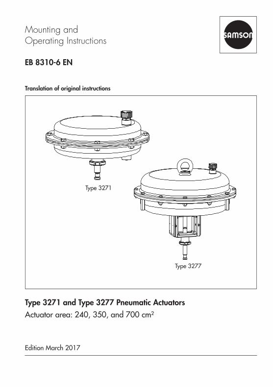
Translation of original instructions EB 8310-6 EN Mounting and Operating Instructions Edition March 2017 Type 3271 and Type 3277 Pneumatic Actuators Actuator area: 240, 350, and 700 cm² Type 3271 Type 3277
Transcript of Type 3271 and Type 3277 · Pneumatic Actuators - SAMSON · Type 3271 and Type 3277 Pneumatic...
Translation of original instructions
EB 8310-6 EN
Mounting and Operating Instructions
Edition March 2017
Type 3271 and Type 3277 Pneumatic ActuatorsActuator area: 240, 350, and 700 cm²
Type 3271
Type 3277

Note on these mounting and operating instructions
These mounting and operating instructions assist you in mounting and operating the device safely. The instructions are binding for handling SAMSON devices.
Î For the safe and proper use of these instructions, read them carefully and keep them for later reference.
Î If you have any questions about these instructions, contact SAMSON‘s After-sales Service Department ([email protected]).
The mounting and operating instructions for the devices are included in the scope of delivery. The latest documentation is available on our website at www.samson.de > Service & Support > Downloads > Documentation.
Definition of signal words
Hazardous situations which, if not avoided, will result in death or serious injury
Hazardous situations which, if not avoided, could result in death or serious injury
Property damage message or malfunction
Additional information
Recommended action
DANGER!
WARNING!
NOTICE!
Note
Tip
2 EB 8310-6 EN

Contents
EB 8310-6 EN 3
1 Safety instructions and measures ...................................................................51.1 Notes on possible severe personal injury .........................................................71.2 Notes on possible personal injury ...................................................................81.3 Notes on possible property damage ................................................................92 Markings on the device ...............................................................................102.1 Actuator nameplate ......................................................................................103 Design and principle of operation ................................................................113.1 Type 3271 ...................................................................................................113.2 Type 3277 ...................................................................................................123.3 Direction of action ........................................................................................133.4 Signal pressure routing .................................................................................133.4.1 Type 3271 ...................................................................................................133.4.2 Type 3277 ...................................................................................................133.5 Fail-safe action ............................................................................................133.5.1 Version with direction of action "actuator stem extends" (FA) ...........................143.5.2 Version with direction of action "actuator stem retracts" (FE) ............................143.6 Versions ......................................................................................................143.7 Technical data .............................................................................................154 Measures for preparation ............................................................................194.1 Unpacking ..................................................................................................194.2 Transporting and lifting ................................................................................194.2.1 Transporting ................................................................................................204.2.2 Lifting ..........................................................................................................204.3 Storage .......................................................................................................224.4 Preparation for installation ............................................................................235 Mounting and start-up .................................................................................245.1 Mounting the actuator onto the valve .............................................................245.2 Preloading the springs ..................................................................................275.2.1 Tensioning the springs ..................................................................................275.2.2 Increasing the actuator thrust ........................................................................275.2.3 Adapting the travel range .............................................................................28
Contents
4 EB 8310-6 EN
6 Operation ...................................................................................................306.1 Throttling service ..........................................................................................306.2 On/off service .............................................................................................306.3 Reversal of the direction of action ..................................................................316.3.1 Reversal of the direction of action from stem extends to stem retracts ................316.3.2 Reversal of the direction of action from stem retracts to stem extends ................336.4 Version with handwheel ................................................................................356.4.1 Extending the actuator stem manually ............................................................356.4.2 Retracting the actuator stem manually ............................................................356.5 Adjusting the travel stop ...............................................................................366.5.1 Bottom travel stop (minimum travel) ...............................................................366.5.2 Top travel stop (maximum travel) ...................................................................367 Servicing.....................................................................................................387.1 Replacing the diaphragm .............................................................................397.2 Replacing the actuator stem seals ..................................................................427.3 Preparation for return shipment .....................................................................447.4 Ordering spare parts and operating supplies .................................................458 Malfunctions ...............................................................................................469 Decommissioning and disassembly ..............................................................489.1 Decommissioning .........................................................................................489.2 Removing the actuator from the valve ............................................................489.3 Relieving the spring compression in the actuator .............................................489.4 Disposal ......................................................................................................4810 Annex.........................................................................................................5010.1 After-sales service ........................................................................................5010.2 Spare parts .................................................................................................51

EB 8310-6 EN 5
Safety instructions and measures
1 Safety instructions and measuresIntended useThe SAMSON Type 3271 and Type 3277 Actuators are designed for operating a mounted globe valve. In combination with the valve, the actuators are used to shut off the flow of liq-uids, gases or vapors in the pipeline. Depending on the version, the actuators are suitable for throttling or on/off service. The actuators can be used in processing and industrial plants.The actuators are designed to operate under exactly defined conditions (e.g. thrust, travel). Therefore, operators must ensure that the actuators are only used in applications that meet the specifications used for sizing the actuators at the ordering stage. In case operators intend to use the actuators in other applications or conditions than specified, contact SAMSON.SAMSON does not assume any liability for damage resulting from the failure to use the valve for its intended purpose or for damage caused by external forces or any other external factors.
Î Refer to the technical data and nameplate for limits and fields of application as well as possible uses.
Reasonably foreseeable misuseThe actuator is not suitable for the following applications: − Use outside the limits defined during sizing and in the technical data − Use outside the limits defined by the accessories mounted on the actuator
Furthermore, the following activities do not comply with the intended use: − Use of non-original spare parts − Performing service and repair work not described in these instructions
Qualifications of operating personnelThe actuator must be mounted, started up, serviced, and repaired by fully trained and quali-fied personnel only; the accepted industry codes and practices are to be observed. Accord-ing to these mounting and operating instructions, trained personnel refers to individuals who are able to judge the work they are assigned to and recognize possible hazards due to their specialized training, their knowledge and experience as well as their knowledge of the appli-cable standards.

6 EB 8310-6 EN
Safety instructions and measures
Personal protective equipmentWe recommend wearing the following personal protective equipment when handling the Type 3271 and Type 3277 Pneumatic Actuators: − Protective gloves when mounting or removing the actuator Î Check with the plant operator for details on further protective equipment.
Revisions and other modificationsRevisions, conversions or other modifications to the product are not authorized by SAMSON. They are performed at the user's own risk and may lead to safety hazards, for example. Fur-thermore, the product may no longer meet the requirements for its intended use.
Safety devicesThe Type 3271 and Type 3277 Actuators do not have any special safety equipment.
Warning against residual hazardsTo avoid personal injury or property damage, plant operators and operating personnel must prevent hazards that could be caused in the actuator by the process medium, the operating pressure, the signal pressure or by moving parts by taking appropriate precautions. They must observe all hazard statements, warning and caution notes in these mounting and oper-ating instructions, especially for installation, start-up, and service work.
Responsibilities of the operatorThe operator is responsible for proper operation and compliance with the safety regulations. Operators are obliged to provide these mounting and operating instructions as well as the referenced documents to the operating personnel and to instruct them in proper operation. Furthermore, the operator must ensure that operating personnel or third persons are not ex-posed to any danger.
Responsibilities of operating personnelOperating personnel must read and understand these mounting and operating instructions as well as the referenced documents and observe the hazard statements, warning and caution notes specified in them. Furthermore, the operating personnel must be familiar with the ap-plicable health, safety and accident prevention regulations and comply with them.

EB 8310-6 EN 7
Safety instructions and measures
Referenced standards and regulationsAccording to the ignition risk assessment performed in accordance with EN 13463-1:2009, section 5.2, the non-electrical actuators do not have their own potential ignition source even in the rare incident of an operating fault. As a result, they do not fall within the scope of Di-rective 2014/34/EU.
Î For connection to the equipotential bonding system, observe the requirements specified in section 6.4 of EN 60079-14 (VDE 0165 Part 1).
Referenced documentationThe following documents apply in addition to these mounting and operating instructions: − Mounting and operating instructions for the mounted valve − Mounting and operating instructions for mounted valve accessories (positioner, solenoid
valve etc.) − Safety Manual u SH 8310 for use in safety-instrumented systems − u AB 0100 for tools, tightening torques, and lubricant
1.1 Notes on possible severe personal injury
DANGER!
Risk of bursting in the actuator.Actuators are pressurized. Improper opening can lead to actuator components burst-ing.
Î Before starting any work on the actuator, depressurize all plant sections concerned and the actuator.

8 EB 8310-6 EN
Safety instructions and measures
1.2 Notes on possible personal injury
WARNING!
Crush hazard arising from moving parts.The actuator contains moving parts (actuator stem), which can injure hands or fingers if inserted into the actuator.
Î Do not insert hands or fingers into the yoke while the valve is in operation. Î While working on the actuator, disconnect and lock the pneumatic air supply as well as the control signal.
Risk of personal injury when the actuator vents.While the valve is operating, the actuator may vent during closed-loop control or when the valve opens or closes.
Î Install the control valve in such a way that the actuator does not vent at eye level. Î Use suitable silencers and vent plugs. Î Wear eye protection when working in close proximity to the control valve.
Risk of personal injury due to preloaded springs.Actuators with preloaded springs are under tension. They can be identified by the long bolts protruding from the bottom of the actuator.
Î Before starting any work on the actuator, relieve the compression from the preload-ed springs (see section 9.3).
Damage to health relating to the REACH regulation.If a SAMSON device contains a substance which is listed as being a substance of very high concern on the candidate list of the REACH regulation, this circumstance is indicat-ed on the SAMSON delivery note.
Î Information on safe use of the part affected, see u http://www.samson.de/reach-en.html.
EB 8310-6 EN 9
Safety instructions and measures
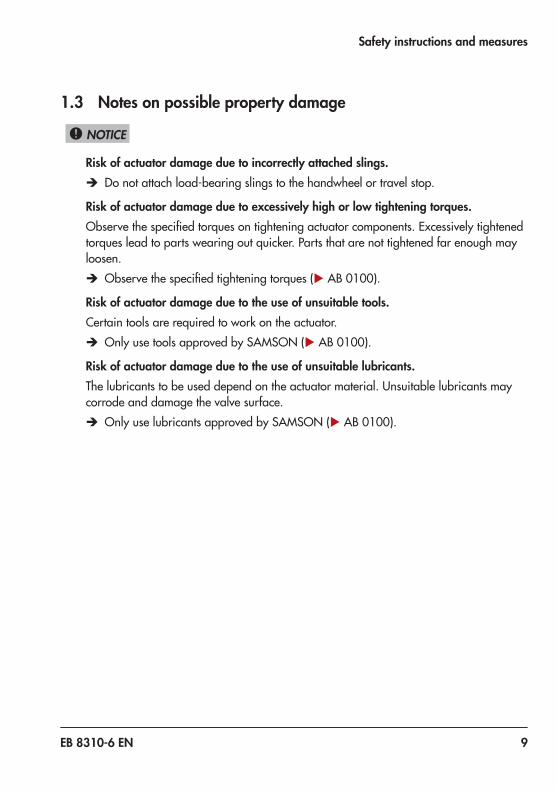
1.3 Notes on possible property damage
NOTICE!
Risk of actuator damage due to incorrectly attached slings. Î Do not attach load-bearing slings to the handwheel or travel stop.
Risk of actuator damage due to excessively high or low tightening torques.Observe the specified torques on tightening actuator components. Excessively tightened torques lead to parts wearing out quicker. Parts that are not tightened far enough may loosen.
Î Observe the specified tightening torques (u AB 0100).
Risk of actuator damage due to the use of unsuitable tools.Certain tools are required to work on the actuator.
Î Only use tools approved by SAMSON (u AB 0100).
Risk of actuator damage due to the use of unsuitable lubricants.The lubricants to be used depend on the actuator material. Unsuitable lubricants may corrode and damage the valve surface.
Î Only use lubricants approved by SAMSON (u AB 0100).

10 EB 8310-6 EN
Markings on the device
2 Markings on the device
2.1 Actuator nameplateThe nameplate is stuck on the diaphragm casing. It includes all details required to identify the device:
2 Configuration ID3 Serial number4 Actuator area5 Bench range in bar6 Bench range in psi7 Operating travel in mm8 Operating range in bar9 Operating range in psi
10 Permissible supply pressure pmax in bar11 Permissible supply pressure pmax in psi12 Symbol indicating fail-safe action
Actuator stem extends (FA)
Actuator stem retracts (FE)
Manual override
14 Connecting thread15 Diaphragm material16 Date of manufacture
7
4
14
15 12 65
89
10 11
SAMSON 3271Made in Germany
Var-ID3
2 Serial no.
16
Fig. 1: Nameplate of Type 3271 Actuator

EB 8310-6 EN 11
Design and principle of operation
3 Design and principle of oper-ation
The SAMSON Type 3271 and Type 3277 Actuators with 240. 350, and 700 cm² actu-ator areas are mounted to Series 240, 250, 280, and 290 Valves (globe valves).
3.1 Type 3271The actuator mainly consists of two dia-phragm cases (A1, A2), the diaphragm (A4) with diaphragm plate (A5), and springs (A10) (see Fig. 2).The signal pressure pst creates the force F = pst · A at the diaphragm surface A which is opposed by the springs (A10) in the actua-tor. The bench range is determined by the number of springs used and their compres-
A1 Top diaphragm case
A2 Bottom diaphragm case
A4 Diaphragm
A5 Diaphragm plateA7 Actuator stemA8 Ring nut
A10 SpringA16 Vent plug
A26/27 Stem connector clamp
S Signal pressure connection
Version with direction of action "actuator stem retracts" (FE)
Version with direction of action "actuator stem extends" (FA)S
A1
S
A4
A10
A7A8
A26/27
A16
A2
A5
Fig. 2: Type 3271 Pneumatic Actuator
12 EB 8310-6 EN
Design and principle of operation
sion, taking into account the rated travel. The travel is proportional to the signal pressure pst. The direction of action of the actuator stem (A7) depends on how the springs are installed in the actuator.A maximum of 12 springs (240 and 350 cm²) and a maximum of 18 springs (700 cm²), partly fitted into one another, can be installed in the actuator.The stem connector clamps (A26/27) con-nect the actuator stem (A7) with the plug stem of the globe valve.
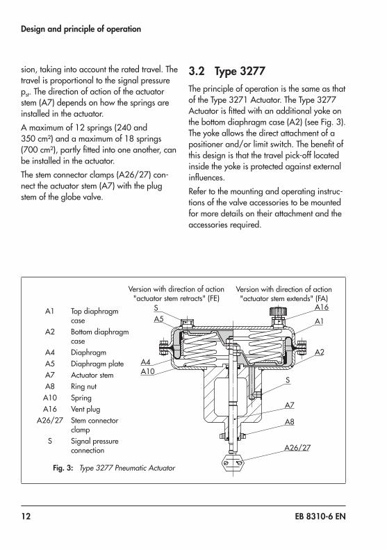
3.2 Type 3277The principle of operation is the same as that of the Type 3271 Actuator. The Type 3277 Actuator is fitted with an additional yoke on the bottom diaphragm case (A2) (see Fig. 3). The yoke allows the direct attachment of a positioner and/or limit switch. The benefit of this design is that the travel pick-off located inside the yoke is protected against external influences.Refer to the mounting and operating instruc-tions of the valve accessories to be mounted for more details on their attachment and the accessories required.
Fig. 3: Type 3277 Pneumatic Actuator
A1 Top diaphragm case
A2 Bottom diaphragm case
A4 DiaphragmA5 Diaphragm plateA7 Actuator stemA8 Ring nut
A10 SpringA16 Vent plug
A26/27 Stem connector clamp
S Signal pressure connection
Version with direction of action "actuator stem retracts" (FE)
Version with direction of action "actuator stem extends" (FA)
S
A1
S
A4A10
A7
A8
A26/27
A16
A2
A5

EB 8310-6 EN 13
Design and principle of operation
3.3 Direction of actionThe direction of action is determined by how the springs (A10) and diaphragm plate (A5) are arranged in the actuator.With direction of action "actuator stem ex-tends", the compressed air is applied to the signal pressure connection on the bottom di-aphragm case.With direction of action "actuator stem re-tracts", the compressed air is applied to the signal pressure connection on the top dia-phragm case.The actuator's direction of action can be re-versed (see section 6.3).
3.4 Signal pressure routing
3.4.1 Type 3271In the "actuator stem extends" version, the signal pressure is routed through the bottom signal pressure connection (S) to the bottom diaphragm chamber and moves the actuator stem (A7) upward opposing the spring force (see Fig. 2, right).In the "actuator stem retracts" version, the signal pressure is routed through the top sig-nal pressure connection (S) to the top dia-phragm chamber and moves the actuator stem (A7) downward opposing the spring force (see Fig. 2, left).
3.4.2 Type 3277In the "actuator stem extends" version, a sig-nal pressure connection (S) is located on the side of the yoke which is connected to the bottom diaphragm chamber over an internal hole (see Fig. 3, right). The signal pressure moves the actuator stem upward opposing the spring force. A positioner can be con-nected using a connection block at this point. No additional piping to the actuator is re-quired. Refer to the associated positioner documentation for more details.In the "actuator stem retracts" version, the signal pressure is routed through the top sig-nal pressure connection (S) to the top dia-phragm chamber and moves the actuator stem (A7) downward opposing the spring force (see Fig. 3, left).
3.5 Fail-safe actionWhen the signal pressure is reduced or the control signal fails, the fail-safe position of the control valve depends on whether the springs are installed in the top or bottom di-aphragm chamber.
The listed fail-safe actions apply to SAMSON Series 240, 250, 280 and 290 Valves (globe valves).
Note

14 EB 8310-6 EN
Design and principle of operation
3.5.1 Version with direction of action "actuator stem extends" (FA)
When the signal pressure is reduced or the control signal fails, the springs move the ac-tuator stem downward and close the globe valve. The valve opens when the signal pres-sure is increased enough to overcome the spring force.
3.5.2 Version with direction of action "actuator stem retracts" (FE)
When the signal pressure is reduced or the control signal fails, the springs move the ac-tuator stem upward and open a mounted globe valve. The valve closes when the signal pressure is increased enough to overcome the spring force.
3.6 VersionsThe Type 3271 and Type 3277 Pneumatic Actuators with 240, 350 or 700 cm² actua-tor area are available in the following ver-sions: − Standard version
The top and bottom diaphragm cases are made of painted sheet steel.
− Corrosion-resistant versionThe top and bottom diaphragm cases are made of stainless sheet steel (1.4301).
− Additional (top-mounted) handwheelThe actuators can be fitted with an addi-tional (top-mounted) handwheel (u T 8312).
− Travel stopThe actuators as a special version can be fitted with a mechanically adjustable travel stop. The travel is reduced by up to 50 % in both directions of action (stem extends or retracts).
− Side-mounted handwheelThe actuators can be combined with a Type 3273 Side-mounted Handwheel with max. 30 mm travel (u T 8312).

EB 8310-6 EN 15
Design and principle of operation
3.7 Technical dataThe nameplate provides information on the actuator version (see section 2.1).
More information is available in Data Sheet u T 8310-1.
Supply pressureThe maximum permissible supply pressure is 6 bar in throttling service. See section 6.2 for restrictions in on/off service.
Temperature rangeThe permissible temperature range depends on the actuator service and diaphragm ma-terial:
Diaphragm material Temperature rangeThrottling service
NBR –35 to +90 °C–31 to +194 °F
EPDM –50 to +120 °C–58 to +248 °F
On/off service
NBR –20 to +90 °C–4 to +194 °F
EPDM –40 to +120 °C–40 to +248 °F
ComplianceThe Type 3271 and Type 3277 Pneumatic Actuators bear the EAC mark of conformity.
Note
16 EB 8310-6 EN
Design and principle of operation
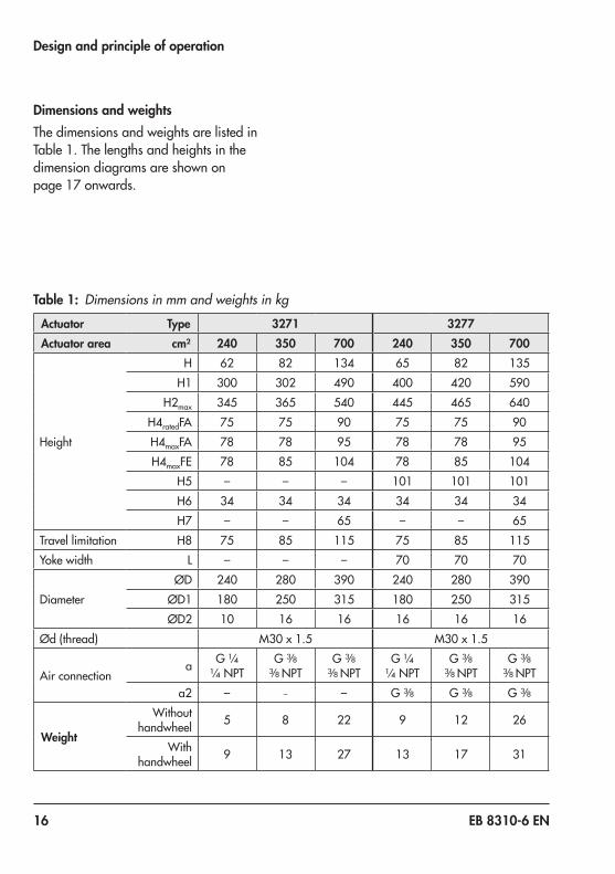
Dimensions and weightsThe dimensions and weights are listed in Table 1. The lengths and heights in the dimension diagrams are shown on page 17 onwards.
Table 1: Dimensions in mm and weights in kg
Actuator Type 3271 3277Actuator area cm² 240 350 700 240 350 700
Height
H 62 82 134 65 82 135H1 300 302 490 400 420 590
H2max 345 365 540 445 465 640H4ratedFA 75 75 90 75 75 90H4maxFA 78 78 95 78 78 95H4maxFE 78 85 104 78 85 104
H5 – – – 101 101 101H6 34 34 34 34 34 34H7 – – 65 – – 65
Travel limitation H8 75 85 115 75 85 115Yoke width L – – – 70 70 70
DiameterØD 240 280 390 240 280 390
ØD1 180 250 315 180 250 315ØD2 10 16 16 16 16 16
Ød (thread) M30 x 1.5 M30 x 1.5
Air connectiona G ¼
¼ NPTG 3/8
3/8 NPTG 3/8
3/8 NPTG ¼
¼ NPTG 3/8
3/8 NPTG 3/8
3/8 NPTa2 – – – G 3/8 G 3/8 G 3/8
Weight
Without handwheel 5 8 22 9 12 26
With handwheel 9 13 27 13 17 31

EB 8310-6 EN 17
Design and principle of operation
Dimensional drawings
a
a
HH6
H4
ØD
ØD2Ød
H7 H
a2
H5H4
H6
aØD
ØD2Ød
Standard version of Type 3271 (700 cm²) Standard version of Type 3277 (240, 350 cm²)
L
a
a
HH8
H6
H4
ØD
ØD2Ød
Type 3277 (side view) Type 3271 with travel stop

18 EB 8310-6 EN
Design and principle of operation
ØD1
ØD
ØD255
Ød
H
H1
H4H6H5
a2
H2
a
Type 3277 with handwheel

EB 8310-6 EN 19
Measures for preparation
4 Measures for preparationAfter receiving the shipment, proceed as fol-lows:1. Check the scope of delivery. Compare
the shipment received against the deliv-ery note.
2. Check the shipment for transportation damage. Report any damage to SAMSON and the forwarding agent (re-fer to delivery note).
4.1 Unpacking
Do not remove the packaging until immedi-ately before mounting.
Proceed as follows to lift and mount the actu-ator:1. Remove the packaging from the actuator.2. Dispose of the packaging in accordance
with the valid regulations.
4.2 Transporting and lifting
Hazard due to suspended loads falling.Stay clear of suspended or moving loads.
Risk of lifting equipment tipping and risk of damage to lifting accessories due to exceed-ing the rated lifting capacity. − Only use approved lifting equipment and accessories whose minimum lifting capaci-ty is higher than the weight of the actuator. − Refer to section 3.7 for weights.
Risk of actuator damage due to incorrectly attached slings. − The welded-on lifting eyelet on the top dia-phragm case is intended for mounting and removing the actuator as well as lifting the actuator without valve. Do not lift the entire control valve assembly using the lifting eyelet. − Do not attach load-bearing slings to the travel stop. − Observe lifting instructions (see sec-tion 4.2.2).
SAMSON's After-sales Service department can provide more detailed transport and lift-ing instructions on request.
Note
DANGER!
WARNING!
NOTICE!
Tip
20 EB 8310-6 EN
Measures for preparation
4.2.1 TransportingThe actuator can be transported using lifting equipment (e.g. crane or forklift).
Î Leave the actuator in its transport con-tainer or on the pallet to transport it.
Î Observe the transport instructions.
Transport instructions − Protect the actuator against external in-
fluences (e.g. impact). − Do not damage the corrosion protection
(paint, surface coatings). Repair any damage immediately.
− Protect the actuator against moisture and dirt.
− Observe permissible temperatures (see section 3.7).
4.2.2 LiftingTo mount a large actuator, use lifting equip-ment (e.g. crane or forklift) to lift it.
Lifting instructions − Secure slings against slipping. − Make sure the slings can be removed
from the actuator once it has been mounted onto the valve.
− Prevent the actuator from tilting or tip-ping.
− Do not leave loads suspended when in-terrupting work for longer periods of time.
− Make sure that the additional sling be-tween the lifting eyelet and rigging equipment (hook, shackle etc.) does not bear any load when lifting control valves larger than DN 150 with the actuator al-ready mounted. The sling only protects the control valve from tilting while being lifted. Before lifting the control valve, tighten the sling. The slings attached to the valve body must bear the entire load (see Fig. 5).

EB 8310-6 EN 21
Measures for preparation
Lifting the actuator (without valve)
Risk of actuator damage due to incorrectly attached slings.The welded-on lifting eyelet on the top dia-phragm case is intended for mounting and removing the actuator as well as lifting the actuator without valve. Do not lift the entire control valve assembly using the lifting eye-let.
1. Attach a sling to the lifting eyelet of the actuator and to the rigging equipment (e.g. hook) of the crane or forklift (see Fig. 4).
2. Carefully lift the actuator. Check whether the lifting equipment and accessories can bear the weight.
3. Move the actuator at an even pace to the mounting site.
4. Mount the actuator to the valve. See sec-tion 5.1.
5. Remove slings after mounting.
− We recommend using a hook with safety latch (see Fig. 4). The safety latch prevents the slings from slipping during lifting and transporting. − Special tools exist for lifting actuators with 240 and 350 cm² actuator areas (u AB 0100).
NOTICE!
Tip
Fig. 4: Lifting point on the actuator Fig. 5: Lifting points on the control valve (example)

22 EB 8310-6 EN
Measures for preparation
Lifting the entire control valve assembly Î See associated valve documentation for instructions on how to lift a control valve.
4.3 Storage
Risk of actuator damage due to improper storage. − Observe storage instructions. − Avoid long storage times. − Contact SAMSON in case of different stor-age conditions or long storage periods.
We recommend regularly checking the actu-ator and the prevailing storage conditions during long storage times.
Storage instructions − When the valve and actuator are al-
ready assembled, observe the storage conditions for control valves. See associ-ated valve documentation.
− Protect the actuator against external in-fluences (e.g. impact).
− Do not damage the corrosion protection (paint, surface coatings). Repair any damage immediately.
− Protect the actuator against moisture and dirt. Store it at a relative humidity of less than 75 %. In damp spaces, prevent con-densation. If necessary, use a drying agent or heating.
− Make sure that the ambient air is free of acids or other corrosive media.
− Observe permissible temperatures (see section 3.7).
− Do not place any objects on the actuator.
Special storage instructions for elastomersElastomer, e.g. actuator diaphragm − To keep elastomers in shape and to pre-
vent cracking, do not bend them or hang them up.
− We recommend a storage temperature of 15 °C for elastomers.
− Store elastomers away from lubricants, chemicals, solutions, and fuels.
SAMSON's After-sales Service department can provide more detailed storage instruc-tions on request.
NOTICE!
NoteTip

EB 8310-6 EN 23
Measures for preparation
4.4 Preparation for installationProceed as follows:
Î Check the actuator for damage. Î Check to make sure that the type desig-nation, material and temperature range of the actuator match the ambient condi-tions (temperatures etc.).
Î Check the pressure gauge installed on valve accessories to make sure it func-tions.
Î When the valve and actuator are al-ready assembled, check the tightening torques of the bolted joints (u AB 0100). Components may loosen during trans-port.

24 EB 8310-6 EN
Mounting and start-up
5 Mounting and start-upSAMSON control valves are delivered ready for use. In special cases, the valve and actu-ator are delivered separately and must be assembled on site. The procedure to mount and start up the actuator are described in following.
Risk of actuator damage due to excessively high or low tightening torques.Observe the specified torques on tightening actuator components. Excessively tightened torques lead to parts wearing out quicker. Parts that are not tightened far enough may loosen.Observe the specified tightening torques (u AB 0100).
Risk of actuator damage due to the use of unsuitable tools.Only use tools approved by SAMSON (u AB 0100).
See associated valve documentation for ad-ditional mounting instructions.
5.1 Mounting the actuator onto the valve
Proceed as follows if the valve and actuator have not been assembled by SAMSON:
− Remove the mounted actuator before mounting another actuator (see sec-tion 9.2). − Preloading the actuator springs increases the thrust and reduces the travel range of the actuator (see section 5.2).
The valve and actuator are assembled with special attention paid to the actuator's bench range and direction of action. These details are specified on the actuator nameplate (see section 2.1).
1. Loosen the lock nut (10) and stem con-nector nut (9) on the valve.
2. Press the plug together with the plug stem firmly into the seat ring.
3. Thread down the lock nut and stem con-nector nut.
4. Remove the clamps of the stem connector (A26/27) and the ring nut (A8) from the actuator.
5. Slide the ring nut over the plug stem.6. Place the actuator onto the valve bonnet
(2) and secure it with the ring nut.7. Determine the lower and upper signal
pressure range values:
NOTICE!
NOTICE!
Note
Note
Tip

EB 8310-6 EN 25
Mounting and start-up
2
849
108
A8A7
A26/27
a
x
2 Bonnet/flange8 Threaded bushing9 Stem connector nut10 Lock nut84 Travel indicator scaleA7 Actuator stem
A8 Ring nutA26/27 Stem connector clamps
Dimension a Refer to Table 2Dimension x Refer to Table 3
Fig. 6: Type 3271 Pneumatic Actuator mounted on globe valve

26 EB 8310-6 EN
Mounting and start-up
The lower signal pressure range value is the same as the minimum value of the bench range or operating range (with preloaded springs).The upper signal pressure range value is the same as the maximum value of the bench range or operating range (with preloaded springs).For actuator springs that are to be pre-loaded subsequently, determine the up-per and lower signal pressure range as described in section 5.2.
8. Depending on the direction of action:Actuator stem extendsApply a signal pressure that corresponds to the lower signal pressure range value to the connection on the bottom dia-phragm chamber.
Actuator stem retractsApply a signal pressure that corresponds to the upper signal pressure range value to the connection on the top diaphragm chamber.
9. Screw on the stem connector nut (9) by hand until it touches the actuator stem (A7).
10. Turn the stem connector nut a further quarter turn and secure this position with the lock nut (10).
11. Position clamps of the stem connector (A26/27) and screw them tight.
12. Make sure that the dimension a is adjusted as specified in Table 2.
13. Align the travel indicator (84) with the tip of the stem connector clamp.
Table 2: Values for dimension x 1) (see Fig. 6)
Actuator area Travel in mm Dimension a in mm
2400 (0 %) 75
15 (100 %) 6017 (112.5 %) 58
3500 (0 %) 75
15 (100 %) 6019 (125 %) 53
7000 (0 %) 90
30 (100 %) 6038 (125 %) 52
1) Type 3271: bottom edge of the bottom case to the top of the actuator stemType 3277: bottom edge of the bottom case to the top of the actuator stem

EB 8310-6 EN 27
Mounting and start-up
5.2 Preloading the springsBy preloading the springs in the actuator, the following can be achieved: − The thrust is increased (only actuators
with "stem extends") − In combination with a SAMSON valve:
the actuator travel range can be adapted to a smaller valve travel range
Actuators that have already been preloaded by SAMSON without mounting the valve are labeled correspondingly.Additionally, they can be identified by three longer bolts with nuts protruding from the bottom diaphragm case. They allow the spring compression to be relieved evenly when disassembling the actuator (see sec-tion 9.3).
5.2.1 Tensioning the springs
Risk of actuator damage due to the springs being tensioned unevenly. − Distribute clamping bolts and nuts evenly around the circumference. − Tighten the nuts gradually in a crisscross pattern.
1. Distribute the long bolts (A22) evenly around the circumference.
2. Screw the long nuts (A23) together with one washer (A25) onto the clamping
bolts (A22) until they rest on the bottom diaphragm case (A2).
3. To tension the springs evenly, tighten the nuts (A23) gradually in a crisscross pat-tern until both diaphragm cases (A1, A2) rest on the diaphragm (A4). Hold the bold head stationary with a suitable tool and apply the tightening torque to the nuts. Observe tightening torques.
4. Insert the short bolts (A20) through the intended holes on the diaphragm cases (A1, A2).
5. Screw the short nuts (A21) with washers (A25) onto the bolts (A20). Observe tightening torques.
5.2.2 Increasing the actuator thrust
The thrust can only be increased in actuators with "stem extends" direction of action. To achieve this, the springs of the actuators can be preloaded by up to 12.5 % (240 cm²) or by up to 25 % (350 and 700 cm²) of their travel or bench range.Example: Preloading is required for a bench range of 0.4 to 2 bar. 25 % of this span cor-responds to 0.4 bar. Therefore, the signal pressure range is shifted by 0.4 bar to 0.8 to 2.4 bar. The new lower signal pressure range value is 0.8 bar and the new upper signal pressure range value 2.4 bar.
Î Write the new signal pressure range of 0.8 to 2.4 bar on the actuator nameplate as the operating range with preloaded springs.
Note
NOTICE!
28 EB 8310-6 EN
Mounting and start-up
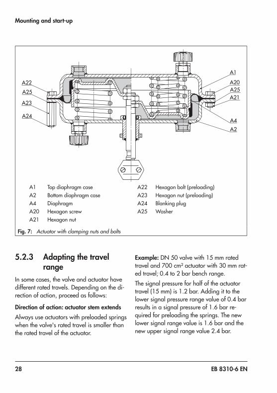
A1 Top diaphragm caseA2 Bottom diaphragm caseA4 DiaphragmA20 Hexagon screwA21 Hexagon nut
A22 Hexagon bolt (preloading)A23 Hexagon nut (preloading)A24 Blanking plugA25 Washer
A22
A23
A25
A24
A20A25A21
A1
A2A4
Fig. 7: Actuator with clamping nuts and bolts
5.2.3 Adapting the travel range
In some cases, the valve and actuator have different rated travels. Depending on the di-rection of action, proceed as follows:
Direction of action: actuator stem extendsAlways use actuators with preloaded springs when the valve's rated travel is smaller than the rated travel of the actuator.
Example: DN 50 valve with 15 mm rated travel and 700 cm² actuator with 30 mm rat-ed travel; 0.4 to 2 bar bench range.The signal pressure for half of the actuator travel (15 mm) is 1.2 bar. Adding it to the lower signal pressure range value of 0.4 bar results in a signal pressure of 1.6 bar re-quired for preloading the springs. The new lower signal range value is 1.6 bar and the new upper signal range value 2.4 bar.

EB 8310-6 EN 29
Mounting and start-up
Î Write the new signal pressure range of 1.6 to 2.4 bar on the actuator nameplate as the operating range with preloaded springs.
Direction of action: actuator stem retractsThe springs of actuators with "stem retracts" action cannot be preloaded. When a SAMSON valve is combined with an over-sized actuator (e.g. the rated travel of the actuator is larger than the rated travel of the valve), only the first half of the actuator's bench range can be used.Example: DN 50 valve with 15 mm rated travel and 700 cm² actuator with 30 mm rat-ed travel; 0.2 to 1 bar bench range.At half the valve travel, the operating range is between 0.2 and 0.6 bar.

30 EB 8310-6 EN
Operation
6 Operation
Crush hazard arising from moving parts.The actuator contains moving parts (actuator stem), which can injure hands or fingers if inserted into the actuator. − Do not insert hands or fingers into the yoke while the valve is in operation. − While working on the actuator, disconnect and lock the pneumatic air supply as well as the control signal.
Risk of personal injury when the actuator vents.Wear eye protection when working in close proximity to the control valve.
Operating disturbed by a blocked actuator stem.Do not impede the movement of the actuator stem by inserting objects into its path.
6.1 Throttling serviceThe Types 3271 and Type 3277 Pneumatic Actuators with 240, 350, and 700 cm² actu-ator areas are designed for a maximum sup-ply pressure of 6 bar when used for throt-tling service.
6.2 On/off serviceIn on/off service, the supply pressure must be limited depending on the bench range or operating range of the actuator. The applica-ble bench range or operating range which the actuator can move through is written on the nameplate (see section 2.1).
Actuator stem retracts (FE)For the direction of action "actuator stem re-tracts (FE)", the permissible supply pressure must not exceed the upper bench range val-ue by more than 3 bar:
Bench range Fail-safe ac-tion
Max. sup-ply pres-
sure
0.2 to 1.0 barActuator stem
retracts
4 bar
0.4 to 2.0 bar 5 bar
0.6 to 3.0 bar 6 bar
Actuator stem extends (FA)With fail-safe action "actuator stem extends" and travel stop, the supply pressure must not exceed the upper spring range value by more than 1.5 bar.
Additional points that apply concerning op-eration:
Î Label actuator with reduced supply pres-sure with a sticker ("Max. supply pres-sure limited to ... bar").
Î Only apply the signal pressure to the sig-nal pressure connection (S) on the dia-phragm chamber of the actuator which does not contain any springs (see Fig. 3).
WARNING!
WARNING!
NOTICE!

EB 8310-6 EN 31
Operation
Î Only use vent plugs that let air through them (A16 in Fig. 3).
6.3 Reversal of the direction of action
The direction of action (and fail-safe action) of pneumatic actuators can be changed. The fail-safe action is indicated on the nameplate by a symbol:
Actuator stem extends
Actuator stem retracts
Risk of bursting in the actuator.Actuators are pressurized. Improper opening can lead to actuator components bursting.Before starting any work on the actuator, de-pressurize all plant sections concerned and the actuator.
Risk of personal injury due to preloaded springs.Actuators with preloaded springs are under tension. They can be identified by three long bolts protruding from the bottom of the actu-ator.Before starting any work on the actuator, re-lieve the compression from the preloaded springs (see section 9.3).
Risk of malfunction due to incorrect details on the nameplate after the reversal of the direction of action.After reversal, the symbol and configuration ID on the nameplate are no longer valid. Contact SAMSON to request a new name-plate.
6.3.1 Reversal of the direction of action from stem ex-tends to stem retracts
1. Lift the actuator off the valve. See sec-tion 9.2.
2. Unscrew the nuts (A21) and bolts (A20) on the diaphragm case.
3. Relieve the spring compression of actua-tors with preloaded springs (see sec-tion 9.3).
4. Lift off the top diaphragm case (A1) and remove springs (A10).
5. Pull the diaphragm plate assembly con-sisting of the diaphragm plate (A5), dia-phragm (A4), and actuator stem (A7) out of the bottom diaphragm case (A2).
6. Clamp the bottom section of the actuator stem (A7) into a vise using protective jaws. Make sure that the actuator stem is not damaged.
7. Unscrew and remove the collar nut (A15), while holding the nut (A9) station-ary.
DANGER!
WARNING!
NOTICE!

32 EB 8310-6 EN
Operation
Malfunction due to loosened nut.The nut (A9) on the actuator stem serves to adjust the dimension x. Do not undo the nut. If the nut has come undone, readjust the di-mension x as specified in Table 3.
8. Remove the diaphragm plate (A5) with diaphragm (A4) from the actuator stem and place them back on in reverse order.
9. Tighten the collar nut (A15), while hold-ing the nut (A9) stationary. Observe tightening torques.
10. Apply a suitable lubricant to the actuator stem (A7).
11. Clamp the top diaphragm case (A1) with the opening facing upward into a suit-able clamping fixture.
12. Place the diaphragm plate assembly to-gether with the actuator stem (A7) point-ing upward into the diaphragm case (A1).
13. Place the springs (A10) in the diaphragm plate (A5), centering them in the intend-ed recesses.
14. Carefully guide the bottom diaphragm case (A2) over the actuator stem (A7) and place it on the springs (A10). Make sure that the sealing elements are not damaged. Ensure that the compressed air connections on the cases (A1, A2) are correctly aligned with each other.
15. Fasten the top and bottom diaphragm cases (A1, A2) together using the nuts (A21) and bolts (A20). Observe tighten-ing torques.
NOTICE!
X
A4
A6
A19
A15A5
A9A7
A6
A19
A4 A15A5
A9A7
X
A4 DiaphragmA5 Diaphragm plateA6 Hose clampA7 Actuator stem
A9 Hexagon nutA15 Collar nutA19 Compressor
Fig. 8: Arrangement of parts for "stem retracts" direction of action (left) and "stem extends" direction of action (right)

EB 8310-6 EN 33
Operation
16. Unscrew the vent plug (A16) from the top signal pressure connection and screw it into the bottom connection (S).The actuator springs, which now push against the diaphragm plate from below, cause the actuator stem to retract. The signal pressure is connected to the top connection (S) on the top diaphragm case. As a result, the actuator stem ex-tends opposing the spring force as the signal pressure increases.
17. Affix a new nameplate with changed symbol and new configuration ID to the actuator.
6.3.2 Reversal of the direction of action from stem re-tracts to stem extends
1. Lift the actuator off the valve. See sec-tion 9.2.
2. Unscrew the nuts (A21) and bolts (A20) on the diaphragm case.
3. Lift off the top diaphragm case (A1).
4. Pull the diaphragm plate assembly con-sisting of the diaphragm plate (A5), dia-phragm (A4), and actuator stem (A7) out of the actuator.
5. Take the springs (A10) out of the bottom diaphragm case (A2).
6. Unscrew and remove the collar nut (A15), while holding the nut (A9) station-ary.
Malfunction due to loosened nut.The nut (A9) on the actuator stem serves to adjust the dimension x. Do not undo the nut. If the nut has come undone, readjust the di-mension x as specified in Table 3.
7. Clamp the bottom section of the actuator stem (A7) into a vise using protective jaws. Make sure that the actuator stem is not damaged.
8. Remove the diaphragm plate (A5) with diaphragm (A4) from the actuator stem and place them back on in reverse order.
NOTICE!
Table 3: Values for dimension x (see Fig. 8)
Type Actuator area Travel in mm Dimension x in mm(top of the nut to the bottom of the actuator stem)
3271240 15 98.25350 15 107.25700 30 144
3277240 15 –350 15 209700 30 246

34 EB 8310-6 EN
Operation
9. Tighten the collar nut (A15), while hold-ing the nut (A9) stationary. Observe tightening torques.
10. Apply a suitable lubricant to the actuator stem (A7).
11. Place the diaphragm plate assembly to-gether with the actuator stem (A7) point-ing downward into the bottom dia-phragm case (A2). Make sure that the sealing elements are not damaged.
12. Place the springs (A10) into the bottom diaphragm case, centering them in the intended recesses.
13. Place on the top diaphragm case (A1).14. If necessary, preload the springs (see
section 5.2).15. Fasten the top and bottom diaphragm
cases (A1, A2) together using the nuts (A21) and bolts (A20). Observe tighten-ing torques.
16. Unscrew the vent plug (A16) from the bottom signal pressure connection and screw it into the top connection (S).The actuator springs, which now push against the diaphragm plate from above, cause the actuator stem to extend. The signal pressure is connected to the bottom connection (S) on the bottom diaphragm case. As a result, the actuator stem retracts opposing the spring force as the signal pressure increases.
17. Affix a new nameplate with changed symbol and new configuration ID to the actuator.
EB 8310-6 EN 35
Operation
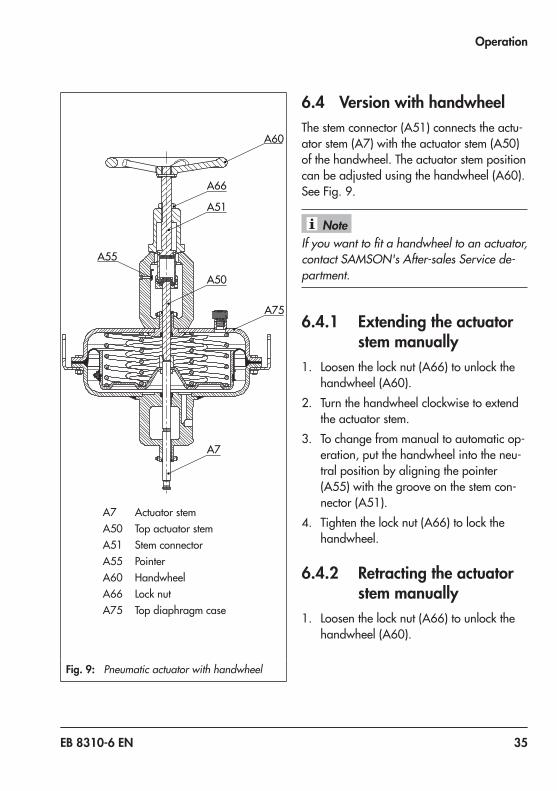
A7 Actuator stemA50 Top actuator stemA51 Stem connectorA55 PointerA60 HandwheelA66 Lock nutA75 Top diaphragm case
A60
A66
A51
A50
A75
A55
A7
Fig. 9: Pneumatic actuator with handwheel
6.4 Version with handwheelThe stem connector (A51) connects the actu-ator stem (A7) with the actuator stem (A50) of the handwheel. The actuator stem position can be adjusted using the handwheel (A60). See Fig. 9.
If you want to fit a handwheel to an actuator, contact SAMSON's After-sales Service de-partment.
6.4.1 Extending the actuator stem manually
1. Loosen the lock nut (A66) to unlock the handwheel (A60).
2. Turn the handwheel clockwise to extend the actuator stem.
3. To change from manual to automatic op-eration, put the handwheel into the neu-tral position by aligning the pointer (A55) with the groove on the stem con-nector (A51).
4. Tighten the lock nut (A66) to lock the handwheel.
6.4.2 Retracting the actuator stem manually
1. Loosen the lock nut (A66) to unlock the handwheel (A60).
Note

36 EB 8310-6 EN
Operation
2. Turn the handwheel counterclockwise to retract the actuator stem.
3. To change from manual to automatic op-eration, put the handwheel into the neu-tral position by aligning the pointer (A55) with the groove on the stem con-nector (A51).
4. Tighten the lock nut (A66) to lock the handwheel.
6.5 Adjusting the travel stopIn the version with travel stop, the maximum and minimum actuator travel can be limited as follows:
Direction of action
Min. stop Max. stop
Stem extends (FA)
0 to 125 % 50 to 125 %
Stem retracts (FE)
0 to 100 % 50 to 100 %
6.5.1 Bottom travel stop (min-imum travel)
1. Loosen top lock nut (A74) and unscrew cover (A73).
2. Loosen bottom lock nut (A74) and turn the adjustment nut (A70) to adjust the travel stop.
3. Tighten bottom lock nut (A74).4. Attach the cover (A73) and retighten the
lock nut (A74).
6.5.2 Top travel stop (maximum travel)
1. Loosen top lock nut (A74).2. Adjust the cover (A73) to the required
travel stop.3. Retighten top lock nut (A74).

EB 8310-6 EN 37
Operation
Left half: Actuator stem retracts (FE)Right half: Actuator stem extends (FA) A73
A74
A70
A75
A5A7
A50
A5 Diaphragm plateA7 Actuator stem
A50 Top actuator stemA70 Adjustment nut
A73 CoverA74 Lock nutA75 Top diaphragm case
Fig. 10: Travel stop
38 EB 8310-6 EN
Servicing
7 Servicing
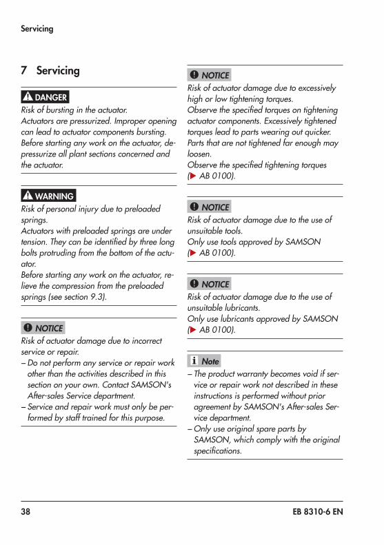
Risk of bursting in the actuator.Actuators are pressurized. Improper opening can lead to actuator components bursting.Before starting any work on the actuator, de-pressurize all plant sections concerned and the actuator.
Risk of personal injury due to preloaded springs.Actuators with preloaded springs are under tension. They can be identified by three long bolts protruding from the bottom of the actu-ator.Before starting any work on the actuator, re-lieve the compression from the preloaded springs (see section 9.3).
Risk of actuator damage due to incorrect service or repair. − Do not perform any service or repair work other than the activities described in this section on your own. Contact SAMSON's After-sales Service department. − Service and repair work must only be per-formed by staff trained for this purpose.
Risk of actuator damage due to excessively high or low tightening torques.Observe the specified torques on tightening actuator components. Excessively tightened torques lead to parts wearing out quicker. Parts that are not tightened far enough may loosen.Observe the specified tightening torques (u AB 0100).
Risk of actuator damage due to the use of unsuitable tools.Only use tools approved by SAMSON (u AB 0100).
Risk of actuator damage due to the use of unsuitable lubricants.Only use lubricants approved by SAMSON (u AB 0100).
− The product warranty becomes void if ser-vice or repair work not described in these instructions is performed without prior agreement by SAMSON's After-sales Ser-vice department. − Only use original spare parts by SAMSON, which comply with the original specifications.
DANGER!
WARNING!
NOTICE!
NOTICE!
NOTICE!
NOTICE!
Note

EB 8310-6 EN 39
Servicing
7.1 Replacing the diaphragm
Risk of malfunction due to damaged hose clamp.Do not reuse hose clamps. Use a new hose clamp every time the diaphragm is replaced.
Risk of property damage and malfunction due to incorrect mounting of the hose clamp.Tighten the hose clamp using a torque wrench and use a special tool to position it centrically.
Version with direction of action "actuator stem extends" (FA)1. Lift the actuator off the valve. See sec-
tion 9.2.2. Unscrew the nuts (A21) and bolts (A20)
on the diaphragm case.
3. Relieve the spring compression of actua-tors with preloaded springs (see sec-tion 9.3).
4. Lift off the top diaphragm case (A1) and remove springs (A10).
5. Pull the diaphragm plate assembly con-sisting of the diaphragm plate (A5), dia-phragm (A4), and actuator stem (A7) out of the bottom diaphragm case (A2).
6. Clamp the bottom section of the actuator stem (A7) into a vise using protective jaws. Make sure that the actuator stem is not damaged.
7. 240 cm²: undo the latch of the hose clamp (A6). Take the hose clamp (A6) and diaphragm (A4) off the diaphragm plate (A5).350 and 700 cm²: undo the latch of the hose clamp (A6). Take the compressor (A19), hose clamp (A6), and diaphragm (A4) off the diaphragm plate (A5).
NOTICE!
NOTICE!
A4 DiaphragmA5 Diaphragm plateA6 Hose clampA7 Actuator stemA9 Hexagon nutA15 Collar nutA19 Compressor on the hose
clamp (A6)
A4
A6
A19
A15A5
A9A7
Fig. 11: Arrangement of parts for "stem extends" direction of action
40 EB 8310-6 EN
Servicing
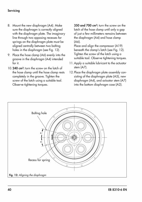
8. Mount the new diaphragm (A4). Make sure the diaphragm is correctly aligned with the diaphragm plate. The imaginary line through two opposing recesses for springs on the diaphragm plate must be aligned centrally between two bolting holes in the diaphragm (see Fig. 12).
9. Place the hose clamp (A6) evenly into the groove in the diaphragm (A4) intended for it.
10. 240 cm²: turn the screw on the latch of the hose clamp until the hose clamp rests completely in the groove. Tighten the screw of the latch using a suitable tool. Observe tightening torques.
350 and 700 cm²: turn the screw on the latch of the hose clamp until only a gap of just a few millimeters remains between the diaphragm (A4) and hose clamp (A6).Place and align the compressor (A19) beneath the clamp's latch (see Fig. 12).Tighten the screw of the latch using a suitable tool. Observe tightening torques.
11. Apply a suitable lubricant to the actuator stem (A7).
12. Place the diaphragm plate assembly con-sisting of the diaphragm plate (A5), new diaphragm (A4), and actuator stem (A7) into the bottom diaphragm case (A2).
==
Recess for spring
Bolting hole
Fig. 12: Aligning the diaphragm

EB 8310-6 EN 41
Servicing
Make sure that the sealing elements are not damaged.
13. Place the springs (A10) into the bottom diaphragm case, centering them in the intended recesses.
14. Place on the top diaphragm case (A1).15. If necessary, preload the springs (see
section 5.2).16. Fasten the top and bottom diaphragm
cases (A1, A2) together using the nuts (A21) and bolts (A20). Observe tighten-ing torques.
17. Mount the actuator on the valve (see sec-tion 5.1).
Version with direction of action "actuator stem retracts" (FE)1. Lift the actuator off the valve. See sec-
tion 9.2.2. Unscrew the nuts (A21) and bolts (A20)
on the diaphragm case.3. Lift off the top diaphragm case (A1).
4. Pull the diaphragm plate assembly con-sisting of the diaphragm plate (A5), dia-phragm (A4), and actuator stem (A7) out of the actuator.
5. Take the springs (A10) out of the bottom diaphragm case (A2).
6. Clamp the bottom section of the actuator stem (A7) into a vise using protective jaws. Make sure that the actuator stem is not damaged.
7. 240 cm²: undo the latch of the hose clamp (A6). Take the hose clamp (A6) and diaphragm (A4) off the diaphragm plate (A5).350 and 700 cm²: undo the latch of the hose clamp (A6). Take the compressor (A19), hose clamp (A6), and diaphragm (A4) off the diaphragm plate (A5).
8. Mount the new diaphragm (A4). Make sure the diaphragm is correctly aligned with the diaphragm plate. The imaginary line through two opposing recesses for springs on the diaphragm plate must be
A4 DiaphragmA5 Diaphragm plateA6 Hose clampA7 Actuator stemA9 Hexagon nutA15 Collar nutA19 Compressor on the hose
clamp (A6)
A6
A19
A4 A15A5
A9A7
Fig. 13: Arrangement of parts for "stem retracts" direction of action
42 EB 8310-6 EN
Servicing
aligned centrally between two bolting holes in the diaphragm (see Fig. 12).
9. Place the hose clamp (A6) evenly into the groove in the diaphragm (A4) intended for it.
10. 240 cm²: turn the screw on the latch of the hose clamp until the hose clamp rests completely in the groove. Tighten the screw of the latch using a suitable tool. Observe tightening torques.350 and 700 cm²: turn the screw on the latch of the hose clamp until only a gap of just a few millimeters remains between the diaphragm (A4) and hose clamp (A6).Place and align the compressor (A19) beneath the clamp's latch (see Fig. 12).Tighten the screw of the latch using a suitable tool. Observe tightening torques.
11. Apply a suitable lubricant to the actuator stem (A7).
12. Clamp the top diaphragm case (A1) with the opening facing upward into a suit-able clamping fixture.
13. Place the diaphragm plate assembly con-sisting of the diaphragm plate (A5), new diaphragm (A4), and actuator stem (A7) with the actuator stem pointing upward into the diaphragm case (A1).
14. Place the springs (A10) in the diaphragm plate (A5), centering them in the intend-ed recesses.
15. Carefully guide the bottom diaphragm case (A2) over the actuator stem (A7) and place it on the springs (A10). Make sure that the sealing elements are not
damaged. Ensure that the compressed air connections on the cases (A1, A2) are correctly aligned with each other.
16. Fasten the top and bottom diaphragm cases (A1, A2) together using the nuts (A21) and bolts (A20). Observe tighten-ing torques.
17. Mount the actuator on the valve (see sec-tion 5.1).
7.2 Replacing the actuator stem seals
Version with direction of action "actuator stem extends" (FA)1. Lift the actuator off the valve. See sec-
tion 9.2.2. Unscrew the nuts (A21) and bolts (A20)
on the diaphragm case.3. Relieve the spring compression of actua-
tors with preloaded springs (see sec-tion 9.3).
4. Lift off the top diaphragm case (A1) and remove springs (A10).
5. Pull the diaphragm plate assembly con-sisting of the diaphragm plate (A5), dia-phragm (A4), and actuator stem (A7) out of the bottom diaphragm case (A2).
6. Use a suitable punch to remove the radi-al shaft seal (A40).
7. Apply a suitable lubricant to the new ra-dial shaft seal (A40).
8. Use a suitable mandrel to mount the ra-dial shaft seal (A40).

EB 8310-6 EN 43
Servicing
A42A41
A40A42
A40A42
A7
A41
A7 Actuator stemA40 Radial shaft sealA41 WiperA42 Dry bearing
Type 3271
Type 3277
Fig. 14: Actuator stem seals
9. Renew the dry bearing (A42) and wiper (A41), if necessary.
10. Apply a suitable lubricant to the actuator stem (A7).
11. Place the diaphragm plate assembly con-sisting of the diaphragm plate (A5), new diaphragm (A4), and actuator stem (A7) into the bottom diaphragm case (A2). Make sure that the sealing elements are not damaged. Ensure that the com-pressed air connections on the cases (A1, A2) are correctly aligned with each other.
12. Place the springs (A10) into the bottom diaphragm case, centering them in the intended recesses.
13. Place on the top diaphragm case (A1).14. If necessary, preload the springs (see
section 5.2).15. Fasten the top and bottom diaphragm
cases (A1, A2) together using the nuts (A21) and bolts (A20). Observe tighten-ing torques.
16. Mount the actuator on the valve (see sec-tion 5.1).
Version with direction of action "actuator stem retracts" (FE)1. Lift the actuator off the valve. See sec-
tion 9.2.2. Unscrew the nuts (A21) and bolts (A20)
on the diaphragm case.3. Lift off the top diaphragm case (A1).4. Pull the diaphragm plate assembly con-
sisting of the diaphragm plate (A5), dia-

44 EB 8310-6 EN
Servicing
phragm (A4), and actuator stem (A7) out of the actuator.
5. Take the springs (A10) out of the bottom diaphragm case (A2).
6. Use a suitable punch to remove the radi-al shaft seal.
7. Apply a suitable lubricant to the new ra-dial shaft seal (A40).
8. Use a suitable mandrel to mount the ra-dial shaft seal (A40).
9. Renew the dry bearing (A42) and wiper (A41), if necessary.
10. Apply a suitable lubricant to the actuator stem (A7).
11. Clamp the top diaphragm case (A1) with the opening facing upward into a suit-able clamping fixture.
12. Place the diaphragm plate assembly to-gether with the actuator stem (A7) point-ing upward into the diaphragm case (A1).
13. Place the springs (A10) in the diaphragm plate (A5), centering them in the intend-ed recesses.
14. Carefully guide the bottom diaphragm case (A2) over the actuator stem (A7) and place it on the springs (A10). Make sure that the sealing elements are not damaged. Ensure that the compressed air connections on the cases (A1, A2) are correctly aligned with each other.
15. Fasten the top and bottom diaphragm cases (A1, A2) together using the nuts (A21) and bolts (A20). Observe tighten-ing torques.
16. Mount the actuator on the valve (see sec-tion 5.1).
7.3 Preparation for return ship-ment
Defective actuators can be returned to SAMSON for repair.Proceed as follows to return valves to SAMSON:1. Put the control valve out of operation.
See associated valve documentation.2. Lift the actuator off the valve. See sec-
tion 9.2.3. If necessary, relieve the spring compres-
sion (see section 9.3).4. Send the actuator to your nearest
SAMSON subsidiary. SAMSON subsid-iaries are listed on our website at u www.samson.de > Contact.

EB 8310-6 EN 45
Servicing
7.4 Ordering spare parts and operating supplies
Contact your nearest SAMSON subsidiary or the SAMSON After-sales Service depart-ment for information on spare parts, lubri-cants, and tools.
Spare partsSee section 10.2 for details on spare parts.
LubricantDetails on suitable lubricants can be found in the document u AB 0100.
ToolsDetails on suitable tools can be found in the document u AB 0100.

46 EB 8310-6 EN
Malfunctions
8 MalfunctionsDepending on the operating conditions, check the actuator at certain intervals to prevent possible failure before it can occur. Operators are responsible for drawing up an inspection plan.
Troubleshooting
Malfunction Possible reasons Recommended actionActuator stem does not move on demand.
Actuator is blocked. Check attachment.Unblock the actuator.
Insufficient signal pressure Check the signal pressure.Check the signal pressure line for leakage.
Signal pressure not connected to the correct diaphragm chamber.
See section 3.4.
Actuator stem does not stroke through its complete travel range.
Travel stop active See section 6.5.
Insufficient signal pressure Check the signal pressure.Check the signal pressure line for leakage.
Valve accessories incorrectly set. Check the actuator without valve accessories.Check the settings of the valve accessories.

EB 8310-6 EN 47

48 EB 8310-6 EN
Decommissioning and disassembly
9 Decommissioning and disas-sembly
Risk of bursting in the actuator.Actuators are pressurized. Improper opening can lead to actuator components bursting.Before starting any work on the actuator, de-pressurize all plant sections concerned and the actuator.
Risk of personal injury due to preloaded springs.Actuators with preloaded springs are under tension. They can be identified by three long bolts protruding from the bottom of the actu-ator.Before starting any work on the actuator, re-lieve the compression from the preloaded springs (see section 9.3).
9.1 DecommissioningTo decommission the actuator for service and repair work or disassembly, proceed as fol-lows:1. Put the control valve out of operation.
See associated valve documentation.2. Disconnect the pneumatic air supply to
depressurize the actuator.
9.2 Removing the actuator from the valve
1. Put the control valve out of operation. See associated valve documentation.
2. Undo the clamps of the stem connector (A26/27).
3. Loosen the stem connector nut (9) and lock nut (10).
4. Removing actuators with "stem ex-tends" action with/without preloaded springs: to undo the ring nut (A8), apply approx. 50 % signal pressure to open the valve.
5. Unscrew the ring nut on the valve bonnet.6. Disconnect the signal pressure again.7. Separate the actuator from the valve by
undoing the ring nut.8. Fasten the lock nut and stem connector
nut on the valve.
9.3 Relieving the spring com-pression in the actuator
1. Undo the short nuts (A21) and bolts (A20) on the diaphragm cases (A1, A2).
2. Undo the the long nuts (A23) and bolts (A22) on the diaphragm cases evenly in a crisscross pattern.
9.4 Disposal Î Observe local, national, and internation-al refuse regulations.
Î Do not dispose of components, lubri-cants, and hazardous substances togeth-er with your other household waste.
DANGER!
WARNING!

EB 8310-6 EN 49
Decommissioning and disassembly
A1 Top diaphragm caseA2 Bottom diaphragm caseA4 DiaphragmA20 Hexagon screwA21 Hexagon nut
A22 Hexagon bolt (preloading)A23 Hexagon nut (preloading)A24 Blanking plugA25 Washer
A22
A23
A25
A24
A20A25A21
A1
A2A4
Fig. 15: Actuator with clamping nuts and bolts

50 EB 8310-6 EN
Annex
10 Annex
10.1 After-sales serviceContact SAMSON's After-sales Service de-partment for support concerning service or repair work or when malfunctions or defects arise.
E-mailYou can reach the After-sales Service De-partment at [email protected].
Addresses of SAMSON AG and its subsid-iariesThe addresses of SAMSON AG, its subsid-iaries, representatives and service facilities worldwide can be found on the SAMSON website, in all SAMSON product catalogs or on the back of these Mounting and Operat-ing Instructions.
Required specificationsPlease submit the following details: − Order number and position number in
the order − Type, model number, actuator area, trav-
el, direction of action and bench range (e.g. 0.2 to 1 bar) or the operating range of the actuator
− Type designation of mounted valve (if applicable)
− Installation drawing

EB 8310-6 EN 51
Annex
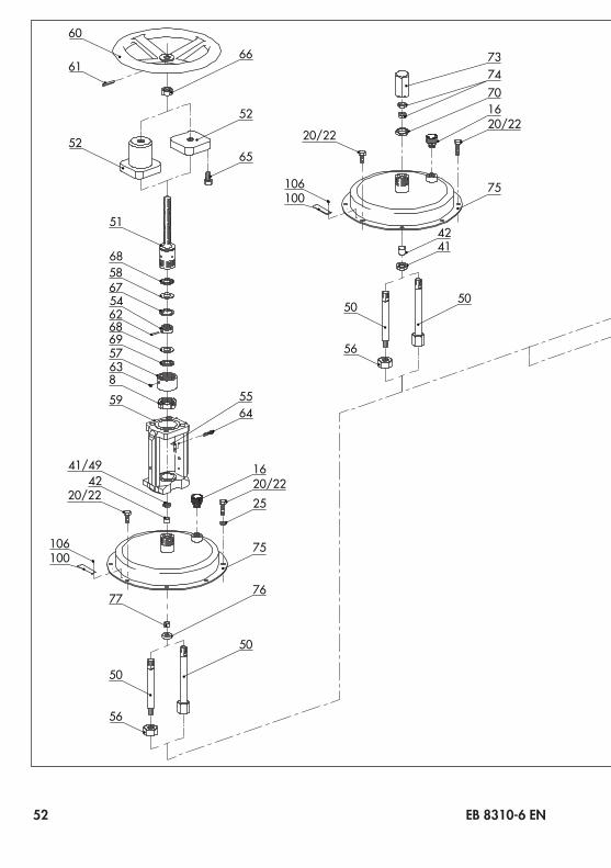
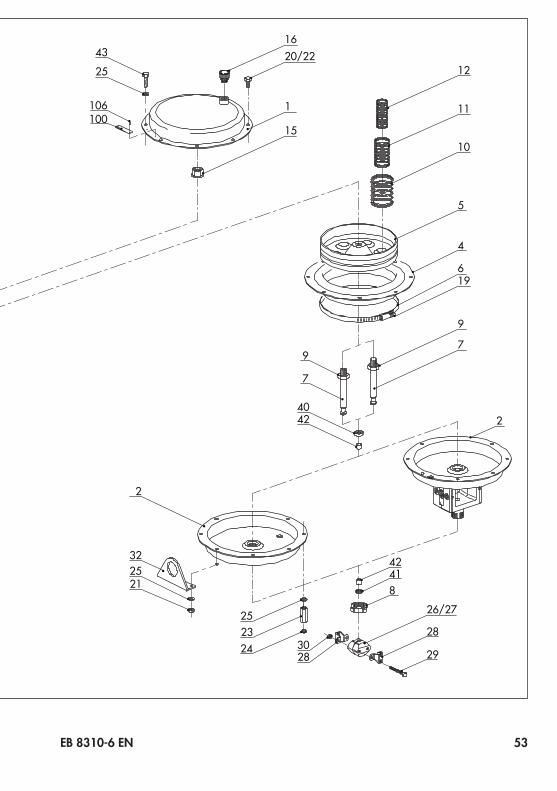
10.2 Spare parts1 Top diaphragm case2 Bottom diaphragm case4 Diaphragm5 Diaphragm plate6 Hose clamp7 Actuator stem8 Ring nut9 Hexagon nut
10 Spring11 Spring12 Spring15 Collar nut16 Vent plug19 Compressor on the hose clamp (6)20 Hexagon bolt21 Hexagon nut22 Hexagon bolt (preloading)23 Hexagon nut (preloading)24 Screw plug25 Washer
26/27 Stem connector clamp28 Clamp with bracket29 Hexagon bolt30 Hexagon nut32 Hanger40 Radial shaft seal41 Wiper42 Dry bearing43 Hexagon screw for hanger (32)49 Wiper 1)
50 Top actuator stem51 Stem connector52 Screwed flange54 Ring55 Pointer
56 Hexagon nut 1)
57 Coupling nut58 Washer59 Yoke60 Handwheel61 Dowel pin62 Dowel pin63 Threaded pin64 Cap screw65 Hexagon screw66 Lock nut67 Snap ring68 Axial needle seal69 Washer70 Adjustment nut73 Cover74 Lock nut75 Top diaphragm case76 Radial shaft seal77 Dry bearing
100 Nameplate101 Label (preloading)106 Grooved pin
1) Only for version with 240 cm² actuator area2) Replaces collar nut (15) in version with travel
stop or handwheel
52 EB 8310-6 EN
4240
7
9
196
4
5
10
11
12
79
2
2
322521
252324 30
28
26/27
28
29
42418
1620/22
15
43
25
106100
1
106100
51
50
56
50
68
5462
67
686957
58
638
59
41/4942
20/22
65
52
66
5564
60
61
52
7677
1620/2225
75
4241
106100
50
20/22
16707473
20/22
75
50
56
EB 8310-6 EN 53
4240
7
9
196
4
5
10
11
12
79
2
2
322521
252324 30
28
26/27
28
29
42418
1620/22
15
43
25
106100
1
106100
51
50
56
50
68
5462
67
686957
58
638
59
41/4942
20/22
65
52
66
5564
60
61
52
7677
1620/2225
75
4241
106100
50
20/22
16707473
20/22
75
50
56

54 EB 8310-6 EN

EB 8310-6 EN 55

2018
-05-
28 ·
Engl
ish
SAMSON AKTIENGESELLSCHAFTWeismüllerstraße 3 · 60314 Frankfurt am Main, GermanyPhone: +49 69 4009-0 · Fax: +49 69 [email protected] · www.samson.de
EB 8310-6 EN


![[XLS]advisor.morningstar.comadvisor.morningstar.com/Enterprise/VTC/DataDictionary... · Web view3269 3270 3271 3272 3273 3274 3275 3276 3277 3278 3279 3280 3281 3282 3283 3284 3285](https://static.fdocuments.net/doc/165x107/5b09e7837f8b9a99488b5c29/xls-view3269-3270-3271-3272-3273-3274-3275-3276-3277-3278-3279-3280-3281-3282.jpg)