Type 3241 PSA Globe Valve · DIN version · Control valves for PSA plants (Pressure Swing...
12
T 8015-1 EN SAMSON AKTIENGESELLSCHAFT · Weismüllerstraße 3 · 60314 Frankfurt am Main, Germany Phone: +49 69 4009-0 · Fax: +49 69 4009-1507 · [email protected] · www.samson.de Edition October 2016 Application Control valves for PSA plants (Pressure Swing Adsorption) Valve sizes DN 15 to 150 Pressure rating PN 10 to 40 Medium temperatures –10 to +220 °C Series 240 · Types 3241‑1 PSA, ‑7 PSA, ‑9 PSA Pneumatic Control Valves Type 3241 PSA Globe Valve · DIN version Fig. 1: Type 3241‑7 PSA, DN 15 to 80, forged steel Fig. 2: Type 3241‑1 PSA, DN 15 to 80 Fig. 3: Type 3241‑9 PSA, DN 15 to 150 Further versions – Flow divider · For cast valves for noise reduction in both directions of flow – ANSI version · See Data Sheet u T 8012-1 – Versions with dimensions according to Japanese Industry Standard (JIS) · Details on request Type 3241 Globe Valve operated with • Type 3271 Pneumatic Actuator (Type3241-1 Control Valve) • Type 3277 Pneumatic Actuator (Type 3241-7 Control Valve) for integral positioner attachment • Type 3275 Pneumatic Piston Actuator (Type 3241-9 Con- trol Valve) Valve body made of • Cast steel • Cast stainless steel or cast cold-resisting steel • Forged steel • Forged stainless steel Undivided valve bonnet Valve plug • Soft seal • High-performance metal seal The control valves, designed according to the modular assem- bly principle, can be equipped with various accessories: Positioners, solenoid valves and other accessories according to IEC 60534-6-1 1) and NAMUR recommendation. Refer to Information Sheet u T 8350 for more details. Versions Standard version for medium temperatures ranging from –10 to +220 °C – Type 3241‑1 PSA (Fig. 2) · DN 15 to 80 with Type 3271 Actuator (see Data Sheet u T 8310-1) – Type 3241‑7 PSA (Fig. 1) · DN 15 to 80 with Type 3277 Actuator (see Data Sheet u T 8310-1) – Type 3241‑9 PSA (Fig. 3) · DN 15 to 150, with Type 3275 Piston Actuator (u T 8314) for integral attach- ment of a positioner and/or limit switch 1) Accessories required. See associated actuator documentation.
Transcript of Type 3241 PSA Globe Valve · DIN version · Control valves for PSA plants (Pressure Swing...

T 8015-1 EN
SAMSON AKTIENGESELLSCHAFT · Weismüllerstraße 3 · 60314 Frankfurt am Main, Germany Phone: +49 69 4009-0 · Fax: +49 69 4009-1507 · [email protected] · www.samson.de
Edition October 2016
ApplicationControl valves for PSA plants (Pressure Swing Adsorption)Valve sizes DN 15 to 150Pressure rating PN 10 to 40Medium temperatures –10 to +220 °C
Series 240 · Types 3241‑1 PSA, ‑7 PSA, ‑9 PSA Pneumatic Control ValvesType 3241 PSA Globe Valve · DIN version
Fig. 1: Type 3241‑7 PSA, DN 15 to 80, forged steel
Fig. 2: Type 3241‑1 PSA, DN 15 to 80
Fig. 3: Type 3241‑9 PSA, DN 15 to 150
Further versions – Flow divider · For cast valves for noise reduction in both
directions of flow – ANSI version · See Data Sheet u T 8012-1 – Versions with dimensions according to Japanese Industry
Standard (JIS) · Details on request
Type 3241 Globe Valve operated with • Type 3271 Pneumatic Actuator (Type 3241-1 Control Valve) • Type 3277 Pneumatic Actuator (Type 3241-7 Control
Valve) for integral positioner attachment • Type 3275 Pneumatic Piston Actuator (Type 3241-9 Con-
trol Valve)Valve body made of
• Cast steel • Cast stainless steel or cast cold-resisting steel • Forged steel • Forged stainless steel
Undivided valve bonnetValve plug
• Soft seal • High-performance metal seal
The control valves, designed according to the modular assem-bly principle, can be equipped with various accessories:Positioners, solenoid valves and other accessories according to IEC 60534-6-1 1) and NAMUR recommendation. Refer to Information Sheet u T 8350 for more details.VersionsStandard version for medium temperatures ranging from –10 to +220 °C – Type 3241‑1 PSA (Fig. 2) · DN 15 to 80 with Type 3271
Actuator (see Data Sheet u T 8310-1) – Type 3241‑7 PSA (Fig. 1) · DN 15 to 80 with Type 3277
Actuator (see Data Sheet u T 8310-1) – Type 3241‑9 PSA (Fig. 3) · DN 15 to 150, with
Type 3275 Piston Actuator (u T 8314) for integral attach-ment of a positioner and/or limit switch
1) Accessories required. See associated actuator documentation.

2 T 8015-1 EN
Principle of operationThe process medium flows through the valve in both direc-tions. The valve plug position determines the cross-sectional area between the seat and plug.
Fail-safe positionDepending on how the springs are arranged in the Type 3271 or Type 3277 Actuator (u T 8310-1), the valve has two dif-ferent fail-safe positions effective upon air supply failure:Actuator stem extends (fail-close) The valve closes when the supply air fails.Actuator stem retracts (fail-open) The valve opens when the supply air fails.The double-acting Type 3275 Piston Actuator does not have a fail-safe action (see u T 8314).
Fig. 4: Type 3241 PSA Valve, DN 15 to 150, with flow divider St I PSA
Fig. 5: Type 3241‑9 PSA Control Valve, DN 15 to 150, with Type 3275 Pneumatic Piston Actuator
Fig. 6: Type 3241‑1 PSA Valve in forged steel, DN 15 to 80

T 8015-1 EN 3
Table 1: Technical data for Type 3241 PSA Valve
Valve size DN 15 to 150 15, 25, 40, 50, 80
Material Cast steelGP240GH
1.0619
Cast stainless steel1.4408
Forged steelP250GH1.0460
Forged stainless steel1.4571
Type of end connections Flange (all DIN versions)
Pressure rating PN 10, 16, 25, 40
Seat/plug seal Soft seal or high-performance metal seal
Characteristic Equal percentage or linear
Rangeability 50:1 for DN 15 to 50 · 30:1 for DN 65 and larger
Compliance ·
Medium temperature ranges in °C · Permissible operating pressures acc. to pressure-temperature diagram (see Information Sheet u T 8000-2)
Valve –10 to +220 °C
Leakage class according to IEC 60534-4
Valve plug Soft seal VI
High-performance metal seal V
Table 2: Materials
Standard version
Pressure rating PN 16 to 40
Valve body 1)Cast steelGP240GH
1.0619
Cast stainless steel1.4408
Forged steelP250GH1.0460
Forged stainless steel1.4571
Valve bonnet 1.0460 1.4404/1.4401 2) 1.0460 1.4571
Seat and plug1.4006 1.4004 1.4406 1.4404
Seal ring for soft-seated plug: PTFE with glass fiber
Guide bushings 1.4104 1.4404 1.4104 1.4404
Packing V-ring packing: PTFE with carbon · Spring: 1.4310 · Stem protective ring
Body gasket Graphite on metal core
1) Special materials on request2) Double stamping of the material

4 T 8015-1 EN
Table 3: KVS coefficientsTerms for control valve sizing according to IEC 60534, Parts 2-1 and 2-2: FL = 0.95, XT = 0.75
Table 3.1: Overview with flow divider St I PSA (KVS I)
KVS 1.6 2.5 4.0 6.3 10 16 25 40 60 80 63 100 160 200 260
KVS I 1.3 2 3.2 5 8 13 20 32 48 63 50 80 125 160 210
Seat Ø mm 12 24 31 38 48 63 80 63 80 100 110 130
Travel mm 15 30
Table 3.2: Versions without flow divider
KVS 1.6 2.5 4.0 6.3 10 16 25 40 60 80 63 100 160 200 260
Valve size DN
15 • • •
20 • • •
25 • • •
32 • • •
40 • • •
50 • • •
65 • • •
80 • • •
100 • • •
125 • • •
150 • • •
Table 3.3: Versions with flow divider St I PSA (KVS I) · Versions with cast bodies only
KVS I 1.3 2 3.2 5 8 13 20 32 48 63 50 80 125 160 210
Valve size DN
15 • • •
20 • • •
25 • • •
32 • • •
40 • • •
50 • • •
65 • • •
80 • • •
100 • • •
125 • •
150 • • •
Notes on the differential pressure tablesThe differential pressure tables have been prepared under the following conditions: – The maximum permissible supply pressure is 4 bar for valves in sizes DN 15 to 50 and actuators with an effective diaphragm
area of 700 cm² – Process medium in flow-to-open direction – Version with PTFE packing – The leakage rates specified in Table 1 are not exceeded with the maximum differential pressures specified. – The specified differential pressure may be restricted by the pressure-temperature diagram.sure-temperature diagrams).
T 8015-1 EN 5
Table 4: Differential pressure tables for Type 3271 and Type 3277 Actuators with Type 3241 PSA Valve · All pressures in bar – Permissible differential pressures Δp for unbalanced plug with high-performance metal seal when p2 = 0 – Values specified in the gray-shaded columns correspond to the standard application cases, i.e. operation with rated travel – Differential pressures specified in the white columns apply to maximum pretensioned springs – Values in parentheses are valid for 50 % travel.
Table 4.1: Fail‑close valve · Valve closed with 0 bar signal pressure
Bench range with actuator
240 cm²
0.2 to 1.0
0.3 to 1.1
0.4 to 2.0
0.6 to 2.2
0.6 to 3.0
0.9 to 3.3 – –120 cm²350 cm²700 cm² 0.4 to 1.2 0.8 to 2.4 1.2 to 3.6
1.4 to 2.3 2.1 to 3.3
700 cm² (1.2 to 2.0) (1.8 to 3.0) (1.85 to 2.3) (2.7 to 3.3)Required supply pressure 1.2 1.4 2.2 2.6 3.2 3.8 2.5 3.5Valve size
DN KVSActuator
cm² Δp when p2 = 0 bar
15 to 251.62.54.0
120 – – 28 – – – 40 –240 28 40 40 40 40 40 – –350 40 40 40 40 – – 40 –
20 to 40 6.310.0
120 – – – – – – 30 40240 – – 14.8 24 24 39 – –350 – – 24 38 38 40 40 40700 – – (40) – – – – –
32 to 50 16240 – – – 14 14 23 – –350 – 13.5 30 22 47 40 40700 – – (40) – (40) – – –
40 to 65 25350 – – – 20 14 31 37 40700 – – (40) – (40) – – –
50 to 80 40350 – – – 12 8.5 19 23 35700 – – (40) – (40) – – –
6580 60
350 – – – – 4.5 10.5 13 20700 – – (23) – (35) – (36) (40)
80 80 700 – – (14) – (21) – (22) (33)
Table 4.2: Fail‑open valve · Valve closed with the required signal pressure
Bench range with actuator
240 cm²
0.2 to 1.0120 cm²350 cm²700 cm²
Required supply pressure 1.2 2.4 4.0Valve size
DN KVSActuator
cm² Δp when p2 = 0 bar
15 to 251.62.54.0
120 9 40 –240 28 40 –350 40 40 –
20 to 40 6.310.0
120 – 31 40240 – – –350 – 40 40700 24 40 –
32 to 50 16240 – 27 40350 5.2 40 40700 13.5 40 –
40 to 65 25350 – 37 40700 – 40 40
50 to 80 40350 – 23 40700 – 40 40
6580 60
350 – 13 29700 – 27 40
80 80 700 – 16 37
6 T 8015-1 EN
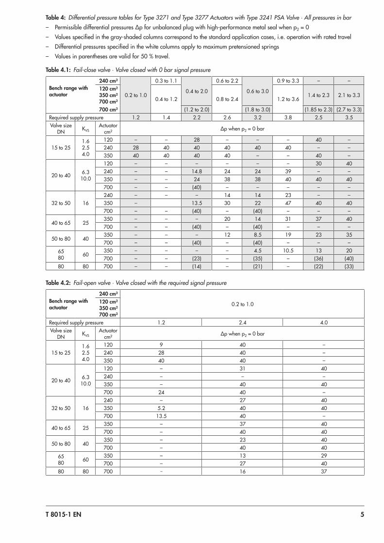
Table 5: Permissible differential pressure for Type 3275 Piston Actuator with Type 3241 PSA ValveTable 5.1: Plug with high‑performance metal seal · Pressures in bar
Valve size DN
Flow coefficient
KVS
Actuator cm²
Supply pressure [bar]
1.4 2 2.5 3 3.5 4 5 6
20 to 40 6.3 to 10 314 40 – – – – – – –
32 to 50 16314 26.5 40 – – – – – –
490 40 – – – – – – –
40 to 65 25314 14.4 28.2 39.8 – – – – –
490 32.5 40 – – – – – –
50 to 65 40314 6.1 14.8 22.0 29.3 35.5 40 – –
490 17.5 31.0 40 – – – – –
65 60314 1.0 6.1 10.3 14.5 18.7 22.9 31.3 39.6
490 7.6 15.5 22.0 28.6 35.1 40 – –
80 40314 6.0 14.7 21.9 29.1 36.4 40 – –
490 17.3 30.9 40 – – – – –
80 60314 1.0 6.0 10.2 14.4 18.6 22.8 31.2 39.6
490 7.5 15.4 22.0 28.5 35.1 40 – –
80 80314 – 1.9 4.5 7.2 9.8 12.4 17.6 22.8
490 2.9 7.8 11.8 15.9 20.0 24.0 32.2 40
100 63
314 1.0 6.0 10.2 14.4 18.6 22.8 31.2 39.6
490 7.5 15.4 22.0 28.5 35.1 40 – –
804 19.3 32.2 40 – – – – –
100125 100
314 – 1.9 4.5 7.2 9.8 12.4 17.6 22.8
490 2.9 7.8 11.8 15.9 20.0 24.0 32.2 40
804 10.2 18.2 24.9 31.5 38.2 40 – –
100 to 150 160
314 – – 1.6 3.2 4.9 6.6 9.9 13.2
490 0.5 3.6 6.2 8.8 11.4 14.0 19.2 24.4
804 5.2 10.3 14.6 18.8 23.1 27.4 35.9 40
125 200
314 – – 0.8 2.1 3.5 4.9 7.6 10.4
490 – – 4.6 6.8 8.9 11.1 15.4 19.6
804 3.7 8.0 11.5 15.0 18.5 22.1 29.1 36.2
150 260
314 – – – 0.7 1.7 2.7 4.7 6.6
490 – 1.0 2.5 4.1 5.6 7.1 10.2 13.3
804 1.9 4.9 7.4 10.0 12.5 15.0 20.1 25.1

T 8015-1 EN 7
Table 5.2: Soft‑seated plug · Pressures in bar
Valve size DN
Flow coefficient
KVS
Actuator cm²
Supply pressure [bar]
1.4 2 2.5 3 3.5 4 5 6
20 to 40 6.3 to 10 314 40 – – – – – – –
32 to 50 16 314 40 – – – – – – –
40 to 65 25 314 31.8 40 – – – – – –
50 to 65 35314 19.9 28.6 35.8 40 – – – –
490 31.2 40 – – – – – –
65 60314 11.4 16.5 20.7 24.9 29.1 33.3 40 –
490 18.0 25.9 32.4 39.0 40 – – –
80 40314 19.7 28.4 35.6 40 – – – –
490 31.1 40 – – – – – –
80 60314 11.1 16.5 20.7 24.9 29.1 33.3 40 –
490 18.0 25.9 32.4 39.0 40 – – –
80 80314 7.1 10.2 12.8 15.4 18.0 20.6 25.8 31.0
490 11.2 16.0 20.1 24.2 28.2 32.3 40 –
100 63
314 11.4 16.5 20.7 24.9 29.1 33.3 40 –
490 18.0 25.9 32.4 39.0 40 – – –
804 29.8 40 – – – – – –
100125 100
314 7.1 10.2 12.8 15.4 18.0 20.6 25.8 31.0
490 11.2 16.0 20.1 24.2 28.2 32.3 40 –
804 18.4 26.4 33.1 39.8 40 – – –
100 to 150 160
314 4.5 6.5 8.2 9.8 11.5 13.2 16.5 19.8
490 7.1 10.2 12.8 15.4 18.0 20.6 25.8 31.0
804 11.8 16.9 21.2 25.4 29.7 34.0 40 –
125 200
314 3.7 5.4 6.8 8.1 9.5 10.9 13.6 16.4
490 5.9 8.5 10.6 12.8 14.9 17.1 21.4 25.6
804 9.7 14.0 17.5 21.0 24.5 28.1 35.1 40
150 260
314 2.7 3.8 4.8 5.8 6.8 7.8 9.8 11.7
490 4.2 6.1 7.6 9.1 10.7 12.2 15.3 18.4
804 7.0 10.0 12.5 15.0 17.6 20.1 25.1 30.2

8 T 8015-1 EN
Table 6: Dimensions for Type 3241‑1 PSA, Type 3241‑7 PSA and Type 3241‑9 PSA in standard version
Table 6.1: Type 3241 PSA Valve
Valve DN 15 20 25 32 40 50 65 80 100 125 150
Length L mm 130 150 160 180 200 230 290 310 350 400 480
H1 for actuator mm 220 330 1) 330 1) 354 1) 363 1) 390 1)
H2 for versionCast steel mm 40 72 98 118 144 175
Forged steel mm 53 – 70 – 92 98 – 128 –
1) Add 65 mm to H1 when a Type 3275 Actuator with 804 cm² actuator area is mounted.
Table 6.2: Type 3271 and Type 3277 Pneumatic Actuators
Actuator area cm² 120 350 700
Diaphragm ØD mm 168 280 390
H 1) mm 69 82 199
H3 2) mm 110 110 190
H5 Type 3277 mm 88 101 101
ThreadType 3271 M30 x 1.5
Type 3277 M30 x 1.5
a Type 3271 G 1/8 (1/8 NPT) G 3/8 (3/8 NPT) G 3/8 (3/8 NPT)
a2 Type 3277 – G 3/8 G 3/8
1) Height with welded-on lifting eyelet or height of eyebolt according to DIN 580. Height of the swivel lifting hook may differ. Actuators up to 350 cm² without lifting eyelet
2) Minimum clearance required to remove the actuator
Table 6.3: Type 3275 Piston Actuator
Actuator area cm² 314 490 804
Diaphragm D mm 220 280 350
H mm 225 1) 250 1) 286
H3 2) mm 110 190
H5 mm 101 –
Thread M30x1.5 M60x1.5
1) Different dimensions are possible for special version (e.g. for low temperatures).2) Minimum clearance to remove the actuator
Table 7: Weights for Type 3241‑1 PSA, Type 3241‑7 PSA and Type 3241‑9 PSA
Table 7.1: Type 3241 PSA Valve
Valve DN 15 20 25 32 40 50 65 80 100 125 150
Weight without actuator kg 5 6 7 11 12 15 24 30 42 80 120
Table 7.2: Type 3271, Type 3277, and Type 3725 Actuators
Actuator Type 3271 Type 3277 Type 3275
Actuator area cm² 120 350 700 120 350 700 314 490 804
Weight, approx. kg 3 8 22 3.5 12 26 10 17 21

T 8015-1 EN 9
Dimensional drawings
ØDH3
H2
H1
a
L
H H5
a2
H
H1
H2
H3
L
ØDa
H3
H
H1
H2
L
D
H5
H3
H
H1
H2
L
D
Type 3271 Actuator
Type 3241-1 PSA DN 15 to 80
Type 3241-7 PSA DN 15 to 80
Type 3241-9 PSA DN 15 to 150
Type 3241-9 PSA DN 100 to 150
Type 3277 Actuator
Type 3275 Piston Actuator
314/490 cm² Type 3275 Piston Actuator, 804 cm²

10 T 8015-1 EN
Ordering text
Globe valve Type 3241 PSAValve size DN …Pressure rating PN …Body material According to Table 2Type of end connections
Flanges
Seat/plug seal Soft seal or high-performance metal seal
Characteristic Equal percentage or linearActuator Type 3271, Type 3277 or Type 3275
according to Data Sheet u T 8310-1 or u T 8314
Fail-safe position Fail-close or fail-openProcess medium Density in kg/m³ and temperature in °CFlow rate in kg/h or m³/h in standard or operat-
ing statePressure p1 and p2 in bar (absolute pressure
pabs), with minimum, normal and maxi-mum flow rate
Valve accessories Positioner and/or limit switch
Associated Data Sheets for pneumatic actuators:Type 3271 and Type 3277 u T 8310‑1Type 3275 u T 8314Associated Mounting and Operating Instructions u EB 8015

T 8015-1 EN 11

Specifications subject to change without notice T 8015-1 EN 2019
-08-
05 ·
Engl
ish