Type 3004 data sheet | Explosion Proof Rotary Actuator ...
12
Visit product website DATA SHEET Type 2651 2/2 or 3/2 way Ball Valve, 2-Piece Type 2654 2/2 way ball valve 3-piece Type 2657 Ball Valve, manual- ly-operated Type 2671 Butterfly valve Type 2674 Plastic butterfly valve 1000097022 | Standard | EU | en | 202108 | 19 Explosion Proof Rotary Actuator - On/Off and control • Direct mounting for quarter-turn valves • Manual override • Corrosion resistant • Adjustable limit switches • ATEX II 2 GD Ex d II B T6 The rotary actuator type 3004 is a compact, powerful and explosion proofed actuator system which provides a long service life. Materials and components have been chosen for maintenance-free operation and ensure low thermal loading on the actuator. The modular design offers many options such as extra limit switches or potentiometers, to be added to the basic unit. Product variants described in the data sheet may differ from the product presentation and description. Type description Can be combined with Type 3004 © Christian Bürkert GmbH & Co. KG, Subject to alteration
Transcript of Type 3004 data sheet | Explosion Proof Rotary Actuator ...

Visit product website
DATA SHEET
Type 2651
2/2 or 3/2 way Ball Valve, 2-Piece
Type 2654
2/2 way ball valve 3-piece
Type 2657
Ball Valve, manual-ly-operated
Type 2671
Butterfly valve
Type 2674
Plastic butterfly valve
1000097022 | Standard | EU | en | 202108 | 19
Explosion Proof Rotary Actuator - On/Off and control
• Direct mounting for quarter-turn valves
• Manual override
• Corrosion resistant
• Adjustable limit switches
• ATEX II 2 GD Ex d II B T6
The rotary actuator type 3004 is a compact, powerful and explosion proofed actuator system which provides a long service life. Materials and components have been chosen for maintenance-free operation and ensure low thermal loading on the actuator. The modular design offers many options such as extra limit switches or potentiometers, to be added to the basic unit.
Product variants described in the data sheet may differ from the product presentation and description.
Type descriptionCan be combined with
Type 3004
© Christian Bürkert GmbH & Co. KG, Subject to alteration

Type 3004
2 | 12Visit product website
Table of contents
1. General Technical Data 3
2. Materials 4
2.1. Chemical Resistance Chart – Bürkert resistApp....................................................................................................................4
3. Dimensions 4
3.1. Motor 25, 45, 75 Nm ...............................................................................................................................................................43.2. Motor 100, 150, 300 Nm .........................................................................................................................................................5
4. Device/Process connections 6
4.1. Multi-voltage or 24 V AC/DC standard version ......................................................................................................................64.2. Multi-voltage or 24 V AC/DC with programmable analogue signal input or output ..............................................................7
5. Product design and assembly 8
5.1. Product features ....................................................................................................................................................................8
6. Ordering information 9
6.1. Bürkert eShop – Easy ordering and quick delivery ................................................................................................................96.2. Bürkert product filter ..............................................................................................................................................................96.3. Ordering chart ........................................................................................................................................................................9
Standard version without analogue signal input ....................................................................................................................9Control version with 4…20 mA, 0…20 mA or 0…10 V programmable analogue signal input or output .............................10
6.4. Ordering chart accessories ..................................................................................................................................................10Conversion sleeves ..............................................................................................................................................................10Replacement battery for actuators with electrical emergency reset function .....................................................................11

Type 3004
3 | 12Visit product website
1. General Technical Data
Product propertiesDimensions Detailed information can be found in chapter “3. Dimensions” on page 4.
MaterialCover / Body Epoxy coated aluminiumAxis / Screw Stainless steelGear Stainless steel
ISO MountingMotor 25, 45, 75 Nm F05/F07Motor 100, 150, 300 Nm F07/F10
DriveMotor 25 Nm Female star 17 mm; conversion sleeve star 17/11 mm enclosedMotor 45, 75 Nm Female star 17 mm; conversion sleeve star 17/14 mm enclosedMotor 100, 150, 300 Nm Female star 22 mm; conversion sleeve star 22/17 mm enclosed
Manual overrideMotor 25, 45, 75 Nm By outgoing axis with return springMotor 100, 150, 300 Nm By hand wheel
WeightMotor 25, 45, 75 Nm 4 kgMotor 100, 150, 300 Nm 6 kgMechanical limit stops StandardOptical position indicator StandardPerformance dataTorque 25, 45, 75, 100, 150 und 300 Nm
Detailed information can be found in chapter “6. Ordering information” on page 9.Position angle 90° (± 5°)Actuating time (10…90 %) 7…50 sec.
Detailed information can be found in chapter “6. Ordering information” on page 9.Options Rotation 180° or 270°
3 position actuator (for 180°) Feedback On/Off actuators: - Potentiometer 1K, 5K, or 10K - Analogue signal 4…20 mA Fail safe option* (on request) 2 extra limit switches
Electrical dataOperating voltage 100…240 V AC / 50…60 Hz oder 24 V AC/DC ± 10 %Limit switches 4 adjustable (2 for motor and 2 additional for feedback) max. 250 V AC/5 APower consumption 45 W…85 WVoltage tolerance ± 10 %
Analogue signals control versionInput - 0…10 V / - 4…20 mA / - 0…20 mAOutput - 0…10 V / - 4…20 mA / - 0…20 mAMotor protection Electronic torque limitedDuty cycle At max. torque: 50 % of the time
Control actuator: 50 % of max. torqueHeating resistor 10 WProcess/Port connection & communicationElectrical connection 2 cable glands ISO 20Environment and installationInstallation position Do not mount the actuator upside down!Ambient temperature - 20 °C…+ 70 °CDegree of protection IP68

Type 3004
4 | 12Visit product website
2. Materials2.1. Chemical Resistance Chart – Bürkert resistApp
Bürkert resistApp – Chemical Resistance Chart
You want to ensure the reliability and durability of the materials in your individual application case? Verify your combination of media and materials on our website or in our resistApp.
Start Chemical Resistance Check
3. Dimensions3.1. Motor 25, 45, 75 Nm
Note:Dimensions in mm
ø 170 198
95
201
20 ø 70 ISO F074xM8
ø 50 ISO F054xM6

Type 3004
5 | 12Visit product website
3.2. Motor 100, 150, 300 Nm
Note:Dimensions in mm
ø 102 ISO F104xM10
ø 70 ISO F074xM8
20
18035
95
57
35
259
275
ø 170
Type 3004
6 | 12Visit product website
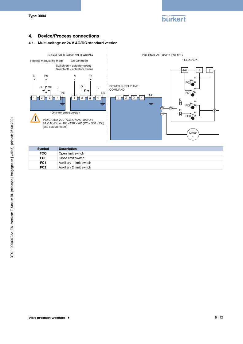
4. Device/Process connections4.1. Multi-voltage or 24 V AC/DC standard version
N-
Ph+
N-
Ph+
FC2
FC1
FCF
FC0
4-6 5 7
=
C C
A B
D
D
T/E 1 2 3 4 1 2 3 4
T/E T/E
1 2 3 4
* *
3-points modulating mode On-Off mode
Switch on = actuator opensSwitch off = actuators closes
POWER SUPPLY ANDCOMMAND
FEEDBACK
On OnOff
Motor
INDICATED VOLTAGE ON ACTUATOR:24 V AC/DC or 100 - 240 V AC (120 - 350 V DC) (see actuator label)
SUGGESTED CUSTOMER WIRING INTERNAL ACTUATOR WIRING
* Only for probe version
Symbol DescriptionFCO Open limit switchFCF Close limit switchFC1 Auxiliary 1 limit switchFC2 Auxiliary 2 limit switch

Type 3004
7 | 12Visit product website
4.2. Multi-voltage or 24 V AC/DC with programmable analogue signal input or output
T/E
FC2
FC1
FCF
FC0
4-6 5 7
=
C B
D
D A
C
17 18
18 17
N -
Ph +
N -
Ph +
16
15
14
13
+
-
-
+
0-20
mA
/ 4
-20
mA
/ 0
-10
V
1 2 3 4
*
POWER SUPPLY:100 - 240 V AC (120 - 350 V DC)
Actu
ator
pow
er s
uppl
y(s
ee a
ctua
tor l
abel
)
POWER SUPPLY:24 V AC/DC
Onl
y fo
r 10
0 -
240
V A
C (1
20 -
350
V D
C)
INPUT
FEEDBACK
AUXILIARY FEEDBACK
Motor
* Only for probe version
Symbol DescriptionFCO Open limit switchFCF Close limit switchFC1 Auxiliary 1 limit switchFC2 Auxiliary 2 limit switch

Type 3004
8 | 12Visit product website
5. Product design and assembly5.1. Product features
Motor 25, 45, 75 Nm Motor 100, 150, 300 Nm
1
2
3
4
7
8
9.a
10
11
12
13
14
16
6
5
17
15
1
2
3
4
7
8
9.b
10
11
12
13
14
16
6
5
18
17
15
No. Element1 Optical position indicator2 Cover3 Stainless steel screws4 Motor5 Power supply card6 Gear box7 O-ring8 Gear
9.a Manual override9.b Hand wheel10 Housing11 Identification label12 Auxiliary limit switch terminal13 Cams14 Power supply terminal15 Internal thread M20 × 1.516 Earth screw17 Positioning card (only actuator with position control)18 Mechanical limit stops

Type 3004
9 | 12Visit product website
6. Ordering information6.1. Bürkert eShop – Easy ordering and quick delivery
Bürkert eShop – Easy ordering and fast delivery
You want to find your desired Bürkert product or spare part quickly and order directly? Our online shop is available for you 24/7. Sign up and enjoy all the benefits.
Order online now
6.2. Bürkert product filter
Bürkert product filter – Get quickly to the right product
You want to select products comfortably based on your technical requirements?Use the Bürkert product filter and find suitable articles for your application quickly and easily.
Try out our product filter
6.3. Ordering chart
Standard version without analogue signal input
Note:• For the actuator choice, we recommend a safety torque equal to 1.5 times of the valve maximal torque (2 times for the control
version).
• Other regulating times and delay angles on request
Drive stars Conversion adapter star
Connection flange
Torque 90° ravel
Powerconsump-tion
Voltage /Frequency
Article no.
[mm] [mm] [Nm] [s] [W] [V / Hz]17 17/11 F05-F07 25 7 45 100…240 V AC, / 50/60 Hz / 100…350 V DC 181308
15…30 V AC, 50/60 Hz / 12…48 V DC1.) 181309 17/14 F05-F07 45 15 45 100…240 V AC, / 50/60 Hz / 100…350 V DC 181310
15…30 V AC, 50/60 Hz / 12…48 V DC1.) 181311 75 20 45 100…240 V AC, / 50/60 Hz / 100…350 V DC 181312
15…30 V AC, 50/60 Hz / 12…48 V DC1.) 181313 22 22/17 F07-F10 100 15 45 100…240 V AC, / 50/60 Hz / 100…350 V DC 181314
15…30 V AC, 50/60 Hz / 12…48 V DC1.) 181315 150 30 45 100…240 V AC, / 50/60 Hz / 100…350 V DC 181316
15…30 V AC, 50/60 Hz / 12…48 V DC1.) 181317 300 60 45 100…240 V AC, / 50/60 Hz / 100…350 V DC 181318
15…30 V AC, 50/60 Hz / 12…48 V DC1.) 181319
1.) The operating voltage mustn’t to fall below 11.5 V

Type 3004
10 | 12Visit product website
Control version with 4…20 mA, 0…20 mA or 0…10 V programmable analogue signal input or output
Note:• For the actuator choice, we recommend a safety torque equal to 1.5 times of the valve maximal torque (2 times for the control
version).
• Other regulating times and delay angles on request
Drive stars Conversion adapter star
Connection flange
Torque 90° ravel
Powerconsump-tion
Voltage /Frequency
Article no.
[mm] [mm] [Nm] [s] [W] [V / Hz]17 17/11 F05-F07 25 15 45 100…240 V AC, / 50/60 Hz / 100…350 V DC 182324
15…30 V AC, 50/60 Hz / 12…48 V DC1.) 182326 17/14 F05-F07 45 15 45 100…240 V AC, / 50/60 Hz / 100…350 V DC 182327
15…30 V AC, 50/60 Hz / 12…48 V DC1.) 182330 75 20 45 100…240 V AC, / 50/60 Hz / 100…350 V DC 182335
15…30 V AC, 50/60 Hz / 12…48 V DC1.) 182384 22 22/17 F07-F10 100 15 45 100…240 V AC, / 50/60 Hz / 100…350 V DC 182385
15…30 V AC, 50/60 Hz / 12…48 V DC1.) 182386 150 30 45 100…240 V AC, / 50/60 Hz / 100…350 V DC 182388
15…30 V AC, 50/60 Hz / 12…48 V DC1.) 182390 300 60 45 100…240 V AC, / 50/60 Hz / 100…350 V DC 182392
15…30 V AC, 50/60 Hz / 12…48 V DC1.) 182394
1.) The operating voltage mustn’t to fall below 11.5 V
Further versions on request
VoltageOther voltages
6.4. Ordering chart accessories
Conversion sleeves
Description Article no.Conversion Sleeve star/square14/9 mm 665288 Conversion Sleeve star/square 14/11 mm 665289 Conversion Sleeve square/square 17/14 mm 665290 Conversion Sleeve star/square 17/14 mm 773348 Conversion Sleeve star/square 17/11 mm 773343 Conversion Sleeve square/square 22/19 mm 773836 Conversion Sleeve star/square 22/17 mm 684858 Conversion Sleeve star/star 22/14 mm 666684 Conversion Sleeve star/square 22/11 mm 773344 Conversion Sleeve star/square 27/22 mm 774594 Conversion Sleeve square/square 27/19 mm 774279 Conversion Sleeve square/square 27/17 mm 774193

Type 3004
11 | 12Visit product website
Replacement battery for actuators with electrical emergency reset function
Note:• The battery has to be replaced every 2 years at the latest or after 500 charging cycles.
• Additional Info for Type 3004: The person who changes the battery must be trained and qualified to do modifications on ATEX products.
• Actuators which do not have an electronic emergency reset when delivered cannot be retrofitted with this.
Description Article no.Replacement battery for actuators of Type 3005 and 3004 (25Nm…300Nm) with electrical emergency reset function 772992

Bürkert – Close to You
AustriaBelgiumCzech Republic DenmarkFinlandFranceGermanyItalyNetherlands
NorwayPoland SpainSwedenSwitzerlandTurkeyUnited Kingdom
ChinaHong KongIndiaJapan KoreaMalaysiaPhilippinesSingaporeTaiwan
South Africa
Russia
United ArabEmirates
BrazilUruguay
CanadaUSA
AustraliaNew Zealand
Credits, © and concept: Christian Bürkert GmbH & Co. KG | Photographs: Marc Eggimann Fotografie - 4051 Basel | Scanner GmbH - Werbeagentur Künzelsau -
74653 Künzelsau
For up-to-date addresses please visit us atwww.burkert.com