Type 2E Module & BMT Software for Windowstm Display ...
41
BrainMaster tm System Type 2E Module & BMT Software for Windows tm Display Screens for Master.exe 1995 - 2004 BrainMaster Technologies, Inc., All Rights Reserved “BrainMaster” and “From the Decade of the Brain” are registered trademarks of BrainMaster Technologies, Inc. “Windows” is a trademark of Microsoft Corp. U.S. Patent Number 5,899,867 1. INTRODUCTION 3 1.1 UPDATE NOTICE 3 Part Number 531-003 Version 2.0SE 5/30/04 D-1
Transcript of Type 2E Module & BMT Software for Windowstm Display ...
BrainMastertm System Type 2E Module & BMT Software for Windows
tm
Display Screens for Master.exe
1995 - 2004 BrainMaster Technologies, Inc., All Rights Reserved
“BrainMaster” and “From the Decade of the Brain” are registered trademarks of BrainMaster Technologies, Inc.
“Windows” is a trademark of Microsoft Corp. U.S. Patent Number 5,899,867
1. INTRODUCTION 3
1.1 UPDATE NOTICE 3 Part Number 531-003 Version 2.0SE 5/30/04 D-1

1.2 USING THE DISPLAY 3 1.3 TWO SETS OF WINDOWS 3 1.4 TYPICAL TRAINING SCREEN DISPLAY 4
2. USING MENUS 5
2.1 DATA MENU 5 2.2 DISPLAY MENU 5 2.3 FREQUENCY BANDS MENU 6 2.4 COLOR MENU 6 2.5 SOUND MENU 7
3. DISPLAY PANES 9
3.1 REPORT PANE 9 3.2 COMMAND PANE 9 3.3 EEG WAVEFORM PANE 9 3.4 FILTERED WAVEFORMS PANE 10 3.5 PHASE SPACE PANE 11 3.6 FREQUENCY SPECTRUM (FFT) PANE 11 3.7 THERMOMETER PANE 13 3.8 BRAINMIRROR (FFT) PANE 14 3.9 BRAINMIRROR (FILTER) PANE 15 3.10 COHERENCE/PHASE PANE 16
4. ACCESSORY WINDOWS ERROR! BOOKMARK NOT DEFINED.
4.1 XWING WINDOW ERROR! BOOKMARK NOT DEFINED. 4.2 BRAINMAN WINDOW ERROR! BOOKMARK NOT DEFINED. 4.3 NUMBERS WINDOW ERROR! BOOKMARK NOT DEFINED. 4.4 THERMOMETER WINDOW ERROR! BOOKMARK NOT DEFINED. 4.5 WAVES WINDOW ERROR! BOOKMARK NOT DEFINED. 4.6 BOXFLOW WINDOW ERROR! BOOKMARK NOT DEFINED. 4.7 BRAINMIRROR WINDOW ERROR! BOOKMARK NOT DEFINED. 4.8 SPECTRAL WINDOW ERROR! BOOKMARK NOT DEFINED. 4.9 TRENDVIEW WINDOW ERROR! BOOKMARK NOT DEFINED. 4.10 CIRCLES WINDOW ERROR! BOOKMARK NOT DEFINED. 4.11 DOLPHIN ANIMATION: ERROR! BOOKMARK NOT DEFINED. 4.12 OPTIONAL ANIMATIONS: ERROR! BOOKMARK NOT DEFINED. 4.13 CONTRIBUTED GAME SCREENS: ERROR! BOOKMARK NOT DEFINED. 4.14 EXTRA SOFTWARE: ERROR! BOOKMARK NOT DEFINED. 4.15 EEG AUDIO CONTROL PANEL ERROR! BOOKMARK NOT DEFINED.
Part Number 531-003 Version 2.0SE 5/30/04 D-2

1. Introduction
1.1 Update Notice
This software is in the continual process of being updated. The screen displays that are shown are from the latest available version of the BrainMaster program, but as the software is updated, they may not look exactly the same as you will see in the current distribution. Nonetheless, the basic appearance and operation of the screens will be the same.
1.2 Using the display The BrainMaster screen is normally divided vertically into two sides, denoted "left" and "right." These two areas usually reflect the EEG activity from the respective sides of the head. The work area consists of "tiled" regions that provide the various types of displays.
1.3 Two sets of windows
There are two sets of displays in the BrainMaster. The first set comprise the “panes” that are selectable within the training screen. These automatically “tile” to fill the screen. Panes are turned on and off using the menu items at the top of the Training Screen, under the “Display” menu item. When a pane is selected (visible), its corresponding menu item will have a checkmark visible beside it. Any number of panes can be used. However, as more panes are used, they will need to occupy space at the bottom of the training screen. If your computer display does not have sufficient room (or pixels) to display them, they will not be visible. The second set is comprised of the “windows” that pop up when the corresponding pushbutton in the “Windows” dialog is pressed. These windows are standard Microsoft Windows windows, and have all the associated Windows properties. They can be resized, moved, minimized, and selected using the mouse. Each such window will also have an associated pushbutton appear on the “task bar” which is usually visible on the bottom of your Windows display. In many of the windows, text displays provide additional information. When appropriate, letters are used to identify EEG components. These are as follows: “d” for Delta, “t” for Theta, “a” for Alpha, “l” for LoBeta, “b” for Beta, “h” for High Beta, “g” for Gamma, and “u” for User. These are also the keyboard keys that can be used to adjust thresholds. Typing a lower-case letter will raise the corresponding threshold, and typing the upper-case letter will lower it.
Part Number 531-003 Version 2.0SE 5/30/04 D-3

1.4 Typical Training Screen Display
The following is a typical Training Screen display. It contains raw and filtered waveforms, the thermometer pane, and the FFT BrainMirror pane. In addition, the timer clock and points display are visible.
Part Number 531-003 Version 2.0SE 5/30/04 D-4

2. Using Menus It is intended that all on-screen displays have corresponding menu items. These menu items can be accessed using the mouse, in the conventional Windows manner, or can be accessed using the keyboard, by pressing the <Alt> key along with the key letter. The key letters are identified by their being underlined in the menu listing. Selected menu items have a checkmark to indicate that they are currently “active.” 2.1 Data Menu
This menu allows you to select the data source. The choices are a COM port (COM1, 2, 3, or 4), or a file for playback.
If you select Playback File, you will see a dialog box that shows the available files. Select the desired file and click on “OK” to begin the playback.
2.2 Display Menu
Part Number 531-003 Version 2.0SE 5/30/04 D-5

This menu allows you to select which panes are visible.
2.3 Frequency Bands Menu
This menu allows you to select which frequency bands (“components”) are visible.
2.4 Color Menu
This menu allows you to make some changes to the colors used in the training screen.
Part Number 531-003 Version 2.0SE 5/30/04 D-6

2.5 Sound Menu
This menu allows you to change the reward sounds, and also to access the MIDI sounds.
This menu allows you choose any of the 6 sound modes, and also to change the sound settings. It is also possible to turn sound feedback off entirely, using the “SOUND OFF” selection.
Part Number 531-003 Version 2.0SE 5/30/04 D-7

The MIDI Voice menu accesses the following dialog box. It contains a “combo box” selection list that will show the currently selected MIDI voice. The list has a selector button on the right of the name of the current voice.
When you click on the selector button on the right side of the list, the selector list will pop down as shown:
This list contains the 128 MIDI voices that you can choose from. Use your mouse or the cursor keys to navigate this list, until you see a voice that you want to use. Then click on “OK” to return to the Training Screen and use this voice.
Part Number 531-003 Version 2.0SE 5/30/04 D-8

3. Display Panes
3.1 Report Pane
This is the upper left text window. It presents text that explains what the system is doing, such as “Programming Module,” “Collecting Data,” and so on. It is always available to tell you what is happening inside the logic of the program. The Report Pane is always visible and cannot be deselected.
3.2 Command Pane
This is the upper right text window. It presents text that explains what the system wants you to do, such as “Check Module,” “Relax for recording,” and so on. It is always available to tell you what your actions should be, in order to have the system perform its functions. The Command Pane is always visible and cannot be deselected.
3.3 EEG Waveform Pane
This shows a "wiping" display of raw waveform (4-second duration). This is set to refresh approximately 20 times per second. The waveform is drawn left-to-right across the display window, and when it reaches the end, the drawing position starts over at the left side, replacing the previous data as it moves across the window. In this way, four seconds of EEG are always visible. The artifact reject lines may also be seen in this window, if they are within the display range. The screen below shows the EEG Waveform Pane, as well as the Filtered Waveforms (described next)
Part Number 531-003 Version 2.0SE 5/30/04 D-9

3.4 Filtered Waveforms Pane
This option displays the filtered waveforms in the same window as the raw EEG. This window shows a colored waveform for each component currently being displayed. The “percent time over threshold” number is also seen to the right of each component.
Part Number 531-003 Version 2.0SE 5/30/04 D-10

3.5 Phase Space Pane
This is a 2-dimensional display using “rate of change” in place of the time axis, common in “chaos” analysis. The vertical axis is exactly the same as in the EEG waveform display, e.g. “amplitude,” while the horizontal axis is the “first derivative,” or “rate of change” of the EEG signal. This display is interesting because very smooth, sinusoidal waveforms will appear as rounded, open circles, while fast or irregular activity will produce flatter shapes, with more internal detail. One use is for training for general EEG amplitude reduction, which will be shown as the “object” becomes flatter, and generally smaller. Along with the raw waveform, this window can display the phase-space trajectories of any of the 8 EEG components. These can be turned on or off using the “Bsetup” program, or the on-screen selector buttons or menus. These displays provide an extremely fast indication of changes in the EEG. The size of the phase-space trajectory will respond, within 1/2 wave cycle, to reflect changes. Thus, a change in beta activity can be clearly seen within 20 milliseconds. In addition, the shape of the trajectory provides visual information about the exact frequencies and phases present, and is potentially of great value for biofeedback. This is a new method for visualizing changes in brain dynamics, and promises to be increasingly useful for understanding and managing changes in brain state, brain dynamics, and the temporal flow of brain activity, that is, how brain activity changes over time. 3.6 Frequency Spectrum (FFT) Pane Part Number 531-003 Version 2.0SE 5/30/04 D-11

Displays a frequency spectrum of signal from 1 to 30 Hz. This spectrum is updated 4 times per second, and reflects the last 1-second of EEG data. A slowly-changing "trend" envelope is also superimposed, to show the shape of the spectrum reflecting the last few seconds of activity. This trend line is actually a “weighted” average of the past activity, using a weighting factor of 0.6, so that the value of a point is: 0.4 * (current value) + 0.6 * (previous value), providing a “smoothing” function This figure illustrates the EEG Waveform, and the FFT window displayed together. This illustrates the appearance of each window, plus shows how the two windows appear when used together.
Part Number 531-003 Version 2.0SE 5/30/04 D-12

3.7 Thermometer Pane
The Thermometer Pane contains live bargraph displays that show the selected (“enabled”) frequency components, along with associated threshold information. They are one the most useful panes to use for controlling EEG training. The threshold values shown in black are the current threshold and percent time values. The red values are the autothresholding values. The red percent time is the “target” percentage used to guiding the autothresholding software. The red threshold is the “next” threshold, that the autothresholding system has computed and will use as the next threshold when the thresholds are updated. In the example below, the current alpha threshold is 3.0, and the current alpha percent time is 73%. The target percent time is 60%, and the autothresholding system has chosen 2.5 as the next alpha threshold, which would be used when thresholds are updated. Note that when autothresholding is used, the keyboard commands change the targets, not the thresholds. For example, in the screen below, typing “a” would raise the alpha target from 60% to 61%.
Part Number 531-003 Version 2.0SE 5/30/04 D-13
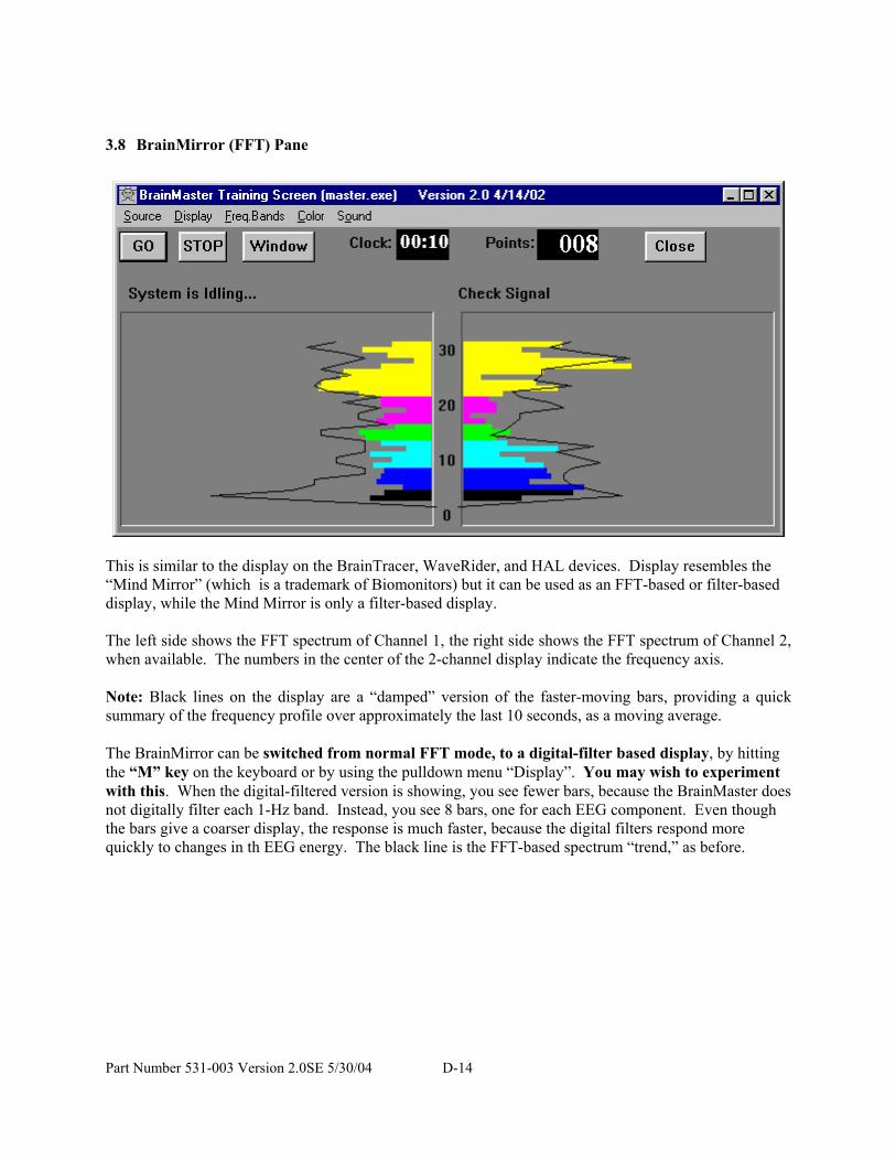
3.8 BrainMirror (FFT) Pane
This is similar to the display on the BrainTracer, WaveRider, and HAL devices. Display resembles the “Mind Mirror” (which is a trademark of Biomonitors) but it can be used as an FFT-based or filter-based display, while the Mind Mirror is only a filter-based display. The left side shows the FFT spectrum of Channel 1, the right side shows the FFT spectrum of Channel 2, when available. The numbers in the center of the 2-channel display indicate the frequency axis. Note: Black lines on the display are a “damped” version of the faster-moving bars, providing a quick summary of the frequency profile over approximately the last 10 seconds, as a moving average. The BrainMirror can be switched from normal FFT mode, to a digital-filter based display, by hitting the “M” key on the keyboard or by using the pulldown menu “Display”. You may wish to experiment with this. When the digital-filtered version is showing, you see fewer bars, because the BrainMaster does not digitally filter each 1-Hz band. Instead, you see 8 bars, one for each EEG component. Even though the bars give a coarser display, the response is much faster, because the digital filters respond more quickly to changes in th EEG energy. The black line is the FFT-based spectrum “trend,” as before.
Part Number 531-003 Version 2.0SE 5/30/04 D-14

3.9 BrainMirror (Filter) Pane
This pane shows a spectral display that uses the digital filters in place of the FFT. The example shown below is of a 2-channel display.
Part Number 531-003 Version 2.0SE 5/30/04 D-15

3.10 Coherence/Phase Pane
This pane shows the current coherence and phase values for any enabled components. It also shows the coherence or phase threshold. There is also an indicator within the threshold box that shows whether coherence or phase are being uptrained (“+”) or downtrained (“-“). It is possible to watch the threshold change by watching this box. Coherence threshold is increased by typing “c” on the keyboard. It can be decreased by typing “C” on the keyboard. Coherence is shown as colored bars, with 100% being full scale. Phase is shown using the small black lines, with 100% (180 degrees) being full scale. The numbers on the left of the coherence pane show the current coherence values in percent, for each component. The numbers on the right show the phase values, one for each component.
Part Number 531-003 Version 2.0SE 5/30/04 D-16

BrainMastertm System Type 2E Module & BMT Software for Windows
tm
Contributed Game Screens
1995 - 2004 BrainMaster Technologies, Inc., All Rights Reserved
“BrainMaster” and “From the Decade of the Brain” are registered trademarks of BrainMaster
Technologies, Inc. “Windows” is a trademark of Microsoft Corp.
U.S. Patent Number 5,899,867
Part Number 531-003 Version 2.0SE 5/30/04 D-C-1

1.1 Contributed Game Screens: There are several contributed game screens provided with the software. These are developed by independent developers, and contributed for general use. Cricket:
As training proceeds, the crickets “stack up” and pile on top of each other. Yes it is silly, but it is very popular.
Part Number 531-003 Version 2.0SE 5/30/04 D-C-2

Later on, the bottom images change, bonus points are awarded, and the screen becomes more interesting:
Bug Run: This screen provides a “bug race”. As the trainee meets the training criteria, the bugs will advance at random, running a race. If the trainee has excessive amounts of a “stop” component, some of the bugs will slip down a bit, and fall behind. The goal of the game is to have the race progress.
Part Number 531-003 Version 2.0SE 5/30/04 D-C-3

After awhile, one of the bugs will win, and be declared the winner:
Then the race will start over again, for continued training.
Part Number 531-003 Version 2.0SE 5/30/04 D-C-4

1.2 Extra Software: Additional software, as well a manual pages, web sites, and other useful items, may be accessed by pressing the “Browse” button under the “Additional Software” heading. This will produce a window that shows shortcuts to other programs, such as the following example:
These shortcuts are contained in the directory \brainm.20\extrasw, and the user can add any shortcuts to this folder, for convenient acccess.
Part Number 531-003 Version 2.0SE 5/30/04 D-C-5

Part Number 531-003 Version 2.0SE 5/30/04 D-C-6

BrainMastertm System Type 2E Module & BMT Software for Windows
tm
Popup Display Windows
for Master.exe
1995 - 2004 BrainMaster Technologies, Inc., All Rights Reserved
“BrainMaster” and “From the Decade of the Brain” are registered trademarks of BrainMaster
Technologies, Inc. “Windows” is a trademark of Microsoft Corp.
U.S. Patent Number 5,899,867
Part Number 531-003 Version 2.0SE 5/30/04 D-W-1

1. Accessory Windows This section describes the acccessory “windows” that can be launched from the BrainMaster training screen. These are independent windows that can be resized, minimized, maximized, and moved. They can even be dragged onto a second (or third) display monitor on computers that are equipped with more than one monitor. These programs are written using the BrainMaster “DLL” interface. They provide examples of the types of programs that can be written to this interface. We are also happy to show users how to write their own programs of this type. Most display windows can have their scale changed by using the “+” and “-“ keyboard keys. This will change the display scale to make the features larger or smaller, but will not change the EEG processing. Most display windows also accept typing input to adjust thresholds, in the same manner as the Training Screen. For example, “t” will increase the Theta threshold, and “T” will decrease it. They will not adjust the “targets” when using autothresholding, but will always adjust the thresholds themselves. They are useful for making temporary changes in thresholds, even when autothresholding is used. Simply type the appropriate key while one of the accessory windows is the “current” (top) window, to use this feature. All Windows can be activated using the Windows button on the Training Screen. This will bring up the Launch Window control:
1.1 Xwing Window
This window shows the “Xwing” game screen.
Part Number 531-003 Version 2.0SE 5/30/04 D-W-2
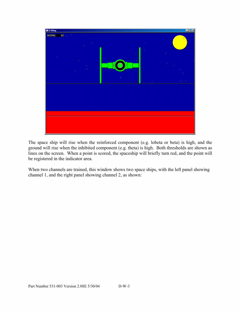
The space ship will rise when the reinforced component (e.g. lobeta or beta) is high, and the ground will rise when the inhibited component (e.g. theta) is high. Both thresholds are shown as lines on the screen. When a point is scored, the spaceship will briefly turn red, and the point will be registered in the indicator area. When two channels are trained, this window shows two space ships, with the left panel showing channel 1, and the right panel showing channel 2, as shown:
Part Number 531-003 Version 2.0SE 5/30/04 D-W-3

Part Number 531-003 Version 2.0SE 5/30/04 D-W-4

1.2 BrainMan Window
The following is the BrainMan training window.
The Brain-Man game runs in its own window, independent of the training screen. This window can be resized or moved. It can be moved to a second (or third, etc) monitor on a Windows 98 system that is equipped with multiple monitors. Brain--man will advance 1 point for each target "hit." Since the what constitutes a “hit” is determined by the setup of the Thermometer system, the exact criteria for causing the pac-man to move can be set up in any desired fashion, such as alpha-wave reinforcement, beta-wave reinforcement, etc. Whenever an inhibited component is over its threshold (such as theta), the Brain-Man will turn blue, signaling the trainee.
Part Number 531-003 Version 2.0SE 5/30/04 D-W-5

1.3 Numbers Window
This window shows the current values of the components.
This screen shows numeric values for each component. “Go” components are shown in green, “stop” components are shown in red, and others are shown in blue. The values are “damped” so they do not change too quickly. Thus provides a very useful display, for monitoring ongoing progress. This window can be sized to any desired size and shape. Ratios to theta can be shown by selecting the bottom text with the mouse:
Part Number 531-003 Version 2.0SE 5/30/04 D-W-6

In 2-channel mode it shows both channels:
Part Number 531-003 Version 2.0SE 5/30/04 D-W-7

1.4 Thermometer Window
This window shows enlarged thermometers with threshold information:
This window shows each of the major EEG component intensities as a bar graph with real-time response. This window is the foundation of the biofeedback reward method. Whether or not this window is being viewed, the thermometers and their associated controls define the operation of the biofeedback subsystem. Note that untrained (“ignored”) components will not appear in this window. The frequency bands are adjustable using the “Bsetup” program. Currently, they are set to the most accepted and useful ranges. The “temperature” of each thermometer reflects the amount of energy in the filter output for the respective frequency component. In addition to displaying the EEG energy in each band, the thermometers are used to set up the biofeedback paradigm, which includes which components to reward, or to discourage, and the threshold levels at which to elicit biofeedback signals. Each thermometer has a tic mark superimposed on it, with a number to the right. This mark and label indicate the current threshold for the detection of activity in that band. Threshold adjustment can then be accomplished by using the keyboard, typing for example, “t” to raise the theta threshold and “T” to lower it. The other components use their corresponding key letters, as shown below the thermometers. A “+” will appear in the lower center of the center bar, when a point is scored.
Part Number 531-003 Version 2.0SE 5/30/04 D-W-8

When two channels are used, two sets of thermometers appear, as shown:
Part Number 531-003 Version 2.0SE 5/30/04 D-W-9
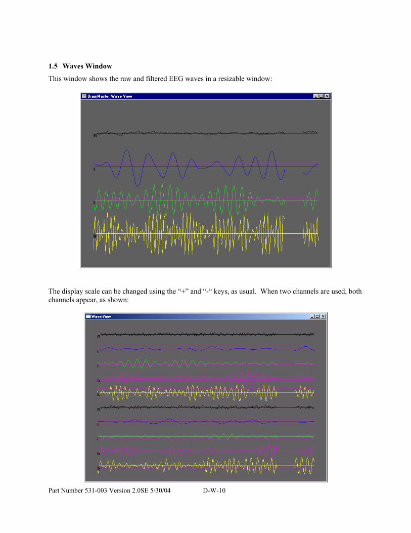
1.5 Waves Window
This window shows the raw and filtered EEG waves in a resizable window:
The display scale can be changed using the “+” and “-“ keys, as usual. When two channels are used, both channels appear, as shown:
Part Number 531-003 Version 2.0SE 5/30/04 D-W-10

1.6 BoxFlow Window
Similar to that used in other common displays - theta, SMR, and beta as 3 colored bars. The center bar is proportional to SMR, the left bar is proportional to theta, and the right bar is proportional to beta. Rectangular lines surrounding the boxes indicate the current threshold values. A “+” will appear in the lower center of the center bar, when a point is scored. When two channels are used, two “boxflows” appear, as shown:
Part Number 531-003 Version 2.0SE 5/30/04 D-W-11

1.7 BrainMirror Window
This window shows the BrainMirror in a resizable window. It uses the FFT to show the current EEG component values. Thresholds are also shown by the thin black lines.
The BrainMirror window also works in 2-channel mode:
Part Number 531-003 Version 2.0SE 5/30/04 D-W-12

1.8 Spectral Window
This window shows a “compressed spectral array”
This provides a cascade of past FFT spectra, covering the previous 1 minute of activity. Each frequency band is colored according to the frequency ranges selected. This coloring is the same as used on the FFT and the BrainMirror displays. There are tic marks and labels to identify the frequency coordinates of the display. When two channels are used, two spectra are shown:
Part Number 531-003 Version 2.0SE 5/30/04 D-W-13
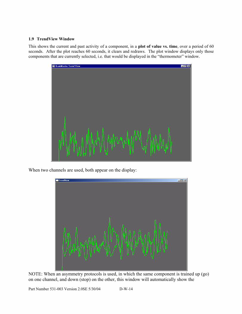
1.9 TrendView Window
This shows the current and past activity of a component, in a plot of value vs. time, over a period of 60 seconds. After the plot reaches 60 seconds, it clears and redraws. The plot window displays only those components that are currently selected, i.e. that would be displayed in the “thermometer” window.
When two channels are used, both appear on the display:
NOTE: When an asymmetry protocols is used, in which the same component is trained up (go) on one channel, and down (stop) on the other, this window will automatically show the
Part Number 531-003 Version 2.0SE 5/30/04 D-W-14

downtrained component in black, and the uptrained component in its normal color. The following display shows this window during alpha asymmetry training (“Asym” built-in protocol):
Part Number 531-003 Version 2.0SE 5/30/04 D-W-15

1.10 Circles Window
The Circles Window is similar to the Thermometers or BoxFlow, in that the center feature shows the main “uptrained” component, while the outer features show the high and the low “inhibits”. The amplitude of each component is shown by the size, and the color depth, of the respective circle. Threshold values are shown a white circles, which will be covered up (obscured) by the training circle, when it exceeds the threshold. The following screen shows this display window when using the “focus” protocol:
When two channels are used, this window adapts, to show the two “uptrained” components as an ellipse (width represents channel 1, and height represents channel 2. In addition, the total of 4 inhibits (2 each for the 2 channels) are shown at the corners. The channel 1 inhibits are shown on the left, and the channel 2 inhibits are shown on the right.
Part Number 531-003 Version 2.0SE 5/30/04 D-W-16

1.11 Dolphin Animation: The dolphin animation is included in 2.0 as a standard window. Press the “dolphin” button on the Windows control to activate this screen:
You will see the swimming dolphin. The dolphin will swim faster, the better the trainee is meeting the criteria:
Part Number 531-003 Version 2.0SE 5/30/04 D-W-17

1.12 Optional Animations: There are also a variety of optional animations. All animations are controlled using the NFViewer control bar. This bar will appear whenever you use the “Dolphin” start button, or the “AVI Viewer” start button, on the Launch Window control panel:
The AVI control panel is shown as follows: NOTE: the “browser” button with the folders shown may look different on your version of Windows. It will still function as intended, even if it looks different on the control panel. Location of “browser” button | V
If you have optional animations, you will have the “browser” button at the top left of this control. It is located to the right of where the “GO” button appears, as shown in the following example. If you press the “browser” button, you will see a selector control as follows:
Part Number 531-003 Version 2.0SE 5/30/04 D-W-18

Select the animation you want to see, and then press “OK”, then press the “GO” button that will appear on the control tool:
The following is an example of one of the additional animations, “flyby1”.
Part Number 531-003 Version 2.0SE 5/30/04 D-W-19