
tyco/ Healthcare kENDALL KANGAROO ePump · Section V - Instructions for Use ... Use buttons on left...
42
kENDALL KANGAROO ePump * Enteral Feeding Pump tyco/ Healthcare Enteral Feeding Pump Operation and Service Manual Enteral Feeding Pump Operation and Service Manual Enteral Feeding Pump Operation and Service Manual Enteral Feeding Pump Operation and Service Manual Operation and Service Manual See Instructions ����
-
Upload
hoangthien -
Category
Documents
-
view
222 -
download
1
Transcript of tyco/ Healthcare kENDALL KANGAROO ePump · Section V - Instructions for Use ... Use buttons on left...

kENDALL
KANGAROO ePump*Enteral Feeding Pump
tyco/ Healthcare
Enteral Feeding Pump Operation and Service Manual
Enteral Feeding Pump Operation and Service Manual
Enteral Feeding Pump Operation and Service Manual
Enteral Feeding Pump Operation and Service Manual
Operation and Service Manual
See Instructions����


Thank you for purchasing the KANGAROO ePump* Enteral Feeding Pump. With proper care, this device will provide you with years of precision service.
Table of Contents PageSection I - General Information ........................................................................ 1Section II - Safety and Warnings ...................................................................... 3Section III - Icon Identification ......................................................................... 4
Section IV - Initial Setup Attaching the A/C Adapter Power Cord ........................................................................................................5 Battery Setup ...............................................................................................................................................5
Attaching Pole Clamp ..................................................................................................................................6
Section V - Instructions for Use Quick Start ...................................................................................................................................................7
General Startup ...........................................................................................................................................8
Placement/Mounting ............................................................................................................................8
A/C Power Operation .............................................................................................................................8
Battery Power Operation ........................................................................................................................8
Power On/Off .......................................................................................................................................8
Keep or Clear Prior Pump Settings ...........................................................................................................8
Loading Pump Sets ......................................................................................................................................9 Prime Pump ...............................................................................................................................................10 Auto Priming ......................................................................................................................................11 Hold-To-Prime ...................................................................................................................................11
Re-priming after Bag Empty .................................................................................................................11
Selecting Continuous or Intermittent Feed Mode .......................................................................................12
Continuous Mode (Adjust Feed) .................................................................................................................12
Continuous Mode Feeding ...................................................................................................................12
Continuous Mode Flushing ...................................................................................................................13
Intermittent Mode (Adjust Bolus) ..............................................................................................................14
Intermittent Mode Feeding ...................................................................................................................14
Intermittent Mode Feeding - Bolus Max .................................................................................................15
Intermittent Mode Flushing ..................................................................................................................15
Run ............................................................................................................................................................16
Hold .................................................................................................................................................17
TABLE OF CONTENTS
KANGAROO ePump *

Table of Contents Page Flush Now .........................................................................................................................................18
More Options .............................................................................................................................................19
Buzzer Alarm Volume .........................................................................................................................19
History ..............................................................................................................................................19
Language Selection .............................................................................................................................19
Continuous/Intermittent Mode .............................................................................................................19
BioTech Menu .............................................................................................................................................20
Accessing the BioTech Screen ................................................................................................................20
BioTech Screen Data ............................................................................................................................20
Lock Settings Feature (Program Locked) .................................................................................................20
Lock Screen Feature ......................................................................................................................................................21
Section VI - Re-Certification of Performance System Performance Re-Certification ........................................................................................................21
Certifying the Accuracy of Pump Flow Rate ................................................................................................22
Section VII - Cleaning .................................................................................... 22 Section VIII - Battery Replacement ................................................................ 24Section IX - Error/Warning/Informational Screens and Troubleshooting System Error ...............................................................................................................................................25
Hold Error ...................................................................................................................................................26
Rotor Error .................................................................................................................................................27
Feed Error ..................................................................................................................................................27
Flush Error ..................................................................................................................................................27 Flow Error ..................................................................................................................................................28
Pump Set Dislodged Error ..........................................................................................................................28
Battery Low ...............................................................................................................................................29
Feeding Complete ......................................................................................................................................29
Pump Set Use >24 Hours Warning .............................................................................................................29
LED Array ...................................................................................................................................................29
Section X - Specifications and Symbols Specifications .............................................................................................................................................30
Symbols on Pump and Accessories .............................................................................................................32
Section XI - Customer Service ......................................................................... 33
KANGAROO ePump *

KANGAROO ePump
Table of Contents PageSection XII - Maintenance Side Door Enclosing Pump Set Loading Area ..............................................................................................33 Battery Pack ...............................................................................................................................................33
Battery Door ..............................................................................................................................................33
Power Cord .................................................................................................................................................33 Pole Clamp .................................................................................................................................................33
Section XIII - Service Part Numbers ................................................................ 34
Section XIV - Warranty ................................................................................... 34
Section XV - Electromagnetic Conformity Declaration ...................................... 35


1
Section I - General Information
The KANGAROO ePump enteral feeding pump is a simple-to-use, precision enteral feeding pump. It is easily programmed
to provide patients with either continuous or intermittent feeding, and can provide automatic flushing capability when
used with KANGAROO ePump Feed & Flush Sets.
User Interface:
• Intuitive user interface
• Large, backlit LCD display
• Step-by-step prompts to guide programming and operation
• “Stoplight” LED array visually indicates pump status in a bright or darkened room
Ergonomics:
• Quiet operation
• Compact, aesthetic design
• Tabletop usage or IV pole mounting
• Simple loading of Pump Sets
• Transparent side door to protect Pump Set
• Integrated handle for easy transport
Features:
• MISTIC (Magnetic Intelligent Set Type Identification Connector) Feed-Only vs. Feed & Flush Set identification system to
ensure match between the pump’s user interface and Pump Set type
• Automatic Anti-Free-Flow (AFF) System
• Audible alarm to indicate errors or Pump Set loading conditions
• Attitude-independent design eliminates need for drip chamber on pump set
• Sensor technology detects both upstream and downstream flow conditions
• Continuous feed, intermittent feed, and flush capability
• Auto-prime feature reduces the need for time-consuming manual priming
• Hold feature with programmable restart
• Stores previous 72 hours of feeding and flushing history
Service:
• Serial I/O port for data retrieval and software updates
• Uses replaceable, rechargeable NiMH Battery Pack for 15 hours of backup power
• Removable Power Cord
• Removable Pole Clamp
KANGAROO ePump *

2 KANGAROO ePump *
Figure 1A. KANGAROO ePump features, front and rear views.

3KANGAROO ePump *
Section II - Safety and Warnings
CAUTION: U.S. federal law restricts the sale of this device to physicians or to their direct representatives. 1. Read this booklet thoroughly before using the KANGAROO ePump enteral feeding pump. 2. Do not use this device near flammable anesthetics. 3. Disconnect power supply before cleaning or servicing. 4. Use only KANGAROO ePump enteral feeding pump Power Cord (with built-in A/C adapter) with pump. See
Section XIII - Service Part Numbers for replacement of Power Cord. 5. Use only KANGAROO ePump enteral feeding pump Pump Sets with this device. Pump is not compatible with other
Pump Sets. 6. For re-certification, see Section VI - Re-certification of Performance.
For other integrity checks, consult with a qualified Biomedical technician or contact the manufacturer (Section XI - Customer Service).
7. For service or for technical information, please contact Customer Service (Section XI).
8. Do not open the main housing, as there are no user-serviceable parts inside. Opening may affect function of device and voids the warranty. To replace battery, see Section VIII.
9. Dispose of old battery-powered electronic equipment in a manner consistent with institutional policy for expired equipment disposal.
Figure 1B. KANGAROO ePump Pump Set loading area.

4
10. Cleaning frequency and practices must be consistent with institutional policy for cleaning of non-sterile devices. See
Section VII - Cleaning, for instructions on cleaning the KANGAROO ePump enteral feeding pump.
11. See icon descriptions in Section III-Icon Identification and Section X - Specifications and Symbols for additional safety information.
12. This device is designed to minimize the effects of uncontrolled electromagnetic interference and other types of interference from external sources. Avoid use of other equipment that may cause erratic operation or degradation in
the performance of this device.
13. WARNING: The DB9 serial I/O port (see Figure 1A) is intended only for use by the manufacturer.
Any accessory equipment that can be connected to the DB9 Serial I/O port, and which does not comply with the
equivalent safety requirements of this equipment, may lead to a reduced level of safety of the pump. While use of
the pump’s DB9 port is not recommended for customers, the following should be considered in the event that the
customer decides to connect to this port:• The accessory is specifically certified as complying with the safety requirements for accessories used with the pump,
whereas the safety certification of the accessory has been performed in accordance to the appropriate IEC 60601-1 and/or IEC 60601-1-1 harmonized national standard.
• Under no circumstances should the certified accessory be used while the pump is in use for enteral feeding of a patient.
Section III - Icon Identification
Run Mode
Vertically-moving droplet in RUNNING screen indicates Run mode.
Battery Symbols
• Full charge• 2/3 or less charge • 1/3 or less charge
• Very low battery (15 minutes max.)
Auto Priming Indicator When auto priming, the bar will progress to show auto prime feature is active.
Volume Setting
Indicates alarm volume setting.
KANGAROO ePump *KANGAROO ePump *

5
Error Indicator
Pump operations are stopped until the error is resolved.
Information Indicator
This indicates information only, and does not require any immediate action.
Section IV - Initial Setup
Attaching the A/C Adapter Power Cord
Plug the Power Cord into the A/C Adapter Port on the back of the pump. See Figure 1A to locate port on pump. Make note of the location of the pins and tab on the plug to properly orient the plug.
KANGAROO ePump *KANGAROO ePump *
The connector, which attaches to the back of the pump, has a spring-loaded locking sleeve that locks into the pump, thus helping to prevent the connector from being accidentally knocked out. To remove the connector, grasp the outer, sliding sleeve member and pull. Do not detach the connector by pulling on the wire only.
Battery Setup
The battery pack is fully charged before shipping, and is left unconnected to optimally preserve battery life.
WARNING: The battery should be connected before using the pump.
It is also recommended that the battery charge be “topped off” before battery-only operation is utilized. The battery pack will charge continuously whenever the pump is plugged into a wall outlet, including during normal use of the pump with A/C power. Eight hours of charging is required to fully recharge the battery pack.
A new battery pack will provide approximately 15 hours of service before needing to be recharged.
Figure 2. Alignment ofA/C Adapter plug withpump’s adapter port.

6
Attaching Pole ClampThe KANGAROO ePump enteral feeding pump can be attached to a vertical pole using the Pole Clamp, included with the pump.
To attach the Pole Clamp to the KANGAROO ePump enteral feeding pump, align the hole on the Pole Clamp with the mounting hole on the back of the pump. Use a 3/8” round head bolt and rubber washer to fasten together, as shown in Figure 3.
KANGAROO ePump *KANGAROO ePump *
Figure 3. Attaching and using the Pole Clamp.

7
Section V - Instructions For Use
Quick Start
1. Press POWER on lower, right-hand corner of control panel.
2. Open blue door enclosing Pump Set loading area.
3. To load Pump Set (refer to Figure 4):
• Grasp finger tab on valve and insert into left pocket (1).
• Grasp black ring retainer and gently stretch tubing around rotor (2). Pull up on retainer and insert into right
pocket (3).
• Press down on finger tab to ensure that valve is fully seated.
• Close blue door.
(Note: display status line should read SET LOADED).
4. To automatically prime the pump, pressPRIME PUMP andAUTO PRIME. For Feed & Flush sets, auto priming
will prime both lines.
5. To directly control pump priming, pressPRIME PUMP and then press and hold the HOLD TO PRIME
button(s). If a Feed & Flush Set is used, remember to first pressHOLD TO PRIME FLUSH until the flushing
fluid has reached the valve, and then pressHOLD TO PRIME FEED until the feeding fluid has reached past the
valve and down to the distal end connector.
6. Use buttonson left side of LCD to set the feeding parameters. Set flushing parameters if a Feed & Flush Set is
loaded. The continuous or intermittent feed mode selection is made under the MORE options menu.
7. PressRUN when ready to start. The screen will display RUNNING.
8. To stop, pressHOLD or press and hold the POWER button.
KANGAROO ePump *KANGAROO ePump *
Figure 4. Installation of Pump Set.
1 3
2
Black RingRetainer(MISTIC)
FingerTab
Valve
Rotor
8
General Startup
Placement/Mounting
There are two recommended placement methods for the KANGAROO ePump enteral feeding pump.
• Attached to a vertical IV pole via the Pole Clamp peripheral device, included with the pump.
• Placed feet down on any horizontal surface.
A/C Power Operation
Plug the KANGAROO ePump enteral feeding pump into an A/C power outlet for normal operation. When the pump is
not plugged in, or if A/C power is interrupted, a built-in rechargeable battery will run the pump.
Battery Power Operation
If A/C power is not available to the pump, or if A/C power is interrupted, the pump will automatically operate on
backup battery power. The built-in battery recharges any time the pump is plugged into an outlet.
A fully-charged, new battery will supply 15 hours of backup power at 125 ml/hr before requiring recharging. Contact
Customer Service, Section XI, to replace the Battery Pack if battery life degrades.
Power On/Off
To power up the pump, press the POWER button on the lower right of the front panel. To power down the
pump, press and hold the POWER button until the pump display turns off.
Keep or Clear Prior Pump Settings
Immediately after powering up the pump, if the prior feed or flush settings were not cleared and the settings are not
locked in the BioTech Screen, the pump will give the following two options:
KEEP SETTINGS - Select this option to start with the same settings that were most recently programmed
into the pump. Any of the previously-programmed settings can be modified, if needed. The feed totals,
“mL FED” (Continuous Feed mode) or “BOLUSES FED” (Intermittent Feed Mode) are also maintained.
CLEAR SETTINGS - Select this option to reset all input feeding settings to zero. It will then be necessary to
program all settings before running the pump. Note that only input settings are cleared. The feed totals,
“mL FED” (Continuous Feed mode) or “BOLUSES FED” (Intermittent Feed Mode) will not be reset to zero.
To clear output feed totals, “mL FED” or “BOLUSES FED”:
• Program the input settings
• Start the pump RUNNING
• Immediately press the HOLD button.
• Select the top button, CLEAR VOL. FED
The status line of the pump will then show LOAD A SET (Figure 5), or, if the Pump Set is already loaded, it will show SET LOADED (Figure 7).
KANGAROO ePump *KANGAROO ePump *

9
Loading Pump Sets
The KANGAROO ePump enteral feeding pump will indicate LOAD A SET in the screen’s status line if a Pump Set is not
installed. A blinking icon of a Pump Set will also appear in the upper left corner of the screen. Figure 5A shows the
screen for continuous feeding mode and Figure 5B shows the screen for intermittent feeding mode.
KANGAROO ePump *KANGAROO ePump *
To load a Pump Set, follow the steps below:
1. Open the blue transparent door that encloses the rotor and Pump Set loading area.
2. Load the Pump Set by holding the finger tab on the valve, and inserting the valve down into the slot on the left.
(Figure 6A)
3. Grasp the MISTIC retainer end (black ring retainer) and wrap the tubing counterclockwise around the rotor.
(Figure 6B)
4. Carefully pull the MISTIC retainer end upwards to position it over the slot on the right, and then lower the retainer into
the slot. (Figure 6B)
5. Press down on the valve’s finger tab to ensure proper seating.
6. Close blue transparent door.
Figure 5A. LOAD A SET opening menu screen for Continuous Feeding mode.
Figure 5B. LOAD A SET opening menu screen for Intermittent Feeding mode.
Figure 6A. Figure 6B.

10
The display should read SET LOADED and will show one of the following opening menus, depending on the type of
Pump Set detected, and whether continuous or intermittent feeding mode has been selected.
Prime Pump
The KANGAROO ePump enteral feeding pump may be primed automatically with a single button push, including the
flushing line if a Feed & Flush Set is loaded. The pump can also be primed in a more interactive method using the hold-
to-prime feature.
After a Pump Set has been loaded and the status line shows SET LOADED, pressPRIME PUMP in the opening menu
(Figure 7) to get one of the PRIME PUMP menus shown in Figure 8.
Figure 7A. Opening menufor Continuous Feed modewith a Feed-Only set.
Figure 7B. Opening menufor Continuous Feed modewith a Feed & Flush set.
Figure 7C. Opening menufor Intermittent Feed mode with a Feed-Only set.
Figure 7D. Opening menufor Intermittent Feed modewith a Feed & Flush set.
Figure 8A. PRIME PUMPmenu for Feed-Only set.
Figure 8B. PRIME PUMPmenu for Feed & Flush set.
KANGAROO ePump *KANGAROO ePump *

11KANGAROO ePump *KANGAROO ePump *
Auto Priming
The AUTO PRIME option will be available if the pump senses that the currently installed Pump Set was not
previously primed, and that there is no fluid in the line near the rotor. If auto-priming is desired, press and
releaseAUTO PRIME to automatically prime the line(s). For Feed & Flush Pump Sets, the auto prime feature will
automatically prime both lines, starting with the flush line.
Press STOP to cancel AUTO PRIME.
When auto-priming is completed, the status line will show AUTO PRIME COMPLETE and will no longer show the
AUTO PRIME option. Be sure that the line(s) are fully primed. If not, use the hold-to-prime option(s) to complete
the priming, as described below.
Hold-to-prime
The hold-to-prime options allow for precise interactive control of the priming process.
Feed-Only Pump Sets
For Feed-Only Pump Sets, the screen will appear as in Figure 8A. Press and holdHOLD TO PRIME FEED until the feed line has been primed down to the stepped end connector at the end of the Pump Set.
Feed & Flush Pump Sets
For Feed & Flush Pump Sets, the display will appear as in Figure 8B. First press and holdHOLD TO PRIME FLUSH to prime the flushing line, and then press and holdHOLD TO PRIME FEED to prime the feed line down to the stepped end connector at the end of the Pump Set.
If a Feed & Flush Pump Set is used, remember to first pressHOLD TO PRIME FLUSH until the flushing fluid has reached the valve, and then pressHOLD TO PRIME FEED until the feeding fluid has reached past the valve and down to the stepped end connector. If the feeding line is primed first, subsequent priming of the flushing line will force the air between the flush solution bag and valve into the main line, which already has been primed with enteral formula.
Re-priming after Bag Empty A Pump Set bag that has been emptied will trigger the FEED ERROR screen. In this condition the Pump Set bag can be refilled to continue the feeding, but only after the Pump Set has been re-primed.
To re-prime the Pump Set, do the following: • Disconnect the feeding line from the patient • Refill the bag • PressCONTINUE to begin the pump RUNNING • PressHOLD • PressADJUST SETTINGS • PressHOLD TO PRIME to prime the line(s)
Pump Sets should not be reused after 24 hours of initial usage.

12
Continuous Mode (Adjust Feed)
Continuous Mode Feeding
For CONTINUOUS feeding mode, the ADJUST FEED option is available in the opening menus (Figure 7A for
Feed-Only sets or Figure 7B for Feed & Flush sets). Select this option to program the feeding parameters from the
ADJUST FEED screen, Figure 10A.
PressFEED RATE in Figure 10A to define the rate of delivery. Press thebuttons in Figure 10B to program the
rate from 1 to 400 in increments of 1 ml/hr. PressENTER (top button) to exit the menu.
PressFEED VTBD in Figure 10A to define the Volume To Be Delivered. Press thebuttons in Figure 10C to
program the volume from 1 to 3000 ml in increments of 1 ml. PressENTER (top button) to exit the menu. If the
FEED VTBD is set to zero, the pump will run until the bag is emptied.
Figure 9A. MORE OPTIONS menu. Figure 9B. SELECT MODE menu for continuous or intermittent mode selection.
KANGAROO ePump *KANGAROO ePump *
Selecting Continuous or Intermittent Feed Mode
The KANGAROO ePump enteral feeding pump can be programmed to feed continuously or intermittently.
The continuous feeding mode will deliver the enteral nutrition at a steady rate, either until the programmed volume has
been delivered or until the supply has been exhausted. The Intermittent feeding mode delivers boluses of enteral nutrition
at programmed time intervals. The bolus volume and feed rate are also programmed.
To select continuous feed mode or intermittent feed mode, pressMORE on the opening menu, shown in Figures
5 or 7, to access the MORE OPTIONS menu, Figure 9A.
The MORE option is available either before a Pump Set has been loaded (Figure 5) or after the Pump Set is loaded
(Figure 7). See subsection “More Options” for information on the other options in the MORE OPTIONS menu.
SelectCONTINUOUS/INTERMITTENT under the MORE OPTIONS menu, Figure 9A. Then press
CONTINUOUS MODE orINTERMITTENT MODE from the SELECT MODE menu, Figure 9B. PressDONE to
exit.

Figure 10A. ADJUST FEED menu. Figure 10B. Setting the Feed Rate.
Figure 10C. Setting the Feed Volume to be Delivered.
13
Continuous Mode Flushing
For CONTINUOUS feeding mode with a Feed & Flush Set loaded, the opening menu will appear as shown in
Figure 7B. PressADJUST FLUSH in Figure 7B to program the flushing parameters from the ADJUST FLUSH
screen, shown in Figure 11A.
PressFLUSH VOLUME in Figure 11A to define the volume per flush occurrence. Press thebuttons in
Figure 11B to program the flush volume from 10 to 500 in increments of 1 ml. PressENTER (top button) to exit
the menu.
PressFLUSH INTERVAL in Figure 11A to define the time interval between starts of flushing. Press thebuttons
in Figure 11C to program the time interval from 1 to 24 hours in increments of 1 hour. PressENTER (top button) to
exit the menu.
The pump will automatically limit flushing settings which exceed pump capabilities to deliver.
CAUTION: The KANGAROO ePump enteral feeding pump flushes at a rate of 1960 mL/hr (32.7 mL/minute). Use
care when programming the flush volume so that it matches the patient’s need.
NOTE: The pump will automatically flush an additional 25 ml of water after completing the programmed delivery of
formula, as long as at least one flush had occurred during formula delivery.
KANGAROO ePump *KANGAROO ePump *
Figure 11A. ADJUST FLUSHmenu, continuous mode.
Figure 11B. Setting the Flush Volume.
Figure 11C. Setting the Flush Time Interval.

14
Intermittent Mode (Adjust Bolus)
Intermittent Mode Feeding
For INTERMITTENT feeding mode, the ADJUST BOLUS option is available in the opening menus (Figure 7C for a
Feed-Only set or Figure 7D for a Feed & Flush set). Select this option to program the feeding parameters from the
ADJUST BOLUS screen, Figure 12A.
PressBOLUS RATE in Figure 12A to define the rate of delivery. Press thebuttons in Figure 12B to program the
delivery rate from 1 to 400 in increments of 1 ml/hr. PressENTER (top button) to exit the menu.
PressNUMBER OF BOLUSES in Figure 12A to define the total number of boluses to be delivered. Press the
buttons in Figure 12C to program the number of boluses, up to a maximum of 99. PressENTER (top button) to
exit the menu. The number of boluses can be set as zero, in which case the pump will run until the bag is emptied.
PressVOLUME PER BOLUS in Figure 12A to define the Volume to be delivered in each bolus. Press
thebuttons in Figure 12D to program the volume per bolus from 1 to 1000 ml in increments of 1 ml.
PressENTER (top button) to exit the menu.
PressBOLUS INTERVAL in Figure 12A to define the time interval between starts of bolus deliveries. Press
thebuttons in Figure 12E to program the time interval between starts of bolus deliveries from 1 to 24 hours in
increments of 1 hour. PressENTER (top button) to exit the menu.
The pump will automatically limit bolus settings which exceed pump capabilities to deliver. For example, a bolus
delivery volume of 200 mL cannot be made once per hour if a rate of 150 mL/hr is already programmed. In this case,
the maximum volume allowed would be 150 mL.
KANGAROO ePump *KANGAROO ePump *

Figure 12A. ADJUST BOLUS menu.
Figure 12B. Setting the Bolus Rate.
Figure 12C. Setting the Number of Boluses.
Figure 12D. Setting the volume per Bolus.
Figure 12E. Setting the time interval between starts of bolus.
15KANGAROO ePump *KANGAROO ePump *
Intermittent Mode Feeding - Bolus Max
The BOLUS MAX option can be used to deliver a bolus at a high rate, similar to gravity feeding. PressBOLUS MAX in the BOLUS RATE menu, Figure 12B, to program the BOLUS MAX mode. The feeding rate in Figure 7
will show “999” during RUNNING, indicating that the high feed rate is active.
Intermittent Mode Flushing
For INTERMITTENT feeding mode with a Feed & Flush Set, the opening menu, shown in Figure 7D, will show the
ADJUST FLUSH option. PressADJUST FLUSH in Figure 7D to program the flushing parameters from the
ADJUST FLUSH screen, Figure 13A.

16
Note: The nature of two intermittent processes, periodic bolus feeding and periodic flushing, is such that occasional conflicts can arise where each process needs to be running at the same time. Because the Feed-Only type of Pump Set is available, and is dedicated only to feeding, the flushing process is assigned precedence over the feeding process for Feed & Flush pump sets. “Flushing precedence” means that a flush cycle will run to its end even if a bolus delivery is scheduled to begin. It also means that a flush cycle will interrupt a bolus feeding cycle that is already in progress. The feeding cycle will pick up where it was interrupted after the flushing cycle is complete. It is therefore possible that the net feeding volume is reduced from what may be intended, over a given time period.
PressFLUSH VOLUME in Figure 13A to define the volume per flush cycle. Press thebuttons in Figure 13B to program the flush volume from 1 to 500 in increments of 1 ml. PressENTER (top button) to exit the menu.
PressFLUSH INTERVAL in Figure 13A to define the time interval between starts of flushing. Press thebuttons in Figure 13C to program the time interval from 1 to 24 hours in increments of 1 hour. PressENTER to exit the menu.
The pump will automatically limit flushing settings which exceed pump capabilities to deliver.
CAUTION: The KANGAROO ePump enteral feeding pump flushes at a rate of 1960 mL/hr (32.7 mL/minute). Use
care when programming the flush volume so that it matches the patient’s need.
NOTE: The pump will automatically flush an additional 25 ml of water after completing the programmed delivery of
formula, as long as at least one flush had occurred during formula delivery.
Run
The KANGAROO ePump enteral feeding pump will only run when a Pump Set is properly loaded and the necessary
feeding parameters have been programmed. For a Feed & Flush Set, the flushing parameters do not have to be set for the
pump to begin operating. If flushing parameters are set as zeros, there will be no flushing.
After the pump has been programmed, pressRUN to start operation. Figure 14 shows the RUNNING screen for
continuous feeding with flushing. The status line will indicate RUNNING, and the droplet icon will move vertically on
the screen. The green LED indicator will be illuminated to give a quick visual indication of positive status in a darkened
room.
KANGAROO ePump *KANGAROO ePump *
Figure 13A. ADJUST FLUSHmenu, intermittent mode.
Figure 13B. Setting the Flush Volume.
Figure 13C. Setting the Flush Time Interval.

Figure 14. RUNNING mode screen for continuous feed mode.
17KANGAROO ePump *KANGAROO ePump *
Hold
Pump operation can be paused by pressingHOLD while it is RUNNING, such as in Figure 14. The status line will indicate HOLDING and the yellow LED indicator will be lit up to give a quick visual indication of a warning status in a darkened room.
Note: the pump’s alarm will sound if it has been left HOLDING for 10 minutes without further input. It can be programmed to automatically restart after a specified time period by pressing theRESUME IN ___ MIN. button.
There are five options available during HOLDING. See Figures 15A and 15B.
Figure 15A. HOLDING mode options, continuous feeding mode.
Figure 15B. HOLDING mode options, intermittent feeding mode.
The RUN option can be selected from the following screens, if the proper parameters are programmed and the Pump Set
is loaded:
• SET LOADED screens (Figure 7)
• ADJUST FEED screen, continuous mode (Figure 10A)
• ADJUST FLUSH screens (Figure 11A, 13A)
• HOLDING screens (Figure 15)

18
Clear Volume Fed
PressCLEAR VOL FED to re-zero the mL FED output status on the right side of the screen of Figure 15A,
or to re-zero the BOLUSES FED output status in Figure 15B.
Adjust Settings
Press ADJUST SETTINGS to return to one of the opening menus shown in Figure 7, thus allowing any
setting to be modified. If the Pump Set has been removed after going into HOLD, the opening menu will
show LOAD A SET, as seen in Figure 5.
Resume After Specified Time Interval
PressRESUME IN __ MIN to immediately input a time in minutes in which to resume operation. Each
press of RESUME IN MIN will increment the resume time by 5-minute increments, up to 30 minutes.
After “30” is reached, each additional button press will increment in larger time steps, up to a maximum of 240
minutes. No other input is needed to start the countdown, as the time immediately counts down after the
incremental value is reached.
Run Mode
PressRUN to immediately restart pump operation. This option will not be available if the Pump Set is
removed during HOLD.
View History
PressHISTORY to access the HISTORY screen. Use this screen to review feeding and flushing history.
See subsection “More Options” below for further information.
Flush Now
During the RUNNING mode, the pump can be diverted to immediately perform a flush (flush on demand) by
pressingFLUSH NOW in the RUNNING menu. See Figure 14. WhenFLUSH NOW is pressed, the screen
will prompt for the volume to be immediately flushed, and will show the previously programmed flush volume as
default. The screen will appear as the standard Flush input screen as shown in Figure 11B (or 13B). Setting
the FLUSH NOW flushing volume is temporary and will not change the main/periodic flushing volume previously
programmed. IfFLUSH NOW is pressed by accident, the screen will return to the RUNNING screen after 10
seconds, if there is no input for the flush volume.
KANGAROO ePump *KANGAROO ePump *

Figure 16. MORE OPTIONS menu.
Figure 17. Feed and Flush totals for up to 72 hours of previous history, excluding data from the current hour.
19KANGAROO ePump *KANGAROO ePump *
More OptionsPressMORE in one of the opening menus, Figures 5 or 7, to access the MORE OPTIONS screen, Figure 16.
Language Selection
PressLANGUAGES in the MORE OPTIONS menu to change the preferred language for the screen interface.
Continuous/Intermittent Mode
PressCONTINUOUS/INTERMITTENT In the MORE OPTIONS menu to access the SELECT MODE menu,
Figure 9B. Use this menu to select between continuous feeding mode and intermittent feeding mode. See subsection
“Selecting Continuous or Intermittent Feed Mode” for more information.
PressDONE in the MORE OPTIONS menu to exit the menu.
Buzzer Alarm Volume
PressBUZZER in the MORE OPTIONS menu to access the BUZZER screen and increase or decrease the alarm buzzer volume. The alarm will be audible as the volume setting is changed. This sets the volume level for any warning or error that may occur with the pump.
History
PressHISTORY in the MORE OPTIONS menu to access the HISTORY screen. Press thebuttons in Figure 17 to set the time history of interest. The totals of FEED mL and FLUSH mL will be shown for the requested history time.
WARNING: A maximum of 72 hours of past history can be retrieved, excluding data from the current hour.

20
BioTech Screen Data
SN is the serial number of the pump.
SW shows the software version number in this pump.
FLASH shows the version number of the flash data installed in this pump.
CERT INTV indicates the number of times the pump has been powered on since the last re-certification. See
Section VI for details of re-certifying the pump.
Lock Settings Feature (Program Locked)
To “lock” the settings against unauthorized changes, pressLOCK SETTINGS to get the check mark, as shown in
Figure 18. The settings can only be changed again by pressingLOCK SETTINGS to remove the check mark. If the settings are locked and a change is attempted, the screen will indicate PROGRAM LOCKED, and will not allow access to the parameters, Figure 19.
The pump can be PRIMED or set to RUN, HOLD, etc. when settings are locked.
PressDONE to exit the BioTech menu. To re-enter this menu screen, power down the pump and then power it up again and hold the topbutton, as described above.
KANGAROO ePump *KANGAROO ePump *
Figure 18. BioTech screen, with Pump Settings “locked” against unauthorized changes.
BioTech Menu
The BioTech screen will show technical information about the pump, and has a lock feature to lock the Pump Settings
against unauthorized changes.
Accessing the BioTech Screen
To get the BioTech screen, press the power button to start the pump, and press and hold the topbutton while the startup sequence (kangaroo icon “hops” across the screen) executes. You must be pressing the topbutton at the end of the sequence in order to access the BioTech menu. Figure 18 shows the BioTech screen.

Figure 19. Program Locked screen, which indicates the pump is in LOCK SETTINGS mode.
Figure 20. Padlock indicates pump is in LOCK SCREEN mode.
21KANGAROO ePump *KANGAROO ePump *
Lock Screen Feature
The KANGAROO ePump enteral feeding pump can be set to RUN and then locked out from unauthorized use. While the
LOCK SETTINGS feature prevents only changes to the input parameters, the LOCK SCREEN feature will lock out any
button presses, including RUN or HOLD, except power off.
Use LOCK SCREEN when the pump is running and there is a need to prevent tampering such as putting the pump into an
unwanted HOLD. The RUNNING screen will show a padlock to indicate that no changes can be made without unlocking
the screen.
To lock the screen, use the following procedure while the pump is in RUNNING mode:
• Press and hold the secondbutton from the top for at least 2 seconds.
• Press and hold the thirdbutton from the top for at least 2 seconds.
• Press and hold the secondbutton again for at least 2 seconds.
To unlock the screen, use the same procedure above.
Section VI - Re-Certification of KANGAROO ePump Performance
System Performance Re-Certification
A series of self-diagnostic checks can be run to re-certify pump performance. It is recommended that this
re-certification procedure be run at least once per year, or any time the pump is suspected of having improper
performance. See Section XIII-Service Part Numbers for ordering new Re-Certification Pump Sets.
Load the Re-Certification Pump Set. The pump will automatically recognize the Re-Certification Pump Set and give

22
brief instructions to initiate the self-diagnostic procedure. Follow the instructions and review the summary
information at the end of the test.
Certifying the Accuracy of Pump Flow Rate
Use the following procedure to check the flow rate accuracy:
• Perform test at room temperature (72° F ± 3° F) with a new Pump Set.
• Fully fill a new Feed-Only Pump set bag with water.
• Load the Pump Set.
• Suspend the Pump Set bag so that the bottom of the bag is 18 inches above the pump.
• Make sure pump is plugged into A/C power (do not run test with battery power).
• Program a Continuous Mode feed rate (see below for suggested example rates).
• Run the pump for 15 minutes to achieve steady state operation.
• Then begin collecting the water in a calibrated measuring container, such as a large-capacity graduated cylinder, for
exactly 30 minutes.
NOTE: The amount of water collected in 30 minutes will be half of the value programmed for the hourly flow rate, within ± 10%, or 0.5 ml, whichever is larger.
Rate Set Amount Expected in 30 Minutes
75 mL/hr 33.7 mL to 41.3 mL 150 mL/hr 67.5 mL to 82.5 mL
If the amount collected is outside the range, load a new Pump Set and re-run the test procedure to confirm results.
Section VII - Cleaning
Cleaning should be performed as needed. It may also be desireable to define cleaning intervals based on knowledge of the environment in which the pump is used. Only personnel trained in the cleaning of medical devices should perform cleaning.
CAUTION:
Do not immerse pump or power cord in water or other cleaning solution; clean using a damp (not wet) cloth or sponge. Failure to follow the cleaning procedures described herein could result in hazards to users. As with any AC powered electrical device, care must be taken to prevent liquid from entering the pump to avoid electrical shock hazard, fire hazard, or damage to electrical com-ponents.
If any of the following events occur, DO NOT USE the pump until it has been properly cleaned and serviced by
personnel trained in servicing KANGAROO ePump enteral feeding pumps: • wetting of the pump’s power cord or leakage into the pump interior during cleaning. • spillage of large amounts of formula onto the pump exterior, or any spillage onto the power cord.
KANGAROO ePump *KANGAROO ePump *

23KANGAROO ePump *KANGAROO ePump *
General Cleaning Directions
Cleaning of KANGAROO ePump enteral feeding pumps must be performed as follows:
CAUTION:
Disconnect pump from AC power source before cleaning. After cleaning, do not connect to AC power source until pump and power cord are thoroughly dry.
• A mild detergent should be used for general cleaning. If necessary, the pump may be cleaned with a 10:1 water and hypochlorite mixture, however, repeated cleaning with this solution can damage the plastic pump case. Isopropyl alcohol, applied with a damp (not wet) cotton swab, may be used for cleaning difficult-to-reach areas, however, it should be used sparingly because repeated cleaning may damage the case. • DO NOT USE strong cleaners such as †Spray-Nine, †Phisohex, †Hibiclens, or †Vesta-Syde because damage to the pump case housing can result.
Directions for Cleaning Pump Housing
• Refer to General Cleaning Directions before starting. • Clean outside surface with a damp (not wet) cloth or sponge and keep pump in upright position as much as possible. • Avoid excess moisture near pole clamp area. • Do not allow cleaning solution to enter the vertical vents in the housing, underneath the handle.
Directions for Cleaning Pump Power Cord
• Refer to General Cleaning Directions before starting. • Unless soiling is observed, the power cord should not be cleaned. • If cleaning of the power cord is necessary, unplug from outlet and wipe the exterior surfaces of the wall plug with a cloth dampened with isopropyl alcohol.
CAUTION:
Avoid exposing power cord to excess moisture, as this can lead to an electrical shock or fire hazard.
Directions for Cleaning Rotor Assembly
• Refer to General Cleaning Directions before starting.
• Open the blue door enclosing the Pump Set loading area.
• Loosen rotor set screw with 5/64” (2mm) allen wrench and gently pull rotor off shaft. After removing rotor, avoid
getting any moisture in the rotor shaft opening.
• Clean rollers thoroughly with warm soapy water, or isopropyl alcohol if necessary.
• Be sure all parts of rotor are completely dry before putting it back onto shaft.
• To replace rotor, align set screw on hub of rotor with the flattened section of the output shaft.
• Push rotor into place and tighten set screw (Do not over tighten).

24 KANGAROO ePump *
Preventative Maintenance
This pump must be periodically re-certified to assure proper functioning and safety. The recommended service interval is at least once per year. Re-certification may be done at the user’s Biomedical Engineering Department, an outside service, or by Tyco Healthcare Group LP Factory Service. To arrange for Tyco Healthcare Group LP Factory Service, call 1-800-448-0190. In Canada, call 1-877-664-TYCO(8926)
If a pump malfunctions, please contact your THGLP Representative or call Customer Service for instruction.
Section VIII - Battery ReplacementSee Figure 21 and do the following to replace the Battery Pack: • Power down the unit. • Loosen the Battery Door screw, on back of pump. • Open Battery Door and disconnect wire harness. A small straight-bladed screw driver may be needed to disconnect the connector tab. • Slide Battery Pack out of compartment. • Slide a new Battery Pack into compartment with wire harness extending out. • Align connector with red wire at upper right. • Push connector in until properly latched. • Tuck wires into slot between connector and battery to insure wires are not pinched. Re-tighten Battery Door screw.Note: Replacement Battery Packs are available from Tyco Healthcare/Kendall Co. (See Section XIII - Service Part Numbers).
WARNING: USE OF A BATTERY PACK NOT SUPPLIED BY TYCO HEALTHCARE/KENDALL CAN BE DANGEROUS AND VOIDS ALL WARRANTIES AND PERFORMANCE SPECIFICATIONS.
The battery will charge continuously whenever the pump is plugged into a wall outlet. Eight hours of charging is required to fully recharge the Battery Pack.
Figure 21. Installation of Battery Pack.

25KANGAROO ePump *
Section IX - Error/Warning/Informational Screens and Troubleshooting
For operational errors, the KANGAROO ePump enteral feeding pump display will show the error indicator icon, with
specific information regarding the error condition, and will sound the alarm.
The following conditions will trigger error conditions and will activate audible and visible alarms:
• Feed or Flush containers are empty
• Feed or Flush tube becomes occluded between bag and pump
• Tube becomes occluded between pump and patient
• Battery low (alarm sounds momentarily, about 15 minutes before shut-off)
• Unit is left in HOLD mode longer than 10 minutes without input
• Pump Set tubing is improperly loaded around the rotor
• System errors, see below
• Feeding complete
• The MISTIC connector is removed during AUTOPRIMING or RUNNING
The Error, Warning, and Information Screens are described below:
System Error
The system error screen is the most general form of error, Figure 22. The only way to exit from a System Error is to power
down. No CONTINUE option is allowed because of the severity of the error. An error number is also displayed on the
screen, for reference purposes. This number should be reported when calling the Customer Service Support Line.
Error # Related Sub-system
0 Internal timer stopped.
1 Flash Chip missing OR version incompatible.
2 Too many graphic screens in memory.
4 Never got a ADC ISR for motor current.
5 Never got a ADC ISR for battery level.
6 Never got a ADC ISR for battery temperature.
7 Never got a ADC ISR for Ultrasonic Upstream Occlusion or Bag-Empty checks.
8 Never got a ADC ISR for Ultrasonic during Downstream Occlusion.
9 RS232 Communications Transmit.
10 Flash Write Error.
11 Flash Read Error.
12 Stopcock Time Out.
13 Time Out for Buzzer Test

26 KANGAROO ePump *
Error # Related Sub-system
14 Time Out during downstream occlusion check, never got RotorOn3=0. May blow fuse.
20 Could not find Stop Cock Flush Position during prime routine.
21 Could not find Stop Cock Feed Position during prime routine.
22 Motor Error during Tubing AutoLoad.
23 Motor Failsafe Time Out Error. Possible damaged gearbox encoder or flex cable.
50 Graphic Display Error - Timeout during GDStatusCheck function.
51 Graphic Display Error - Timeout during GDAutoModeDataWriteCheck function.
52 Graphic Display Error - Timeout during GDWriteBytes function.
If the error cannot be resolved in a timely manner, press POWER to stop operation of the pump and put a different
pump into service.
Hold Error
The HOLD ERROR screen will appear if the pump has been in HOLD mode, without input, for more than 10 minutes.
See subsection “Hold” for description of HOLDING mode.
PressCONTINUE to return to the HOLDING screen, where settings can be adjusted, the pump can be set to run
immediately, or the pump can be set to run in a specified number of minutes. See Figure 15 to see the options on the
HOLDING menu screen.
If the error cannot be resolved, press POWER to stop operation of the pump and put a different pump into service.
Figure 22. General System Error screen. See Customer Service section.
Figure 23. Hold Error screen.

Rotor Error
The ROTOR ERROR screen appears during RUNNING or PRIMING, when the pump has detected an unusual operating
condition for the rotor. See Figure 24. The ROTOR ERROR generally results from a problem with the Pump Set tubing
around the rotor.
Check that the Pump Set is not damaged, and re-load the tubing around the rotor as described in subsection “Loading
Pump Sets”. PressCONTINUE to restart.
If the error cannot be resolved, press POWER to stop operation of the pump and put a different pump into service.
Feed Error
The FEED ERROR screen appears when the enteral formula is no longer being delivered because the bag is empty or
because of a clog between the pump and the bag. Check the feed line to find the occlusion causing the blockage. If the
occlusion cannot be cleared, load a new Pump Set, prime it, and pressCONTINUE to restart.
If the error still cannot be resolved, press POWER to stop operation of the pump and put a different pump into
service.
Flush Error (with Feed & Flush Set only)
The FLUSH ERROR screen appears when the flushing solution is no longer being delivered because the flush bag is
empty or because of a clog. Check the flush line to find the occlusion causing the blockage. If the occlusion cannot be
cleared, load a new Pump Set, prime it, and press CONTINUE to restart.
Figure 24. Rotor Error screen.Re-load the set tubing and press CONTINUE.
Figure 25. Feed Error screen.
27KANGAROO ePump *

28 KANGAROO ePump *KANGAROO ePump *
If the error still cannot be resolved, press POWER to stop operation of the pump and put a different pump into
service.
Flow ErrorThe FLOW ERROR screen appears when either the feeding or the flushing solution is no longer being delivered because
of a clog. Check the line to find the occlusion causing the blockage. If the error cannot be resolved, check the valve pocket
in the Pump Set loading area for dampness or dirt, which may be a cause for a false error. Clean and dry the valve pocket.
If the error still cannot be resolved, load a new Pump Set, prime it, and pressCONTINUE to restart.
If the error still cannot be resolved, press POWER to stop operation of the pump and put a different pump into
service.
Pump Set Dislodged Error
The PUMP SET DISLODGED screen will appear if the black ring retainer (MISTIC) is not properly loaded in the MISTIC
pocket in the Pump Set loading area. Check and correct the positioning of the MISTIC retainer if possible. If the error
cannot be resolved, load a new Pump Set, prime it, and pressCONTINUE to restart.
If the error cannot be resolved, press POWER to stop operation of the pump and put a different pump into service.
Figure 26. Flush Error screen.
Figure 27. Flow Error screen.
Figure 28. Pump Set Dislodged Error screen.

Battery Low
The BATTERY LOW screen appears when the battery needs to be recharged. There is approximately 15 minutes of battery life remaining when this screen appears.
Plug the power cord in to begin recharging. The pump will automatically return to the screen that was active prior to the error. The battery will charge continuously whenever the pump is plugged into a wall outlet. Eight hours of charging is required to fully recharge the battery pack.
Feeding Complete
The FEEDING COMPLETE information screen appears after completion of the programmed feeding. PressPower Down to turn off the pump. PressCONTINUE to return to the SET LOADED opening menu, Figure 7.
Pump Set Use >24 Hours Warning
The Pump Set usage warning indicator will blink on the RUNNING screen if a Pump Set has been used for 24 or more
hours. It is recommended to replace Pump Sets after this length of usage. This icon is only an informational message and
does not require action.
Figure 31 shows an example of the RUNNING screen, where a Feed & Flush Set has been in use for more than 24 hours.
The informational warning indicator shows up in the upper left on the screen.
Figure 29. Battery Low error screen. Indicates that the battery must be recharged immediately.
Figure 30. Feeding Complete notification screen.
29KANGAROO ePump *KANGAROO ePump *
Figure 31. Running screen with the > 24 HRS of Pump Set Usage indicator in upper left of the screen.

30 KANGAROO ePump *
Section X - Specifications and Symbols
Specifications
UL Listing
Type Infusion Device Volumetric
Pumping Mechanism Rotary Peristaltic
Pump Sets KANGAROO ePump MISTIC Feed-Only Set or Feed & Flush Set Feeding Formula Delivery Rate 1-400 ml/hr in 1 ml increments Feeding Formula VTBD 1-3000 ml in 1 ml increments
Bolus Volume 1-1000 ml in 1 ml increments
Number of Boluses 1-99
Bolus Interval 4-24 hours in 1 hour increments
Medical Electrical Equipment
KANGAROO ePump* Enteral Feeding Pump
(1) Classified with respect to electrical shock, fire, and mechanical hazards in
accordance with UL60601-1.
(2) Classified with respect to electrical shock, fire, mechanical and other specified
hazards in accordance with CAN/CSA C22.2 No. 601.1
LED Array The pump status LED array on the upper right of the pump gives a quick visual indication of the pump status, especially in darkened rooms.A green light status indicates normal pump operation.A yellow light status indicates a warning situation for either a low battery condition, the pump in HOLDING mode, or one of the following errors: HOLD ERROR, FEED ERROR, FLOW ERROR, and FLUSH ERROR.A red light status indicates a critical pump error. The screen will show one of the following error messages: SYSTEM ERROR, SET DISLODGED ERROR, or ROTOR ERROR.

Flushing Solution Dose Range 10-500 ml in 1 ml increments Flushing Solution Interval Range 1-24 hr in 1 hr increments
Accuracy +/-10% or 0.5 ml/hr, whichever is larger, with bag at 18” above pump, at room temperature 72°F +/- 3°F, using a new pump set with less than the recommended 24 hours of maximum usage.
Occlusion Pressure 15 psi (103 kPa) Maximum
Dimensions Height: 6.6” Width: 6.4” Depth: 4.6”
Weight 2.4 lbs (3.3 lbs with pole clamp)
Material Housing: ABS/Polycarbonate blend Pump Set Door: Polyester/ Polycarbonate blend
Power Use AC adapter for wall outlet usage. Pump operates on 9V DC, 1.7 Amps.
Battery New, fully charged NiMH Battery Pack delivers ≥ 15 hrs at 100 ml/hr feed rate. Approximately 15 minutes prior to complete battery discharge, a low battery alarm will occur (see subsection “Battery Low” in Section IX). When complete discharge occurs, the pump will automatically turn itself off.
The battery will charge continuously whenever the pump is plugged into a wall outlet. Eight hours of charging is required to fully recharge the battery pack.
Alarms • System Error • Flow Error • Pump Set Dislodged Error • Hold Error • Rotor Error • Feed Error • Flush Error • Battery Low
Alarm Volume Minimum of 70 dBA at 1 meter in maximum volume orientation
31KANGAROO ePump *

32 KANGAROO ePump *
Symbols on Pump and AccessoriesThe following symbols are found on the pump or on the accesories, such as the A/C adapter.
����������������
REF
SN
����������������
Refer to Accompanying Documents
Type BF Protection (Degree of protection against electrical shock - there is no conductive connection to the patient)
Manufacturing Date Code
Serial Number
Reorder number for the devicelocated on the carton label
Alternating Current
Class II Equipment (degree of protection against electrical shock), Double Insulated
Direct Current (DC)
Drip Proof (Degree of protectionagainst ingress of fluids)
CE Mark - European Community Certification
Set Loading Guide
Power Button
Buttons for Selecting Screen Prompts
Power Source9V DC 1.7 Amp
DB9 Serial I/OCommunication Port(Certification and Programming)
Caution: For indoor use only
Functional Ground
0123
~
1 3
2
IPX1
UL in USA and Canada
TUV Certification
TUV Certification
���
EN60601-1IEC60601-1
Operating Temperature
10° - 40° C (50° - 104° F) 75% R.H. non-condensing
Storage Temperature
0° - 50° C (32° - 122° F) 95% R.H. non-condensing
Type of Protection Against Electrical Shock
Class II, Internally-powered Equipment
Degree of Protection Against Electrical Shock
Type BF
Mode of Operation
Continuous or programmed intermittent operation
Degree of Protection Against Ingress of Fluids
Drip-proof-IPX1
Section XI - Customer Service
The circuitry of the KANGAROO ePump enteral feeding pump is not customer serviceable. In particular, electronic
assembly rework by non-authorized KANGAROO ePump enteral feeding pump technicians will likely affect accuracy.
Certain replacement items, as listed in Section XIII - Service Part Numbers, are available from the service centers listed
below.
All service personnel must be properly trained and qualified with operation of the KANGAROO ePump enteral feeding
pump. Improper service may impair operation of the pump.
Return for Repair
1. Call Customer Service for an Authorized Return Number and shipping instructions, using the appropriate phone number below:
2. Pack the instrument carefully and ship the insured parcel to:
United States Tyco Healthcare Group LP 98.6 Faichney Drive Watertown, NY 13601 1-800-448-0190 or (315) 788-5246
U.K. Service Center (Outside of U.S. and Canada) Tyco Healthcare Group LP 20 Garryduff Road Ballymoney, BT53 7AP 001-44-12656-63234
Section XII - Maintenance
For general maintenance issues not discussed below, contact Customer Service (Section XI).
WARNING: Do not open the main housing, as there are no user-serviceable parts inside. Opening of device may affect
function of device and voids the warranty.
The following maintenance items/parts can be replaced
by the customer on the KANGAROO ePump enteral feeding
pump . See Section XIII for Service Part Numbers and
Section XI for contacting Customer Service.
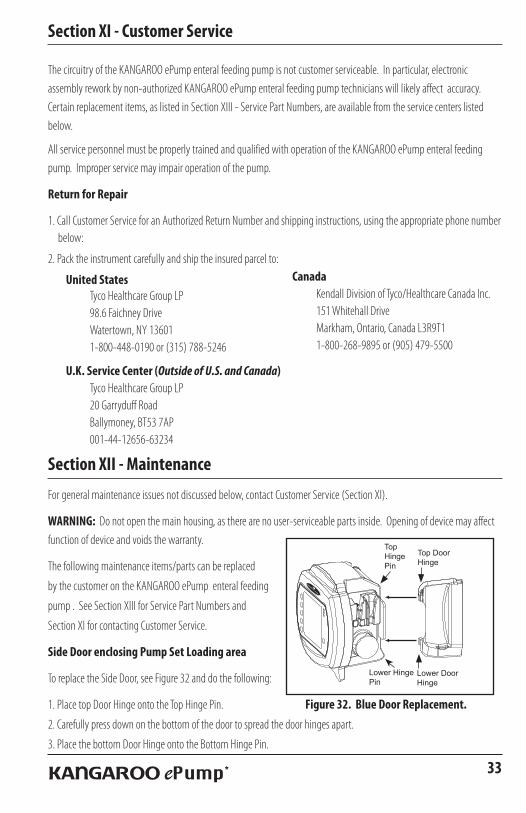
Side Door enclosing Pump Set Loading area
To replace the Side Door, see Figure 32 and do the following:
1. Place top Door Hinge onto the Top Hinge Pin.
2. Carefully press down on the bottom of the door to spread the door hinges apart.
3. Place the bottom Door Hinge onto the Bottom Hinge Pin.
Canada Kendall Division of Tyco/Healthcare Canada Inc. 151 Whitehall Drive Markham, Ontario, Canada L3R9T1 1-800-268-9895 or (905) 479-5500
33KANGAROO ePump *
TopHingePin
Top Door Hinge
Lower Door Hinge
Lower HingePin
Figure 32. Blue Door Replacement.

Battery Pack
See Section VIII for full instructions on replacing Battery Pack.
Battery Door
To replace Battery Door, see Figure 33 and do the following:
1. Align the Battery Door Hinges with the long hinge pins.
2. Snap the hinges onto the hinge pins.
3. Screw down the door to hold in place.
Power Cord
See Section IV for initial setup, including Power Cord attachment.
Pole Clamp
See Section IV for initial setup, including attachment of the Pole Clamp to the pump.
Section XIII - Service Part Numbers
To place an order for parts, or if technical assistance is required, call customer service.
The KANGAROO ePump enteral feeding pump contains a limited number of serviceable parts. User maintenance is to be
performed only by appropriately qualified technical personnel.
Visit our web site at: www.TycoHealthcare.com
(1) KANGAROO ePump . . . . . . . . . . . . . . . . .382400 (2) Main Door (Blue transparent door). .F31877WT (3) Battery Pack . . . . . . . . . . . . . . . . . . .F010484WT (4) Battery Door (with Screw). . . . . . . . . F31878WT Power Cord (with A/C Adapter). . . . . . .F010486WT (5) Pole Clamp . . . . . . . . . . . . . . . . . . . . . A11164WT Re-Certification Pump Set . . . . . . . . . . . . . . 776150
Section XIV - Warranty
LIMITED WARRANTY: Kendall, a Tyco Healthcare Group LP company, warrants to the original purchaser (“Customer”)
that this product will be free of defects in materials and workmanship, under normal use, for one (1) year from the
date of original purchase from Kendall or its authorized distributor. If this product does not operate as warranted above
during the applicable warranty period, Kendall may, at its option and expense, replace the defective part or product with
a comparable part or product, repair the defective part or product, or, if neither replacement nor repair is reasonably
available, refund to Customer the purchase price for the defective part or product. Dated proof of original purchase will
be required. Kendall does not assume any liability for loss arising from unauthorized repair, misuse, neglect, or accident.
Figure 33. Battery Door Replacement.
34 KANGAROO ePump *
1
3
2
Figure 34. User Serviceable Parts.
4
5
35KANGAROO ePump *
Section XV - Electromagnetic Conformity Declaration
The KANGAROO ePump enteral feeding pump has been built and tested according to UL60601-1, E181931 CSA-C22.2 No.601.1-M90, and EN60601-1-2 Standards.
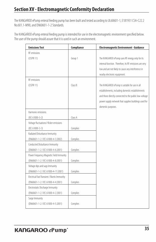
The KANGAROO ePump enteral feeding pump is intended for use in the electromagnetic environment specified below. The user of the pump should assure that it is used in such an environment.
Emissions Test Compliance Electromagnetic Environment - Guidance
RF emissions
(CISPR 11) Group 1 The KANGAROO ePump uses RF energy only for its
internal function. Therefore, its RF emissions are very
low and are not likely to cause any interference in
nearby electronic equipment.
RF emissions
(CISPR 11) Class B The KANGAROO ePump is suitable for use in all
establishments, including domestic establishments
and those directly connected to the public low-voltage
power supply network that supplies buildings used for
domestic purposes.
Harmonic emissions
(IEC 61000-3-2) Class A
Voltage fluctuations/ flicker emissions
(IEC 61000-3-3) Complies
Radiated Disturbance Immunity
(EN60601-1-2 / IEC 61000-4-3:2002) Complies
Conducted Disturbance Immunity
(EN60601-1-2 / IEC 61000-4-6:2001) Complies
Power Frequency Magnetic Field Immunity
(EN60601-1-2 / IEC 61000-4-8:2001) Complies
Voltage dips and sags Immunity
(EN60601-1-2 / IEC 61000-4-11:2001) Complies
Electrical Fast Transient / Bursts Immunity
(EN60601-1-2 / IEC 61000-4-4:2001) Complies
Electrostatic Discharge Immunity
(EN60601-1-2 / IEC 61000-4-2:2001) Complies
Surge Immunity
(EN60601-1-2 / IEC 61000-4-5:2001) Complies

Patents pending.
*KANGAROO ePump is a trademark of Sherwood Services AG†SPRAY-NINE is a trademark Spray-Nine Corporation
PHISOPHEX is a trademark of Smith Kline Beecham Corp.HIBICLENS is a trademark of Tubifoam Ltd. VESTA-SYDE is a trademark of Steris, Inc.
TYCO HEALTHCARE GROUP LP ■ MANSFIELD, MA 02048 ■ MADE IN U.S.A. ■ © 2004 TYCO HEALTHCARE GROUP LP. ALL RIGHTS RESERVED. 040415 ■ IN U.S. 1-800-962-9888 ■ www.TycoHealthcare.com ■ EC REP TYCO HEALTHCARE U.K. LTD, GOSPORT, P013OAS, U.K. ■ SWISS DISTRIBUTOR: TYCO HEALTHCARE SWITZERLAND LTD, ROOSTRASSE 53, POSTFACH CH-8832, WOLLERAU SWITZERLAND
182321


