TX5 FM Broadcast Transmitter - Radikal · PDF fileBW Broadcast technical manual Page 4...
50
TX5 FM Broadcast Transmitter No part of this manual may be re-produced in any form without prior written permission from BW Broadcast. The information and specifications contained in this document is subject to change at any time without notice. Copyright 2010 BW Broadcast www.bwbroadcast.com Technical Manual
-
Upload
truonglien -
Category
Documents
-
view
282 -
download
8
Transcript of TX5 FM Broadcast Transmitter - Radikal · PDF fileBW Broadcast technical manual Page 4...

TX5 FM Broadcast Transmitter
No part of this manual may be re-produced in any form without prior written permission from BW Broadcast. The information and specifications contained in this document is subject to change at any time without notice.
Copyright 2010 BW Broadcast
www.bwbroadcast.com
Technical Manual

WARNING
This transmitter should never be operated without a suitable antenna or test dum-my load! Failure to observe this requirement may result in damage to the transmit-ter that is not covered by the warranty.
IMPORTANT
This transmitter has been shipped with the internal stereo generator enabled. The internal jumper J1 (MPX loop-through) is set to ON.
If you intend to connect a MPX signal to the MPX input BNC connector you will need to move J1 (MPX loop-through) to the OFF position.
Examples of configurations requiring setting J1 to OFF include:
● Routing the internal MPX signal through an external RDS encoder. ● Connecting an external audio processor or stereo generator to the
transmitter. ● Connecting a re-broadcast or STL receiver to the transmitter.
Consult the manual for further information on the transmitter’s jumpers and con-nections.

BW Broadcast technical manual Page 3
CONTENTS
1. Introduction 1.1 TX FM Transmitter 1.2 Warranty 1.3 Safety 1.4 Quick setups 1.5 Front And Rear Panels 1.6 Control And Monitor LCD
2. Installation And Setup 2.1 Frequency Setup 2.2 R.F. Power Setup 2.3 Alarms 2.4 RS232 Control & Monitoring 2.41 Windows remote control application 2.42 Terminal control of the transmitter 2.5 Modes Of Operation 2.51 A guide to the jumpers 2.52 Multiplex / Broadband Input
2.53 Stereo With Limiters 2.54 Stereo With Limiters Disabled 2.55 Mono From Two Channels 2.56 Mono From One Channel 2.6 Other Setup Considerations
3. Technical data 3.1 Specifications 3.2 Circuit Description 3.21 Combo board 3.22 LCD control board 3.23 Power amplifier board 3.3 Block Diagram 3.4 Internal Wiring / Case Overview 3.5 Schematics 3.51 Combo section 3.511 Limiter section 3.512 Coder section 3.513 Exciter section 3.52 LCD control section 3.53 Power amplifier section 3.6 Parts List 3.61 Combo board parts list 3.62 LCD control board parts list 3.63 Power amplifier board parts list

BW Broadcast technical manual Page 4
Introduction
1.1 TX5 FM TRANSMITTER
The BW Broadcast TX5 is a high specification FM broadcast transmitter. Its broadband “no-tune” design allows 87.5-108 MHz operation from internal direct reading rotary switches or the front panel LCD frequency control sys-tem if enabled. Digital PWM techniques provide an easily adjustable and accurate automatic level controlled R.F. output of the MOS-FET power amplifier stage.
RF, audio and other parameters are shown on the LCD graphics display. This display offers a very easy method of transmitter parameter monitoring and a new level of ease for setup and installation, with metering accuracy normally only found on expensive test equipment. Local and remote personal computer control and metering are achievable via RS232 interface and there's an alarm I/O as well.
The FM modulator section employs a dual speed “virtual VFO” system for extremely low audio distortion and excellent stereo performance.
A built in high specification stereo encoder provides crystal clear stereo sound and combined with the internal lim-iter a fully compliant “plug and play” all in one low power broadcast transmitter.
For future compatibility all settings are switchable with on board jumpers. The stereo and/or limiter settings can be switched in and out to suit the requirements of any external broadcast equipment you may have now and in the future.
The lightweight universal mains input design ensures a high reliability efficient design compatabile with any mains system in the world.

BW Broadcast Technical Manual Page 5
Introduction
1.2 WARRANTYBW Broadcast warrants the mechanical and electronic components of this product to be free of defects in material and workmanship for a period of two (2) years from the original date of purchase, in accordance with the warranty regulations described below. If the product shows any defects within the specified warranty period that are not due to normal wear and tear and/or improper handling by the user, BW Broadcast shall, at its sole discretion, either repair or replace the product. If the unit has a manufacturers fault within twenty eight (28) days then BW Broadcast will pay the freight at their discretion. If the warranty claim proves to be justified, the product will be returned to the user freight prepaid. Warranty claims other than those indicated above are expressly excluded.
Return authorisation numberTo obtain warranty service, the buyer (or his authorized dealer) must call BW Broadcast during normal business hours BEFORE returning the product. All inquiries must be accompanied by a description of the problem. BW Broadcast will then issue a return authorization number.Subsequently, the product must be returned in its original shipping carton, together with the return authorization number to the address indicated by BW Broadcast. Shipments without freight prepaid will not be accepted.
Warranty regulationsWarranty services will be furnished only if the product is accompanied by a copy of the original retail dealer’s invoice. Any product deemed eligible for repair or replacement by BW Broadcast under the terms of this warranty will be repaired or replaced within 30 days of receipt of the product at BW Broadcast.
If the product needs to be modified or adapted in order to comply with applicable technical or safety standards on a national or local level, in any country which is not the country for which the product was originally developed and manufactured, this modification/adaptation shall not be considered a defect in materials or workmanship. The warranty does not cover any such modification/adaptation, irrespective of whether it was carried out properly or not. Under the terms of this warranty, BW Broadcast shall not be held responsible for any cost resulting from such a modification/adaptation.
Free inspections and maintenance/repair work are expressly excluded from this warranty, in particular, if caused by improper handling of the product by the user. This also applies to defects caused by normal wear and tear, in particular, of faders, potentiometers, keys/buttons and similar parts.
Damages/defects caused by the following conditions are not covered by this warranty:Misuse, neglect or failure to operate the unit in compliance with the instructions given in BW Broadcast user or service manuals. Connection or operation of the unit in any way that does not comply with the technical or safety regulations applicable in the country where the product is used. Damages/defects caused by force majeure or any other condition that is beyond the control of BW Broadcast. Any repair or opening of the unit carried out by unauthorized personnel (user included) will void the warranty.
If an inspection of the product by BW Broadcast shows that the defect in question is not covered by the warranty, the inspection costs are payable by the customer.
Products which do not meet the terms of this warranty will be repaired exclusively at the buyer’s expense. BW Broadcast will inform the buyer of any such circumstance. If the buyer fails to submit a written repair order within 6 weeks after notification, BW Broadcast will return the unit C.O.D. with a separate invoice for freight and packing. Such costs will also be invoiced separately when the buyer has sent in a written repair order.
Warranty transferabilityThis warranty is extended exclusively to the original buyer (customer of retail dealer) and is not transferable to anyone who may subsequently purchase this product. No other person (retail dealer, etc.) shall be entitled to give any warranty promise on behalf of BW Broadcast.
Claims for damagesFailure of BW Broadcast to provide proper warranty service shall not entitle the buyer to claim (consequential) damages. In no event shall the liability of BW Broadcast exceed the invoiced value of the product.
Other warranty rights and national lawThis warranty does not exclude or limit the buyer’s statutory rights provided by national law, in particular, any such rights against the seller that arise from a legally effective purchase contract. The warranty regulations mentioned herein are applicable unless they constitute an infringement of national warranty law.

BW Broadcast technical manual Page 6
Introduction
1.3 SAFETYMAINS VOLTAGEThis equipment operates from an AC power source of between 90 and 265 volts. There are hazardous voltages present internally. PLEASE OBSERVE CAUTION WITH THE COVER REMOVED.
SWITCHED MODE POWER SUPPLY HAZARDPlease note that the power supply units in this equipment is of the switched mode variety and have lethal voltages present internally. The switched mode supplies are universal input fully approved type. They are non serviceable modules and should be fully replaced should they fail.
FUSESOnly use fuses with the specified voltage and current ratings as stated on the back panel. Failure to do so may increase the risk of equipment failure, shock and fire hazard.
R.F.The N type R.F. power output socket contains R.F. voltages which may burn or present a shock. Please make sure that the equipment is connected to an adequately rated load or antenna system while in opera-tion.
TOXIC HAZARDThis equipment includes R.F. components that may contain Beryllium oxide which is a highly toxic sub-stance that could be hazardous to health if inhaled or ingested. Care should be taken when replacing or discarding such devices. Seek expert advice from the manufacturer should you physically damage a device that contains Berillyium Oxide. The main R.F. output power transistor contains Beryllium oxide.
OTHER SAFETY CONSIDERATIONSDo not operate this equipment in the presence of flammable gases, fumes or liquids
Do not expose this equipment to rain or water.
CE CONFORMANCEThis device complies with the requirements of the 1995/5/EC Radio and Telecommuni-cations Terminal Equipment (R&TTE). The equipment will meet or exceed the following standards: EN 60215:1996 (Safety Requirements for Radio Transmitting Equipment), EN 301 489-11 (ERM/EMC for Radio Equipment, Part 11 Specific Conditions for FM Transmitters), EN 302 018-2 ERM (Transmitting Equipment for FM Radio Broadcasting service)
The operating frequencies of this transmitter may not be harmonised in the intended countries of use. The user must obtain a license before using the product in the intend-ed country of use. Ensure respective country licensing requirements are complied with. Limitations of use can apply in respect of operating frequency, transmitter power and/or channel spacing.
WEEE COMPLIANCEBW Broadcast Ltd is registered with Northern Compliance PCS number WEE/P3438PR/SCH and has been issued with WEE/FA0268RX as its unique producer ID by the appro-priate environment agency. BW Broadcast Ltd full comply with it explicit responsibilities, subject to WEEE Collections Policy outlined in their General Terms and conditions of Sale, when it sells Electrical and Electronic Equipment (EEE) to B2B customers in the UK and EU.
This appliance has been designed and manufactured with high quality materials and components that can be recycled and reused. Electronic appliances are liable to contain parts that are necessary in order for the system to work properly but which can become a health and environmental hazard if they are not handled and disposed of in the proper way. Consequently, please do not throw your inoperative appliance with the household waste. Having purchased this appliance it is your responsibility to dispose of this equipment appropriately.

BW Broadcast technical manual Page 7
Introduction
1.4 Quick set-up guideUsing a transmitter stand-alone (without RDS encoder)
This set-up uses the built-in audio limiter and stereo generator. The transmitter as shipped from factory is already configured for this set-up, so there are no internal changes to be made.
1. Place a transmitter in a well ventilated space. If it's rack-mounted, leave at least 1U free above and be-low it for adequate cooling.
2. Connect the antenna to the RF output N-connector on the back of the transmitter.
3. Connect the left and right program audio signals to the XLR input connectors on the back of the transmit-ter.
4. Plug in the power cord to the transmitter.
5. Once the transmitter is operating, set the correct carrier frequency from the front panel (this can also be locked and set internally).
6. Adjust the desired power output level using front panel. Check reflected power is OK.
7. Check the gain reduction of the built-in limiter - it should be doing a couple of dB with normal program level. If necessary adjust the audio input level trimmers on the back of the transmitter.
That finishes the set-up. A much more detailed explanation is available in the appropriate sections of this manual as well as additional options. You should read through it!

BW Broadcast technical manual Page 8
Introduction
1.4 Quick set-up guideUsing a transmitter stand-alone with RDS encoder
This set-up uses the built-in audio limiter and stereo generator.
1. Remove the screws that hold the lid of the transmitter and remove the lid.
2. Locate the main board on the right side of the transmitter. Locate jumper J1 right behind the BNC con-nectors. Move it to down position (Loop-through off).
3. Reassemble the lid back on.
4. Place a transmitter in a well ventilated space. If it's rack-mounted, leave at least 1U free above and be-low it for adequate cooling.
5. Connect the antenna to the RF output N-connector on the back of the transmitter.
6. Connect the left and right program audio signals to the XLR input con-nectors on the back of the transmitter.
7. Connect the Baseband/MPX output on the back of the transmitter to the MPX input of the RDS encoder.
8. Connect the MPX output of the RDS encoder to the MPX input on the back of the transmitter.
9. Plug in the power cord to the transmitter.
10. Once the transmitter is operating, set the correct carrier frequency from the front panel (this can also be locked and set internally).
11. Adjust the desired power output level using front panel. Check reflected power is OK.
12. Check the gain reduction of the built-in limiter - it should be doing a couple of dB with normal program level. If necessary adjust the audio input level trimmers on the back of the transmitter.
13. Check the documentation that came with your RDS encoder on how to set/check the proper RDS injec-tion level.
That finishes the set-up. A much more detailed explanation is available in the appropriate sections of this manual as well as additional options. You should read through it!
Audio processor
INOUTMPX
BW BroadcastTransmitter
RF OUT IN OUTMPX
Audio processor
INOUTMPX
BW BroadcastTransmitter
RF OUT IN OUTMPX
RD
S encoder
INO
UT
MP
X
Audio processor
BW BroadcastTransmitter
RF OUT IN OUTMPX
RD
S encoderIN
OU
TR
DSPILO
T
OUTINSCA PILOT
OUTMPX
RDS encoderINOUT
MPX
BW BroadcastTransmitter
RF OUT IN OUTMPX
MPX connections

BW Broadcast technical manual Page 9
Introduction
1.4 Quick set-up guide
Using a transmitter with external audio processor/stereo generator but without RDS encoder
1. Remove the screws that hold the lid of the transmitter and remove the lid.
2. Locate the main board on the right side of the transmitter. Locate jumper J1 right behind the BNC con-nectors. Move it to down position (Loop-through off).
3. Reassemble the lid back on.
4. Place a transmitter in a well ventilated space. If it's rack-mounted, leave at least 1U free above and be-low it for adequate cooling.
5. Connect the antenna to the RF output N-connector on the back of the transmitter.
6. Connect the MPX output of your audio processor (or stereo generator) to the MPX input on the back of the transmitter.
7. Plug in the power cord to the transmitter.
8. Once the transmitter is operating, set the correct carrier frequency from the front panel (this can also be locked and set internally).
9. Adjust the desired power output level using front panel. Check reflect-ed power is OK.
10. Check the modulation level - if the modulation level is low, adjust the MPX output level on your audio processor (or stereo generator) and/or the MPX input level on the back of the transmitter. The maximum modulation should not exceed 75kHz.
11. Check the documentation that came with your audio processor on how to set/check the proper pilot injection level.
That finishes the set-up. A much more detailed explanation is available in the appropriate sections of this manual as well as additional options. You should read through it!
Audio processor
INOUTMPX
BW BroadcastTransmitter
RF OUT IN OUTMPX
Audio processor
INOUTMPX
BW BroadcastTransmitter
RF OUT IN OUTMPX
RD
S encoder
INO
UT
MP
X
Audio processor
BW BroadcastTransmitter
RF OUT IN OUTMPX
RD
S encoderIN
OU
TR
DSPILO
T
OUTINSCA PILOT
OUTMPX
RDS encoderINOUT
MPX
BW BroadcastTransmitter
RF OUT IN OUTMPX
MPX connections

BW Broadcast technical manual Page 10
Introduction
1.4 Quick set-up guideUsing a transmitter with external audio processor/stereo generator
and with RDS encoder (in-line connection)
1. Remove the screws that hold the lid of the transmitter and remove the lid.
2. Locate the main board on the right side of the transmitter. Locate jumper J1 right behind the BNC con-nectors. Move it to down position (Loop-through off).
3. Reassemble the lid back on.
4. Place a transmitter in a well ventilated space. If it's rack-mounted, leave at least 1U free above and below it for adequate cooling.
5. Connect the antenna to the RF output N-connector on the back of the transmitter.
6. Connect the MPX output of your audio processor (or stereo gen-erator) to the MPX input of your RDS encoder.
7. Connect the MPX output of your RDS encoder to the MPX input on the back of the transmitter.
8. Plug in the power cord to the transmitter.
9. Once the transmitter is operating, set the correct carrier frequency from the front panel (this can also be locked and set internally).
10. Adjust the desired power output level using front panel. Check reflected power is OK.
11. Check the modulation level - if the modulation level is low, adjust the MPX output level on your audio processor (or stereo generator), RDS encoder and/or the MPX input level on the back of the transmitter. The maximum modulation should not exceed 75kHz.
12. Check the documentation that came with your audio processor on how to set/check the proper pilot injection level.
13. Check the documentation that came with your RDS encoder on how to set/check the proper RDS injec-tion level.
That finishes the set-up. A much more detailed explanation is available in the appropriate sections of this manual as well as additional options. You should read through it!
Audio processor
INOUTMPX
BW BroadcastTransmitter
RF OUT IN OUTMPX
Audio processor
INOUTMPX
BW BroadcastTransmitter
RF OUT IN OUTMPX
RD
S encoder
INO
UT
MP
X
Audio processor
BW BroadcastTransmitter
RF OUT IN OUTMPX
RD
S encoderIN
OU
TR
DSPILO
T
OUTINSCA PILOT
OUTMPX
RDS encoderINOUT
MPX
BW BroadcastTransmitter
RF OUT IN OUTMPX
MPX connections

BW Broadcast technical manual Page 11
Introduction
1.4 Quick set-up guideUsing a transmitter with external audio processor/stereo generator
and with RDS encoder (sidechain connection)
This is the best connection in terms of pilot and RDS subcarrier phase syncronization and MPX spectrum cleanli-ness.
1. Remove the screws that hold the lid of the transmitter and remove the lid.
2. Locate the main board on the right side of the transmitter. Locate jumper J1 right behind the BNC con-nectors. Move it to down position (Loop-through off).
3. Reassemble the lid back on.
4. Place a transmitter in a well ventilated space. If it's rack-mounted, leave at least 1U free above and below it for adequate cooling.
5. Connect the antenna to the RF output N-connector on the back of the transmitter.
6. Connect the MPX output of your audio processor (or stereo generator) to the MPX input on the back of the transmitter.
7. Connect the Pilot output of your audio processor (or stereo generator) to the Reference input on your RDS encoder.
8. Connect the MPX output of your RDS encoder to the SCA input on your audio processor.
9. Plug in the power cord to the transmitter.
10. Once the transmitter is operating, set the correct carrier frequency from the front panel (this can also be locked and set internally).
11. Adjust the desired power output level using front panel. Check reflected power is OK.
12. Check the modulation level - if the modulation level is low, adjust the MPX output level on your audio processor (or stereo generator) and/or the MPX input level on the back of the transmitter. The maximum modulation should not exceed 75kHz.
13. Check the documentation that came with your audio processor on how to set/check the proper pilot injection level.
14. Check the documentation that came with your RDS encoder on how to set/check the proper RDS injec-tion level.
That finishes the set-up. A much more detailed explanation is available in the appropriate sections of this manual as well as additional options. You should read through it!
Audio processor
INOUTMPX
BW BroadcastTransmitter
RF OUT IN OUTMPX
Audio processor
INOUTMPX
BW BroadcastTransmitter
RF OUT IN OUTMPX
RD
S encoder
INO
UT
MP
X
Audio processor
BW BroadcastTransmitter
RF OUT IN OUTMPX
RD
S encoderIN
OU
TR
DSPILO
T
OUTINSCA PILOT
OUTMPX
RDS encoderINOUT
MPX
BW BroadcastTransmitter
RF OUT IN OUTMPX
MPX connections

BW Broadcast technical manual Page 12
Introduction
1.5 FRONT AND REAR PANELS
1.
Left
audi
o in
put
2.
Left
Inpu
t gai
n3.
R
ight
inpu
t gai
n4.
R
ight
aud
io in
put
5.
MP
X o
utpu
t6.
M
PX
leve
l con
trol
7.
MP
X In
put
8.
I/O +
Ala
rms
9.
RS
232
10.
R.F
. out
put
11.
Pow
er s
ocke
t12
. C
hass
is g
roun
d po
st13
. R
F m
onito
r out
put -
50dB
c (n
ot s
uita
ble
for
harm
onic
mea
sure
men
ts)
I/O -
Ala
rms
D-ty
pe c
onne
ctor
pin
out:
Pin
1
MO
D fa
ilure
ala
rm (T
TLP
in 2
P
LL fa
ilure
ala
rm (T
TL)
Pin
3
RF
failu
re a
larm
(TTL
)P
in 4
R
F M
ute
Pin
5
+18
V D
C 2
00m
AP
in 6
M
OD
failu
re a
larm
(OC
)P
in 7
P
LL fa
ilure
ala
rm (O
C)
Pin
8
RF
failu
re a
larm
(OC
)P
in 9
G
ND
XLR
Aud
io in
put c
onne
ctor
s
FAU
LT
VSW
RTE
MP
TX
5
1718
121
23
45
67
8, 9
1011
13, 1
415
16
14.
Mod
ulat
ion
mon
itor o
utpu
t (bu
ffere
d m
ultip
lex,
no
min
ally
3V
pea
k-to
-pea
k fo
r 75k
Hz)
15.
VS
WR
and
tem
pera
ture
faul
t LE
Ds
16.
Max
imum
forw
ard
pow
er a
djus
t17
. LC
D d
ispl
ay18
. U
p / D
own
frequ
ency
but
tons
PIN
1 G
ND
PI
N2
Hot
(+)
PIN
3 C
old
(-)
FAU
LT
VSW
RTE
MP
TX
30
0
12
3
FAU
LT
VSW
RTE
MP
TX
30
0
5 4
3
2
1
9 8
7
6

BW Broadcast technical manual Page 13
Introduction
1.6 CONTROL AND MONITOR LCD
The front panel LCD graphics display has seven screens (shown below). These allow monitoring of the transmit-ter’s R.F, audio and other parameters and the adjustment (if internally allowed) of the transmitter’s frequency. You can move through the screens by pressing the NEXT button, which will display them in the following order.
Main parameter screen.
This shows together the three most important transmitter parameters. Frequency, R.F. output power and the peak deviation.
Frequency display and control
This screen will display the frequency and PLL locked condi-tion. The up and down buttons will allow 100 kHz frequency steps from 87.5 to 108Mhz if the internal switches are set to 4440. If the frequency is set internally with the rotary switches then the up / down buttons will give a ‘not allowed’ message
Peak deviation
This display indicates the peak and average deviation. Peak deviation is shown both numerically and as a moving single pixel wide bar. Average deviation is shown with the solid black bar. Over-deviation will display an exclamation ( ! )
Gain reduction
This display indicates the amount of gain reduction of the internal audio limiter. The range is 0 to 24 decibels of gain reduction.
Power supply
Power amplifier voltage is shown together with the transmit-ters secondary supply that feeds the exciter section. The power amplifier voltage will vary depending on set output power and the presence of any fault conditions which also cut the voltage back and with it the R.F. output.

BW Broadcast technical manual Page 14
Installation and setup
2.1 FREQUENCY SETUPThe Frequency can be set on the transmitter in one of two ways:
1. From internal direct reading decimal switches on the main board 2. From the front panel LCD display and front panel buttons.
Many radio regulatory bodies stipulate that the transmitters parameters including the frequency must not be easily changed from the front panel. To meet this requirement you will need to set the frequency internally with the dial switches.The switches have a silkscreen diagram next to them on the board (see diagram below) clearly indicating what each switch represents.The top dial switch represents the value selected x 10 Mhz with the exception of ‘0’ which represents 10 so when selected would equal 100 Mhz.The second dial switch represents the value selected x 1 Mhz. The third dial switch represent the value selected x .1 Mhz (100 kHz)The bottom switch represents the value selected x .0125 Mhz (12.5 kHz)
For example:
FREQ SWITCHES (MHz) X10 X1 X.1 X.0125 87.90 ‘8’ ‘7’ ‘9’ ‘0’ 98.75 ‘9’ ‘8’ ‘7’ ‘4’ 100.00 ‘0’ ‘0’ ‘0’ ‘0’ 104.225 ‘0’ ‘4’ ‘2’ ‘2’ 108.00 ‘0’ ‘8’ ‘0’ ‘0’
As you can see, the switches directly read the frequency with the exception of frequencies above 100 Mhz, where the top switch being set at ‘0’ represents ‘10’. The X0.125 ‘offset’ switch is only used when you want to pro-vide a shift to the carrier of between 12.5 kHz and 112.5 kHz. Note that setting the switch on 8 or 9 will have the same effect as setting the previous switch (100 kHz) 1 position higher, as 8 represents 100 kHz on the 12.5 kHz switch. 8 x 0.125MHz = 0.1MHz = 100kHz
The LCD display on the front panel will display the frequency that you have set on the internal switches. If you try to adjust the frequency with the front panel up / down buttons you will get a ‘ NOT ALLOWED ‘ message appear-ing on the LCD display. This protects against unauthorized front panel frequency changes when the frequency has been set internally with the dial switches.
The TX will load the switch values at power up. You will need to remove the mains power to the transmitter and then reapply it if you want to change the frequency by using the direct reading switches
LCD front panel frequency selection.
If you want to control the frequency from the front panel LCD con-trol system you will need to set the internal switches to 4440. The transmitter will pass frequency control to the LCD control system and the frequency can be moved up and down by pressing the NEXT button until the frequency menu is displayed. The other two buttons control the UP and DOWN frequency selection. PLL lock status is also displayed on this screen.
The LCD readout will only display frequencies in 100Khz steps. Any frequency offsets derived from the internal 12.5kHz offset switch will not show on the LCD. Consult a frequency counter if using offsets.
Note that some pcb’s have “set to 4444 for front panel LCD control”. This is an error that will cause a +50kHz offset to the frequency set on the LCD screen. Please set to 4440 unless you specifically want the offset.
Frequency selection switches on main board
Fine frequency control. Do not adjust unless you know what you are doing. Consult advanced setup section of manual for more information.

BW Broadcast technical manual Page 15
Installation and setup
2.2 R.F. POWER SETUPThe R.F. power output from the transmitter can be controlled by an analogue potentiometer (POT) or from the front panel LCD screen or a combination of both.
ANALOGUE POWER CONTROL
If the frequency is set internally with the dial switches you will not be able to adjust the power from the LCD screen. This is to comply with regulatory body’s that stipulate that the transmitter is not to have it’s parameters adjustable from the front panel. In this case you must use the maximum power set control to set the transmitters power. This control will give the full power range adjustment.
If the transmitter has been internally set to 4440 with the dial switches then you can also control the power from the LCD screen’s R.F. power menu’s up and down buttons. A “not allowed” message will be displayed to the user if the dial switches are not set to 4440
RS232 power control will over-ride the power control restrictions caused by having the frequency set internally (not set to 4440).
DIGITAL POWER CONTROL
When the power is to be controlled from the front panel the max power set POT takes on a new role of setting the maximum power of the transmitter. If you want the LCD screen to have full power range control of the transmitter you will need to ensure that the max power set control is at maximum power. Otherwise your control range may be limited. This feature enables you to limit the transmitters maximum power to a fixed level but to still allow the LCD screen to provide adjustment of the R.F. power down from that maximum power set point. This can be desir-able in transmitter hire situations where you wish to govern the maximum output to a fixed level but to allow the customer (hirer of the transmitter) to run the power of the transmitter at a lower level if they so decide.
The maximum power set is positioned to the lower left of the LCD screen on some models, other models may not have the hole in the front panel and you will need to remove the lid of the transmitter to access the adjust-ment which will be in the same position but on the other side of the PCB. You will need a small ‘tweaker style’ flat-head screwdriver to adjust the pot. This control is quite delicate so try to not be too heavy handed in it’s adjust-ment.
Please note that the VSWR and temperature protection circuitry will turn back the R.F. power if a fault con-dition exists. Make sure that you have a good VSWR (low reverse power reading) before setting the R.F. power as the removal of a fault condition may cause the R.F. power to increase.
RF POWER MUTE (analogue)
There is a pin (2) on the back panel I/O D-type that can be pulled low to mute the trans-mitters RF power.
RF POWER MUTE (digital/RS232)
The transmitters RF power output can be muted via the RS232 control system. Terminal software can mute/unmute the RF power with the ‘o’ and ‘f’ commands respectively.
The windows application has a button that can toggle the RF output of the trans-mitter.
Please consult the RS232 section of this manual for more information on controlling the transmitter remotely.
FUSE
1 2 3 4 5 6 7 8 9 11 131210
TX150/300�FM TRANSMITTER
FUSE
1 2 3 4 5 6 7 8 9 11 131210
TX25/50�FM TRANSMITTER
FUSE
1 2 3 4 5 6 7 8 9 11 131210
TX1�FM TRANSMITTER
B W - T X 6 0 0
FAULT
VSWR TEMP
1 2 3 4 5
6 7 8 9

BW Broadcast technical manual Page 16
Installation and setup
2.3 ALARMSThe transmitter has three alarms that can alert the broadcaster if one of the following fails:
R.F. POWER, PLL LOCK, MODULATION
The alarms when set are available on the back panel 9-pin D-type. Each alarm has an open collector (OC) and a TTL level contact on the D-type. The alarm induced active open collectors can pull down any external signals and the TTL outputs will provide a 5 Volt indication. The alarm is also visible if any RS232 monitoring (through Windows Remote Control application or terminal software) is employed.
For the alarms to function correctly the transmitter must be left on the default menu screen. This is the screen that displays frequency, R.F. power and peak deviation. To ensure that the alarm system functions correctly the trans-mitter will return to the default menu screen if the LCD is left on another menu screen for more than 5 minutes.
R.F. POWER.
The R.F. power alarm will be set if the R.F. power falls below a threshold level during normal operation. This threshold is set below the normal operating lowest wattage available from the transmitter. If you require a different setting for the alarm, contact our tech dept. The alarm will only be set if the fault condi-tion exists for sixty seconds or more. You will need to reset the transmitter to clear the alarm/s or you can do it via RS232 connection.
PLL LOCK.
The PLL lock alarm will be set if the transmitters falls out of frequency lock during normal operation. The alarm will only be set if the fault condition exists for sixty seconds or more. You will need to reset the trans-mitter to clear the alarm/s or you can do it via RS232 connection.
MODULATION FAILURE.
The Modulation failure alarm will be set if during normal operation the peak deviation of the transmitter drops and remains below 16 kHz. The 16 kHz alarm level allows the alarm to be set if the audio feed to the transmitter fails even if the stereo pilot internal to the transmitter is still modulating the transmitter. The alarm will only be set if the fault condition exists for sixty seconds or more. You will need to reset the trans-mitter to clear the alarm/s or you can do it via RS232 connection. MORE INFO ON ALARMS
The three alarms are available on the back panel D-type connector. The pin-outs are shown on the rear panel diagram. The three alarms are available as TTL level and as open collector outputs. The TTL level outputs are active high in the event of an alarm. The open collector outputs are ON in the event of an alarm and will pull down any external levels. The open collectors can sink 100 mA MAX with an absolute maxi-mum switched voltage of 25 volts.
The D-type connector can also supply 18 volts at 200 mA that can be used for pull-ups on the open collec-tor alarm outputs and for your own external switching circuitry.
The RS232 interface provides the ability to reset the alarms either through Windows Remote Control appli-cation or terminal software. More info is found in the following pages of the manual.
BW Broadcast can also customise the alarm / fault software to meet the requirements of major broadcast-ers and networks or supply N+1 solutions. More information on this and other custom features can be obtained from our technical department.

BW Broadcast technical manual Page 17
Installation and setup
2.4 RS232 CONTROL AND MONITORING
The TX range of transmitters can be monitored or controlled from a personal computer either locally or remotely. The Transmitters can “chat” either by a windows application or via a standard serial terminal program. The win-dows application is the more versatile option and is to be preferred but the ability to use a terminal program can prove useful in the absence of the windows application or a computer that runs windows.
2.41 Windows remote control applicationThe latest version of Windows remote control application can be downloaded from:http://www.bwbroadcast.com
Installation
After downloading just click on the .msi file to run the set up program. The set up will place icons in both the Windows start menu and on your desktop. Simply run the program by clicking on icon from either location.
Running the application
When started the application will resemble the picture to the right.
The application can connect to any COM port currently available on your com-puter that is running the application. Connect a serial cable between the RS232 connector on the rear of the transmitter and one of your computers COM ports. If you are using a codec or other STL device then you may be able to connect that device in line to act as part of the serial link.
Selected the COM port you want to use and then click the Connect button.
If the application is able to connect to the transmitter then you will be presented with a screen similar to the one above. Once connected you should be able to monitor all the parameters of the transmitter as well as being able to mute the R.F., change the frequency, change the R.F. power and reset any alarm flags that have been set.
2.42 Terminal control of the transmitter
Installation
Please see the instructions for your terminal software package to find out how to connect to a remote serial device. The transmitter is internally set to communicate at 9600 bps, no parity with 1 stop bit and hardware flow control. This is commonly known as 9600 8N1. If your using Windows then you can use the pre-bundled terminal program “Hyper-terminal”. This is located in the Programs -> Accessories -> Communications folder accessible
Remote Control Applictiona startup screen
Remote Control Application

BW Broadcast technical manual Page 18
Installation and setup
from the Start menu. Select direct to COM port x where x is the com port that the transmitter is connected to. You will be presented with a dialog box like the one shown to the right. Select 9600, 8, none ,1 with hardware flow control and then click OK.
If you are using another terminal program then you may need to consult the documentation for that software, but it should be pretty much straight for-ward.
Operation
The transmitter will respond to certain key presses and each one has a certain function. See the list below for details of what key to press for each function.
The most important key press is the ‘Enter’ key. This will need to be pushed as soon as you connect to the transmitter so you can get the transmitter to refresh your terminal window with the transmitters sta-tus and parameters.
The transmitter won’t respond to any of the other key presses until it detects the ‘Enter’ key is pressed. Once the Enter key is pressed the transmitter will listen out for other key presses for 60 seconds. This Initial ‘Enter’ key validation and time window is a safety feature to prevent the transmitter from detecting an erroneous key press such as R.F. mute and causing a service affecting problem.
After performing a function you may need to press the ‘Enter’ key to see a response to your function. For example, If you pressed ‘o’ for R.F. Mute you would not see the effect of the R.F. power change until you refreshed the screen again because the terminal win-dow would still be showing the transmitters R.F. power from the previous ‘Enter’ (screen refresh) command, prior to you performing the R.F. mute command.
The frequency change key’s will perform an auto-matic screen refresh on there execution but the other keys will require a refresh command to be sent to the transmitter for you to visibly be able to see the effect of your command. In some circumstances you may need to press the refresh screen key several times in order to see what’s hap-pening. Take the R.F. mute function again as an example. You press the R.F. mute key (‘o’) and then press refresh screen key (‘ENTER’) to get a status update. The transmitters power con-trol circuitry may not have had time to turn the R.F. power down into full R.F. mute by the time it has sent back to you the status requested by the refresh screen command. It does no harm to wait a second or two before asking for a refresh screen or by ask-ing for several refresh screens by pressing the 'Enter’ key a few times in succession.
Hyper Terminal connection
Hyper Terminal window
KEY COMMAND
1 Frequency up 2 Frequency down 3 R.F. power up 4 R.F. power down 5 reserved 6 Reset alarms (all to 0 / off) o Mute R.F. f Unmute R.F. ENTER Refresh screen
FREQUENCY
FWD R.F. PWR
REV R.F. PWR
PEAK MOD
LIMITER G.R.
P.A. VOLTS
AUX VOLTS
P.A. TEMP
ALARMS
R.F. FAIL PLL FAIL MOD FAIL1=alarm, 0=no alarm

BW Broadcast technical manual Page 19
Installation and setup
J1 MPX loopthroughJ12 Mono from leftJ2 Right pre-emphasisJ4 Right Loud/ClarityVR3-4 Limiter offset trim
J3 Left Pre-emphasis
J5 Left Loud/ClarityJ7 Left Lim. Clipper
J6 Right Lim. Clipper
J8 Limiter On/Off
J9 Left filter Clipper
J10 Right filter Clipper
VR6 Pilot level control
J11 Pilot On/Off (stereo)
2.5 MODES OF OPERATION
The transmitter is fully configurable and can be set up to support various modes of operation. The mode of opera-tion is set by the configuration of the internal jumpers.
This chapter provides a guide to the various jumpers, followed by a brief description of the main modes of opera-tion. The advanced setup procedure pages that follow provide a little more information on each mode as well as providing some information on setting the equipment up accurately if you have access to some test equipment.
2.51 A guide to the jumpers
Main combo board

BW Broadcast technical manual Page 20
Installation and setup
There are altogether twelve jumpers on the board which can be set - at the time of installation - to establish the way the board operates.
The board leaves the factory with default settings which should be suitable for most locations and requirements. Nevertheless, it is worth familiarizing yourself with all the options available, and checking that the settings are appro-priate, as part of the installation process.
Jumper 1: MPX loopthrough
The default position is ON.
This is where you want the audio left and right XLR sockets on the back of the board to be the signal source, duly limited and stereo coded internally. Only when you want to use the rear BNC socket for a complete multiplex (MPX) input for the broadcast should you change the position of this link.
If the link is in the OFF position, only signals from an external encoder or processor will be accepted, unless the internal coder has been ‘loop-throughed’ (see later).
Jumpers 2 and 3: Pre-emphasis 0 / 50 / 75 µs
The default position is 50 µs (75 µs/Japan).
What is pre-emphasis?Pre-emphasis is the treble boost that must be applied to all FM broadcasts to compensate for the treble cut (de-emphasis) present in every receiver. The aim of this process is to reduce noise in the broadcast path without degrading the audio.
The precise nature of the treble boost is defined by a time-constant in microseconds, which describes the resistor/capacitor network that will produce the appropriate 6dB per octave treble boost curve.
There are two different standards in use worldwide.In Europe and Africa, the standard is normally 50 µs. This represents a lift of about 3dB at 3 kHz, and 10dB at 10 kHz. In the Americas, and in Japan, more boost is in use with a network of 75 µs, about 3dB up at 2 kHz.
Jumpers 2 & 3 may either link the 50 µs pins, the 75 µs pins, or not link any pins, but be fixed to just one of them for safekeeping, producing no pre-emphasis - ‘0’.
The effects of pre-emphasisThe absence of any pre-emphasis will result in a broadcast sounding noticeably lacking in treble. Applying 50 µs pre-emphasis will correct the situation in European receivers (75 µs in Μs/Japan). If you apply 75 µs pre-emphasis when 50 is called for, the received sound will have some 3dB shelved treble boost above 3kHz. This is undesirable. Conversely, if you only apply 50 where 75 is required, there will be 3dB treble loss, which is also undesirable. You should not have to change the pre-emphasis setting from 50 to 75 or back unless you are relocating the installation abroad where the standard is different.
However, whenever pre-emphasis is deliberately applied to your audio at some point before it enters the XLR sockets on the back of the board, by an external processor for example, then you must set the pre-emphasis to ‘0’, because pre-emphasis must only be applied once. Double pre-emphasis must be avoided because it will make a signal sound far too bright and toppy.
Both Jumper 2 and Jumper 3 should be in the same position at all times because both left and right audio channels should have the same treatment. These jumpers do not affect the operation of the board when external MPX is used with Jumper 1 off.
Jumpers 4 and 5: Limiter loud/pure
The default position is ‘Loud’ (hard limiting).

BW Broadcast technical manual Page 21
Installation and setup
This option affects the character of the sound passing through the limiters inside the board. The sound can be either (a) processed to be competitively loud, with some sacrifice in fidelity (hard limiting, the Loud position) or (b) treated more gently, with high fidelity, but some loss in volume (soft limiting, the Pure position).
It’s instructive to listen to and compare the options while passing a representative selection of typical pro-gramme material through the board. This will help you establish which sound you prefer.
As before, both jumpers 4 and 5 should always be in the same position. These jumpers, like all the following ones, do not affect the operation of the board when external MPX is used with Jumper 1 off.
Jumpers 6 and 7: Limiter clippers on/off
The default position for these jumpers is ON.
If they are to be switched off when external audio processing is used, careful monitoring of deviation is recom-mended. The 15 kHz post-filter clippers must be switched off at the same time (J9/10).
These jumpers control the clippers applied to the signal after the limiter but before the 15kHz low-pass fil-ters on the way into the stereo coder. Again, these jumpers work as a pair and do not affect external MPX inputs.
Jumper 8: Limiter on/off
The default position for this jumper is ON, i.e. limiter active.
If you are using a pre-processed and limited signal and do not want the additional protection of the internal limiters, their action can be disabled by putting Jumper 8 in the OFF position. This one jumper controls both channels, because the gain-reduction control voltage (which this jumper disables) is common to left and right.
Even with the limiter disabled you may still wish to use the pre-filter clippers (J6/7) and post-filter clippers (see below, J9/10) for protection. Always observe the deviation produced very carefully for excesses above 75 kHz if you ever remove the action of the limiter or clippers.
Jumpers 9 and 10: 15kHz filter clippers on/off
The default position for these clippers, placed after the 15kHz filters on the input to the coder, is ON.
These clippers protect against over-deviation caused by signals which ‘ring’ in the 15kHz filter, even after having been caught by the clipper before the filter. With certain pre-processed and filtered inputs, however, they may be switched out of circuit. But keep a close eye on the deviation.
Don’t have these clippers switched on unless you also have the limiter clippers active. Otherwise, your signal could go out of specification.
These jumpers work as a pair and don’t affect external MPX drives.
Jumper 11: Mono / Stereo
The default position is STEREO, pilot tone on.
This option allows you to remove or restore the stereo pilot tone, at a frequency of 19 kHz, normally sitting at a level between 8 and 10% of total deviation.
It is this tone which alerts stereo FM receivers to the need to switch on their stereo decoders. The presence of a pilot tone is all that is required for the ‘stereo’ beacon to light on a receiver. If no 19kHz tone is received, the receiver will operate in mono. It will not decode any L-R information modulated on the 38 kHz subcarrier, even when it is still present.

BW Broadcast technical manual Page 22
Installation and setup
To make sure that no 38 kHz energy is generated during mono operation even from stereo inputs, operate jumper 12, the ‘bridge’ link (see below). This jumper does not affect the mono/stereo status of externally-coded MPX inputs (J1 off).
Jumper 12: Mono bridge
The default position is OFF.
When the board is operating in mono, the bridge should be set to ON. This ensures that when the board is operating in mono, no stereo information is broadcast, and that a mono drive to either left or right inputs, or a stereo input applied simultaneously to L and R inputs, will produce proper summed mono operation and no spurious 38kHz signals.
Modes of operation
Multiplex / broadband input. The Internal stereo encoder and audio limiter are not used. Wideband modulation is fed into the rear panel BNC multiplex input socket. Allows external processors, encoders and rebroadcast receivers to be plugged straight into the transmitter.
JUMPERS. J1 (OFF), J2-12 (N/A)
Stereo with internal limiter. ( factory setting )
Left and Right audio are fed to the back panel balanced inputs and are pre-emphasized, peak limited, fil-tered and then fed to the internal stereo encoder for multiplex generation. The multiplex signal is then fed through to the exciter module and to the back panel multiplex output BNC socket. See loopthrough mode below *
JUMPERS. J1 (ON), J2-3 (50 or 75), J4-5 (LOUD or CLARITY), J6-7 (ON), J8 (ON), J9-10 (ON), J11 (ST), J12 (OFF)
Stereo with internal limiter disabled.
As the above stereo with limiter mode except the limiter section is disabled. This mode can be used when you want an external limiter / processor to provide all the peak limiting and protection. Clippers at the out-put of the limiter module can be left in or out subject to your requirements. See loopthrough below *
JUMPERS. J1 (ON), J2-3 (0 or 50 or 75), J4-5 (LOUD or CLARITY), J6-7 (ON or OFF), J8 (OFF), J9-10 (ON or OFF), J11 (ST), J12 (OFF)
Mono from two independent channels.
Essentially the same as the stereo with limiter mode except the stereo pilot is disabled which will enable receivers to receive you in mono. See loopthrough mode below *
JUMPERS. J1 (ON), J2-3 (50 or 75), J4-5 (LOUD or CLARITY), J6-7 (ON), J8 (ON), J9-10 (ON), J11 (MO), J12 (OFF)
Mono from one channel input.
You can provide one audio feed to the transmitter via the left balanced input. Setting the internal bridge jumper J12 to ON will join the left and right audio signals internally to maintain the same volume from the transmitter and forces the stereo encoder section to replicate true mono. See loopthrough mode below *
JUMPERS. J1 (ON), J2-3 (50 or 75), J4-5 (LOUD or CLARITY), J6-7 (ON), J8 (ON), J9-10 (ON), J11 (MO), J12 (ON)

BW Broadcast technical manual Page 23
Installation and setup
Other configurations
Other configurations can be set by setting the jumpers in certain ways. For example: Mono with limiter off. We have illustrated what we feel to be the most popular options.
JUMPERS. To suit application
* Loopthrough mode
The transmitter has been provided with a multiplex output socket to present the output of the internal audio stages to the outside world. This allows you to connect the signal from the internal limiter and stereo encoder to an external piece of equipment before being reinjected back into the transmitter via the multiplex input socket.
The most common application is for RDS encoders which nearly always have a loopthrough connection for this purpose. Other applications include SCA generators and composite clippers. You will need to set the internal jumper to off for external loopthrough. This is to stop the internal stereo encoder’s multiplex output signal from being fed to the exciter section internally.
More information on loopthrough setup is provided at the end of the advanced setup procedure section

BW Broadcast technical manual Page 24
Installation and setup
ADVANCED SETUP PROCEDUREThe front panel LCD metering is accurate enough to set up the transmitter in the absence of external test equip-ment. If you have access to a modulation meter and RF power meter then substitute those for references to the relevant LCD display menu. You will most likely need the following pieces of test equipment: Audio signal generator capable of -10dbu to +10dbu Voltmeter
2.52 Multiplex input only.Open the lid of the transmitter and make sure that jumper J1 on the main board is configured so that MPX Loopthrough is OFF. This makes sure that the internal stereo encoder is not connected through to the modula-tor. Connect your wideband audio source (processor, coder or rebroadcast receiver) to the multiplex input on the back panel. Setup your external equipment for its correct output level making sure that it falls into the range of -6 to +10 dbu. Adjust the multiplex input level control on the back panel for a peak deviation of +/- 75kHz. The peak deviation can be shown on the LCD system.The factory setting for the multiplex input level is +6dBu. This corresponds to the output level of our internal ster-eo encoder module. We recommend feeding this level input to the multiplex input socket if it is available from the external equipment.
2.53 Stereo with internal limiters.The transmitter will come set to this mode from factory with the following settings. Input Gain at maximum, limiter active and in loud mode, limiter clippers on and 15 kHz filter clippers on. This provides the loudest, most competi-tive settings available with the transmitter without using an external multiband processor to significantly boost loudness.The gain controls on the back panel control the input drive to the limiter module and can be set so that limiting occurs for a given input level. Factory setting is at maximum to enable maximum compression / limiting so that a loud commercial sound is obtained. You can reduce your input level to suit the amount of compression required. The Limiter ON jumper is set so that the limiter is enabled. The limiter clippers are on to define the maximum out-put from the limiter under any conditions. The Limiter has two modes of limiting, Loud and Clarity. Loud will give a more processed brighter sound and Clarity will retain a sound more true to the original audio input. If you want a more punchy commercial sound leave the limiter in Loud mode. The 15 kHz filters have overshoot clippers after them. These if activated remove any overshoots caused by ringing in the filters. These are best left active if you want the loudest sound for a peak deviation of +/- 75 kHz. (See note on 15 kHz filters at the end of the section)
Advanced setup procedure.
1. Firstly make sure that the exciter is set to your chosen operating frequency. If you have not already done so then remove the top cover from the transmitter.
2. Connect the transmitter to a dummy load.
3. Turn on the transmitter and within 15 seconds it should lock to frequency.
4. Set the internal limiter to OFF with jumper J8. Set the limiter clippers to ON with jumpers J6 and J7. Set the 15 kHz filter clipper jumpers J9 and J10 to ON. Remove the pre-emphasis jumpers from J2 and J3 completely for now. Make sure the loopthrough jumper J1 is switched to LOOPTHROUGH and the MONO FROM LEFT jumper J12 is set to the OFF position. Disable the stereo pilot by setting jumper J11 to MONO. Set the limiter mode jump-er J4 and J5 to LOUD.These settings will allow any audio straight through the limiter and into the limiter clippers that set our final peak level.
5. We should check that any offsets internal to the limiter are nulled out to keep distortion to a minimum. Connect

BW Broadcast technical manual Page 25
Installation and setup
a multimeter set to millivolts to testpoint TP1 which is located next to the right clipper jumper. You will also need an earth point for the meter. The bolt on REG2 is a good earth. The case of the transmitter is not a good earth due to the allo-chrome finish on the case. Adjust the blue multiturn pot VR3 in the center of the limiter section for the minimum voltage reading on the meter. Aim for below 10 millivolts. Repeat for the left channel with VR4 and by taking the reading from test point TP2.
6. Connect an audio source to both channels and apply a 400hz tone with a level of +6 dbu. Make sure the gain controls are set to maximum (Fully clockwise). These are multiturn so make sure you hear / feel the pots click indicating end of travel.
7. Work out the the pilot level you intend to use. It is usually between 8 and 10 percent of the modulation with 9 percent being standard in most countries. 9 percent corresponds to 6.75 kHz deviation so for a total peak devia-tion of 75 kHz (the industry standard for 100 percent modulation) we need to adjust the multiplex level for a peak deviation of 68.25 kHz (91 percent modulation). This corresponds to the total minus the intended pilot level that we will re-introduce in a moment. We recommend further backing off the deviation by 4 % which equates to 3 kHz deviation. This 4 % acts as a guard-band for any small overshoots that may occur in the limiter and the ster-eo encoder filters. You should at this point with your tones applied have a peak deviation of 75 kHz - 6.75kHz (or intended pilot level) - 3 kHz = 65.25kHz. If you have not already done so, adjust the multiplex input level on the back panel to this level. If you are using the LCD display metering then 65 kHz would be an acceptable setting.
8. Reinstate the pilot by setting jumper J11 to stereo. Now adjust the pilot level control VR6 for a peak deviation of The previous setting plus the intended pilot level. In our example this would mean setting the deviation at 72kHz. This equates to our modulation and pilot leaving 3 kHz for our guard-band.
9. Set the limiter to ON with jumper J8. Decide on Clarity or Loud mode for the limiter and set jumpers J4 and J5 accordingly.
The transmitter should now have the multiplex and pilot setup at the correct level. All that is left to do is to set the input gain controls to your desired settings. For most applications where you require a compressed loud competi-tive sound we recommend setting the gain controls at maximum. But if you are supplying a very high level feed you may have to turn the gain controls down to stop internal clipping occurring prior to the limiter. (Please see note on pre-emphasis at the end of the section). You may also wish the limiter to start to limit for a given level of input. To set the limiters input controls up for a given input level consult step 10. Otherwise leave the input gain controls at maximum and skip to step 12.
10. Apply your audio feed to the left channel input socket on the rear panel at the desired level you want limit-ing to commence. This will need to be a minimum of 0dbu. The limiter inputs will need at least a 0dbu input to achieve limiting even with the rear panel gain controls set at maximum. Read the pre-emphasis note at the end of the section for more info on input level restrictions. Set the LCD display to limiter gain reduction and with audio applied to the left channel reduce the left channel input gain control until the display flickers from 0dB to 2dB gain reduction.This is the onset of limiting.
11. Remove the left channel audio and repeat the procedure for the right channel. This procedure also ensures that both inputs to the internal limiter are driven equally.
12. Set the pre-emphasis jumpers J2 and J3 to the correct setting for your region, 75µs for the Americas and Japan and 50µs for the rest of the world. If your audio feed has gone through an external processor prior to this transmitter then check to see if that unit has pre-emphasis capability and if it is switched on. If it has pre-empha-sis and it is enabled then you should remove the pre-emphasis jumpers J2 and J3 to ensure that only one set of pre-emphasis has been applied throughout the broadcast chain.
13. Connect your studio feed to the transmitter. Turn the power off to the transmitter, connect your external antenna, reconnect the power and you’re on the air!
14. Monitor your total peak deviation with your real world audio material and check with the deviation display that your peak deviation does not exceed 75 kHz. If you have set up the transmitter as per the instructions in this sec-tion then you should be within 1 kHz or so of this figure. If your deviation does exceed 75 kHz then adjust the back panel multiplex control to keep your maximum deviation at 75 kHz.

BW Broadcast technical manual Page 26
Installation and setup
2.54 Stereo with internal limiters disabled.The limiter can be disabled internally if you do not require it. This effectively allows any audio input signals straight through to the stereo encoder unaltered. You may wish to disable the limiter when you have an external processor or limiter that may be of a higher performance than the internal limiter in this transmitter. You can still have the limiter active even with external limiters in operation, as the limiter will not discolor the sound when fed with pre-processed audio. We leave that up to you. For safety purposes you may wish to leave the clippers on the limiter and the 15 kHz filters in to provide extra protection when you are unsure of the peak output characteristics of the external piece of equipment. When you know that the piece of audio processing equipment is band-limited to 15 kHz and peak limited you can leave out the clippers safe in the assumption that the external processor will be able to handle the level control completely.
Advanced setup procedure.
1. Firstly make sure that the exciter is set to your chosen operating frequency. If you have not already done so then remove the top cover from the transmitter.
2. Connect the transmitter to a dummy load.
3. Turn on the transmitter and within 15 seconds it should lock to frequency.
4. Set the internal limiter to OFF with jumper J8. Set the limiter clippers to ON with jumpers J6 and J7. Set the 15 kHz filter clipper jumpers J9 and J10 to ON. Remove the pre-emphasis jumpers from J2 and J3 completely for now. Make sure the loopthrough jumper J1 is switched to loopthrough and the mono from left jumper J12 is set to the OFF position. Disable the stereo pilot by setting jumper J11 to mono. Set the limiter mode jumper J4 and J5 to CLARITYThese settings will allow any audio straight through the limiter and into the stereo encoder without any form of level control apart from the peak level clippers, so we can set the system internal levels correctly.
5. We should check that any offsets internal to the limiter are nulled out to keep distortion to a minimum. Connect a multimeter set to millivolts to testpoint TP1 which is located next to the right clipper jumper. You will also need an earth point for the meter. The bolt on REG2 is a good earth. The case of the transmitter is not a good earth due to the allo-chrome finish on the case. Adjust the blue multiturn pot VR3 in the center of the limiter section for the minimum voltage reading on the meter. Aim for below 10 millivolts. Repeat for the left channel with VR4 and by taking the reading from test point TP2.
6. Connect an audio source to both channels and apply a 400Hz tone with a level of +6dBu. Make sure the gain controls are set to maximum (Fully clockwise). These are multi-turn so make sure you hear / feel the pots click indicating end of travel.
7. Work out the the pilot level you intend to use. It is usually between 8 and 10 percent of the modulation with 9 percent being standard in most countries. 9 percent corresponds to 6.75 kHz deviation so for a total peak devia-tion of 75 kHz (the industry standard for 100 percent modulation) we need to adjust the multiplex level for a peak deviation of 68.25 kHz (91 percent modulation). This corresponds to the total minus the intended pilot level that we will re-introduce in a moment. We recommend further backing off the deviation by 4 % which equates to 3 kHz deviation. This 4 % acts as a guard-band for any small overshoots that may occur in the limiter and the ster-eo encoder filters. You should at this point with your tones applied have a peak deviation of 75 kHz - 6.75kHz (or intended pilot level) - 3 kHz = 65.25kHz. If you have not already done so, adjust the multiplex input level on the back panel to this level. If you are using the LCD display metering then 65 kHz would be an acceptable setting.
8. Re-instate the pilot by setting jumper J11 to STEREO. Now adjust the pilot level control VR6 for a peak devia-tion of 75kHz peak deviation (100 percent modulation)
The transmitter should now have the total multiplex and the pilot setup at the correct level. All that is left to do is to set the input gain controls to suit your external equipment.
9. Set the limiter clippers J6 and J7 to OFF and set the filter clippers J10 and J11 to OFF.
10. Connect a 400 Hz tone at your desired level to the left channel and adjust the left channel gain control on the

BW Broadcast technical manual Page 27
Installation and setup
rear panel for a peak deviation of 75 kHz. Remove the left channel audio lead.
11. Connect a 400 Hz tone at your desired level to the right channel and adjust the right channel gain control on the rear panel for a peak deviation of 75 kHz.It is a good idea to check that both of the audio input gain controls are set to provide equal gain to both chan-nels. To do this connect an oscilloscope to the multiplex output socket. Connect an identical 400Hz tone to both audio inputs and set the pilot to off by setting J11 to MONO. Adjust one of the audio input gain controls slightly to minimize any distortion of the 400Hz tone observed on the scope. The distortion is 38 kHz switching information superimposed onto the sine wave. When you have adjusted the input gain control to provide the same gain as the other channel you will observe a pure sine wave with no switching information present. This is because if R=L then L-R=0 and the subcarrier is L-R, so no gain difference between R and L equates to no 38 kHz subcarrier. Reinstate the Pilot by setting jumper J11 to STEREO.You can set the limiter clippers and the 15 kHz filter clippers back to ON if you require. These will prevent over-modulation no matter what input level you apply.
12. If you wish to employ pre-emphasis within the transmitter then you will need to setup the transmitter for a peak deviation of 75kHz with 15 kHz tones instead of 400Hz. This is to prevent overmodulation of the transmitter from high frequencies, which would be the case if we set the transmitter up for 75kHz peak deviation at 400Hz. The pre-emphasis filter can put the 15 kHz audio 17db higher than 400Hz. We strongly advise you to ensure pre-emphasis is built into any external equipment if you decide not to use the internal limiter. If you do need to use the internal pre-emphasis then you can set the pre-emphasis jumpers J2 and J3 to the correct setting for your region: 75µs for the Americas and Japan and 50µs for the rest of the world.
13. Connect your studio feed to the transmitter. Turn the power off to the transmitter, connect your external antenna, reconnect the power and your on the air!
14. Monitor your total peak deviation with your real world audio material and check with the deviation display that your peak deviation does not exceed 75 kHz. If you have set up the transmitter as per the instructions in this sec-tion then you should be within 1 kHz or so of this figure. If your deviation does exceed 75 kHz then adjust the back panel multiplex control to keep your maximum deviation at 75 kHz.
2.55 Mono from two independent channels.This is essentially the same as the stereo with limiter mode except the stereo pilot is disabled which will enable receivers to receive you in mono. A stereo feed can be supplied to the transmitter’s left and right inputs. These will be mixed in the stereo encoder as normal to produce a multiplex signal. The absence of the pilot will force tuners to decode the broadcast in mono. If both the right and left channels have the same content then no stereo subcarrier will be created and the multiplex signal will resemble true mono. However we recommend mono from one channel input mode if both channels are identical to ensure that the subcarrier content is kept to a minimum. This mode is for when you want to broadcast in mono but have a stereo sound source that can’t be supplied as a single mono feed, such as a stereo mixer with no mono button.
Advanced setup procedure.
1. Firstly make sure that the exciter is set to your chosen operating frequency. If you have not already done so then remove the top cover from the transmitter.
2. Connect the transmitter to a dummy load.
3. Turn on the transmitter and within 10 seconds it should lock to frequency.
4. Set the internal limiter to OFF with jumper J8. Set the limiter clippers to ON with jumpers J6 and J7. Set the 15 kHz filter clipper jumpers J10 and J11 to ON. Remove the pre-emphasis jumpers from J2 and J3 completely for now. Make sure the loopthrough jumper J1 is switched to LOOPTHROUGH and the MONO FROM LEFT jumper J12 is set to the OFF position. Disable the stereo pilot by setting jumper J11 to MONO. Set the limiter mode jump-er J4 and J5 to LOUD.These settings will allow any audio straight through the limiter and into the limiter clippers that set our final peak level.

BW Broadcast technical manual Page 28
Installation and setup
5. We should check that any offsets internal to the limiter are nulled out to keep distortion to a minimum. Connect a multimeter set to millivolts to testpoint TP1 which is located next to the right clipper jumper. You will also need an earth point for the meter. The bolt on REG2 is a good earth. The case of the transmitter is not a good earth due to the allo-chrome finish on the case. Adjust the blue multiturn pot VR3 in the center of the limiter section for the minimum voltage reading on the meter. Aim for below 10 millivolts. Repeat for the left channel with VR4 and by taking the reading from test point TP2.
6. Connect an audio source to both channels and apply a 400Hz tone with a level of +6 dbu Make sure the gain controls are set to maximum (Fully clockwise). These are multiturn so make sure you hear / feel the pots click indicating end of travel.
7. Adjust the multiplex gain control on the back panel for a peak deviation of 72 kHz. This allows a 3 kHz guard-band for slight overshoots that may occur in limiter and filters inside the system.
8. Set the limiter to ON with jumper J8. Decide on Clarity or loud mode for the limiter and set Jumpers Jx and Jx accordingly. All that is left to do is to set the input gain controls to your desired settings. For most applications where you require a loud competitive sound we recommend setting the gain controls at maximum, however if you are supply-ing a very high level feed you may have to turn the gain controls down to stop internal clipping occurring prior to the limiter. (Please see note on pre-emphasis at the end of the section). You may also wish the limiter to start to limit for a given level of input. To set the limiters input controls up for a given input level consult step 9. Otherwise leave the input gain controls at maximum and skip to step 11.
9. Apply your audio feed to the left channel input socket on the rear panel at the desired level you want limiting to commence. This will need to be a minimum of 0dbu. The limiters inputs will need at least a 0dbu input to achieve limiting even with the rear panel gain controls set at maximum. Read the pre-emphasis note at the end of the sec-tion for more info on input level restrictions. Set the LCD display to limiter gain reduction and with audio applied to the left channel reduce the left channel input gain control until the display flickers from 0dB to 2dB gain reduction.This is the onset of limiting.
10. Remove the left channel audio and repeat the procedure for the right channel. This procedure also ensures that both inputs to the internal limiter are driven equally.
11. Set the pre-emphasis jumpers J2 and J3 to the correct setting for your region, 75µs for the Americas and Japan and 50µs for the rest of the world. If your audio feed has gone through an external processor prior to this transmitter then check to see if that unit has pre-emphasis capability and if it is switched on. If it has pre-empha-sis and it is enabled then you should remove the pre-emphasis jumpers J2 and J3 to ensure that only one set of pre-emphasis has been applied throughout the broadcast chain.
12. Connect as before. Turn the power off to the transmitter, connect your external antenna , reconnect your power and your on the air!
13. Monitor your total peak deviation with your real world audio material and check with the deviation display that your peak deviation does not exceed 75 kHz. If you have set up the transmitter as per the instructions in this sec-tion then you should be within 1 kHz or so of this figure. If your deviation does exceed 75 kHz then adjust the back panel multiplex control to keep your maximum deviation at 75 kHz.
2.56 Mono from one channel input.You can provide one audio feed to the transmitter via the left balanced input. This has the advantage of supplying two exact audio signals to the stereo encoder section that will in turn cancel the stereo subcarrier leaving only a pure mono signal with content falling to zero above 15 kHz.
Advanced setup procedure.
1. Follow the advanced setup procedure for the ‘mono from two independent channels’ mode completely as if you would be using that mode. Set all the jumpers and levels correctly as if you would be using that mode. Both

BW Broadcast technical manual Page 29
Installation and setup
input gain controls must be set equally and correctly for the this mode to work correctly and create a true mono signal. Any gain difference would create L-R subcarrier information which is not neccessary and wastes band-width. Following the ‘mono from two independent channels’ advanced setup procedure should have you set up the two channels input gain controls at the same level.
2. Set the MONO FROM LEFT bridge jumper J12 to ON. this disconnects the right channel socket internally and feeds the left information to the internal right channel circuitry.
3. Apply your audio feed to the left channel input.
4. Connect your studio feed to the transmitter. Turn the power off to the transmitter, connect your external anten-na, reconnect your power and your on the air!
5. Monitor your total peak deviation with your real world audio material and check with the deviation display that your peak deviation does not exceed 75 kHz. If you have set up the transmitter as per the instructions in this sec-tion then you should be within 1 kHz or so of this figure. If your deviation does exceed 75 kHz then adjust the back panel multiplex control to keep your maximum deviation at 75 kHz.
2.6 OTHER SETUP CONSIDERATIONSPRE EMPHASIS
Pre-emphasis note: with pre-emphasis active the input level required to achieve limiting is frequency dependent due to the characteristics of the pre-emphasis curve. There is 17dB more gain into the limiter with a 15 kHz input signal compared to a frequency which is below the start point of the pre-emphasis curve. The pre-emphasis curve provides a 6db per octave boost from the 50 or 75 µs breakpoint. For this reason we have used 400Hz for our tests because it is below the pre-emphasis filter curve. With pre-emphasis active the maximum usable input level to the limiter is 10dBu when the gain controls are at maximum. Anything above this may cause high frequency content to hit the internal supply rails, clipping the audio and introducing distortion. To ensure you can reduce your input level or reduce the rear panel gain controls.
15 kHz FILTER CLIPPERS
PLEASE NOTE: In some situations clipping after 15 kHz filters can cause degradation of the pilot and stereo sub-carrier. Our tests have concluded that when the limiter and limiter clippers are active any overshoots caused by ringing in the filters when clipped will not contribute any significant harmonics to make the transmitter non com-pliant. The 15 kHz clippers are set to clip at the same amplitude as the limiter clippers. In effect the 15 kHz filter clippers are out of circuit except for instances where the 15 kHz filters overshoot caused by ringing in the filters. The overshoots from the filters will increase the amplitude of the audio material past that of the limiter clippers clip point and the 15 kHz clippers will clip them back down to almost the same amplitude. This setup only allows a small amount of clipping to be applied to post 15 kHz filtered audio keeping the spectral output to an acceptable level.You can safely use the clippers and still conform to the FM broadcast specifications set out by the FCC and CCIT. This is not an issue if you are using an external processor that has band-limited (15 kHz) processed audio as the filters will not overshoot. We don’t advise ever to use the 15 kHz clippers without the limiter clippers.
LOOPTHROUGH
The rear panel BNC sockets provide an easy interface to the multiplex path. You can insert an external piece of equipment between the multiplex output of the internal stereo encoder and the modulator section.To connect an external piece of equipment consult the external equipments documentation. It should be as easy as configuring the transmitter as per normal and then simply setting the internal Loopthrough jumper to OFF and taking the multiplex output to the input of the external equipment and the output of the external equipment back into the multiplex input socket. If the external equipment is not unity gain you may have to readjust the multiplex input gain slightly to take account for any gain differences. Most loopthrough designed equipment is unity gain to make setup and use as simple as possible.

BW Broadcast technical manual Page 30
Installation and setup
FREQUENCY FINE TUNE ( WARNING, ADVANCED TECHNICIANS ONLY)
While the frequency is controlled by the phase locked loop system, the stability is governed by the stability of the reference. A quartz crystal is used for the reference for its high stability however component ageing can affect the frequency slightly over time. The frequency can be finely adjusted via VC2. This provides a small adjustment of the VCO frequency when locked. This will have been adjusted at factory to the correct setting and the transmit-ter should remain within 1kHz of the channel required. If however the frequency does move off slightly due to component ageing then you can adjust VC2 to trim the unmodulated carrier back onto channel. You will need a frequency counter to monitor the output frequency of the un modulated transmitter when adjusting VC2.
LCD SYSTEM METERING ACCURACY
DISPLAY Measurement AccuracyPOWER SUPPLY Volts +/-1 VoltTEMPERATURE Degrees Centigrade +/-1 Degree PEAK DEVIATION kHz +/-1 kHzLIMITER GAIN REDUCTION Decibels +/-1 dBRF POWER Watts 5 %

BW Broadcast technical manual Page 31
Technical data
RF PowerConnector Harmonics Spurious Frequency rangeFrequency steps Frequency selection Frequency control type Frequency stabilityMPX input MPX input level MPX input response ModulationSynchronous AM NoiseAsynchronouse AM Noise
STEREO Subcarrier generation Pilot Pilot generation Output level (BNC) 15 kHz filtering 15 kHz overshoot filter clipping Spurious > 80 kHz >160 kHz Stereo separation
LIMITERAudio input levels Audio input connectors Input cmrr Audio distortion Tone Program materialFrequency responseLimiter control rangeInput impedance Pre-emphasis Process modes Clipping
OTHER Control system External control/monitor Size Weight Voltage input Current input Power connector Switched mode approvals
30mW - 5WN-type 50 Ohm better than 72 dBc < -90 dBc 87.5 - 108 MHz 100 kHz from LCD or 12.5 kHz from internal switchesInternal switches or LCD system Dual speed phase locked loop < +/- 500 Hz (fine adjustment available) BNC MPX input level -10 dB to +10 dB (adjustable)MPX input response +/- 0.3 dB, 5 Hz to 100 kHz Direct frequency modulation0.31% (at normal deviation) 0.18% (at centre frequency of 97.7MHz)
Microprocessor generated 8x over-sampled 19 kHz +/- 1 Hz (adjustable) Microprocessor generated 16x over-sampled (BNC) 0dB > 40dB at 19 kHz On or off
> -60dBr > -80dBr > 55dB (20Hz-15kHz)
-10dB - +18dB for limiting XLR balanced (RF shielded) > 60dB
<0.1% at limiting 1 KHz (clarity mode)Program dependent20 Hz to 20 kHz +/- 0.5dB (pre-emphasis off) Limiter control range >24dB (pre-emphasis off) 10 kOhm 50 µs,75 µs and 0 µs (off) Clarity and loud On or off
3 buttons, 122x32 graphics display I/O Alarms D9-type Male; RS232 D9-Type Female489mm x 44mm x 322mm 3 kg 85 - 260 VAC 110V - 4A / 220V - 2A IEC, FUSED and switchable UL / TUV / CE
3.1 SPECIFICATIONS

BW Broadcast technical manual Page 32
Technical data
3.2 CIRCUIT DESCRIPTIONThe transmitter consists of three main circuit boards, two power supply modules and the associated wiring and connectors. The power supplies are fully approved modules and won’t be discussed electrically except for the connections to the other boards where appropriate.
The three PCB’s previously mentioned are the combo board, the power amplifier board and the control / LCD board. The wiring and connection between the boards can be seen in the internal case diagram.
The combo board contains1. Audio limiter with pre-emphasis capability 2. High spec over-sampled digital stereo encoder3. High spec low distortion PLL exciter4. Power supply circuitry to supply various voltages to the different sections5. A logic / control section to interface to external equipment6. Control connections to the LCD control board
The Power amplifier board contains1. A 2 stage 150/300 Watt FM amplifier2. Low pass harmonic filter3. VSWR bridge / coupler and power sniff circuitry4. Temperature sensing circuitry
The Control / LCD board contains1. A 122x32 LCD graphics display2. Three front panel buttons for LCD control3. Power control adjustment and transmitter fault / protection circuitry4. An 8 bit microcontroller to control all the LCD functions, metering and alarm monitoring
We will describe the electrical workings of the transmitter from the audio input through to the RF output and will attempt to explain how the three boards tie together and form the complete unit.
We will start at the audio input sockets on the back panel which are part of the combo board.
3.21 COMBO BOARDThe description of the circuitry describes the right channel path where stereo sections are mentioned. The compo-nent for the left channel is bracketed next to the right channel component.
Audio limiter description
Left and right audio signals are applied to balanced input XLR sockets on the back panel. The balanced audio signals are fed to IC1(IC4) which are configured as differential amplifiers to convert the balanced inputs to unbal-anced for the rest of the limiters circuitry. The output from the differential op-amps feed a pre-emphasis filter which can be switched in or out of circuit via the on board jumpers J2(J3). The audio is then fed from the pre-emphasis filters to one half of dual op-amps IC2(IC3) where input gain can be adjusted through the rear panel input gain control VR1(VR2) which forms the feedback path for the op-amp. The audio is then fed into the other half of IC2(IC3). These dual op-amps are also the limiter gain control and output for the limiter.The output of the input gain op-amps also feed the full wave rectifier circuitry which provides a DC representa-tion of the audio signal. This DC voltage is applied to a time constant circuit which provides the attack and release parameters for the limiter. The time constant capacitors C54 and C55 together with R58 and R59 provide a pro-gramme dependent interactive time constant for clear punchy sound at all levels of limiting. After passing through the time constant filter the DC signal is buffered by IC7 and then fed to IC6 which drives PNP transistors T1(T2) which controls the current passing through the gain control element, transconductance amplifier IC5. Transconductance amplifier IC5 is configured as a variable resistor which is placed in the feedback path of the gain control op-amps. IC5 varys its resistance in accordance with the level of audio drive so that the output of the gain control op-amps is fixed at 0dB. LED1(LED2) provide clipping of any overshoots that get through the limiter.This clipper can be switched in and out of circuit by jumper J6(J7). This provides significantly more loudness than can be obtained by making the attack time quicker to catch the overshoots. The amount of clipping can be con-trolled by J4(J5). These provide more drive to the gain control op-amps by putting resistor R53(R69) in parallel

BW Broadcast technical manual Page 33
Technical data
with R47(R68) . This has the effect of a more “commercial loud sound” when in loud mode compared to a more true to the original sound when in clarity mode due to less clipping taking place. VR3(VR4) is connected across the inputs of the transconductance amplifier and provide offset adjustment to null any distortions introduced by offsets inherent in the op-amps
Stereo encoder description
The stereo encoder section is based around a high speed switch which is used to generate the multiplex at 38 kHz. The switch is controlled by microcontroller IC13 which supplies the timing signals to the switch at 304 kHz. The high speed enables an over-sampled 38KHz subcarrier to be generated that is rock steady and spectrally clean. As the signal is generated digitally no adjustments or setups are required for the encoder. The only adjust-ments on the encoder section are the stereo/mono control and the level of the stereo subcarrier. The 19KHz pilot tone is also generated by the microcontroller and because of this the stereo separation is excellent due to the per-fect timing between the pilot and the subcarrier. The 19 kHz pilot is also generated by over-sampling techniques to produce a very low distortion pilot tone. The audio path through the encoder starts at 15 kHz brickwall filter FIL1(FIL2). These provide over 40 dB of pro-tection by 17 kHz, 50 dB by 20 kHz as well as a notch at 19 kHz to protect the pilot signal even further. The out-put from the filters are buffered by op-amp IC10(IC11). These buffer op-amps can also be used as clippers, which can be used to remove any overshoots introduced by ringing in the 15 kHz filters. The buffer op-amps drive into the analogue switches. The switches are controlled by the microcontroller IC17 and the output from the switches feed into three resistors R100,101,102 to provide a D/A type function producing the multiplex signal. The resistors are carefully chosen to provide sine weighting for the reconstruction, which keeps the lower order harmonic con-tent down to almost zero. These three resistors are combined in virtual earth mixer op-amp IC14. The stereo pilot tone emerges from the microcontroller as a 4 bit word which has sine weighting applied to it by resistors R93 to R98. At this point, apart from 19 kHz, the pilot has no significant energy below 304 kHz. The pilot is fed through VR6 for adjustment of the pilot level before being combined with the subcarrier at the virtual earth mixer op-amp IC14. The complete stereo multiplex signal emerges from IC14 and is fed into a low-pass filter formed by L1,L2 and C78 to C84. This filter removes any high frequency products due to the sample rate. The filter is buffered by output op-amp IC15 which also provides a fixed output level of +6dBu, which is fed to the multiplex output BNC socket on the back panel, as well as to one side of the loopthrough jumper J1.
Exciter description
The frequency determining elements are inductor L3 and varicap diode VD1 together with capacitors C20 - C23. These components, together with transistors T4 and T5, form a cascade oscillator whose output is then buffered by RF transistor T6. The RF output from T6 is impedance matched to the base of P.A. transistor T7 by RFT1, a 4 to 1 matching transformer. The one watt power output from P.A. transistor T7 is impedance matched by coils L4 and L5 and associated capacitors C30-34 to the 50 ohm output socket CON7. These components also provide harmonic filtering. A coaxial cable carries the RF output from this socket to the RF input connector on the main power amplifier PCB. The PLL circuit is primarily IC18 which is a serially programmable PLL chip. The microcontroller IC17 reads the dial switches at power up and outputs a serial code to the PLL chip in a format that determines the output frequency that the PLL will lock the transmitter to. If the microcontroller IC17 detects that the switches are set to 4440 then the microcontroller IC17 will talk to the microcontroller on the control / LCD board to request the LCD display control system stored frequency. The PLL chip delivers raw control pulses to the loop filter built around op-amp IC20. The loop filter is a low-pass filter that takes the raw rectangular differential outputs from the PLL chip and creates a DC voltage to apply to the frequency determining component, varicap diode VD1. The main time constant in the loop filter is formed by resistor R6 driving C8 and R5 driving C9. The high resistance of R5 and R6 allows slow charging of C9 and C6 from the PLL chip. The DC voltage derived from the output of the op-amp will be slow to change in response to the raw PLL pulses due to the slow charging of those capacitors. This slow DC voltage change is converted to slow frequency change by the varicap diode. IC19 is an analogue switch that shorts out the two high resistance resistors in the loop filter to allow faster charging of C9 and C6, and so, a faster change of the output DC voltage from the filter. This faster changing voltage can allow the transmitter to get on frequency faster. When the transmitter is on frequency the analogue switch stops shorting out the high resistance resistors and the slow loop takes control, which greatly improves the audio response of the transmit-ter. The microcontroller IC17 determines when to switch the analog switch in and out by reading the lock detect signals from the PLL chip. The microcontroller can also use this information to switch off transistor T6 with open collector configured T11 which mutes the RF output when the transmitter is out of lock. LED5 provides visual indi-

BW Broadcast technical manual Page 34
Technical data
cation of the PLL locked condition. The front panel control system will also display the locked condition when in the frequency display screen.
Audio is fed into the modulation input of the exciter from external multiplex input connector CON2 which is a BNC type or from the internal stereo encoder section by having jumper J1 set to loopthrough. The modulation level can be adjusted from the back panel by the adjustment of variable resistor VR5 which is in the feedback loop of op-amp IC18. The output of the op-amp feeds the modulation element, varicap diode VD1, via potential divider R31 and R18. CON8 provides an interface to the control / LCD board. This ribbon cable interface provides connections for the alarm signals to the back panel D-type from the microcontroller on the LCD board together with connections for the modulation, the limiter gain reduction level and a serial interface which provides frequency and status informa-tion between the PLL microcontroller on the combo board and the main system microcontroller on the LCD board.
3.22 LCD CONTROL BOARDThe LCD control board is the heart of the transmitter. The board contains an eight bit microcontroller, LCD display, a voltage regulator and a dual op-amp together with a few passive components.
CON1 provides a 10 way interface to the power amplifier board and its sensors. Some of the connections of CON1 are routed around to the power supply modules. CON2 provides a 16 way interface to the combo board providing power to the combo board as well as routing signals to the back panel D-type sockets for alarms/RS232 and returning modulation and limiter gain reduction signals to the main microcontroller.
The voltage regulator REG1 and decoupling capacitors C1 and C2 takes the 18 volt auxillary supply from CON1 and regulate it down to 5 volts for the microcontroller and LCD circuitry. The microcontroller is a 40 pin 8 bit type running at 8 MHz. The microcontroller has several ports that have various functions and connect to external com-ponents.
PORTA (6 bits) is primarily used for the analogue voltage inputs. Bit 0 is the limiter gain reduction, Bit 1 the modu-lation, Bit 2 the AUX volts and Bit 3 the Fwd RF power. Bit 4 is not used and bit 5 of PORTA has a control con-nection to the LCD display.
PORTB (8 bits) has a few different functions. Bits 7,6 and 3 of the port are the alarm signal outputs and are rout-ed off via CON2 to the D-type on the back of the combo board. Bit's 5,4 and 2 are connected to the front panel buttons to allow navigation of the LCD functions. Bits 1 and 0 provide a 2 wire interface to the PLL microcontroller on the combo board.
PORTC (8 bits) bits 0 and 1 are used to write information to the LCD display. Bit 2 is the pulse width modulator output (PWM) and connects into unity gain DC amplifier op-amp IC2A. The voltage generated by the PWM is set by the software in the microcontroller. This PWM level is then fed through potentiometer VR2 and smoothed by C13 before being buffered by the aforementioned op-amp. PORTC bits 3-5 are not used. Bit’s 6 and 7 of PORTC are used by the UART inside the microcontroller. These pins are RXD and TXD for the RS232 interface. They are routed via CON2 to the back panel D-type.
PORTD's 8 bit's are interfaced to the 8 bit data bus of the LCD display. The data byte on PORTD can be latched into the LCD display by the LCD control bits on PORTC.
PORTE (3 bits) has the remaining A/D inputs. Bit 0 is the PA volts, Bit 1 is the Rev RF power and bit 2 is for the PA temperature.
The microcontrollers software reads all the analogue voltages, converts and displays them where neccessary and outputs alarm signals in the event of a transmitter error. There are various passive components associated with IC1. Each A/D port has input current limiting resistors R1-11 and decoupling capacitors C5-11. X1, C3 and C4 provide the 8 MHz signal for the clock of the microcontroller. R12 and R13 provide pull downs for correct opera-tion of the internal processor communications channel. C12 provides supply decoupling for the microcontroller and VR1 sets the contrast of the LCD display.
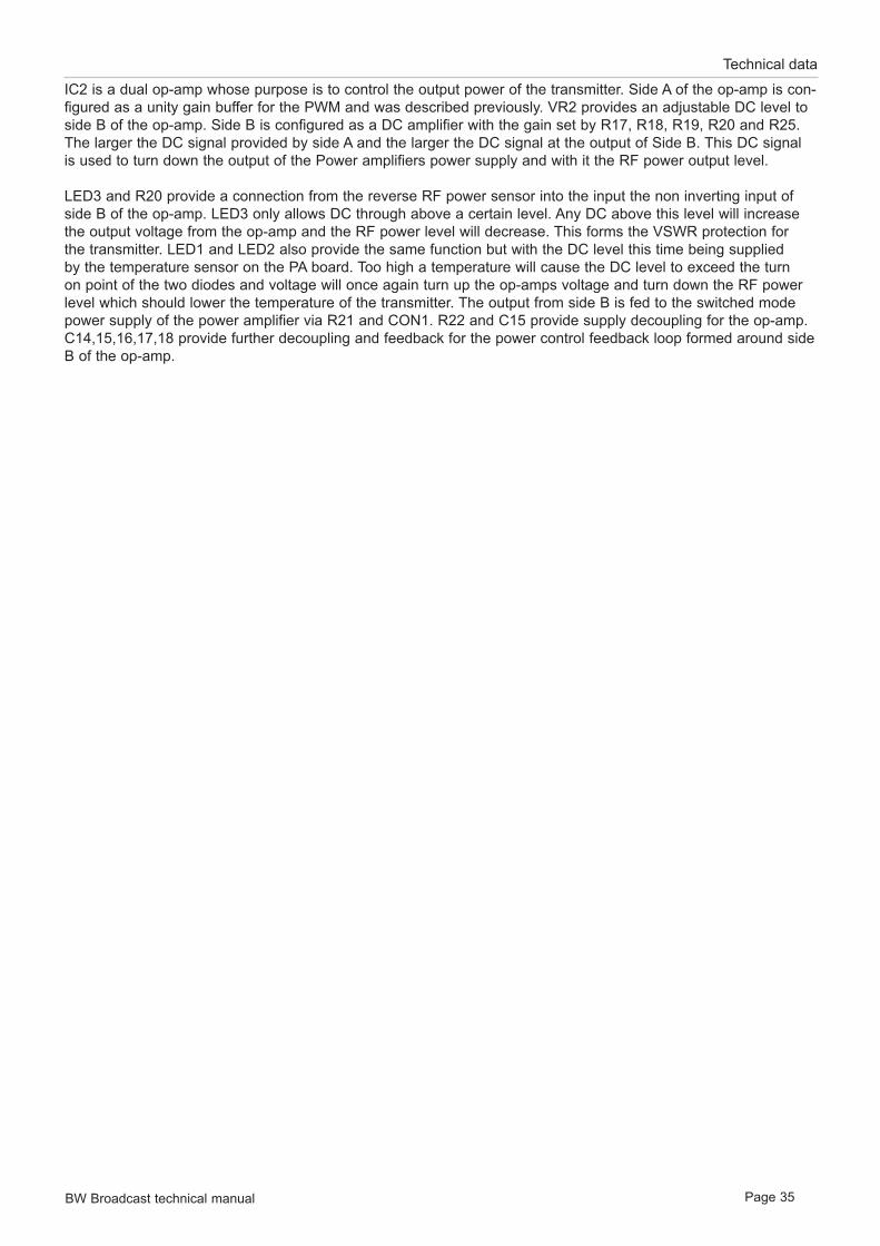
BW Broadcast technical manual Page 35
Technical data
IC2 is a dual op-amp whose purpose is to control the output power of the transmitter. Side A of the op-amp is con-figured as a unity gain buffer for the PWM and was described previously. VR2 provides an adjustable DC level to side B of the op-amp. Side B is configured as a DC amplifier with the gain set by R17, R18, R19, R20 and R25. The larger the DC signal provided by side A and the larger the DC signal at the output of Side B. This DC signal is used to turn down the output of the Power amplifiers power supply and with it the RF power output level.
LED3 and R20 provide a connection from the reverse RF power sensor into the input the non inverting input of side B of the op-amp. LED3 only allows DC through above a certain level. Any DC above this level will increase the output voltage from the op-amp and the RF power level will decrease. This forms the VSWR protection for the transmitter. LED1 and LED2 also provide the same function but with the DC level this time being supplied by the temperature sensor on the PA board. Too high a temperature will cause the DC level to exceed the turn on point of the two diodes and voltage will once again turn up the op-amps voltage and turn down the RF power level which should lower the temperature of the transmitter. The output from side B is fed to the switched mode power supply of the power amplifier via R21 and CON1. R22 and C15 provide supply decoupling for the op-amp. C14,15,16,17,18 provide further decoupling and feedback for the power control feedback loop formed around side B of the op-amp.

BW Broadcast technical manual Page 36
Technical data
3.23 POWER AMPLIFIER BOARDThe RF signal from the exciter section of the combo board arrives at the MCX RF input connector CON5 via a coaxial cable. From here the 50 ohm input impedance is matched to the gate of the FET transistor T1 by the impedance matching network formed by C8, C9, C30, L1 and L7. R26, R22, VR2 and C10 provide bias control to the gate of T1.
FB, L2 and L2 provide 24 volts to T1’s drain from the 24 volt line as well as providing some impedance matching to the output of T1. The RF output is fruther fed into a low pass filter composed of C17 to C24 and inductors L3 to L5. These components reduce the level of any harmonic products generated by the power amplifier. The output of the low pass filter feeds into the VSWR sensor which generates our forward and reverse RF power measurements for metering and for VSWR fault protection and alarms. The RF line passes through ferrite ring RFT1. IC1 and associated resistors R2-R12 buffer the sensors outputs and provide a level suitable for the control/LCD boards microcontroller and protection circuitry.
The RF output sniff for the front panel is formed by a potential divider from the RF output line. This potential divid-er is formed by resistors R1 and R2. A coaxial cable connects the potentially divided RF output to the front panel.
A temperature sensor circuit is located close to the main RF transistor T1. This temperature sensor is mounted into the heatsink and consists of the sensor itself TS1 which is located under the board and an op-amp circuit for level adjustment. The op-amp IC2 and associated components convert the output signal from the sensor itself to a level more suitable for the microcontroller and protection circuitry on the Control / LCD board.
CON2 connection block provides an interface to the board for the power connections from the two power supply modules and an interface to the LCD control board. This connector carries readings for the forward and reverse power, temperature, PA voltage, 18 volts from the regulator off the AUX power line to power the LCD control board and the combo board, and last but not least the PA power modules control line which controls it’s output voltage.
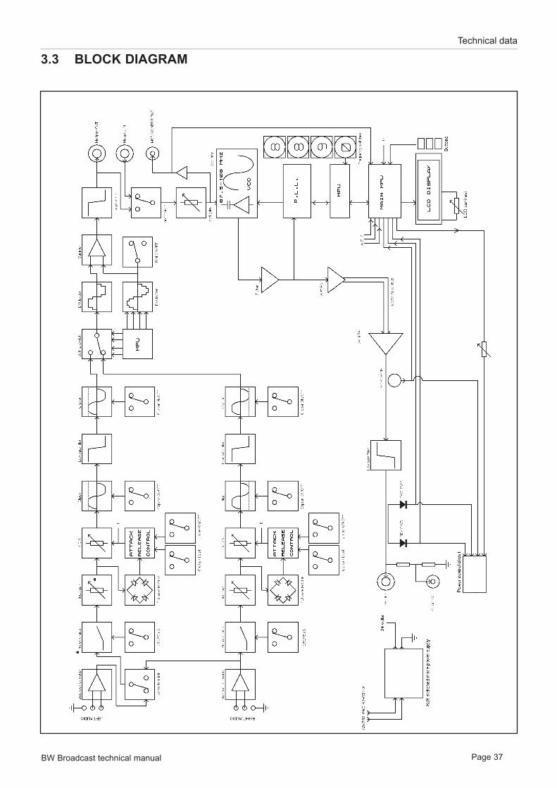
BW Broadcast technical manual Page 37
Technical data
3.3 BLOCK DIAGRAM

BW Broadcast technical manual Page 38
Technical data
3.4 WIRING AND INTERNAL OVERVIEW
5W P
A B
OA
RD
LCD
bo
ard
CONTROL / POWER / EXCITER SECTION
AUDIO INPUT / LIMITER SECTION STEREO ENCODER SECTION
Co
mb
o b
oar
d
BN
CB
NC
XLR
XLR
9-p
in D
-Typ
es
(Ala
rms
& R
S232
)
N-t
ype
sock
et
EART
H
Filt
ered
IEC
mai
ns
sock
et 24 V
co
mb
o
po
wer
su
pp
lyW
7W
8W
1W
3W
2
RF &
MO
D
MO
N B
NC
’s
16 WY RIBBON
10 WY RIBBON
RG31
6RG
316
RG31
6 RG
316
BLA
CK
RED
W1
yello
w/g
reen
16/
0.2
W2
blue
24/
0.2
W3
brow
n 24
/0.2
W7
blac
k 24
/0.2
W8
red
24/0
.2
W1
W2
W3

BW Broadcast technical manual Page 39
Technical data
3.51 COMBO BOARD SCHEMATICS
3.511 Limiter section
TITL
E:
BY:
DA
TE:
PA
GE
:
LIM
ITER
SEC
TIO
N18
/04/
08
S.I.
1/1
RE
V:
1
R68
VR
2
VR
4
LEFT
IN
HO
T
CO
LD
GN
D
CO
N5
R66
R72
C48
C47
R65
321
84
IC3:
A
C39
R67
R71
567
IC3:
BR
69
C43
R70
R75
R73
567
IC9:
B
567
IC9:
B
D9
D11R
74R
76C
53
R77
R78
D6
R64 1514 13
16
11
IC5:
B
R53
R48
567
IC8:
B
321
84
IC8:
A
D1
D2R
49R
54C
49
R56
R57
D4
R47
VR
1
VR
3
LEFT
IN
HO
T
CO
LD
GN
D
CO
N4
R44
R50
C46
C45
R45
321
84
IC2:
A
C38
R46
R51
567
IC2:
BR
53
C42
R52
R63 23 4
1
6
5
12
IC5:
A
C55
C54
R59 R58
R60
3 21
8 4
IC7:
1
D5
D7
567
IC7:
B
D12
C56
567
IC6:
B
321
84
IC6:
A
R62
R61
D3
D10
C52 C
50
T2 T1
R80
R81
C57
R79
LED
2
LED
1
LEFT
AU
DIO
TO
RIG
HT
AU
DIO
TO
PRO
CES
S
CLI
P
PRO
CES
S
CLI
P
PRE
EMPH
ASI
SIN
PUT
LEV
EL
5075
5075
PRE
EMPH
ASI
SIN
PUT
LEV
EL
-15
+15
BR
IDG
EM
ON
O F
RO
M L
EFT
J3
J12
J2
J7
J5
D8
+15
+15
-15
+15
+15
+15
-15
-15V
+15V
-15
-15
J6
J4
CO
DER
SEC
TIO
N
CO
DER
SEC
TIO
N
LIM
ITER
J8
R10
9
CO
N8
/ 3LI
M G
/R O
UT
ON
OFF
R11
7
R11
8+
3
-2
6
IC4
R11
6
R11
9
+3
-2
6
IC1
R11
2
R11
3
R11
4
R11
5
51K
RE
TRO
FIT

BW Broadcast technical manual Page 40
Technical data
15KH
Z LP
F
INOUT
FIL2
R87
R88C65
LED
4
R89
+3
-2
6
1
8IC11 C
59
VCC+13 GND 5
VCC-VD+12
2 1 7 8 10 9 15 16
3 6 11 14
IC12
C63
15KH
Z LP
F
INOUT
FIL1
R83C64
LED
3
R84
+3
-2
6
1
8
IC10
C58
C62
R86
8 B
IT P
ICM
ICR
O
RTCC
3
RA0
17
RA1
18RA2
1
RA3
2
RB0
6
RB1
7
RB2
8
RB3
9RB4
11RB5
10
RB7
13
MCLR
4
OSC
116
RB
612
GN
D5
VC
C+
14O
SC2
15
IC13
R90
R98
R91
R92
R93
VR6
R102
R101
+3
-2
6
IC14
R103
C75
R104
R105 C79
C78
C80
C81-82C83
L1L2
C84
+3
-2
6
1
8
IC15
R107
C86
R106
R108
MPX
OU
TPU
T
X1
C73
+5V
+5V
-12V
+5V
+12V
15 K
HZ
CLI
P JU
MPE
R
15 K
HZ
CLI
P JU
MPE
R
STER
EO/M
ON
O
R82
CO
N3
LEFT
INPU
T FR
OM
LIM
ITER
SEC
TIO
N
RIG
HT
INPU
T FR
OM
LIM
ITER
SEC
TIO
N
R85
J9 J10
R97
R96
R95
R94
R99
R100
C74
PILO
T FI
NE
TUN
E
J11
MPX
LO
OPT
HR
OU
GH
J1
TO E
XC
ITER
C94
15kH
z Fi
lter B
lock
+5V
+12V
3.512 Stereo encoder section

BW Broadcast technical manual Page 41
Technical data
3.513 PLL exciter section
B
B
A A
TITL
E:
BY:
DA
TE:
PA
GE
:
EX
CIT
ER
/ P
SU
/ C
ON
TRO
L17
/04/
08
S.I.
1/1
RE
V:
1
T5 T4
R22
R23
R21
R25 C
24
C23
R27
R19
R20
C21
VD
1
L3C
14
R18
C20
T6C
27
R11
0
T7
R30
R28
C25
L5
C29
R31
L4L5
C30
C32
C33
C34
C31
C28
C19
C22
326
7415
IC20
R17
R16
R15
R7 R
8
X1
Y2
C13
IC1:
A
X11
Y10
C 12
IC19
:B
R5
R6
1612
f R9
V15
R14
PD
13
OS
C in
1
OS
C o
ut2
RE
F ou
t3
F in
4
D in
5E
NB
6C
LK7
D o
ut8
f V10
LD11
IC18
8 BIT P
ICM
ICR
O
RTC
C3
RA
017
RA
118
RA
21
RA
32
RB
06
RB
17
RB
28
RB
39
RB
411
RB
510
RB
713
MC
LR4
OS
C1
16
RB
612
GN
D5
VC
C+
14O
SC
215
IC17
C1
X2
C4
D15
-30
VC
1
C15
R24
C16
5V
RF
OU
TPU
T
+15
VD
C
5V
R13
R29
D23
+15
VD
C
R31
X1
Y2
C13
IC19
:A
R9
10V
+10
VD
C
5V
C12
C6
C9
C8
C17
C18
C13
09
8
4
13
2
56
7
SW1
09
8
4
13
2
56
7
SW2
09
8
4
13
2
56
7
SW3
C7
RFT
1
R12
LED
5
VO
LTR
EG
OU
T
COM
INR
EG
3
321
84
IC18
:A
567 IC
18:B
R40
C35
R39
VR
5 R42
R41
C37
CO
N7
T3
R11
R10
C10
5V
12
CO
N2
1312
CO
N8
MU
LTIP
LEX
INP
UT
/ BN
C
CO
N8
BU
FFE
RE
D M
OD
.
IN
OUT+
GND
OUT-
DC
1
VO
LTR
EG
OU
T
COM
IN
U1
D13
L7 L8C89
C1
C91
C4
-16V
DC
+16V
DC
VO
LTR
EG
OU
T
COM
IN
U2
+5 V
DC
C2
CO
N6
18 V
DC
IN
2 3 10 11 9 1
10 11 12 13
4T9
T8T1
0
5 6 7
R32
R34
R35
R36
R37
R33
19 2
RS232 / CONTROL CO
N1
8
CO
N8
R38
RF MUTEO / C SIGNALS
TTL SIGS
CO
N8
8 A
ND
16
6 A
ND
7
CO
N8
CO
N8
VO
LTR
EG
OU
T
COM
INR
EG
4
VO
LTR
EG
OU
T
COM
INR
EG
5
C67
C70
C72
C90
C77
-12
VD
C
+12
VD
C
09
8
4
13
2
56
7
SW4
R1
R3R2
R4
C5
R11
1
R43 R
121
C43
+- CO
N9
FRO
NT
PA
NE
L M
OD
MO
N
15R
120
+18
R12
6
C97
C3
L11
L9
R14
T11
L1

BW Broadcast technical manual Page 42
Technical data
3.52 LCD CONTROL BOARD
BW Broadcast technical manual Page 43
Technical data
3.53 Power amplifier board
GN
D
+Vin
Vin
1
GN
D
3
GN
D
5
Vre
f
4Pou
t2
RE
G1
C1
CO
N2-
10
CO
N2-
5
CO
N2-
4
CO
N2-
3
C2
C3
C28
D1L6
C4
C5
R27
R26
C29
T1L1
C8
C9
1
2
CO
N5
D2
R25
FB
L2 0.33
uH
C6
C7
L3L4
L5
C24
C23
C21
C20
C22
C19
C18
C17C
16
3 21
8 4
U2:
A5 6
7
8 4
U2:
B
R14R15
R13
R19
C25R18
C26
V-
3V
+2
ADJ 1
TS1
R16
R17
1
2
CO
N3
RFT
1
C11
C12
R8
D4
D3
R7
R6
R20
R21
C27
R10
C14
R3
C13
3 21
8 4
U1:
A5 6
7
8 4
U1:
B
R11
VR
1
R12
R9
C15
R4
R5
CO
N1+
CO
N1-
CO
N2-
9
CO
N2-
2
CO
N2-
6
CO
N2-
1
CO
N2-
7
R2
R1
1
2
CO
N4
FM5
POW
ER A
MPL
IFIE
RTi
tle :
By
: H
.C.R
.
Dat
e :
Page
:
11/0
4/20
08
1 of
1
Dis
play
+V
VI1 VO 3
GN
D2
RE
G2
CO
N
L7
C30
R22
C10
VR
2R
26
RR

BW Broadcast technical manual Page 44
Technical data
3.6 PARTS LIST
3.61 Combo board
Qty Reference Value Description10 C1, C2, C5, C8, C9, C13, C72, C74,
C77, C91 2.2uF 50V Miniature Radial Electrolytic - 4-5mm Dia, 2mm Pitch, Tolerance +- 20%
1 C7 470uF 16V Non-Polarized Electrolytic Capacitor1 C27 82pF Ceramic Plate 2.5mm pitch (680 Series)
3 C17, C18, C96 100uF 16V Miniature Radial Electrolytic - 6mm Dia, 2.5mm Pitch, Tolerance +- 20%
3 C25, C29, C33 1n General Purpose Ceramic Disc 2.5mm pitch2 C97, C14 2n2 Ceramic Plate 2.5mm pitch (629 Series)1 C15 220pF Low K Ceramic capacitor1 C95 220pF General Purpose Ceramic Disc 2.5mm pitch1 C21 3p9 General Purpose Ceramic plate 2.5mm pitch6 C22, C30, C49, C53, C58, C59 27pF Ceramic Plate 2.5mm pitch (680 Series)1 C32 68pF Ceramic Plate 2.5mm pitch (680 Series)1 C23 39pF Ceramic Plate 2.5mm pitch (680 Series)2 C10, C24 2n2 Ceramic Plate 2.5mm pitch (680 Series)
21C3, C11, C16, C19, C26, C28, C36, C40, C41, C44, C51, C60, C61, C66, C68, C69, C71, C76, C85, C87, C92
100n Y5V Radial Multilayer Ceramic 2.5mm pitch - Y5V Dielectric
5 C99, C100, C101, C102, C103 1uF Y5V Radial Multilayer Ceramic 2.5mm pitch - Y5V Dielectric
2 C79, C98 100nF Miniature Polyester Capacitor 5mm pitch (Dubilier DMP5 Series)
1 C31 15pF Ceramic Plate 2.5mm pitch (680 Series)2 C75, C86 12pF Ceramic Plate 2.5mm pitch (680 Series)8 C4, C38, C39, C42, C43, C50, C52,
C56 47pF General Purpose Ceramic Disc 2.5mm pitch2 C73, C94 33pF General Purpose Ceramic Disc 2.5mm pitch2 C34, C20 47pF Ceramic Plate 2.5mm pitch (680 Series)2 C46, C47 6n8 Polyester 5mm pitch 250V DC2 C45, C48 4n7 Polyester 5mm pitch 250V DC7 C54, C57, C62, C63, C67, C70, C88 47uF 16V Miniature Radial Electrolytic - 5mm Dia, 2mm Pitch, Tolerance +-
20%3 C55, C93, C12 10uF 16V Miniature Radial Electrolytic - 4-5mm Dia, 2mm Pitch, Tolerance
+- 20%
3 C6, C89, C90 470uF 16V Radial Electrolytic - 8mm Dia, 3.5mm Pitch, Tolerance +- 20% (Forever RB Series)
6 C64, C65, C78, C81, C82, C84 330pF Ceramic Plate 2.5mm pitch Capacitor1 C80 100pF General Purpose Ceramic Disc 2.5mm pitch1 C104 120pF Ceramic Plate 2.5mm pitch
1 VC1 5-65pF Variable Capacitor - 100V DC, Dia 10.5mm, Pitch 7.62x5.08mm- (BC 808 Series)
N.F C35, C37, C83 n/a Not fitted1 D13 1N4001 Axial 1 Amp Silicon Rectifier Diode - DO41 Packate 0.8mm leads
29 D1-D12,D15-D30, D31 1N4148 Glass Axial General Purpose Diode - DO-35 Package4 LED1-4 GREEN Bi Directional 5mm Green LED - Vf 2.2V - (Kingbright L-57D Series)1 LED5 RED 5mm Pitch Standard Red LED (eg Kingbright L-53 Series)1 VD1 BB809 ** VHF Varicap Diode1 L1 3.9mH Radial Inductor (Toko 8RBS) #181LY-392J1 L2 4.7mH Radial Inductor (Toko 10RB) #181LY-472J1 L3 MC100 075 Screened Variable Inductor (MC120) #E526HNA-1000751 L4 MC100 112 Screened Variable Inductor (MC120) - #E526HNA-1001121 L5 MC120 073 Screened Variable Inductor - (MC120) #E526HNA-100073 1 L6 0.33uH Axial Inductor Body 7mm, Dia 2.8mm

BW Broadcast technical manual Page 45
Technical data
2 L9, L10 0.15uH Axial Inductor Body 7mm, Dia 2.8mm - Sigma Inductors (C30 Series 0.25W)
2 L7,L8 220uH Axial Inductor Body 9.2mm, Dia 4.0mm - Epcos Inductors (B78108S Series RF Inductors)
1 L11 MC141- 100 110 Screened Variable Inductor - (MC141) #NE547SNAS-100110
1 CON1 15 Way D Right Angled Female Dual Double Height D-Type PCB-Mount Connector
2 CON2, CON3 R/A BNC Right Angled BNC PCB-Mount Connectors2 CON4, CON5 R/A XLR Right Angled XLR PCB-Mount Connectors (F3FRAF)0 CON6 2 Term 2 Way Screwless Terminal (Mask off, & do not fit)3 CON7, CON9, CON13 MCX MCX PCB Mount Socket1 CON8 16 way Straight IDC Header3 CON10, CON11, CON12 4-way 4 Pin Jumber Header1 DC1 B31215S Bothand 2W Dual Output DC Converter1 FB n/a Radial Axial Ferrite Bead1 FIL1-2 5085 15kHz Block Filter- Separate board1 Heatsink TO5 T05 Heatsink - Height 12.7mm (Aavid Thermalloy 5F)1 IC Holders (14 pin) IC19, 14 pin IC Holder - Dual wipe contacts - eg Eurocon TS1001-xx4 IC Holders (16 pin) IC18, IC12, IC5,
IC21 16 pin IC Holder - Dual wipe contacts - eg Eurocon TS1001-xx2 IC Holders (18 pin) IC13, IC17 18 pin IC Holder - Dual wipe contacts - eg Eurocon TS1001-xx
14IC Holders (8 pin) IC1, IC2, IC3, IC4, IC6, IC7, IC8, IC9, IC10, IC11, IC14, IC15, IC16, IC20
8 pin IC Holder - Dual wipe contacts - eg Eurocon TS1001-xx
12 J1-12 3 pin 3 Pin Jumper Header - (2.54mm 3-Way Row)12 J1-12 LINKS n/a Jumper Link 2.54mm - Protech ‘Easy Pull’ Style1 RFT1 1 Turn 1 Complete Turn Ferrite Core4 SW1-4 Dec Rota Decimal Rotary PCB Switches1 X1 4.864Mhz HC49 Micro Crystal1 X2 8.000MHz HC49 Micro Crystal
1 RFT1 Wire 28Gauge Twist Approx 3cm lengh per coil- 28 Guage Self fluxing wire
1 R126 330uH Axial Inductor7 R1, R2, R3, R4, R5, R6, R9 10K 1/8 Watt Carbon Film - Tolerance +- 5%1 R10 470R 1/8 Watt Carbon Film - Tolerance +- 5%1 R100 1M 1/4 Watt Metal Oxide - Tolerance +- 1%
10 R101, R110, R112, R113, R114, R115, R116, R117, R118, R119 10K 1/4 Watt Metal Oxide - Tolerance +- 1%
3 R103, R47, R68 5K1 1/4 Watt Metal Oxide - Tolerance +- 1%1 R106 3K6 1/4 Watt Metal Oxide - Tolerance +- 1%1 R107 12K 1/4 Watt Metal Oxide - Tolerance +- 1%1 R11 33K 1/8 Watt Carbon Film - Tolerance +- 5%
9 R12, R13, R17, R32, R33, R34, R35, R36, R37 1K2 1/8 Watt Carbon Film - Tolerance +- 5%
2 R22, R23 1K2 1/4 Watt Metal Oxide - Tolerance +- 1%2 R15, R16 680R 1/8 Watt Carbon Film - Tolerance +- 5%1 R18 100R 0.4 Watt Carbon Film - Tolerance Low Noise1 R105 100R 1/4 Watt Metal Oxide - Tolerance +- 1%1 R19 12K 1/4 Watt Metal Oxide - Tolerance +- 1%3 R20, R26, R29 4K7 1/4 Watt Metal Oxide - Tolerance +- 1%3 R21, R57, R78 220R 1/4 Watt Metal Oxide - Tolerance +- 1%1 R30 220R 1/8 Watt Carbon Film - Tolerance +- 5%1 R24 68R 1/4 Watt Metal Oxide - Tolerance +- 1%1 R25 300R 1/4 Watt Metal Oxide - Tolerance +- 1%2 R28, R132 22R 1/4 Watt Metal Oxide - Tolerance +- 1%1 R31 4R7 1/4 Watt Metal Oxide - Tolerance +- 1%1 R39 2k2 1/4 Watt Metal Oxide - Tolerance +- 1%

BW Broadcast technical manual Page 46
Technical data
8 R40, R45, R51, R65, R71, R94, R98, R125 1k 1/4 Watt Metal Oxide - Tolerance +- 1%
1 R41 560R 1/4 Watt Metal Oxide - Tolerance +- 1%1 R42 820R 1/4 Watt Metal Oxide - Tolerance +- 1%3 R43, R108, R121 75R 1/4 Watt Metal Oxide - Tolerance +- 1%
9 R44, R54, R60, R66, R76, R79, R86, R91, R96 12K 1/4 Watt Metal Oxide - Tolerance +- 1%
2 R61, R62 7K5 1/4 Watt Metal Oxide - Tolerance +- 1%
10 R48, R49, R55, R56, R58, R73, R74, R75, R77, R102 24K 1/4 Watt Metal Oxide - Tolerance +- 1%
4 R27, R50, R85, R72 470R 1/4 Watt Metal Oxide - Tolerance +- 1%3 R59, R97, R104 3K3 1/4 Watt Metal Oxide - Tolerance +- 1%
2 R52, R70 WLNK - 0/Ohms WLNK - Wire Link across pads (use other resistor legs)
2 R53, R69 100K 1/4 Watt Metal Oxide - Tolerance +- 1%2 R63, R64 16K 1/4 Watt Metal Oxide - Tolerance +- 1%3 R7, R8, R14 330K 1/8 Watt Carbon Film - Tolerance +- 5%2 R80, R81 470K 1/4 Watt Metal Oxide - Tolerance +- 1%3 R83, R88, R99 6K8 1/4 Watt Metal Oxide - Tolerance +- 1%5 R38, R84, R89, R120, R131 10R 1/4 Watt Metal Oxide - Tolerance +- 1%2 R82, R87 13K 1/4 Watt Metal Oxide - Tolerance +- 1%1 R90 5K6 1/4 Watt Metal Oxide - Tolerance +- 1%4 R92, R111, R46, R67 47K 1/4 Watt Metal Oxide - Tolerance +- 1%2 R93, R109 120K 1/4 Watt Metal Oxide - Tolerance +- 1%1 R95 4K3 1/4 Watt Metal Oxide - Tolerance +- 1%1 R128 51R 1/4 Watt Metal Oxide - Tolerance +- 1%2 R129, R130 4k7 1/4 Watt Metal Oxide - Tolerance +- 1%3 R133, R134 470R 0.6 Watt Metal Oxide - Tolerance +- 1%3 VR1,VR2,VR5 10K Horizontal Multiturn (Bourns 3006P Series)2 VR3,VR4 1K Vertical Multiturn (Bourns 3296W Series - Top screw adjustment)1 VR6 10K Vertical 5mm Pitch (Spectrol 63M Series - Top screw adjustment)1 VR7 200R Vertical 5mm Pitch 63M - Top screw adjustment)2 R122, R123 1k 1/8 Watt Carbon Film - Tolerance +- 5%1 R127 180R 1/8 Watt Carbon Film - Tolerance +- 5%1 R124 1K3 1/4 Watt Metal Oxide - Tolerance +- 1%6 IC1, IC4, IC10, IC11, IC14, IC15 TL071 Low Noise Op Amp
1 IC12 DG201-HS (HI3) HI3-0201HS-5Z Analog Switch
1 IC13 PIC16C620A-04P 8 Bit Microcontroller
1 IC17 PIC16CE624-20P 8 Bit Microcontroller
1 IC18 MC145170-P ** PLL Synthesiser 1 IC19 4066 Analog Switch7 IC2, IC3, IC6, IC7, IC8, IC9, IC16 TL072 Low Noise Dual Op Amp1 IC20 LF351 Bi-FET Op Amp1 IC5 LM13700N Transconductance Amplifier1 IC21 ST232CN ST232CN RS232 TRANSCIEVER1 REG1 7815 1A TO220 15V Linear Regulator1 REG2 7805 1A TO220 5V Linear Regulator
2 T1,T2 BC327 (C3271) BC327-16 TO92 50V PNP GP TRANSIST
4 T3,T4,T5,T6 MPSH10 High Speed Switching Transistor1 T11 ZVN4306A Zetec Transistor1 T7 2N4427 High Speed Switching Transistor APT3 T8,T9,T10 BC337 (C3371) C337-16 TO92 50V NPN GP TRANS

BW Broadcast technical manual Page 47
Technical data
3.62 LCD control board
Qty Reference Value Description4 C1, C2, C13, C18 2.2uF 63V Electrolytic Cap2 C12, C15 100n 2.5mm Pitch Radial Multilayer Ceramic ( Y5V )2 C3, C4 33pF 33pF Ceramic 2.5mm Pitch
10 C5, C6, C7, C8, C9, C10, C11, C14, C16, C17 560pF 560pF Ceramic1 D1 1N4148 1N41481 LED1 3mm Mini 3mm Green LED - L-7104GD 1 LED2 3mm Mini 3mm Red LED - L-7104GD 3 R1, R2, R16 33k 1/8 W Metal Film 1% - CR123 R12, R13, R14 1k8 1/8 W Metal Film 1% - CR124 R15, R18, R20, R22 100R 1/8 W Metal Film 1% - CR121 R17 560R 1/8 W Metal Film 1% - CR121 R19 100k 1/8 W Metal Film 1% - CR126 R3, R7, R8, R9, R10, R11 820R 1/8 W Metal Film 1% - CR122 R4, R5 390R 1/8 W Metal Film 1% - CR121 R6 10k 1/8 W Metal Film 1% - CR121 R21 4k7 1/8 W Metal Film 1% - CR121 R23, R24 4R7 1/8 W Metal Film 1% - CR121 R25 1K 1/8 W Metal Film 1% - CR121 VR3 200R Bourns 3296 W 3/8in1 VR1 500R Bourns Minipot1 VR2 100k Minipot Spectrol 63M1 Reg1 7805 7805CV 1A VOLTAGE REGULATOR 1 IC1 40 Pin 40 Pin PIC16F877-20P (NOT FITTED)1 IC2 CA3240EZ CA3240 Op Amp0 IC3 TBA NOT FITTED3 SW1-3 9.5mm 9mm Tactile Switch1 X1 8MHz 8MHz Crystal1 Connector 20-Way Header Strip (20-Way)1 LCD Screen LCD Blue LCD Display
1 IC1 40-Pin 40 Pin IC Socket2 IC2,IC3 8-Pin 8-Pin IC Socket3 Panel Buttons n/a Molded Cap for Switch (NOT FITTED)1 Con1 10-Way 10 Way Boxed Header1 Con2 16-Way 16 Way Boxed Header
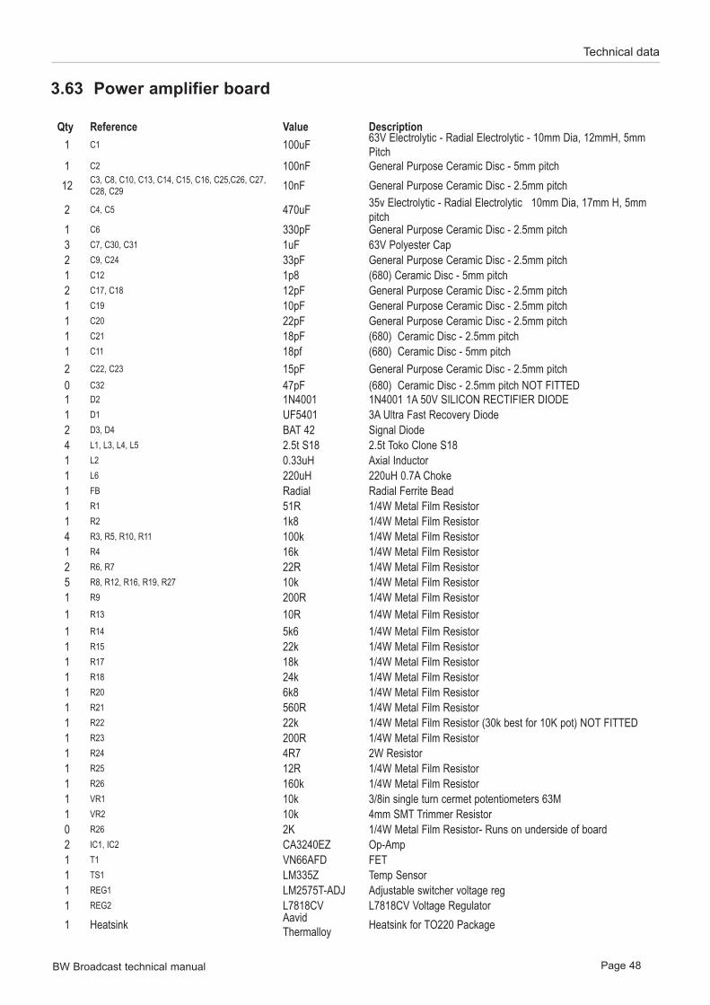
BW Broadcast technical manual Page 48
Technical data
3.63 Power amplifier board
Qty Reference Value Description1 C1 100uF 63V Electrolytic - Radial Electrolytic - 10mm Dia, 12mmH, 5mm
Pitch1 C2 100nF General Purpose Ceramic Disc - 5mm pitch
12 C3, C8, C10, C13, C14, C15, C16, C25,C26, C27, C28, C29 10nF General Purpose Ceramic Disc - 2.5mm pitch
2 C4, C5 470uF 35v Electrolytic - Radial Electrolytic 10mm Dia, 17mm H, 5mm pitch
1 C6 330pF General Purpose Ceramic Disc - 2.5mm pitch 3 C7, C30, C31 1uF 63V Polyester Cap 2 C9, C24 33pF General Purpose Ceramic Disc - 2.5mm pitch 1 C12 1p8 (680) Ceramic Disc - 5mm pitch 2 C17, C18 12pF General Purpose Ceramic Disc - 2.5mm pitch 1 C19 10pF General Purpose Ceramic Disc - 2.5mm pitch 1 C20 22pF General Purpose Ceramic Disc - 2.5mm pitch 1 C21 18pF (680) Ceramic Disc - 2.5mm pitch 1 C11 18pf (680) Ceramic Disc - 5mm pitch 2 C22, C23 15pF General Purpose Ceramic Disc - 2.5mm pitch 0 C32 47pF (680) Ceramic Disc - 2.5mm pitch NOT FITTED1 D2 1N4001 1N4001 1A 50V SILICON RECTIFIER DIODE 1 D1 UF5401 3A Ultra Fast Recovery Diode2 D3, D4 BAT 42 Signal Diode4 L1, L3, L4, L5 2.5t S18 2.5t Toko Clone S181 L2 0.33uH Axial Inductor1 L6 220uH 220uH 0.7A Choke1 FB Radial Radial Ferrite Bead1 R1 51R 1/4W Metal Film Resistor1 R2 1k8 1/4W Metal Film Resistor4 R3, R5, R10, R11 100k 1/4W Metal Film Resistor1 R4 16k 1/4W Metal Film Resistor2 R6, R7 22R 1/4W Metal Film Resistor5 R8, R12, R16, R19, R27 10k 1/4W Metal Film Resistor1 R9 200R 1/4W Metal Film Resistor1 R13 10R 1/4W Metal Film Resistor1 R14 5k6 1/4W Metal Film Resistor1 R15 22k 1/4W Metal Film Resistor1 R17 18k 1/4W Metal Film Resistor1 R18 24k 1/4W Metal Film Resistor1 R20 6k8 1/4W Metal Film Resistor1 R21 560R 1/4W Metal Film Resistor1 R22 22k 1/4W Metal Film Resistor (30k best for 10K pot) NOT FITTED1 R23 200R 1/4W Metal Film Resistor1 R24 4R7 2W Resistor1 R25 12R 1/4W Metal Film Resistor1 R26 160k 1/4W Metal Film Resistor1 VR1 10k 3/8in single turn cermet potentiometers 63M1 VR2 10k 4mm SMT Trimmer Resistor0 R26 2K 1/4W Metal Film Resistor- Runs on underside of board 2 IC1, IC2 CA3240EZ Op-Amp1 T1 VN66AFD FET1 TS1 LM335Z Temp Sensor1 REG1 LM2575T-ADJ Adjustable switcher voltage reg1 REG2 L7818CV L7818CV Voltage Regulator1 Heatsink Aavid
Thermalloy Heatsink for TO220 Package

BW Broadcast technical manual Page 49
Technical data
2 ICH1, ICH2 8 Pin IC Holder 8 Pin IC Holder1 Con1 2-Way 2-way screwless terminal 45deg conn1 Con2 10-Way 10-Way IDC Header3 Con3, Con4, Con5 MCX MCX PCB Mount Connector
1 RFT1 Ferrite Core TFR Yellow/Red Ferrite Core S37-8/90
1 RFT1 Scientific Wire Self Fluxing Enamelled Copper Wire 1 RFT1 Semi Rigid
Coax 50Ohm Semi-Rigid Coax EZ50-.090 - 28mm
1 INS Ceramic Insulator Ceramic insulator
1 MOD 2n2 R23 to ground

www.bwbroadcast.com