
Two-Way Flat Slab (Concrete Floor with Drop Panels) System ... · Two-Way Flat Slab (Concrete Floor...
80
Two-Way Flat Slab (Concrete Floor with Drop Panels) System Analysis and Design
Transcript of Two-Way Flat Slab (Concrete Floor with Drop Panels) System ... · Two-Way Flat Slab (Concrete Floor...

Two-Way Flat Slab (Concrete Floor with Drop Panels) System Analysis and Design

Two-Way Flat Slab (Concrete Floor with Drop Panels) System Analysis and Design
Design the concrete floor slab system shown below for an intermediate floor considering partition weight = 20 psf,
and unfactored live load = 60 psf. The lateral loads are independently resisted by shear walls. The use of flat plate
system will be checked. If the use of flat plate is not adequate, the use of flat slab system with drop panels will be
investigated. Flat slab concrete floor system is similar to the flat plate system. The only exception is that the flat slab
uses drop panels (thickened portions around the columns) to increase the nominal shear strength of the concrete at the
critical section around the columns. The Equivalent Frame Method (EFM) shown in ACI 318 is used in this example.
The hand solution from EFM is also used for a detailed comparison with the model results of spSlab engineering
software program.
Figure 1 - Two-Way Flat Concrete Floor System

Contents
1. Preliminary member sizing ...................................................................................................................................... 1
2. Flexural Analysis and Design................................................................................................................................. 10
2.1. Equivalent Frame Method (EFM) ................................................................................................................... 10
2.1.1. Limitations for use of equivalent frame method................................................................................... 11
2.1.2. Frame members of equivalent frame .................................................................................................... 11
2.1.3. Equivalent frame analysis .................................................................................................................... 14
2.1.4. Factored moments used for Design ...................................................................................................... 16
2.1.5. Factored moments in slab-beam strip ................................................................................................... 18
2.1.6. Flexural reinforcement requirements.................................................................................................... 19
2.1.7. Factored moments in columns .............................................................................................................. 22
3. Design of Columns by spColumn .......................................................................................................................... 24
3.1. Determination of factored loads ...................................................................................................................... 24
3.2. Moment Interaction Diagram .......................................................................................................................... 26
4. Shear Strength ........................................................................................................................................................ 29
4.1. One-Way (Beam action) Shear Strength ......................................................................................................... 29
4.1.1. At distance d from the supporting column ........................................................................................... 29
4.1.2. At the face of the drop panel ................................................................................................................ 30
4.2. Two-Way (Punching) Shear Strength ............................................................................................................. 31
4.2.1. Around the columns faces .................................................................................................................... 31
4.2.2. Around drop panels .............................................................................................................................. 34
5. Serviceability Requirements (Deflection Check) ................................................................................................... 39
5.1. Immediate (Instantaneous) Deflections ........................................................................................................... 39
5.2. Time-Dependent (Long-Term) Deflections (Δlt) ............................................................................................. 60
6. spSlab Software Program Model Solution ............................................................................................................. 61
7. Summary and Comparison of Design Results ........................................................................................................ 82
8. Conclusions & Observations .................................................................................................................................. 85

1
Code
Building Code Requirements for Structural Concrete (ACI 318-14) and Commentary (ACI 318R-14)
Reference
Concrete Floor Systems (Guide to Estimating and Economizing), Second Edition, 2002 David A. Fanella
Notes on ACI 318-11 Building Code Requirements for Structural Concrete, Twelfth Edition, 2013 Portland
Cement Association.
Simplified Design of Reinforced Concrete Buildings, Fourth Edition, 2011 Mahmoud E. Kamara and Lawrence
C. Novak
Control of Deflection in Concrete Structures (ACI 435R-95)
Design Data
Story Height = 13 ft (provided by architectural drawings)
Superimposed Dead Load, SDL =20 psf for framed partitions, wood studs, 2 x 2, plastered 2 sides
ASCE/SEI 7-10 (Table C3-1)
Live Load, LL = 60 psf ASCE/SEI 7-10 (Table 4-1)
50 psf is considered by inspection of Table 4-1 for Office Buildings – Offices (2/3 of the floor area)
80 psf is considered by inspection of Table 4-1 for Office Buildings – Corridors (1/3 of the floor area)
LL = 2/3 x 50 + 1/3 x 80 = 60 psf
fc’ = 5000 psi (for slab)
fc’ = 6000 psi (for columns)
fy = 60,000 psi
Solution
1. Preliminary member sizing
For Flat Plate (without Drop Panels)
a. Slab minimum thickness – Deflection ACI 318-14 (8.3.1.1)
In lieu of detailed calculation for deflections, ACI 318 Code gives minimum slab thickness for two-way
construction without interior beams in Table 8.3.1.1.
For this flat plate slab systems the minimum slab thicknesses per ACI 318-14 are:
340Exterior Panels: 11.33 in.
30 30
n
s
lh ACI 318-14 (Table 8.3.1.1)
But not less than 5 in. ACI 318-14 (8.3.1.1(a))
340Interior Panels: 10.3 in.
33 33
n
s
lh ACI 318-14 (Table 8.3.1.1)
But not less than 5 in. ACI 318-14 (8.3.1.1(a))
Where ln = length of clear span in the long direction = 30 x 12 – 20 = 340 in.

2
Try 11 in. slab for all panels (self-weight = 150 pcf x 11 in. /12 = 137.5 psf)
b. Slab shear strength – one way shear
Evaluate the average effective depth (Figure 2):
0.7511 0.75 0.75 9.13 in.
2 2
b
l s clear b
dd h c d
0.7511 0.75 9.88 in.
2 2
b
t s clear
dd h c
9.13 9.889.51 in.
2 2
l t
avg
d dd
Where:
cclear = 3/4 in. for # 6 steel bar ACI 318-14 (Table 20.6.1.3.1)
db = 0.75 in. for # 6 steel bar
Figure 2 - Two-Way Flat Concrete Floor System
Factored dead load, 1.2 (137.5 20) 189 psfDuq
Factored live load, 1.6 60 96 psfLuq ACI 318-14 (5.3.1)
Total factored load, 189 96 285 psfuq
Check the adequacy of slab thickness for beam action (one-way shear) ACI 318-14 (22.5)
at an interior column:
Consider a 12-in. wide strip. The critical section for one-way shear is located at a distance d, from the face
of support (see Figure 3):
230 20 9.51 12Tributary are for one-way shear is 13.37 ft
2 2 12 12 12TributaryA
0.285 13.37 3.81 kipsu u TributaryV q A
'2c c wV f b d ACI 318-14 (Eq. 22.5.5.1)

3
Where 1for normal weight concrete
9.510.75 2 1.0 5000 12 12.09 kips
1000c uV V
Slab thickness of 11 in. is adequate for one-way shear.
c. Slab shear strength – two-way shear
Check the adequacy of slab thickness for punching shear (two-way shear) at an interior column (Figure 4):
2
220 9.51Tributary area for two-way shear is (30 30) 894 ft
12TributaryA
0.285 894 254.78 kipsu u TributaryV q A
'4 (For square interior column)c c wV f b d ACI 318-14 (Table 22.6.5.2(a))
9.51
4 5000 4 20 9.51 317 kips1000
cV
0.75 317 237.8 kipsc uV V
Slab thickness of 11 in. is not adequate for two-way shear.
In this case, three options could be used: 1) to increase the slab thickness, 2) to use headed shear reinforcement, or
3) to use drop panels. In this example, the latter option will be used to achieve better understanding for the design
of two-way slab with drop panels often called flat slab.
Check the drop panel dimensional limitations as follows:
Figure 4 – Critical Section for Two-Way Shear
Figure 3 – Critical Section for One-Way Shear

4
1) The drop panel shall project below the slab at least one-fourth of the adjacent slab thickness.
ACI 318-14 (8.2.4(a))
Since the slab thickness (hs) is 10 in. (see page 6), the thickness of the drop panel should be at least:
0.25 0.25 10 2.5 in.sdp, minh h
Drop panel dimensions are also controlled by formwork considerations. The following Figure shows the
standard lumber dimensions that are used when forming drop panels. Using other depths will unnecessarily
increase formwork costs.
For nominal lumber size (2x), hdp = 4.25 in. > hdp, min = 2. 5 in.
The total thickness including the slab and the drop panel (h) = hs + hdp = 10 + 4.25 = 14.25 in.
Nominal Lumber Size, in. Actual Lumber Size, in. Plyform Thickness, in. hdp, in.
2x 1 1/2 3/4 2 1/4
4x 3 1/2 3/4 4 1/4
6x 5 1/2 3/4 6 1/4
8x 7 1/4 3/4 8
Figure 5 – Drop Panel Formwork Details
2) The drop panel shall extend in each direction from the centerline of support a distance not less than one-
sixth the span length measured from center-to-center of supports in that direction.
ACI 318-14 (8.2.4(b))
1 1 1 130 30 5 ft
6 6 6 61,dp 1 1L L L
1 1 1 130 30 5 ft
6 6 6 62,dp 2 2L L L
Based on the previous discussion, Figure 6 shows the dimensions of the selected drop panels around interior,
edge (exterior), and corner columns.

5
Figure 6 – Drop Panels Dimensions

6
For Flat Slab (with Drop Panels)
For slabs with changes in thickness and subjected to bending in two directions, it is necessary to check shear at
multiple sections as defined in the ACI 319-14. The critical sections shall be located with respect to:
1) Edges or corners of columns. ACI 318-14 (22.6.4.1(a))
2) Changes in slab thickness, such as edges of drop panels. ACI 318-14 (22.6.4.1(b))
a. Slab minimum thickness – Deflection ACI 318-14 (8.3.1.1)
In lieu of detailed calculation for deflections, ACI 318 Code gives minimum slab thickness for two-way
construction without interior beams in Table 8.3.1.1.
For this flat plate slab systems the minimum slab thicknesses per ACI 318-14 are:
340Exterior Panels: 10.30 in.
33 33
n
s
lh ACI 318-14 (Table 8.3.1.1)
But not less than 4 in. ACI 318-14 (8.3.1.1(b))
340Interior Panels: 9.44 in.
36 36
n
s
lh ACI 318-14 (Table 8.3.1.1)
But not less than 4 in. ACI 318-14 (8.3.1.1(b))
Where ln = length of clear span in the long direction = 30 x 12 – 20 = 340 in.
Try 10 in. slab for all panels
Self-weight for slab section without drop panel = 150 pcf x 10 in. /12 = 125 psf
Self-weight for slab section with drop panel = 150 pcf x 14.25 in. /12 = 178 psf
b. Slab shear strength – one way shear
For critical section at distance d from the edge of the column (slab section with drop panel):
Evaluate the average effective depth:
0.7514.25 0.75 0.75 12.38 in.
2 2
b
l s clear b
dd h c d
0.7514.25 0.75 13.13 in.
2 2
b
t s clear
dd h c
12.38 13.1312.75 in.
2 2
l t
avg
d dd
Where:
cclear = 3/4 in. for # 6 steel bar ACI 318-14 (Table 20.6.1.3.1)
db = 0.75 in. for # 6 steel bar

7
Factored dead load 1.2 (178 20) 237.6 psfDuq
Factored live load 1.6 60 96 psfLuq ACI 318-14 (5.3.1)
Total factored load 237.6 96 333.6 psfuq
Check the adequacy of slab thickness for beam action (one-way shear) from the edge of the interior column
ACI 318-14 (22.5)
Consider a 12-in. wide strip. The critical section for one-way shear is located at a distance d, from the edge
of the column (see Figure 7)
230 20 12.75 12Tributary area for one-way shear is 13.10 ft
2 2 12 12 12TributaryA
0.334 13.10 4.37 kipsu u TributaryV q A
2 ' c c wV f b d ACI 318-14 (Eq. 22.5.5.1)
Where 1for normal weight concrete
12.75 0.75 2 1.0 5000 12 16.23 kips
1000cV
uV
Slab thickness of 14.25 in. is adequate for one-way shear for the first critical section (from the edge of the
column).
For critical section at distance d from the edge of the drop panel (slab section without drop panel):
Evaluate the average effective depth:
0.7510 0.75 0.75 8.13 in.
2 2
b
l s clear b
dd h c d
0.7510 0.75 8.88 in.
2 2
b
t s clear
dd h c
8.13 8.888.51 in.
2 2
l t
avg
d dd
Where:
cclear = 3/4 in. for # 6 steel bar ACI 318-14 (Table 20.6.1.3.1)
db = 0.75 in. for # 6 steel bar
Factored dead load 1.2 (125 20) 174 psfDuq
Factored live load 1.6 60 96 psfLuq ACI 318-14 (5.3.1)
Total factored load 174 96 270 psfuq

8
Check the adequacy of slab thickness for beam action (one-way shear) from the edge of the interior drop
panel ACI 318-14 (22.5)
Consider a 12-in. wide strip. The critical section for one-way shear is located at a distance d, from the face
of support (see Figure 7)
230 20 8.51 12Tributary area for one-way shear is 13.46 ft
2 2 12 12TributaryA
0.270 13.46 3.63 kipsu u TributaryV q A
2 ' c c wV f b d ACI 318-14 (Eq. 22.5.5.1)
Where 1for normal weight concrete
8.51 0.75 2 1.0 5000 12 10.82 kips
1000c uV V
Slab thickness of 10 in. is adequate for one-way shear for the second critical section (from the edge of the
drop panel).
Figure 7 – Critical Sections for One-Way Shear
c. Slab shear strength – two-way shear
For critical section at distance d/2 from the edge of the column (slab section with drop panel):
Check the adequacy of slab thickness for punching shear (two-way shear) at an interior column (Figure 8):
2
220 12.75Tributary area for two-way shear is (30 30) 892.6 ft
12TributaryA
0.334 892.6 297.9 kipsu u TributaryV q A

9
4 ' (For square interior column)c c oV f b d ACI 318-14 (Table 22.6.5.2(a))
12.75
4 5000 4 20 12.75 472 kips1000
cV
0.75 472 354 kipsc uV V
Slab thickness of 14.25 in. is adequate for two-way shear for the first critical section (from the edge of the
column).
For critical section at distance d/2 from the edge of the drop panel (slab section without drop panel):
Check the adequacy of slab thickness for punching shear (two-way shear) at an interior drop panel (Figure
8):
2
2120 8.51Tributary area for two-way shear is (30 30) 785 ft
12TributaryA
0.270 785 212.04 kipsu u TributaryV q A
4 ' (For square interior column)c c oV f b d ACI 318-14 (Table 22.6.5.2(a))
8.51
4 5000 4 120 8.51 1236 kips1000
cV
0.75 1236 927 kipsc uV V
Slab thickness of 10 in. is adequate for two-way shear for the second critical section (from the edge of the
drop panel).
Figure 8 – Critical Sections for Two-Way Shear
10
d. Column dimensions - axial load
Check the adequacy of column dimensions for axial load:
Tributary area for interior column for live load, superimposed dead load, and self-weight of the slab is
230 30 900ftTributaryA
Tributary area for interior column for self-weight of additional slab thickness due to the presence of the
drop panel is
210 10 100 ftTributaryA
Assuming five story building
5 0.270 900 0.0638 100 1247 kipsu u TributaryP n q A
Assume 20 in. square column with 4 – No. 14 vertical bars with design axial strength, φPn,max of
,max 0.80 (0.85 ' ( ) )c g st y stnP f A A f A ACI 318-14 (22.4.2)
,max 0.80 0.65 0.85 6000 20 20 4 2.25 60000 4 2.25 1,317,730 kipsnP
,max 1,318 kips 1,247 kipsn uP P
Column dimensions of 20 in. x 20 in. are adequate for axial load.
2. Flexural Analysis and Design
ACI 318 states that a slab system shall be designed by any procedure satisfying equilibrium and geometric
compatibility, provided that strength and serviceability criteria are satisfied. Distinction of two-systems from one-
way systems is given by ACI 318-14 (R8.10.2.3 & R8.3.1.2).
ACI 318 permits the use of Direct Design Method (DDM) and Equivalent Frame Method (EFM) for the gravity
load analysis of orthogonal frames and is applicable to flat plates, flat slabs, and slabs with beams. The following
sections outline the solution per EFM and spSlab software. For the solution per DDM, check the flat plate
example.
2.1. Equivalent Frame Method (EFM)
EFM is the most comprehensive and detailed procedure provided by the ACI 318 for the analysis and design
of two-way slab systems where the structure is modeled by a series of equivalent frames (interior and exterior)
on column lines taken longitudinally and transversely through the building.
The equivalent frame consists of three parts (for a detailed discussion of this method, refer to the flat plate
design example):
1) Horizontal slab-beam strip.
2) Columns or other vertical supporting members.

11
3) Elements of the structure (Torsional members) that provide moment transfer between the horizontal and
vertical members.
2.1.1. Limitations for use of equivalent frame method
In EFM, live load shall be arranged in accordance with 6.4.3 which requires slab systems to be analyzed and
designed for the most demanding set of forces established by investigating the effects of live load placed in
various critical patterns. ACI 318-14 (8.11.1.2 & 6.4.3)
Complete analysis must include representative interior and exterior equivalent frames in both the longitudinal
and transverse directions of the floor. ACI 318-14 (8.11.2.1)
Panels shall be rectangular, with a ratio of longer to shorter panel dimensions, measured center-to-center of
supports, not to exceed 2. ACI 318-14 (8.10.2.3)
2.1.2. Frame members of equivalent frame
Determine moment distribution factors and fixed-end moments for the equivalent frame members. The
moment distribution procedure will be used to analyze the equivalent frame. Stiffness factors k, carry over
factors COF, and fixed-end moment factors FEM for the slab-beams and column members are determined
using the design aids tables at Appendix 20A of PCA Notes on ACI 318-11. These calculations are shown
below.
a. Flexural stiffness of slab-beams at both ends, Ksb.
1 2
1 2
20 200.056 , 0.056
(30 12) (30 12)
N Nc c
1 1For , stiffness factors, 5.59F N NF FNc c k k PCA Notes on ACI 318-11 (Table A1)
1 1
Thus, 5.59cs s cs ssb NF
E I E IK k PCA Notes on ACI 318-11 (Table A1)
3 630,0005.59 4287 10 1,997 10 in.-lb
360sbK
3 34360 (10)
Where, 30,000 in.12 12
ss
hI
1.5 1.5 333 150 33 5000 4287 10 psics c cE w f ACI 318-14 (19.2.2.1.a)
Carry-over factor COF = 0.578 PCA Notes on ACI 318-11 (Table A1)
2
1 1Fixed-end moment, = n
i NFi iFEM m w l PCA Notes on ACI 318-11 (Table A1)
Uniform load fixed end moment coefficient, mNF1 = 0.0915
Fixed end moment coefficient for (b-a) = 0.2 when a = 0, mNF2 = 0.0163
Fixed end moment coefficient for (b-a) = 0.2 when a = 0.8, mNF3 = 0.0163

12
b. Flexural stiffness of column members at both ends, Kc.
Referring to Table A7, Appendix 20A,
For the Bottom Column:
10 / 2 4.25 9.25 in. , 10 / 2 5 in.a bt t
9.251.85
5
a
b
t
t
13 156 in. , 156 9.25 5 11.81in.cH ft H
1561.101
11.81c
H
H
Thus, 5.32 and 0.54 by interpolation.AB ABk C
,
5.32 cc c
c bottom
c
E IK PCA Notes on ACI 318-11 (Table A7)
3 6
,
13,3335.32 4696 10 2135.2 10 in.-lb
156c bottomK
4 44(20)
Where 13,333 in.12 12
c
cI
1.5 1.5 333 150 33 6000 4696 10 psicc c cE w f ACI 318-14 (19.2.2.1.a)
lc = 13 ft = 156 in.
For the Top Column:
50.54
9.25
b
a
t
t
1561.101
11.81c
H
H
Thus, 4.88 and 0.59 by interpolation.BA BAk C
4.88 cc c
c
c
E IK PCA Notes on ACI 318-11 (Table A7)
3 6
,
13,3334.88 4696 10 1958.6 10 in.-lb
156c topK
c. Torsional stiffness of torsional members, tK .
322
2
9
[ (1 ) ]
cs
t
E CK
c
ACI 318-14 (R.8.11.5)

13
36
3
9 4287 10 106321353 10 in.-lb
30 12 (1 20 / (30 12))tK
3
Where (1 0.63 )( )3
x x yC
y ACI 318-14 (Eq. 8.10.5.2b)
3 414.25 20(1 0.63 )(14.25 ) 10632 in.
20 3C
2 220 in. , 30 ft = 360 in.c
Equivalent column stiffness Kec.
c tec
c t
K KK
K K
6(2135.2 1958.6)(2 1353)10
[(2135.2 1958.) (2 1353)]ecK
61353 10 in.-lbecK
Where∑ Kt is for two torsional members one on each side of the column, and ∑ Kc is for the upper and lower
columns at the slab-beam joint of an intermediate floor.
Figure 9 – Torsional Member Figure 10 – Column and Edge of Slab
d. Slab-beam joint distribution factors, DF.
At exterior joint,
19960.551
(1996 1629)DF
At interior joint,
19960.355
(1996 1996 1629)DF
COF for slab-beam =0.578
14
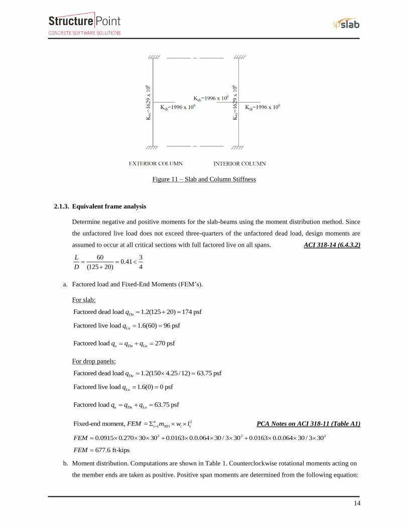
Figure 11 – Slab and Column Stiffness
2.1.3. Equivalent frame analysis
Determine negative and positive moments for the slab-beams using the moment distribution method. Since
the unfactored live load does not exceed three-quarters of the unfactored dead load, design moments are
assumed to occur at all critical sections with full factored live on all spans. ACI 318-14 (6.4.3.2)
60 30.41
(125 20) 4
L
D
a. Factored load and Fixed-End Moments (FEM’s).
For slab:
Factored dead load 1.2(125 20) 174 psfDuq
Factored live load 1.6(60) 96 psfLuq
Factored load 270 psfu Du Luq q q
For drop panels:
Factored dead load 1.2(150 4.25 /12) 63.75 psfDuq
Factored live load 1.6(0) 0 psfLuq
Factored load 63.75 psfu Du Luq q q
2
1 1Fixed-end moment, = n
i NFi iFEM m w l PCA Notes on ACI 318-11 (Table A1)
2 2 20.0915 0.270 30 30 0.0163 0.0.064 30 / 3 30 0.0163 0.0.064 30 / 3 30FEM
677.6 ft-kipsFEM
b. Moment distribution. Computations are shown in Table 1. Counterclockwise rotational moments acting on
the member ends are taken as positive. Positive span moments are determined from the following equation:

15
,
( )
2
uL uR
u midspan o
M MM M
Where Mo is the moment at the midspan for a simple beam.
When the end moments are not equal, the maximum moment in the span does not occur at the midspan, but
its value is close to that midspan for this example.
Positive moment in span 1-2:
230 (0.064 30 / 6) 30 / 6 (331.7 807.6)
(0.270 30) 2 30 / 6 30 30 / 28 2 30 2
uM
349.6 ft-kipsuM
Table 1 - Moment Distribution for Equivalent Frame
Joint 1 2 3 4
Member
DF 0.551 0.355 0.355 0.355 0.355 0.551
COF 0.578 0.578 0.578 0.578 0.578 0.578
FEM 677.6 -677.6 677.6 -677.6 677.6 -677.6
Dist -373.1 0.0 0.0 0.0 0.0 373.1
CO 0.0 -215.7 0.0 0.0 215.7 0.0
Dist 0.0 76.6 76.6 -76.6 -76.6 0.0
CO 44.3 0.0 -44.3 44.3 0.0 -44.3
Dist -24.4 15.7 15.7 -15.7 -15.7 24.4
CO 9.1 -14.1 -9.1 9.1 14.1 -9.1
Dist -5.0 8.2 8.2 -8.2 -8.2 5.0
CO 4.8 -2.9 -4.8 4.8 2.9 -4.8
Dist -2.6 2.7 2.7 -2.7 -2.7 2.6
CO 1.6 -1.5 -1.6 1.6 1.5 -1.6
Dist -0.9 1.1 1.1 -1.1 -1.1 0.9
CO 0.6 -0.5 -0.6 0.6 0.5 -0.6
Dist -0.4 0.4 0.4 -0.4 -0.4 0.4
CO 0.2 -0.2 -0.2 0.2 0.2 -0.2
Dist -0.1 0.2 0.2 -0.2 -0.2 0.1
CO 0.1 -0.1 -0.1 0.1 0.1 -0.1
Dist -0.1 0.1 0.1 -0.1 -0.1 0.1
CO 0.0 0.0 0.0 0.0 0.0 0.0
Dist 0.0 0.0 0.0 0.0 0.0 0.0
M, k-ft 331.7 -807.6 721.9 -721.9 807.6 -331.7
Midspan M,
ft-kips 349.6 197.4 349.6

16
2.1.4. Factored moments used for Design
Positive and negative factored moments for the slab system in the direction of analysis are plotted in Figure
12. The negative moments used for design are taken at the faces of supports (rectangle section or equivalent
rectangle for circular or polygon sections) but not at distances greater than 0.175 l1 from the centers of
supports. ACI 318-14 (8.11.6.1)
20 in.0.83 ft 0.175 30 5.25 ft (use face of supporting location)
12 2

17
Figure 12 - Positive and Negative Design Moments for Slab-Beam (All Spans Loaded with Full Factored Live Load)

18
2.1.5. Factored moments in slab-beam strip
a. Check whether the moments calculated above can take advantage of the reduction permitted by ACI 318-
14 (8.11.6.5):
If the slab system analyzed using EFM within the limitations of ACI 318-14 (8.10.2), it is permitted by the
ACI code to reduce the calculated moments obtained from EFM in such proportion that the absolute sum of
the positive and average negative design moments need not exceed the total static moment Mo given by
Equation 8.10.3.2 in the ACI 318-14.
Check Applicability of Direct Design Method:
1. There is a minimum of three continuous spans in each direction. ACI 318-14 (8.10.2.1)
2. Successive span lengths are equal. ACI 318-14 (8.10.2.2)
3. Long-to-Short ratio is 30/30 = 1.0 < 2.0. ACI 318-14 (8.10.2.3)
4. Column are not offset. ACI 318-14 (8.10.2.4)
5. Loads are gravity and uniformly distributed with service live-to-dead ratio of 0.41 < 2.0
(Note: The self-weight of the drop panels is not uniformly distributed entirely along the span. However,
the variation in load magnitude is small).
ACI 318-14 (8.10.2.5 and 6)
6. Check relative stiffness for slab panel. ACI 318-14 (8.10.2.7)
Slab system is without beams and this requirement is not applicable.
All limitation of ACI 318-14 (8.10.2) are satisfied and the provisions of ACI 318-14 (8.11.6.5) may be
applied:
2 22 (30 20 /12)
0.270 30 812.8 ft-kips8 8
u no
qM
ACI 318-14 (Eq. 8.10.3.2)
331.7 807.6End spans: 349.6 919.3 ft-kips
2
721.9 721.9Interior span: 197.3 919.2ft-kips
2
To illustrate proper procedure, the interior span factored moments may be reduced as follows:
Permissible reduction = 812.8/919.3 = 0.884
Adjusted negative design moment = 721.9 × 0.884 = 638.2 ft-kips
Adjusted positive design moment = 197.3 × 0.884 = 174.4 ft-kips
638.2 638.2174.4 812.8 ft-kips
2oM

19
ACI 318 allows the reduction of the moment values based on the previous procedure. Since the drop panels
may cause gravity loads not to be uniform (Check limitation #5 and Figure 12), the moment values obtained
from EFM will be used for comparison reasons.
b. Distribute factored moments to column and middle strips:
After the negative and positive moments have been determined for the slab-beam strip, the ACI code permits
the distribution of the moments at critical sections to the column strips, beams (if any), and middle strips in
accordance with the DDM. ACI 318-14 (8.11.6.6)
Distribution of factored moments at critical sections is summarized in Table 2.
Table 2 - Distribution of factored moments
Slab-beam Strip Column Strip Middle Strip
Moment
(ft-kips) Percent
Moment
(ft-kips) Percent
Moment
(ft-kips)
End Span
Exterior Negative 246.5 100 246.5 0 0.0
Positive 349.6 60 209.8 40 139.8
Interior Negative 695.9 75 521.9 25 174.0
Interior Span Negative 623.4 75 467.6 25 155.9
Positive 197.3 60 118.4 40 78.9
2.1.6. Flexural reinforcement requirements
a. Determine flexural reinforcement required for strip moments
The flexural reinforcement calculation for the column strip of end span – exterior negative location is
provided below.
246.5 ft-kipsuM
Use davg = 12.75 in.
To determine the area of steel, assumptions have to be made whether the section is tension or compression
controlled, and regarding the distance between the resultant compression and tension forces along the slab
section (jd). In this example, tension-controlled section will be assumed so the reduction factor is equal to
0.9, and jd will be taken equal to 0.95d. The assumptions will be verified once the area of steel in finalized.
Assume 0.95 12.11 in.jd d
Column strip width, 30 12 / 2 180 in.b
Middle strip width, 30 12 180 180 in.b
2246.5 120004.52 in.
0.9 60000 12.11
u
s
y
MA
f jd
2 5.09 60000Recalculate ' ' for the actual 4.52 in. 0.355 in.
0.85 ' 0.85 5000 180
s y
s
c
A fa A a
f b

20
1
0.3550.417 in.
0.85
ac
0.003 0.003( ) 0.003 ( ) 12.75 0.003 0.089 0.005
0.417t td
c
Therefore, the assumption that section is tension-controlled is valid.
2246.5 120004.357 in.
( / 2) 0.9 60000 (12.75 0.355 / 2)
u
s
y
MA
f d a
The slab have two thicknesses in the column strip (14.25 in. for the slab with the drop panel and 10 in. for
the slab without the drop panel).
14.25 30 / 3 10 30 / 2 30 / 3The weighted slab thickness, 12.83 in.
30 / 3 30 / 2 30 / 3wh
2 2
,min 0.0018 180 12.83 4.157 in. < 4.357 in.sA ACI 318-14 (24.4.3.2)
max 2 2 12.83 25.66 in. > 18 in.ws h ACI 318-14 (8.7.2.2)
max 18 in.s
Provide 10 - #6 bars with As = 4.40 in.2 and s = 180/10 = 18 in. ≤ smax
Based on the procedure outlined above, values for all span locations are given in Table 3.
Table 3 - Required Slab Reinforcement for Flexure [Equivalent Frame Method (EFM)]
Span Location Mu
(ft-kips)
b
(in.)
d
(in.)
As Req’d for
flexure (in.2)
Min As
(in.2)
Reinforcement
Provided
As Prov. for
flexure (in.2)
End Span
Column
Strip
Exterior Negative 246.5 180 12.75 4.357 4.157 10-#6 4.40
Positive 209.8 180 8.50 5.631 3.240 13-#6 5.72
Interior Negative 521.9 180 12.75 9.366 4.157 22-#6 9.68
Middle
Strip
Exterior Negative 0.0 180 8.50 0.0 3.240 10-#6 * ** 4.40
Positive 139.8 180 8.50 3.719 3.240 10-#6 ** 4.40
Interior Negative 174.0 180 8.50 4.649 3.240 11-#6 4.84
Interior Span
Column
Strip Positive 118.4 180 8.50 3.141 3.240 10-#6 * ** 4.40
Middle
Strip Positive 78.9 180 8.50 2.083 3.240 10-#6 * ** 4.40
* Design governed by minimum reinforcement. ** Number of bars governed by maximum allowable spacing.
b. Calculate additional slab reinforcement at columns for moment transfer between slab and column by
flexure
The factored slab moment resisted by the column (γf x Msc) shall be assumed to be transferred by flexure.
Concentration of reinforcement over the column by closer spacing or additional reinforcement shall be used

21
to resist this moment. The fraction of slab moment not calculated to be resisted by flexure shall be assumed
to be resisted by eccentricity of shear. ACI 318-14 (8.4.2.3)
Portion of the unbalanced moment transferred by flexure is γf x Msc ACI 318-14 (8.4.2.3.1)
Where
1 2
1
1 (2 / 3) /f b b
ACI 318-14 (8.4.2.3.2)
b1 = Dimension of the critical section bo measured in the direction of the span for which moments are
determined in ACI 318, Chapter 8 (see Figure 13).
b2 = Dimension of the critical section ob measured in the direction perpendicular to 1b in ACI 318, Chapter
8 (see Figure 13).
bb = Effective slab width = 2c 3 h ACI 318-14 (8.4.2.3.3)
Figure 13 – Critical Shear Perimeters for Columns
For exterior support:
d = h – cover – d/2 = 14.25 – 0.75 – 0.75/2 = 13.13 in.
1b c1 + d/2 = 20 + 13.13/2 = 26.56 in.
2b c2 + d = 20 + 13.13 = 33.13 in.
20 3 14.25 62.75bb in.

22
1
0.6261 (2 / 3) 26.56 / 33.13f
0.626 331.7 207.7 ft-kipsf sc
M
Using the same procedure in 2.1.7.a, the required area of steel:
23.63 in.sA
However, the area of steel provided to resist the flexural moment within the effective slab width bb:
2
,
62.75 4.40 1.534 in.
180s providedA
Then, the required additional reinforcement at exterior column for moment transfer between slab and
column:
2
, 3.63-1.534 2.096 in.s additionalA
Provide 5 - #6 additional bars with As = 2.20 in.2
Based on the procedure outlined above, values for all supports are given in Table 4.
Table 4 - Additional Slab Reinforcement required for moment transfer between slab and column (EFM)
Span Location Msc
*
(ft-kips) γf
γf Msc
(ft-kips)
Effective slab
width, bb
(in.)
d
(in.)
As req’d
within bb
(in.2)
As prov. For
flexure within bb
(in.2)
Add’l
Reinf.
End Span
Column Strip Exterior Negative 331.7 0.626 207.7 62.75 13.13 3.63 1.534 5-#6
Interior Negative 85.7 0.60 51.42 62.75 13.13 0.877 3.375 -
*Msc is taken at the centerline of the support in Equivalent Frame Method solution.
2.1.7. Factored moments in columns
The unbalanced moment from the slab-beams at the supports of the equivalent frame are distributed to the
support columns above and below the slab-beam in proportion to the relative stiffness of the support columns.
Referring to Figure 12, the unbalanced moment at the exterior and interior joints are:
Exterior Joint = +331.7 ft-kips
Joint 2= -807.6 + 721.9 = -85.7 ft-kips
The stiffness and carry-over factors of the actual columns and the distribution of the unbalanced slab
moments (Msc) to the exterior and interior columns are shown in Figure 14.

23
Figure 14 - Column Moments (Unbalanced Moments from Slab-Beam)
In summary:
For Top column: For Bottom column:
Mcol,Exterior= 150.61 ft-kips Mcol,Exterior= 157.21 ft-kips
Mcol,Interior = 38.91 ft-kips Mcol,Interior = 40.62 ft-kips
The moments determined above are combined with the factored axial loads (for each story) and factored
moments in the transverse direction for design of column sections. The moment values at the face of interior,
exterior, and corner columns from the unbalanced moment values are shown in the following table.
Table 5 – Factored Moments in Columns
Mu
kips-ft
Column Location
Interior Exterior Corner
Mux 40.62 157.21 157.21
Muy 40.62 40.62 157.21

24
3. Design of Columns by spColumn
This section includes the design of interior, edge, and corner columns using spColumn software. The preliminary
dimensions for these columns were calculated previously in section one. The reduction of live load per ASCE
7-10 will be ignored in this example. However, the detailed procedure to calculate the reduced live loads is
explained in the “wide-Module Joist System” example.
3.1. Determination of factored loads
Interior Column:
Assume 5 story building
Tributary area for interior column for live load, superimposed dead load, and self-weight of the slab is
230 30 900 ftTributaryA
Tributary area for interior column for self-weight of additional slab thickness due to the presence of the drop
panel is
210 10 100 ftTributaryA
Assuming five story building
5 0.270 900 0.0638 100 1247 kipsu u TributaryP n q A
Mu,x = 40.62 ft-kips (see the previous Table)
Mu,y = 40.62 ft-kips (see the previous Table)
Edge (Exterior) Column:
Tributary area for interior column for live load, superimposed dead load, and self-weight of the slab is
230 20 / 230 475 ft
2 12TributaryA
Tributary area for interior column for self-weight of additional slab thickness due to the presence of the
drop panel is
210 20 / 210 58.33 ft
2 12TributaryA
5 0.270 475 0.0638 58.33 660 kipsu u TributaryP n q A
Mu,x = 157.21 ft-kips (see the previous Table)
Mu,y = 40.62 ft-kips (see the previous Table)
Corner Column:
Tributary area for interior column for live load, superimposed dead load, and self-weight of the slab is

25
230 20 / 2 30 20 / 2251 ft
2 12 2 12TributaryA
Tributary area for interior column for self-weight of additional slab thickness due to the presence of the
drop panel is
210 20 / 2 10 20 / 234.03 ft
2 12 2 12TributaryA
5 0.270 251 0.0638 34.03 350 kipsu u TributaryP n q A
Mu,x = 157.21 ft-kips (see the previous Table)
Mu,y = 157.21 ft-kips (see the previous Table)

26
3.2. Moment Interaction Diagram
Interior Column:

27
Edge Column:

28
Corner Column:

29
4. Shear Strength
Shear strength of the slab in the vicinity of columns/supports includes an evaluation of one-way shear (beam
action) and two-way shear (punching) in accordance with ACI 318 Chapter 22.
4.1. One-Way (Beam action) Shear Strength
ACI 318-14 (22.5)
One-way shear is critical at a distance d from the face of the column as shown in Figure 3. Figures 15 and 16
show the factored shear forces (Vu) at the critical sections around each column and each drop panel,
respectively. In members without shear reinforcement, the design shear capacity of the section equals to the
design shear capacity of the concrete:
, ( 0)n c s c sφV φV φV φV V ACI 318-14 (Eq. 22.5.1.1)
Where:
cc w
'φV φ2λ f b d ACI 318-14 (Eq. 22.5.5.1)
4.1.1. At distance d from the supporting column
14.25 30 / 6 10 30 30 / 611.42 in.
30weightedh
11.42 0.75 0.75 / 2 10.29 in.wd
1for normal weight concrete
50000.75 2 1.0 (30 12) 10.29 392.91 kips
1000cV
Because at all the critical sections, the slab has adequate one-way shear strength.c uV V
Figure 15 – One-way shear at critical sections (at distance d from the face of the supporting column)

30
4.1.2. At the face of the drop panel
10 in.h in.
10 0.75 0.75 / 2 8.88 in.d
1for normal weight concrete
50000.75 2 1.0 (30 12) 8.88 339.1 kips
1000cV
Because at all the critical sections, the slab has adequate one-way shear strength.c uV V
Figure 16 – One-way shear at critical sections (at the face of the drop panel)

31
4.2. Two-Way (Punching) Shear Strength
ACI 318-14 (22.6)
4.2.1. Around the columns faces
Two-way shear is critical on a rectangular section located at d/2 away from the face of the column as shown
in Figure 13.
a. Exterior column:
The factored shear force (Vu) in the critical section is computed as the reaction at the centroid of the critical
section minus the self-weight and any superimposed surface dead and live load acting within the critical section
(d/2 away from column face).
26.56 33.13105.64 0.334 103.60 kips
144u
u 1 2V V q b b
The factored unbalanced moment used for shear transfer, Munb, is computed as the sum of the joint moments
to the left and right. Moment of the vertical reaction with respect to the centroid of the critical section is also
taken into account.
1
26.56 8.18 20 / 2/ 2 331.7 103.60 259 ft-kips
12unb u 1 AB
M M V b c c
For the exterior column in Figure 13, the location of the centroidal axis z-z is:
2(26.56 13.13 26.56 / 2)8.18 in.
2 26.56 13.13 33.13 13.13AB
moment of area of the sides about ABc
area of the sides
The polar moment Jc of the shear perimeter is:
23 3
21 1 121
2 12 12 2
ABc AB
b d db bJ b d c b dc
23 3
226.56 13.13 13.13 26.56 26.562 26.56 13.13 8.18 33.13 13.13 8.18
12 12 2cJ
498,315 in.c
J
1 1 0.626 0.374 v f
γ γ ACI 318-14 (Eq. 8.4.4.2.2)
The length of the critical perimeter for the exterior column:
2 26.56 33.13 86.26 in.ob
The two-way shear stress (vu) can then be calculated as:

32
u v unb ABu
o c
V γ M cv
b d J
ACI 318-14 (R.8.4.4.2.3)
103.60 1000 0.374 (259 12 1000) 8.18188.3 psi
86.26 13.13 98,315uv
44 , 2 , 2' ' 's
c c c co
α dv min λ f λ f λ f
β b
ACI 318-14 (Table 22.6.5.2)
4 30 13.134 1 5000 , 2 1 5000 , 2 1 5000
1 86.26cv min
282.8 , 424.3 , 464.3 282.8 psicv min psi
0.75 282.8 212.1psicφ v
Since at the critical section, the slab has adequate two-way shear strength at this joint.c uφ v v
b. Interior column:
33.13 33.13137.36 121.5 0.334 256.35 kips
144u
u 1 2V V q b b
1
/ 2 807.6 721.9 256.31 0 85.70 ft-kipsunb u 1 ABM M V b c c
For the interior column in Figure 13, the location of the centroidal axis z-z is:
1 33.1316.57in.
2 2AB
bc
The polar moment Jc of the shear perimeter is:
23 3
21 1 121
2 212 12 2
ABc AB
b d db bJ b d c b dc
23 3
233.13 13.13 13.13 33.13 33.132 33.13 13.13 16.57 2 33.13 13.13 16.57
12 12 2cJ
4330,800 in.c
J
1 1 0.600 0.400 v f
γ γ ACI 318-14 (Eq. 8.4.4.2.2)
The length of the critical perimeter for the interior column:

33
2 33.13 33.13 132.52 in.ob
The two-way shear stress (vu) can then be calculated as:
u v unb ABu
o c
V γ M cv
b d J
ACI 318-14 (R.8.4.4.2.3)
256.31 1000 0.400 (85.70 12 1000) 16.57167.9 psi
132.52 13.13 330,800uv
4 4 , 2 , 2' ' 's
c c c co
α dv min λ f λ f λ f
β b
ACI 318-14 (Table 22.6.5.2)
4 40 13.134 1 5000 , 2 1 5000 , 2 1 5000
1 132.52cv min
282.8 , 424.3 , 421.7 psi 282.8 psicv min
0.75 282.8 212.1psicφ v
Since at the critical section, the slab has adequate two-way shear strength at this joint.c uφ v v
c. Corner column:
In this example, interior equivalent frame strip was selected where it only have exterior and interior supports
(no corner supports are included in this strip). However, the two-way shear strength of corner supports usually
governs. Thus, the two-way shear strength for the corner column in this example will be checked for educational
purposes. Same procedure is used to find the reaction and factored unbalanced moment used for shear transfer
at the centroid of the critical section for the corner support for the exterior equivalent frame strip.
26.56 26.56
61.93 0.334 60.29 kips144
u u 1 2V V q b b
1
26.56 6.64 20 / 2/ 2 189.12 60.29 139.26 ft-kips
12unb u 1 ABM M V b c c
For the interior column in Figure 13, the location of the centroidal axis z-z is:
(26.56 13.13 26.56 / 2)6.64 in.
26.56 13.13 26.56 13.13AB
moment of area of the sides about ABc
area of the sides
in.
The polar moment Jc of the shear perimeter is:
3
21 1 11 2
23
12 12 2
c AB AB
b d db bJ b d c b dc

34
23 3
226.56 13.13 13.13 26.56 26.5626.56 13.13 6.64 26.56 13.13 6.64
12 12 2cJ
456,292 in.cJ
1 1 0.600 0.400v f
γ γ ACI 318-14 (Eq. 8.4.4.2.2)
The length of the critical perimeter for the corner column:
26.56 26.56 53.13 in.ob
The two-way shear stress (vu) can then be calculated as:
u v unb ABu
o c
V γ M cv
b d J
ACI 318-14 (R.8.4.4.2.3)
60.29 1000 0.400 (139.26 12 1000) 6.64165.3 psi
53.13 13.13 56,292uv
44 , 2 , 2' ' 's
c c c co
α dv min λ f λ f λ f
β b
ACI 318-14 (Table 22.6.5.2)
4 20 13.134 1 5000 , 2 1 5000 , 2 1 5000
1 53.13cv min
282.8 , 424.3 , 490.9 psi 282.8 psicv min
0.75 282.8 212.1 psicφ v
Since at the critical section, the slab has adequate two-way shear strength at this joint.c uφ v v
4.2.2. Around drop panels
Two-way shear is critical on a rectangular section located at d/2 away from the face of the drop panel.
a. Exterior drop panel:
70 120 74.44 128.88 70 120105.64 0.334 0.270 83.92 kips
144 144u
u1 1 u2 2V V q A q A
1
74.44 19.95 20 / 2/ 2 331.7 83.92 20.57 ft-kips
12unb u 1 AB
M M V b c c
For the exterior drop panel, the location of the centroidal axis z-z is:

35
2(74.44 8.88 74.44 / 2)19.95 in.
2 74.44 8.88 128.88 8.88AB
moment of area of the sides about ABc
area of the sides
The polar moment Jc of the shear perimeter is:
23 3
21 1 121
2 12 12 2
ABc AB
b d db bJ b d c b dc
23 3
274.44 8.88 8.88 74.44 74.442 74.44 8.88 19.95 128.88 8.88 19.95
12 12 2cJ
41,468,983 in.c
J
1 1 0.664 0.336 v f
γ γ ACI 318-14 (Eq. 8.4.4.2.2)
The length of the critical perimeter for the exterior drop panel:
2 74.44 128.88 277.76 in.ob
The two-way shear stress (vu) can then be calculated as:
u v unb ABu
o c
V γ M cv
b d J
ACI 318-14 (R.8.4.4.2.3)
83.92 1000 0.336 (20.57 12 1000) 19.9535.2 psi
277.76 8.88 1,468,983uv
44 , 2 , 2' ' 's
c c c co
α dv min λ f λ f λ f
β b
ACI 318-14 (Table 22.6.5.2)
4 30 8.884 1 5000 , 2 1 5000 , 2 1 5000
1 277.76cv min
282.8 , 424.3 , 209.2 psi 209.2 psicv min
0.75 209.2 156.9 psicφ v
Since at the critical section, the slab has adequate two-way shear strength around this drop panel.c uφ v v
36
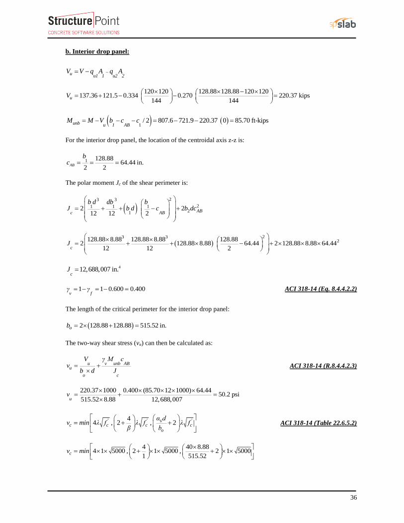
b. Interior drop panel:
uu1 1 u2 2
V V q A q A
120 120 128.88 128.88 120 120137.36 121.5 0.334 0.270 220.37 kips
144 144uV
1
/ 2 807.6 721.9 220.37 0 85.70 ft-kipsunb u 1 ABM M V b c c
For the interior drop panel, the location of the centroidal axis z-z is:
1 128.8864.44 in.
2 2AB
bc
The polar moment Jc of the shear perimeter is:
23 3
21 1 121
2 212 12 2
ABc AB
b d db bJ b d c b dc
23 3
2128.88 8.88 128.88 8.88 128.882 128.88 8.88 64.44 2 128.88 8.88 64.44
12 12 2cJ
412,688,007 in.c
J
1 1 0.600 0.400 v f
γ γ ACI 318-14 (Eq. 8.4.4.2.2)
The length of the critical perimeter for the interior drop panel:
2 128.88 128.88 515.52 in.ob
The two-way shear stress (vu) can then be calculated as:
u v unb ABu
o c
V γ M cv
b d J
ACI 318-14 (R.8.4.4.2.3)
220.37 1000 0.400 (85.70 12 1000) 64.4450.2 psi
515.52 8.88 12,688,007uv
44 , 2 , 2' ' 's
c c c co
α dv min λ f λ f λ f
β b
ACI 318-14 (Table 22.6.5.2)
4 40 8.884 1 5000 , 2 1 5000 , 2 1 5000
1 515.52cv min
37
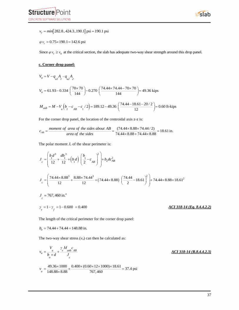
282.8 , 424.3 , 190.1 psi 190.1 psicv min
0.75 190.1 142.6 psicφ v
Since at the critical section, the slab has adequate two-way shear strength around this drop panel.c uφ v v
c. Corner drop panel:
uu1 1 u2 2
V V q A q A
70 70 74.44 74.44 70 7061.93 0.334 0.270 49.36 kips
144 144uV
1
74.44 18.61 20 / 2/ 2 189.12 49.36 0.60 ft-kips
12unb u 1 AB
M M V b c c
For the corner drop panel, the location of the centroidal axis z-z is:
(74.44 8.88 74.44 / 2)18.61in.
74.44 8.88 74.44 8.88AB
moment of area of the sides about ABc
area of the sides
The polar moment Jc of the shear perimeter is:
23 3
21 1 121
12 12 2
ABc AB
b d db bJ b d c b dc
23 3
274.44 8.88 8.88 74.44 74.4474.44 8.88 18.61 74.44 8.88 18.61
12 12 2cJ
4767,460 in.c
J
1 1 0.600 0.400v f
γ γ ACI 318-14 (Eq. 8.4.4.2.2)
The length of the critical perimeter for the corner drop panel:
74.44 74.44 148.88 in.ob
The two-way shear stress (vu) can then be calculated as:
u v unb ABu
o c
V γ M cv
b d J
ACI 318-14 (R.8.4.4.2.3)
49.36 1000 0.400 (0.60 12 1000) 18.6137.4 psi
148.88 8.88 767,460uv

38
44 , 2 , 2' ' 's
c c c co
α dv min λ f λ f λ f
β b
ACI 318-14 (Table 22.6.5.2)
4 20 8.884 1 5000 , 2 1 5000 , 2 1 5000
1 148.88cv min
282.8 , 424.3 ,225.8 psi 225.8 psicv min
0.75 225.8 169.3 psicφ v
Since at the critical section, the slab has adequate two-way shear strength around this drop panel.c uφ v v

39
5. Serviceability Requirements (Deflection Check)
Since the slab thickness was selected below the minimum slab thickness tables in ACI 318-14, the deflection
calculations of immediate and time-dependent deflections are required and shown below including a comparison
with spSlab model results.
5.1. Immediate (Instantaneous) Deflections
The calculation of deflections for two-way slabs is challenging even if linear elastic behavior can be assumed.
Elastic analysis for three service load levels (D, D + Lsustained, D+LFull) is used to obtain immediate deflections
of the two-way slab in this example. However, other procedures may be used if they result in predictions of
deflection in reasonable agreement with the results of comprehensive tests. ACI 318-14 (24.2.3)
The effective moment of inertia (Ie) is used to account for the cracking effect on the flexural stiffness of the
slab. Ie for uncracked section (Mcr > Ma) is equal to Ig. When the section is cracked (Mcr < Ma), then the
following equation should be used:
3 3
1 cr cre
g cr ga a
M MI I I I
M M
ACI 318-14 (Eq. 24.2.3.5a)
Where:
Ma = Maximum moment in member due to service loads at stage deflection is calculated.
The values of the maximum moments for the three service load levels are calculated from structural analysis as
shown previously in this document. These moments are shown in Figure 17.

40
Figure 17 – Maximum Moments for the Three Service Load Levels
For positive moment (midspan) section:
Cracking moment.crM
530.33 30000 1265.17 ft-kips
5 12 1000
r g
crt
f IM
y
ACI 318-14 (Eq. 24.2.3.5b)
= Modulus of rapture of concrete.rf
'7.5 7.5 1.0 5000 530.33 psir c
f f ACI 318-14 (Eq. 19.2.3.1)
= Moment of inertia of the gross uncracked concrete section.gI

41
3 3
2230 12 10
30000 in.12 12g
l hI
yt = Distance from centroidal axis of gross section, neglecting reinforcement, to tension face, in.
105 in.
2 2t
hy
= Moment of inertia of the cracked section transformed to concrete.crI PCA Notes on ACI 318-11 (9.5.2.2)
As calculated previously, the positive reinforcement for the end span frame strip is 23 #6 bars located at 1.125
in. along the section from the bottom of the slab. Two of these bars are not continuous and will be excluded
from the calculation of Icr. Figure 18 shows all the parameters needed to calculate the moment of inertia of the
cracked section transformed to concrete at midspan.
Figure 18 – Cracked Transformed Section (positive moment section)
= Modulus of elasticity of slab concrete.csE
1.5 1.5 333 150 33 5000 4287 10 psics c cE w f ACI 318-14 (19.2.2.1.a)
290000006.76
4287000
s
cs
En
E PCA Notes on ACI 318-11 (Table 10-2)
130 12
5.76 in. 6.76 21 0.44
s
bB
n A
PCA Notes on ACI 318-11 (Table 10-2)
2 1 1 2 8.88 5.76 1 11.59 in.
5.76
dBkd
B
PCA Notes on ACI 318-11 (Table 10-2)
32( )
( )3
cr s
b kdI nA d kd PCA Notes on ACI 318-11 (Table 10-2)
43
230 12 (1.59)6.76 21 0.44 8.88 1.59 3802 in.
3crI
For negative moment section (near the interior support of the end span):
The negative reinforcement for the end span frame strip near the interior support is 32 #6 bars located at 1.125
in. along the section from the top of the slab.

42
530.33 53445 1401.42 ft-kips
5.88 12 1000
r g
crt
f IM
y
ACI 318-14 (Eq. 24.2.3.5b)
'7.5 7.5 1.0 5000 530.33 psir c
f f ACI 318-14 (Eq. 19.2.3.1)
253445 in.gI
5.88 in.ty
Figure 19 – Ig calculations for slab section near support
1.5 1.5 333 150 33 5000 4287 10 psics c cE w f ACI 318-14 (19.2.2.1.a)
290000006.76
4287000
s
cs
En
E PCA Notes on ACI 318-11 (Table 10-2)
110 12
1.26 in. 6.76 32 0.44
b
s
bB
n A
PCA Notes on ACI 318-11 (Table 10-2)
2 1 1 2 13.13 1.26 1 13.84 in.
1.26
dBkd
B
PCA Notes on ACI 318-11 (Table 10-2)
3
2( )
( )3
b
cr s
b kdI nA d kd PCA Notes on ACI 318-11 (Table 10-2)
43
210 12 (3.84)6.76 32 0.44 13.13 3.84 10471in.
3crI

43
Figure 20 – Cracked Transformed Section (negative moment section)
The effective moment of inertia procedure described in the Code is considered sufficiently accurate to estimate
deflections. The effective moment of inertia, Ie, was developed to provide a transition between the upper and
lower bounds of Ig and Icr as a function of the ratio Mcr/Ma. For conventionally reinforced (nonprestressed)
members, the effective moment of inertia, Ie, shall be calculated by Eq. (24.2.3.5a) unless obtained by a more
comprehensive analysis.
Ie shall be permitted to be taken as the value obtained from Eq. (24.2.3.5a) at midspan for simple and continuous
spans, and at the support for cantilevers. ACI 318-14 (24.2.3.7)
For continuous one-way slabs and beams. Ie shall be permitted to be taken as the average of values obtained
from Eq. (24.2.3.5a) for the critical positive and negative moment sections. ACI 318-14 (24.2.3.6)
For the middle span (span with two ends continuous) with service load level (D+LLfull):
3 3
1 , since 401.4 ft-kips < =546.5 ft-kipscr acr cr
e g cra a
M MI I I M M
M M
ACI 318-14 (24.2.3.5a)
Where Ie- is the effective moment of inertia for the critical negative moment section (near the support).
4
3 3401.4 401.4
53445 1 10471 27503 in.546.5 546.5e
I
430000 in. , since 265.17 ft-kips > =152.03 ft-kipscr ae g
I I M M
Where Ie+ is the effective moment of inertia for the critical positive moment section (midspan).

44
Since midspan stiffness (including the effect of cracking) has a dominant effect on deflections, midspan section
is heavily represented in calculation of Ie and this is considered satisfactory in approximate deflection
calculations. Both the midspan stiffness (Ie+) and averaged span stiffness (Ie,avg) can be used in the calculation
of immediate (instantaneous) deflection.
The averaged effective moment of inertia (Ie,avg) is given by:
,, ,
0.70 0.15 for interior spane avge e l e r
I I I I PCA Notes on ACI 318-11 (9.5.2.4(2))
, 0.85 0.15 for end spane avge e
I I I PCA Notes on ACI 318-11 (9.5.2.4(1))
However, these expressions lead to improved results only for continuous prismatic members. The drop panels
in this example result in non-prismatic members and the following expressions should be used according to
ACI 318-89:
,, ,
0.50 0.25 for interior spane avge e l e r
I I I I ACI 435R-95 (2.14)
For the middle span (span with two ends continuous) with service load level (D+LLfull):
4
, 0.50 30000 0.25 27503 27503 41723 in.e avgI
, 0.50 0.50 for end spane avge e
I I I ACI 435R-95 (2.14)
For the end span (span with one end continuous) with service load level (D+LLfull):
4
, 0.50 26503 0.50 22649 37190 in.e avgI
Where:
,= The effective moment of inertia for the critical negative moment section near the left support.
e lI
,= The effective moment of inertia for the critical negative moment section near the right support.
e lI
= The effective moment of inertia for the critical positive moment section (midspan).e
I

45
Table 6 provides a summary of the required parameters and calculated values needed for deflections for exterior
and interior spans.
Table 6 – Averaged Effective Moment of Inertia Calculations
For Frame Strip
Span zone Ig,
in.4
Icr,
in.4
Ma, kips-ft
Mcr,
k-ft
Ie, in.4 Ie,avg, in.4
D D +
LLSus
D +
Lfull D
D +
LLSus
D +
Lfull D
D +
LLSus
D +
Lfull
Ext
Left 53445 7170 -179.72 -179.72 -252.8 401.42 53445 53445 53445
37190 37190 24576 Midspan 30000 3797 197.23 197.23 278.14 265.17 30000 30000 26503
Right 53445 10471 -434.41 -434.41 -611.14 401.42 44379 44379 22649
Int
Left 53445 10471 -388.46 -388.46 -546.48 401.42 53445 53445 27503
41723 41723 28752 Mid 30000 3317 107.56 107.56 152.03 265.17 30000 30000 30000
Right 53445 10471 -388.46 -388.46 -546.48 401.42 53445 53445 27503
Deflections in two-way slab systems shall be calculated taking into account size and shape of the panel,
conditions of support, and nature of restraints at the panel edges. For immediate deflections in two-way slab
systems, the midpanel deflection is computed as the sum of deflection at midspan of the column strip or column
line in one direction (Δcx or Δcy) and deflection at midspan of the middle strip in the orthogonal direction (Δmx
or Δmy). Figure 21 shows the deflection computation for a rectangular panel. The average Δ for panels that have
different properties in the two direction is calculated as follows:
( ) ( )
2
cx my cy mx
PCA Notes on ACI 318-11 (9.5.3.4 Eq. 8)

46
Figure 21 – Deflection Computation for a rectangular Panel
To calculate each term of the previous equation, the following procedure should be used. Figure 22 shows the
procedure of calculating the term Δcx. Same procedure can be used to find the other terms.
Figure 22 –Δcx calculation procedure

47
For end span - service dead load case:
4
,
,384
frame fixed
c frame averaged
wl
E I PCA Notes on ACI 318-11 (9.5.3.4 Eq. 10)
Where:
, = Deflection of column strip assuing fixed end condition.frame fixed
(20 150 10 /12)(30) 4350 lb/ftw
1.5 333 4287 10 psic c cE w f ACI 318-14 (19.2.2.1.a)
Iframe,averaged = The averaged effective moment of inertia (Ie,avg) for the frame strip for service dead load case
from Table 6 = 37190 in.4
4 3
,3
(4350)(30) (12)0.0995 in.
384(4287 10 )(37190)frame fixed
,
, ,
,
frame averaged
c fixed c frame fixed
c g
ILDF
I PCA Notes on ACI 318-11 (9.5.3.4 Eq. 11)
For this example and like in the spSlab program, the effective moment of inertia at midspan will be used.
LDFc is the load distribution factor for the column strip. The load distribution factor for the column strip can
be found from the following equation:
2
2
l R
c
LDF LDFLDF
LDF
And the load distribution factor for the middle strip can be found from the following equation:
1m c
LDF LDF
For the end span, LDF for exterior negative region (LDFL¯), interior negative region (LDFR¯), and positive
region (LDFL+
) are 1.00, 0.75, and 0.60, respectively (From Table 2 of this document). Thus, the load
distribution factor for the column strip for the end span is given by:

48
1.0 0.750.6
2 0.7382c
LDF
Ic,g = The gross moment of inertia (Ig) for the column strip for service dead load = 15000 in.4
,
300000.738 0.0995 0.1468 in.
15000c fixed
,
,
( )net L frame
c L
ec
M
K PCA Notes on ACI 318-11 (9.5.3.4 Eq. 12)
Where:
, = Rotation of the span left support.c L
,( ) 179.72 ft-kips = Net frame strip negative moment of the left support.net L frameM
Kec = effective column stiffness = 61353 10 in.-lb (calculated previously).
,6
179.72 12 10000.00159 rad
1353 10c L
, , 8
frame
g
c L c L
e
Il
I
PCA Notes on ACI 318-11 (9.5.3.4 Eq. 14)
Where:
, = Midspan deflection due to rotation of left support.c L
= Gross-to-effective moment of inertia ratio for frame strip.g
e frame
I
I
,
30 12 300000.00159 0.05786 in.
8 37190c L

49
,
,
( )(611.14 546.48) 12 1000
0.00041 rad61353 10
net R frame
c R
ec
M
K
Where
, = Rotation of the end span right support.c R
,( ) Net frame strip negative moment of the right support.net R frameM
, ,
30 12 300000.00041 0.01479 in.
8 8 37190
g
c R c R
e frame
Il
I
Where:
, = Midspan delfection due to rotation of right support.c R
, ,,cx cx R cx Lcx fixed PCA Notes on ACI 318-11 (9.5.3.4 Eq. 9)
0.1468 0.01479 0.05786 0.219 in.cx
Following the same procedure, Δmx can be calculated for the middle strip. This procedure is repeated for the
equivalent frame in the orthogonal direction to obtain Δcy, and Δmy for the end and middle spans for the other
load levels (D+LLsus and D+LLfull).
Since in this example the panel is squared, Δcx = Δcy= 0.219 in. and Δmx = Δmy= 0.125 in.
The average Δ for the corner panel is calculated as follows:
( ) ( )
0.219 0.125 0.344 in.2
cx my cy mxcx my cy mx

59
Table 7 – Immediate (Instantaneous) Deflections in the x-direction
Column Strip
Middle Strip
Span LDF
D
LDF
D
Δframe-fixed,
in.
Δc-fixed,
in.
θc1,
rad
θc2,
rad
Δθc1,
in.
Δθc2,
in.
Δcx,
in.
Δframe-fixed,
in.
Δm-fixed,
in.
θm1,
rad
θm2,
rad
Δθm1,
in.
Δθm2,
in.
Δmx,
in.
Ext 0.738 0.0995 0.1468 0.00159 0.00041 0.05786 0.01479 0.219
0.262 0.0995 0.0521 0.00159 0.00041 0.05786 0.01479 0.125
Int 0.675 0.0886 0.1197 0.00041 0.00041 -0.01319 -0.01319 0.093
0.325 0.0886 0.0576 0.00041 0.00041 -0.01319 -0.01319 0.031
Span LDF
D+LLsus
LDF
D+LLsus
Δframe-fixed,
in.
Δc-fixed,
in.
θc1,
rad
θc2,
rad
Δθc1,
in.
Δθc2,
in.
Δcx,
in.
Δframe-fixed,
in.
Δm-fixed,
in.
θm1,
rad
θm2,
rad
Δθm1,
in.
Δθm2,
in.
Δmx,
in.
Ext 0.738 0.0995 0.1468 0.00159 0.00041 0.05786 0.01479 0.219
0.262 0.0995 0.0521 0.00159 0.00041 0.05786 0.01479 0.125
Int 0.675 0.0886 0.1197 0.00041 0.00041 -0.01319 -0.01319 0.093
0.325 0.0886 0.0576 0.00041 0.00041 -0.01319 -0.01319 0.031
Span LDF
D+LLfull
LDF
D+LLfull
Δframe-fixed,
in.
Δc-fixed,
in.
θc1,
rad
θc2,
rad
Δθc1,
in.
Δθc2,
in.
Δcx,
in.
Δframe-fixed,
in.
Δm-fixed,
in.
θm1,
rad
θm2,
rad
Δθm1,
in.
Δθm2,
in.
Δmx,
in.
Ext 0.738 0.2128 0.2775 0.00224 0.00057 0.12316 0.0315 0.432
0.262 0.2128 0.0985 0.00224 0.00057 0.12316 0.03125 0.253
Int 0.675 0.1819 0.2455 0.00057 0.00057 -0.02693 -0.02693 0.192
0.325 0.1819 0.1182 0.00057 0.00057 -0.02693 -0.02693 0.064
Span LDF
LL
LDF
LL
Δcx,
in. Δmx,
in. Ext 0.738 0.213
0.262 0.128
Int 0.675 0.098
0.325 0.033

60
5.2. Time-Dependent (Long-Term) Deflections (Δlt)
The additional time-dependent (long-term) deflection resulting from creep and shrinkage (Δcs) may be estimated
as follows:
( )cs sust Inst PCA Notes on ACI 318-11 (9.5.2.5 Eq. 4)
The total time-dependent (long-term) deflection is calculated as:
( ) ( ) (1 ) [( ) ( ) ]sust Inst total Inst sust Insttotal lt CSA A23.3-04 (N9.8.2.5)
Where:
( ) Immediate (instantaneous) deflection due to sustained load, in.sust Inst
1 50 '
ACI 318-14 (24.2.4.1.1)
( ) Time-dependent (long-term) total delfection, in.total lt
( ) Total immediate (instantaneous) deflection, in.total Inst
For the exterior span
= 2, consider the sustained load duration to be 60 months or more. ACI 318-14 (Table 24.2.4.1.3)
' = 0, conservatively.
22
1 50 0
2 0.219 0.439 in.cs
0.219 1 2 0.432 0.219 0.871 in.total lt
61
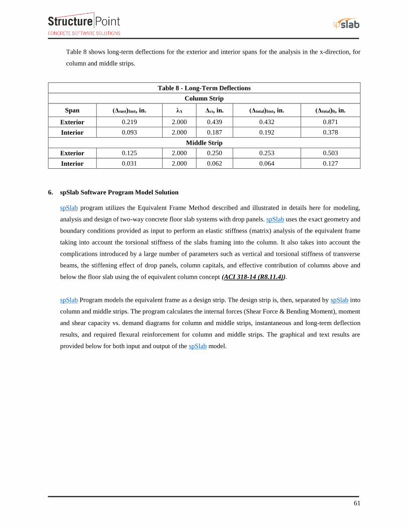
Table 8 shows long-term deflections for the exterior and interior spans for the analysis in the x-direction, for
column and middle strips.
Table 8 - Long-Term Deflections
Column Strip
Span (Δsust)Inst, in. λΔ Δcs, in. (Δtotal)Inst, in. (Δtotal)lt, in.
Exterior 0.219 2.000 0.439 0.432 0.871
Interior 0.093 2.000 0.187 0.192 0.378
Middle Strip
Exterior 0.125 2.000 0.250 0.253 0.503
Interior 0.031 2.000 0.062 0.064 0.127
6. spSlab Software Program Model Solution
spSlab program utilizes the Equivalent Frame Method described and illustrated in details here for modeling,
analysis and design of two-way concrete floor slab systems with drop panels. spSlab uses the exact geometry and
boundary conditions provided as input to perform an elastic stiffness (matrix) analysis of the equivalent frame
taking into account the torsional stiffness of the slabs framing into the column. It also takes into account the
complications introduced by a large number of parameters such as vertical and torsional stiffness of transverse
beams, the stiffening effect of drop panels, column capitals, and effective contribution of columns above and
below the floor slab using the of equivalent column concept (ACI 318-14 (R8.11.4)).
spSlab Program models the equivalent frame as a design strip. The design strip is, then, separated by spSlab into
column and middle strips. The program calculates the internal forces (Shear Force & Bending Moment), moment
and shear capacity vs. demand diagrams for column and middle strips, instantaneous and long-term deflection
results, and required flexural reinforcement for column and middle strips. The graphical and text results are
provided below for both input and output of the spSlab model.

X
YZ
spSlab v5.00. Licensed to: StructurePoint. License ID: 66184-1055152-4-2C6B6-2C6B6
File: C:\TSDA\TSDA-spSlab-Two-Way Slab with Drop Panels.slb
Project: Two-Way Slab with Drop Panels
Frame: Interior Frame
Engineer: SP
Code: ACI 318-14
Date: 03/16/17
Time: 15:42:36

spSlab v5.00. Licensed to: StructurePoint. License ID: 66184-1055152-4-2C6B6-2C6B6
File: C:\TSDA\TSDA-spSlab-Two-Way Slab with Drop Panels.slb
Project: Two-Way Slab with Drop Panels
Frame: Interior Frame
Engineer: SP
Code: ACI 318-14
Date: 03/16/17
Time: 15:44:15
CASE: SELF
CASE: Dead
CASE/PATTERN: Live/All
125 lb/ft2 125 lb/ft2 125 lb/ft2 125 lb/ft2 125 lb/ft2
20 lb/ft2 20 lb/ft2 20 lb/ft220 lb/ft2 20 lb/ft2
60 lb/ft260 lb/ft2 60 lb/ft2 60 lb/ft2 60 lb/ft2
531.25 lb/ft531.25 lb/ft 531.25 lb/ft531.25 lb/ft 531.25 lb/ft531.25 lb/ft 531.25 lb/ft531.25 lb/ft

spSlab v5.00. Licensed to: StructurePoint. License ID: 66184-1055152-4-2C6B6-2C6B6
File: C:\TSDA\TSDA-spSlab-Two-Way Slab with Drop Panels.slb
Project: Two-Way Slab with Drop Panels
Frame: Interior Frame
Engineer: SP
Code: ACI 318-14
Date: 03/16/17
Time: 15:45:25
Mom
ent D
iagr
am -
k-f
t
-900.0
900.0
She
ar D
iagr
am -
kip
160.0
-160.0
-3.03
-332.58
-804.06
366.13
-718.99 -718.99
200.23
-804.06
-332.58
366.13
-3.03
-7.28
108.97
-140.40
124.69
-124.69
140.40
-108.97
7.28

spSlab v5.00. Licensed to: StructurePoint. License ID: 66184-1055152-4-2C6B6-2C6B6
File: C:\TSDA\TSDA-spSlab-Two-Way Slab with Drop Panels.slb
Project: Two-Way Slab with Drop Panels
Frame: Interior Frame
Engineer: SP
Code: ACI 318-14
Date: 03/16/17
Time: 15:46:19
Col
umn
Str
ip M
omen
t Cap
acit
y -
k-ft
900.0
900.0
Mid
dle
Str
ip M
omen
t Cap
acit
y -
k-ft
900.0
900.0
LEGEND: Envelope Curve Capacity Curve Support Centerline Face of Support Zone Limits
-244.81
219.68
-517.57 -463.59
120.14
-463.59 -517.57
219.68
-244.81
-1.37
146.45
-172.52 -154.53
80.09
-154.53 -172.52
146.45
-1.37

spSlab v5.00. Licensed to: StructurePoint. License ID: 66184-1055152-4-2C6B6-2C6B6
File: C:\TSDA\TSDA-spSlab-Two-Way Slab with Drop Panels.slb
Project: Two-Way Slab with Drop Panels
Frame: Interior Frame
Engineer: SP
Code: ACI 318-14
Date: 03/16/17
Time: 15:48:42
Sla
b S
hear
Cap
acit
y -
kip
400.0
-400.0
LEGEND: Envelope Curve Capacity Curve Support Centerline Face of Support Critical Section
95.23
-126.66
110.94
-110.94
126.66
-95.23

spSlab v5.00. Licensed to: StructurePoint. License ID: 66184-1055152-4-2C6B6-2C6B6
File: C:\TSDA\TSDA-spSlab-Two-Way Slab with Drop Panels.slb
Project: Two-Way Slab with Drop Panels
Frame: Interior Frame
Engineer: SP
Code: ACI 318-14
Date: 03/16/17
Time: 15:49:51
Inst
anta
neou
s D
efle
ctio
n -
in
-0.306
0.306
LEGEND: Dead Load Sustained Load Live Load Total Deflection

spSlab v5.00. Licensed to: StructurePoint. License ID: 66184-1055152-4-2C6B6-2C6B6
File: C:\TSDA\TSDA-spSlab-Two-Way Slab with Drop Panels.slb
Project: Two-Way Slab with Drop Panels
Frame: Interior Frame
Engineer: SP
Code: ACI 318-14
Date: 03/16/17
Time: 15:51:11
Column Strip Flexural Reinforcement
Middle Strip Flexural Reinforcement
10-#
6(10
.0)c
10-#
6(12
2.2)
11-#
6(12
2.2)
10-#
6(78
.0)
13-#
6(36
0.0)
c
11-#
6(12
2.2)
10-#
6(78
.0)
11-#
6(12
2.2)
10-#
6(78
.0)
10-#
6(36
0.0)
c
11-#
6(12
2.2)
10-#
6(78
.0)
10-#
6(12
2.2)
13-#
6(36
0.0)
c
10-#
6(10
.0)c
10-#
6(10
.0)c
10-#
6(84
.8)
11-#
6(11
1.3)
8-#6
(360
.0)c
2-#6
(306
.0)
11-#
6(11
7.3)
11-#
6(11
7.3)
8-#6
(360
.0)c
2-#6
(252
.0)
11-#
6(11
1.3)
10-#
6(84
.8)
8-#6
(360
.0)c
2-#6
(306
.0)
10-#
6(10
.0)c

spSlab v5.00 © StructurePoint 03-16-2017, 03:51:55 PMLicensed to: StructurePoint, License ID: 66184-1055152-4-2C6B6-2C6B6 C:\TSDA\TSDA-spSlab-Two-Way Slab with Drop Panels.slb Page 1
oooooo o o oo oo oo oo ooooo oooooo oo oo ooooo oo oo o oo oo oo oo o oo oo oo oo oo ooo oo oooooo oooooo ooooo oo oo ooo oo oo oo oo oo oo oooooo oo oo oo oo oo oo o oo oo oo oo oo o oo oo oo oo ooooo oo oooooo ooo ooooo o ooooo (TM) ================================================================================================= spSlab v5.00 (TM) A Computer Program for Analysis, Design, and Investigation of Reinforced Concrete Beams, One-way and Two-way Slab Systems Copyright © 2003-2015, STRUCTUREPOINT, LLC All rights reserved ================================================================================================= Licensee stated above acknowledges that STRUCTUREPOINT (SP) is not and cannot be responsible for either the accuracy or adequacy of the material supplied as input for processing by the spSlab computer program. Furthermore, STRUCTUREPOINT neither makes any warranty expressed nor implied with respect to the correctness of the output prepared by the spSlab program. Although STRUCTUREPOINT has endeavored to produce spSlab error free the program is not and cannot be certified infallible. The final and only responsibility for analysis, design and engineering documents is the licensee's. Accordingly, STRUCTUREPOINT disclaims all responsibility in contract, negligence or other tort for any analysis, design or engineering documents prepared in connection with the use of the spSlab program. ==================================================================================================================[1] INPUT ECHO================================================================================================================== General Information=================== File name: C:\TSDA\TSDA-spSlab-Two-Way Slab with Drop Panels.slb Project: Two-Way Slab with Drop Panels Frame: Interior Frame Engineer: SP Code: ACI 318-14 Reinforcement Database: ASTM A615 Mode: Design Number of supports = 4 + Left cantilever + Right cantilever Floor System: Two-Way Live load pattern ratio = 0% Minimum free edge distance for punching shear = 4 times slab thickness. Circular critical section around circular supports used (if possible). Deflections are based on cracked section properties. In negative moment regions, Ig and Mcr DO NOT include flange/slab contribution (if available) Long-term deflections are calculated for load duration of 60 months. 0% of live load is sustained. Compression reinforcement calculations NOT selected. Default incremental rebar design selected. User-defined slab strip widths NOT selected. User-defined distribution factors NOT selected. One-way shear in drop panel selected. Distribution of shear to strips NOT selected. Beam T-section design NOT selected. Longitudinal beam contribution in negative reinforcement design over support NOT selected. Transverse beam contribution in negative reinforcement design over support NOT selected. Material Properties=================== Slabs|Beams Columns ------------ ------------ wc = 150 150 lb/ft3 f'c = 5 6 ksi Ec = 4286.8 4696 ksi fr = 0.53033 0.58095 ksi fy = 60 ksi, Bars are not epoxy-coated fyt = 60 ksi Es = 29000 ksi Reinforcement Database====================== Units: Db (in), Ab (in^2), Wb (lb/ft) Size Db Ab Wb Size Db Ab Wb ---- -------- -------- -------- ---- -------- -------- -------- #3 0.38 0.11 0.38 #4 0.50 0.20 0.67 #5 0.63 0.31 1.04 #6 0.75 0.44 1.50 #7 0.88 0.60 2.04 #8 1.00 0.79 2.67 #9 1.13 1.00 3.40 #10 1.27 1.27 4.30

spSlab v5.00 © StructurePoint 03-16-2017, 03:51:55 PMLicensed to: StructurePoint, License ID: 66184-1055152-4-2C6B6-2C6B6 C:\TSDA\TSDA-spSlab-Two-Way Slab with Drop Panels.slb Page 2
#11 1.41 1.56 5.31 #14 1.69 2.25 7.65 #18 2.26 4.00 13.60 Span Data========= Slabs ----- Units: L1, wL, wR, L2L, L2R (ft); t, Hmin (in) Span Loc L1 t wL wR L2L L2R Hmin ---- ---- -------- -------- -------- -------- -------- -------- -------- 1 Int 0.833 10.00 15.000 15.000 30.000 30.000 --- LC *i 2 Int 30.000 10.00 15.000 15.000 30.000 30.000 10.30 *a 3 Int 30.000 10.00 15.000 15.000 30.000 30.000 9.44 4 Int 30.000 10.00 15.000 15.000 30.000 30.000 10.30 *a 5 Int 0.833 10.00 15.000 15.000 30.000 30.000 --- RC *i NOTES: *a - Deflection check required for panels where slab thickness (t) is less than minimum (Hmin). Deflection check required for panels where code-specified Hmin for two-way construction doesn't apply due to: *i - cantilever end span (LC, RC) support condition Support Data============ Columns ------- Units: c1a, c2a, c1b, c2b (in); Ha, Hb (ft) Supp c1a c2a Ha c1b c2b Hb Red% ---- -------- -------- -------- -------- -------- -------- ---- 1 20.00 20.00 13.000 20.00 20.00 13.000 100 2 20.00 20.00 13.000 20.00 20.00 13.000 100 3 20.00 20.00 13.000 20.00 20.00 13.000 100 4 20.00 20.00 13.000 20.00 20.00 13.000 100 Drop Panels ----------- Units: h (in); Ll, Lr, Wl, Wr (ft) Supp h Ll Lr Wl Wr ---- -------- -------- -------- -------- -------- 1 4.25 0.833 5.000 5.000 5.000 *b 2 4.25 5.000 5.000 5.000 5.000 *b 3 4.25 5.000 5.000 5.000 5.000 *b 4 4.25 5.000 0.833 5.000 5.000 *b *b - Standard drop. Boundary Conditions ------------------- Units: Kz (kip/in); Kry (kip-in/rad) Supp Spring Kz Spring Kry Far End A Far End B ---- ------------ ------------ --------- --------- 1 0 0 Fixed Fixed 2 0 0 Fixed Fixed 3 0 0 Fixed Fixed 4 0 0 Fixed Fixed Load Data========= Load Cases and Combinations --------------------------- Case SELF Dead Live Type DEAD DEAD LIVE ---- -------- -------- -------- U1 1.200 1.200 1.600 Area Loads ---------- Units: Wa (lb/ft2) Case/Patt Span Wa --------- ---- ------------ SELF 1 125.00 2 125.00 3 125.00 4 125.00 5 125.00 Dead 2 20.00 3 20.00 4 20.00 1 20.00 5 20.00 Live 2 60.00 1 60.00 3 60.00 4 60.00 5 60.00 Line Loads ---------- Units: Wa, Wb (lb/ft), La, Lb (ft) Case/Patt Span Wa La Wb Lb

spSlab v5.00 © StructurePoint 03-16-2017, 03:51:55 PMLicensed to: StructurePoint, License ID: 66184-1055152-4-2C6B6-2C6B6 C:\TSDA\TSDA-spSlab-Two-Way Slab with Drop Panels.slb Page 3
--------- ---- ------------ ------------ ------------ ------------ SELF 1 531.25 -0.000 531.25 0.833 2 531.25 0.000 531.25 5.000 2 531.25 25.000 531.25 30.000 3 531.25 0.000 531.25 5.000 3 531.25 25.000 531.25 30.000 4 531.25 0.000 531.25 5.000 4 531.25 25.000 531.25 30.000 5 531.25 0.000 531.25 0.833 Reinforcement Criteria====================== Slabs and Ribs -------------- _____Top bars___ __Bottom bars___ Min Max Min Max ------- ------- ------- ------- Bar Size #6 #6 #6 #6 Bar spacing 1.00 18.00 1.00 18.00 in Reinf ratio 0.18 2.00 0.18 2.00 % Cover 0.75 0.75 in There is NOT more than 12 in of concrete below top bars. Beams ----- _____Top bars___ __Bottom bars___ ____Stirrups____ Min Max Min Max Min Max ------- ------- ------- ------- ------- ------- Bar Size #5 #8 #5 #8 #3 #5 Bar spacing 1.00 18.00 1.00 18.00 6.00 18.00 in Reinf ratio 0.14 5.00 0.14 5.00 % Cover 1.50 1.50 in Layer dist. 1.00 1.00 in No. of legs 2 6 Side cover 1.50 in 1st Stirrup 3.00 in There is NOT more than 12 in of concrete below top bars.

spSlab v5.00 © StructurePoint 03-16-2017, 03:52:33 PMLicensed to: StructurePoint, License ID: 66184-1055152-4-2C6B6-2C6B6 C:\TSDA\TSDA-spSlab-Two-Way Slab with Drop Panels.slb Page 1
oooooo o o oo oo oo oo ooooo oooooo oo oo ooooo oo oo o oo oo oo oo o oo oo oo oo oo ooo oo oooooo oooooo ooooo oo oo ooo oo oo oo oo oo oo oooooo oo oo oo oo oo oo o oo oo oo oo oo o oo oo oo oo ooooo oo oooooo ooo ooooo o ooooo (TM) ================================================================================================= spSlab v5.00 (TM) A Computer Program for Analysis, Design, and Investigation of Reinforced Concrete Beams, One-way and Two-way Slab Systems Copyright © 2003-2015, STRUCTUREPOINT, LLC All rights reserved ================================================================================================= Licensee stated above acknowledges that STRUCTUREPOINT (SP) is not and cannot be responsible for either the accuracy or adequacy of the material supplied as input for processing by the spSlab computer program. Furthermore, STRUCTUREPOINT neither makes any warranty expressed nor implied with respect to the correctness of the output prepared by the spSlab program. Although STRUCTUREPOINT has endeavored to produce spSlab error free the program is not and cannot be certified infallible. The final and only responsibility for analysis, design and engineering documents is the licensee's. Accordingly, STRUCTUREPOINT disclaims all responsibility in contract, negligence or other tort for any analysis, design or engineering documents prepared in connection with the use of the spSlab program. ==================================================================================================================[2] DESIGN RESULTS*================================================================================================================== *Unless otherwise noted, all results are in the direction of analysis only. Another analysis in the perpendicular direction has to be carried out for two-way slab systems. Strip Widths and Distribution Factors===================================== Units: Width (ft). __________Width___________ ______ Moment Factor______ Span Strip Left** Right** Bottom* Left** Right** Bottom* ---- ------ -------- -------- -------- -------- -------- -------- 1 Column 15.00 15.00 15.00 1.000 1.000 0.600 Middle 15.00 15.00 15.00 0.000 0.000 0.400
2 Column 15.00 15.00 15.00 1.000 0.750 0.600 Middle 15.00 15.00 15.00 0.000 0.250 0.400
3 Column 15.00 15.00 15.00 0.750 0.750 0.600 Middle 15.00 15.00 15.00 0.250 0.250 0.400
4 Column 15.00 15.00 15.00 0.750 1.000 0.600 Middle 15.00 15.00 15.00 0.250 0.000 0.400
5 Column 15.00 15.00 15.00 1.000 1.000 0.600 Middle 15.00 15.00 15.00 0.000 0.000 0.400 *Used for bottom reinforcement. **Used for top reinforcement.
Top Reinforcement================= Units: Width (ft), Mmax (k-ft), Xmax (ft), As (in^2), Sp (in) Span Strip Zone Width Mmax Xmax AsMin AsMax AsReq SpProv Bars ---- ------ ------- -------- ---------- -------- -------- -------- -------- -------- ------- 1 Column Left 15.00 0.28 0.241 3.240 31.950 0.007 18.000 10-#6 *3 *5 Midspan 15.00 0.90 0.447 3.240 47.250 0.015 18.000 10-#6 *3 *5 Right 15.00 2.10 0.687 4.158 31.500 0.036 18.000 10-#6 *3
Middle Left 15.00 0.00 0.000 3.240 31.950 0.000 18.000 10-#6 *3 *5 Midspan 15.00 0.00 0.344 3.240 31.950 0.000 18.000 10-#6 *3 *5 Right 15.00 0.00 0.687 3.240 31.950 0.000 18.000 10-#6 *3 *5
2 Column Left 15.00 244.81 0.833 4.158 31.500 4.225 18.000 10-#6 Midspan 15.00 0.00 15.000 0.000 31.950 0.000 0.000 --- Right 15.00 517.57 29.167 4.158 31.500 9.137 8.571 21-#6
Middle Left 15.00 1.37 2.059 3.240 31.950 0.034 18.000 10-#6 *3 *5 Midspan 15.00 0.00 15.000 0.000 31.950 0.000 0.000 --- Right 15.00 172.52 29.167 3.240 31.950 4.406 16.364 11-#6
3 Column Left 15.00 463.59 0.833 4.158 31.500 8.147 8.571 21-#6 Midspan 15.00 0.00 15.000 0.000 31.950 0.000 0.000 --- Right 15.00 463.59 29.167 4.158 31.500 8.147 8.571 21-#6
Middle Left 15.00 154.53 0.833 3.240 31.950 3.938 16.364 11-#6 *5

spSlab v5.00 © StructurePoint 03-16-2017, 03:52:33 PMLicensed to: StructurePoint, License ID: 66184-1055152-4-2C6B6-2C6B6 C:\TSDA\TSDA-spSlab-Two-Way Slab with Drop Panels.slb Page 2
Midspan 15.00 0.00 15.000 0.000 31.950 0.000 0.000 --- Right 15.00 154.53 29.167 3.240 31.950 3.938 16.364 11-#6 *5
4 Column Left 15.00 517.57 0.833 4.158 31.500 9.137 8.571 21-#6 Midspan 15.00 0.00 15.000 0.000 31.950 0.000 0.000 --- Right 15.00 244.81 29.167 4.158 31.500 4.225 18.000 10-#6
Middle Left 15.00 172.52 0.833 3.240 31.950 4.406 16.364 11-#6 Midspan 15.00 0.00 15.000 0.000 31.950 0.000 0.000 --- Right 15.00 1.37 27.941 3.240 31.950 0.034 18.000 10-#6 *3 *5
5 Column Left 15.00 2.10 0.146 4.158 31.500 0.036 18.000 10-#6 *3 Midspan 15.00 0.90 0.386 3.240 47.250 0.015 18.000 10-#6 *3 *5 Right 15.00 0.28 0.593 3.240 31.950 0.007 18.000 10-#6 *3 *5
Middle Left 15.00 0.00 0.146 3.240 31.950 0.000 18.000 10-#6 *3 *5 Midspan 15.00 0.00 0.490 3.240 31.950 0.000 18.000 10-#6 *3 *5 Right 15.00 0.00 0.833 3.240 31.950 0.000 18.000 10-#6 *3 *5 NOTES: *3 - Design governed by minimum reinforcement. *5 - Number of bars governed by maximum allowable spacing.
Top Bar Details=============== Units: Length (ft) _____________Left______________ ___Continuous__ _____________Right_____________ Span Strip Bars Length Bars Length Bars Length Bars Length Bars Length ---- ------ ------- ------- ------- ------- ------- ------- ------- ------- ------- ------- 1 Column --- --- 10-#6 0.83 --- --- Middle --- --- 10-#6 0.83 --- ---
2 Column 10-#6 10.18 --- --- 11-#6 10.18 10-#6 6.50 Middle 10-#6 7.07 --- --- 11-#6 9.27 ---
3 Column 11-#6 10.18 10-#6 6.50 --- 11-#6 10.18 10-#6 6.50 Middle 11-#6 9.77 --- --- 11-#6 9.77 ---
4 Column 11-#6 10.18 10-#6 6.50 --- 10-#6 10.18 --- Middle 11-#6 9.27 --- --- 10-#6 7.07 ---
5 Column --- --- 10-#6 0.83 --- --- Middle --- --- 10-#6 0.83 --- ---
Top Bar Development Lengths=========================== Units: Length (in) _____________Left______________ ___Continuous__ _____________Right_____________ Span Strip Bars DevLen Bars DevLen Bars DevLen Bars DevLen Bars DevLen ---- ------ ------- ------- ------- ------- ------- ------- ------- ------- ------- ------- 1 Column --- --- 10-#6 12.00 --- --- Middle --- --- 10-#6 12.00 --- ---
2 Column 10-#6 24.44 --- --- 11-#6 25.17 10-#6 25.17 Middle 10-#6 12.00 --- --- 11-#6 23.17 ---
3 Column 11-#6 22.44 10-#6 22.44 --- 11-#6 22.44 10-#6 22.44 Middle 11-#6 20.71 --- --- 11-#6 20.71 ---
4 Column 11-#6 25.17 10-#6 25.17 --- 10-#6 24.44 --- Middle 11-#6 23.17 --- --- 10-#6 12.00 ---
5 Column --- --- 10-#6 12.00 --- --- Middle --- --- 10-#6 12.00 --- ---
Bottom Reinforcement==================== Units: Width (ft), Mmax (k-ft), Xmax (ft), As (in^2), Sp (in) Span Strip Width Mmax Xmax AsMin AsMax AsReq SpProv Bars ---- ------ -------- ---------- -------- -------- -------- -------- -------- ------- 1 Column 15.00 0.00 0.344 0.000 31.950 0.000 0.000 --- Middle 15.00 0.00 0.344 0.000 31.950 0.000 0.000 ---
2 Column 15.00 219.68 13.000 3.240 31.950 5.641 13.846 13-#6 Middle 15.00 146.45 13.000 3.240 31.950 3.728 18.000 10-#6 *5
3 Column 15.00 120.14 15.000 3.240 31.950 3.049 18.000 10-#6 *3 *5 Middle 15.00 80.09 15.000 3.240 31.950 2.024 18.000 10-#6 *3 *5
4 Column 15.00 219.68 17.000 3.240 31.950 5.641 13.846 13-#6 Middle 15.00 146.45 17.000 3.240 31.950 3.728 18.000 10-#6 *5
5 Column 15.00 0.00 0.490 0.000 31.950 0.000 0.000 --- Middle 15.00 0.00 0.490 0.000 31.950 0.000 0.000 --- NOTES: *3 - Design governed by minimum reinforcement. *5 - Number of bars governed by maximum allowable spacing.

spSlab v5.00 © StructurePoint 03-16-2017, 03:52:33 PMLicensed to: StructurePoint, License ID: 66184-1055152-4-2C6B6-2C6B6 C:\TSDA\TSDA-spSlab-Two-Way Slab with Drop Panels.slb Page 3
Bottom Bar Details================== Units: Start (ft), Length (ft) _______Long Bars_______ ______Short Bars_______ Span Strip Bars Start Length Bars Start Length ---- ------- ------- ------- ------- ------- ------- ------- 1 Column --- --- Middle --- ---
2 Column 13-#6 0.00 30.00 --- Middle 8-#6 0.00 30.00 2-#6 0.00 25.50
3 Column 10-#6 0.00 30.00 --- Middle 8-#6 0.00 30.00 2-#6 4.50 21.00
4 Column 13-#6 0.00 30.00 --- Middle 8-#6 0.00 30.00 2-#6 4.50 25.50
5 Column --- --- Middle --- ---
Bottom Bar Development Lengths============================== Units: DevLen (in) ___Long Bars___ __Short Bars___ Span Strip Bars DevLen Bars DevLen ---- ------- ------- ------- ------- ------- 1 Column --- --- Middle --- ---
2 Column 13-#6 25.10 --- Middle 8-#6 21.57 2-#6 21.57
3 Column 10-#6 17.64 --- Middle 8-#6 12.00 2-#6 12.00
4 Column 13-#6 25.10 --- Middle 8-#6 21.57 2-#6 21.57
5 Column --- --- Middle --- ---
Flexural Capacity================= Units: x (ft), As (in^2), PhiMn, Mu (k-ft) _______________________Top___________________ ____________________Bottom___________________ Span Strip x AsTop PhiMn- Mu- Comb Pat Status AsBot PhiMn+ Mu+ Comb Pat Status ---- ------ ------- ----- --------- --------- ---- ---- --------- ----- --------- --------- ---- ---- --------- 1 Column 0.000 4.40 -172.31 0.00 U1 All OK 0.00 0.00 0.00 U1 All OK 0.241 4.40 -256.46 -0.28 U1 All OK 0.00 0.00 0.00 U1 All OK 0.417 4.40 -256.46 -0.76 U1 All OK 0.00 0.00 0.00 U1 All OK 0.447 4.40 -254.75 -0.90 U1 All OK 0.00 0.00 0.00 U1 All OK 0.687 4.40 -254.75 -2.10 U1 All OK 0.00 0.00 0.00 U1 All OK 0.833 4.40 -254.75 -3.03 U1 All --- 0.00 0.00 0.00 U1 All --- Middle 0.000 4.40 -172.31 0.00 U1 All OK 0.00 0.00 0.00 U1 All OK 0.241 4.40 -172.31 -0.00 U1 All OK 0.00 0.00 0.00 U1 All OK 0.417 4.40 -172.31 -0.00 U1 All OK 0.00 0.00 0.00 U1 All OK 0.447 4.40 -172.31 -0.00 U1 All OK 0.00 0.00 0.00 U1 All OK 0.687 4.40 -172.31 -0.00 U1 All OK 0.00 0.00 0.00 U1 All OK 0.833 4.40 -172.31 -0.00 U1 All --- 0.00 0.00 0.00 U1 All ---
2 Column 0.000 4.40 -254.75 -335.03 U1 All --- 5.72 222.67 0.00 U1 All --- 0.625 4.40 -254.75 -266.67 U1 All --- 5.72 222.67 0.00 U1 All --- 0.833 4.40 -254.75 -244.81 U1 All OK 5.72 222.67 0.00 U1 All OK 5.000 4.40 -254.75 0.00 U1 All OK 5.72 222.67 61.82 U1 All OK 5.000 4.40 -172.31 0.00 U1 All OK 5.72 222.67 61.84 U1 All OK 8.146 4.40 -172.31 0.00 U1 All OK 5.72 222.67 160.99 U1 All OK 10.183 0.00 0.00 0.00 U1 All OK 5.72 222.67 199.55 U1 All OK 10.750 0.00 0.00 0.00 U1 All OK 5.72 222.67 206.72 U1 All OK 13.000 0.00 0.00 0.00 U1 All OK 5.72 222.67 219.68 U1 All OK 15.000 0.00 0.00 0.00 U1 All OK 5.72 222.67 210.54 U1 All OK 19.250 0.00 0.00 0.00 U1 All OK 5.72 222.67 126.57 U1 All OK 19.817 0.00 0.00 0.00 U1 All OK 5.72 222.67 108.71 U1 All OK 21.914 4.84 -189.16 0.00 U1 All OK 5.72 222.67 29.13 U1 All OK 23.500 4.84 -189.16 -60.24 U1 All OK 5.72 222.67 0.00 U1 All OK 25.000 7.99 -307.67 -166.19 U1 All OK 5.72 222.67 0.00 U1 All OK 25.000 7.99 -454.84 -166.23 U1 All OK 5.72 222.67 0.00 U1 All OK 25.598 9.24 -523.14 -211.55 U1 All OK 5.72 222.67 0.00 U1 All OK 29.167 9.24 -523.14 -517.57 U1 All OK 5.72 222.67 0.00 U1 All OK 29.375 9.24 -523.14 -537.19 U1 All --- 5.72 222.67 0.00 U1 All --- 30.000 9.24 -523.14 -597.13 U1 All --- 5.72 222.67 0.00 U1 All --- Middle 0.000 4.40 -172.31 2.45 U1 All --- 4.40 172.31 0.00 U1 All --- 0.833 4.40 -172.31 -0.00 U1 All OK 4.40 172.31 0.00 U1 All OK 2.059 4.40 -172.31 -1.37 U1 All OK 4.40 172.31 0.00 U1 All OK 6.067 4.40 -172.31 0.00 U1 All OK 4.40 172.31 67.21 U1 All OK 7.067 0.00 0.00 0.00 U1 All OK 4.40 172.31 88.25 U1 All OK 10.750 0.00 0.00 0.00 U1 All OK 4.40 172.31 137.81 U1 All OK

spSlab v5.00 © StructurePoint 03-16-2017, 03:52:33 PMLicensed to: StructurePoint, License ID: 66184-1055152-4-2C6B6-2C6B6 C:\TSDA\TSDA-spSlab-Two-Way Slab with Drop Panels.slb Page 4
13.000 0.00 0.00 0.00 U1 All OK 4.40 172.31 146.45 U1 All OK 15.000 0.00 0.00 0.00 U1 All OK 4.40 172.31 140.36 U1 All OK 19.250 0.00 0.00 0.00 U1 All OK 4.40 172.31 84.38 U1 All OK 20.729 0.00 0.00 0.00 U1 All OK 4.40 172.31 51.16 U1 All OK 22.660 4.84 -189.16 -1.38 U1 All OK 4.40 172.31 0.00 U1 All OK 23.702 4.84 -189.16 -18.69 U1 All OK 4.40 172.31 0.00 U1 All OK 25.500 4.84 -189.16 -56.75 U1 All OK 3.52 138.39 0.00 U1 All OK 29.167 4.84 -189.16 -172.52 U1 All OK 3.52 138.39 0.00 U1 All OK 29.583 4.84 -189.16 -189.32 U1 All --- 3.52 138.39 0.00 U1 All --- 30.000 4.84 -189.16 -206.93 U1 All --- 3.52 138.39 0.00 U1 All ---
3 Column 0.000 9.24 -523.14 -539.24 U1 All --- 4.40 172.31 0.00 U1 All --- 0.833 9.24 -523.14 -463.59 U1 All OK 4.40 172.31 0.00 U1 All OK 4.630 9.24 -523.14 -176.57 U1 All OK 4.40 172.31 0.00 U1 All OK 5.000 8.37 -475.78 -153.60 U1 All OK 4.40 172.31 0.00 U1 All OK 5.000 8.37 -321.84 -153.56 U1 All OK 4.40 172.31 0.00 U1 All OK 6.500 4.84 -189.16 -69.29 U1 All OK 4.40 172.31 0.00 U1 All OK 8.313 4.84 -189.16 0.00 U1 All OK 4.40 172.31 11.45 U1 All OK 10.183 0.00 0.00 0.00 U1 All OK 4.40 172.31 63.73 U1 All OK 10.750 0.00 0.00 0.00 U1 All OK 4.40 172.31 76.24 U1 All OK 15.000 0.00 0.00 0.00 U1 All OK 4.40 172.31 120.14 U1 All OK 19.250 0.00 0.00 0.00 U1 All OK 4.40 172.31 76.24 U1 All OK 19.817 0.00 0.00 0.00 U1 All OK 4.40 172.31 63.73 U1 All OK 21.687 4.84 -189.16 0.00 U1 All OK 4.40 172.31 11.45 U1 All OK 23.500 4.84 -189.16 -69.29 U1 All OK 4.40 172.31 0.00 U1 All OK 25.000 8.37 -321.84 -153.56 U1 All OK 4.40 172.31 0.00 U1 All OK 25.000 8.37 -475.78 -153.60 U1 All OK 4.40 172.31 0.00 U1 All OK 25.370 9.24 -523.14 -176.57 U1 All OK 4.40 172.31 0.00 U1 All OK 29.167 9.24 -523.14 -463.59 U1 All OK 4.40 172.31 0.00 U1 All OK 30.000 9.24 -523.14 -539.24 U1 All --- 4.40 172.31 0.00 U1 All --- Middle 0.000 4.84 -189.16 -179.75 U1 All --- 3.52 138.39 0.00 U1 All --- 0.833 4.84 -189.16 -154.53 U1 All OK 3.52 138.39 0.00 U1 All OK 4.500 4.84 -189.16 -61.59 U1 All OK 3.52 138.39 0.00 U1 All OK 5.500 4.84 -189.16 -41.32 U1 All OK 4.40 172.31 0.00 U1 All OK 8.045 4.84 -189.16 0.00 U1 All OK 4.40 172.31 1.71 U1 All OK 9.771 0.00 0.00 0.00 U1 All OK 4.40 172.31 35.79 U1 All OK 10.750 0.00 0.00 0.00 U1 All OK 4.40 172.31 50.83 U1 All OK 15.000 0.00 0.00 0.00 U1 All OK 4.40 172.31 80.09 U1 All OK 19.250 0.00 0.00 0.00 U1 All OK 4.40 172.31 50.83 U1 All OK 20.229 0.00 0.00 0.00 U1 All OK 4.40 172.31 35.79 U1 All OK 21.955 4.84 -189.16 0.00 U1 All OK 4.40 172.31 1.71 U1 All OK 24.500 4.84 -189.16 -41.32 U1 All OK 4.40 172.31 0.00 U1 All OK 25.500 4.84 -189.16 -61.59 U1 All OK 3.52 138.39 0.00 U1 All OK 29.167 4.84 -189.16 -154.53 U1 All OK 3.52 138.39 0.00 U1 All OK 30.000 4.84 -189.16 -179.75 U1 All --- 3.52 138.39 0.00 U1 All ---
4 Column 0.000 9.24 -523.14 -597.13 U1 All --- 5.72 222.67 0.00 U1 All --- 0.625 9.24 -523.14 -537.19 U1 All --- 5.72 222.67 0.00 U1 All --- 0.833 9.24 -523.14 -517.57 U1 All OK 5.72 222.67 0.00 U1 All OK 4.402 9.24 -523.14 -211.55 U1 All OK 5.72 222.67 0.00 U1 All OK 5.000 7.99 -454.84 -166.23 U1 All OK 5.72 222.67 0.00 U1 All OK 5.000 7.99 -307.67 -166.19 U1 All OK 5.72 222.67 0.00 U1 All OK 6.500 4.84 -189.16 -60.24 U1 All OK 5.72 222.67 0.00 U1 All OK 8.086 4.84 -189.16 0.00 U1 All OK 5.72 222.67 29.13 U1 All OK 10.183 0.00 0.00 0.00 U1 All OK 5.72 222.67 108.71 U1 All OK 10.750 0.00 0.00 0.00 U1 All OK 5.72 222.67 126.57 U1 All OK 15.000 0.00 0.00 0.00 U1 All OK 5.72 222.67 210.54 U1 All OK 17.000 0.00 0.00 0.00 U1 All OK 5.72 222.67 219.68 U1 All OK 19.250 0.00 0.00 0.00 U1 All OK 5.72 222.67 206.72 U1 All OK 19.817 0.00 0.00 0.00 U1 All OK 5.72 222.67 199.55 U1 All OK 21.854 4.40 -172.31 0.00 U1 All OK 5.72 222.67 160.99 U1 All OK 25.000 4.40 -172.31 0.00 U1 All OK 5.72 222.67 61.84 U1 All OK 25.000 4.40 -254.75 0.00 U1 All OK 5.72 222.67 61.82 U1 All OK 29.167 4.40 -254.75 -244.81 U1 All OK 5.72 222.67 0.00 U1 All OK 29.375 4.40 -254.75 -266.68 U1 All --- 5.72 222.67 0.00 U1 All --- 30.000 4.40 -254.75 -335.03 U1 All --- 5.72 222.67 0.00 U1 All --- Middle 0.000 4.84 -189.16 -206.93 U1 All --- 3.52 138.39 0.00 U1 All --- 0.417 4.84 -189.16 -189.32 U1 All --- 3.52 138.39 0.00 U1 All --- 0.833 4.84 -189.16 -172.52 U1 All OK 3.52 138.39 0.00 U1 All OK 4.500 4.84 -189.16 -56.75 U1 All OK 3.52 138.39 0.00 U1 All OK 6.298 4.84 -189.16 -18.69 U1 All OK 4.40 172.31 0.00 U1 All OK 7.340 4.84 -189.16 -1.38 U1 All OK 4.40 172.31 0.00 U1 All OK 9.271 0.00 0.00 0.00 U1 All OK 4.40 172.31 51.16 U1 All OK 10.750 0.00 0.00 0.00 U1 All OK 4.40 172.31 84.38 U1 All OK 15.000 0.00 0.00 0.00 U1 All OK 4.40 172.31 140.36 U1 All OK 17.000 0.00 0.00 0.00 U1 All OK 4.40 172.31 146.45 U1 All OK 19.250 0.00 0.00 0.00 U1 All OK 4.40 172.31 137.81 U1 All OK 22.933 0.00 0.00 0.00 U1 All OK 4.40 172.31 88.25 U1 All OK 23.933 4.40 -172.31 0.00 U1 All OK 4.40 172.31 67.21 U1 All OK 27.941 4.40 -172.31 -1.37 U1 All OK 4.40 172.31 0.00 U1 All OK 29.167 4.40 -172.31 -0.00 U1 All OK 4.40 172.31 0.00 U1 All OK 30.000 4.40 -172.31 2.45 U1 All --- 4.40 172.31 0.00 U1 All ---
5 Column 0.000 4.40 -254.75 -3.03 U1 All --- 0.00 0.00 0.00 U1 All --- 0.146 4.40 -254.75 -2.10 U1 All OK 0.00 0.00 0.00 U1 All OK 0.386 4.40 -256.46 -0.90 U1 All OK 0.00 0.00 0.00 U1 All OK 0.417 4.40 -256.46 -0.76 U1 All OK 0.00 0.00 0.00 U1 All OK

spSlab v5.00 © StructurePoint 03-16-2017, 03:52:33 PMLicensed to: StructurePoint, License ID: 66184-1055152-4-2C6B6-2C6B6 C:\TSDA\TSDA-spSlab-Two-Way Slab with Drop Panels.slb Page 5
0.593 4.40 -172.31 -0.28 U1 All OK 0.00 0.00 0.00 U1 All OK 0.833 4.40 -172.31 -0.00 U1 All OK 0.00 0.00 0.00 U1 All OK Middle 0.000 4.40 -172.31 -0.00 U1 All --- 0.00 0.00 0.00 U1 All --- 0.146 4.40 -172.31 -0.00 U1 All OK 0.00 0.00 0.00 U1 All OK 0.386 4.40 -172.31 -0.00 U1 All OK 0.00 0.00 0.00 U1 All OK 0.417 4.40 -172.31 -0.00 U1 All OK 0.00 0.00 0.00 U1 All OK 0.593 4.40 -172.31 -0.00 U1 All OK 0.00 0.00 0.00 U1 All OK 0.833 4.40 -172.31 -0.00 U1 All OK 0.00 0.00 0.00 U1 All OK
Slab Shear Capacity=================== Units: b, d (in), Xu (ft), PhiVc, Vu(kip) Span b d Vratio PhiVc Vu Xu ---- -------- -------- -------- ------------ ------------ ------------ 1 360.00 8.88 1.000 338.88 7.28 -0.00 360.00 10.29 1.000 392.97 7.28 -0.00 2 360.00 10.29 1.000 392.97 95.23 1.57 360.00 8.88 1.000 338.88 96.72 25.00 360.00 10.29 1.000 392.97 126.66 28.43 3 360.00 10.29 1.000 392.97 110.94 1.57 360.00 8.88 1.000 338.88 81.00 25.00 360.00 10.29 1.000 392.97 110.94 28.43 4 360.00 10.29 1.000 392.97 126.66 1.57 360.00 8.88 1.000 338.88 96.72 5.00 360.00 10.29 1.000 392.97 95.23 28.43 5 360.00 10.29 1.000 392.97 0.00 0.83 360.00 8.88 1.000 338.88 0.00 0.83
Flexural Transfer of Negative Unbalanced Moment at Supports=========================================================== Units: Width (in), Munb (k-ft), As (in^2) Supp Width Width-c d Munb Comb Pat GammaF AsReq AsProv Add Bars ---- -------- -------- -------- ---------- ---- ---- ------ -------- -------- -------- 1 62.75 62.75 13.13 329.55 U1 All 0.626 3.605 1.534 5-#6 2 62.75 62.75 13.13 85.07 U1 All 0.600 0.871 3.221 --- 3 62.75 62.75 13.13 85.07 U1 All 0.600 0.871 3.221 --- 4 62.75 62.75 13.13 329.55 U1 All 0.626 3.605 1.534 5-#6
Punching Shear Around Columns============================= Critical Section Properties --------------------------- Units: b1, b2, b0, davg, CG, c(left), c(right) (in), Ac (in^2), Jc (in^4) Supp Type b1 b2 b0 davg CG c(left) c(right) Ac Jc ---- ---- -------- -------- -------- -------- -------- -------- -------- ------------ ------------ 1 Rect 26.56 33.13 86.25 13.13 8.38 18.38 8.18 1132 98239 2 Rect 33.13 33.13 132.50 13.13 0.00 16.56 16.56 1739.1 3.3052e+005 3 Rect 33.13 33.13 132.50 13.13 0.00 16.56 16.56 1739.1 3.3052e+005 4 Rect 26.56 33.13 86.25 13.13 -8.38 8.18 18.38 1132 98239
Punching Shear Results ---------------------- Units: Vu (kip), Munb (k-ft), vu (psi), Phi*vc (psi) Supp Vu vu Munb Comb Pat GammaV vu Phi*vc ---- ------------ -------- ------------ ---- ---- ------ -------- -------- 1 114.58 101.2 249.52 U1 All 0.374 194.4 212.1 2 262.99 151.2 -85.07 U1 All 0.400 171.7 212.1 3 262.99 151.2 85.07 U1 All 0.400 171.7 212.1 4 114.58 101.2 -249.52 U1 All 0.374 194.4 212.1
Punching Shear Around Drops=========================== Critical Section Properties --------------------------- Units: b1, b2, b0, davg, CG, c(left), c(right) (in), Ac (in^2), Jc (in^4) Supp Type b1 b2 b0 davg CG c(left) c(right) Ac Jc ---- ---- -------- -------- -------- -------- -------- -------- -------- ------------ ------------ 1 Rect 74.44 128.88 277.75 8.88 44.49 54.49 19.95 2465 1.468e+006 2 Rect 128.88 128.88 515.50 8.88 0.00 64.44 64.44 4575.1 1.2679e+007 3 Rect 128.88 128.88 515.50 8.88 0.00 64.44 64.44 4575.1 1.2679e+007 4 Rect 74.44 128.88 277.75 8.88 -44.49 19.95 54.49 2465 1.468e+006
Punching Shear Results ---------------------- Units: Vu (kip), vu (psi), Phi*vc (psi) Supp Vu Comb Pat vu Phi*vc ---- ------------ ---- ---- -------- -------- 1 98.24 U1 All 39.9 156.9 2 233.91 U1 All 51.1 142.6 3 233.91 U1 All 51.1 142.6 4 98.24 U1 All 39.9 156.9
Material Takeoff================ Reinforcement in the Direction of Analysis ------------------------------------------ Top Bars: 2261.0 lb <=> 24.67 lb/ft <=> 0.822 lb/ft^2

spSlab v5.00 © StructurePoint 03-16-2017, 03:52:33 PMLicensed to: StructurePoint, License ID: 66184-1055152-4-2C6B6-2C6B6 C:\TSDA\TSDA-spSlab-Two-Way Slab with Drop Panels.slb Page 6
Bottom Bars: 2919.9 lb <=> 31.85 lb/ft <=> 1.062 lb/ft^2 Stirrups: 0.0 lb <=> 0.00 lb/ft <=> 0.000 lb/ft^2 Total Steel: 5180.9 lb <=> 56.52 lb/ft <=> 1.884 lb/ft^2 Concrete: 2403.8 ft^3 <=> 26.22 ft^3/ft <=> 0.874 ft^3/ft^2

spSlab v5.00 © StructurePoint 03-16-2017, 03:53:17 PMLicensed to: StructurePoint, License ID: 66184-1055152-4-2C6B6-2C6B6 C:\TSDA\TSDA-spSlab-Two-Way Slab with Drop Panels.slb Page 1
oooooo o o oo oo oo oo ooooo oooooo oo oo ooooo oo oo o oo oo oo oo o oo oo oo oo oo ooo oo oooooo oooooo ooooo oo oo ooo oo oo oo oo oo oo oooooo oo oo oo oo oo oo o oo oo oo oo oo o oo oo oo oo ooooo oo oooooo ooo ooooo o ooooo (TM) ================================================================================================= spSlab v5.00 (TM) A Computer Program for Analysis, Design, and Investigation of Reinforced Concrete Beams, One-way and Two-way Slab Systems Copyright © 2003-2015, STRUCTUREPOINT, LLC All rights reserved ================================================================================================= Licensee stated above acknowledges that STRUCTUREPOINT (SP) is not and cannot be responsible for either the accuracy or adequacy of the material supplied as input for processing by the spSlab computer program. Furthermore, STRUCTUREPOINT neither makes any warranty expressed nor implied with respect to the correctness of the output prepared by the spSlab program. Although STRUCTUREPOINT has endeavored to produce spSlab error free the program is not and cannot be certified infallible. The final and only responsibility for analysis, design and engineering documents is the licensee's. Accordingly, STRUCTUREPOINT disclaims all responsibility in contract, negligence or other tort for any analysis, design or engineering documents prepared in connection with the use of the spSlab program. ==================================================================================================================[3] DEFLECTION RESULTS================================================================================================================== Section Properties================== Frame Section Properties ------------------------ Units: Ig, Icr (in^4), Mcr (k-ft) _______________M+ve_____________ _______________M-ve_____________ Span Zone Ig Icr Mcr Ig Icr Mcr ---- ------- ----------- ----------- -------- ----------- ----------- -------- 1 Left 30000 0 265.17 30000 3641 -265.17 Midspan 30000 0 265.17 30000 3641 -265.17 Right 53445 0 282.33 53445 7174 -401.42 2 Left 53445 3164 282.33 53445 7174 -401.42 Midspan 30000 3800 265.17 30000 0 -265.17 Right 53445 3164 282.33 53445 10477 -401.42 3 Left 53445 2799 282.33 53445 10477 -401.42 Midspan 30000 3319 265.17 30000 0 -265.17 Right 53445 2799 282.33 53445 10477 -401.42 4 Left 53445 3164 282.33 53445 10477 -401.42 Midspan 30000 3800 265.17 30000 0 -265.17 Right 53445 3164 282.33 53445 7174 -401.42 5 Left 53445 0 282.33 53445 7174 -401.42 Midspan 30000 0 265.17 30000 3641 -265.17 Right 30000 0 265.17 30000 3641 -265.17 NOTES: M+ve values are for positive moments (tension at bottom face). M-ve values are for negative moments (tension at top face).
Frame Effective Section Properties ---------------------------------- Units: Ie, Ie,avg (in^4), Mmax (k-ft) __________________________Load Level__________________________ _________Dead_______ ______Sustained_____ ______Dead+Live_____ Span Zone Weight Mmax Ie Mmax Ie Mmax Ie ---- -------- -------- -------- ----------- -------- ----------- -------- ----------- 1 Right 1.000 -1.69 53445 -1.69 53445 -2.32 53445 Span Avg ---- ---- 53445 ---- 53445 ---- 53445 2 Middle 0.500 197.23 30000 197.23 30000 278.14 26502 Right 0.500 -434.41 44379 -434.41 44379 -611.14 22653 Span Avg ---- ---- 37189 ---- 37189 ---- 24578 3 Left 0.250 -388.46 53445 -388.46 53445 -546.48 27506 Middle 0.500 107.56 30000 107.56 30000 152.03 30000 Right 0.250 -388.46 53445 -388.46 53445 -546.48 27506 Span Avg ---- ---- 41723 ---- 41723 ---- 28753 4 Left 0.500 -434.41 44379 -434.41 44379 -611.14 22653 Middle 0.500 197.23 30000 197.23 30000 278.14 26502 Span Avg ---- ---- 37189 ---- 37189 ---- 24578 5 Left 1.000 -1.69 53445 -1.69 53445 -2.32 53445 Span Avg ---- ---- 53445 ---- 53445 ---- 53445
Strip Section Properties at Midspan -----------------------------------

spSlab v5.00 © StructurePoint 03-16-2017, 03:53:17 PMLicensed to: StructurePoint, License ID: 66184-1055152-4-2C6B6-2C6B6 C:\TSDA\TSDA-spSlab-Two-Way Slab with Drop Panels.slb Page 2
Units: Ig (in^4) _______Column Strip_______ _______Middle Strip_______ Span Ig LDF Ratio Ig LDF Ratio ---- ------------ ------ ------ ------------ ------ ------ 1 15000 0.800 1.600 15000 0.200 0.400 2 15000 0.738 1.475 15000 0.262 0.525 3 15000 0.675 1.350 15000 0.325 0.650 4 15000 0.738 1.475 15000 0.262 0.525 5 15000 0.800 1.600 15000 0.200 0.400
NOTES: Load distirubtion factor, LDL, averages moment distribution factors listed in [2] Design Results. Ratio refers to proportion of strip to frame deflections under fix-end condtions.
Instantaneous Deflections========================= Extreme Instantaneous Frame Deflections and Corresponding Locations ------------------------------------------------------------------- Units: Def (in), Loc (ft) ________________Live_______________ _________Total_________ Span Direction Value Dead Sustained Unsustained Total Sustained Dead+Live ---- --------- ----- ----------- ----------- ----------- ----------- ----------- ----------- 1 Down Def --- --- --- --- --- --- Loc --- --- --- --- --- --- Up Def -0.012 --- -0.008 -0.008 -0.012 -0.021 Loc 0.000 --- 0.000 0.000 0.000 0.000 2 Down Def 0.163 --- 0.143 0.143 0.163 0.306 Loc 13.750 --- 14.000 14.000 13.750 13.750 Up Def --- --- --- --- --- --- Loc --- --- --- --- --- --- 3 Down Def 0.060 --- 0.068 0.068 0.060 0.128 Loc 15.000 --- 15.000 15.000 15.000 15.000 Up Def -0.002 --- -0.001 -0.001 -0.002 -0.003 Loc 1.324 --- 1.078 1.078 1.324 1.078 4 Down Def 0.163 --- 0.143 0.143 0.163 0.306 Loc 16.250 --- 16.000 16.000 16.250 16.250 Up Def --- --- --- --- --- --- Loc --- --- --- --- --- --- 5 Down Def --- --- --- --- --- --- Loc --- --- --- --- --- --- Up Def -0.012 --- -0.008 -0.008 -0.012 -0.021 Loc 0.833 --- 0.833 0.833 0.833 0.833
Extreme Instantaneous Column Strip Deflections and Corresponding Locations -------------------------------------------------------------------------- Units: Def (in), Loc (ft) ________________Live_______________ _________Total_________ Span Direction Value Dead Sustained Unsustained Total Sustained Dead+Live ---- --------- ----- ----------- ----------- ----------- ----------- ----------- ----------- 1 Down Def --- --- --- --- --- --- Loc --- --- --- --- --- --- Up Def -0.012 --- -0.008 -0.008 -0.012 -0.021 Loc 0.000 --- 0.000 0.000 0.000 0.000 2 Down Def 0.207 --- 0.188 0.188 0.207 0.395 Loc 14.000 --- 14.250 14.250 14.000 14.000 Up Def --- --- --- --- --- --- Loc --- --- --- --- --- --- 3 Down Def 0.089 --- 0.096 0.096 0.089 0.185 Loc 15.000 --- 15.000 15.000 15.000 15.000 Up Def -0.002 --- -0.001 -0.001 -0.002 -0.002 Loc 1.078 --- 0.833 0.833 1.078 1.078 4 Down Def 0.207 --- 0.188 0.188 0.207 0.395 Loc 16.000 --- 15.750 15.750 16.000 16.000 Up Def --- --- --- --- --- --- Loc --- --- --- --- --- --- 5 Down Def --- --- --- --- --- --- Loc --- --- --- --- --- --- Up Def -0.012 --- -0.008 -0.008 -0.012 -0.021 Loc 0.833 --- 0.833 0.833 0.833 0.833
Extreme Instantaneous Middle Strip Deflections and Corresponding Locations -------------------------------------------------------------------------- Units: Def (in), Loc (ft) ________________Live_______________ _________Total_________ Span Direction Value Dead Sustained Unsustained Total Sustained Dead+Live ---- --------- ----- ----------- ----------- ----------- ----------- ----------- ----------- 1 Down Def --- --- --- --- --- --- Loc --- --- --- --- --- --- Up Def -0.012 --- -0.008 -0.008 -0.012 -0.021 Loc 0.000 --- 0.000 0.000 0.000 0.000 2 Down Def 0.120 --- 0.098 0.098 0.120 0.218 Loc 13.000 --- 13.250 13.250 13.000 13.250 Up Def --- --- --- --- --- --- Loc --- --- --- --- --- --- 3 Down Def 0.030 --- 0.040 0.040 0.030 0.071 Loc 15.000 --- 15.000 15.000 15.000 15.000 Up Def -0.003 --- -0.001 -0.001 -0.003 -0.004 Loc 1.814 --- 1.324 1.324 1.814 1.569

spSlab v5.00 © StructurePoint 03-16-2017, 03:53:17 PMLicensed to: StructurePoint, License ID: 66184-1055152-4-2C6B6-2C6B6 C:\TSDA\TSDA-spSlab-Two-Way Slab with Drop Panels.slb Page 3
4 Down Def 0.120 --- 0.098 0.098 0.120 0.218 Loc 17.000 --- 16.750 16.750 17.000 16.750 Up Def --- --- --- --- --- --- Loc --- --- --- --- --- --- 5 Down Def --- --- --- --- --- --- Loc --- --- --- --- --- --- Up Def -0.012 --- -0.008 -0.008 -0.012 -0.021 Loc 0.833 --- 0.833 0.833 0.833 0.833
Long-term Deflections===================== Long-term Column Strip Deflection Factors ----------------------------------------- Time dependant factor for sustained loads = 2.000 Units: Astop, Asbot (in^2), b, d (in), Rho' (%), Lambda (-) __________________M+ve__________________ __________________M-ve__________________ Span Zone Astop b d Rho' Lambda Asbot b d Rho' Lambda ---- ------- -------- -------- -------- ------ ------ -------- -------- -------- ------ ------ 1 Right ---- ---- ---- 0.000 2.000 ---- ---- ---- 0.000 2.000 2 Midspan ---- ---- ---- 0.000 2.000 ---- ---- ---- 0.000 2.000 3 Midspan ---- ---- ---- 0.000 2.000 ---- ---- ---- 0.000 2.000 4 Midspan ---- ---- ---- 0.000 2.000 ---- ---- ---- 0.000 2.000 5 Left ---- ---- ---- 0.000 2.000 ---- ---- ---- 0.000 2.000 NOTES: Deflection multiplier, Lambda, depends on moment sign at sustained load level and Rho' in given zone. Rho' is assumed zero because Compression Reinforcement option is NOT selected in Solve Options. Long-term Middle Strip Deflection Factors ----------------------------------------- Time dependant factor for sustained loads = 2.000 Units: Astop, Asbot (in^2), b, d (in), Rho' (%), Lambda (-) __________________M+ve__________________ __________________M-ve__________________ Span Zone Astop b d Rho' Lambda Asbot b d Rho' Lambda ---- ------- -------- -------- -------- ------ ------ -------- -------- -------- ------ ------ 1 Right ---- ---- ---- 0.000 2.000 ---- ---- ---- 0.000 2.000 2 Midspan ---- ---- ---- 0.000 2.000 ---- ---- ---- 0.000 2.000 3 Midspan ---- ---- ---- 0.000 2.000 ---- ---- ---- 0.000 2.000 4 Midspan ---- ---- ---- 0.000 2.000 ---- ---- ---- 0.000 2.000 5 Left ---- ---- ---- 0.000 2.000 ---- ---- ---- 0.000 2.000 NOTES: Deflection multiplier, Lambda, depends on moment sign at sustained load level and Rho' in given zone. Rho' is assumed zero because Compression Reinforcement option is NOT selected in Solve Options. Extreme Long-term Column Strip Deflections and Corresponding Locations ---------------------------------------------------------------------- Units: D (in), x (ft) Span Direction Value cs cs+lu cs+l Total ---- --------- ----- ----------- ----------- ----------- ----------- 1 Down Def --- --- --- --- Loc --- --- --- --- Up Def -0.025 -0.033 -0.033 -0.045 Loc 0.000 0.000 0.000 0.000 2 Down Def 0.414 0.601 0.601 0.808 Loc 14.000 14.000 14.000 14.000 Up Def --- --- --- --- Loc --- --- --- --- 3 Down Def 0.178 0.274 0.274 0.363 Loc 15.000 15.000 15.000 15.000 Up Def -0.003 -0.004 -0.004 -0.006 Loc 1.078 1.078 1.078 1.078 4 Down Def 0.414 0.601 0.601 0.808 Loc 16.000 16.000 16.000 16.000 Up Def --- --- --- --- Loc --- --- --- --- 5 Down Def --- --- --- --- Loc --- --- --- --- Up Def -0.025 -0.033 -0.033 -0.045 Loc 0.833 0.833 0.833 0.833
NOTES: Incremental deflections due to creep and shrinkage (cs) based on sustained load level values. Incremental deflections after partitions are installed can be estimated by deflections due to: - creep and shrinkage plus unsustained live load (cs+lu), if live load applied before partitions, - creep and shrinkage plus live load (cs+l), if live load applied after partitions. Total deflections consist of dead, live, and creep and shrinkage deflections.
Extreme Long-term Middle Strip Deflections and Corresponding Locations ---------------------------------------------------------------------- Units: D (in), x (ft) Span Direction Value cs cs+lu cs+l Total ---- --------- ----- ----------- ----------- ----------- ----------- 1 Down Def --- --- --- --- Loc --- --- --- --- Up Def -0.025 -0.033 -0.033 -0.045 Loc 0.000 0.000 0.000 0.000 2 Down Def 0.241 0.339 0.339 0.459 Loc 13.000 13.000 13.000 13.000 Up Def --- --- --- ---

spSlab v5.00 © StructurePoint 03-16-2017, 03:53:17 PMLicensed to: StructurePoint, License ID: 66184-1055152-4-2C6B6-2C6B6 C:\TSDA\TSDA-spSlab-Two-Way Slab with Drop Panels.slb Page 4
Loc --- --- --- --- 3 Down Def 0.060 0.101 0.101 0.131 Loc 15.000 15.000 15.000 15.000 Up Def -0.006 -0.007 -0.007 -0.010 Loc 1.814 1.814 1.814 1.814 4 Down Def 0.241 0.339 0.339 0.459 Loc 17.000 17.000 17.000 17.000 Up Def --- --- --- --- Loc --- --- --- --- 5 Down Def --- --- --- --- Loc --- --- --- --- Up Def -0.025 -0.033 -0.033 -0.045 Loc 0.833 0.833 0.833 0.833
NOTES: Incremental deflections due to creep and shrinkage (cs) based on sustained load level values. Incremental deflections after partitions are installed can be estimated by deflections due to: - creep and shrinkage plus unsustained live load (cs+lu), if live load applied before partitions, - creep and shrinkage plus live load (cs+l), if live load applied after partitions. Total deflections consist of dead, live, and creep and shrinkage deflections.

82
7. Summary and Comparison of Design Results
Table 9 - Comparison of Moments obtained from Hand (EFM) and spSlab Solution (ft-kips)
Hand (EFM) spSlab
Exterior Span
Column Strip
Exterior Negative* 246.5 244.8
Positive 209.8 219.7
Interior Negative* 521.9 517.6
Middle Strip
Exterior Negative* 0.0 0.0
Positive 139.8 146.5
Interior Negative* 174.0 172.5
Interior Span
Column Strip Interior Negative* 467.6 463.6
Positive 118.4 120.1
Middle Strip Interior Negative* 155.9 154.5
Positive 78.9 80.1
* negative moments are taken at the faces of supports
Table 10 - Comparison of Reinforcement Results
Span Location
Reinforcement Provided
for Flexure
Additional Reinforcement
Provided for Unbalanced
Moment Transfer*
Total
Reinforcement
Provided
Hand spSlab Hand spSlab Hand spSlab
Exterior Span
Column
Strip
Exterior
Negative 10-#6 10-#6 5-#6 5-#6 15-#6 15-#6
Positive 13-#6 13-#6 n/a n/a 13-#6 13-#6
Interior
Negative 22-#6 21-#6 --- --- 22-#6 21-#6
Middle
Strip
Exterior
Negative 10-#6 10-#6 n/a n/a 10-#6 10-#6
Positive 10-#6 10-#6 n/a n/a 10-#6 10-#6
Interior
Negative 11-#6 11-#6 n/a n/a 11-#6 11-#6
Interior Span
Column
Strip Positive 10-#6 10-#6 n/a n/a 10-#6 10-#6
Middle
Strip Positive 10-#6 10-#6 n/a n/a 10-#6 10-#6

83
Table 11 - Comparison of One-Way (Beam Action) Shear Check Results
Span Vu @ d, kips Vu @ drop panel, kips φVc @ d , kips φVc @ drop panel, kips
Hand spSlab Hand spSlab Hand spSlab Hand spSlab
Exterior 123.7 126.7 96.9 96.7 392.91 392.97 339.10 338.88
Interior 107.8 110.9 81.0 81.0 392.91 392.97 339.10 338.88
* xu calculated from the centerline of the left column for each span
Table 12 - Comparison of Two-Way (Punching) Shear Check Results (around Columns Faces)
Support b1, in. b2, in. bo, in. Vu, kips cAB, in.
Hand spSlab Hand spSlab Hand spSlab Hand spSlab Hand spSlab
Exterior 26.56 26.56 33.13 33.13 86.26 86.25 103.6 114.6 8.18 8.18
Interior 33.13 33.13 33.13 33.13 132.52 132.50 256.4 263.0 16.57 16.56
Corner 26.56 26.56 26.56 26.56 53.13 53.12 60.3 60.6 6.64 6.64
Support Jc, in.4 γv Munb, ft-kips vu, psi φvc, psi
Hand spSlab Hand spSlab Hand spSlab Hand spSlab Hand spSlab
Exterior 98,315 98,239 0.374 0.374 259 249.5 188.3 194.4 212.1 212.1
Interior 330,800 330,520 0.400 0.400 85.70 85.07 167.9 171.7 212.1 212.1
Corner 56,292 56,249 0.400 0.400 139.26 137.40 165.3 164.8 212.1 212.1
Table 13 - Comparison of Two-Way (Punching) Shear Check Results (around Drop Panels)
Support b1, in. b2, in. bo, in. Vu, kips cAB, in.
Hand spSlab Hand spSlab Hand spSlab Hand spSlab Hand spSlab
Exterior 74.44 74.44 128.88 128.88 277.76 277.75 83.92 98.24 19.95 19.95
Interior 128.88 128.88 128.88 128.88 515.52 515.50 220.37 233.91 64.44 64.44
Corner 74.44 74.44 74.44 74.44 148.88 148.87 49.36 51.53 18.61 18.61
Support Jc, in.4 vu, psi φvc, psi
Hand spSlab Hand spSlab Hand spSlab
Exterior 1,468,983 1,468,000 35.2 39.9 156.9 156.9
Interior 12,688,007 12,679,000 50.2 51.1 142.6 142.6
Corner 767,460 766,930 37.4 39.0 169.3 169.3

84
Table 14 - Comparison of Immediate Deflection Results (in.)
Column Strip
Span D D+LLsus D+LLfull LL
Hand spSlab Hand spSlab Hand spSlab Hand spSlab
Exterior 0.219 0.207 0.219 0.207 0.432 0.395 0.213 0.188
Interior 0.093 0.089 0.093 0.089 0.192 0.185 0.098 0.096
Middle Strip
Span D D+LLsus D+LLfull LL
Hand spSlab Hand spSlab Hand spSlab Hand spSlab
Exterior 0.125 0.120 0.125 0.120 0.253 0.218 0.128 0.098
Interior 0.031 0.030 0.031 0.030 0.064 0.071 0.033 0.040
Table 15 - Comparison of Time-Dependent Deflection Results
Column Strip
Span λΔ Δcs, in. Δtotal, in.
Hand spSlab Hand spSlab Hand spSlab
Exterior 2.0 2.0 0.439 0.414 0.871 0.808
Interior 2.0 2.0 0.187 0.178 0.378 0.363
Middle Strip
Span λΔ Δcs, in. Δtotal, in.
Hand spSlab Hand spSlab Hand spSlab
Exterior 2.0 2.0 0.250 0.241 0.503 0.459
Interior 2.0 2.0 0.062 0.060 0.127 0.131
In all of the hand calculations illustrated above, the results are in close or exact agreement with the automated
analysis and design results obtained from the spSlab model. Excerpts of spSlab graphical and text output are given
below for illustration.

85
8. Conclusions & Observations
A slab system can be analyzed and designed by any procedure satisfying equilibrium and geometric compatibility.
Three established methods are widely used. The requirements for two of them are described in detail in ACI 318-
14 Chapter 8 (8.2.1).
Direct Design Method (DDM) is an approximate method and is applicable to two-way slab concrete floor systems
that meet the stringent requirements of ACI 318-14 (8.10.2). In many projects, however, these requirements limit
the usability of the Direct Design Method significantly.
The Equivalent Frame Method (EFM) does not have the limitations of Direct Design Method. It requires more
accurate analysis methods that, depending on the size and geometry can prove to be long, tedious, and time-
consuming.
StucturePoint’s spSlab software program solution utilizes the Equivalent Frame Method to automate the process
providing considerable time-savings in the analysis and design of two-way slab systems as compared to hand
solutions using DDM or EFM.
Finite Element Method (FEM) is another method for analyzing reinforced concrete slabs, particularly useful for
irregular slab systems with variable thicknesses, openings, and other features not permissible in DDM or EFM.
Many reputable commercial FEM analysis software packages are available on the market today such as spMats.
Using FEM requires critical understanding of the relationship between the actual behavior of the structure and
the numerical simulation since this method is an approximate numerical method. The method is based on several
assumptions and the operator has a great deal of decisions to make while setting up the model and applying loads
and boundary conditions. The results obtained from FEM models should be verified to confirm their suitability
for design and detailing of concrete structures.
The following table shows a general comparison between the DDM, EFM and FEM. This table covers general
limitations, drawbacks, advantages, and cost-time efficiency of each method where it helps the engineer in
deciding which method to use based on the project complexity, schedule, and budget.
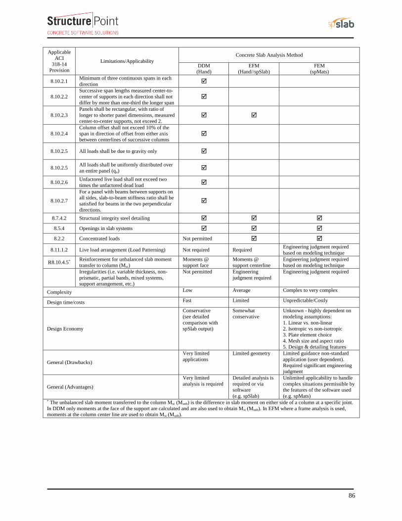
86
Applicable
ACI
318-14 Provision
Limitations/Applicability
Concrete Slab Analysis Method
DDM (Hand)
EFM (Hand//spSlab)
FEM (spMats)
8.10.2.1 Minimum of three continuous spans in each
direction
8.10.2.2 Successive span lengths measured center-to-center of supports in each direction shall not
differ by more than one-third the longer span
8.10.2.3
Panels shall be rectangular, with ratio of
longer to shorter panel dimensions, measured center-to-center supports, not exceed 2.
8.10.2.4
Column offset shall not exceed 10% of the
span in direction of offset from either axis between centerlines of successive columns
8.10.2.5 All loads shall be due to gravity only
8.10.2.5 All loads shall be uniformly distributed over
an entire panel (qu)
8.10.2.6 Unfactored live load shall not exceed two
times the unfactored dead load
8.10.2.7
For a panel with beams between supports on all sides, slab-to-beam stiffness ratio shall be
satisfied for beams in the two perpendicular
directions.
8.7.4.2 Structural integrity steel detailing
8.5.4 Openings in slab systems
8.2.2 Concentrated loads Not permitted
8.11.1.2 Live load arrangement (Load Patterning) Not required Required Engineering judgment required
based on modeling technique
R8.10.4.5* Reinforcement for unbalanced slab moment transfer to column (Msc)
Moments @ support face
Moments @ support centerline
Engineering judgment required based on modeling technique
Irregularities (i.e. variable thickness, non-
prismatic, partial bands, mixed systems,
support arrangement, etc.)
Not permitted Engineering
judgment required
Engineering judgment required
Complexity Low Average Complex to very complex
Design time/costs Fast Limited Unpredictable/Costly
Design Economy
Conservative
(see detailed
comparison with spSlab output)
Somewhat
conservative
Unknown - highly dependent on
modeling assumptions:
1. Linear vs. non-linear 2. Isotropic vs non-isotropic
3. Plate element choice
4. Mesh size and aspect ratio 5. Design & detailing features
General (Drawbacks)
Very limited
applications
Limited geometry Limited guidance non-standard
application (user dependent).
Required significant engineering judgment
General (Advantages)
Very limited
analysis is required
Detailed analysis is
required or via software
(e.g. spSlab)
Unlimited applicability to handle
complex situations permissible by the features of the software used
(e.g. spMats) * The unbalanced slab moment transferred to the column Msc (Munb) is the difference in slab moment on either side of a column at a specific joint.
In DDM only moments at the face of the support are calculated and are also used to obtain Msc (Munb). In EFM where a frame analysis is used, moments at the column center line are used to obtain Msc (Munb).


