Two-Dimensional CFD Simulation for Industrial Coal...
21
0 Two-Dimensional CFD Simulation for Industrial Coal-Water Slurry Entrained Flow Gasifier
Transcript of Two-Dimensional CFD Simulation for Industrial Coal...

0
Two-Dimensional CFD Simulation for Industrial Coal-Water Slurry Entrained Flow Gasifier

Two-Dimensional CFD Simulation for Industrial
Coal-Water Slurry Entrained Flow Gasifier
Speaker: Yu Zhang
Jun 8th, 2015
Huhhot, Inner Mongolia, China
Yu Zhang1, Andreas Richter2, Jian Xu1, Yong Yang1, Yongwang Li1
1Synfuels China Technology Co., Ltd., China,2IEC, TU Bergakademie Freiberg, Germany
email: [email protected]

Content Outline
Motivation and Purpose
Coal Water Slurry Gasifier Modeling
Simulation Results and Discussions
• Simulation Results
• Influence of Turbulence – Chemistry Interaction Model
• Non-reactive Cold and Reactive Flow Simulation Results
• Influence of Operation Condition
Conclusions
Outlook
2/19

Motivation
Coal is the major source of energy in China
Chemical products from coal: CTG, CTL, CTM (MTO,MTA)
Importance of gasification process
Process stability, overall efficiency, investment
Entrained flow gasification technology
Advantages: high carbon conversion ratio, wide adaption to different types of coal,
large production capacity
Challenges in developing entrained flow gasification
Fluctuate of coal qualities, scale up effect, harsh condition for experiment
Comprehensive model for entrained flow gasification
Optimization of gasifier design and operation condition
3/19

Purpose
Developing comprehensive coal water slurry (CWS) entrained flow
gasifier model
Evaporation, devolatilization, volatile decomposition, gas phase and char reactions
Comparing turbulence – chemistry interaction models
FR/ED model, EDC model
Analyzing simulated cold and reactive flow field
Sensitivity analysis of operation conditions
Pressure, coal water slurry concentration, droplet size distribution
4/19
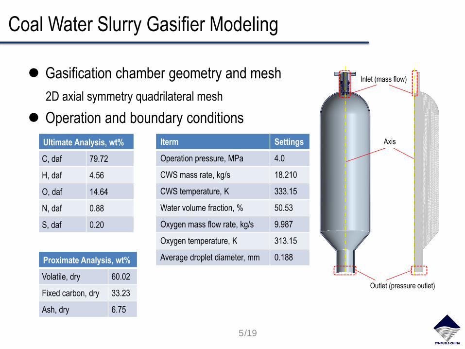
Coal Water Slurry Gasifier Modeling
Gasification chamber geometry and mesh
2D axial symmetry quadrilateral mesh
Operation and boundary conditions
Inlet (mass flow)
Outlet (pressure outlet)
AxisIterm Settings
Operation pressure, MPa 4.0
CWS mass rate, kg/s 18.210
CWS temperature, K 333.15
Water volume fraction, % 50.53
Oxygen mass flow rate, kg/s 9.987
Oxygen temperature, K 313.15
Average droplet diameter, mm 0.188
Ultimate Analysis, wt%
C, daf 79.72
H, daf 4.56
O, daf 14.64
N, daf 0.88
S, daf 0.20
Proximate Analysis, wt%
Volatile, dry 60.02
Fixed carbon, dry 33.23
Ash, dry 6.75
5/19

Sub-models
Evaporation Model
Diffusion controlled model
Pyrolysis Model
○ Devolatilization
single kinetic step rate
○ Volatile Decomposition
,
sat pp
p w i c i
p
p Tdm pA M k X
dt RT RT
1/2 1/3
,
2.0 0.6Rec p
AB d
i m
k dSh Sc
D
,0 ,0 ,01 1p
p v w p
dmk m f f m
dt
1 4 2 3 2 4 2 5 2 6 2 7 2Vol a CH a CO a CO a H a N a H S a H O
T, K P, MPa Mw a1 a2 a3 a4 a5 a6 a7
1000 4.0 18.468 0.425 0.124 0.113 0.194 0.016 0.003 0.124
75 7.4 10
3.82 10 expkRT
811 0.22.027 10
2.199 10 expVol VolR CRT
6/19

Reaction Mechanism
Homogeneous Reaction
Char Reaction
Turbulence – chemistry interaction model
Finite Rate/ Eddy Dissipation
Eddy Dissipation Concept
2 20.5CO O CO 2 2 20.5H O H O 4 2 20.5 2CH O CO H
2 2 2CO H O CO H 4 2 23CH H O CO H
20.5C O CO 2 2C CO CO 2 2C H O CO H
, , , , , ,
, , , ,
min ,PR P
i r i r w i R i r i r w i N
R r w R j r w jj
YYR v M A R v M AB
k v M k v M
1/4 1/2 2
2 2
2 31
3100 , * , *
4 3 * 1
D Di i i
D
C CR Y Y
C
7/19
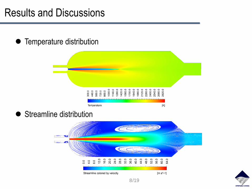
Results and Discussions
Temperature distribution
Streamline distribution
8/19
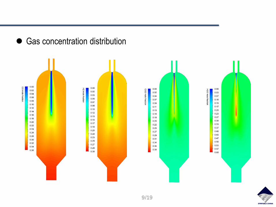
Gas concentration distribution
9/19
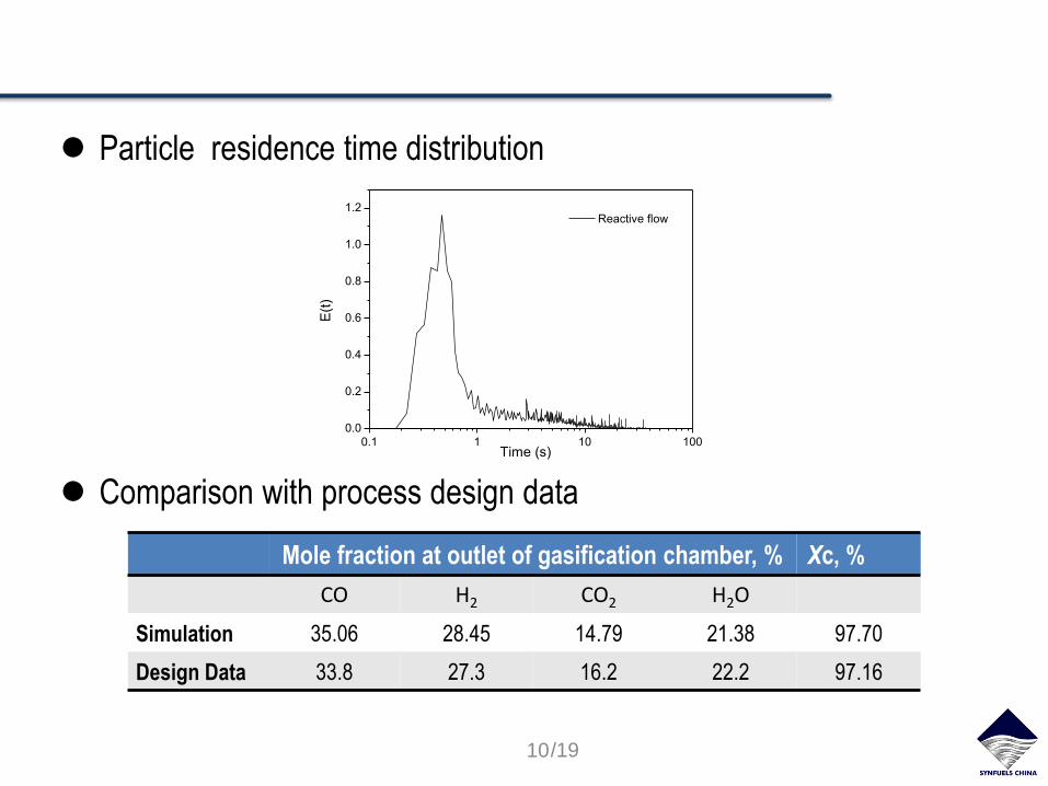
Particle residence time distribution
Comparison with process design data
Mole fraction at outlet of gasification chamber, % Xc, %
CO H2 CO2 H2O
Simulation 35.06 28.45 14.79 21.38 97.70
Design Data 33.8 27.3 16.2 22.2 97.16
10/19
0.1 1 10 100
0.0
0.2
0.4
0.6
0.8
1.0
1.2
Time (s)
E(t
)
Reactive flow

Influence of Turbulence – Chemistry Interaction
Turbulence – Chemistry interaction
Eddy Dissipation Model
Eddy Dissipation Concept Model
Comparison of ED and EDC models
, , , , , ,
, , , ,
min ,PR P
i r i r w i R i r i r w i N
R r w R j r w jj
YYR v M A R v M AB
k v M k v M
1/4 1/2 2
2 2
2 31
3100 , * , *
4 3 * 1
D Di i i
D
C CR Y Y
C
11/19

Mole fraction at outlet of gasification chamber, % Xc, %
CO H2 CO2 H2O
EDC Model 35.06 28.45 14.79 21.38 97.70
FR/ED Model 42.29 25.46 9.49 22.06 98.08
Design Data 33.8 27.3 16.2 22.2 97.16
12 /19

Non-reactive Cold and Reactive Flow Simulation Results
Comparison of streamline distribution
Particle residence time distribution
13/19
1 10 100
0.00
0.02
0.04
0.06
0.08
0.10
E(t
)
Time(s)
Cold flow
0.1 1 10 100
0.0
0.2
0.4
0.6
0.8
1.0
1.2
Time (s)
E(t
)
Reactive flow
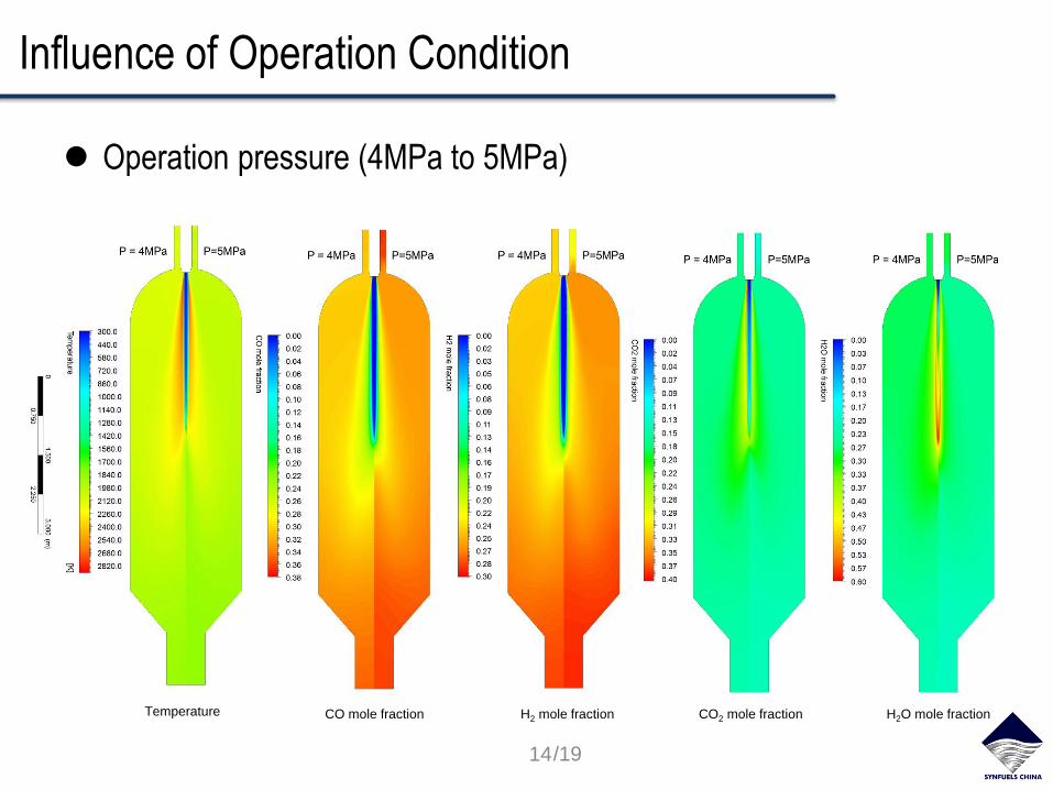
Influence of Operation Condition
Operation pressure (4MPa to 5MPa)
14/19
Temperature CO mole fraction H2 mole fraction CO2 mole fraction H2O mole fraction
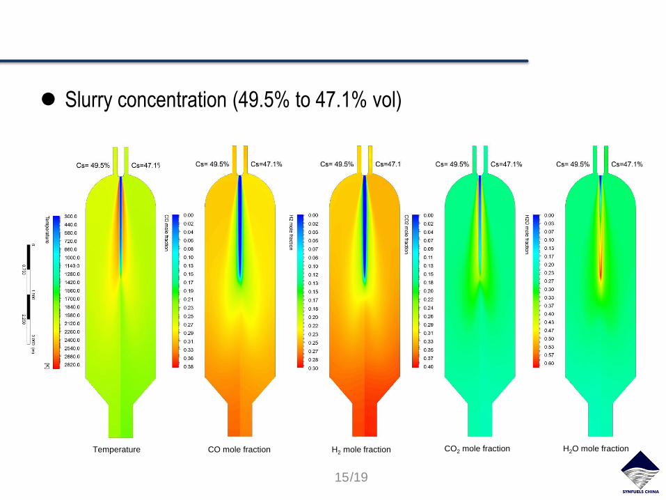
Slurry concentration (49.5% to 47.1% vol)
15/19
Temperature CO mole fraction H2 mole fraction CO2 mole fraction H2O mole fraction

Mean droplet diameter (188μm to 376μm)
16/19
Temperature CO mole fraction H2 mole fraction CO2 mole fraction H2O mole fraction
Conclusions
The comprehensive 2-D CFD model for industrial CWS gasifier is
approved by process design data.
Comparison of CFD results obtained by FR/ED and EDC are
presented. The simulation results show that EDC model is more
suitable for gasification simulation.
Significant differences of streamline distribution and particle
residence time distribution for cold and reactive flow simulation are
observed. The jet-core region is elongated since gas releasing in
reactive flow.
Ascending operation pressure increases syngas yield, and low slurry
concentration leads to less CO concentration and higher H2/CO ratio.
The coarse particle results in lower syngas concentration and carbon
conversion ratio.
17/19

Outlook
Specifying volatile decomposition and char reaction kinetic
parameters based on experiment data.
Implementing sensitivity analysis of sub-models including turbulence,
evaporation, devolatilization and volatile decomposition models, and
mesh independent check.
Comparison of 2D and 3D CFD models of gasification chamber.
18/19
Acknowledgements
Supported by Synfuels China Co., Ltd. and collaborated
with TU Bergakademie Freiberg IEC
CollaboratorsDipl. –Ing. Fengbo An, Dipl. –Ing. Thomas Fö rster, Dr. –Ing. Dmitry Safronov,
M. Sc. Yury Voloshchuk
19/19

Our Expertise Energy In Future
Thank you for your attention