TV ANTENNA FOR 600 MC. - World Radio History
46
TV ANTENNA FOR 600 MC.
Transcript of TV ANTENNA FOR 600 MC. - World Radio History

TV ANTENNA FOR 600 MC.
LOW DISTORTION SIGNAL SOURCE FOR BROADCAST ,_SUREMENTS
-hp- 201B AUDIO O
[PCP RAMIE
MO, *. I,[1YCTT PA.I.0 PALO ALTO OALICORYIA ,P ,. G
pp__ 1, L, / ` ,
'S,
ú" b PFlROOC A1I[MW1WN
SPECIFICATIONS Frequency Range: 20 cps to 20 kc, in 3 bands
X 1-20 to 200 cps
X10-200 to 2,000 cps
X 100- 2,000 to 20,000 cps.
Frequency Calibration: Direct in cos for Ir -
est band. Effective scale length tor 3 b... is 47 inches.
Stability: Better than ±2 %, including warm - up drift.
Output: 3 watts or 42.5 volts into 600 ohm load. Frequency Response: Within ±1 db over
entire frequency range. Distortion: Less than 1% at 3 watts output.
Less than 0.5% at 1 watt output, at fre- quencies above 50 cps.
Hum Level: Less than 0.03% of maximum am- plifier output voltage.
Dota subject to change without notice.
FREE HOW- TO -DO -IT MANUAL FOR F. C. C. MEASUREMENTS
Broadcast Engineers: Write for new, 37- page manual. De- tailed instructions for making F. C. C. sta- tion performance measurements. Rec-
ommended circuits, step -by -step pro- cedures, charts for calculating data, recommended forms for characteristic curves. Limited quantity. Write on station letterhead- today!
OR
EASY TO USE
INEXPENSIVE
HIGH OUTPUT
LOW DISTORTION
Broadcast stations across the country find this high -fidelity -hp- 201 B Audio Oscillator an ideal signal source for broadcast measurements, including new station performance data now required by the F. C. C. It meets every FM or AM requirement for speed, ease of operation, accuracy and purity of wave form. It enables you to quickly, easily and accurately make such meas- urements as high fidelity amplifier tests, overall station frequency response, overall station distortion, studio- transmitter line characteristics, etc.
3 WATTS OUTPUT The -hp- 201B provides 3 watts of output power into a 600 ohm resis- tive lead, sufficient to drive almost any kind of broadcast, laboratory or production equipment. Distortion may be limited to less than 0.5% at power of 1 watt or less. Hum level and output level can be attenuated together, and hum level is held 70 db under signal level for accuracy in working with small test signals.
20 TO 20,000 CPS
The instrument has a frequency range of 20 to 20,000 cps, covered in 3
bands. Frequencies can be tuned di-
rectly or by a 6:1 vernier control.
Effective scale length is about 47" and the no- parallax tuning dial has 95 calibration points occupying 300 de- grees of the scale. The entire instru- ment is rigidly constructed for long service; sturdy, light weight and easy to handle. It is completely powered from any 115 volt ac power source.
Get complete details. See your nearest -hp- representative or write direct.
HEWLETT -PACKARD CO. 1878 -F Page Mill Road, Palo Alto, California
Export: FRAZAR & HANSEN, LTD. 301 Clay Street, San Francisco, California, U.S. A. Offices: New York, N. Y.; Los Angeles, Calif.
laboratori,' instruments

fM`Í' FEED LINE
+*-90° ELBOW MI-19112-2
Close -up view of the BAF -14A with the shield removed.
Type BAF -14A, installed
...isolates the feed from your AM tower New design -New low price*
The new RCA Type BAF -14A Isolation Unit enables you to transfer FM power effec- tively across the insulating zone of your AM tower ... and makes it possible to completely isolate the FM and AM signals from each other. The unit maintains a low standing wave ratio on any FM channel and has minimum effect on AM tower impedance. Type BAF -14A will handle up to 10 kilowatts of FM power -with AM base insulator voltages up to 14 kv, peak!
In this Isolation Unit, two series -resonant circuit loops are coupled to each other in such a way as to provide excellent band -pass char- acteristics over the range of 88 to 108 Mc. Each circuit connects directly to its respective input or output transmission line- terminating
in an end -seal. Provision is made to carry the gas pressure line across the unit.
It's a simple matter to connect up the BAF -14A ... because the input and output ter- minals are both equipped with special swivel flanges that eliminate expensive special coaxial fittings.
Built in a weatherproof metal box, only 12" x 12 ", the BAF -14A Isolation Unit is delivered ready to go. No tuning or adjust- ments to go through after installation.
Ask your RCA Broadcast Sales Engineer how the BAF -14A can solve your tower cou- pling problem. Or write Dept. 38F, RCA Engineering Products, Camden, N. J. *Ask your Broadcast Sales Engineer
BROADCAST EQUIPMENT RADIO CORPORATION of AMERICA ENGINEERING PRODUCTS DEPARTMENT, CAMDEN, /V.J.
In Canada: RCA VICTOR Company Limited, Montreal
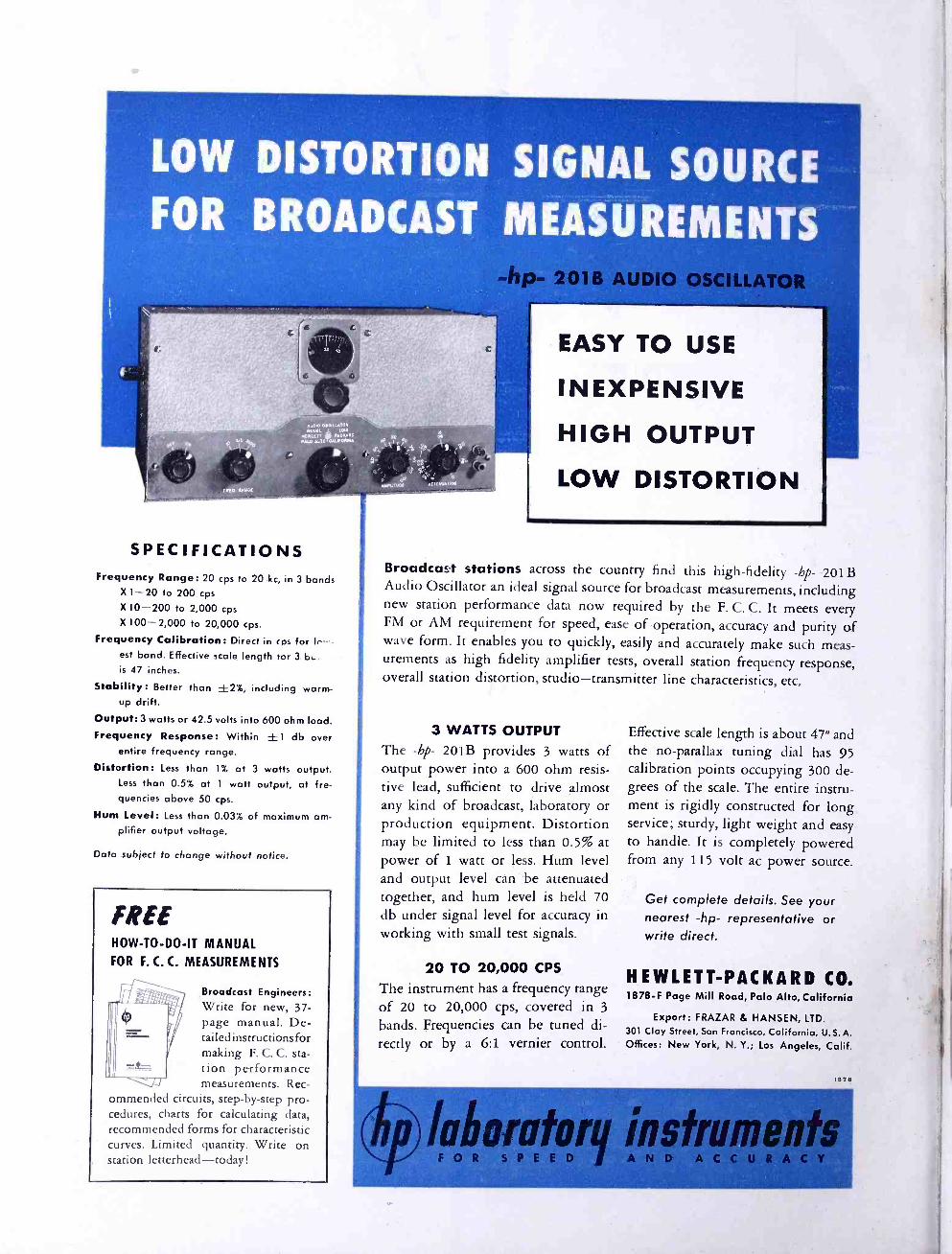
NOV--A COMPLETE LINE!
ZENITH TELEVISION WITH
GIANT CIRCLE SCREEN and BULLS EYE AUTOMATIC TUNING
From the ultra- magnificent combinations to the beautifully streamlined table models, every Zenitht Television set hits the "bulls eye" for sales appeal. Every one has the sensational Zenith ad- vancements found in no other television set ... the Giant Circle Screen for a bigger, brighter, clearer picture ... and Bulls Eye Automatic Tun- ing -one knob, one twist, there's your station, your giant picture, your sound ... automatically pre -tuned to perfection!
Yes, Zenith has what it takes to assure the ulti- mate in customer satisfaction and bring you the most beautiful profit picture in television.
SEE YOUR ZENITH DISTRIBUTOR
ZENITH RADIO CORPORATION 6001 Dickens Ave., Chicago 39, III.
THE ZENITH GOTHAM. Zenith Television with "Big B" Giant Circle Screen; "Twin Cobra "t Tone Arms; Genuine Zenith -Armstrong FM and Zenith long distance AM radio; all superbly combined in a console of breath- taking beauty in imported mahogany veneers. 195
(plus Federal excise tax.)
THE ZENITH MARLBOROUGH. Super deluxe! Zenith Television with "Giant C" Giant Circle Screen. Plus "Twin Cobra" Record Player; FM -AM and Short Wave Radio. In an authentic Regency console of hand glazed Honduras mahogany veneers, a masterpiece of the furni- ture craftsman's att. . . (plus Federal excise tax. ) $11 5Q`
THE ZENITH WALDORF. Modern television console of imported Afara veneers in blonde finish. With "Big B" screen.
$48995 WILSHIRE model with "Super A" screen, $449.95. Both models also available in mahogany finish.
THE ZENITH MAYFLOWER. Period table set in mahog- any- finished veneers of im- ported Afara. Has " Super A" television screen. $38995* Matching table, 26 inches high, available at $29.95.* Receiver and table also in blonde finish.
1TH HAS THE GREAT VALUES
TELEVISION and long distance RADIO
*Suggested retail price. West Coast prices slightly higher. Prices subject to change without notice.
2 FM ANI) TELEVISION

I
Formerly, Fil MAGAZINE and FT/ RADIO -ELECTRONICS
VOL. 9 June, 1949 NO. 6
COPYRIGHT 1949, by Milton B. Sleeper
CONTENTS
INDUSTRY NEWS
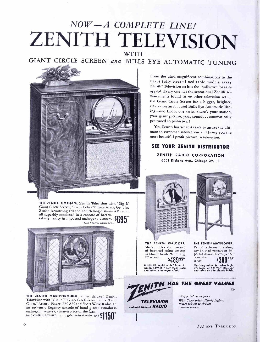
TV -FM -AM Set Production Compiled from figures released by the RMA 4
What's New This Month 1. FCC's new TV plans 2. Jeremiah Courtney's Page
3. Optical Service for TV 4. Motorcycle Radio Equipment 8
FREQUENCY MODULATION
Equipment for Remote Pickups Frederick T. Budelman 13
Radio Communications Services, Part 1
New FCC rules and allocations 17
TELEVISION
TV Operation in Small Cities E. J. Meehan 24
Choosing the Right Antenna Notes on improved designs 27
APPARATUS DESIGN
Carbonyl Iron Powders George O. Altmann 29
AUDIO DEVELOPMENTS
Generator for AF Measurements W. Noel Eldred 31
SPECIAL DEPARTMENTS
Television News 6 Special Services Directory 9 Professional Directory 10 Spot News Notes 22 News Picture 23
THE COVER DESIGN AND CONTENTS OF FM AND TELEVISION MAGAZINE ARE
FULLY PROTECTED BY U. S. COPYRIGHTS, AND MUST NOT BE REPRODUCED IN ANY MANNER OR IN ANY FORM WITHOUT WRITTEN PERMISSION
MILTON 13. SLEEPER, Editor and Publisher CHARLES FOWLER, Business Manager
LILLIAN BENDROSS, Circulation Manager Published by: FM COMPANY
Publication Office: 264 Main St., Gt. Barrington, Mass. Tel. Gt. Barrington 500
FM -TV Magazine is issued on the 20th of each month. Single copies 25c - Yearly subscription in the U. S. A. $3.00; foreign $4.00. Contributions will be neither acknowledged nor returned unless accompanied by adequate postage, packing, and directions, nor will FM -TV Magazine be responsible for their safe handling in its office or in transit.
Entered as second -class matter August 22, 1945, at the Post Office, Great Barrington, Mass., under the Act of March 3, 1879. Additional entry at the Post Office, Boston, Mass. Printed in the U. S. A.
*PoucsALaRM o
POLICE CALLS TAXI CABS
AND OTHERS
Radio Receiver Tunes
Emergency Communications
Band ... 152-162 Megacycles
NEW IMPROVED MODEL PR -7
True F.M. superhetrodyne, 6 miniature tubes, in-
cluding rectifier. 110 volts, AC -DC, 5 -inch speaker, highest quality components.
Attached Antenna .; Clear Vision dial Siie 101/4" x 6 %" x sii Discriminator detector
$3995 Deluxe CA -2 reception, list
outside price onl
LIST PRICE includes excise tax, F.O.B. Indianapolis. $10. cash with order, balance C.O.D.
coaxial antenna for best $5 y °
See your DEALER first, or write Dept. FBI -1.
RADIO APPARATUS CORP. 303 FOUNTAIN SQUARE THEATER BLDG
INDIANAPOLIS 3, INDIANA
Rugged, accurate
RESISTANCE BOXES
for use in testing laboratory work, and
as components in
bridge work?
If you do, write DEPT. FM -10 for further information.
THE DAVEN co., 1 9 1 C E N T R A L A V E N U E
N E W A R K 4 , N E W J E R S E Y
MEMBER, AUDIT BUREAU OF CIRCULATIONS
3
THE NEW
NATIONAL HFS $142
(power supply extra)
Complete Coverage 27 mcs -250 mcs!
Covers all mobile com- munication services, as well as fixed services. Re- ceives CW, AM OR FM! Superheterodyne with superregenerative 2nd detector.
Mobile, Portable or Fixed!
Operates from standard 110 volt, 60 cycle Na- tional 5886 power sup- ply, National 686S 6- volt vibrator -type power supply or batteries! Built - in speaker. Light.
See your nearest National dealer listed in the classified section of your 'phone book.
NATIONAL COMPANY, Inc. M A L D E N , M A S S A C H U S E I T S
4
RMA set production figures for April were not available up to June 1st due, we were told, to delay by one of the larger manufacturers in making his report.
April marked the beginning of price re- ductions on receivers, and the end of a period when RCA was the principal source for components. It will be re- membered that RCA not only made the design of its first TV production model available to licensees, but also the indi- vidual parts. Thus manufacturers could start their own set production quickly. No doubt, RCA priced their components at a level which returned some of their heavy investment in engineering and tools. In the light of costs developed since the licensees got going on their own, RCA prices proved high, but initial assistance served its purpose.
Only disturbing, cloud on the horizon is the UHF question. Probably the large producers will be able to add UHF tuning and keep the cost down at the level already established for VHF sets.
N
om- o á
-
N -
-
N -
f
4a
-AM
-FM - TV
d
Others won't be able to absorb the ex- pense and troubles involved.
Last January, we said: "FM is going to b'e the safest bet profit -wise for conserva- tive- minded manufacturers and re- tailers." With AM sagging at the knees, and TV faced with allocations problems, FM has the advantage of a stable base. It's the only prop for audio broadcasters who have just discovered that the high - power promotion employed by TV opera- tors is selling the foundations from under their towers.
Commander McDonald seems, at this moment, to be the only major producer to play both FM and TV to the middle. Thus, while Zenith is going along with the television parade, it is carrying an FM egg- basket on the other arm, there- by winning the active support of the audio broadcasters. Also Zenith dealers in rural areas have something superior to sell where there is no television, and those in the cities have something to offer people who don't buy TV sets.
4- MONTHLY -H A vERAGE
1947
o o
4
N- MONTHLY --H AVERAGE
1948
la- MONTHLY -.+ AVERAGE
JAN.- MAR. 49
o
JFMAMJJASONDJFMAMJJASOND 4- 947 .a 1948--- JFMAMJJASOND
-TV 8 FM-TV 1949--- JFMAMJJASOND
FM-AM 1949 ><
- O.
-0
JFMAMJJASOND
-.p
-J1
o
-4
N
Oi o a o _ N
O
AM 1949
TV, FM, and AM Set Production Barometer, prepared from RMA figures
FM AND TELEVISION

The farmer in the field and his wife at home will be able to converse with ease by using these new, lightweight trans - ceivers equipped with Sylvania sub -miniature tubes!
Tiny Sylvania sub -miniature radio tubes, smaller than a lady's little finger, are big reasons why the Citizens Radio Transceiver meas- ures only 6" long, not quite 3" wide, 11/4" deep, and weighs only eleven ounces!
Sold in sets of two, these tiny two-way transceivers with a range of several miles are tuned to 465 mc. Among the many who want these handy units are police and fire departments, surveyors, farm-
SYLI' ELEC
ers, hunters, industrial users, rangers and those who wish boat - to -home and auto -to -home com- munications.
Sylvania's extensive radio tube research and manufacturing skill have made Sylvania sub -miniature tubes the choice of Citizens Radio Corporation, Cleveland, for this revolutionary, civilian transceiver. Sylvania Electric Products Inc., Radio Tube Division, Emporium, Pennsylvania.
NIA RIC
RADIO TUBES; CATHODE RAY TUBES; ELECTRONIC DEVICES; FLUORESCENT
LAMPS, FIXTURES, WIRING DEVICES; LIGHT BULBS; PHOTOLAMPS
June 1949 -formerly FM, and FM RADIO- ELECTRONICS 5

A Message to Operators of
MOBILI: RADIO SYSTEMS COINCIDENT with the release of new FCC rules and allocations for mobile radio, FM -TV Magazine is expanding its editorial serv- ice to communications supervisors and engineers, and to owners of mobile radio systems.... For the past nine years, FM-TV has been the leading publication in this field. In fact, it has consist- ently devoted more space to mobile radio equipment and systems than all other magazines combined. . . . It is natural that this should be so, not only because the real expansion of mobile communications began with the development of 2 -way FM equip- ment, but because the Editor of FM -TV was one of the pioneer engineers in the communications field, and has had an active part in the development of mobile radio since 1934... . Since that time, the narrow low -frequency hand originally used only for police radio has grown to a total of 616 channels between 25 and 470 nie., used by many services. The total bandwidth is
32 mc., 36 times the bandwidth occupied by AM broadcast stations! . . . New allocations and rules mean new FCC actions affecting present and future operations. These will be discussed each month by Jeremiah Courtney, former FCC Assistant General Counsel... . Problems of adjacent -channel assignments, reduc- tion of interference, combined operations, limitations on frequency stability and modulation, planning new systems in
accordance with FCC rules, and the use of operational fixed stations will all be covered in detail by men who are specialists in these subjects. . . . And, of course, semi -annual Directory of Mobile Radio
FM -TV feature, available from no other
we shall continue the Systems, an exclusive
source. July presents the newly- revised list of all systems operated by police, fire, forestry, railroads, and petroleum companies. All other systems, including taxis, public utilities, trucks and buses, are listed, with up -to -date revisions, in January.... Li short, FM -TV pro- vides, in one magazine, complete operational and technical information on present and future applications of mobile radio for all services. The cost is $6 for three years, or $3 for one year. If you are not already a subscriber, use the order blank attached.
FM -TV MAGAZINE GREAT BARRINGTON, MASS.
vIsIO\T `1. J = `EWS
Paid TBA President: May be FCC Chairman Coy, if he will accept the post. Proposal was sub- mitted by commilttee comprising Jack Poppele, Dr. Du Mont, Lawrence Low -
'man, and G. Emerson Markham. Salary would be $25,000 to $35,000. Purpose would be to develop public relations and represent TBA in technical, regulations, and legislative matters.
Pressure on TV Permittees: FCC has refused additional construction time to WJAX -TV and . WPDQ -TV, Jacksonville, and WEEK -TV, Peoria. Also, WMBR -TV, Jacksonville, and WAFM -TV, Birmingham, were turned down on requests for permission to oper- ate on interim power of 500 watts.
First TV Anniversary in Boston: WBZ -TV, Boston's first station, started transmission on May 29, 1948. Since that time, 81,390 receivers have been in- stalled in the Boston service area.
Add These TV Stations: Since the list of TV stations on the air was published last month, KFMB -TV, San Diego, has started regular programs, using channel 8, and KGO -TV, San Francisco, is now operating on channel 7. These bring the total to 63 stations.
West Coast Rebroadcast: When KFMB -TV, San Diego, went on the air May 16, the Hoffman Hayride program was rebroadcast by direct pick- up from KTLA, Los Angeles, and Klaus Landsberg, general manager of KTLA, sent his greetings to the San Diego audi- ence. The distance between KTLA's transmitter on Mt. Wilson and KFMB- 'l'V's pickup receiver on Mt. Soledad is 1 25 miles.
ATS Officers Elected: David Hale Halpern, vice . president of Owen and Chappel, Inc., has been elected president of the American Television Society, succeeding Charles J. Durban of U. S. Rubber. New vice president is Donald E. Hyndman, Eastman Kodak; secretary, Reynold R. Kraft, N. B. C.; treasurer, Archibald V. Braunfeld. Di- rectors are Charles J. Durban; Georoge Shupert, Paramount; Ralph Austrian, Ralph Austrian, Inc.; Maurice Strieby, A. T. & T.; Edgar P. James, MBS; Hal- sey V. Barrett, Du Mont; and Jerry A. Danzig, CBS. Headquarters of . ATS are at 11 E. 45th Street, New York 17.
FM AND TELEVISION

THE products listed here are described in new catalogs and bulletins now avail-
able. Unless otherwise noted, they will be sent on request, without charge.
Transmitting Tubes: Quick reference data on 9 types of tetrodes, 25 triodes, 8 rectifiers, and associated com- ponents. Included are multiple triode assem- blies for high power at VHF. Eitel- McCul- lough, Inc., San Bruno, Calif.
Broadcast Equipment: Four separate brochures describe: an FM broadcast transmitter of 1 to 5 kw. output for stations authorized to use up to 60 kw. effective radiation a super -power FM trans- mitter of 10 to 50 kw. output; a universal control console of flexible design which can be used at FM, AM, and TV stations and an isolation unit to transfer FM power across the insulating zone of an AM tower. Complete technical data is given on this equipment. RCA Victor Division, Engineering Products Department, Camden, N. J.
Service Signal Generator: Covers all frequencies used for mobile com- munications, as well as the upper TV chan- nels, with over 100 ins. of calibrated scales, accurate to .05 %. Modulated and unmodu- lated output from 1 to 100,000 microvolts. Self- contained crystal oscillator. Model 292X. Hickok Elect. Inst. Co., 10530 Dupont Ave., Cleveland 8, Ohio.
JAN -Type Capacitors: Complete specifications and dimension draw- ings are presented in quick- reference form in a 32 -page catalog. Cornell -Dubilier Electric Corp., South Plainfield, N. J.
6AB4 Miniature Triode: For use as a grounded -grid RF amplifier and local oscillator for TV sets. Heater is de- signed to reduce microphonics and hum level. General Electric Co., Tube Division, Schnec- tady, N. Y.
Data on Lucite: Entitled "DuPont Lucite Acrylic Resin," a new 32 -page book presents application data and information on handling and fabricating this versatile material in cast sheet form. E. I. DuPont De \'emours & Co., Wilming- ton 98, Del.
Filament Transformers: Type 203T1 is designed for the 5771, and type 2O3T2 for the 5786 power tubes. No auxiliary current -limiting reactor is required. The former, limiting the filament starting current to 800 amperes, has 6 taps for line voltages of 195 to 250 volts. The latter limits the starting current to 50 amperes, and is tapped for 105, 115, and 125 volts. RCA Tube Department, Iarrison, N. J.
Subminiature Tubes for Portables: Four new types have 8 -pin leads for sockets or printed- circuit connections. Seated height is 11/2 ins., diameter .4 in. The series com- prises: lADS sharp -cutoff RF pentode; 1E8 pentagrid converter; 1T6 diode- pentode; and lACS output pentode. Plate potentials range from 30 to 67.5 volts, plate current .3 to 2 milliamperes. Sylvania Electric Products, Inc,. 600 Fifth Ave., New York 17.
7/oaf/n for all Action! . T V Cameras
"BALANCED" TV TRIPOD
Pat. Pending
This tripod was engi- neered and designed ex- pressly to meet all video camera requirements. Previous c o n c e p t s of gyro and friction type de- sign have been discarded to achieve absolute bal- once, effortless operation, super - smooth ti I t and pan action, dependability, ruggedness & efficiency.
Below: 3 -wheel portable dolly with balanced TV Tripod mounted.
Complete 360° pan without ragged or jerky movement is accomplished with effortless control. It is impossible to get anything but perfectly smooth pan and tilt action with the "BALANCED" TV Tripod.
Quick -release pan handle ad- justment locks into position desired by operator with no "play" between pan handle and tripod head. Tripod head mechanism is rustproof, corn - pletely enclosed, never re- quires adjustments, cleaning or lubrication. Built -in spirit level. Telescoping extension pan handle.
Write for further particulars
FRANK C. ZUCKER
CAMERA EQUIP111EITC.
1600 BROADWAY OEW WORK CITY
811 -A Power Triode: Improved version of the 811 features a zirconium -coated plate with radial fins for greater dissipation, reduced RF loss from grid and plate leads, and strengthened top - cap assembly with ceramic collar. RCA Tube Department, Harrison, N. J.
Circuit Markers: Self- adhesive tabs, % in. square, for identify- ing terminals, harnesses, and switches. Fur- nished 40 to the card, they are numbered 1
to 10, 1 to 20, or 1 to 40, and in letter series A to Z. Western Lithograph Co., 220 Rose St., Los Angeles 54.
Deflection Amplifier Tubes: Moderately -priced types 6BQ6GT and 25BQ6GT are intended to reduce the cost of deflection circuits. Hytron Radio & Elec- tronics Corp., Salem, Mass.
June 1949 -formerly FM, and FM RADIO -ELECTRONICS
NAB Equalizer: Modifies the frequency characteristics of a recording system to conform with NAB rec- ommendations for lateral transcriptions. Mounted on a 19 -in. rack panel 13/4 ins. high. If 22 -db insertion loss is too high, equalizer is supplied with a preamplifier booster, mak- ing panel 31/2 ins. high. Fairchild Recording Equipment Corp., Whitestone, N. Y.
Remote TV Control: Control with 50 -ft cable turns set on or off, tunes stations, and controls contrast and brightness. Operates with any type of TV set. Transvision, Inc., New Rochelle, N. Y.
Stylus Force Gauge: Gauge calibrated 0 to 40 grams shows stylus force when needle is set in an indentation on test arm. Gray Research & Development Co., 16 Arbor St., Hartford, Conn.
7

Recettio for
Buses, Streetcars Supermarkets Stores, Hotels Restaurants
and
Public Buildings FIXED FREQUENCY Crystal Controlled EXTREME SENSITIVITY Better Than 1 Microvolt HIGH AUDIO OUTPUT Full 8 Watts NEGLIGIBLE DISTORTION Less Than 5 Percent HIGH FIDELITY Essentially flat 50- 15,000 cycles TONE CONTROL Bass and Treble Control VOICE ACCENTUATION 10 db Rise for Commercial Announcements REMOTE CONTROL Audio Silencing under Control of Broadcasting Station TAMPER -PROOF ASSEMBLY Equipment Sealed in Locked Cabinet
ESE AND MANY OTHER FEATURES ASSURE TSTANDING PERFORMANCE WITH A MINIMUM MAINTENANCE AND A MAXIMUM OF SERVICE.
RE IS A REALLY GREAT RECEIVER IN THE TRUE NK TRADITION OF QUALITY THAT HAS MADE NK COMMUNICATIONS EQUIPMENT "PREFERRED
E WORLD OVER."
Link Radio Corporation 125 W. 17t4 St., Now York 11, N. Y.
THIS MONTH'S COVER This month's cover, is not a pic-
ture of something to strain min- nows from the ether waves. Rather, it shows what is coming by way of housetop antennas for UHF televi- sion. Dr. Goldsmith, of DuMont Laboratories, has been using this antenna to pick up images from sta- tion VVIOXKT,located at the site of WARD. Details of Dumont trans- mission on 600 mc. were presented in FM -TV last month.
Now that the FCC has announced definite plans to make commercial TV assignments in the UHF band when the present freeeze ends, we can expect to see a new crop of an- tenna designs.
WH T'S NEW THIS MONTH NEW TV PLAN,
2. JEREMIAH COURTNEY'S PAGE
3. OPTICAL SERVICE FOR TV
4. MOTORCYCLE RADIO EQUIPUI \ I
1 As we had anticipated, research dur-
. ing the period of the television freeze brought to light the fact that the 12 VHF channels will not accommodate the 459 TV stations originally planned by the FCC.
The first official word from the Com- mission was released on May 26, in an announcement which puts the industry on notice that it must prepare for the 6 -mc. transmission and reception on UHF. The further implication is that some present VHF applicants are going to get UHF assignments, and that, if there are going to be VHF channels still open anywhere, they'd better be gobbled up quickly.
Here is the exact and complete text of the Commission's announcement re- leased on May 26:
The Federal Communications Commis- sion announced today that, in accord- ance with plans adopted Friday, May 20, 1949, it will institute further proceedings looking toward, 1) lifting the freeze on the present VHF television band, 2) providing a substantial number of UHF channels for commercial television broad- cast service, 3) affording an opportunity for the submission of proposals looking toward the optional use of 6 -mc. color in all channels in such a way as to permit reception on an ordinary television re- ceiver with relatively minor modifica- tions, and 4) adopting a nation -wide as- signment plan covering commercial op- eration in both bands.
The Commission finds that these prob- lems are so closely related that it is not feasible to lift the present TV freeze without first having more channels available and an overall allocation plan. Accordingly, it proposes to utilize ap-
proximately one -half of the lower portion of the UHF band for regular television operation on 6 -mc. channels. This band has been available for operation on an experimental basis. The upper portion of the band will be kept open for tele- vision research such as stratovision, poly - casting, and high- definition monochrome and color.
The Commission also proposes to af- ford an opportunity for the submission of proposals looking toward utilization of all television channels for 6 -me. mono- chrome or color on an optional basis in such a way as to permit reception on the ordinary television receiver with rel- atively minor modifications.
The Commission desires to emphasize that if, as a result of these proceedings, it is shown that color television can be operated satisfactorily within a 6 -mc. channel in such a way as to permit re- ception on the ordinary television re- ceiver with relatively minor modifica- tions, the commission will make provision for licensing stations both in the VHF and UHF bands when it is shown that sufficient receivers and parts are avail- able to permit adapting monochrome receivers for color reception.
The combined schedule calls for pro- posed rule making proceedings as re- quired by the Administrative Procedure Act. A Notice of Proposed Rule Making will be issued within approximately six weeks from this date. The proposed rules will not only cover the contem- plated use of channels in the UHF band but will also contain a revised allocation table for the present VHF band, taking into consideration the propagation studies of the ad hoc committee.
(Continued on page 9)
FM AND TELEVISION
Special Services Directory
METHODS ENGINEERS Materials & Methods engineers in America's leading manufacturing plants use Topflight's Printed Cellophane, Self - Adhesive Tape to meet A -N specs. - assembly line - follow through - instruction labels. Easy to Apply.
TOPFLIGHT TAPE CO. YORK PA.
P" 300 MM. Code Beacons
Obstruction Lights Code Flashers
Packaged Lighting Kits Send for Catalogue
HUGHEY & PHILLIPS 326 North La Cienega Blvd.
los Angeles 36, Calif.
THE WORKSHOP ASSOCIATES
INCORPORATED
Specialists in High- Frequency Antennas
66 Needham St., Newton Highlands, Mass. Bigelow 3330
RATES FOR
SPECIAL SERVICE CARDS
IN THIS DIRECTORY
$12 Per Month for This Standard Space. Orders Are Accepted
for 12 Insertions Only
RADIO -MUSIC CORP. REPRODUCERS TURNTABLES
AMPLIFIERS 1 SPEAKERS
F. M. broadcast quality for custom sound installations for the studio and the home.
PORT CHESTER, NEW YORK
June 1949 formerly FM, and
WHAT'S NEW THIS MONTH (Continued from page 8)
Upon issuance of the proposed regu- lations, approximately thirty days will be allowed for submission of comment or alternative proposals by those interested. A hearing will follow within ten days or two weeks. Within two weeks after the hearing, the Commission will hold oral argument preparatory to a final deci- sion which will be given priority consid- eration.
The Commission will attempt to con- clude the proceedings as soon as prac- ticable after a fair opportunity is given for hearing all interested persons and allowing for due consideration of the matters presented. In view of the above required procedure, it does not appear that a final decision can be made before late fall. However, the ultimate decision will not only involve lifting the freeze but, at the same time, resolve other closely related problems.
It should be noted that Commissioner Freida B. Hennock, did not approve of releasing the foregoing announcement at this time. Her dissenting opinion was expressed by a separate statement, in accordance with FCC practice. The com- plete text follows:
I am keenly aware of the intense in- terest in the progress of television shared by members of the public generally, and especially the families contemplating purchase of television sets, by manufac- turers, and by station licensees. But I am aware also of the many problems that exist as to the future status of black - and -white television, color television, both in the present VHF bands and the proposed UHF bands, and the multitude of other questions which must be solved to insure the finest development of this great new art for as many people as pos- sible. I feel strongly that these ques- tions must be carefully deliberated and thoughtfully answered in the manner which Congress has prescribed, by the orderly conduct of rule- making proceed- ings in accordance with the Administra- tive Procedure Act, 5 U. S. C. Sec. 1003. We are now in the midst of such proceed- ings, in which all interested persons are being afforded a full opportunity to par- ticipate, present their views, and offer technical information, and are in a posi- tion to issue a further notice of proposed rule making, looking toward an early solution of these difficult problems which confront us. And I feel that we must patiently continue to move forward in this orderly manner with confidence that we are performing our duty conscien- tiously and in a way which will, in the end, supply the fullest answers with the most adequate protection for the inter -
(Continued on page 10)
FM RADIO- ELECTRONICS
Professional Directory
AMY, ACEVES & KING, INC. Specialists in the
Design and Installation of
HIGH -GAIN AM, FM, and TELEVISION
ANTENNA SYSTEMS LOngacre 5 -6622
11 West 42nd St., New York 18, N. Y.
RANGERTONE TAPE RECORDERS
HIGH -FIDELITY EQUIPMENT FOR BROADCAST& RECORDING STUDIOS
RANGERTONE, INC. 73 Winthrop St. Newark 4, N. J.
Tel. Humbolt 5 -2550
Collins //
Custom Components
_Jhe llerfy 7ineií FM TUNERS FM /AM TUNERS
FM RECEIVERS Custom Matched Components
CoffinJ Audio Products Co., Inc.
P. 0. Box 368 . Westfield, N.J.
It's Alden for .. .
facsimile dispatching equipment
designed for your specific purposes. It may be for wire or for radio circuit. A pilot operation - or in quantity
production Our engineering provides for messages to be
automatically picked up at scanner with record- er starting, stopping, and framing automatically, controlled by transmitter.
Alden Engineering experience covers the range of operations from low speed for narrow band- width wire lines to high speed large area equip- ment.
So whether you are dispatching a memo from office to office - or a full sire weather map across the country -Alden has the system and will make to special order equipment that fits your needs. For instance - 200 cycle bandwidth 15KC bandwidth
Memo Newspaper Map with 4" width -50 LPI with 18" width -100 LPI
2 in /min. 9 in /min.
OR
Alden engineering opens new fields in impulse recording
Filling the gap between indicating instruments and the Cathode Ray Oscilloscope.
Giving a permanent record directly without photographic processes.
Alden Recording Equipment operates with Al- fax Electrosensitive Recording Paper producing permanent recordings. Alfax is a sensitive high 'Speed paper that does not require special packag- ing. It is stable in storage, and is permanent in its recording.
To solve that facsimile or impulse recording problem. - write now to
ALDEN PRODUCTS CO. Brockton 64FD, Massachusetts
9

Professional Directory
flan4 RaiCey AN ORGANIZATION OF
Qualified Radio Engineers DEDICATED TO THE
SERVICE OF BROADCASTING
National Press Bldg., Washington, D. C.
GARO W. RAY CONSULTING RADIO ENGINEERS
Standard, FM and Television Services
HILLTOP DRIVE STRATFORD, CONN. Tel. 7 -2465
ANDREW ALFORD Consulting Engineers
ANTENNAS & RF CIRCUITS
Laboratory and Plant: 299 Atlantic Ave., Boston 10, Mass.
Phone: HAncock 6 -2339
DALE POLLACK FREQUENCY MODULATION
development and research transmitters, receivers
communications systems
352 Pequot Avenue New London, Conn.
New London, 2 -4824
REFERENCE DATA
Bound volumes of FM and TELEVISION contain a wealth of engineering and patent material. Each volume contains 6 issues, starting with January or July. They are available back to July 1941. Price $5.50. By mail, 25c extra.
GEORGE C. DAVIS
Consulting Radio Engineers
501 -514 Munsey Bldg.- Sterling 0111
Washington 4, D. C.
WHAT'S NEW THIS MONTH (Continued front page 9)
ests of the public. We should not falter ir. that purpose. I therefore believe that this public notice is premature.
ZBeginning with our July issue, FM- . TV adds a new columnist to its staff.
tie is Jeremiah Courtney, probably the country's outstanding legal authority in the two -way radio field. Mr. Courtney will edit a regular monthly column on developments in this field under the heading Mobile Communications -Past and Forecast.
Jerry is no stranger to FM -TV readers or communications people generally. He has been writing articles in his chosen field at the rate of one every two months since leaving his post in 1946 as FCC Assistant General Council in charge of
safety and special service mobile radio matters. He consented to step up his production rate to one a month for FM- TV upon the understanding, as he modestly put it, that he would not have to answer the reader complaints.
Although he worked his way through Columbia college and law school, among other things writing for two New York City newspapers, Jerry maintains that t lie law lays a heavy hand on style. His explanation: "The lawyer who is paid to develop a facility for disentangling elaborate provisions is sooner or later deluded into thinking that the layman will have a similar patience. As a check against this, I keep writing those maga- zine articles. When they stop taking them, I'll know the jig is up."
Our new columnist's style we leave to our readers to judge. But we cling ten- aciously to the view that there is no keener student of mobile communication developments, no one better equipped to weigh and report what has happened. and may happen, in this dynamic field he has done so much to shape both with- in and without the FCC.
3A few months ago, in the course of
e watching a television program, genial Gene Levy leaned forward sud- denly and squinted critically' at the image on the picture tube. Then, as the scene shifted and the focus changed, he relaxed. But from time to time, during the course of the program, he saw again the condition that had first caught his eye.
Next morning, he called the station and asked for the chief engineer. "I was watching your show last night," he said. "It looks to me as if one of your camera lenses is not mounted correctly, because each time it was used, the image was fuzzy at the top." As a result of this
(Continued on page 11)
Professional Directory
McNARY & WRATHALL CONSULTING RADIO ENGINEERS
11F 11111'
906 National Press Bldg. DI. 1205 Washington, D. C.
1407 Pacific Ave. Phone 5040 Santa Cruz, California
KEAR & KENNEDY Consulting Radio Engineers
1703 K St., N.W. STerling 7932
Washington, D. C.
GEORGE P. ADAIR Consulting Engineers
R adio, Communications, Electronics
1833 M St., N.W., Washington 6, D.C.
EXecutive 1230
FRANK H.
McINTOSH
Consulting Radio Engineers 710 14th St. N.W., Wash. 5, D. C.
MEtropolitan 4477
WELDON & CARR CONSULTING RADIO ENGINEERS
Washington, D. C.
1605 Connecticut Ave. MI. 4151
Dallas, Texas 1728 Wood St. Riverside 3611
COMMUNICATIONS RESEARCH
CORPORATION
System Planning- Engineering Research & Development
FM- TV- Facsimile VHF -Communications
60 E. 42nd St., New York 17, N. Y.
Mu 2 -7259
FM AND TELEVISION

Professional Directory
RAYMOND M. WILMOTTE Inc.
Paul A. deMars Associate
Consulting Engineers Radio & Electronics
1469 Church St., N. W. Decatur 1234
Washington 5, D. C.
RUSSELL P. MAY CONSULTING RADIO ENGINEERS
* * *
1422 F Street, N. W. Wash. 4, D.C.
Kellogg Building Republic 3984
Member AFCCE
LYNNE C. SMEBY
Radio /<adio engineerJ
820 13th St., N.W. EX 8073
WASHINGTON 5, D. C.
Winfield Scott McCachren AND ASSOCIATES
Consulting Radio Engineers TELEVISION SPECIALISTS
2404 Columbia Pike 410 Bond Bldg. Arlington, Va. Washington, D.C.
GLebe 9096 District 6923
RATES FOR
PROFESSIONAL CARDS
IN THIS DIRECTORY
$12 Per Month for This Standard
Space. Orders Are Accepted for 12 Insertions Only.
NATHAN WILLIAMS PM TV AM
Consulting Engineer
20 Algoma Blvd.
Phone: B1'khawk 22 Oshkosh, Wis.
June 1949 -formerly FM,
WHAT'S NEW THIS MONTH (Continued from page 10)
conversation, the chief engineer sent the lens in question to Gene Levy, at Camera Equipment Company, 1600 Broadway, N ew York. Using a special setup built for checking lens mountings, it was found that the plane of the lens in ques- tion was not set to be exactly parallel with the plane of the camera tube. The error was slight, but the out -of -focus effect was sufficient that a trained eye could identify the cause.
When a lens is received from the manufacturer, it is mounted in a barrel. The barrel, in turn, must be mounted to fit the camera on which it is to be used, and this must be done with great pre- cision in order to use the complete focus- ing range.
As television programming develops, the engineers are calling more and more on movie equipment and techniques to solve their problems. Thus Gene Levy at Camera Equipment has expanded his services to TV stations. Because optical equipment is so expensive, and the en- gineers cannot always tell what they should buy until they try it, Gene has set up a rental arrangement for lenses of focal length from 35 mm. to 20 ins., tripods, lighting gear, and both 16 and 35 mm. cameras and editing equipment. The service has proved so helpful to the TV engineers that it's being used by nearly all the stations on both sides of the Mississippi.
4 Out California way, police depart- ments generally prefer motorcycles
to four wheeled patrol cars. That prob- ably explains why Vertric, Inc. of Los Angeles, went to such length to develop radio equipment for motorcycle use. The Vertric unit can be used on either a Harley- Davidson or Indian bike without any modification except, on the Indian, to convert the generator from 6 to 12
amperes by changing one pulley. Stand- by drain of the radio equipment is only 31/2 amperes. Standard models cover 1,500 to 2,500 kc. and 30 to 50 mc. on AM, and 30 to 50 and 150 to 160 mc. on FM.
This spring, Vertric, Inc., was pur- chased by Link Radio. The Los Angeles plant is now operated as a division of
Link, and also serves as a West Coast service depot for all Link mobile radio equipment. Just recently, the Los An- geles Police Department ordered 4e5
Vertric motorcycle units, to provide AM reception on 1,700 kc. and FM trans- mission in the 30- to 40 -mc. band.
Bill Hamilton, who was sales manager of the old company, is now handling Link sales engineering for the entire southwest area.
and FM RADIO -ELECTRONICS
VISALGEN MODEL 205TS
FASTER, MORE ACCURATE
VISUAL ALIGNMENT
Use the HARVEY Visual Alignment Signal Generator for IF and RF cir- cuits in FM and AM mobile and s
broadcast receivers. With any oscillo- scope, the HARVEY Visalgen shows overall frequency response on the screen. Speeds factory production tests, service work, and keeps mobile communications equipment at peak efficiency. Write for Bulletin 53.
HARVEY RADIO LABS., INC. 449 Concord Ave., Cambridge 38, Mass.
DIRECTORY OF
COMMUNICATIONS
SYSTEMS
Copies of FM - TV for January, 1949, containing the directory of radio systems operated by taxis, public utilities, and special services are still available.
This issue also contains the complete specifica- tions of all makes of corn - munications equipment.
PRICE 25c
FM -TV MAGAZINE Great Barrington, Mass.
11

Two BIG reasons why you'll want...
...the 109 Type Reproducer Group!
1. Low intormodulation distortion \ aturall \ the \\ estern Electric 109 Type Reproducer Group gives you extremely low harmonic distortion. But here's a still more important point -its advanced design prac- tically eliminates intermodultion distortion.
Intermodulation distortion is one of the important factors that cause the "fuzziness" so often heard in the reproduction of the higher frequencies. Tests prove that the moving coil principle of reproduction, used in the 9 Type Reproducer, introduces far less intermodu- lation distortion than other currently used methods. That's one reason why the 109 gives exceptionally `clean" reproduction!
12
2. Wide, uniform frequency response The combination of the 9 '1' . pe Reproducer and the equalizer used in the 109 Group is carefully designed for uniform frequency re- sponse -and this 7-position equalizer permits correction for any of the more commonly used recording characteristics. With the 109 Group, you can match within close tolerances all vertical and most lateral transcriptions and 90% of phonograph records.
The 109 Type Reproducer Group is available from stock - place your order with your local Graybar Representative, or write Graybar Electric Company, 420 Lexington Avenue. 7\ e WW- York 17, N. Y.
- QUALITY COUNTS - Immediate replacements on 9 Type Reproducers
If your 9 Type Reproducer needs repairs, send it to your Graybar District Warehouse - you can get a factory- rebuilt replacement immediately from stock.
Western Electric DISTRIBUTORS:INTHE U.S.A. - GraN bar la,ctric Co. IN CANADA -Northern Electric Co., Ltd.
FM AND TELEVISION

EQUIPMENT FOR REMOTE PICKUPS TRANSMITTERS AND RECEIVERS DESIGNED FOR THE REVISED VHF CHANNEL AS-
SIGNMENTS, AND THE NEW 450 -TO 452 -MC. BAND- 13y FREDERICK T. BUDELMAN*
New York City, and in the Tennessee Valley Authority area, where these chan- nels have been otherwise assigned by the Interdepartmental Radio Advisory Com- mittee (IRAC)
Finally, twenty 100 -kc. channels have been assigned exclusively to remote pickup service for base änd mobile opera- tion, from 450.05 to 451.95 mc. Antici- pating this, we have been developing additional equipment at Link Radio for operation on these new channels.
Mobile Pickup Transmitters: The Link VHF and UHF mobile trans- mitters are similar electrically, and are mechanically interchangeable, with 50 watts output on 152 to 174 mc., and 25 watts output on 450 to 470 mc. They are FM types with a normal swing of x-45 kc. at the carrier frequency, al- though a deviation of only -!-25 kc. is
now authorized on the 60 -kc. channels in the 152.87- to 153.35 -mc. band. It is
expected that the full swing of ±45 kc. will be authorized on 166.25 and 170.15 mc., and at 450.05 to 451.95 mc., with a
corresponding improvement in signal -to- noise ratio.
Both the VHF and UHF transmitters are available in two models, and for operation from 12 volts DC or 115 volts, 50 -60 cycles AC. The MRB series is of
mobile design, with two . built -in dyna- motors for 12 -volt operation, or a sepa- rate AC power supply. Fig. 1 shows the rear of the MRB design, with a remote control head and the AC power supply.
Fig. 2. The 50 -watt VHF chassis with dynamotors for 12 volts DC. Fig. 3. Directional
array for 160 mc. Removing side members gives circular pattern
Fig. 1. Mobile units for 50 watts VHF, or 25 watts UHF, with remote control head. transmitter, and AC power supply: For DC, dynamotors are in transmitter case
THE new FCC frequency assignments which become effective on July 1,
1949, change the set up for mobile equip- ment in remote pickup (relay broadcast) service. In its proposal of May 5, 1948,
the FCC indicated that it planned to
cancel the remote pickup channels origi-
nally assigned to this use by the .1945
allocations in the 152- to 16f2 -mc. band. Various networks, the NAB, and Link Radio, while admitting the future possi-
bilities of channels in the region of 450
to 460 mc., objected vigorously to the deletion of channels which had proved so successful in the 152- to 162 -mc. band. Moreover, pickup equipment for that band had been developed commercially, and was giving excellent service because of the favorable characteristics of those channels.1
New Remote Pickup Channels:
It is gratifying to learn, therefore, that the new FCC allocations plan released on May 6, 1949, permits the remote broadcast pickup service to retain the use of 9 channels from 152.87 to 153.35
mc. These channels, as before, are to be shared with certain industrial radio serv- ices which are not normally operated in urban areas where the demand for re- mote broadcast pickup is greatest.
Specifically, frequencies 152.87, 152.93, and 152.99 are shared with the special in- dustrial and motion picture services, while the remaining six, from 153.05 to 153.35 are shared with forest products.
In addition, two 100 -kc. channels at 166.25 and 170.15 mc. have been made availáble to the remote pickup service except within a radius of 150 miles from
* Vice President and Chief Engineer, Link Radio Corporation, 125 W. 17th Street, New York City. I "Remote Pickup Relays" by Frederick T. Budel- man, FM AND TELEVISION, June, 1948.
June 1949 -formerly FM, and FM RADIO- ELECTRONICS 13

Fig. 4. Portable transmitter has pre- ampl'fiers, monitoring and switching
Fig. 2 is a view of the 50 -watt VHF chassis with the 12 -volt dynamotors.
The transmitter is 18 ins. long, 13 ins. deep, and 10 ins. high, weighing 36 lbs., while the AC power supply, 18 ins. long, 10 ins. deep, and 10 ins. high, weighs 52 lbs.
Mechanically, the equipment has been designed to permit ease of installation and operation in mobile units. For this reason, although complete metering of all transmitter circuits is provided on the transmitter chassis as can be seen in Fig. 2, metering of all essential circuits and radiated power is also provided on the remote control unit, Fig. 1. The re- mote control is the only portion of the mobile installation that need be acces- sible to the operator. It provides com- plete control of filament and plate power,
circuits
a.F well as metering of the transmitter circuits. Provision is made at the re- mote control unit for connection to a probe antenna by means of which the radiated power of the transmitter can be indicated on the test meter.
The following essential specifications apply to the 50 -MRB with 50 watts out- put on 152 to 174 mc., and the 25 -MRB wiih 25 watts output on 450 to 470 mc.: ANTENNA LEAD: Coaxial line, 50 to 100
ohms. DC INPUT: 30 amperes at 12 volts, or AC INPUT: 400 watts at 115 volts FREQUENCY STABILITY: ±.005% at -30° to +60 °C. FREQUENCY DEVIATION: i-45 kc. maxi-
mum AUDIO RESPONSE: within 2 db of 100 -
microsecond pre- emphasis curve.
FM NoISE: 50 db below ±45 -kc. swing AM NOISE: 40 db below 100% modula-
tion. DISTORTION (Including Receiver) : less
than 3% AUDIO INPUT LEVEL: +8 dbm AUDIO INPUT IMPEDANCE: 500/600 ohms
Phase -shift modulation is employed, with direct crystal control and a fre- quency multiplication of 1,296 times. The 50 -MRB and 5-MRB models are almost identical except for the RF out- put stage. In the former, there is a con- ventional push -pull power amplifier, using an 829 -B. The 25 -MRB, however, has an output stage in which a 4X -150A tetrode operates as a tripler into a cavity -type tank circuit. This tube re- quires forced -air cooling.
Portable Pickup Equipment: At the request of the Columbia Broad- casting System, to whose engineers goes the credit for instigating several of the
_phases of our developmental program, two other models of remote pickup trans- mitters are being produced. These are the 50 -PRB and 5-PRB units, respec- tively similar to the two models just described, except that the dynamotors have been displaced by the installation of a 2- channel remote pickup pre- ampli- fier and the associated monitoring and switching circuits.
In addition, the conventional mobile type of housing has been exchanged for one better suited to portable use. Fig. 4 shows the front of the 25 -PRB, the cir- cuit of which is given in Fig. 5. In the
Fig. 5. Schematic wiring diagram of the 25 -watt UHF pickup transmitter illustrated in Figs. 4 and 6. Essentially, it follows
v1 v4 VS VO OSCr PHASE MOD. 1ST TRIP BUFFER 2NDTRIP.
6SL7GT 6SJ7 6SJ7 6V6
A F AMP
V2 Ih-
t
L_
VOLTAGE REG OD3 /VR -150
M1
r
L_
-t
f _J
-
L_ 1 _J
o o
14 FM AND TELEVISION

interior view, Fig. 6, the cover has been removed from the pre- ampliffér section. The under side of the chassis can be peen in Fig. 7.
Power is supplied by a separate 12- volt unit carrying two dynamotors and the necessary filters, or an AC' unit operated from 115 volts, 50 to 60 cycles. No remote control is provided, since the operator is always at the transmitter location. Instead, the controls, meter, and meter switch are mounted on the lower front panel.
The pre -amplifier has two 150 -ohm microphone inputs, two 600 -ohm line in- puts, two mixers, VU meter, monitoring jacks, and provisions for feeding audio either to a telephone line or the radio transmitter, or both.
Pickup Receivers: The pickup receivers used in conjunction with the transmitters are high- sensitivity, double -conversion superheterodynes, uti- lizing two limiters and a conventional discriminator detector. Both are de- signed for relay rack mounting, since it is expected that they will be normally installed at a studio or transmitter loca- tion in standard equipment racks. For portable application, however, the re- ceivers can be mounted in such a case as is shown in Fig. 8.
The portable receiver, either for VHF or UHF, is designed to meet the emer- gency conditions generally encountered when its use is required. A meter, loud- speaker, control switches, and connectors for headphones are all located at the top
Fig. 6. Chassis of the portable UHF unit,
across the side of the case. Terminals for the external circuits are flush -mounted at the right, and for the antenna at the left. The receiver chassis can be re- moved readily.
Model 1927 covers 152 to 174 mc. The circuit has a noise figure of better than 6 db and, in many typical installations, lias provided usable broadcast signals at a range of 25 miles when used in con -
j unction with one of the 50 -watt remote pickup trap smitters.
with cover removed from the preamplifier
Model 2340 -R, covering 450 to 570
mc., has features similar to the VHF re-
ceiver. Exhaustive performance tests in
both urban and rural areas are planned, and will be reported in full detail at a future time.
Both receivers are equipped with car- rier -off squelch circuits and, when re-
quired, carrier -operated relays for sig-
nalling circuits. Standard 500/600 ohms output impedance is provided for feeding telephone lines or studio equipment. The
straightforward FM transmitter design practice. Circuit of the 4 X 150A output tube is made more clear by referring to Fig. 6
V7 QUAD. 6V6
L
V8 1ST DOUB.
6V6 r-
L_
V9 2 ND DOUB.
2E26
PLATE
FILAMENT
vs - VB
vto
Ì
11
VI
VIO 3RD TRIP.
829-B
V11 TR IP: POWER AMP.
4X150A
1-1
V2
V9
V11 ,
TUNE - OPERATE
T . T
June 1949 -formerly FM, and FM RADIO- ELECTRONICS 15

performance of the receivers is included in the overall figures listed under trans- mitter characteristics.
Types of Antennas: It has been found that various antenna types are useful in meeting the problems encountered in remote pickup broadcast- ing. For the 160 -mc. band, a quarter - wave whip antenna is usually installed. This simple arrangement provides ex- cellent signals over the primary cover- age area and has the advantage of being permanently installed and capable of use while in motion. For extended coverage there is a three -element demountable array, Fig. 3, which weighs only a 'few pounds, and can be erected quickly. The basic antenna is a coaxial type which can be used alone, or combined with a para- sitic reflector and director assembly to give a power gain of 4 over a half -wave dipole.
At the receiving location, a greater variety of antennas is available. For the permanently- installed receiver, a verti- cally polarized stacked array, giving a non -directional power gain of 4 times over a dipole, is generally used. Where the normal origin of pickup is in one gen- eral direction from the receiver, or when it is convenient to orient directional antennas for extended coverage, a 3 -ele- ment array with a power gain of 6 db over a dipole, and a 5- element array with a power gain of 9 db over a dipole are available. If the pickup receiver is used as a portable unit, a simple coaxial antenna is used ordinarily, because of its light weight and portability.
Fig. 7. This is a view beneath the chassis of the 25 -watt portable UHF transmitter
Various types of mobile, portable and fixed antennas are being tested for 450 to 470 mc., but it is too early to form defi- nite conclusions as to the types that will prove most useful in mobile service at these frequencies. Those showing the greatest promise at the present time for general coverage are a coaxial J antenna for the transmitter, and vertically - polarized, stacked arrays with power gains of 4 to 8 db for fixed or portable receivers. Yagi arrays with 10 db gain are effective for longer ranges and semi - fixed pickups. These frequencies are con-
sidered too low for parabolas.
Fig. 8. For portable use, the UHF remote pickup receiver is mounted in this manner
16
Cue -Circuit Equipment: No description of the radio equipment used for cue circuits is given here, since it is of standard FM communications de- sign, long used on the 25- to 30 -me. band. The new allocations provide 19 exclusive channels for this purpose, from 26.1 to 26.47 mc. Greater propagation range at these lower frequencies usually provides cue circuits that will carry be- yond the effective broadcast -quality range of the program transmitter. How- ever, the narrower band width, of 20 kc., and the higher noise level encountered make these channels less suitable for program transmission than the wider bands at higher frequencies.
CHICAGO PARTS SHOW The plan and program of this year's
Chicago Parts Show didn't quite click, despite the fact that the management went to great pains to effect improve- ments over preceding years. Most com- plaints were directed at the schedule under which attendance in the exhibition hall was limited to specific hours for each class of visitor.
Typical criticism ran this way: "I had other business to do while I was in Chicago for the Show. I wasn't able to get there when they would let me in, and when I had time free, they kept me out."
Because of the admission schedule, most manufacturers found it necessary to engage display rooms, in addition to their booths. Some found their show expense nearly doubled, because they had to take out enough men to handle both places. Also, the attendance was below the 1949 figure. This may have been due to the exclusion of servicemen.
FM AND TELEVISION
What the New FCC Allocations and Rules Mean to the
RADIO COMMUNICATIONS SERVICES A QUICK- REFERENCE GUIDE TO THE FREQUENCY ASSIGNMENTS AND TECHNICAL
REQUIREMENTS FOR THE VARIOUS_CLASSES OF MOBILE RADIO SERVICE - Part 1
THE new FCC allocations and rules for radio communications systems,
1ffectivt July 1, 1919, introduce so many changes and open the way for such ex- pansion of present services and the inau- guration of new ones that everyone con- cerned with mobile communications must ''Iuip llitnaIf with this new information.
, e. . l e.
* Edited by Milton B. Sleeper s
GREAT BARRINGTON, MASSACHUSETTS
Please enter my [ -1 new
subscription for TI renewal
j 3 years (36 issues) for $6.00 (you get one year free)
One year at the regular rate of $3.00
n My remittance is enclosed. Remittance
will be sent promptly when bill is received.
FOREIGN POSTAGE: Add SOO per year for Canada.
$1.00 per year elsewhere.
Name
Street
City & Zone State
IMPORTANT: The following information is required so that your sub-
scription can be classified correctly by industry and position.
Company
Product or Service
Your Title
SAVE 300 SEND $6 FOR THREE YEARS
t I MI. ''IIt I I I:I.It' I.. \ND 1VIOBILl: 'ERV- II I
I ( 'mullion carrier '2. Limited common carrier
PUBLIC SAFETY RADIO SERVICES
I. Police (phone, and zone and inter- zone telegraph) 2. Fire 3. Forest s\- ('onservat ion 4. Highway Maintenance 5. Special Emergency 6. Developmental
I NDU STRIAL RADIO SERVICES
1. Power 2. Petroleum 3. Forest Products 4. Motion Picture .5. Relay Press 6. Special Industrial 7. Low -Power Industrial 8. Developmental
AND TRANSPORTATION RADIO SERVICES
1. Intercity Bus 2. Highway truck 3. Railroad 4. Taxicab 5. Urban Transit 6. Automobile Emergency 7. Developmental
IARITIME MOBILE RADIO SERVICES
1. Boat and Tugboat An examination of the Rules shows me confusion in the arrangement of formation on these services, but the iting above follows the FCC text.
FIXED PUBLIC SERVICES (Docket No. 9046, Part 6)
(XED PUBLIC SERVICES include point -to- )int radio communication by telephone, legraph or facsimile transmission be- men stations handling 1) public cor- spondence, 2) press dispatches for !wspapers, and 3) agricultural market formation. No information is given to operating frequencies.
URAL SUBSCRIBER SERVICE is only re- rred to in Part 6 by a footnote stating at rules governing this point -to -point rvice will be promulgated at a later Lte. However, it is specified that all 'quencies assigned to domestic public nd mobile services between 152 and '2 mc. are available for rural subscriber rvice. IORT -HAUL TOLL TELEPHONE SERVICE
only referred to in Part 6 by a foot- note stating that rules governing this point -to -point service will be promul- gated at a later date. However, it is specified that all frequencies assigned to domestic public land mobile services are available for short -haul toll telephone service provided that no interference is caused to the land mobile service. DOMESTIC CONTROL STATIONS are defined as "a fixed station in the fixed public control service, associated directly with the domestic public radio communication
June /949 -formerly FM, and FM RADIO- ELECTRONICS
service." No further details of this serv- ice are given, except to specify that all frequencies assigned to domestic public land mobile services between 152 and 162 mc. are available for domestic con - trol stations provided no interference is
caused to the land mobile, short -haul toll telephone, or rural subscriber tele- phone services.
DOMESTIC PUBLIC LAND MOBILE RADIO SERVICE
(Docket No. 9046, Part 6)
COMMON CARRIER SERVICE
Common carrier mobile systems are those operated by companies "which are also in the business of affording public landline message telephone service."
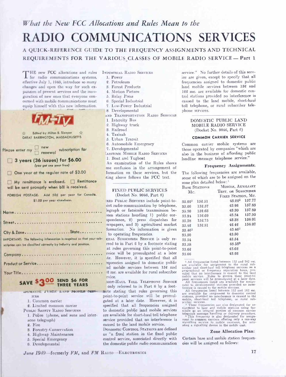
Frequency Assignments:
The following frequencies are available, some of which are to be assigned on the
below:1 MOBILE, AUXILIARY
TEST, OR SUBSCRIBER
FIXED STATION, MC.
zone plan detailed BASE STATIONS
MC.
35.222 152.51 43.222 157.77
35.26 152.57 43.26 157.83
35.30 152.63 43.30 157.89
35.34 152.69 43.34 157.95
35.38 152.75 43.38 158.01
35.42 152.81 42.42 158.07
35.462 43.462
35.50 43.50
35.54 43.54
35.58 43.583
35.62 43.62 35.66 43.66
1 All frequencies listed between 152 and 162 mc. are available for assignment to the rural sub- scriber and short -haul toll telephone services on a geographical or frequency separation basis, pro- vided that no interference is caused to the land mobile service. Rules to govern these point -to- point services will be promulgated at a later date.
All frequencies listed are available for assign- ment to developmental stations provided no inter- ference is caused to the mobile services.
All frequencies listed between 152 and 162 mc. are available for assignment to domestic control stations, provided no interference is caused to the mobile, short-haul toll telephone, or rural sub- scriber services.
2 These frequencies are also designated for as- signment to base and mobile stations using fac- simile as an integral portion of common carrier telegraph message handling or delivery procedure.
3 This frequency is also designated for assign- ment to common carriers offering only a one -way signalling service to mobile receivers, for actu- ating a signalling device in the mobile unit.
Zone Allocation Plan:
Certain base and mobile station frequen- cies will be assigned as follows:
17

performance of the receivers is included in the overall figures listed under trans- mitter characteristics.
Types of Antennas: It has been found that various antenna types are useful in meeting the problems encountered in remote pickup broadcast- ing. For the 160 -mc. band, a quarter - wave whip antenna is usually installed. This simple arrangement provides ex- cellent signals over the primary cover- age area and has the advantage of being permanently installed and capable of use while in motion. For extended coverage there is a three -element demountable array, Fig. 3, which weighs only a *few pounds, and can be erected quickly. The basic antenna is a coaxial type which can be used alone, or combined with a para- sitic reflector and director assembly to give a power gain of 4 over a half -wave dipole.
At the receiving location, a greater variety of antennas is available. For the permanently -installed receiver, a verti- cally polarized stacked array, giving a non -directional power gain of 4 times over a dipole, is generally used. Where the normal origin of pickup is in one gen- eral direction from the receiver, or when it is convenient to orient directional antennas for extended coverage, a 3 -ele- ment array with a power gain of 6 db over a dipole, and a 5- element array with a power gain of 9 db over a dipole are available. If the pickup receiver is used as a portable unit, a simple coaxial antenna is used ordinarily, because of its light weight and portability.
Fig. 7. This is a view beneath the chass
Various types of mobile, portable an( fixed antennas are being tested for 450 tc 470 me., but it is too early to form defi nite conclusions as to the types that wil prove most useful in mobile service a these frequencies. Those showing thy, greatest promise at the present time for general coverage are a coaxial J antenna for the transmitter, and vertically polarized, stacked arrays with power gains of 4 to 8 db for fixed or portably receivers. Yagi arrays with 10 db gait are effective for longer ranges and semi fixed pickups. These frequencies are con
sidered too low for parabolas.
---
Fig. 8. For portable use, the UHF remote pickup receiver is mounted in this manner
16
GROUP SUBSCRIPTIONS REMITTANCE MUST ACCOMPANY GROUP SUBSCRIPTIONS'
Two 1 -year subscriptions . . . $5.00 Three 1 -year subscriptions . . $6.00 Four 1 -year subscriptions . . . $7.00 Five 1 -year subscriptions . . $ 8.00 Six or more subscriptions, $1.60 per year each.
NAME New Sub. Renewal.
STREET
CITY & ZONE STATE
Company
Product or Service Your Title
New Sub.. NAME Renewal STREET
CITY & ZONE STATE
Company
Product or Service
Your Title
New Sub. NAME Renewal STREET
CITY & ZONE STATE
Company Product or Service
Your Title
New Sub NAME Renewal
STREET
CITY & ZONE STATE
Company
Product or Service
Your Title
other business to do while I was in Chicago for the Show. I wasn't able to get there when they would let me in, and when I had time free, they kept me out."
Because of the admission schedule, most manufacturers found it necessary to engage display rooms, in addition to their booths. Some found their show expense nearly doubled, because they had to take out enough men to handle both places. Also, the attendance was below the 1949 figure. This may have been due to the exclusion of servicemen.
FM AND TELEVISION

What the New FCC Allocations and Rules Mean to the
RADIO COMb1UNICATIONS SERVICES A QUICK- REFERENCE GUIDE TO THE FREQUENCY ASSIGNMENTS AND TECHNICAL
REQUIREMENTS FOR THE VARIOUS_CLASSES OF MOBILE RADIO SERVICE - Part 1
T11E new FCC allocations and rules for radio communications systems,
effective July 1, 1919, introduce so many changes and open the way for such ex- pansion of present services and the inau- guration of new ones that everyone con- cerned with mobile communications must equip himself with this new information. It is contained in the Federal Register of May 6, 1919, copies of which can be ordered from the Superintendent of Documents, Government Printing Office, Washington 25, D. C., at 20c.
You will find that a basic understand- ing of the 95 fine -print pages calls for many hours of serious study. To save your time, a thorough analysis of the allocations and rules is presented here. In this simplified form, you will be able to locate the essential information on any type of service. Then, you can use the full FCC text for more detailed in- formation. The following analysis is taken directly from the FCC Rules and Regulations. However, it must be em- phasized that this is only a short form of the full tee I . Every effort has been made to assure the accuracy of presen- tation, but further modifications may be made subsequently by the FCC.
The Service Classifications: Various existing types of communications services have been reclassified, and others have been added. It is necessary, there- fore, to understand the new major classi- fications, and the types of services grouped under each heading. As set up now, they are: FIXED PUBLIC SERVICES
1. Fixed Public x. Fixed Public Press 3. Agricultural 4. Rural Subscriber 5. Short -Haul Toll Telephone O. Domestic Control
DOMESTIC PUBLIC LAND MOBILE SERV-
ICES
1. Common carrier 2. Limited common carrier
PUnLIC SAFETY RADIO SERVICES
1. Police (phone, and zone and inter- zone telegraph) 2. Fire 3. Forest ry- Conserva t ion 4. Highway Maintenance 5. Special Emergency 6. Developmental
INDUSTRIAL RADIO SERVICES
1. Power 2. Petroleum 3. Forest Products 4. Motion Picture 5. Relay Press 6. Special Industrial 7. Low -Power Industrial 8. Developmental
LAND TRANSPORTATION RADIO SERVICES
1. Intercity Bus 2. Highway truck 3. Railroad 4. Taxicab 5. Urban Transit 6. Automobile Emergency 7. Developmental
MARITIME MOBILE RADIO SERVICES
1. Boat and Tugboat An examination of the Rules shows
some confusion in the arrangement of information on these services, but the listing above follows the FCC text.
FIXED PUBLIC SERVICES (Docket No. 9046, Part 6)
FIXED PUBLIC SERVICES include point -to- point radio communication by telephone, telegraph or facsimile transmission be- tween stations handling 1) public cor- respondence, 2) press dispatches for newspapers, and 3) agricultural market information. No information is given as to operating frequencies. RURAL SUBSCRIBER SERVICE is only re- ferred to in Part 6 by a footnote stating that rules governing this point -to -point service will be promulgated at a later date. However, it is specified that all frequencies assigned to domestic public land mobile services between 152 and 162 mc. are available for rural subscriber service. SHORT -HAUL TOLL TELEPHONE SERVICE
is only referred to in Part 6 by a foot- note stating that rules governing this point -to -point service will be promul- gated at a later date. However, it is specified that all frequencies assigned to domestic public land mobile services are available for short -haul toll telephone service provided that no interference is caused to the land mobile service. DOMESTIC CONTROL STATIONS are defined as "a fixed station in the fixed public control service, associated directly with the domestic public radio communication
June 1949- formerly FM, and FM RADIO -ELECTRONICS
service." No further details of this serv- ice are given, except to specify that all frequencies assigned to domestic public land mobile services between 152 and 162 mc. are available for domestic con- trol stations provided no interference is
caused to the land mobile, short -haul toll telephone, or rural subscriber tele- phone services.
DOMESTIC PUBLIC LAND MOBILE RADIO SERVICE
(Docket No. 9046, Part 6)
COMMON CARRIER SERVICE
Common carrier mobile systems are those operated by companies "which are also in the business of affording public landline message telephone service."
Frequency Assignments:
The following frequencies are available, some of which are to be assigned on the
below: I MOBILE, AUXILIARY
TEST, OR SUBSCRIBER
FIXED STATION, MC.
zone plan detailed BASE STATIONS
Mc.
35.222 152.51 43.222 157.77
35.26 152.57 43.26 157.83
35.30 152.63 43.30 157.89
35.34 152.69 43.34 157.95
35.38 152.75 43.38 158.01
35.42 152.81 42.42 158.07
35.462 43.462
35.50 43.50 35.54 43.54
35.58 43.583
35.62 43.62 35.66 43.66
All frequencies listed between 152 and 162 mc. are available for assignment to the rural sub- scriber and short -haul toll telephone services on a geographical or frequency separation basis, pro- vided that no interference is caused to the land mobile service. Rules to govern these point -to- point services will be promulgated at a later date.
All frequencies listed are available for assign- ment to developmental stations provided no inter- ference is caused to the mobile services.
All frequencies listed between 152 and 162 mc. are available for assignment to domestic control stations, provided no interference is caused to the mobile, short-haul toll telephone, or rural sub- scriber services.
s These frequencies are also designated for as- signment to base and mobile stations using fac- simile as an integral portion of common carrier telegraph message handling or delivery procedure.
s This frequency is also designated for assign- ment to common carriers offering only a one -way signalling service to mobile receivers, for actu- ating a signalling device in the mobile unit.
Zone Allocation Plan:
Certain base and mobile station frequen- cies will be assigned as follows:
17
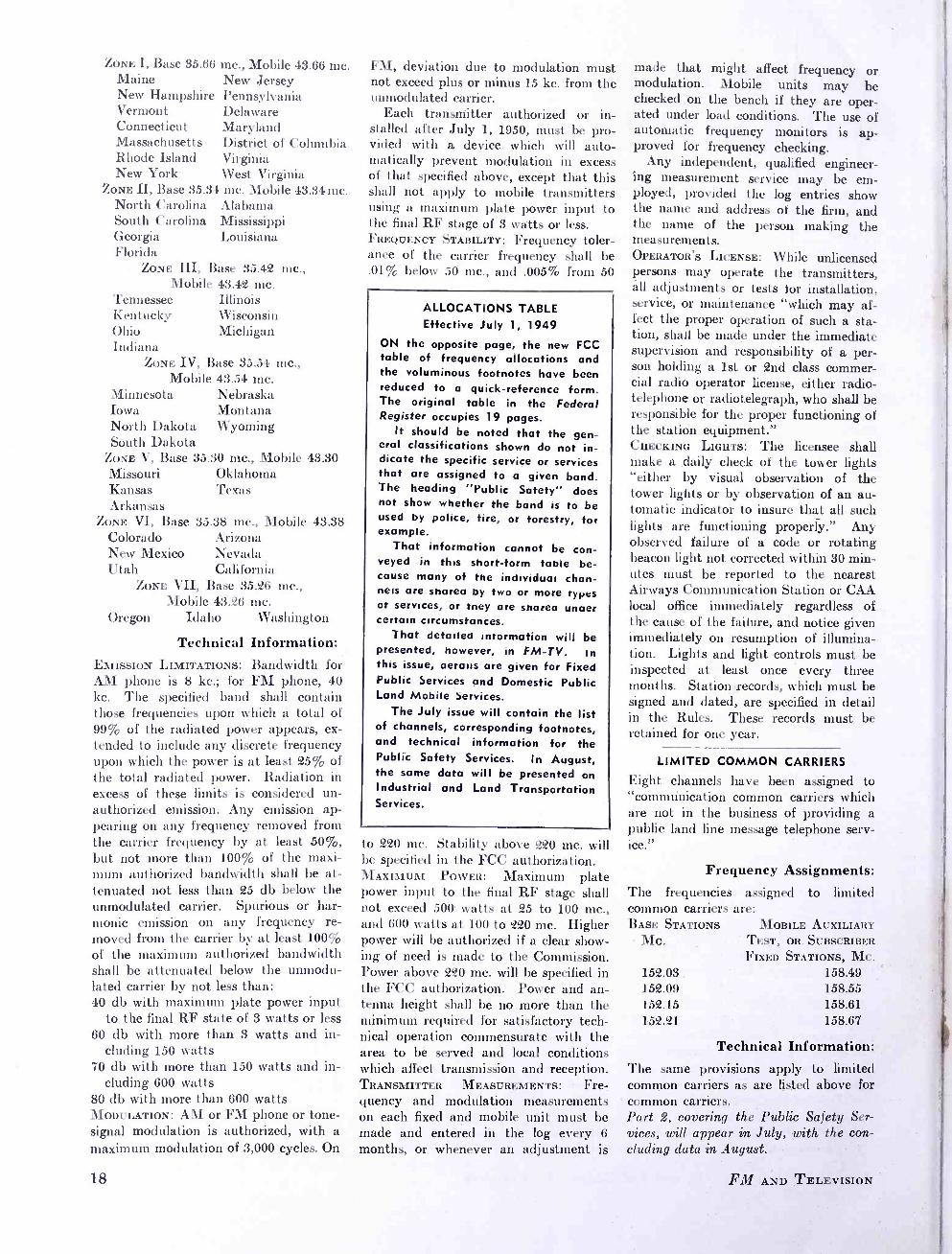
ZONE I, Base 35.66 Maine New Hampshire Vermont Connecticut
mc., Mobile 43.66 mc. New Jersey Pennsylvania Delaware Maryland
Massachusetts District of Columbia Rhode Island Virginia New York West Virginia
ZONE II, Base 35.34 mc. Mobile 43.34 mc. North Carolina Alabama South Carolina Mississippi Georgia Louisiana Florida
ZONE III, Base 35.42 mc., Mobile 43.42 mc.
Illinois Wisconsin Michigan
Tennessee Kentucky Ohio Indiana
ZONE IV, Base 35.54 mc., Mobile 43.54 mc.
Nebraska Montana Wyoming
Minnesota Iowa North Dakota South Dakota
ZONE V, Base 35.30 mc., Mobile 43.30 Missouri Oklahoma Kansas Texas Arkansas
ZONE VI, Base 35.38 mc., Mobile 43.38 Colorado New Mexico Utah
Arizona Nevada California
ZONE VII, Base 35.26 mc., Mobile 43.26 mc.
Oregon Idaho Washington
Technical Information: EMISSION LIMITATIONS: Bandwidth for AM phone is 8 kc.; for FM phone, 40 kc. The specified band shall contain those frequencies upon which a total of 99% of the radiated power appears, ex- tended to include any discrete frequency upon which the power is at least 25% of the total radiated power. Radiation in excess of these limits is considered un- authorized emission. Any emission ap- pearing on any frequency removed from the carrier frequency by at least 50%, but not more than 100% of the maxi- mum authorized bandwidth shall be at- tenuated not less than 25 db below the unmodulated carrier. Spurious or har- monic emission on any frequency re- moved from the carrier by at least 100% of the maximum authorized bandwidth shall be attenuated below the unmodu- lated carrier by not less than: 40 db with maximum plate power input
to the final RF state of 3 watts or less 60 db with more than 3 watts and in-
cluding 150 watts 70 db with more than 150 watts and in-
cluding 600 watts 80 db with more than 600 watts MODULATION: AM or FM phone or tone - signal modulation is authorized, with a maximum modulation of 3,000 cycles. On
18
FM, deviation due to modulation must not exceed plus or minus 15 kc. from the unmodulated carrier.
Each transmitter authorized or in- stalled after July 1, 1950, must be pro- vided with a device which will auto- matically prevent modulation in excess of that specified above, except that this shall not apply to mobile transmitters using a maximum plate power input to the final RF stage of 3 watts or less. FREQUENCY STABILITY: Frequency toler- ance of the carrier frequency shall be .01% below 50 mc., and .005% from 50
ALLOCATIONS TABLE Effective July 1, 1949
ON the opposite page, the new FCC table of frequency allocations and the voluminous footnotes have been reduced to a quick- reference form. The original table in the Federal Register occupies 19 pages.
It should be noted that the gen- eral classifications shown do not in- dicate the specific service or services that are assigned to a given band. The heading "Public Satety" does not show whether the band is to be used by police, fire, or forestry, for example.
That information cannot be con- veyed in this short -form table be- cause many of the individuai chan- nels are sharea by two or more types of services, or tney are sharea unaer certain circumstances.
That detailed information will be presented, however, in FM -TV. In this issue, aetauis are given for Fixed Public Services and Domestic Public Land Mobile Services.
The July issue will contain the list of channels, corresponding footnotes, and technical information for the Public Safety Services. In August, the same data will be presented on Industrial and Land Transportation Services.
to 220 mc. Stability above 220 mc. will be specified in the FCC authorization. MAXIMUM POWER: Maximum plate power input to the final RF stage shall not exceed 500 watts at 25 to 100 mc., and 600 watts at 100 to 220 mc. Higher power will be authorized if a clear show- ing of need is made to the Commission. Power above 220 mc. will be specified in the FCC authorization. Power and an- tenna height shall be no more than the minimum required for satisfactory tech- nical operation commensurate with the area to be served and local conditions which affect transmission and reception. TRANSMITTER MEASUREMENTS: Fre- quency and modulation measurements on each fixed and mobile unit must be made and entered in the log every 6
months, or whenever an adjustment is
made that might affect frequency or modulation. Mobile units may be checked on the bench if they are oper- ated under load conditions. The use of automatic frequency monitors is ap- proved for frequency checking.
Any independent, qualified engineer- ing measurement service may be em- ployed, provided the log entries show the name and address of the firm, and the name of the person making the measurements. OPERATOR'S LICENSE: While unlicensed persons may operate the transmitters, all adjustments or tests for installation, service, or maintenance "which may af- fect the proper operation of such a sta- tion, shall be made under the immediate supervision and responsibility of a per- son holding a 1st or 2nd class commer- cial radio operator license, either radio- telephone or radiotelegraph, who shall be responsible for the proper functioning of the station equipment." CHECKING LIGHTS: The licensee shall make a daily check of the tower lights "either by visual observation of the tower lights or by observation of an au- tomatic indicator to insure that all such lights are functioning properly." Any observed failure of a code or rotating beacon light not corrected within 30 min- utes must be reported to the nearest Airways Communication Station or CAA local office immediately regardless of the cause of the failure, and notice given immediately on resumption of illumina- tion. Lights and light controls must be inspected at least once every three months. Station records, which must be signed and dated, are specified in detail in the Rules. These records must be retained for one year.
LIMITED COMMON CARRIERS
Eight channels have been assigned to "commúnication common carriers which are not in the business of providing a public land line message telephone serv- ice."
Frequency Assignments: The frequencies assigned to limited common carriers are: BASE STATIONS MOBILE AUXILIARY
MC. TEST, OR. SUBSCRIBER
FIXED STATIONS, MC. 152.03. 158.49 152.09 158.55 152.15 158.61 152.21 158.67
Technical Information: The same provisions apply to limited common carriers as are listed above for common carriers. Part 2, covering the Public Safety Ser- vices, will appear in July, with the con- cluding data in August.
FM AND TELEVISION

FCC ALLOCATIONS Effective July 1, 1949
megacycles
INDUSTRIAL 25.01 -25.33 16 20 -kc. channels
GOVERNMENT 25.33 -25.85 INTL. BROADCASTING 25.85 -26.10 REMOTE BCST. PICKUP 26.10 -26.48
19 20 -kc. channels GOVERNMENT 26.48 -26.95 INTL. FIXED PUBLIC 26.95 -26.96
1 10 -kc. channel AMATEUR 26.96 -27.23 INDUSTRIAL, SCIENTIFIC MEDICAL EQUIPMENT' 27.12 EXPERIMENTAL 27.23 -27.28 INDUSTRIAL 27.28 -27.54
13 20 -kc. channels GOVERNMENT 27.54 -28.00 AMATEUR 28.00 -29.70 INDUSTRIAL 29.70 -29.80
5 20 -kc. channels AERO. FIXED - INTL. FIXED PUBLIC 29.80 -29.89
8 10 -kc. channels GOVERNMENT 29.89 -29.91 AERO. FIXED - INTL. FIXED PUBLIC
8 10 -kc. channels GOVERNMENT INDUSTRIAL
2 40 -kc. channels INDUSTRIAL - LAND TRANSPORT.
5 40 -kc. channels LAND TRANSPORT. PUBLIC SAFETY
8 40 -kc. channels PUBLIC SAFETY
21 40 -kc. channels GOVERNMENT PUBLIC SAFETY
3 40 -kc. channels INDUSTRIAL
7 40 -kc. channels PUBLIC SAFETY
15 40 -kc. channels GOVERNMENT INDUSTRIAL
1 40 -kc. channel INDUSTRIAL - MARITIME MOBILE
4 40 -kc. channels DOMESTIC PUBLIC LAND TRANSPORT
20 40 -kc. channels GOVERNMENT PUBLIC SAFETY
11 40 -kc. channels INDUSTRIAL
11 40 -kc. channels PUBLIC SAFETY
3 40 -kc. channels GOVERNMENT PUBLIC SAFETY
25 40 -kc. channels GOVERNMENT
INDUSTRIAL, SCIENTIFIC, MEDICAL EQUIPMENT' 40.68 PUBLIC SAFETY 42.00 -42.96
24 40 -kc. channels INDUSTRIAL 42.96 -43.00
1 40 -kc. channel INDUSTRIAL - MARITIME MOBILE 43.00 -43.20
5 40 -kc. channels DOMESTIC PUBLIC - LAND TRANSPORT 43.20 -44.00
20 40 -kc. channels LAND TRANSPORT. 44.00 -44.60
15 40 -kc. channels PUBLIC SAFETY 44.60 -47.68
77 40 -kc. channels INDUSTRIAL 47.68 -50.00
58 40 -kc. channels AMATEUR 50.00 -54.00 TELEVISION BCST. 54.00 -72.00
3 6 -mc. channels OPERATIONAL FIXED - (DOM. FIXED PUBLIC )3'1 72.00 -74.60
65 40 -kc. channels AERO. MARKER BEACON'' 74.60 -75.40 OPERATIONAL FIXED 75.40 -76.00
15 40 -kc. channels 29.91 -30.00 TELEVISION BCST. 76.00 -88.00
2 6 -mc. channels 30.00 -30.56 FM BCST.7 88.00- 108.00 30.56 -30.64 100 200 -kc. channels
AERO. LOCALIZER 108.00- 112.00 39 100 -kc. channels
AERO. RADIO RANGE 59 100 -kc. channels 112.00-118.00
AIRDROME CONTROL 33 100 -kc. channels 118.00- 121.40
AERO. MOBILE 121.40 -121.60 AERO. UTILITY 121.60- 122.00
2 200 -kc. channels PRIVATE AIRCRAFT 122.00- 123.00
5 200 -kc. channels FLIGHT TEST - FLYING SCHOOL 123.00- 123.60
3 200 -kc. channels AERO. MOBILE 123.60- 132.00
42 200 -kc. channels GOVERNMENT 132.00- 144.00 AERO. MOBILE' 140.58 AMATEUR 144.00- 148.00 GOVERNMENT 148.00- 152.00 DOMESTIC PUBLIC 152.00- 152.24
4 60 -kc. channels TAXICABS 152.24- 152.48
4 60 -kc. channels DOMESTIC PUBLIC 152.48- 152.84
6 60 -kc. channels INDUSTRIAL - ( REMOTE BCST. PICKUP) 9 152.84- 153.38
9 60 -kc. channels INDUSTRIAL 153.38- 153.74
6 60 -kc. channels PUBLIC SAFETY 153.74- 154.46
12 60 -kc. channels INDUSTRIAL 154.46- 154.62
2 80 -kc. channels
30.64 -30.84
30.84 -31.16
31.16 -32.00
32.00 -33.00 33.00 -33.12
33.12 -33.40
33.40 -34.00
34.00 -35.00 35.00 -35.04
35.04 -35.20
35.20 -36.00
36.00 -37.00 37.00 -37.44
37.44 -37.88
37.88 -38.00
38.00 -39.00 39.00 -40.00
40.00 -42.00
I Emissions from industrial, scientific, and medical equipment using the frequency 27.12 mc. must be confined to the band 26.96.27.28 mc.
2 Emissions from industrial, scientific and medical equipment using
the frequency 40.68 mc. must be confined to 40.66 -40.70 mc.
3 Operational fixed stations may be authorized to use frequencies in this band on the condition that harmful interference will not be caused to the reception of television stations on channels 4 or 5.
In any area in .the continental United States, the aviation service and marine service may each be authorized to use four of the
frequencies in the band 72 -76 mc. listed for operational fixed stations in these services.
4 Fixed stations in the domestic fixed public service may be author- ized to use any of the frequencies in the band 72 -76 mc. on the conditions that al harmful interference will not be caused to the reception of television stations on channels 4 or 5, and 61 that harmful interference will not be caused to operational fixed stations.
r' The frequency 75 mc. is designated for aeronautical marker
beacons. In Region 1, the guardband is ±0.2 mc; in Regions 2 and
3, ±0.4 mc,
6The use of the frequency 75 mc. by aeronautical marker beacons is temporary and may be authorized until they are moved to a
frequency band allocated for the aeronautical radionavigation service, or until they are no longer required.
r Facsimile broadcast may be authorized in the band 88 -108 mc.
8 The frequency 140.58 mc. may be authorized on an interim basis
to civil aviation as a common simplex frequency for emergency and distress communications, available to all stations operating in
or with the aeronautical mobile service. 0 The use of the frequencies in the block 152.87-153.35 mc. may be
authorized, in any area, to remote pickup broadcast base and mobile stations on the condition that harmful interference will not be caused to the industrial radio services.
PUBLIC SAFETY 154.62- 156.25 27 60 -kc. channels
MARITIME MOBILE - ( PUB. SAFETY )10'11'12 156.25- 157.15
9 100 -kc. channels GOVERNMENT 157.15- 157.35 MARITIME MOBILE - ( PUBLIC SAFETY) 157.35- 157.45
1 10 -kc. channel TAXICABS 157.45- 157.74
4 60 -kc. channels DOMESTIC PUBLIC 157.74- 158.10
6 60 -kc. channels INDUSTRIAL 158.10- 158.46
6 60 -kc. channels DOMESTIC PUBLIC 158.46- 158.70
4 60 -kc. channels PUBLIC SAFETY 158.70- 159.48
13 60 -kc. channels LAND TRANSPORT - ( PUBLIC SAFETY )13 159.48- 161.85
39 60 -kc. channels MARITIME MOBILE COAST 161.85- 162.00
2 channels: ( 161.9 & )1°'14
GOVERNMENT'''16 162.00- 174.00 ( REMOTE BCST. PICKUP)' TELEVISION BCST.
7 6 -mc. channels GOVT. TELEMETER'G AMATEUR GOVERNMENT AERO. GLIDE PATH GOVERNMENT RADIOSONDE GOVERNMENT AMATEUR REMOTE BCST. PICKUP
20 100 -kc. channels LAND TRANSPORT
20 100 -kc. channels PUBLIC SAFETY 454.00- 456.00
20 100 -kc. channels INDUSTRIAL 456.00- 458.00
20 100 -kc. channels DOMESTIC PUBLIC 458.00- 460.00
20 100 -kc. channels CITIZENS RADIO 460.00- 470.00 FACSIMILE BCST. 470.00- 475.00 BROADCASTING 475.00 -500.00 TELEVISION BCST. 500.00- 890.00 BROADCASTING 890.00- 940.00 INDUSTRIAL SCIENTIFIC, MEDICAL EQUIPMENT 915.00 FM BCST. S -T LINK'S 940.00- 952.00 INTL. CONTROL - OPERATIONAL FIXED 952.00- 960.00 AERO. NAVIGATION 960.00 -1,215 AMATEUR 1,215 -1,300 SURVEILLANCE RADAR 1,300 -1,365 AERO. NAVIGATION 1,365 -1,660 RADIOSONDE 1,660 -1,700 GOVERNMENT 1,700 -1,850 INTL. CONTROL - OPERATIONAL FIXED 1,850 -1,990
174.00- 216.00
216.00- 220.00 220.00- 225.00 225.00- 328.60 328.60- 335.40 335.40- 400.00 400.00- 406.00 406.00- 420.00 420.00- 450.00
450.00- 452.00
452.00- 454.00
10 The use of the frequencies 156.27, 156.33, 156.39, 156.45, 156.51, 156.57, 156.63, 156.69, 156.75, 156.87, 156.93, 156.99, 157.05, 157.11, 157.41, 157.47, 161.85, 161.91 and 161.97 mc. may be authorized to base and land mobile stations in the public safety radio services on the condition that no harmful interference will be caused to the maritime mobile service. Public safety service operations at points within 150 miles of coastal areas and navigable gulf, bays, rivers and lakes, may be authorized only after a factual finding indicates that, on an engineering basis, no harmful interference will be caused to the maritime mobile service. 11 The international port operational service, on a simplex basis, has priority on this frequency. 12 The frequency 156.80 mc. has been designated for world -wide use for safety, calling and intership and harbor control communica- tions in the maritime mobile service. 13 The use of the frequencies in the block 159.51- 161.79 mc. may be
authorized to base and land mobile stations in the public safety radio services, in any area, on the condition that harmful inter- ference will not be caused to stations in the railroad radio service.
54 In the Chicago area, only the frequencies 161.85 mc. and 161.91
mc. may be authorized to base and land mobile stations only for train communications in the railroad radio service.
16 The government frequencies, 170.425, 170.475, 170.575, 171.425, 171.475, 171.575, 172.225, 172.275, and 172.375 mc. may be author- ized to fixed, land and mobile stations owned and operated by non -Federal forest fire fighting agencies, in certain areas, on the
condition that no harmful interference will be caused to any government stations. 16 ln order to provide for inter -communication for safety purposes between government and non -government stations in the maritime mobile service, the frequencies 157.2 and 157.3 mc. are allocated exclusively in all areas, to government stations in the fixed and mobile services, and the frequencies 173.225, 173.275, 173.325, 173.375 mc. are allocated exclusively, in all areas, to non- govern- ment stations in the fixed and land mobile services.
TV PICKUP - TV S -T LINK'S 1,990 -2,110 INTL. CONTROL - OPERATIONAL FIXED 2,110 -2,200 GOVERNMENT 2,200 -2,300 AMATEUR 2,300 -2,450 NON -GOVT. FIXED &
MOBILE 2,450 -2,500 INTL. CONTROL - OPERATIONAL FIXED 2,500 -2,700 AFRO. NAVIGATION METEOR- OLOGICAL AIDS 2,700 -2,900 NAVIGATION 2,900 -3,246 RACON 3,246 -3,266 NAVIGATION 3,266 -3,300 AMATEUR 3,300 -3,500 NON -GOVT. FIXED &
MOBILE 3,500 -3,700 COMMON CARRIER FIXED 3,700 -4,200 ALTIMETER 4,200 -4,400 GOVERNMENT 4,400 -5,000 AFRO. NAVIGATION 5,000 -5,250 NAVIGATION 5,250 -5,440 RACON 5,440 -5,460 NAVIGATION 5,460 -5,650 AMATEUR 5,650 -5,925 INDUSTRIAL, SCIENTIFIC, MEDICAL EQUIPMENT 5,850 COMMON CARRIER FIXED 5,925 -6,425 NON -GOVT. FIXED &
MOBILE 6,425 -6,575 INTL. CONTROL - OPERATIONAL FIXED 6,575 -6,875 TV PICKUP - TV S -T LINK 6,875 -7,125 GOVERNMENT 7,125 -8,500 NAVIGATION 8,500 -9,800 NON -GOVT. FIXED 9,800 -9,900 GOVERNMENT 9,900- 10,000 AMATEUR 10,000 -10,500 INDUSTRIAL, SCIENTIFIC, MEDICAL EQUIPMENT70
10,500- 10,700 COMMON CARRIER FIXED 10,700 -11,700 NON -GOVT. FIXED &
MOBILE 11,700- 12,200 INTL. CONTROL - OPERATIONAL FIXED 12,200- 12,700 TV PICKUP - TV S -T LINK 12,700- 13,200 GOVERNMENT 13,200- 16,000 NON -GOVT. FIXED &
MOBILE 16,000- 18,000 INDUSTRIAL, SCIENTIFIC, MEDICAL EQUIPMENT'-'
GOVERNMENT AMATEUR GOVERNMENT NON -GOVT. FIXED &
MOBILE EXPERIMENTAL - AMATEUR
18,000 18,000- 21,000 21,000- 22,000 22,000- 26,000
26,000- 30,000
30,000 Upward
17 The use of the frequencies 166.250 and 170.150 mc. may be auth- orized to non -government remote pickup broadcast base and land mobile stations and to non -government base fixed and land mobile stations in the public safety radio services (the sum of the band width of emission and tolerance not to exceed 60 Kc.l in
Continental U. S. only, except within the area bounded on the west by the Mississippi River, on the north by the parallel of latitude 37° 30' N., and on the east and south by that arc of the circle with center at Sprinafield, Ill., and radius equal to the airline distance between Springfield, Ill., and Montgomery, Ala., sub- tended between the foregoing west and north boundaries, on the condition that harmful interference will not be caused to govern- ment stations present or future in the government band 162.174 mc. The use of these frequencies by remote pickup broadcast stations will not be authorized for locations within 150 miles of New York City; and the use of these frequencies by the public safety radio services will not be authorized for locations within 150 miles of New York City.
"Interim FM relay stations may be authorized to use the band 940 -952 mc. on the condition that harmfu I interference will not be caused to stations operating in accordance with the table of fre- quency allocations. 59 Interim television relay stations may be authorized to use fre- quencies in this band on the condition that harmful interference will not be caused to stations operating in accordance with the table of frequency allocations.
20 Emissions from industrial, scientific and medical equipment using the frequency 10,600 mc. must be confined to the band 10,500- 10,700 mc. Sharing by radio -communication services is to be determined at a later date.
xi Emissions from industrial, scientific and medical equipment using the frequency 18,000 mc. must be confined to the band 17,850- 18,150 mc. Radiocommunication services operating within the band 17,850- 18,150 mc. must accept any harmful interference that may be experienced from the operation of industrial, scientific and medical equipment.

20
meets the challenge!
announces the new "RESEARCH LINE"
solves th :ADJACENT CHANNEL PROBLEM
Today! The modern, the scientific, the ideal mobile radio communications equipment is here. Research, experimentation, development, and field testing in systems operation produced this scientific answer to the adjacent channel operations problem. The minor problem of super- precision selectiv- ity was solved in six months, but two years of research and the creation of five major inven- tions were required to solve the major problem of intermodulation before same -area adjacent channel operation became practicable. Here is equipment that is new all through, with the new amazing circuit inventions which pro - vide a new standard of performance for the industry. Here is equipment to give you the most mod- em communications system you can own -ac- tually anticipating the standards of good en- gineering practice for the future. This startling departure from the conventional, offering new simplicity of maintenance, and a new standard of reliability -this engineering anti scientific achievement is the new MOTOROLA "Research Line ":
FM AND TELEVISION

th "n
esen t;R leiVelaas I).JACENT CHANNEL
OPERATIONS - ra c tcabl
nventions make
SENSICON CIRCUIT (PAT. PENDING;
ISO -0 CAVITIES (PAT. PENDING)
STATOMIC OSCILLATOR !PAT. PENDING)
PERMAKAY FILTER (PAT. PENDING)
BRIDGE BALANCED OVEN (PAT. PENDING,
CAPACITANCE DISCRIMINATOR (U.S. PAT. 2,404,359)
DIFFERENTIAL SQUELCH (U. S. PAT. 2,343,115;
I. D. C. SLOPE FILTER (PAT. PENDING,
The Sensicon Circuit A radical departure from con- ventional receiver design to achieve control of intermodula- lion, the major barrier to suc- cessful adjacent channel opera- tion. The Sensicon Circuit is the name given to the practicable embodiment of an invention which will change profoundly all future communication re- ceiver design. The Sensicon Cir- cuit is a MOTOROLA "first" (Patents Pending),
I.D.C. Consider the Sensicon Circuit, the Permakay Filter, the Sta- tomic Oscillator, and the Iso -Q Cavities, and then add to all these the Instantaneous Devia- tion Control (Patent Pending) to keep the modulated trans- mitter radiation within the channel boundaries and you have the formula which an- swers the adjacent channel problem. Not one, but all of these inventions are necessary for practicable, trouble -free systems operation.
The Permakay Filter The super- precision selectivity of the Sensicon receivers, 100 db. down at the edge of the adjacent channel, is achieved by the Permakay Filter (Patent Pending). Cast in a solid block of polyester styrene, sealed against moisture, vibration and change, this unit is guaranteed for the life of the equipment.
The Statomic Oscillator Single -cycle frequency control provided by the stable auto- matically compensated crystal circuit, stops drift and holds the signal perfectly.
ISO -Q Cavities Silver plated, sealed, thermally compensated Iso -Q Receiver Cavities (Patent Pending) freeze the selection of the desired sig- nal.
Remember! Selectivity alone is not the answer to adjacent channel operation. The integrated systems combination of these new inventions is the modern engineering answer to full channel utilization.
i
the BEST is B ETT ER
before .. . than ever be[
With any other feature for feature COM_
PARE market ... GET THE O
eq Pm TORY the THIS COUPON TO
pLETE S
¡AID> Ar.
FM 2 -WAY RADIO
June 1949-formerly FM, and FM RADIO -ELECTRONICS
MOTOROLA INC., Communications Division 4545 Augusta Blvd., Chicago, III. Dept. FM &T Jun
Name
Position
Firm
Address
City Zone State
21

SPOT NESS NOTES COMMENTS SIGNIFI- CANT ACTIVITIES OF PEOPLE & COMPANIES
"Ile's a corn)), linleations engineer, sir. . .
Been like this since May 6, 1949"
FCC Opens TV Ice Box: Official announcement issued on May 26 promises a TV plan providing a "nation- wide assignment plan covering commer- cial operation in both [VHF and UHF] bands." This will include a "substantial" number of VHF authorizations, plus 6- mc. channels in "approximately one -half of the lower portion of the UHF band," the balance being kept open for research on "stratovision, polycasting, and high - definition monochrome and color." Com- plete text of the FCC announcement will be found in What's New This Month, of this issue.
Give -Away Programs: They will collapse, one of these days, from sheer weight of their gargantuan proportions. When they do, sponsors and listeners will discover to what an extent they have crowded out genuine entertainment. Any third -rate adver- tising agency can handle them without using brain -power above the copy -boy level. They represent the shoddiest effort on the part of the producer, and the lowest grade of program material. As such, they are of no credit to the sponsor or to radio broadcasting.
TV Picture Size: The practice of rating TV pictures in square inches is misleading to the point of justifying an investigation by the FTC or the BBB. The number of square inches claimed for a given picture -tube diameter now runs from that obtained with a rectangle of standard RMA 3 -to -4 aspect ratio with or without the corners cut off, to the total area of the tube face.
22
Thus, it is impossible to relate picture area in square inches to the size of the tube with which a set is equipped.
Report on the FCC: Everyone in the industry should read Senator Edwin C. Johnson's speech of April 20, when he discussed the problems of broadcasting, and the manner in which they are being handled by the FCC. It's a masterful, non -partisan presentation. If you haven't read it, get a copy, by all means. Reprints are available without charge from the FM Association, 526 DuPont Circle Building, Washington 6, D. C.
TV Operation on UHF: NBC has been authorized to operate an experimental station at Bridgeport, Conn., on a frequency in the neighbor- hood of 500 mc. Transmitter will prob- ably have 1 kw. output, with a high antenna gain. It is expected that RCA will produce suitable receivers.
Help for Communications: After wading through the 95 pages of the Federal Register required to print the revised allocations, rules, and regula- tions on mobile communications, we are prepared to agree with Jeremiah Court- ney's remarks published in our previous issue. Operators of communications sys- tems certainly are going to need legal and engineering counsel. We can't even figure out how the consultants can under- stand what FCC means in some cases.
TV Microwave Relay Design: It has been standard practice to mount the microwave relay transmitter or re- ceiver unit directly behind the antenna dish. On permanent, outdoor installa- tions, exposure to the weather has dis- advantages. The New York Telephone Compány uses a different arrangement. They mount the microwave unit within the building, and run up to 30 ft. of 2- by 1 -in. Titeflex flexible waveguide to the outdoor antenna. Attenuation in the waveguide is rated at less than .05 db per foot.
Transitcasting in Boston Area: WLYN -FM, at Lynn, Mass., is furnish- ing programs for 300 buses operated by the Eastern Massachusetts Street Rail- way Company in Medford, Malden, Lynn, and Salem. Station manager is A. M, Morgan.
Tests of FM vs. AM for TV: Prewar tests conducted by RMA's Na- tional Television System Committee are
quoted frequently to show that FM has been found inferior to AM for picture - signal transmission. Text of the report appears on page 260 in "Television Standards and Practice" (McGraw -Hill) .
What seems to be forgotten is the fact that, according to the report: "No FM limiter was used." What the report does not state is that the receiver employed was an AM model! It was on the basis óf such a test that NTSC decided: "The contrast between the two systems was very marked, and decidedly in favor of FM." FCC engineers are currently check- ing FM vs. AM for video, and have ob- tained encouraging results on FM.
Future of FM Broadcasting: Pros and cons of FM's future have been argued hotly of late. Fact is that video broadcasting has an advantage in point - of -sale appeal because it offers a com- pletely new and novel feature as com- pelling as reception of audio programs back in 1920. Then, the fact of hearing something was more important than what was heard. Now, the fact of seeing something, is more important than what is seen. But it won't be long until pro- grams will be as important on TV as they are now on FM. Then, the two services will compete on an even footing. Not arguments but programs and pro- motion will give us the answer.
CBS Lists No FM Affiliates: In the annual report to CBS stock- holders, 179 owned and affiliated AM stations are listed, but there is nothing to show that any of these operate FM transmitters. Seems surprising, for the only way many listeners can hear CBS programs is on FM.
Radio's Customer, Too: We've always admired the realistic at- titude of Bell Telephone Laboratories to- ward the business of giving telephone users what they want. Particularly, we like the caption in current Bell Labs advertising: "The Ear Is Our Customer." We thought of that when, on May 15, we snapped off the Lucky Strike pro- gram. We don't remember the exact part when there was so much yelling and confusion, but we do remember our annoyance at the sponsor, Jack Benny, and the whole program staff for presum- ing to think that they were entertaining us by making such an infernal racket come out of our loudspeaker. Maybe its just blind faith, but we still hope to see the day when both broadcasters and set manufacturers discover that the ear is the radio industry's customer, too.
FM AND TELEVISION

1. !t'OR-TV moves toward completion
NEWS PICTURES 1. With WOR -TV shaping up as the tele- vision show -place for New York visitors, Jack Poppele, third from left, as engi- neering vice president for WOR, and as- sistant chief engineer Charles Singer, left, have made this their pet project. Paul Chamberlain and Grady Rourke of G. E. are in there pitching, too.
2. John Sherman, technical director of WTCN Minneapolis, says his station holds the record for antennas on a broad- cast tower. They are for 1) high -power FM on 97.1 mc.; 2) high -power video; and 3) audio for TV on channel 4; 4)
mobile FM remote pick -up transmitter or 153.53 mc., and 5) AM talk -back and
Ñ. Seven antennas on WTCN torcer 3. TV engineers from Brazil, Cuba, Italy
cue circuits and, finally, 6) two parabolas for the mobile TV unit on 6,950 mc.
3. Fifteen engineers from foreign coun- tries attended RCA's recent TV training program. Among them were, left to right. W. Obermiller, Brazil; V. Montes and Antonio Zamarano, Cuba, and Dr. Edoardo Cristo Faro, Italy.
4 Jewel Store manager Roy Martin and James Hyde, of Consumers Aid, help WMOR manager Ralph Wood check store speakers in preparation for starting FM music service for the Jewel chain.
5. During the convention of the Amer- ican Wood Preservers Association, St. Louis station KSD -TV sent its mobile
unit into the Monsanto Chemical plant where chemists demonstrated the use of various equipment and processes.
6. In Providence, R. I., the Journal - Bulletin has created tremendous listener interest with public- service features from its FM station WPJB. Here, publisher Servellon Brown presents scholarships to music contest winners Joyce Mangler, Martha Butler, John R. Pandolfi, and a certificate to Jean Porter.
7. CBS is using tiny induction telephone units developed by Link Radio, for TV studio communication. They provide 2
channels on 100 to 175 kc. Use of three subminiature tubes keeps total weight to 21/4 lbs.
4. Storecasting readied in Chicago 5. TV cameras tour factory 6. WPJB awards scholarships 7. Radio for TV studios

TV OPERATION IN SMALL CITIES DESCRIBING THE EQUIPMENT LAYOUT AND OPERATION FOR A COMMERCIALLY PRACTICAL, MINIMUM -COST SECONDARY TV INSTALLATION -By E. J. MEEHAN*
EARLY in 1949, with the inception of coaxial interconnecting service be-
tween the eastern seaboard and the mid - west, network -fed, low -power television stations became a practical, commercial reality. The impact of the situation thus created has provoked a need for "second- ary stations" to make network programs available in the smaller cities.
Secondary stations, as defined by FCC Chairman Coy in his address at the NAB convention last spring, "must be simple in construction and operation, to give minimum investment and operating cost. The stations must be, as nearly as possible, automatic in operation, thus re- quiring a minimum staff." To meet the need for a practical low -cost, minimum operation, RCA has worked out a new overall plan for such an installation, capable of handling both network and film programs.
Essential Operating Functions: The accompanying illustrations show a
suggested layout for a secondary station, and the equipment necessary. The prime requisite is that such an operation be workable from the economic point of view. To this end, specific items of equipment has been selected to make up what we call the Basic Buy.
* Engineering Products Department, Radio Cor- poration of America, Camden, N. J.
Fig. 1. Model of a TV station equipped with the units comprising RCA's Basic Buy To make the proper selection of equip- ment, and to plan its arrangement to best advantage, it is important to under- stand the four separate functions to be performed in the operation of a second- ary station. These are:
1. TRANSMITTER CONTROL requires transmitter monitoring, maintaining proper levels of sync and modulation, and responsibility for getting the cleanest picture from the incoming network through proper use of the stabilizing amplifier. Maintenance of the proper
Fig. 2. Floor plan of the transmitter building, laid out for simplicity of operation
ANNOUNCE BOOTH 1ÓX 14
DOUBLE GLASS
MONITOR
DESK
PROJECTION ROOM 16.X 14
ir FUTURE RACK
L____., LOCATION
MULTIPLEXER 6 SLIDE PROD.
FUTURE 16MM PROJ.1 i n LOCATION L ___J ¡
FILM CAMERA CONTROL J FILM
CAMERA
16M M PROJ.
DOUBLE GLASS
1 DOUBLE GLASS
2
CONTROL CONSOLE
3 RACK EOUIPMT
4 XMTR
5
CONTROL ROOM 37'X 16'
24
level of sound transmission is also a func- tion of transmitter control.
2. PROGRAM SWITCHING involves the selection of proper picture and sound channels, previewing programs before their transmission, cueing film and trans- mitter operation and switching, and fading and superimposing video and audio signals being fed into the trans- mitter control. Operation of turntables also falls in this operation.
3. FILM CONTROL is that function which is charged with responsibility for maintaining proper shading of the pic- ture output of the film camera. Most motion picture film varies greatly in average picture brightness from one scene to another, and it is essential that continuous monitoring and shading be performed during film transmission.
4. FILM PROJECTION calls for the proper operation and feeding of the tele- vision film projector, and correct sequen- tial feeding of slides to the slide projector. This operation also involves pre -running all film, timing film pro- grams, and adjustment of optical equip- ment.
It is possible, and quite likely in many operations, for several of these technical functions, together with that of announc- ing, to be combined in various methods. The relation between types of program being shown, degree of personnel train- ing, cost, local regulations, and other fac- tors all contribute to the particular re- quirements of each individual operation.
Certain operating functions lend them- selves to combination with others in this system, due to physical and operational
FM AND TELEVISION

RACK Na1 RACK Nat PACK Nei RACK No.4 RACK Ne.5
WP33 B FOR
PREVIEW MON.
METER PANEL METER PANEL 580 C FOR
MONOSCOPE
STUDIO SYNC
GENERATOR
F M FREQ. 8 MOD. MON.
WP33 B FOR
XMTR CONSOLE MON
MONOSCOPE
580 C FOR
DIST. AMP Nei M IX AMP.Ne.2
STAB. AMP. No I 16MM SOUND EGL.
BA-13A Ne.1 8 2 580 C FOR
STAB. AMP No.1 MIX. AMP. Ne.2
VID. JACK PANEL 1
86-AI LIMITING AMP
MIX. 'AMR Na I
AUD. JACK PANEL I MIX. AMR Ne. 2
BA -IA Ne.1,28 3 AND BX-ID
AUD.JACK PANEL 2 VID. JACK PANEL 2 24v. POWER SUPV
PRE -EMP. NET. BLANK
BLANK POWER SUPPLY
FOR MI- 30012 -A 8. M1 -30013 -A
BLANK
SPACE FOR FUTURE
STAB. AMR.
SPACE FOR FUTURE
580 C POWER SUPY
WP 33 B FOR
FILM CHAIN
BA -4C MONITORING AMR
FREQ. METER W F-49 A
OUTLET PANEL FREQMON. WF-50 A
57C SWITCH 8 FUSE PANEL WP33 B
FOR FILM CHAIN
CIRCUIT BREAKER
PANEL
57 C SWITCH 8 FUSE PANEL
BLANK BLANK
TURN- TABLE
RACK LAYOUT
XMTR MON
PRE -VU MON
XMTR CONTROL TURRET
PROGRAM SWITCHING
TURRET
CONSOLE LAYOUT
Fig. 3. Details of the equipment carried
proximity. Transmitter control and pro- gram switching are both performed at a combination console and, except in operations where close program timing and equipment supervision is desired, may usually be performed by one versa- tile operator.
Film control and film projection are
Fig. 4. The video and audio transmitter
in the five racks and in the control console
performed in the film projection room and, to some degree, can be paired or combined, again depending on local circumstances. For an all-film operation, greater requirements would be placed, for example, on film personnel, while the program switching function would be correspondingly simplified.
It is felt, however, that whatever corn - bination of functions be assigned to in- dividual operating personnel, it is desir- able, due to the variety of applications for this type of layout, that each princi- pal function be separated for the pur- poses of this discussion.
Transmitter Building Plan: The model photographed in Fig. 1, and the floor plan in Fig. 2 show how facili- ties enumerated above are provided in combination with a type TT -500 tele- vision transmitter. In addition to the main transmitter -control room there is a film projection room at the rear right, an announce booth where a camera can be set up for interviews, and auxiliary space at the left for power equipment, storage, and a maintenance shop.
Equipment in the transmitter -control room comprises the transmitter, at the left, ceiling- mounted vestigial sideband filter, diplexer, input, and monitoring units, the console combination and turn- tables, and five racks carrying the video and audio power, and equalization. stabilization, and distribution circuits.
Ample space is provided in the floor area 37 by 16 ft. Utmost personnel effic- iency is afforded, since one operator at the console can attend the transmitter and perform the necessary program switching, at the same time maintaining
June 1949 -formerly FM, and FM RADIO -ELECTRONICS
proper sound and picture levels. He also commands a view of the announce booth and film projection room, which facili- tates cueing and program coordination.
The individual items of equipment and their functions are described in detail in the sections which follow, with a basic diagram of the complete installation in Fig. 3.
Television Transmitter: The transmitter, Figs. 4 and 5, provides an output from the sideband filter of 500 watts for the picture and 250 watts for the sound. Effective radiated power de- pends, of course, on the antenna, which may have a gain of up to approxi- mately 7.2. A 6- section superturnstile, for example, would provide radiation of 3.6 kw. on the picture signals. Dimen- sions of the transmitter cabinet are 84 ins. high, 56 ins. wide, and 31 ins. deep.
Film Chain and Facilities: A 16-min. television film projector, with film multiplexer, slide projector, and film camera chain, together with control equipment and monitor, are located in the film projector room. A standard tele- vision receiver with de- sensitized input, operating directly off the air, enables the projectionist to obtain accurate cueing.
This station plan was designed pri- marily for film- network operation. The availability of live video signals for net- work programming, while desirable, is not essential. Network kinephoto serv- ice is now available in quantity and may,
Fig. 5. Interior of the 500 -watt design

NETS INPUT
580 C POWER SUPPLY
P
ALL UNITS WITHIN DOTTED BRIDGED' T NETWORKS LINES ARE LOCATED IN I
TC20A PGR14 SWITCHING TURRET
5
r - - -, 118MM
PROD.
1FUTURE MULTIPLEXER I 5 SLIDE PROD.
18MM PROJ.
FILM CAMERA
V
STAB AMP. Ne.1
WP33B POWER SUPPLY
WP33B POWER SUPPLY
Ie MASTER MONITOR
FILM CAMERA
CONTROL
PIC OUT
VS
VS
MON. OUT
V
580 C
POWER
PULSE
1
SUPPLY DR
DIST P
BOX
-1 I- FI LM RM MONITOR
RECVR
"DR MONOSWPE
R
MIX. AMP. Ne.1
VS
M IX.
AMP Ne.2
STUDIO SYNC GEN.
580 C POWER SUPPLY
--4
PGM SWITCHES
I I
I
-- >
AUDIO JACK PANEL Ne.1
STAB.AMP. Net MON. OUT -c SWITCHING TURRET PREVIEW INPUTS
MIXING AMP. Net OUT -< MIXING AMP. Ne 1 OUT
SWITCHING TURRET PICTURE INPUTS -( Y-
STAB.AMP. Ne.1 PIC OUT -C NETWORK -C )- STAB. AMP. Net PIC INPUT
MONOSCOPE PIC OUT > MIXING AMP Net INPUT FILM CAMERA OUT r- MIXING AMP No 1 INPUT
-<
DIST. AMP. NoI E D C B A
WP33B POWER SUPPLY
PREVIEW MONITOR
VIDEO FUNCTIONAL DIAGRAM
PREVIEW SWITCHES J
C
XMTX INPUT
XMTR MON. INPUT
ANNCE BOOTH
MON. REC.
I ANNE I BOOTH
MIC.pf)
L .1
NETWORK INPUT
rPROJ. ROOM I
16 MM PROD.
70 D
T.T. Ne.1
70 D T Ne.2
"i 16 MM
EOl1ZER
- PRE - DAR
NET. -r___f AI XMTR
TC -20A PROGRAM SWITCHING PROGRAM SWITCHES
TURRET
AUDITION SWITCHES
PROGRAM
AUDITION
LC-IA LOUD SPKR
P DR S V
VS <-> 1:1.
POWER DRIVING E BLANKING SYNC VIDEO VIDEO 6 SYNC. COAXIAL JACKS TERMINATION
PHOaNES
_ _ J UNITS WITHIN DOTTED LINES
ARE IN XMTR CONTROL CONSOLE
1Ì1 \.% Y `
L_
l
MON. I
GAIN I
BA-C
I
J
MIC. OUT
T.T. Nel OUT
T.T.Ne2 BA -IA OUT 1 OUT
NET 16 MM LINE COL OUT
BA -IA BA-1A 2 OUT 3 OUT
TC -20A TC -20A PGM. OUT AUD.OUT
BA -13A BA -13A 1 OUT 2OUT
BA-1A Ne.1 IN
BA-IA Ne. 21N
BA-1A Ne.3 IN
TC-20A I TC -20A INPUT 1 INPUT 2
TC-20A INPUT 3
TC -20A INPUT 4
TC-2OA INPUT 5
BA-13A Ne.11N
BA -13A LINE TO Nó.2 IN NIEEIIINET
MON.CHnI SW.IN I
AUDIO FUNCTIONAL DIAGRAM
i
Fig. 6. Functional diagrams of the audio and video controls and switching facilities which are provided in the control console
in large measure, be substituted for live network in areas where such facilities are not available. Operation of this type would consist initially of film program- ming entirely.
For this reason, space has been pro- vided for the addition of a second 16- mm. television film projector, which would be necessary to maintain contin- uous programming with this system. Re- cent improvements in the quantity and quality of off- the -kinescope film serve to emphasize the significance of this type of programming, and the increasing role it must play in small TV station operation.
The film camera control unit contains all operating controls for the film camera. Used in conjunction with a 10 -in. picture monitor and a 5 -in. waveform 'scope, it enables the operator to adjust and main- tain within close tolerance the quality and level of the picture produced. The camera control is mounted in a standard console section which matches the other .equipment.
A separate projection room, as shown in Figs. 1 and 2, is recommended for the control unit. The camera control moni- tor will then provide the projectionist with a means of monitoring the output -of his film camera constantly.
Announce Booth:
For local news, commercials, and station breaks, an announce booth is provided.
26
Equipment in this booth consists of an- other de- sensitized off- the -air receiver for monitoring purposes, a microphone, and a loudspeaker. The television re- ceiver enables the announcer to coordi- nate his announcements with the trans- mitted picture.
Switching Equipment: The switching section of the combina- tion console, Fig. 6, utilizes rack mounted equipment for audio and video amplification and distribution, plus the
power supply. There are individual gain controls for both sound and picture chan- nels, so that levels can be adjusted at any time. Separate rows of buttons are provided on the turret, in order that pic- ture and sound can be switched simul- taneously or sequentially, as program- ming requires. This offers considerably more flexibility than could be obtained from simultaneous single- button switch- ing.
A stabilizing amplifier is used with the (Concluded on page 38)
Fig. 7. This console combines transmitter controls and program switching facilities
FM AND TELEVISION
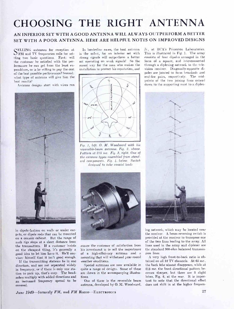
CHOOSING THE RIGHT ANTENNA AN INFERIOR SET WITH A GOOD ANTENNA WILL ALWAYS OUTPERFORM A BETTER
SET WITH A POOR ANTENNA. HERE ARE HELPFUL NOTES ON IMPROVED DESIGNS
SELLING antennas for reception at FM and TV frequencies calls for set-
tling two basic questions. First: will the customer be satisfied with the per- formance he can get from the least ex- penditure, or is he willing to pay the cost of the best possible performance? Second: what type of antenna will give him the best results?
Antenna designs start with wires run
in dipole -fashion on walls or under car- pets, or dipole rods that can be mounted on a console cabinet. But the range of such rigs stops at a short distance from the transmitters. If a customer insists on the cheapest thing, it's generally a good idea to let him have it. He'll con- vince himself that it isn't good enough.
If the transmitting stations lie in one direction, and are not separated widely in frequency, or if there is only one sta- tion to pick up, that's easy. The head- aches multiply with added directions and an increased frequency spread to be
covered.
June 1949 -- formerly FM, and FM
In borderline cases, the best antenna is the safest, for an inferior set with strong signals will outperform a better set operating on weak signals! So the surest way for the man who makes the installation to protect his reputation, and
o.
2151`
°ó
x ú W Z a
0
p Ö
6
D
\
4i
,
270 ` / 2pp 1/ '0./
i °Oe
Fig. 1, left. O. M. Woodward with his reversible -beam antenna. Fig. 2, above. Pattern at 215 mc. Fig. 3, right. One of the antenna types assembled from stand- ard components. Fig. 4, below. Switch
designed' to take coaxial leads
Jr., at RCA's Princeton Laboratories. This is illustrated in Fig. 1. The array consists of four dipoles arranged in the form of a square, and interconnected through a diplexing network to the tele- vision receiver. Diagonally- opposite di- poles are jointed to form broadside and end -fire pairs, respectively. The mid- points of the two joining lines extend clown to the supporting mast to a diplex-
assure the customer of satisfaction from his investment is to sell the importance of a high -efficiency antenna and a mounting that will withstand year -round weather conditions.
Special antennas are now available in quite a range of designs. Some of these are shown in the accompanying illustra- tions.
One of these is the reversible beam antenna, developed by O. M. Woodward,
RADIO -ELECTRONICS
ing network, which may be located near the receiver. A beam -reversing switch is provided at the receiver to transpose one of the two lines leading to the array. All lines used in the array and diplexer are the standard 300 -ohm balanced transmis- sion lines.
A very high front -to -back ratio is ob- tained on all 12 TV channels. At 65 mc., the back lobe almost disappears, while at 215 mc. the front directional pattern be- comes sharper, but there are 3 slight lobes, Fig. 2, at the rear. It is impor- tant to note that the directional effect does not shift in at the higher frequen-
27

cies, as is the case with some designs. Westinghouse Electric Corporation,
Pittsburgh, has developed a new idea in supplying component parts so designed that they can be assembled in any ar- rangement from a simple dipole to the high -gain array, as shown in Fig. 3. Thus, an antenna can be custom -made on the spot, to suit any local condition. Such parts as are used on a job can be replaced from stock when the truck returns to the service shop.
Arrays which can be made up from the elements used in the assembly illus- trated in Fig. 3 include:
1. Low-frequency or high- frequency di-
pole and reflector, 2. A combination of low- and high -
frequency dipoles and reflectors, 3. Stacked array with two low- or
high- frequency dipoles and reflectors, 4. Stacked array with four low- or
high- frequency dipoles and reflectors. Workshop Associates, Newton High-
lands, Mass., have specialized in antenna construction which feature high electrical efficiency and rugged design. A Work- shop antenna can be recognized readily by the circular, molded housing which supports the elements and protects the connections from smoke acids and rain. Also, they recommend the use of RG8 /U coaxial cable used with silver -plated, solderless connections.
The Workshop plan is to cut and orient a separate antenna for each chan- nel required if a 6- element array is used,
28
or for each group of three adjacent chan- nels if the antenna has 3 elements. Sepa- rate leads are brought to a coaxial switch, Fig. 4, to select the proper an- tenna for a given station.
When signals are not strong enough at a given location, the sure solution is to raise the height of the antenna. There
Fig. 5, left. This tower permits the mast to be slid up and down. Fig. 6, right, welded steel tower can be pushed up like a ladder. Fig. 7, above. Bevel gear is used to orient this antenna manually. Fig. 8, below. Two types of heavy
300 -ohm line
are some very handsome tower installa- tions around the country, but some look like accidents that are about to happen.
Wincharger has a convenient design, illustrated in Fig. 5. It is light, but strong enough to carry a man's weight, and needs no guy wires. The base mount- ing is suitable for a flat roof, or for fast- ening on both sides of a ridgepole. As Fig. 5 shows, the tower is intended to carry a 11 /4 -in. pipe. The pipe is put
in place before the antenna is fastened to it. Then, when the antenna and lead have been made secure, the pipe is run up and clamped at the top of the tower.
For greater height, there is the type shown in Fig. 6, made by the Easy -Up Tower Company, Racine, Wis. Three 10 -ft. welded sections weigh only 65 lbs:, and carry a 10 -ft. mast. When the hinged mounting feet are secured, it can be raised as easily as a ladder.
A simple method for orienting an an- tenna is offered by LaPointe Plascamold,
Unionville, Conn. This is shown in Fig. 7. The iron pipe carrying the antenna is supported on the side of the house, just below the eaves, but the weight is carried by a heavy casting at the bottom. This contains a bevel gear with a shaf t that goes through to a control handle inside, by which the mast can be rotated in any direction.
To satisfy those who feel that ordinary twin -line is not strong enough mechan- ically, or may deteriorate electrically, American Phenolic Corporation, Chicago, has brought out the heavier types shown in Fig. 8. One has solid, flat insulation of increased thickness. The other is a tube of plastic insulation with extra wall thickness to carry the two wires.
FM AND TELEVISION

CARBONYL IRON POWDERS A DESCRIPTION OF THE MANUFACTURING TECHNIQUES USED TO REDUCE IRON TO POWDER FORM FOR HIGH -FREQUENCY CORES - By GEORGE O. ALTMANN*
THE use of powdered iron cores at VHF and UHF frequencies is now
an established and well -known fact. The cores are used in transformers and in- ductance coils of every description and shape. They are used to boost Q values, to vary coil inductances, or to reduce the size of coils. Other functions are to con- fine stray fields or to increase transform- er coupling factors. The work they do may be very specific, as in wave traps and deflection yokes. Their uses are manifold. Up to about 1940 it was gen- erally believed that iron powder had no place at frequencies above 10 mc. except in the oxidized, low- permeability form. That this situation has changed so rad- ically is due, largely, to successful re- search on very small particle size iron powders with advantageous properties. These belong to the family of carbonyl iron powders.
Early Work on Iron Powders: The history of carbonyl iron powders1 goes back to the year 1890, when the British chemist Ludwig Mond discovered compounds resulting from a reaction be- tween a metal and carbon monoxide gas. The first was Ni (CO) 4 nickel tetra - carbonyl, a highly poisonous liquid, and then followed the crystalline Fez (CO) t iron ennea (or nona) carbonyl. When distillation at 100 deg. C was attempted in an atmosphere of carbon monoxide, the iron ennea -carbonyl instead enriched itself with CO to form iron penta -car- bonyl Fe (CO) 5, a yellowish liquid with a boiling point of 101.5° C. These re- actions presented considerable difficulties, but it was soon recognized that their intricacies could be turned to an advan- tage. The carbonyls that do form are not stable at elevated temperatures but decompose, under suitable conditions, in- to CO and the original metal. Here was a way to obtain metals in very pure form.
The British scientists and engineers in- vestigated this field systematically. Par- ticular attention was paid to high pres- sure and high temperature. After 1920 these developments were followed up in Germany. They led to the first large - scale industrial production of iron- penta- carbonyl for use as an anti -knock, and later to the manufacture of pure iron by means of continuous dissociation of this
*Physicist, Carbonyl Iron Powder Plant, Gen- eral Aniline & Film Corporation, 444 Madison Avenue, New York 22, N. Y.
1B. Pfeil, "Symp. Powder Met." Special Re- port No. 38, p. 47 -51, The Iron & Steel Inst., London, 1947.
compound. At first, up to about 1928, this purified iron was manufactured without attention to grain shape and structure, for the chemical and metallur- gical industries. Then, however, the in- fluence of heat and pressure on the fin- ished powder was examined2.
The discovery was made that carbonyl iron powder, when properly controlled, possessed excellent sintering properties. When it was made in the form of par- ticles of spherical shape with diameters of less than 20 microns, such particles had a very strong tendency to adhere to each other with surprising firmness after the usual heat treatments. The sinter - blocks formed in this way had greater strength and hardness than those made from other iron powders, and were often superior to articles made by way of fusion i.e. at very much higher tempera- tures.
In due course, this powder was ex- amined for use in electromagnetic cores where other powders, notably of electro- lytic origin, were used before. In view of its high mechanical hardness, it came as a surprise to discover a very low hy- steresis loss or narrow hysteresis loop. This is a very attractive feature for Pupin coils in the loading of telephone lines and the powder was immediately put to use for that purpose.3
Soon thereafter the powder was used for radio frequencies. New techniques of core making had to be developed. Among them, Polydoroff's4 was prob- ably the most successful. A main fea- ture is the efficient coating of the indi- vidual particles with insulating matter before compounding. A plastic binder is used which hardens at relatively low temperatures. In this way, insulation between particles remains undestroyed. Eddy currents develop only inside each particle and not over groups of them. Since eddy currents are proportional to the area over which they are produced, and are also proportional to the square of the frequency, these innovations were highly important.
An earlier creation was the material Ferrocart by H. Vogt.5 It was essen- tially a combination of iron powder and paper. Other companies in several coun- tries followed these developments and
2Schlecht, W. Schubardt & F. Duftschmid, Zs. Elektrochemie 37, 485 -492 (1931).
SW. Deutschmann, Tele. Fernsp. Tech 20 (1931) Heft 6.
4W. J. Polydoroff, Proc. IRE, 21, May 1933. 5H. Vogt, Wireless World 31, 272 -273 (1932). °A. Crossley, Electronics, Nov. 1933. 7F. Colebrook, Dept. Sci. & Indust. Res. -Spec.
June 1949 -formerly FM, and FM RADIO -ELECTRONICS
began production of molded powdered iron cores. According to Pfeil1 "there is little doubt that the main reason for the success of the development was the use of carbonyl iron powder."
Among the important publications of the 1930's in this field was A. Crossley's° description of an iron -core IF transform- er. Also F. Colebrook? wrote the first comprehensive treatise on magnetic ma- terials at radio frequencies. A theoret- ical discussion of the power losses of carbonyl iron powders then in use was published by Kornetzki and Weiss in 1936.
By 1941, a carbonyl iron plant° had been built in the United States by the General Aniline & Film Corporation. Electronic equipment for warfare de- manded large quantities of powdered iron cores, the majority of which was made with carbonyl iron powders pro- duced in this plant.
New grades of carbonyl iron powders were developed, particularly suitable for high frequencies. The production of these grades went hand in hand with improvements in core fabrication and coil design, such as were described, for example, by Martowicz10 in 1945.
The key to an understanding of the interesting properties of these powders is furnished by a consideration of the way they are prepared.
Preparation of Iron Powders: Carbon monoxide is passed at elevated temperatures over crude metallic iron. Fe (CO) 5 is formed as a vapor and carried away with the gas current from which it is separated by cooling, and is collected.11
The decomposition of the iron penta- carbonyl is accomplished in a large cylin- drical vessel heated to a temperature above 200° C. The starting materials, iron and carbon monoxide, are re- formed. The liberated iron atoms grow to spher- ical particles. These are removed from the gas stream and processed into the final carbonyl iron powders.
The growth of a particle is a some- what complicated matter. Ordinarily, iron arranges itself in a cubic crystal lat- tice which should lead to angular par- ticles instead of spheres, as is the case of nickel, for example. The actual mech-
Rep. No. 14 London 1934. 8M. Kornetzki & A. Weis, Wissenschaft!, Veroff.
Siemens Wke. 15 95 -111 (1936). °G. J. Comstock, Steel 108, 88 (1941) . 15C. T. Martowicz, Electronic Ind., June 1945. 111.1. S. Patent 1,783,744.
29

anism, according to Pfeil' and others, appears to be as follows:
The particle proceeds from a tiny cubic nucleus of iron. The surrounding gas film becomes impoverished in iron penta- carbonyl and enriched in CO. At the same time, heat is used up because the decomposition reaction is endother- mic. Consequently, further decomposi- tion and growth are temporarily slowed. At this point, another decomposition re- action is favored with the iron as a ca- talyst. This is the dissociation of carbon monoxide according to the equation QCO = C +CO2, an exothermic reaction. Its effect is three -fold. 1) The concentra- tion of CO in the neighborhood of the particle decreases, making room for new supplies of iron penta- carbonyl, 2) the particle regains heat it had lost, which it can use for further growth, and 3) carbon has been chemically absorbed which reduces the catalytic action of the iron for further CO dissociation. The particle is ready to receive some more iron and repeat the cycle. The end re- sults are clearly not homogeneous par- ticles, but particles whose carbon content radially, alternatingly increases and de- creases. Simultaneously, the particles also reduce some CO2 they have helped form to CO, and absorb most of the oxygen.
Crystal growth is seemingly hampered by the presence of these other elements, although each amounts to less than 1% by weight. The crystals do not exceed about one -hundredth of the particle diameter, and thus contain perhaps only a few hundred atoms in each direction.2 This smallness, together with formation in free space, is responsible for random growth of the particles and, hence, their spherical shape. Under a high -powered microscope, with a magnification of 500 times or more, the spherical shells can be observed as circular concentric rings alternately darker and lighter hue, pro- vided the particle has been mounted, etched with nitric acid, and polished. Usually between 5 and 10 of these rings can be seen, but the indication is that there are actually many more. The crystal size and type are deduced from X -ray diffraction patterns.
Mechanical Characteristics: It is easily seen that in a particle of such a structure, plastic flow will be impos- sible. The particles retain their shape even under the highest practically pos- sible pressures in hydraulic presses. Their hardness values are high. Pfeil' reports a Vickers diamond hardness of the order of 850. This is an advantage when efficient insulation is required, for the coating applied to a particle before mold- ing will not have to stretch over a de- formed particle after molding, as can
30
very easily be demonstrated in practice by comparing with non -carbonyl iron powders. Secondly, grinding and ma- chining is very easy. The core surfaces appear, and are in fact, very smooth be- cause the cutting tool can pry loose and remove the separate spheres much better than deformed and possibly interlocking grains. However, reports from core makers indicate that, in spite of hard- ness, wear on dies is not greater, prob- ably due to the roundness of the particle surfaces.
There is a drawback to the incompres- sibility. The air spaces remaining be- tween the particles even after molding prevent the available core volume from being filled with iron by more than about 65 %. This restricts permeabilities to values of about 15 or lower. Since there are usually large gaps in the magnetic circuits at the higher frequencies, low permeabilities are quite permissible, but higher permeabilities can be obtained through further treatment of the powder.
Soft Carbonyl Iron Powders: The essential feature of this softening treatment is, as would be expected, the removal of the carbon and oxygen, with concurrent crystal growth inside the par- ticles. This reduction is usually achieved by means of hydrogen and the applica- tion of heat. The powder emerges from the oven in the form of. soft chunks which break easily into single spheres and, occasionally, into clusters of two or more spheres. The spheres have lost their exact curvature. The electron microscope reveals them to have surfaces of small, flat facets which are, no doubt, the end faces of the various crystals in- side the particle.
These compressible particles permit much better use of a given volume. The air space within the core can be reduced from 35% to 5% and even less. Per - meabilities can be increased from 15 to 60 and more.12 However, as stated above, insulation is harder to maintain and, for that and other reasons, these powders do not find application above 5 mc. as a rule.
Size Distribution: The factor that most seriously limits the use of iron powder at higher frequen- cies is the power loss due to eddy cur- rents. The magnitude of the eddy cur- rents in every particle is proportional to the square of the diameter of the par - tice all other things being equal. The particle size distribution of any given powder is thus of paramount importance for the performance of that powder in a high- frequency core. A powder having half the average particle size of another
12G. O. Altmann and H. Beller, Electronic Ind., Nov. 1945.
one might possibly exhibit Q values 4 times as high. On the other hand, if the particles are too small, the required in- sulating matter may take up too much space, crowding out magnetic matter and lowering permeability. In some cases it is better to have particles of fairly uni- form size, while in other cases a great variety of sizes seems indicated as, for example, in the compressible powders whose cores should have most of their gaps filled.
The carbonyl process permits control óf particle size distribution by shifting, to some extent, the balance between the formation of new particles and the growth of those already existing.
The size distribution of the soft car- bonyl iron powders can be altered by changing the conditions of the reducing treatment, and also by breaking down the lumps into small particles more or less severely.
Summary: From the information presented, it can be seen that there are two different kinds of carbonyl iron powders: those obtained directly from the dècomposi- tion of the iron penta- carbonyl vapor, and the others which have been softened by an additional reduction treatment. Both are manufactured by the Antara Products Division of General Aniline and Film Corporation.
The "straight" carbonyl iron powders are composed of particles of about 0.5 to 15 microns in diameter. The particles are spherical, built up of concentric shells, and possess no porosity. They are made up of hundreds of small crys- tals, mechanically hard and practically incompressible. The hysteresis loss is very low. They are easy to insulate effi- ciently, so that eddy currents can be kept very low. Consequently they are very well- suited for high- frequency ap- plications.
The soft carbonyl iron powders are composed of particles which are spheres at first glance, but have many small, flat facets. A number of particles are clusters. The particles are homogeneous and are easy to deform. Hence, high densities can be attained which result in high permeabilities.
Some 700,000 shoppers in 150 Chicago supermarkets within a 40 -mile radius will hear FM music and announcement under a new arrangement between WMOR and Consumers Aid, Inc. Three -minute newscasts will be given on the hour, with time signals every quarter hour. Tran- scribed commercials will feature such entertainers as Bing Crosby and Jim Ameche. Survey shows 95% approval of store programs by shoppers.
FM AND TELEVISION
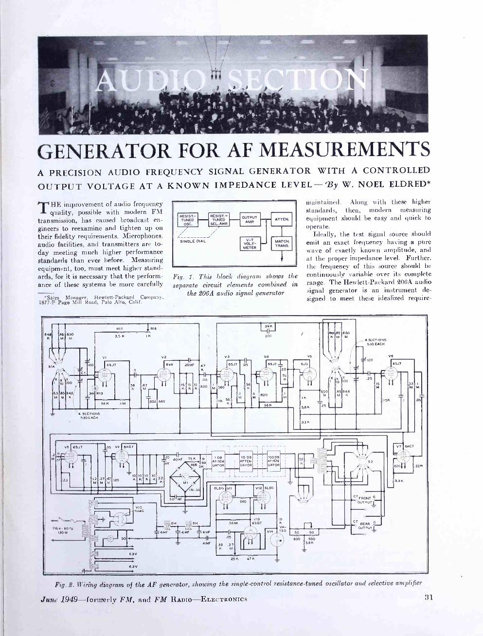
GENERATOR FOR AF MEASUREMENTS A PRECISION AUDIO FREQUENCY SIGNAL GENERATOR WITH A CONTROLLED
OUTPUT VOLTAGE AT A KNOWN IMPEDANCE LEVEL -3y W. NOEL ELDRED*
THE improvement of audio frequency quality, possible with modern FM
transmission, has caused broadcast en- gineers to reexamine and tighten up on their fidelity requirements. Microphones. audio facilities, and transmitters are to- day meeting much higher performance standards than ever before. Measuring equipment, too,, must meet higher stand- ards, for it is necessary that the perform- ance of these systems be more carefully
*Sales Manager, Hewlett -Packard Company, 1877 -F Page Mill Road, Palo Alto, Calif.
RESIST.- TUNED `T
L SINGLE DIAL
RESIST. - TUNED
SEL. AMP
OUTPUT AMP
V-T VOLT-
METER
ATTE N.
MATCH. TRANS.
i
Fig. 1. This block diagram shows the separate circuit elements combined in
the 206A audio signal generator
maintained. Along with these higher standards, then, modern measuring equipment should be easy and quick to operate.
Ideally, the test signal source should emit an exact frequency having a pure wave of exactly known amplitude, and at the proper impedance level. Further. the frequency of this source should be continuously variable over its complete range. The Hewlett- Packard 206A audio signal generator is an instrument de- signed to meet these idealized require-
846 e5 aso K M M
SIA IOO
Cl
VI
6SJ
10 110
8.5 .85 84.6 M M KI
3W
,T '4 SECTIONS
530 EACH
R13
55K
R17 7 R18
3,5 K I K
V2
6V6 20MF
56 47 15515 K K
.003 560 IM
.2 M
47
.05
p,1 t560
V 65t
56 K
56
L 39
200
V4
:820
6SJ7 I 20
v5
56 K
6J5
1K
5.8 K
9t 6j.85j8.50 K!M! M
r x x
650 Ì
.85I84.6 M M K
5
4 SECTIONS 530 EACH
100
II á 2s
V6
iis
3.3 K
15K
65.17
33
R
57
VB 6SJ7
.2 i1,2 ,27 , M M
,05 V9 64G7
,47 M
120
- 10 10110 K K
105
_120 40 MF 75 K
01-4
V10 U4G
6.3 V
6.3 V
MF
R 1 DB ¡
¡ 10 DB i 100 D8
R6B69 ATTELA I I ATTEN I I ATTEN.
2K UATOR H UATOR : ¡ UATOR - I I
© - I I 1
L__ _J L J --__ 4
IN-34 6L6G V12 6G
680
6L
- ol
I MF
.56 M
1I,--I,.,,-T-- 4MF 4MF 4MF r----il -
.05
- 4 N 33 .2 7, ' K M
V13 6507
25K 471(
10 K
VR- V14 150
56
K
50 50
600 600 5.K
CT FRONT O
OUTPUTi
O CT
REAR pG-
OUTPUTI
V' 16AC7
S3.3K
.05
.22 M
Fig. 2. Wiring diagram of the AF generator, showing the single- control resistance -tuned oscillator and selective amplifier
June 1949-formerly FM, and FM RADIO- ELECTRONICS 31

merits. The term signal generator is used here because this instrument has an exactly controlled output voltage which is transmitted at a known impedance level. A simple audio oscillator or test oscillator, on the other hand, delivers a signal at a known frequency but usually there is no mechanism for determining the exact amplitude or power level of the test signal.
In the generator to be described, it has been possible to keep the distortion below 0.1% over most of the frequency range. This has been accomplished with a circuit which combines a resistance - tuned oscillator with a resistance -tuned selective amplifier. The two units are tracked in such a way as to cause re- jection of the harmonics generated by the oscillator, but amplification of the fundamental voltage. Following the selective amplifier, there is an output amplifier whose level is monitored by a vacuum tube voltmeter. The output amplifier delivers its voltage to an at- tenuator system which is coupled to an impedance- matching transformer. This transformer is arranged to give a variety of output impedances, and is completely balanced to ground. The impedances available are: 50, 150 and 600 ohms. The arrangement of the signal generator is shown by the block diagram in Fig. 1.
The equipment necessary to make the complete gain and frequency response measurements is thus consolidated in, one unit. The only additional equip- ment required is an appropriate load for the instrument under test to work into, and some sort of an indicator which will show power in this load either on a volt- age or a current basis. This indicator need not have any absolute accuracy. The only requirement is that it be capa- ble of revealing a small change in level. It may be a simple AF vacuum -tube voltmeter, a copper oxide VU indicator, or the like. It is feasible, in making a test of this kind, to maintain the vacuum tube voltmeter in the signal generator at a standard value and, likewise, the in- dicator at the load at a standard value. The variation in gain as the various test frequencies are selected can be taken up by revising the adjustment of the atten- uator system in the audio signal genera- tor. Thus, the errors of the indicating meters are completely eliminated from the circuit, and the basic accuracy of measurement depends only on the at- tenuator system, which is better than 1/2
of 1 %.
Description of the Generator: The complete wiring diagram of the
Fig. 3, above. Interior of the AF signal generator. Fig. 4, center. Tuning conden- ser assembly. Fig. 5. Bottom of chassis
32
, ,,,,, .,,,,, ,!mo, Vti4,,, rz.u
t 1liY ._,. $(.1 " ,;t`i ,,Is
' i wnilmipi r ulirilìi, A N d e ,
I rriT".:::, . , tl ... u rii
1 1 . ..
FM AND TELEVISION

Above is a coaxial circuit crystal in its glass enclosure. At right the crystal is shown, 3% times actual sire, with connecting wires soldered in position. Weights on wires reflect energy back into crys- tal, so cut losses.
How would you solder a wire to a
crystal? This must be done for most
of those wafer -thin plates of quartz used in electrical circuits. They play
a big part in the myriad -channel tele-
phone system that utilizes , coaxial
cables.
This is how Bell Laboratories sci-
entists solved the problem: A spot of
paste containing silver is deposited on
the crystal and bonded to it by oven
heat. The crystal is then vapor -plated
with a thin layer of silver. Then a fine
wire is soldered to the spot by a con-
centrated blast of hot air. The result
is a rugged electrical connection to
the surface of the crystal which does
not interfere with its vibrations.
Sealed in glass tubes, the crystals
are precise and reliable performers in
the telephone system. Each is a crystal
gate to a voiceway, separating your
conversation from the hundreds of others which may be using a pair of coaxial conductors, at the same time.
This spot of paste, this tiny wire,
this puff of air are among the tremen-
dous trifles which concern Bell Tele- phone Laboratories in finding new
ways to improve your telephone service.
BELL TELEPHONE LABORATORIES PIONEERS IN THE RESEARCH OF FM RADIO AND TELEVISION, AND ACTIVE IN DEVELOPING IMPROVEMENTS IN BOTH FIELDS TODAY
June 1949-formerly FM, and FM RADIO-ELECTRON I LS 33

audio signal generator is shown in Fig. 2. with details of the design in Figs. 3, 4, and 5. The resistance -tuned oscillator section consists of the tubes V -1 and V -2. These tubes operate as a resistance - ccupled audio amplifier over which there is both positive and negative feedback. Positive feedback is directed through the resistance- capacity network in connection with the switch S1 A. These resistors, in conjunction with the variable capacitor Cl, are the frequency- determining net- work. This network will, at a single fre- quency, give a phase shift of exactly 180 °. Since the phase shift through the tubes V -1 and V -2 is exactly 360 °, then. the entire unit will oscillate at the fre- quency determined by the resistance - capacity network. The circuit elements are especially designed resistors of low temperature coefficient, having a maxi- mum long -time stability. This results in a fundamental accuracy of approximately 1c:4 over reasonable periods of time, and a long -time accuracy better than 2 %.
The negative feedback loop consists of resistors R -18, R -17 and R -13. The latter is a 3 -watt, 120 -volt incandescent lamp. It is a non -linear element which acts as an automatic amplitude limiter, and maintains the system at an optimum op-
the oscillator circuit so that it is respon- sive to the fundamental frequency and rejects the harmonic components. This amplifier consists of tubes V -3 through V -7. Tubes V -3 and V -4 are conven- tional voltage amplifiers, but V -5 is a cathode follower which has a Wein bridge, tuned to null at the fundamental frequency, in the output as part of its circuitry. This Wein bridge is another resistance- capacity network identical to that in the oscillator section previously
AF O5C 206A
AMP. UNDER TEST
LOAD
O I STOB: ANAL. 3306
Fig. 6. Measuring gain or AF distortion
described. The tuning condenser is ganged with the oscillator tuning con- denser, and the range switch is similarly ganged.
This ganged tuning arrangement is shown in Fig. 4. One four -gang con- denser controls the oscillator frequency, while the other controls the selective
Fig. 7. Setup for measuring frequency response, gain, or total harmonic distortion
erating point. The lamp provides flat frequency response over the entire range, and also assures that the tubes V -1 and V -2 operate on the linear portion of their characteristics. The negative feedback feature also reduces hum and distortion in the circuit.
TUNED AMPLIFIERS: The distortion gen- erated in the oscillator circuit is some- what in excess of the required 0.1%, and a selective amplifier is arranged to track
34
amplifier frequency. Located centrally between the two condensers is the ganged range -switch which selects the proper frequency -determining resistors.
Tuning the Wein bridge to a null elim- inates the fundamental frequency with- out appreciably affecting the harmonics present. These are amplified in V -6, a conventional voltage amplifier connected across the center of the bridge. This voltage is then fed to V -7, a cathode fol-
lower whose cathode circuit is returned to the cathode of V -3. This arrange- ment results in negative feedback for the harmonics but not for the fundamental frequency to which the bridge is bal- anced. The output for the circuit is taken ahead of the bridge circuit. Thus, this circuit Amplifies the fundamental fre- quency and rejects the harmonic fre- quency. A harmonic rejection of more than 10 db is obtainable by this process.
OUTPUT AMPLIFIER: Tubes V -8 and V -9 comprise the output amplifier. There is negative feedback over the whole so as to reduce distortion to a minimum, and the output of V -9 is connected as a triode so that the tube can work directly into the load of the attenuator system. Variable resistor R -57 serves an ampli- tude control.
VACUUM -TUBE VOLTMETER: The volt- meter uses a DC, 0 -1 milliammeter, M -1. It is connected into the circuit through a full -wave bridge rectifier, with four 1N34 germanium crystals as rectifier ele- ments. The meter is calibrated both in volts and in dbm (zero dbm =1 milli - watt in a 600 ohm load) . The series re- sistances R -68 and R -69 are provided for calibration.
ATTENUATOR: The attenuator gives a range of 111 db, variable in 0.1 -db steps. It consists of three separate decade at- tenuator elements, the first one variable in 0.1 -db steps and having a maximum attenuation of 1 db; the second section is variable in 1 -db steps and has a maxi- mum attenuation of 10 db; while a third section has 10 -db steps and a maximum attenuation of 100 db. The 1 -db atten- uator also serves to pad out the internal impedance to match the load impedance.
IMPEDANCE- MATCHING TRANSFORMER: The impedance- matching transformer for this generator represented a major design problem. It was necessary that this transformer have very low distor- tion and at the same time that its fre- quency response be flat over the range from 20 to 20,000 cycles, even at ex- tremely low levels. The resultant trans- former is very large physically compared to its power- handling capacity. It is wound on a special high -permeability core, with particular attention paid to the matter of output balance, shielding, and hum pickup. The secondary in the transformer is center tapped, and free from ground. The center tap is brought to the front panel so that the trans- former can be operated with a center tap, grounded on either end, or completely free of ground connection.
The overall design of the attenuator and impedance matching transformer is such that, beyond the vacuum tube voltmeter, the frequency response of the unit is accurate from 30 to 15,000 cycles within 0.2 db at all levels. Switch S -2
FM AND TELEVISION

Facts about Frequency Meters for
1ViOBILE COMIVIUNIC.ATIONS
FVERYONE is agreed that, under the new FCC alloca-
tions for the mobile services, and with the advent of adjacent -chan- nel operation, all fixed and mo- bile transmitters must be kept more closely to their assigned carrier frequencies than ever before.
But no matter how accurately a meter is calibrated at the fac- tory, its effective precision de- pends on the accuracy with which you can read the scale.
A BROWNING Frequency Meter can be set with greater precision because of the big dial and easy- reading vernier. They eliminate guesswork and assure the accuracy required by the FCC.
Then, there's the matter of drift. It's one thing to calibrate a meter at the factory, but you want to know how long the meter will retain that calibration. After all, meters used by communica- tions services can't be coddled like laboratory instruments.
When you specify a BROWN- ING Frequency Meter, you get a design that has gone through ten
Model S -4 and S -7 Frequency Meters
years of improvement and refine- ment. In addition, you get a basic advantage that is found in no other communications -type meter at any price. It is this:
Over a period of time, any make of meter will drift. The only way to determine if a meter has drifted beyond the limits specified by the FCC is to check it against the standard -frequency signals from the Bureau of Standards' station WWV.
B R O W N I N G LABORATORIES, INC. WINCHESTER, MASS.
IN CANADA, ADDRESS:
Measurement Engineering, Ltd., Arnprior, Ont.
EXPORT SALES
9 ROCKEFELLER PLAZA, Room 1422 NEW YORK 20, U. S. A.
But do you realize that BROWNING meters are the only communications - type instru- ments that can be checked against WWV in the field. To check a meter directly against WWV, the crystal must be a sub -multiple of a WWV fre- quency. Every BROWNING meter, at whatever point it is calibrated, uses a 100 -kc. crys- tal. With meters having crystals ground to a submultiple of the calibration frequency, you can't find out how much they have drifted.
Still, a BROWNING Fre- quency Meter is very reasonable in price. Model S -4 can be fur- nished with calibrations at 1 to 5 points in the band from 1.0 to 70 mc., accurate to .0025%, or model S -7 at 1 or 2 points be- tween 72 to 76 and /or 152 to 162 mc., accurate to .0025 %. The model S -5, with temperature - controlled crystal, can be cali- brated at 1, 2, or 3 points from 30 to 500 mc., accurate to .0025 %.
Use the coupon below to get detailed information promptly.
BROWNING LABORATORIES, 750 Main St., Winchester, Mas Please send me technical detai Browning precision products:
n S -4 Frequency Meter
S -5 Frequency Meter
nc. s. Is and prices on the following
S -7 Frequency Meter
WWV Frequency Calibrator
Name
Address
Company Connection
June 1949 -formerly FM, and FM RADIO -ELECTRONICS

selects the desired output impedance and also provides for a 600 -ohm single -ended operation, eliminating the output trans- former from the circuit for minimum dis- tortion and frequency response error.
The calibration of the output meter and attenuator are applicable only when the instrument is operating into a matched,resistive load, and the volts cali- bration applies only when operating into a matched, resistive 600 -ohm load. The internal impedance of the generator is always equal to the load impedance into which the instrument is designed to operate, and thus it is possible to cal- culate directly the voltage impressed across loads having impedances other than the standard values of 50, 150 or 600 ohms.
Very careful shielding of the output transformer results in a hum level that is at least 70 db below the output level, or more than 100 db below zero level, whichever hum voltage is the larger.
POWER SUPPLY: The complete unit is powdered by a full -wave rectifier, con- sisting of a single 5U4G followed by a conventional filter. A voltage regula- tion system keeps the plate voltage con- stant on all the tubes and thus contrib-
within the limits specified after a brief warmup although a 30- minute interval is necessary if greatest accuracy is re- quired.
The frequency is selected by a com- bination of the range switch and the fre- quency control dial previously described. In order to keep hum at a level as far below the output voltage as possible, it is desirable to set the amplitude control such that the reading on the vacuum
AF OSC. 209A
AMP UNDER
TEST LOAD
METER NO ACCURACY
REQUIRED
Fig. 8. Measurement of frequency response
tube voltmeter is +15 dbm. This is the maximum output level obtainable. Lower levels are obtained by inserting the nec- essary amount of attenuation. The level across the load is calculated as the alge- braic readings of the vacuum tube volt- meter and the attenuator (considering the attenuator readings as minus) . For
Fig. 9. Using the 206A generator to check
utes to the frequency stability of the instrument, as well as reducing of the hum in the power supply voltage.
Application Data: The instrument is ready for operation
as soon as it is connected to 115 volts, 50 -60 cycles, and .after it has been al- lowed to warm up for a few minutes. The frequency calibration will be well
36
modulation percentage on an FM monitor
example, if a level of -20 dbm is re- quired, the output attenuators should be set at 35 db ( +15 -35 = -20) .
For calculation of the voltage 'applied to 600 -ohm loads, it is convenient to re- call that attenuation of 20 db reduces the output voltageto 1 /10. An attenuation of 40 db reduces it to 1 /100, 60 db re- duces it to 1 /1000, and so on. Further, an attenuation of 10 db reduces the out-
put voltage approximately 3 to 1, or an attenuation of 1 db reduces the voltage approximately 12 %. Keeping these fig- ures in mind, it is possible to calculate quickly the amount of attenuation re- quired to obtain the exact output volt- age desired without reference to charts or tables. For example, to select an out- put voltage of .005 volts the vacuum tube voltmeter should be set to 5.0 volts and the 10 db step attenuator should be set to 60 db.
Voltages at the 150 -ohm impedance level and 50 -ohm impedance level can be calculated by applying the proper mul- tiplying factor. The factor for 150 ohms is 0.5 of the indicated voltage, and for 50 ohms it is 0.29.
It must be remembered that the out- put attenuator works properly and the calculated voltages are correct only when the instrument is matched to the proper resistive load. Before making any se- ries of measurements, it is well to inves- tigate the type of load into which the signal generator is operating. If the load is a resistive network, it may be possible to determine its value by the use of a simple ohmmeter. Usually; how- ever, this is not the case, and it is nec- essary that the load be measured under dynamic conditions, that is, when operat- ing with an AC voltage. The value of the load may be roughly checked by measuring the output voltage across the signal generator with a high impedance vacuum tube voltmeter under the condi- tion of no load. Then, connect the load. This should cause the voltage to drop to exactly one -half of its original value. Nor- mally, a test of this kind is made at a standard frequency of 1000 cycles.
In the event that it is not possible to supply a matched load, then it is neces- sary to calculate the actual voltage im- pressed across the input of the equipment. This is calculated by the formula:
Eo x RL EL =
RL + 600 Where:
EL = voltage across load Eo = measured open circuit load or
VTVM reading x 2 (at 600 ohm level)
RL " load resistance 600 = the selected generator output
impedance This formula can be used for other set- tings of switch S2 by substituting the proper impedance for 600, i.e., either 150 or 50 ohms.
To estimate the load impedance, this formula can be rewritten as:
600 x EL RL
Eo - EL These formulas apply only when the load is resistive. There will be some error if a reactive component is present.
FM AND TELEVISION

.,:. d Aó
Type 1301 -A Low- Distortion Oscillator
Here's Your "PROOF -OF- PERFORMANCE"
AS ANNOUNCED by the Federal Communications Com- mission,* effective August 1, 1949 all a -m and f -m broadcast stations will be required to make proof -of- performance checks of over -all noise and distortion of the complete station at least once a year.
Many stations already make these measurements at fre- quent intervals as routine operating maintenance to insure the continuous high -quality service the modern transmitter system is capable of supplying.
General Radio instruments for these measurements have been available for some time, and are in regular use by the leading stations where this equipment has given accurate, convenient -to -use and trouble -free service.
The G -R Type 1932 -A Distortion and Noise Meter meets all of the F.C.C.'s requirements for measurements of this type for both a -m and f -m services; the Type 1301 -A Low- Distor- tion Oscillator is the ideal companion unit for use with the Type 1932 -A. Both of these instruments are relay -rack mounted and can be supplied in panel finishes to match most existing installations.
TYPE 1932 -A DISTORTION & NOISE METER
For measurements of sine -wave voltages, distortion and noise throughout the audio range. Over -all pass -band of the volt- meter circuit extends to 45,000 cycles, thus including all
*F.C.C. Rules and Regulations, Sections 3.254 and 3.46, as
amended
noise and distortion products contained in this range; particularly the 3rd harmonic of a 15,000 -cycle test is in- cluded.
This instrument is continuously adjustable and can be set to any frequency quickly since it has only one main tuning control plus a small trimmer. With it measurements can be made on a -f distortion in radio transmitters, line amplifiers, speech amplifiers, speech input equipment to lines; noise and hum levels of a -f amplifiers, wire lines to the transmitter, remote pick -up lines and other station equipment.
Full -scale deflections on the large meter read distortions of 0.3, 1, 3, 10 or 30 per cent; range for carrier noise measure- ments extends to 80 db below 100% modulation, or 80 db below an a -f signal of zero dbm level. The a -f range is 50 to 15,000 cycles, fundamental, for distortion measurements and 30 to 45,000 cycles for noise and hum. Type 1932 -A Distortion and Noise Meter: $575.00
TYPE 1301 -A LOW -DISTORTION OSCILLATOR
Especially designed for rapid measurements, this highly - stable oscillator has exceptionally low distortion. By means of push buttons, 27 fixed frequencies between 20 and 15,000 cycles may be selected in logarithmic steps. Any frequency between steps can be obtained by plugging in external re- sistors. The distortion over the entire range will not exceed the following percentages: with 5,000 -ohm output, 0.1 % from 40 to 7,500 cycles; 0.15 % at other frequencies. With 600 -ohm output 0.1 % from 40 to 7,500 cycles; 0.25 % from 20 to 40 cycles and 0.15 % above 7,500 cycles.
The oscillator is calibrated to within ±(11/2% + 0.1 cycle); the calibration is not affected by changes in load or plate supply voltage; drift is less than 0.02 % per hour after a few minutes operation. The operation of the oscillator is unaf- fected by ordinary climatic changes. Type 1301 -A Low Distortion Oscillator: $395.00
GENERAL RADIO COMPANY Cambridge 39, Massachusetts
90 West St., New York 6 920 S. Michigan Ave., Chicago 5 1000 N. Seward St., Los Angeles 38
.//l/,(' 1949 -formerly FBI, and FM RADIO- ELECTRONICS 37

Gain and Distortion: Fig. 6 shows a typical setup to meas-
ure gain or audio distortion, with a photograph of the equipment in Fig. 7. Here, the model 206A is used in conjunc- tion with a Hewlett- Packard 330B dis- tortion analyzer. The only additional equipment required is an appropriate load on the amplifier or equipment under test. This usually is a simple resistance. To measure gain, only the vacuum tube voltmeter section of the 330B is em- ployed. Then gain is simply calculated as the ratio of the output to input volt- ages, taking into account the impedance ratios. If the impedances are both the same, the gain is the simple ratio of output to input voltages. Where impe- dance levels differ, a correction should be made. In many cases, gain of the equipment is stated without reference to the impedance level, although this is not strictly a correct procedure.
Frequency Response: A typical test setup for measuring fre- quency response is shown in Fig. 8. The frequency is controlled by means of the main tuning dial and an auxiliary range switch. The total range covered is 20 to 20,000 cycles. The tuning dial is cali- brated in cycles for the lowest frequency range, 20 to 200 cycles. The second range provides a 10 times multiplier and the frequency covered is 200 to 2,000 cycles, while the third range provides a multiplier of 100 and the frequency cov- ered is 2,000 to 20,000 cycles. Thus, the instrument covers the complete audio spectrum continuously. It is possible to study in complete detail the frequency response, audio distortion, and transient response of a particular audio system. Hence, peaks or transient responses can be detected which might possibly go un- noticed if the analysis were limited to discreet steps of frequency.
The use of a continuously -variable generator is also valuable in the measure- ment of unknown frequencies. For exam- ple, a spurious frequency of oscillation occurring in an audio system can be com- pared with the audio signal generator frequency by means of an oscilloscope. This type of a measurement frequently gives a clue to the source of the spurious oscillation.
Percentage of FM Modulation: Measurements of the percentage modu- lation of an FM transmitter to calibrate the reading of the station modulation monitor, may be made employing the 206A. Fig. 9 shows the setup. The FM carrier in unmodulated condition is de- tected by means of a communications receiver, employing a beat frequency os- cillator to give a beat note of a suitable pitch. This may be done at the carrier
38
frequency, or frequently it is more con- venient to detect the carrier at the inter- mediate frequency employed in the dis- criminator circuit of the modulation monitor.
As sine -wave modulation is gradually applied to the transmitter. The ampli- tude of the transmitter carrier, and hence the receiver beat note output, will go through successive amplitude nulls. The combinations of nulls can be computed using the folloing relation:
modulating frequency Mod. index =
frequency swing These values of modulation indices are
given in the table below: NULL No.
1
2
3
4
5
6
7
8 9
10 Thus,
MOD. INDEX
2.405 5.520 8.654
11.792 14.931 18.071 21.212 24.353 27.494 30.635
by selecting the proper fre- quency of the signal generator, a calibra.. tion point can be selected for any de- sired percentage of modulation, thereby checking exactly the calibration of the modulation monitor.
TV IN SMALL CITIES (Continued from page 26)
first video input in the switching system. This is to remove disturbances in the signal obtained from the network line, and to re- establish the proper sync -to- picture ratio before feeding the incoming remote into the transmitter. This am- plifier utilizes clamp circuits to estab- lish fixed levels for peak -of -sync and for black level. Other viedo inputs are equipped with mixing amplifiers to con- trol gain of local video signals and to mix sync with these signals. Two inputs not used in this switching unit allow the subsequent addition of local studio or re- mote field pickup equipment, or both.
Facilities are provided in the turret for switching and monitoring any of the five audio channels. Gain controls are provided for each channel, with direct level- reading on the VU meter in the transmitter control section. Provision is made to permit the microphone chan- nel to be mixed with any other of the four input channels.
By pressing the microphone button and the network button, for example, the microphone can be used to override the network for a station break. The audition switching bank of the turret is arranged in a similar manner. Audio signals contemplated for this system in- clude the microphone in announce booth,
network sound, film sound, turntable, and one open input.
The system is quite flexible, due to accessibility of the audio and video jack panels. .If an expansion of facilities is contemplated at some future time, pro- visions are available for switching two additional video inputs by adding stabi- lizing amplifiers and their power supplies. Fig. 3 shows the functional operation of both video and audio signals in the switching unit. Open provision for addi- tional video can be seen in this diagram.
Five racks are used to provide entire video and audio power, equalization, stabilization and distribution, as shown ir. Fig. 7. The equipment contained in this bank of racks is so arranged as to leave space for the addition of one in- coming video signal without additional rack requirements.
Minimum Layouts: The system layout for a secondary type television station which has been de- scribed represents a maximum of operat- ing and programming flexibility at low cost.
However, this is by no means the mini- mum in equipment requirements for tel- vision operation. Many broadcasters have visualized virtual slave- station operations which would originate no local video signals, but only serve as repeaters for existing stations. Such a network - only operation would require merely the transmitter and antenna portions of the system described here. Operation of a film -only video outlet would also require less terminal equipment and program switching facilities.
It is considered, however, that in gen- eral the additional variety provided in a film- and -network operation will find wider acceptance than either an exclusive film or network type of operation. The Basic Buy, as outlined here, is a mini- mum operation as regards equipment and initial investment in a station for both film and network programming.
Future Expansion: The switching and distribution portion of the control system has open provisions for two additional video inputs to accom- modate a very large degree of growth on the part of the individual station.
Similarly, the output of a standard two -camera image -orthicon chain can be fed into the existing system, either from a local studio or from a remote location, such as a ball park, civic auditorium, etc. Remote pickups are generally carried to the transmitter via microwave relay equipment but, in many cases, the use of an equalized -pair telephone line will further serve to follow the keynote of economy upon which this entire design has been based.
FM AND TELEVISION

Advertisers' Index
Adair, George P 10
Alden Products Company 9
Alford, Andrew 10
Altec Lansing Corp 39
Amy, Aceves & King, Co. Inc 9
Bell Telephone Labs 35
Boonton Radio Corp 39
Camera Equipment Co 7
Collins Audio Products Communications Research
Corp
9
10
Daven Co., The 3
Davis, George C 10
Eitel- McCullough, Inc 40
Electrical Reactance Corp Inside Back Cover
FM-TV 6 .11
General Radio Co 37
Graybar Electric Co 10
Harvey Radio Labs., Inc 11
Hewlett- Packard Co Inside Front Cover
Hughey & Phillips Co 9
Jansky & Bailey 10
Kay Electric Co 9
Kear and Kennedy 10
Link Radio Corp 8
May Russell P 11
McCachren, Winfield Scott . 11
McIntosh, Frank H 10
McNary and Wrathall 10
Motorola, Inc f0, 21
National Co 4
No. American Philips Co. Inc. Back Cover
Pollack, Dale 10
Radio Apparatus Corp 3
Radio Corp. of America 1
Radio Music Corp 9
Rangertone, Inc 9
Ray, Garo W 10
Smeby, Lynne C 11
Sylvania Electric Pdts., Ins 5
Topflight Tape Co
Weldon & Carr 10
Western Electric Co 12
Williams, Nathan 11
Wilmotte, Raymond M 11
Workshop Associates, Inc 9
Zenith Radio Corp
June 1949 -formerly FM, and FM
ALTEC LANSING
has the correct answers to your sound problems
eis Oler f
Regardless of your problem of high quality sound reproduction and distri- bution, you will find the solution with one or a combination of the highest quality units in the Altec Lansing line. From a small, efficient, 8 -inch speaker to a huge industry approved theatre loudspeaker system, AltecLansing man- ufactures over 25 different types and sizes of speakers and speaker systems. Each unit has been especially designed to adequately solve a specific sound problem. Thousands of Altec Lansing speakers are now in use in the motion picture, public address and radio in-
dustries. If your problems are sound, consult Altec Lansing. You will find the right answer to your sound problems.
Write for descriptive brochure
1 LTEC LANSING CORPORATION
1161 N. Vine St., Hollywood 38. Cal. 161 Sixth Ave., New York 13, N. Y
BOONTO BOONTONNJ U-S A
R.ADIO--ELECTRONICS
160 -A Q METER The 160-A 0-Meter is unexcelled for laboratory and development applications, having received world wide recognition as the outstanding instrument for measuring Q, inductance, and capacitance at radio frequencies.
Frequency Range: 50 kc. to 75 mc. (8 ranges) 0 Measurement Range:20 to 250 (20 to 625 with multiplier) Range of Main Cl Capacitor: 30 -450 mmf. Range of Vernier Q Capacitor: +3 mmf., zero, -3 mmf.
ADIO For further specifications and descriptive
details, write for Catalog F

Follow the Lroder3 to
tetrode h ABOUT THE 4X150A . . ' ' anode type late
compact external anode power at low P
This extremely high-output an r -f amplifier or
capable of relatively intended for use as wide -band
voltage. It is intended is used
extensively as a high - 4ideoAand in single or multi -tube
oscillator. The video equipment. Good operational
amplifier for ultra-high-frequency t.
Good
high-
power ultra -hig maintained up to
characteristics CHARACTERISTICS ELECTRICAL
CH 6 0 volts
Coated Uni potential amperes Cathode Voltage - - - 2.6 amp 5.0
Heater Current Factor (Average) Grid Amplification (Average) 0.02 uuf.
Input
Screen-Grid Capacitances (
without shielding) I62 uuf. Direct IntGeld Platte (without - _ 6.1 uuf.
Output - -
500 Output ma., e 12,000 umhos. - -
Transconductanc 2501x.)
250 m L -
TELEPHONY E` TELEGRAPHY
OR FM
CLASS -C TELEG to 500 Mc.) Volts
Ratings; (Frequencies up
- Mc. Max.
Maximum 250 Max. Volts
D -C Slate Voltage
- _250 Max. Volts s
D -C Screen Voltage 250 Max. Ma.
D -C Grid Voltage - 150 Max. Watts
D -C Plats Current 15 Max. Waits Dissipation
Max. Watts Plaid Dissipation Screen Dissipation - request. Grid
Complete data available on req
40
Skill in the form of old fashioned individual dex- terity, teamed with modern manufacturing tech- niques, plays a very important part in the manu- facture of better vacuum tubes . . . Eimac tubes.
Craftsmanship of Eimac employees is the result of years of training at one specific art . . . vacuum tube assembly . . . and the degree of proficiency they have attained is manifest in the quality of the product they produce.
Illustrated is the screen -grid assembly operation of the Eimac 4X150A tetrode. Precise geometric alignment of these parts provides the excellent electron beam action in the 4X150A. This opera- tion is but one of over a hundred similar operations in the construction of this tube requiring the painstaking abilities of the Eimac craftsman.
EITEL-Mc(ULLOUGH, INC. 728 San Mateo Ave., San Bruno, California
Export Agents: Frazar & Hansen, 301 Clay St., San Francisco, California
FM AND .rl'r: l. l.\ I1()\

I/Nb \i%
COMPONENTS gpe 4
The Leaders in Radio-TV 8 4mmunisntions
FAIDA
RCA J/.kirìJi
a 0 Mp9
exos
nttP erdet' -and many others too numerous to list in this limited space. ,,,
ft14f CoMPO
BETTER R 4
WA PREcl510
Tested sfeP by
P from row
° lto Fin is he d
Product. Accuracy
guaranteo your
sPe
material
tolerance.
UNIFORMITY
Constancy of quality
is
over entire
m0
urin Ty
nterPret this factor terms
our customers'
Our iQ makes your product
better.
epr after
örovb eee M/ NgrVRlZgt/
ON The
smolt est BIG
the
your
Cos increase
your PrOÑ,5
make possible spore
factors which reduce
Hu-Q
Chassis of the popular EMERSON Model HI -CI components contribute their part eratiun.
611 Television set. to dependable
Look at the leaders in Radio, Television and Communications, and you'll find they look to HI -Q for quality components.
HI -Q engineers have worked closely with many of these companies in the develop- ment of electronic components demanded by the ever changing circuits of modern electronics.
These same engineers with their wide ex- perience are available to your company for confidential consultation. Write - wire -or phone. Three (3) plants exclusively devoted to the manufacture of ceramic capacitors, resistors and choke coils assure prompt de- livery of your orders.
Eeeceua1 eace«ce sié FRANKLINVILLE, N. Y.
Plants: FRANKLINVILLE, N. Y.- JESSUP, PA.- MYRTLE BEACH, S. C.
Sales Offices: NEW YORK, PHILADELPHIA, DETROIT, CHICAGO, LOS ANGELES

Norelco R O TE L G R AIV
LIFE-SIZE
Chosen by these famous makers of quality projection TV receivers
ANSLEY EMERSON FADA FISHER PILOT SCOTT STEWART WARNER INTERNATIONAL
TELEVISION BRUNSWICK
and others soon to be announced
PROTELGRAM is the result of nearly fifteen years of research by the world's greatest electronics laboratories. This scientifi-
cally designed, optically correct projection system
makes possible, for the first time, a life -size distor- tion -free picture of nearly 200 square inches (20"
diagonal) ... a more life -like picture without glare or eyestrain. And from a tiny long -life,
low -cost picture tube!
PROTELGRAM- equipped sets provide your finest profit opportunity for 1949 because they offer your customers what they want -a bigger, clearer picture that is easier on the eyes. Get the facts today from the above manufacturers on the out- standing sales and profit advantages of their PROTELGRAM- equipped receivers. Or write to Dept. PC-6, North American Philips Company, Inc., 100 East 42nd St., New York 17, N. Y.


![2014.07.03, VDI Freising [Kompatibilitätsmodus]DOMEX 355 MC DOMEX 420 MC DOMEX 460 MC DOMEX 500 MC DOMEX 550 MC DOMEX 600 MC DOMEX 650 MC DOMEX 700 MC Corus Ympress S355MC Ympress](https://static.fdocuments.net/doc/165x107/5e5aafa79c24815d6a60d8f2/20140703-vdi-freising-kompatibilittsmodus-domex-355-mc-domex-420-mc-domex.jpg)