Tutorials: Lighting - Autodesk · Lighting Tutorials The tutorials in this section show you how to...
146
Tutorials: Lighting Design 2010
Transcript of Tutorials: Lighting - Autodesk · Lighting Tutorials The tutorials in this section show you how to...

Tutorials:Lighting
Design 2010

Autodesk® 3ds® Max Design 2010 Software© 2009 Autodesk, Inc. All rights reserved. Except as otherwise permitted by Autodesk, Inc., this publication, or parts thereof, may not bereproduced in any form, by any method, for any purpose.Certain materials included in this publication are reprinted with the permission of the copyright holder.The following are registered trademarks or trademarks of Autodesk, Inc., in the USA and other countries: 3DEC (design/logo), 3December,3December.com, 3ds Max, ADI, Alias, Alias (swirl design/logo), AliasStudio, Alias|Wavefront (design/logo), ATC, AUGI, AutoCAD, AutoCADLearning Assistance, AutoCAD LT, AutoCAD Simulator, AutoCAD SQL Extension, AutoCAD SQL Interface, Autodesk, Autodesk Envision, AutodeskInsight, Autodesk Intent, Autodesk Inventor, Autodesk Map, Autodesk MapGuide, Autodesk Streamline, AutoLISP, AutoSnap, AutoSketch,AutoTrack, Backdraft, Built with ObjectARX (logo), Burn, Buzzsaw, CAiCE, Can You Imagine, Character Studio, Cinestream, Civil 3D, Cleaner,Cleaner Central, ClearScale, Colour Warper, Combustion, Communication Specification, Constructware, Content Explorer, Create>what's>Next>(design/logo), Dancing Baby (image), DesignCenter, Design Doctor, Designer's Toolkit, DesignKids, DesignProf, DesignServer, DesignStudio,Design|Studio (design/logo), Design Web Format, Discreet, DWF, DWG, DWG (logo), DWG Extreme, DWG TrueConvert, DWG TrueView, DXF,Ecotect, Exposure, Extending the Design Team, Face Robot, FBX, Filmbox, Fire, Flame, Flint, FMDesktop, Freewheel, Frost, GDX Driver, Gmax,Green Building Studio, Heads-up Design, Heidi, HumanIK, IDEA Server, i-drop, ImageModeler, iMOUT, Incinerator, Inferno, Inventor, InventorLT, Kaydara, Kaydara (design/logo), Kynapse, Kynogon, LandXplorer, LocationLogic, Lustre, Matchmover, Maya, Mechanical Desktop, Moonbox,MotionBuilder, Movimento, Mudbox, NavisWorks, ObjectARX, ObjectDBX, Open Reality, Opticore, Opticore Opus, PolarSnap, PortfolioWall,Powered with Autodesk Technology, Productstream, ProjectPoint, ProMaterials, RasterDWG, Reactor, RealDWG, Real-time Roto, REALVIZ,Recognize, Render Queue, Retimer,Reveal, Revit, Showcase, ShowMotion, SketchBook, Smoke, Softimage, Softimage|XSI (design/logo),SteeringWheels, Stitcher, Stone, StudioTools, Topobase, Toxik, TrustedDWG, ViewCube, Visual, Visual Construction, Visual Drainage, VisualLandscape, Visual Survey, Visual Toolbox, Visual LISP, Voice Reality, Volo, Vtour, Wire, Wiretap, WiretapCentral, XSI, and XSI (design/logo).
TrademarksThe following are registered trademarks or trademarks of Autodesk Canada Co. in the USA and/or Canada and other countries: Backburner,Multi-Master Editing, River, and Sparks.The following are registered trademarks or trademarks of Moldflow Corp. in the USA and/or other countries: Moldflow MPA, MPA (design/logo),Moldflow Plastics Advisers, MPI, MPI (design/logo), Moldflow Plastics Insight, MPX, MPX (design/logo), Moldflow Plastics Xpert.clothfx™ is a trademark of Size8 Software, Inc. Havok.com™ is a trademark or registered trademark of Havok.com Inc. or its licensors. Intel is aregistered trademark of Intel Corporation. mental ray is a registered trademark of mental images GmbH licensed for use by Autodesk, Inc. Allother brand names, product names or trademarks belong to their respective holders.
DisclaimerTHIS PUBLICATION AND THE INFORMATION CONTAINED HEREIN IS MADE AVAILABLE BY AUTODESK, INC. "AS IS." AUTODESK, INC. DISCLAIMSALL WARRANTIES, EITHER EXPRESS OR IMPLIED, INCLUDING BUT NOT LIMITED TO ANY IMPLIED WARRANTIES OF MERCHANTABILITY ORFITNESS FOR A PARTICULAR PURPOSE REGARDING THESE MATERIALS.
Lighting Tutorials
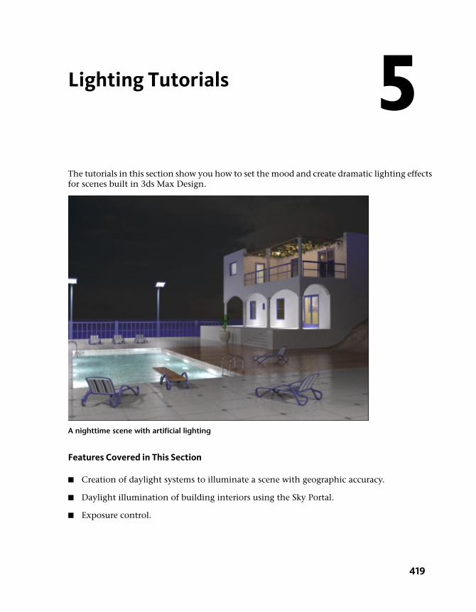
The tutorials in this section show you how to set the mood and create dramatic lighting effectsfor scenes built in 3ds Max Design.
A nighttime scene with artificial lighting
Features Covered in This Section
■ Creation of daylight systems to illuminate a scene with geographic accuracy.
■ Daylight illumination of building interiors using the Sky Portal.
■ Exposure control.
5
419
■ Shadow creation and definition.
■ Nighttime illumination using adjustable photometric lights.
■ Realistic scene illumination through use of Final Gather.
■ Photon control for effective distribution of light energy.
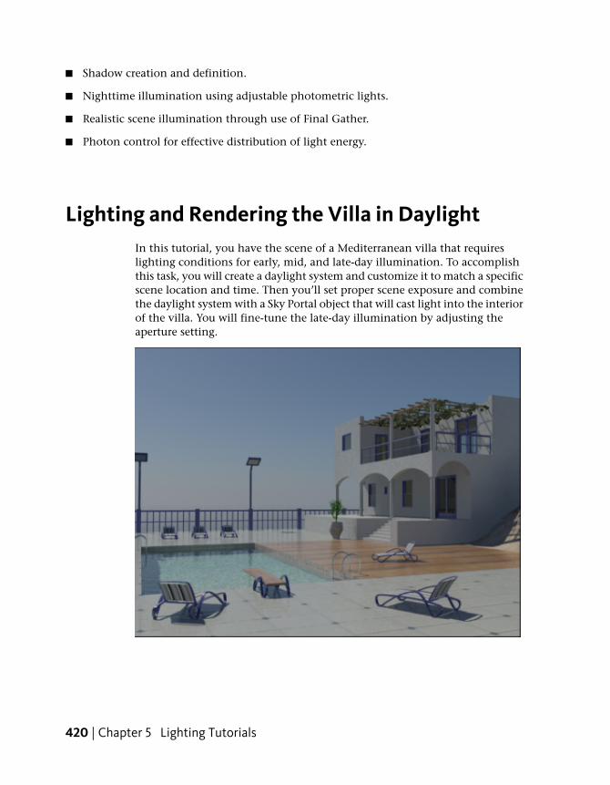
Lighting and Rendering the Villa in DaylightIn this tutorial, you have the scene of a Mediterranean villa that requireslighting conditions for early, mid, and late-day illumination. To accomplishthis task, you will create a daylight system and customize it to match a specificscene location and time. Then you’ll set proper scene exposure and combinethe daylight system with a Sky Portal object that will cast light into the interiorof the villa. You will fine-tune the late-day illumination by adjusting theaperture setting.
420 | Chapter 5 Lighting Tutorials

After completing this tutorial, you will see how easy it is to use mental raylighting options to create realistic daytime lighting conditions.
In this tutorial, you will learn how to:
■ Use daylight systems to illuminate a scene based on its geographic location,orientation, and time of day.
■ Use the Sky Portal object to gather skylight and apply it to the interior ofbuildings.
■ Adjust scene exposure to suit different times of the day.
Skill level: Intermediate
Time to complete: 1 hour
Adding Daylight Illumination
You will begin by looking at how the scene appears without any light objects.You’ll then add daylight to the scene.
Set up the lesson:
1 On the Quick Access toolbar, click the Open File button, navigateto the \scenes\lighting_and_rendering\med_villa folder, then open the scenefile med-villa-lighting-start.max.
2 From the main menu, choose Rendering > Environment. In theEnvironment And Effects dialog > Exposure Control rollout > drop-downlist, the exposure preset is set to the mr Photographic Exposure Control(“mr” is short for “mental ray”).
3 Choose <no exposure control> from the list.
Adding Daylight Illumination | 421

4 In the Rendered Frame window > Include In Render group, turn off FinalGather, and then click Render to render the scene again.
With the exposure settings removed, you can now see the scene in a verybasic way through default lighting.
The rendered result nonetheless appears flat and not very realistic. Youneed to add either man-made light sources or daylight to properlyilluminate the scene. In this tutorial, you will create daylight by generatingtwo mental ray photometric light sources:
■ mr Sun, which simulates direct light from the sun.
422 | Chapter 5 Lighting Tutorials

■ mr Sky, which simulates indirect light created by the scattering ofsunlight in the atmosphere.
These two light sources will be accompanied by the mr Physical Skyenvironment shader, which establishes the physical representation ofthe sun and sky.
Create the daylight system:
1 Close the Rendered Frame Window and the Environment And Effectsdialog.
2 On the Create panel, turn on Systems.
3 On the Object Type rollout, click Daylight to turn it on.
The Daylight System Creation dialog displays, recommending an optimumexposure value for mental ray.
4 Click Yes to accept the settings.
5 In the Top viewport, click anywhere over the scene and drag slightly inany direction to create a compass rose.
Adding Daylight Illumination | 423
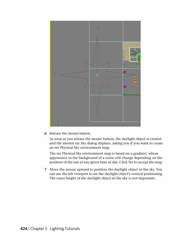
6 Release the mouse button.
As soon as you release the mouse button, the daylight object is createdand the mental ray Sky dialog displays, asking you if you want to createan mr Physical Sky environment map.
The mr Physical Sky environment map is based on a gradient, whoseappearance in the background of a scene will change depending on theposition of the sun at any given time of day. Click Yes to accept the map.
7 Move the mouse upward to position the daylight object in the sky. Youcan use the left viewport to see the daylight object’s vertical positioning.The exact height of the daylight object in the sky is not important.
424 | Chapter 5 Lighting Tutorials

8 Click once to set the Daylight object position, then right-click to endDaylight creation.
Set the time and location of the light source:
Now you will reposition the Daylight object, or “sun,” so its position in thesky corresponds to the geographic location of the scene.
1 With the Daylight object still selected, go to the Modify panel> Daylight Parameters rollout > Position group, click Setup.
Adding Daylight Illumination | 425

3ds Max Design opens the Motion panel.
2 On the Control Parameters rollout > Location group, click Get Location.
426 | Chapter 5 Lighting Tutorials

3 On the Geographic Location dialog, choose Europe from the Mapdrop-down list.
Adding Daylight Illumination | 427
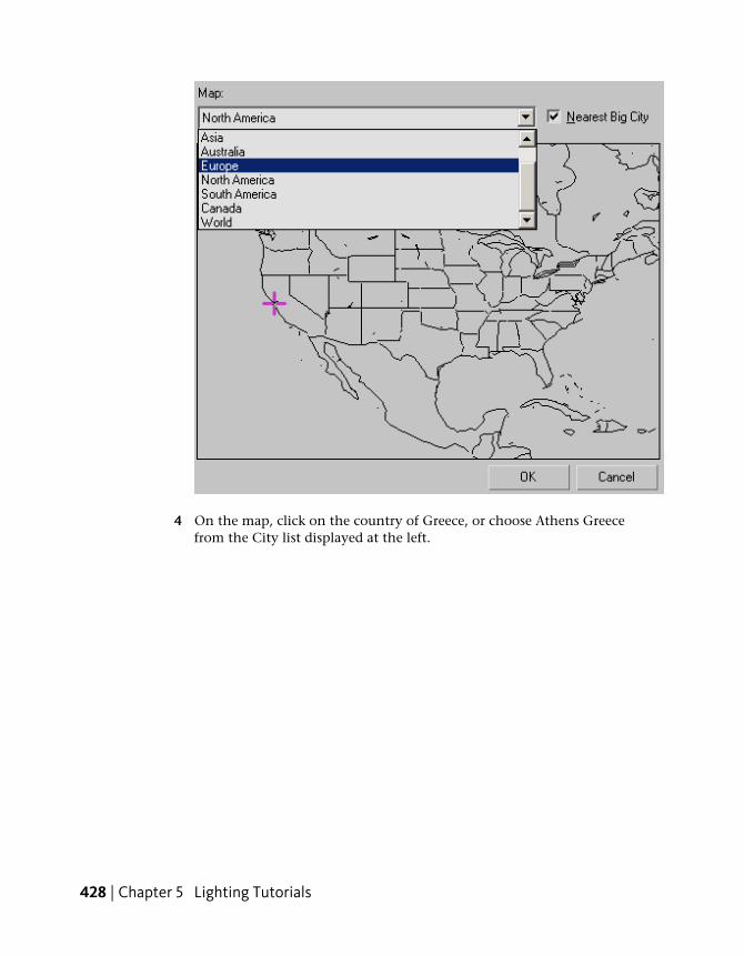
4 On the map, click on the country of Greece, or choose Athens Greecefrom the City list displayed at the left.
428 | Chapter 5 Lighting Tutorials
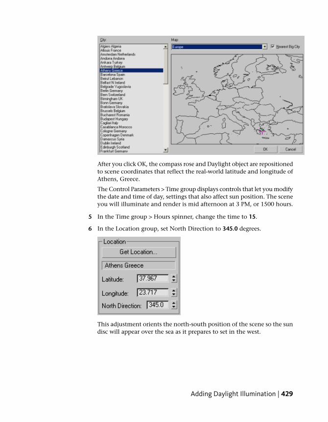
After you click OK, the compass rose and Daylight object are repositionedto scene coordinates that reflect the real-world latitude and longitude ofAthens, Greece.
The Control Parameters > Time group displays controls that let you modifythe date and time of day, settings that also affect sun position. The sceneyou will illuminate and render is mid afternoon at 3 PM, or 1500 hours.
5 In the Time group > Hours spinner, change the time to 15.
6 In the Location group, set North Direction to 345.0 degrees.
This adjustment orients the north-south position of the scene so the sundisc will appear over the sea as it prepares to set in the west.
Adding Daylight Illumination | 429
Set exposure:
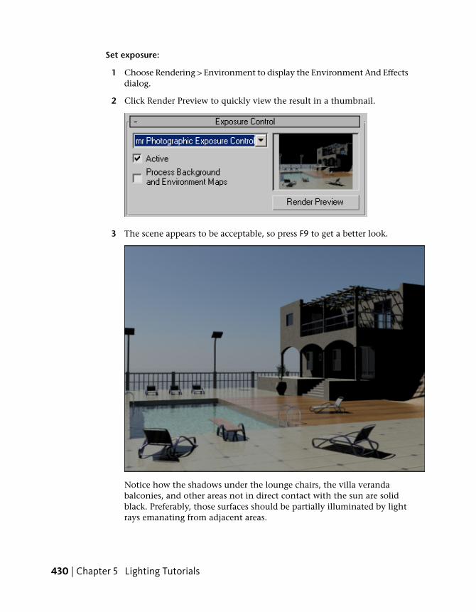
1 Choose Rendering > Environment to display the Environment And Effectsdialog.
2 Click Render Preview to quickly view the result in a thumbnail.
3 The scene appears to be acceptable, so press F9 to get a better look.
Notice how the shadows under the lounge chairs, the villa verandabalconies, and other areas not in direct contact with the sun are solidblack. Preferably, those surfaces should be partially illuminated by lightrays emanating from adjacent areas.
430 | Chapter 5 Lighting Tutorials

The Final Gather option in the Rendered Frame > Include in Render groupensures that these shaded areas receive light from neighboring surfaces.By default, Final Gather is on, but you turned it off earlier so you couldsee the impact this option can have on a scene.
4 In the Rendered Frame window make a clone of the image.
5 In the Include In Render group, turn Final Gather back on and renderyour scene again.
Scene shadows are much improved, but the regions behind the windowsand doorways of the villa remain unnaturally dark. In the next lesson,you will learn how to solve this problem by taking some of the outdoorlight and directing it into the building.
Using Sky Portal and Photographic Exposure Control
Sky Portal is a light object that gathers the sky light (as opposed to directsunlight) generated by the daylight system. It then directs the light flowthrough selected objects, such as doors, glass doors, and windows, so theinterior of buildings can be illuminated.
Add the Sky Portal:
1 Continue working on your own scene file or open the scene filemed-villa-lighting-skyportals.max.
2 Activate the Camera-Terrace viewport, press F9 to render thescene, and in the Rendered Frame Window, make a clone of the image.
3 On an empty area of the main toolbar, right-click and choose Layers fromthe pop-up menu.
Using Sky Portal and Photographic Exposure Control | 431
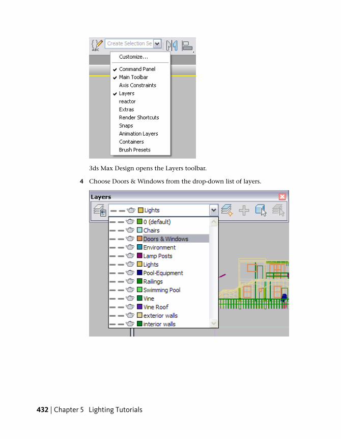
3ds Max Design opens the Layers toolbar.
4 Choose Doors & Windows from the drop-down list of layers.
432 | Chapter 5 Lighting Tutorials

5 Click Select Objects In Current Layer button to select the doorsand windows.
6 Right-click any viewport and choose Isolate Selection from the quadmenu to display only the selected objects.
7 Activate the camera viewport, press P to switch toPerspective view, then navigate with Pan and Field-Of-View until all thewindows are clearly in view.
8 Rotate the view so that the windows and doors face you, as shownin the next illustration.
9 Press Alt + W to maximize the Perspective view, then press F4 to view theunderlying geometry of each object.
10 On the Create panel, click Lights.
11 On the Object Type rollout, click mr Sky Portal, then turn on Autogrid.
Using Sky Portal and Photographic Exposure Control | 433

12 In the Perspective view, create the first Sky Portal by dragging diagonallyfrom the lower-left corner of any window to the upper-right corner, untilthe entire opening is covered.
13 Repeat the previous step for every door and window object in the scene,except for the PivotDoor02 object (it is second from the right in theupper-right corner of the viewport).
14 Rotate the Perspective view so that the windows and doors arevisible from their sides, as shown in the next illustration.
434 | Chapter 5 Lighting Tutorials
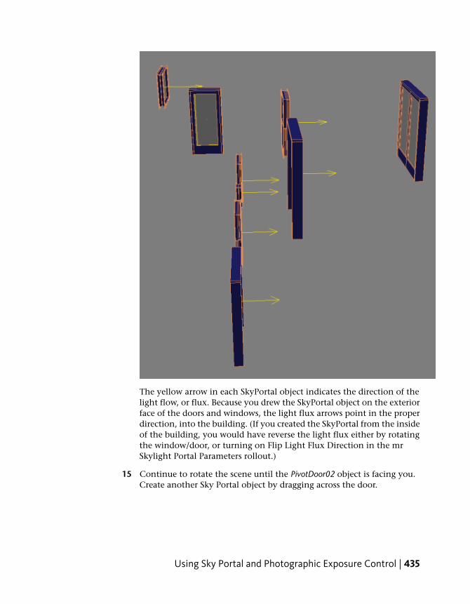
The yellow arrow in each SkyPortal object indicates the direction of thelight flow, or flux. Because you drew the SkyPortal object on the exteriorface of the doors and windows, the light flux arrows point in the properdirection, into the building. (If you created the SkyPortal from the insideof the building, you would have reverse the light flux either by rotatingthe window/door, or turning on Flip Light Flux Direction in the mrSkylight Portal Parameters rollout.)
15 Continue to rotate the scene until the PivotDoor02 object is facing you.Create another Sky Portal object by dragging across the door.
Using Sky Portal and Photographic Exposure Control | 435

16 Rotate the scene one last time so that the sides of the doors andwindows are visible, as shown in the next illustration. The PivotDoor02object should have its light flux direction pointed in the correct direction:into the room from the opposite side of the building.
17 Select any Sky Portal object you created by clicking its yellow light fluxarrow.
436 | Chapter 5 Lighting Tutorials

18 On the Modify panel > mr Skylight Portal Parameters rollout,you can increase the Multiplier value to boost the amount of lighttransmitted by the Sky Portal. For now however, leave the Multiplier setto 1.0.
Ordinarily, you would now go to the Shadows group and turn off theshadows option, because you do not necessarily need interior shadowsfor an exterior shot when viewed from a distance. Also, turning offShadows helps to reduce render time.
19 However, rather than turn off shadows for each Sky Portal individually,from the main menu choose Tools > Light Lister. In the Light Lister dialog> Shadows column, turn off shadows for each of the Sky Portals in thelist.
20 Close the Light Lister.
21 Click Exit Isolation Mode.
If a Select Camera dialog appears, choose Camera-Terrace and then clickOK. Otherwise, click the Perspective viewport label and choose Cameras> Camera-Terrace.
Using Sky Portal and Photographic Exposure Control | 437
22 Press F4 to return to regular shading mode.
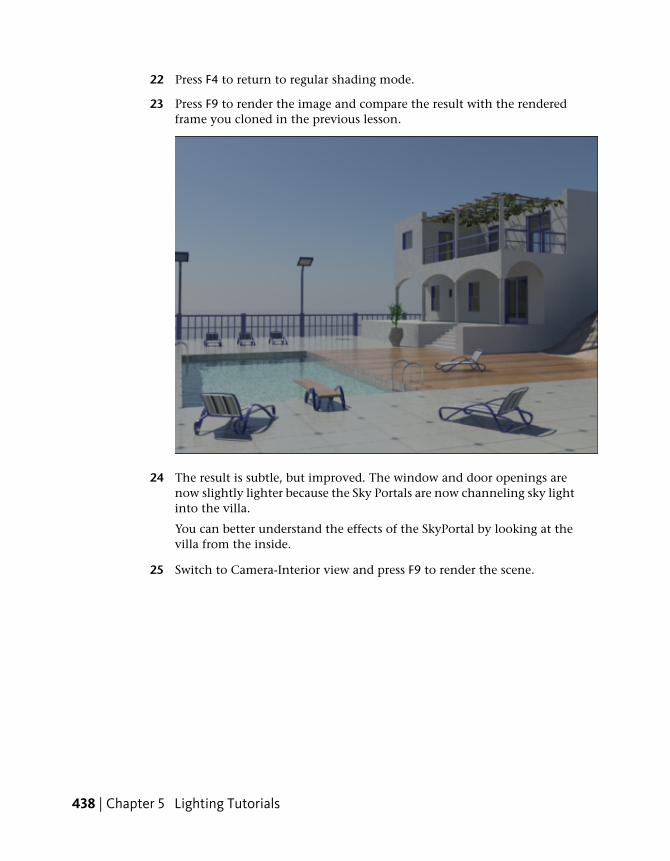
23 Press F9 to render the image and compare the result with the renderedframe you cloned in the previous lesson.
24 The result is subtle, but improved. The window and door openings arenow slightly lighter because the Sky Portals are now channeling sky lightinto the villa.
You can better understand the effects of the SkyPortal by looking at thevilla from the inside.
25 Switch to Camera-Interior view and press F9 to render the scene.
438 | Chapter 5 Lighting Tutorials

Because scene exposure is set to outdoor conditions, the outside portionof the scene is properly exposed. But the interior is very dark. You nowneed to adjust the exposure setting to compensate for the lower light ofthe building interior.
Set exposure for interior illumination:
1 In the Rendered Frame Window, click the Environment AndExposure Dialog button to display the Environment And Effects dialog.
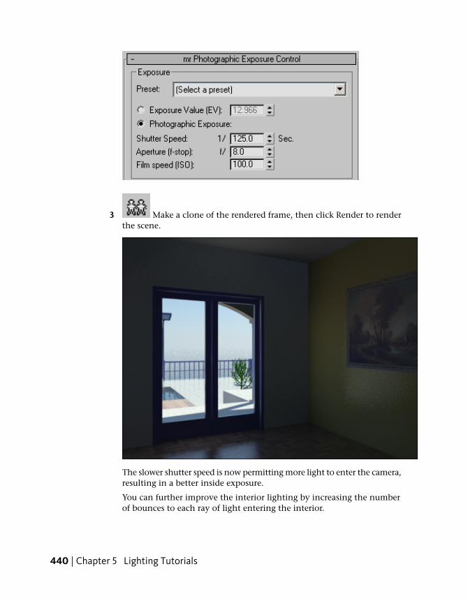
2 On the mr Photographic Exposure Control rollout > Exposure group,make sure Photographic Exposure is chosen, then set Shutter Speed to 1/125.0. Keep the dialog open.
Using Sky Portal and Photographic Exposure Control | 439
3 Make a clone of the rendered frame, then click Render to renderthe scene.
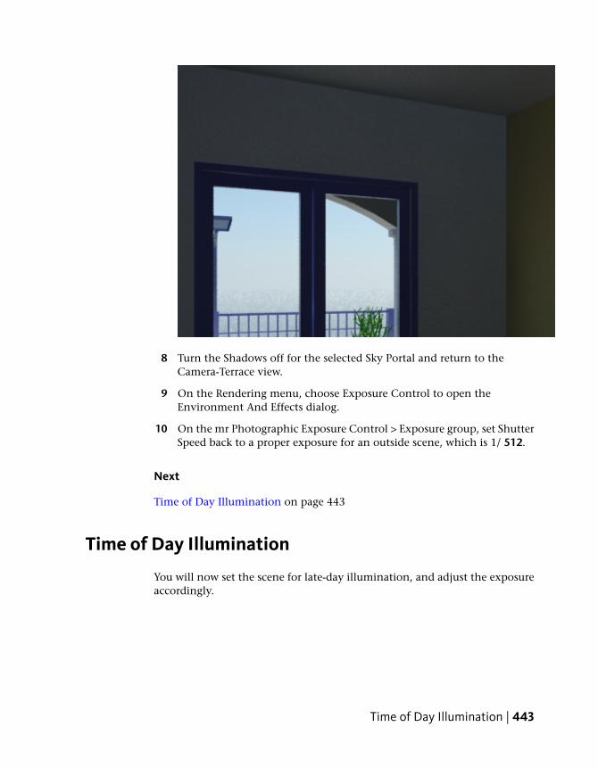
The slower shutter speed is now permitting more light to enter the camera,resulting in a better inside exposure.
You can further improve the interior lighting by increasing the numberof bounces to each ray of light entering the interior.
440 | Chapter 5 Lighting Tutorials

4 Clone the current rendered frame and in the Include In Rendergroup, set FG Bounces to 2.
5 Render the scene and compare the result with the cloned frame.Delete the clone and create a new clone of the most recent render.
Using Sky Portal and Photographic Exposure Control | 441

6 If you wish, you can take things further by dragging the Final GatherPrecision and Image Precision slider bars to the right. Keep in mind thatany such adjustments will affect render speed.
For this interior scene, it is appropriate for the door’s Sky Portal to castshadows. This is because room illumination would ordinarily be affectedby shadows cast by the door frame.
7 Select the Sky Portal object by its gizmo in the center of the door. On themr Skylight Portal Parameters rollout, turn Shadows on, then render thescene.
If you compare the result with the cloned render, you will see a subtledifference in the area where the ceiling and the facing wall meet, as wellas the corner where the two walls meet. The dark corners in the latestrender are thicker, caused by the shadows cast by the door frame.
442 | Chapter 5 Lighting Tutorials
8 Turn the Shadows off for the selected Sky Portal and return to theCamera-Terrace view.
9 On the Rendering menu, choose Exposure Control to open theEnvironment And Effects dialog.
10 On the mr Photographic Exposure Control > Exposure group, set ShutterSpeed back to a proper exposure for an outside scene, which is 1/ 512.
Next
Time of Day Illumination on page 443
Time of Day Illumination
You will now set the scene for late-day illumination, and adjust the exposureaccordingly.
Time of Day Illumination | 443

Change the time of day:
1 Render the scene and make a clone of the result.
2 Select the Daylight object (the sun object, not the compassrose), then go to the Motion panel.
3 On the Control Parameters rollout > Time group > Hours and Mins spinnerboxes, set the time to 18 and 30 respectively (6:30 PM, or 1830 hours).
4 Press F9 to see the result.
The scene is fairly dark, but you can improve this by adjusting theexposure to a setting more appropriate for this time of day.
5 Click the Environment And Exposure Dialog button to displaythe Environment And Effects dialog.
444 | Chapter 5 Lighting Tutorials

6 On the mr Photographic Exposure Control > Exposure group, ShutterSpeed is set to a proper exposure for a camera angle facing the sun.However, you can increase the amount of light entering the scene byadjusting the camera lens aperture.
7 In the Exposure group, set Aperture to 5.6.
8 Render the scene and make a clone of the result.
The overall illumination is much improved, although the outline of thesun disc is lost.
Create a Sunset Exposure:
Here, you will adjust scene exposure so that objects are convincinglyilluminated by the setting sun.
1 On the Control Parameters rollout > Time group > Hours and Mins spinnerboxes, set the time to 19 and 40 mins respectively (7:40 PM, or 1940hours).
Time of Day Illumination | 445
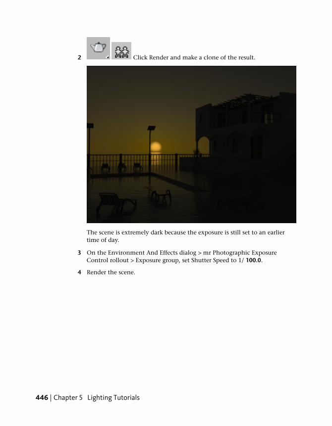
2 Click Render and make a clone of the result.
The scene is extremely dark because the exposure is still set to an earliertime of day.
3 On the Environment And Effects dialog > mr Photographic ExposureControl rollout > Exposure group, set Shutter Speed to 1/ 100.0.
4 Render the scene.
446 | Chapter 5 Lighting Tutorials

The mr Physical Sky shader produces a vivid sky gradient, and detailsaround the pool are much more apparent.
5 Take a look at the two other rendered frames representing the same sceneat 3 PM and 6:30 PM to see how you used mental ray exposure controlsto effectively create three distinctive moods.
Summary
You can create a daylight system to simulate real-world outdoor lightingconditions at any time of day, at any location on the planet. mental ray offersa range of presets that define proper exposure settings for specific lightingconditions, which you can adjust manually as needed. A Sky Portal object canalso be added to channel daylight into doorways and windows of structures,to enhance their interior illumination.
Time of Day Illumination | 447
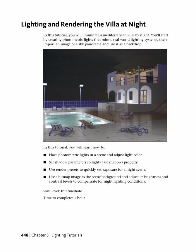
Lighting and Rendering the Villa at NightIn this tutorial, you will illuminate a mediterranean villa by night. You’ll startby creating photometric lights that mimic real-world lighting systems, thenimport an image of a sky panorama and use it as a backdrop.
In this tutorial, you will learn how to:
■ Place photometric lights in a scene and adjust light color.
■ Set shadow parameters so lights cast shadows properly.
■ Use render presets to quickly set exposure for a night scene.
■ Use a bitmap image as the scene background and adjust its brightness andcontrast levels to compensate for night lighting conditions.
Skill level: Intermediate
Time to complete: 1 hour
448 | Chapter 5 Lighting Tutorials

Adding Photometric Lights
You will start by adding incandescent, halogen, and fluorescent lights, whosereal-world properties will illuminate the night scene.
Create a group of recessed lights and set proper exposure:
1 On the Quick Access toolbar, click the Open File button, navigateto the \scenes\lighting_and_rendering\med_villa folder, then open the scenefile med-villa-lighting-start.max.
2 Activate the Top viewport and zoom in to the three ceiling fixtures inthe lower verandah, as shown in the next illustration.
3 Continue to zoom in to the far left fixture until it is clearly in view.
Adding Photometric Lights | 449

4 On the Create panel, choose Lights.
The lights panel is automatically set to Photometric, meaning that anylight you create in this category will exhibit real-world behavior in termsof light attenuation, distribution, color, and so on.
5 On the Object Type rollout, click Free Light.
6 Click once on the center of the fixture to create the light object, thenright-click to end object creation.
By default, the light object is created on the surface plane of the scene.
450 | Chapter 5 Lighting Tutorials
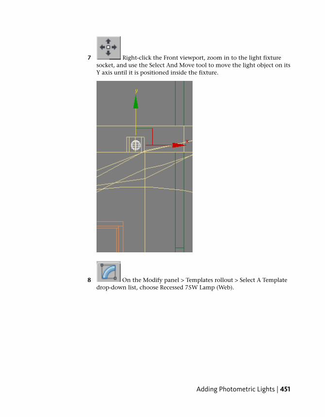
7 Right-click the Front viewport, zoom in to the light fixturesocket, and use the Select And Move tool to move the light object on itsY axis until it is positioned inside the fixture.
8 On the Modify panel > Templates rollout > Select A Templatedrop-down list, choose Recessed 75W Lamp (Web).
Adding Photometric Lights | 451

Values in the rollouts below Templates are set to match the real-worldproperties of the selected light. These properties can be customized asneeded.
9 Zoom out until the light fixture to the right is visible.
10 Hold down Shift and use the Select And Move tool to drag thelight object on its X axis until it is placed inside the neighboring lightfixture, as shown in the next illustration. In the Clone Options dialog >Object group, turn on Instance. Set Number Of Copies to 2, and thenclick OK.
452 | Chapter 5 Lighting Tutorials

11 Activate the Camera-Terrace viewport and press F9 to render the scene.
The image is completely black because the default exposure settings in3ds Max Design are not suitable for the such a dimly lit scene.
12 In the Rendered Frame Window, click the Environment AndExposure Dialog button.
13 The Environment And Effects dialog > Exposure Control rolloutdrop-down list shows that exposure is properly set to the mental ray mrPhotographic Exposure Control, but the default shutter speed and aperturesettings are wrong. This can be easily corrected by choosing theappropriate exposure preset.
Adding Photometric Lights | 453

14 From the mr Photographic Exposure Control rollout > Exposure group >Preset drop-down list, choose Physically Based Lighting, OutdoorNighttime.
The preset has decreased the shutter speed from 1/125 to 1/0.125, anddoubled the aperture size to from f16 to f8. These exposure settings aremore appropriate for a nighttime scene.
15 Press F9 to render the scene.
454 | Chapter 5 Lighting Tutorials

The image is much improved, but there are shading anomalies under theright-most arch of the verandah.
16 Clone the current rendered frame and in the Rendered FrameWindow > Include In Render group turn on Final Gather, set Bounces to2, and then render the scene again.
17 Compare the two rendered images. The added number of light ray bounceshas increased light intensity, and removed the more obvious sceneartifacts.
Adding Photometric Lights | 455

Above: The porch rendered with no final gather
Below: The porch rendered with final gather, Bounces=2
Add more lights to the building interior and upper balcony:
1 Continue working on your own scene file, or from the \med_villa folder,open the scene file med-villa-lighting-bulbs.max.
2 If you are using a new scene file, press F9 to render the scene.
3 Activate the Top viewport and zoom in to the balcony area and the rightside of the house.
4 On the Create panel, choose Lights.
5 On the Object Type rollout, click Free Light.
456 | Chapter 5 Lighting Tutorials

6 Click once above the door frame as shown below to create the light object,then right-click to end object creation.
7 Right-click the Front viewport and use the Select And Movetool to move the light object on its Y axis until it is positioned just abovethe lower-story window.
Adding Photometric Lights | 457
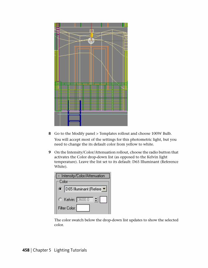
8 Go to the Modify panel > Templates rollout and choose 100W Bulb.
You will accept most of the settings for this photometric light, but youneed to change the its default color from yellow to white.
9 On the Intensity/Color/Attenuation rollout, choose the radio button thatactivates the Color drop-down list (as opposed to the Kelvin lighttemperature). Leave the list set to its default: D65 Illuminant (ReferenceWhite).
The color swatch below the drop-down list updates to show the selectedcolor.
458 | Chapter 5 Lighting Tutorials
NOTE You could also have set light object color by specifying its lighttemperature in the Kelvin spinner. In degrees Kelvin, light color varies from1000 (pink) to 20,000 (blue).
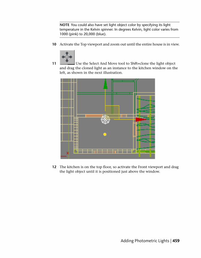
10 Activate the Top viewport and zoom out until the entire house is in view.
11 Use the Select And Move tool to Shift+clone the light objectand drag the cloned light as an instance to the kitchen window on theleft, as shown in the next illustration.
12 The kitchen is on the top floor, so activate the Front viewport and dragthe light object until it is positioned just above the window.
Adding Photometric Lights | 459
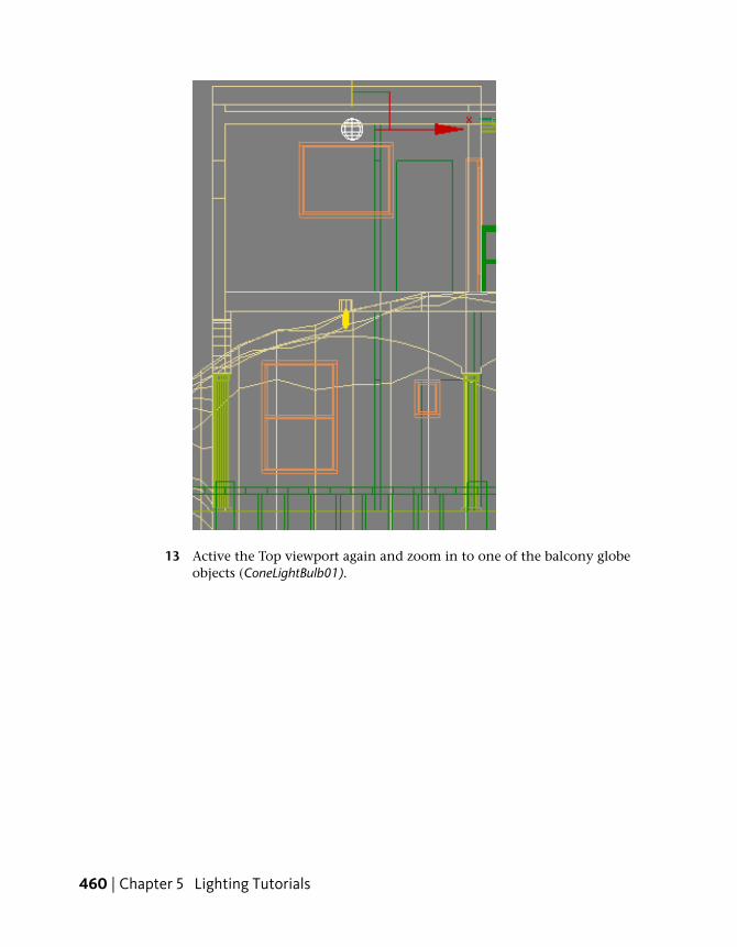
13 Active the Top viewport again and zoom in to one of the balcony globeobjects (ConeLightBulb01).
460 | Chapter 5 Lighting Tutorials

14 On the Create panel, choose Lights.
15 On the Object Type rollout, click Free Light.
16 Click anywhere around the globe to place the light. Its exact position isnot important.
17 On the main toolbar, choose the Align tool, then selectConeLightBulb01.
18 On the Align Selection dialog > Align Selection group, turn on X, Y, andZ Position, and choose Center for both Current Object and Target Object.Click OK.
Adding Photometric Lights | 461

This aligns the center of the light object with the light fixture.
Keep in mind that because the light is set to cast shadows, the object itis placed in must include material transparent enough to have light passthrough. Otherwise, rays from the light object will strike the inside ofthe object it is enclosed in, and travel no farther.
19 Go to the Modify panel > Templates rollout and choose 100W Bulb.
462 | Chapter 5 Lighting Tutorials

Keep in mind that the light you choose in this list possesses the sameproperties as a real-world light, and must therefore be appropriate for thearea it is intended to illuminate.
In terms of light attenuation, for example, for every 10 meters distancetravelled, light intensity from this 100-Watt bulb will drop off to 1/100thof its initial strength.
20 In Top view, zoom out until the second balcony globe to the right isvisible.
21 Use the Select And Move tool + Shift to reposition the light asan instance to a point near ConeLightBulb02.
22 Align the cloned light object just as you did the first light object.
23 Make a clone of the currently rendered frame. Activatethe Camera-Terrace viewport, then render the scene.
24 Compare the two rendered images.
Adding Photometric Lights | 463

Because you used the default color for the 100W bulb light objects, theupper balcony is bathed in a yellowish light. Also, light is now visiblefrom the door and windows of the two rooms in which light objects wereplaced.
Add halogen lights for the pool:
1 Continue working on your own scene file, or from the \med_villa folder,open the scene file med-villa-lighting-halogen.max.
2 Activate the Top viewport and zoom in to the swimming pool, as shownin the next illustration.
464 | Chapter 5 Lighting Tutorials

3 On the Create panel, choose Lights.
4 On the Object Type rollout, click Free Light.
5 Click once to place the light object at the inner edge of the pool as shownin the next illustration, then right-click to end object creation.
Adding Photometric Lights | 465

Be sure to reposition the light so it is slightly away from the pool wall.
6 Right-click the Front viewport and use the Select And Movetool to move the light object on its Y axis until it is positioned at the midpoint between the floor of the pool and the waterline.
7 On the Modify panel > Templates rollout, choose 80W HalogenBulb.
The default color for this type of light is 2900 degrees Kelvin, whichproduces a yellowish hue. A whitish-blue color is preferable, so you willnow modify the light’s Kelvin value accordingly.
466 | Chapter 5 Lighting Tutorials

8 On the Intensity/Color/Attenuation rollout > Color group, set the Kelvinvalue to 8000.0.
9 Use the Select And Move tool to Shift+clone the light object atthe mid point of the pool. In the Clone Options dialog > Object group,turn on Instance and set Number Of Copies to 2.
10 Activate the Top viewport, then Ctrl+select the three light objects andposition their instances at the opposite side of the pool.
Adding Photometric Lights | 467
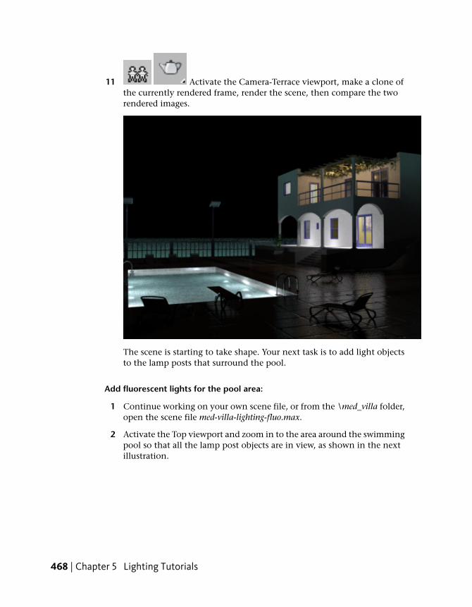
11 Activate the Camera-Terrace viewport, make a clone ofthe currently rendered frame, render the scene, then compare the tworendered images.
The scene is starting to take shape. Your next task is to add light objectsto the lamp posts that surround the pool.
Add fluorescent lights for the pool area:
1 Continue working on your own scene file, or from the \med_villa folder,open the scene file med-villa-lighting-fluo.max.
2 Activate the Top viewport and zoom in to the area around the swimmingpool so that all the lamp post objects are in view, as shown in the nextillustration.
468 | Chapter 5 Lighting Tutorials

3 Press H and select LampPost01 from the Select From Scene dialog.
NOTE If the dialog highlights all six lamp posts, choose Select > SelectDependents to turn off this option.
4 Right-click the viewport and choose Isolate Selection from the quad menu.
Adding Photometric Lights | 469

5 Activate the Camera-Terrace viewport and press P to display Perspectiveview.
6 Click Zoom Extents to get a closer look at the lamp post. Continueto zoom in until the light panel is clearly in view.
7 Zoom in to the lamp post object in the Front and Left viewports as well.
8 On the Create panel, choose Lights.
9 On the Object Type rollout, click Free Light and turn on AutoGrid.
10 In Perspective view, click once in the center of the light panel to placethe light object on its surface. Turn off AutoGrid when you’re done.
470 | Chapter 5 Lighting Tutorials
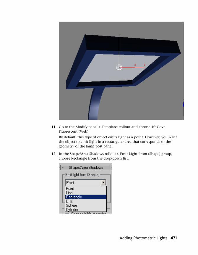
11 Go to the Modify panel > Templates rollout and choose 4ft CoveFluorescent (Web).
By default, this type of object emits light as a point. However, you wantthe object to emit light in a rectangular area that corresponds to thegeometry of the lamp post panel.
12 In the Shape/Area Shadows rollout > Emit Light From (Shape) group,choose Rectangle from the drop-down list.
Adding Photometric Lights | 471

13 Drag the Length and Width spinner arrows until the rectangular boundingbox matches the dimensions of the lamp post light panel.
Use the Top and Left viewports to check your work. Use the Select AndMove tool to adjust light object position if you need to.
NOTE Before you move the light, go to the main toolbar and choose Localas the reference coordinate system.
14 Activate the Front viewport and use the Select And Move toolto move the light object downward slightly, towards the lower surfaceof the fixture.
472 | Chapter 5 Lighting Tutorials

15 Click Exit Isolation Mode, click the Perspective viewport label and chooseCameras > Camera-Terrace.
16 Activate the Top viewport and use the Select And Move tool toShift+clone the light object to the neighboring lamp post, as shown inthe next illustration. (If you changed the reference coordinate system toLocal, change it back to View before you Shift+clone.)
Make the cloned light an instance of the original.
17 Adjust the light object position in the Left viewport.
Adding Photometric Lights | 473

18 In the Top viewport, Ctrl+select the two light objects, and thenclick the Mirror tool.
19 In the Mirror dialog > Mirror Axis group, make sure X is chosen. In theClone Selection group, turn on Instance.
20 In the Top viewport, zoom out and drag the cloned light objects to thelamp posts on the opposite side of the pool.
21 Activate the Front viewport and zoom in to a newly cloned light object.
22 Drag the object on its X axis to the left until it approaches the lowersurface of the fixture.
474 | Chapter 5 Lighting Tutorials
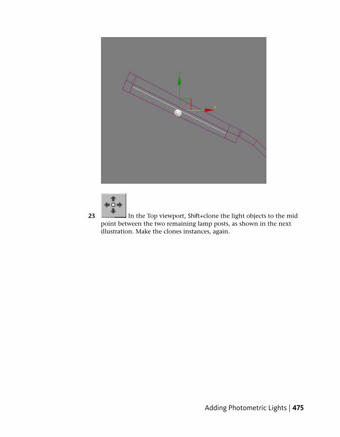
23 In the Top viewport, Shift+clone the light objects to the midpoint between the two remaining lamp posts, as shown in the nextillustration. Make the clones instances, again.
Adding Photometric Lights | 475

24 On the main toolbar, turn on the Angle Snap Toggle.
25 Right-click the Top viewport and choose Rotate from the quad menu.
26 Use the Rotate gizmo to rotate the lights’ position by –90 degrees aboutthe Z axis.
476 | Chapter 5 Lighting Tutorials

27 Move the lights on their Y axis until they are in line with thetwo remaining lamp posts, as shown in the next illustration.
28 Select each light individually and move them on their X axisuntil they are repositioned inside the remaining two lamp posts.
29 Activate the Left viewport, zoom in to one of the light objects you justrepositioned, and drag on its X axis until it is near the outer edge of thefixture. Repeat for the other light object.
30 Activate the Camera-Terrace viewport and render the scene.
Adding Photometric Lights | 477

With the latest addition of these light objects, you will notice that thetime it takes to render the scene has increased considerably.
The area around the pool is now illuminated, but the scene remainsunder-lit. The intensity of the fluorescent light objects needs someadjustment.
Fine-tune the fluorescent illumination:
The fluorescent light objects you created for the pool deck emit a light intensitythat corresponds to their product specifications. However, you have the optionof overriding this setting as needed. Here, you will increase the intensity toprovide added illumination.
1 Select one of the fluorescent light objects.
2 On the Modify panel > Dimming group, double the Resulting Intensityfrom 100 to 200.0 percent.
478 | Chapter 5 Lighting Tutorials

3 Activate the Camera-Terrace viewport and press F9 to render the scene.
Because the light objects were cloned as instances, all lights are affectedby the intensity setting. The amount of available light in the scene hasgreatly increased, rendering the shadows cast by the floor vase and divingboard in greater detail.
The scene is almost complete, but one flaw remains. The frosted glasspanels that cover the lamp posts do not seem to be glowing as brightlyas they should, considering the lamps are the major source of youroutdoor illumination.
Adding Photometric Lights | 479
Make the lamp post fixtures self illuminating:
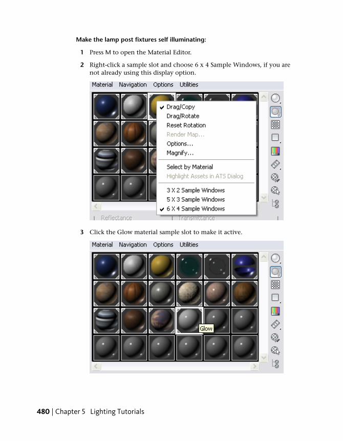
1 Press M to open the Material Editor.
2 Right-click a sample slot and choose 6 x 4 Sample Windows, if you arenot already using this display option.
3 Click the Glow material sample slot to make it active.
480 | Chapter 5 Lighting Tutorials
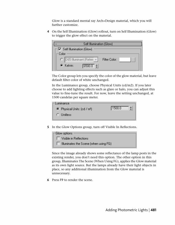
Glow is a standard mental ray Arch+Design material, which you willfurther customize.
4 On the Self Illumination (Glow) rollout, turn on Self Illumination (Glow)to trigger the glow effect on the material.
The Color group lets you specify the color of the glow material, but leavedefault filter color of white unchanged.
In the Luminance group, choose Physical Units (cd/m2). If you laterchoose to add lighting effects such as glare or halo, you can adjust thisvalue to fine-tune the result. For now, leave the setting unchanged, at1500 candelas per square meter.
5 In the Glow Options group, turn off Visible In Reflections.
Since the image already shows some reflectance of the lamp posts in theexisting render, you don’t need this option. The other option in thisgroup, Illuminates The Scene (When Using FG), applies the Glow materialas its own light source. But the lamps already have their light objects inplace, so any additional illumination from the Glow material isunnecessary.
6 Press F9 to render the scene.
Adding Photometric Lights | 481
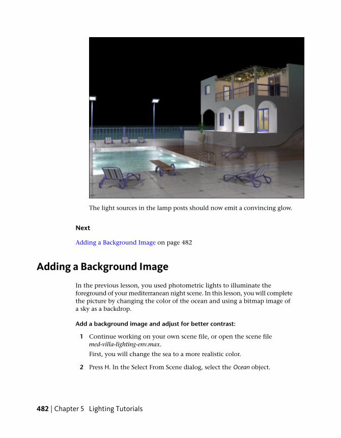
The light sources in the lamp posts should now emit a convincing glow.
Next
Adding a Background Image on page 482
Adding a Background Image
In the previous lesson, you used photometric lights to illuminate theforeground of your mediterranean night scene. In this lesson, you will completethe picture by changing the color of the ocean and using a bitmap image ofa sky as a backdrop.
Add a background image and adjust for better contrast:
1 Continue working on your own scene file, or open the scene filemed-villa-lighting-env.max.
First, you will change the sea to a more realistic color.
2 Press H. In the Select From Scene dialog, select the Ocean object.
482 | Chapter 5 Lighting Tutorials
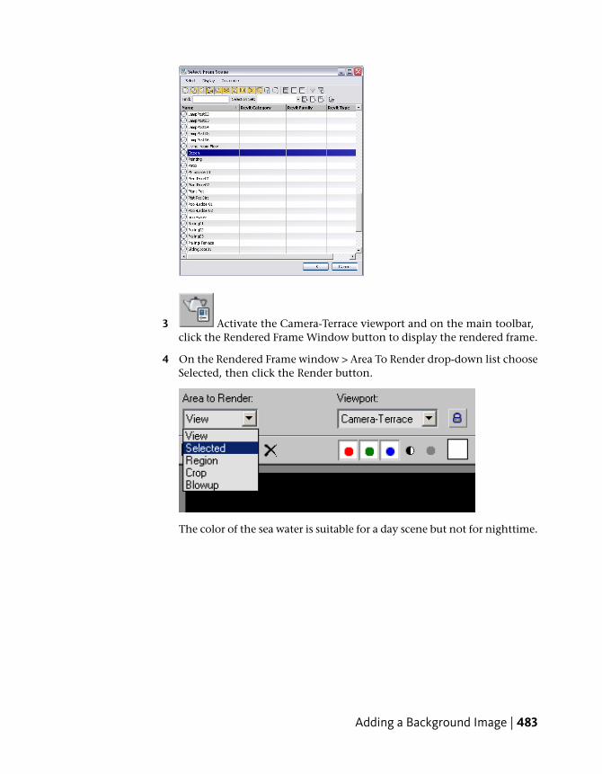
3 Activate the Camera-Terrace viewport and on the main toolbar,click the Rendered Frame Window button to display the rendered frame.
4 On the Rendered Frame window > Area To Render drop-down list chooseSelected, then click the Render button.
The color of the sea water is suitable for a day scene but not for nighttime.
Adding a Background Image | 483

5 Press M to open the Material Editor.
6 Choose the Water - Ocean material, which is located on the top row andfive sample slots to the right.
7 On the Water Material Parameters rollout, Color drop down list, chooseCustom Color.
484 | Chapter 5 Lighting Tutorials

8 Click the Custom Color swatch and on the Color Selector that displays,pick a dark blue color: Red=0.005, Blue=0.025, Green=0.1.
9 Render the ocean. This may take some time, so feel free to cancel therender once you get an idea of the result.
10 On the Area To Render drop-down list, choose View so that the next timeyou render, the entire scene will be included.
11 Click anywhere in the background area of the Camera-Terrace viewport,taking care that no object in the scene is selected.
12 Right click to display the quad menu and choose Hide Unselected.
Now, only the scene background is displayed.
13 From the Rendering menu > Environment > Environment And Effectsdialog > Common Parameters rollout, click the Environment Map button(at present, it says “None”).
14 On the Material/Map Browser, double-click the Bitmap entry.
Adding a Background Image | 485
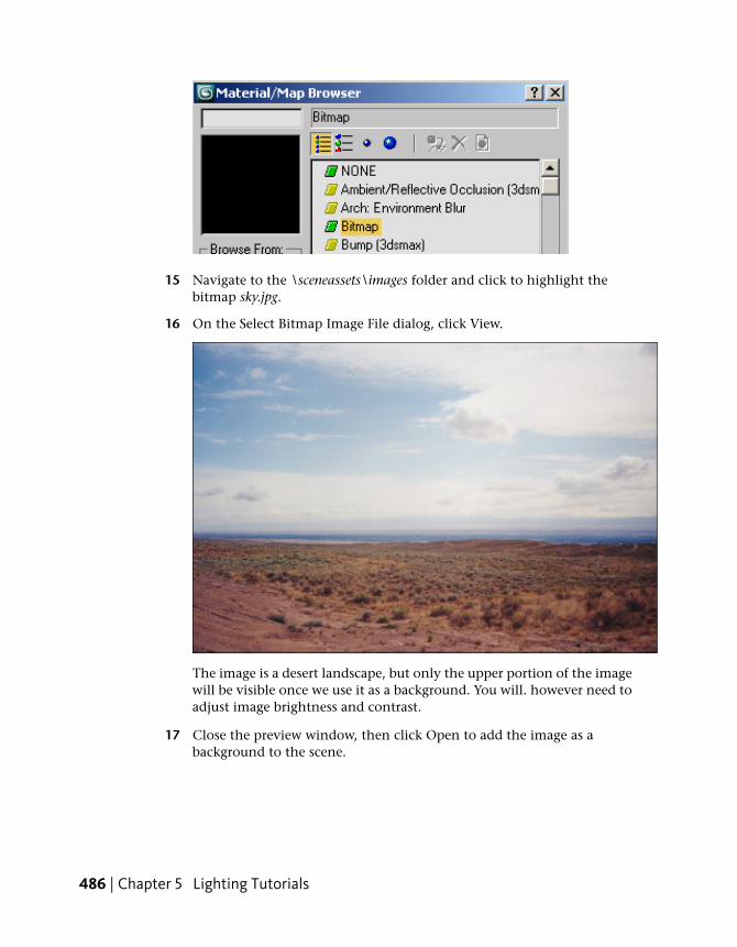
15 Navigate to the \sceneassets\images folder and click to highlight thebitmap sky.jpg.
16 On the Select Bitmap Image File dialog, click View.
The image is a desert landscape, but only the upper portion of the imagewill be visible once we use it as a background. You will. however need toadjust image brightness and contrast.
17 Close the preview window, then click Open to add the image as abackground to the scene.
486 | Chapter 5 Lighting Tutorials

18 Press M to open the Material Editor.
19 Drag the Map button (its label now includes “sky.jpg”) from theEnvironment And Effects dialog, and drop it on an unused sample slotin the Material Editor.
When prompted, choose Instance so the Material Editor shows an instanceof the same map.
20 Close the Environment And Effects dialog, then render the scene.
The scene exposure controls have darkened the image, but the featuresof the clouds are somewhat washed out.
Adding a Background Image | 487

Now you will use the Material Editor to adjust the color and contrast ofthe bitmap to compensate for the low-exposure nighttime scene.
21 On the Material Editor > Output rollout, turn on Enable Color Map.
22 On the Color Map graph, drag the right anchor point downward, asshown in the next illustration.
23 In the Color Map group, click the Add Point button, then clickthe midpoint of the Color Map graph.
488 | Chapter 5 Lighting Tutorials

24 Click the Move button and drag the new map point down andto the right as shown in the next illustration.
25 Render the image again.
The scene might seem too dark at first, but a closer look shows that thecolor map has generated more contrast, emphasizing features that arestill visible in the underexposed image.
Adding a Background Image | 489

26 Right-click any viewport, select Unhide All from the quad menu, thenrender the Camera-Terrace viewport.
This completes the rendering of the villa at night. If you wanted to furtherreduce the amount of anti-aliasing in the scene, you could move theRendered Frame window > Image Precision and Final Gather Precisionsliders one notch to the right. However, increasing these settings requiresa great deal of render time.
Summary
In this tutorial, you learned how to use photometric lights to illuminate anight scene. You specified the color of light sources and defined how shadowswere cast. You also learned how to take a background image, adjust itsbrightness and contrast, and apply it as a background to the night scene.
Daylight Systems and Reflective MaterialsIn this tutorial, you create a daylight system and combine it with a Sky Portalobject and an exposure control preset to illuminate the architectural scene of
490 | Chapter 5 Lighting Tutorials

a retro-style lounge. You will also use the materials editor to bring reflectivesurfaces in the scene to life. The techniques are similar to techniques in UsingSky Portal and Photographic Exposure Control on page 431, but in this tutorial,you are working with a more detailed interior.
In this tutorial, you will learn how to:
■ Use daylight systems to illuminate scenes.
■ Use the Sky Portal object to gather skylight and apply it to an interiorscene.
■ Set scene exposure and apply exposure presets.
■ Set reflective, refractive, and diffusion properties of the Arch & Designmaterial.
■ Set scene illumination based on geographic location, orientation, and timeof day.
Skill level: Intermediate
Time to complete: 1 hour
Adding Daylight Illumination
Start by adding daylight illumination to the lounge scene.
Adding Daylight Illumination | 491

Set up the lesson:
1 On the Quick Access toolbar,click the Open File button, navigate to the\scenes\lighting_and_rendering\lounge_scene folder, then open the scenefile loungebar_tutorial_start.max.
2 Activate the Camera01 viewport, then press F9 to render the scene.
492 | Chapter 5 Lighting Tutorials
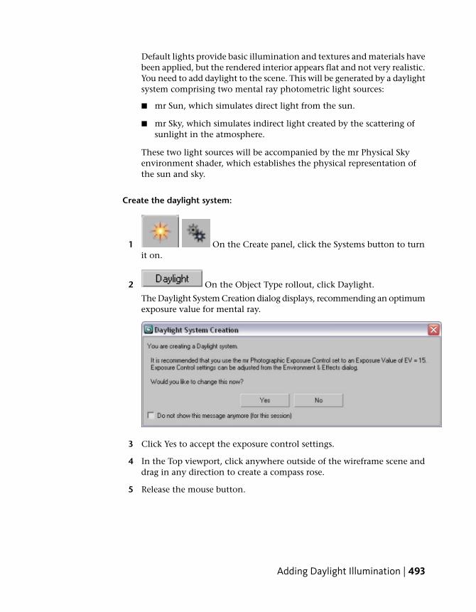
Default lights provide basic illumination and textures and materials havebeen applied, but the rendered interior appears flat and not very realistic.You need to add daylight to the scene. This will be generated by a daylightsystem comprising two mental ray photometric light sources:
■ mr Sun, which simulates direct light from the sun.
■ mr Sky, which simulates indirect light created by the scattering ofsunlight in the atmosphere.
These two light sources will be accompanied by the mr Physical Skyenvironment shader, which establishes the physical representation ofthe sun and sky.
Create the daylight system:
1 On the Create panel, click the Systems button to turnit on.
2 On the Object Type rollout, click Daylight.
The Daylight System Creation dialog displays, recommending an optimumexposure value for mental ray.
3 Click Yes to accept the exposure control settings.
4 In the Top viewport, click anywhere outside of the wireframe scene anddrag in any direction to create a compass rose.
5 Release the mouse button.
Adding Daylight Illumination | 493

As soon as the mouse button is released, the daylight object is createdand the mental ray Sky dialog displays, asking you if you want to createan mr Physical Sky environment map.
The mr Physical Sky environment map is based on a gradient, whoseappearance in the background of a scene will change depending on theposition of the sun at any given time of day. Click Yes to accept the map.
6 Move the mouse to position the sun object above ground level. The heightdoesn’t matter. This simply distances the Daylight object from thecompass rose, and makes it easier to select the sun by a click, later on.
7 Click once to set the Daylight object position, and then right-click to endDaylight creation.
Set the time and location of the light source:
Now you will reposition the Daylight object so that its position in the skycorresponds to the geographic location of the scene.
1 With the Daylight object still selected, go to the Motion panel.
494 | Chapter 5 Lighting Tutorials
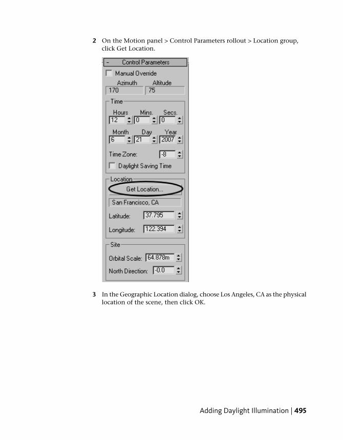
2 On the Motion panel > Control Parameters rollout > Location group,click Get Location.
3 In the Geographic Location dialog, choose Los Angeles, CA as the physicallocation of the scene, then click OK.
Adding Daylight Illumination | 495

The compass rose and Daylight object are repositioned to scenecoordinates that simulate the real-world latitude and longitude of LosAngeles, California.
The Control Parameters > Time group contains controls that let youmodify the date and time of day, which also affects the sun position. Fornow, leave these values at their default settings: noon on June 21st, theyear’s midpoint.
4 Activate the Camera01 viewport and press F9 to render the scene.
496 | Chapter 5 Lighting Tutorials

The scene is too dark: not enough photons are entering the scene to properlyilluminate the interior.
Using a Sky Portal and Exposure Control
You will now use a Sky Portal to gather existing sky lighting and direct itsflow to the interior of the scene.
NOTE The Sky Portal generally requires less render time than the GlobalIllumination option. It is an effective alternative to quickly visualize a scene.
Add the Sky Portal:
1 On the Create panel, click Lights.
2 On the Object Type rollout, click mr Sky Portal, and then turn onAutogrid.
Using a Sky Portal and Exposure Control | 497

3 In the Front viewport, choose Smooth + Highlights, then maximize theviewport by pressing Alt+W.
4 Create the Sky Portal by dragging diagonally from the upper-left cornerof the window to the lower-right corner, until the entire window isencompassed by the box.
The Sky Portal should not be much larger than the window.
5 Right-click to complete creating the Sky Portal, then press Alt+W to viewall four viewports again.
6 With the Sky Portal object still selected, go to the Modify panel.In the mr Skylight Portal Parameters rollout > Shadows group, make sureShadows is on and set Shadow Samples to 32.
Increasing the Shadow Samples value improves shadow accuracy, butalso increases rendering time.
7 Activate the Camera01 viewport and press F9 to render the scene.
498 | Chapter 5 Lighting Tutorials
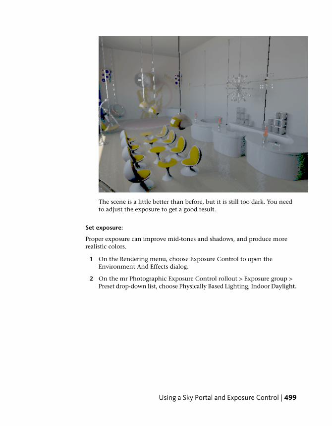
The scene is a little better than before, but it is still too dark. You needto adjust the exposure to get a good result.
Set exposure:
Proper exposure can improve mid-tones and shadows, and produce morerealistic colors.
1 On the Rendering menu, choose Exposure Control to open theEnvironment And Effects dialog.
2 On the mr Photographic Exposure Control rollout > Exposure group >Preset drop-down list, choose Physically Based Lighting, Indoor Daylight.
Using a Sky Portal and Exposure Control | 499
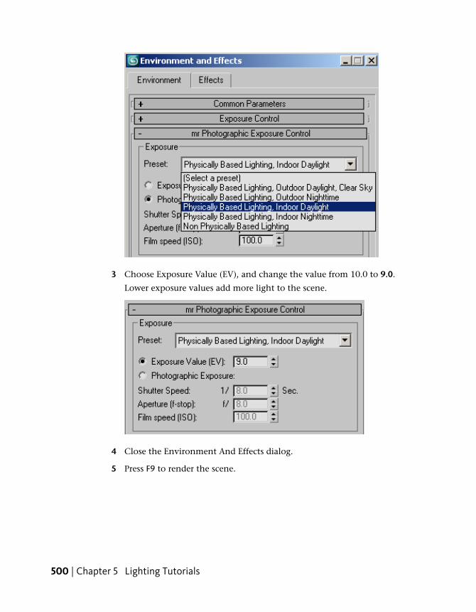
3 Choose Exposure Value (EV), and change the value from 10.0 to 9.0.
Lower exposure values add more light to the scene.
4 Close the Environment And Effects dialog.
5 Press F9 to render the scene.
500 | Chapter 5 Lighting Tutorials

mental ray re-renders the lounge using an exposure preset suitable forindoor illumination. The result is much improved.
Add an Arch & Design material:
Despite all that you’ve done to this point, the scene still looks a little dull. Inthis part of the lesson, you’ll take advantage of the mental ray Arch & Designmaterial to add more interesting lighting effects. You’ll switch the originalwall panel material on the wall behind the bar with that of frosted glass, thenoptimize its reflective attributes.
1 Select any wall panel behind the bar, in any viewport.
2 Press M to open the Material Editor.
Using a Sky Portal and Exposure Control | 501
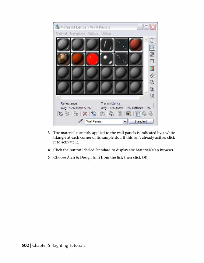
3 The material currently applied to the wall panels is indicated by a whitetriangle at each corner of its sample slot. If this isn’t already active, clickit to activate it.
4 Click the button labeled Standard to display the Material/Map Browser.
5 Choose Arch & Design (mi) from the list, then click OK.
502 | Chapter 5 Lighting Tutorials

6 On the Material Editor > Templates rollout, choose Frosted Glass(Physical).
Using a Sky Portal and Exposure Control | 503
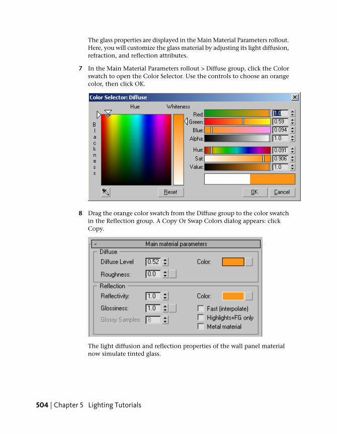
The glass properties are displayed in the Main Material Parameters rollout.Here, you will customize the glass material by adjusting its light diffusion,refraction, and reflection attributes.
7 In the Main Material Parameters rollout > Diffuse group, click the Colorswatch to open the Color Selector. Use the controls to choose an orangecolor, then click OK.
8 Drag the orange color swatch from the Diffuse group to the color swatchin the Reflection group. A Copy Or Swap Colors dialog appears: clickCopy.
The light diffusion and reflection properties of the wall panel materialnow simulate tinted glass.
504 | Chapter 5 Lighting Tutorials

9 Right-click the Refraction group > Transparency spinner arrows to setrefractive transparency to 0.0.
At zero, light will bounce off the material surface rather than penetrateit. This results in more sharply-defined reflected images in the glass.
10 Scroll down to the BRDF rollout.
BRDF, which stands for bidirectional reflectance distribution function, is aproperty that lets the material’s reflectivity be determined by the anglefrom which the object surface is viewed.
11 Choose Custom Reflectivity Function to activate these controls. In the 0deg refl. field, specify a value of 0.5.
Viewing material reflections using the By IOR setting is fine if you areviewing reflective surfaces straight on. The Custom Reflectivity Functionoption is a better choice, however, since it better calculates reflectancefrom the 45-degree position of the camera.
12 Activate the Camera01 viewport and press F9 to render the scene.
Using a Sky Portal and Exposure Control | 505

The newly-applied wall panel material has added considerable interestto the scene.
Changing the Time of Day
Despite having changed the wall panel material to glass, the scene is still fairlydim. In your latest render, notice how the light is cast almost directlydownward, illuminating just the left-most fringe of the lounge floor. This isthe result of two problems: it is high noon in Los Angeles and the architecturalscene is not oriented correctly. In this lesson, you’ll change the scene so thatthe window is facing the proper direction: west. You’ll also reset the time ofday to produce a late-afternoon ambience.
Adjust scene orientation and time of day:
1 In the Top viewport, click the compass rose to select it.
2 On the toolbar, click Select And Rotate.
3 Rotate the compass 90 degrees counterclockwise.
506 | Chapter 5 Lighting Tutorials

The western point of the compass rose should now point downward, sothat the lounge window, where daylight illumination enters the lounge,faces west.
4 On the main toolbar, click the Select Object button, then selectthe Daylight01 object.
5 On the Modify panel > Daylight Parameters rollout, click theSetup button.
Changing the Time of Day | 507

This takes you to the daylight controls on the Motion panel.
6 On the Motion panel > Control Parameters rollout > Time group> Hours spinner controls, click the up-arrow button to increment thehour setting.
508 | Chapter 5 Lighting Tutorials
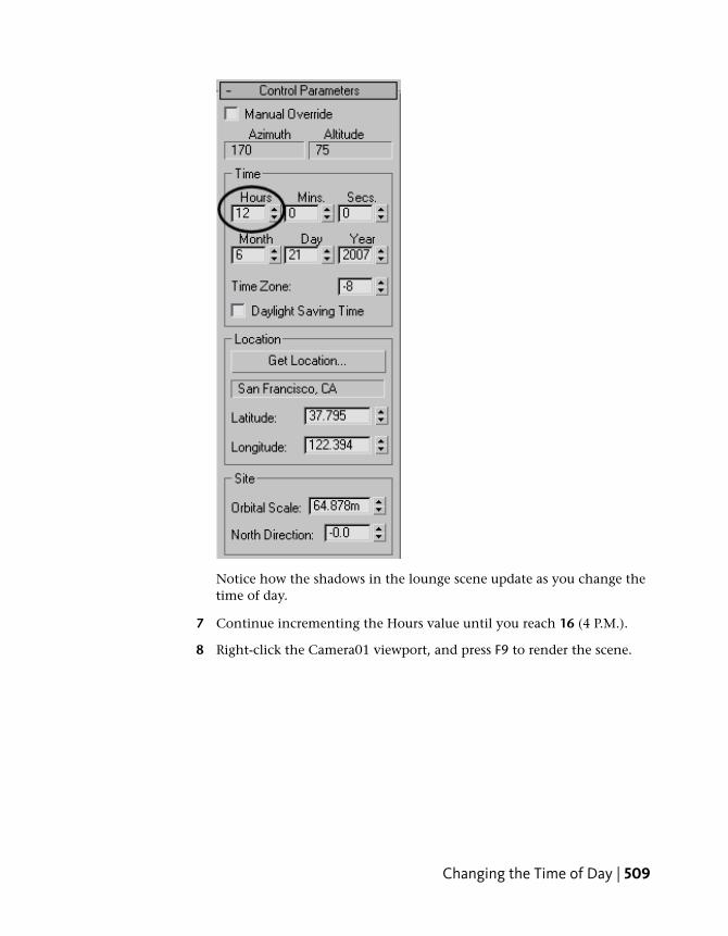
Notice how the shadows in the lounge scene update as you change thetime of day.
7 Continue incrementing the Hours value until you reach 16 (4 P.M.).
8 Right-click the Camera01 viewport, and press F9 to render the scene.
Changing the Time of Day | 509

Add final gather:
Your scene is almost done. All you need to do now is add final gather to betterdistribute light entering the lounge. Final gather generates a specified numberof light bounces.
1 Make sure the Camera01 viewport is active.
2 In the Rendered Frame Window > Include In Render group, move theFinal Gather precision slider to Low and leave Bounces set to its defaultvalue of 2. (More bounces can improve accuracy, but they take longer torender.)
3 Press Render.
510 | Chapter 5 Lighting Tutorials

Your rendered scene should resemble this illustration.
You can compare your result by opening and rendering the scene fileloungebar_tutorial_final.max.
Summary
This tutorial provided another demonstration of the mr Sky Portal, this timein an interior scene that has a lot of shiny, reflective surfaces.
Indoor Lighting AnalysisThe 3ds Max Design lighting analysis feature can help designers and otherspecialists evaluate how interior or exterior space is illuminated at differenttimes of the day, or how interiors are affected by various man-made lightingsystems.
In this tutorial, you will use 3ds Max Design Light Meter objects to evaluatehow light intensity from a daylight source affects the lighting of an indoortennis court.
You will export the Light Meter data to an Excel file, making it available foranalysis by third parties. You’ll then render the scene and overlay the imagewith a layer of Light Meter readings for a more visual representation of lightingintensity.
Indoor Lighting Analysis | 511

In this tutorial, you will learn how to:
■ Use the Lighting Analysis Assistant to prepare a scene for lighting analysis
■ Create a daylight system
■ Use a weather data file to set daylight system light intensity
■ Create Light Meters and adjust their sampling point density
■ Process Light Meters and adjust the range of their color feedback
■ Convert Light Meter data to spreadsheet format
■ Overlay Light Meter data onto a rendered image of the scene
Skill level: Intermediate
Time to complete: 1 hour
Prepare the Scene
The scene consists of an indoor tennis court. Materials have already beenapplied to its surfaces.
512 | Chapter 5 Lighting Tutorials
First, you will create a daylight system. (If the model were imported fromAutoDesk Revit, a daylight system would already be present.) You’ll thenperform a test render to check image quality.
Create a daylight system:
1 On the Quick Access toolbar, click the Open File button, navigateto the \scenes\lighting_and_rendering\lighting_analysis folder, then openthe scene file arena_start.max.
NOTE If a dialog asks whether you want to use the scene’s Gamma And LUTsettings, accept the scene Gamma settings, and click OK. If a dialog askswhether to use the scene’s units, accept the scene units, and click OK.
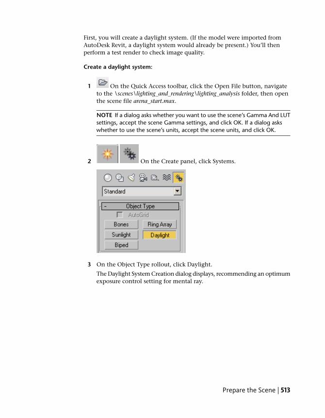
2 On the Create panel, click Systems.
3 On the Object Type rollout, click Daylight.
The Daylight System Creation dialog displays, recommending an optimumexposure control setting for mental ray.
Prepare the Scene | 513

Exposure Control is comparable to the shutter and aperture settings of acamera. It adjusts the brightness and contrast in a rendered image. It doesnot affect the actual amount of lighting in a scene.
4 Click Yes to accept the “mr Photographic” Exposure Control.
5 In the Top viewport, click anywhere over the scene and drag slightly inany direction to create a compass rose.
6 Release the mouse button.
The mental ray Sky dialog opens, asking if you want to automaticallycreate an mr Physical Sky environment map for the background of yourscene.
NOTE 3ds Max Design displays this dialog only if you are using the defaultset of tool options. To revert to this default setting, from the Customize menuchoose Custom UI And Default Switcher, and on the Choose Initial Settingsdialog > Initial Settings For Tools Options, choose DesignVIZ.mentalray.
7 Click Yes.
The sky map is cosmetic, and while it will create a nicely shadedbackground to the scene exterior, it will not affect scene interior lightinglevels in any way.
8 Move the mouse upward to position the daylight object in the sky. Theexact height of the daylight object in the sky is not important, as longas it is above the model. Daylight object height has no affect on scenelighting or rendering.
514 | Chapter 5 Lighting Tutorials

9 Click once to set the Daylight object position.
10 In the Top viewport, right-click to end Daylight creation.
11 Go to the Modify panel, scroll down to the mr Sky AdvancedParameters rollout, and turn off Aerial Perspective.
This option, which simulates atmospheric haze and reduces the visibilityof distant objects, can interfere with lighting analysis.
Prepare the Scene | 515
Do a test render:
1 Activate the camera viewport.
NOTE Lighting analysis is always performed from a camera’s perspective andtherefore requires a camera object in the scene.
2 From the Rendering menu, choose Exposure Control to open theEnvironment And Effects dialog.
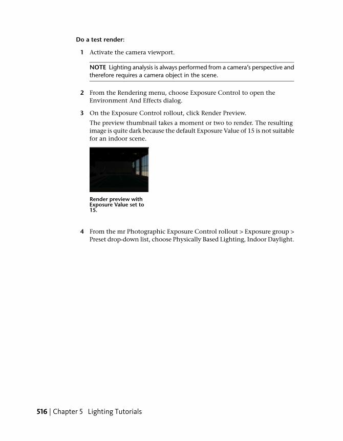
3 On the Exposure Control rollout, click Render Preview.
The preview thumbnail takes a moment or two to render. The resultingimage is quite dark because the default Exposure Value of 15 is not suitablefor an indoor scene.
Render preview withExposure Value set to15.
4 From the mr Photographic Exposure Control rollout > Exposure group >Preset drop-down list, choose Physically Based Lighting, Indoor Daylight.
516 | Chapter 5 Lighting Tutorials
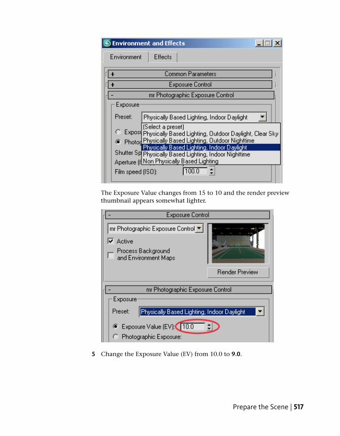
The Exposure Value changes from 15 to 10 and the render previewthumbnail appears somewhat lighter.
5 Change the Exposure Value (EV) from 10.0 to 9.0.
Prepare the Scene | 517
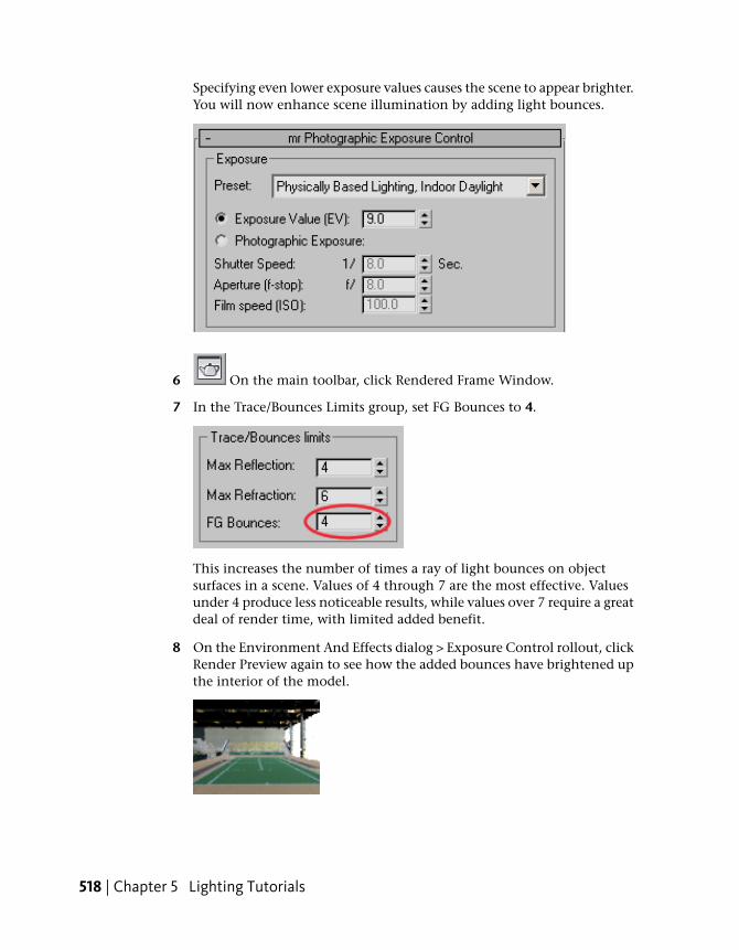
Specifying even lower exposure values causes the scene to appear brighter.You will now enhance scene illumination by adding light bounces.
6 On the main toolbar, click Rendered Frame Window.
7 In the Trace/Bounces Limits group, set FG Bounces to 4.
This increases the number of times a ray of light bounces on objectsurfaces in a scene. Values of 4 through 7 are the most effective. Valuesunder 4 produce less noticeable results, while values over 7 require a greatdeal of render time, with limited added benefit.
8 On the Environment And Effects dialog > Exposure Control rollout, clickRender Preview again to see how the added bounces have brightened upthe interior of the model.
518 | Chapter 5 Lighting Tutorials

9 Click Render (or press F9) to render a full-size frame.
Artifacts present in the scene
The model renders well, but there are some noticeable artifacts on theback wall as well as on the court floor near the stands to the left.
You could improve the render quality by adjusting the Image Precisionand Final Gather Precision sliders in the Rendered Frame Window. Eachslider position represents a preset group of Final Gather settings. In thislesson, however, you will perform your adjustments manually.
10 On the Rendered Frame Window toolbar, click Render Setup.
11 In the Render Setup dialog > Indirect Illumination tab > Final Gatherrollout > Basic group, set Initial FG Point Density to 0.2, Rays Per FGPoint to 150, and Interpolate Over Num FG Points to 50.
Prepare the Scene | 519

These values will eliminate most of the noise artifacts in the scene whileensuring a reasonably fast calculation time.
To learn more about Final Gather and each of its settings, refer to the 3dsMax Design Help.
12 In the Rendered Frame Window make a clone of the rendered image,then press F9 to render again.
This time, your image will take roughly three times as long to render.
13 Compare the two images to see how your edits to Final Gather haveaffected image quality.
Some artifacts remain, but the overall image is much improved.
520 | Chapter 5 Lighting Tutorials
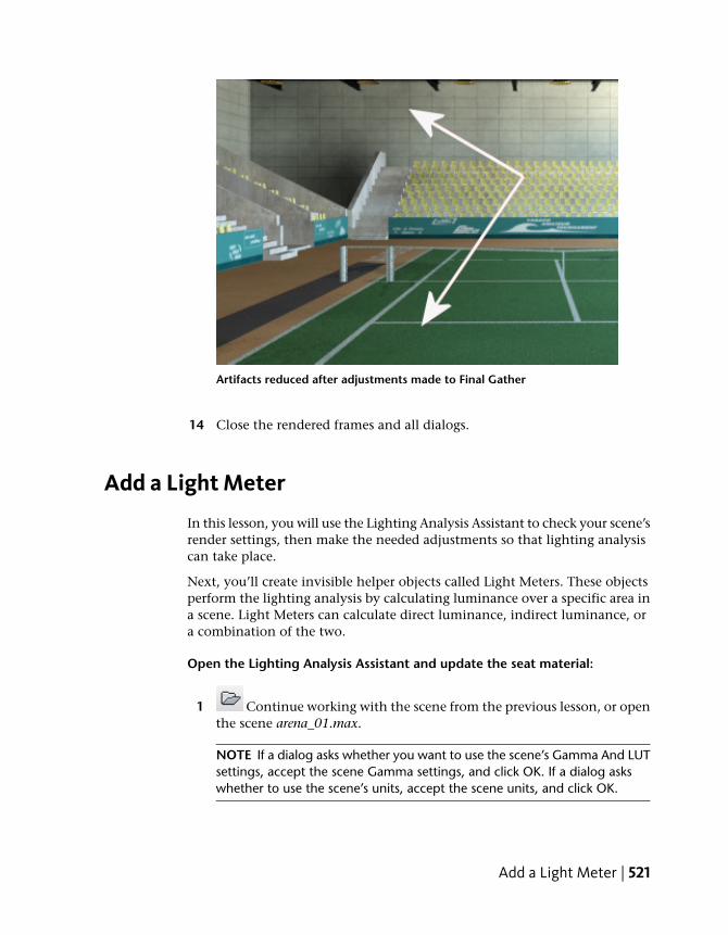
Artifacts reduced after adjustments made to Final Gather
14 Close the rendered frames and all dialogs.
Add a Light Meter
In this lesson, you will use the Lighting Analysis Assistant to check your scene’srender settings, then make the needed adjustments so that lighting analysiscan take place.
Next, you’ll create invisible helper objects called Light Meters. These objectsperform the lighting analysis by calculating luminance over a specific area ina scene. Light Meters can calculate direct luminance, indirect luminance, ora combination of the two.
Open the Lighting Analysis Assistant and update the seat material:
1 Continue working with the scene from the previous lesson, or openthe scene arena_01.max.
NOTE If a dialog asks whether you want to use the scene’s Gamma And LUTsettings, accept the scene Gamma settings, and click OK. If a dialog askswhether to use the scene’s units, accept the scene units, and click OK.
Add a Light Meter | 521
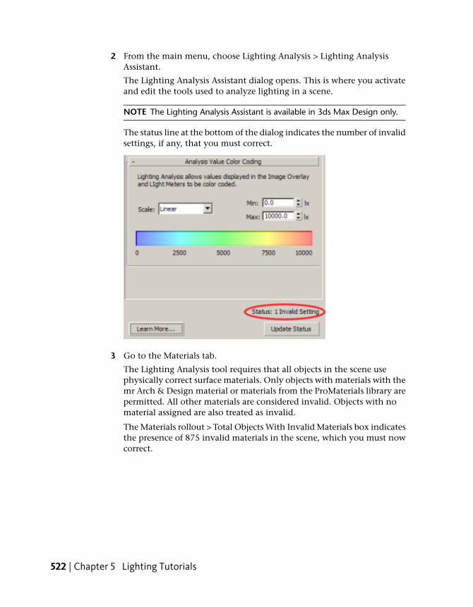
2 From the main menu, choose Lighting Analysis > Lighting AnalysisAssistant.
The Lighting Analysis Assistant dialog opens. This is where you activateand edit the tools used to analyze lighting in a scene.
NOTE The Lighting Analysis Assistant is available in 3ds Max Design only.
The status line at the bottom of the dialog indicates the number of invalidsettings, if any, that you must correct.
3 Go to the Materials tab.
The Lighting Analysis tool requires that all objects in the scene usephysically correct surface materials. Only objects with materials with themr Arch & Design material or materials from the ProMaterials library arepermitted. All other materials are considered invalid. Objects with nomaterial assigned are also treated as invalid.
The Materials rollout > Total Objects With Invalid Materials box indicatesthe presence of 875 invalid materials in the scene, which you must nowcorrect.
522 | Chapter 5 Lighting Tutorials
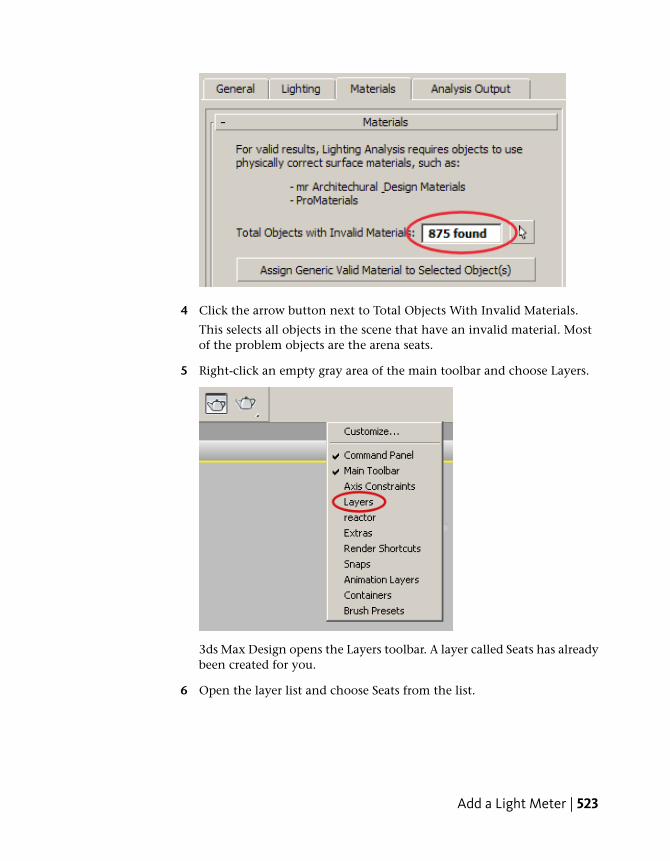
4 Click the arrow button next to Total Objects With Invalid Materials.
This selects all objects in the scene that have an invalid material. Mostof the problem objects are the arena seats.
5 Right-click an empty gray area of the main toolbar and choose Layers.
3ds Max Design opens the Layers toolbar. A layer called Seats has alreadybeen created for you.
6 Open the layer list and choose Seats from the list.
Add a Light Meter | 523

7 On the Layers toolbar, click Select Objects In Current Layer.
All seat objects are selected. The Modify panel shows 874 objects selected,just one short of the 875 total number of objects with invalid materials.
8 Press M to open the Material Editor.
The Seats sample slot is active, indicating that a material has been appliedto the seat objects. However, the Material Editor also indicates that thematerial used is Standard, not physically-based, as is required for lightinganalysis.
524 | Chapter 5 Lighting Tutorials
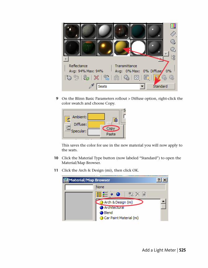
9 On the Blinn Basic Parameters rollout > Diffuse option, right-click thecolor swatch and choose Copy.
This saves the color for use in the new material you will now apply tothe seats.
10 Click the Material Type button (now labeled “Standard”) to open theMaterial/Map Browser.
11 Click the Arch & Design (mi), then click OK.
Add a Light Meter | 525

12 On the Templates rollout, choose Matte Finish from the list.
This gives the material a neutral reflectivity.
13 On the Main Material Parameters rollout > Diffuse group, right-click onthe color swatch and choose Paste.
This copies the color from the Standard material to the Arch & Designmaterial.
14 On the Lighting Analysis Assistant dialog, click Update Status.
526 | Chapter 5 Lighting Tutorials

The Total Objects With Invalid Materials box updates to show only oneremaining object with an invalid material.
Update the grid material:
1 Activate the Top viewport and click Zoom Extents.
2 On the Lighting Analysis Assistant dialog > Materials rollout > TotalObjects With Invalid Materials, click the Arrow button.
The grid object, which is the ground on which the indoor arena stands,is selected.
Add a Light Meter | 527
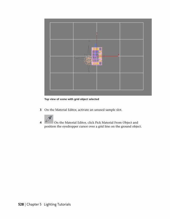
Top view of scene with grid object selected
3 On the Material Editor, activate an unused sample slot.
4 On the Material Editor, click Pick Material From Object andposition the eyedropper cursor over a grid line on the ground object.
528 | Chapter 5 Lighting Tutorials

The eyedropper barrel is empty, indicating that no material exists. If youposition the eyedropper over the arena model it appears full, indicatingthat material is present.
Because the ground object has no material applied to it, it is consideredas having an invalid material.
5 On the Templates rollout, choose Matte Finish from the list.
Add a Light Meter | 529

6 On the Main Material Parameters rollout > Diffuse group, click the colorchip.
7 On the Color Selector, change the Value to 0.2.
530 | Chapter 5 Lighting Tutorials

This gives the material low reflectivity.
8 Click Assign Material To Selection to apply the material to theground object.
9 On the Lighting Analysis Assistant, click Update Status.
The Status line should display “0 Invalid Settings”.
Now that you have the scene properly set up, you must create a LightMeter. For lighting analysis to take place, at least one Light Meter mustbe present in the scene.
10 Close the Material Editor.
Create a Light Meter:
1 From the Layers toolbar > Layers list, choose Light Meters.
Any light meter you now create will be added to this layer for easyselection later on.
2 Press Alt+W to maximize the Top viewport.
3 Zoom in so you can see the floor plan of the arena.
Now you will create a Light Meter for the tennis court area.
4 On the Lighting Analysis Assistant dialog, go to the Analysis Output paneland on the Light Meters rollout, click Create A Light Meter.
Add a Light Meter | 531

5 In the Top viewport, click on the bottom left corner of the tennis courtand drag diagonally until the Light Meter gizmo covers the entire surfaceof the court.
532 | Chapter 5 Lighting Tutorials
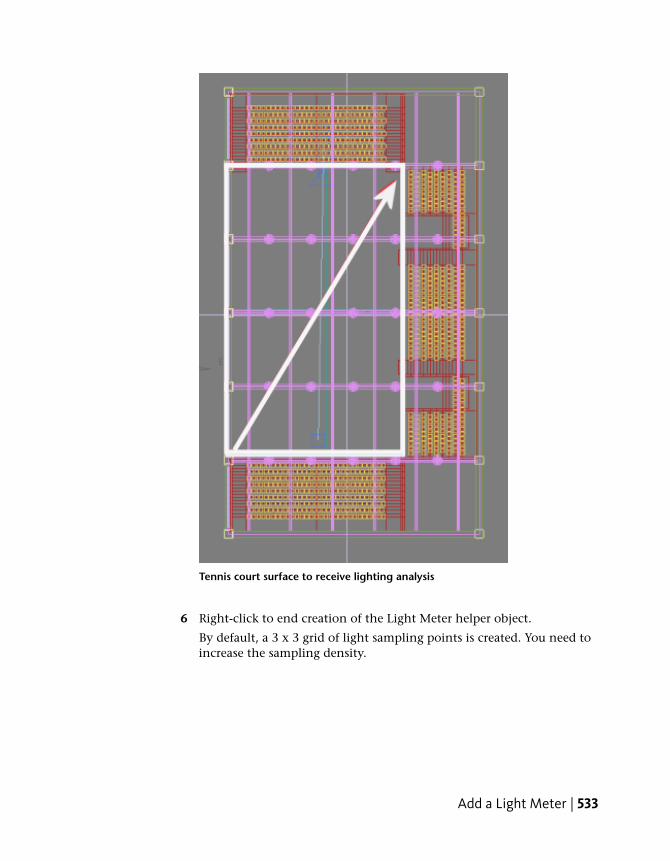
Tennis court surface to receive lighting analysis
6 Right-click to end creation of the Light Meter helper object.
By default, a 3 x 3 grid of light sampling points is created. You need toincrease the sampling density.
Add a Light Meter | 533

7 Press Alt+W to return to a four-viewport view, and in the Modifypanel > Parameters rollout > Dimensions group, set Length Segs to 9 andWidth Segs to 11.
In any viewport, you can see each light sampling point as a verticalpointer. Because Light Meters are helper objects, you can move themaround like any other object in a scene.
8 In the Camera01 viewport, notice how the Light Meter sample pointsappear slightly embedded in the court surface. This might hinder theirability to analyze light, so you need to raise them slightly upward.
Light Meter helper object with sampling points embedded in court surface
534 | Chapter 5 Lighting Tutorials

9 On the main toolbar, click Select And Move, then on the Z axistransform field, type 0.055 and press Enter.
Light Meter helper object after adjustment of its Z-axis position
The ground object is five centimeters thick, so the 0.055 value places thesampling points a half centimeter above it.
Performing Lighting Analysis
Now that you have created a Light Meter and adjusted the distribution of itssampling points in your model, you are ready to use the points to calculatethe lighting intensity.
You will process the Light Meter for midday, then take another reading for aperiod later that day to see how the change in sun position affects lightdistribution in the model interior.
Performing Lighting Analysis | 535
Choose a sky model:
Sky models are a set of luminance distributions that model the sky under arange of conditions, from overcast to clear sky. 3ds Max Design comes withthree available sky models: Haze-Driven, Perez All-Weather, and CIE.
Perez All Weather and CIE are the models best suited to lighting analysis.
1 Continue working with the scene from the previous lesson, or openthe scene arena_02.max.
NOTE If a dialog asks whether you want to use the scene’s Gamma And LUTsettings, accept the scene Gamma settings, and click OK. If a dialog askswhether to use the scene’s units, accept the scene units, and click OK.
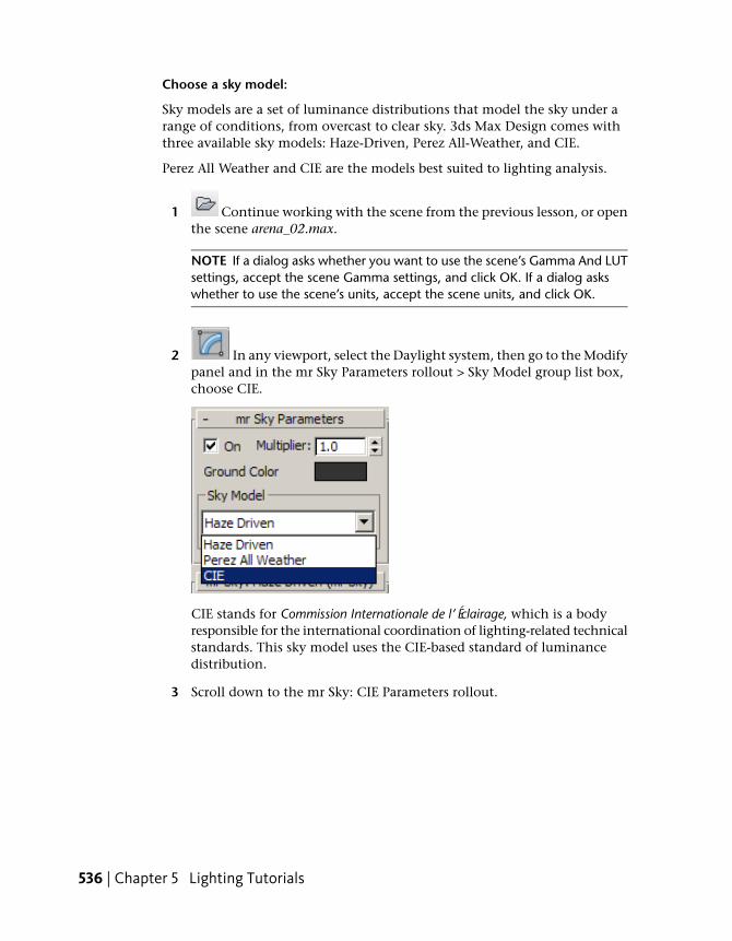
2 In any viewport, select the Daylight system, then go to the Modifypanel and in the mr Sky Parameters rollout > Sky Model group list box,choose CIE.
CIE stands for Commission Internationale de l’Éclairage, which is a bodyresponsible for the international coordination of lighting-related technicalstandards. This sky model uses the CIE-based standard of luminancedistribution.
3 Scroll down to the mr Sky: CIE Parameters rollout.
536 | Chapter 5 Lighting Tutorials
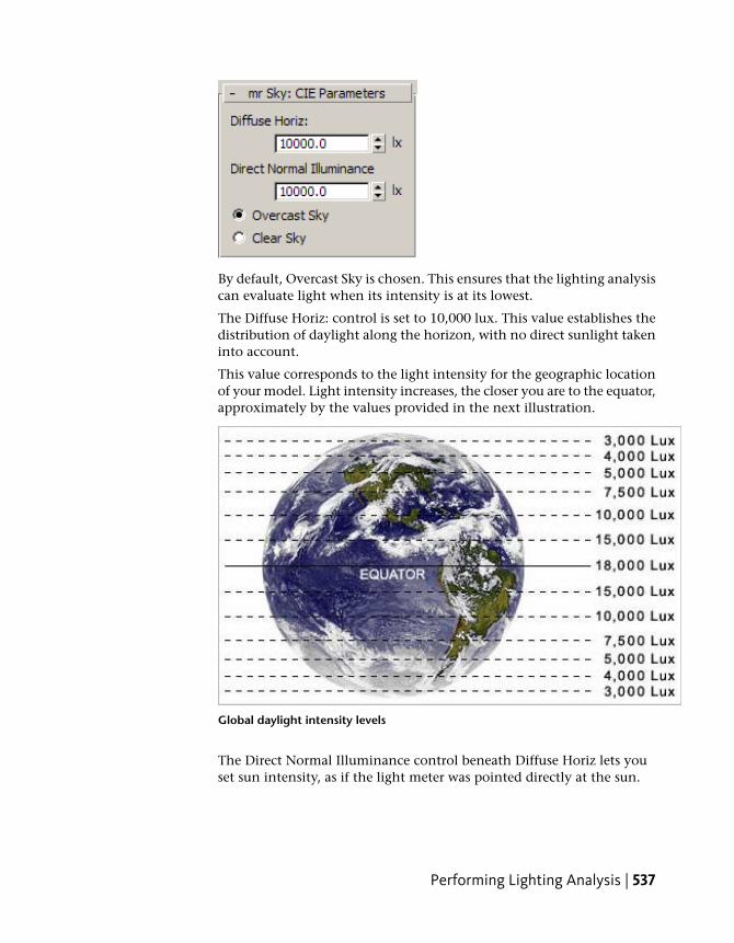
By default, Overcast Sky is chosen. This ensures that the lighting analysiscan evaluate light when its intensity is at its lowest.
The Diffuse Horiz: control is set to 10,000 lux. This value establishes thedistribution of daylight along the horizon, with no direct sunlight takeninto account.
This value corresponds to the light intensity for the geographic locationof your model. Light intensity increases, the closer you are to the equator,approximately by the values provided in the next illustration.
Global daylight intensity levels
The Direct Normal Illuminance control beneath Diffuse Horiz lets youset sun intensity, as if the light meter was pointed directly at the sun.
Performing Lighting Analysis | 537
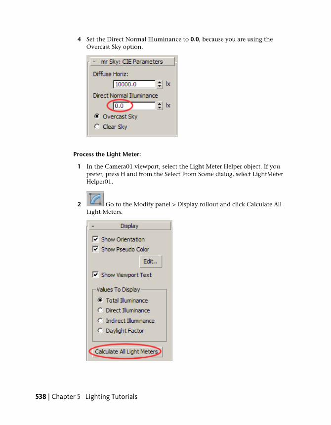
4 Set the Direct Normal Illuminance to 0.0, because you are using theOvercast Sky option.
Process the Light Meter:
1 In the Camera01 viewport, select the Light Meter Helper object. If youprefer, press H and from the Select From Scene dialog, select LightMeterHelper01.
2 Go to the Modify panel > Display rollout and click Calculate AllLight Meters.
538 | Chapter 5 Lighting Tutorials
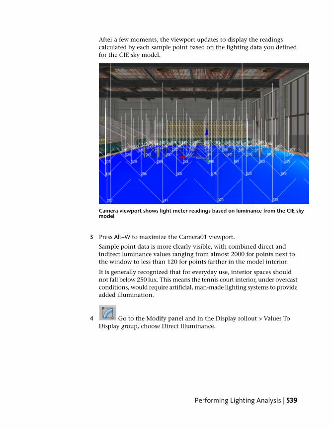
After a few moments, the viewport updates to display the readingscalculated by each sample point based on the lighting data you definedfor the CIE sky model.
Camera viewport shows light meter readings based on luminance from the CIE skymodel
3 Press Alt+W to maximize the Camera01 viewport.
Sample point data is more clearly visible, with combined direct andindirect luminance values ranging from almost 2000 for points next tothe window to less than 120 for points farther in the model interior.
It is generally recognized that for everyday use, interior spaces shouldnot fall below 250 lux. This means the tennis court interior, under overcastconditions, would require artificial, man-made lighting systems to provideadded illumination.
4 Go to the Modify panel and in the Display rollout > Values ToDisplay group, choose Direct Illuminance.
Performing Lighting Analysis | 539

The sample points all return a value of 0 because, being an overcast day,there is no direct sunlight to record.
Light meter readings detect no direct luminance
5 Choose Indirect Illuminance.
The values are identical to those of step 2, because Total Luminancemeasured no direct sunlight.
540 | Chapter 5 Lighting Tutorials
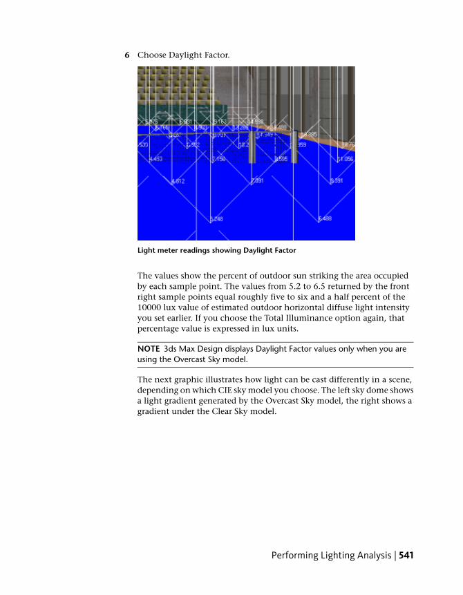
6 Choose Daylight Factor.
Light meter readings showing Daylight Factor
The values show the percent of outdoor sun striking the area occupiedby each sample point. The values from 5.2 to 6.5 returned by the frontright sample points equal roughly five to six and a half percent of the10000 lux value of estimated outdoor horizontal diffuse light intensityyou set earlier. If you choose the Total Illuminance option again, thatpercentage value is expressed in lux units.
NOTE 3ds Max Design displays Daylight Factor values only when you areusing the Overcast Sky model.
The next graphic illustrates how light can be cast differently in a scene,depending on which CIE sky model you choose. The left sky dome showsa light gradient generated by the Overcast Sky model, the right shows agradient under the Clear Sky model.
Performing Lighting Analysis | 541

Left: Light gradient of an Overcast Sky model
Right: Light gradient of a Clear Sky model
A problem exists, however, when you use either the Overcast Sky or ClearSky option. For the light meter to return accurate values that correspondto the geographic location of your model, you need to make a sometimesarbitrary decision to set the scene for clear or overcast conditions. Youalso need to specify a corresponding lux value in the Direct NormalIlluminance spinner box based on the geographic location of the model.You might not always know this value.
A better alternative is to use a weather file, one that takes into accountweather variations on an hourly or monthly basis based on real-lifemeteorological observations.
Set daylight parameters from a weather data file:
1 Press Alt+W to return to a four-viewport view, then in any viewport,select the Daylight system, go to the Modify panel, and in the mr SkyParameters rollout > Sky Model group list box, choose Perez All Weather.
Unlike the CIE Sky Model, Perez All Weather does not include the OvercastSky and Clear Sky options. This information is provided by the weatherdata file you will use to define the sky illumination gradient.
2 Open a Web browser and typewww.eere.energy.gov/buildings/energyplus/cfm/weather_data.cfm.
The U.S. Department of Energy Web site opens to the EnergyPlus EnergySimulation Software Weather Data Web page.
542 | Chapter 5 Lighting Tutorials

3 Click the North and Central America hyperlink, then click the Canadahyperlink.
The weather data might take a moment or two to display.
4 Scroll down to the Quebec section, locate the Montreal Intl AP weathersite, right-click the blue EPW file icon, and choose Save Target As.
The EPW file contains all the data you need to perform the lightinganalysis.
5 On the Save As dialog, specify where you want to save the EPW file, clickOK, then close the Web browser.
NOTE A copy of this file is saved in the \sceneassets\photometric folder. Youcan use this version if you have difficulty accessing the weather data fromthe Web.
6 In the Modify panel > Daylight Parameters rollout > Position group,choose Weather Data File, then click Setup.
Performing Lighting Analysis | 543

7 On the Configure Weather Data dialog, click Load Weather Data.
8 On the Open Weather File dialog, choose the weather file you just savedfrom the Web, then click Open.
9 In the Configure Weather Data dialog > Use Weather Data group, clickChange Time Period.
544 | Chapter 5 Lighting Tutorials
By default, the weather data is set to January 1st, 1966, at noon, but youwill choose a summer date.
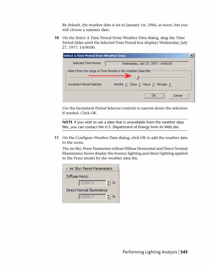
10 On the Select A Time Period From Weather Data dialog, drag the TimePeriod slider until the Selected Time Period box displays Wednesday, July27, 1977; 14:00:00.
Use the Increment Period Selector controls to narrow down the selectionif needed. Click OK.
NOTE If you wish to use a date that is unavailable from the weather datafiles, you can contact the U.S. Department of Energy from its Web site.
11 On the Configure Weather Data dialog, click OK to add the weather datato the scene.
The mr Sky: Perez Parameters rollout Diffuse Horizontal and Direct NormalIlluminance boxes display the bounce lighting and direct lighting appliedto the Perez model by the weather data file.
Performing Lighting Analysis | 545

NOTE Luminance values can change considerably between one data file andanother, depending on whether the readings were taken under clear or cloudyconditions. To obtain a more representative set of luminance values for yourmodel, it is a good idea to review weather data from several different datesat a given time of year, and choose the data file with the median luminancevalues.
Next, you will extract a range of weather data to see how the illuminancevalues change over a six-hour period of time, ranging from mid morningto mid afternoon.
Choose a range of weather data:
1 With the Daylight object selected, go to the Modify panel and inthe Daylight Parameters rollout > Position group, click Setup.
2 In the Use Weather Data group, choose Display Data As Animation.
3 For the Start value, click Change Time Period and in the Select A TimePeriod From Weather Data dialog, use the slider and spinner controls toset the date and time to Wednesday, July 27, 1977; 9:00:00, then clickOK.
4 Repeat the previous step for the End value and set the time to 15:00:00.
The Use Weather Data group indicates a total of seven frames created asa result of the selection range.
5 Click Match Timeline, then click OK.
The timeline updates to show seven frames.
546 | Chapter 5 Lighting Tutorials
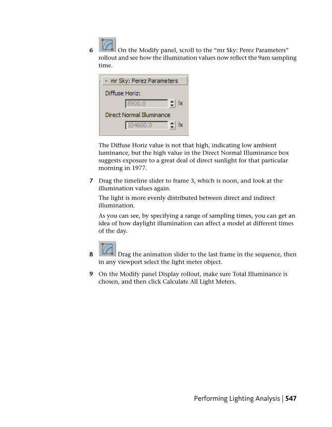
6 On the Modify panel, scroll to the “mr Sky: Perez Parameters”rollout and see how the illumination values now reflect the 9am samplingtime.
The Diffuse Horiz value is not that high, indicating low ambientluminance, but the high value in the Direct Normal Illuminance boxsuggests exposure to a great deal of direct sunlight for that particularmorning in 1977.
7 Drag the timeline slider to frame 3, which is noon, and look at theillumination values again.
The light is more evenly distributed between direct and indirectillumination.
As you can see, by specifying a range of sampling times, you can get anidea of how daylight illumination can affect a model at different timesof the day.
8 Drag the animation slider to the last frame in the sequence, thenin any viewport select the light meter object.
9 On the Modify panel Display rollout, make sure Total Illuminance ischosen, and then click Calculate All Light Meters.
Performing Lighting Analysis | 547

Light meter readings based on direct suinlight conditions
The level of illumination is much higher than that detected using theCIE Sky Model, even in the areas farthest from the windows. This isbecause the scene illumination is based not on an overcast day, but ona day of direct sunlight.
The Light Meter object uses color coding to help you visualize the lightingintensity in a scene. Lower intensities are displayed in cool colors suchas blue and green, while higher intensities are shown in orange and red.
The tennis court interior displays cool blue to the left, with even thelowest values in the acceptable illumination range, greater than 250 lux.To the right, by the windows, the color ramps up to pure white. Whiteareas indicate that the illumination values are outside the color-codingrange. You now need to adjust the color coding to obtain a more evengradient, so you can evaluate better the areas of high illumination.
Adjust lighting analysis color feedback:
1 From the main menu, choose Lighting Analysis > Lighting AnalysisAssistant, and go to the General panel.
The Analysis Value Color Coding rollout displays a color ramp. The rampintensity range is currently set between 0.0 and 10000.0 units. The unitsare in lux (lx), the international unit of measure. If you prefer, you can
548 | Chapter 5 Lighting Tutorials

switch to the American unit of measure, foot-candles (fc) on the UnitsSetup dialog.
Given the scene illumination is over 42,000 lux in places, the color rangeis currently too narrow. You therefore need to widen the color ramprange.
2 Change the value of the Max spinner to 45000.0, and press Enter.
In the viewport, the color range now shows light intensity much moreeffectively.
Light meter readings showing improved color coded feedback
Performing Lighting Analysis | 549

The orange areas of the tennis court interior show direct sunlight for thistime of day, while the blue areas show indirect sunlight.
3 From the > Scale drop-down list, choose Logarithmic.
The color-coded areas update to provide a different visualization of thelight intensity, but the intensity values themselves remain unchanged.
4 From the Scale list, choose Linear again.
5 Activate the Camera01 viewport, then press F9 to render the scene.
550 | Chapter 5 Lighting Tutorials

Computers with average processing capabilities will typically take fiveminutes or so to complete this task.
Rendered interior scene showing mid-afternoon illumination
The Perez All-Weather Sky model and weather data provide bright sceneillumination. Some image detail near the windows is washed out, but theinterior shows up in good detail.
NOTE The Perez model is suitable for daytime, but not for twilight or nightscenes. For scenes where the sun is low or absent, use the CIE model if youare concerned with photometric accuracy.
Exporting Light Meter Data and Rendering Light MeterData
In this lesson, you will learn how to export your Light Meter readings so thatothers can view them either in an Excel spreadsheet, or as a rendered imageoverlayed with light meter data.
Exporting Light Meter Data and Rendering Light Meter Data | 551
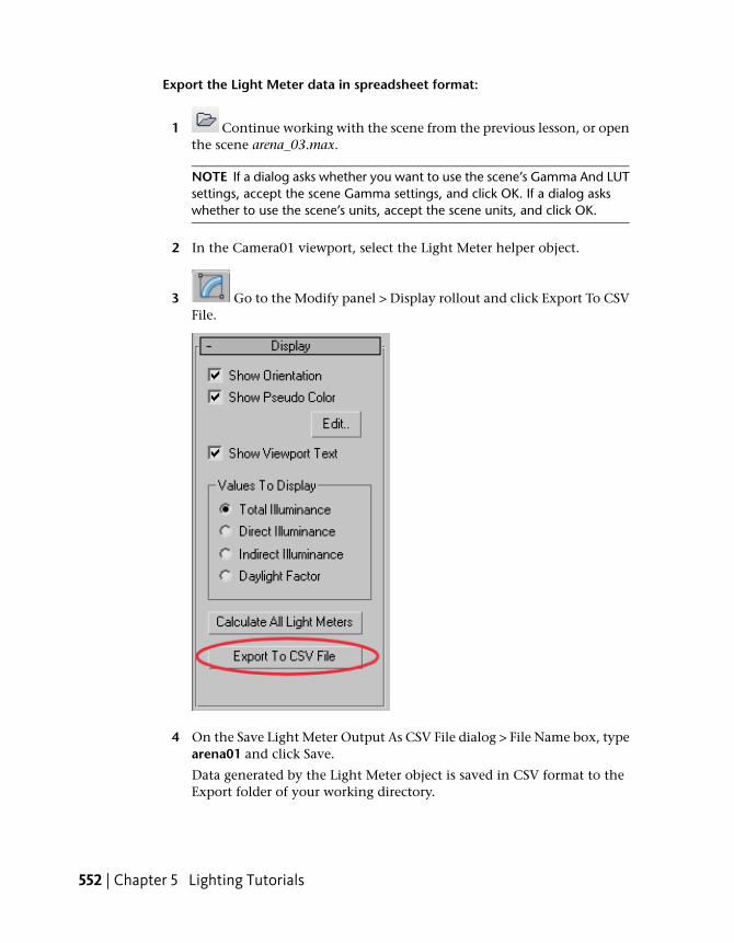
Export the Light Meter data in spreadsheet format:
1 Continue working with the scene from the previous lesson, or openthe scene arena_03.max.
NOTE If a dialog asks whether you want to use the scene’s Gamma And LUTsettings, accept the scene Gamma settings, and click OK. If a dialog askswhether to use the scene’s units, accept the scene units, and click OK.
2 In the Camera01 viewport, select the Light Meter helper object.
3 Go to the Modify panel > Display rollout and click Export To CSVFile.
4 On the Save Light Meter Output As CSV File dialog > File Name box, typearena01 and click Save.
Data generated by the Light Meter object is saved in CSV format to theExport folder of your working directory.
552 | Chapter 5 Lighting Tutorials

5 Navigate to your Export folder and open the newly saved file. Keep thefolder open for now.
The file opens in an Excel spreadsheet, showing light data gathered byeach point in the Light Meter helper. This data, formulated for technicalspecialists such as lighting engineers, is described in detail in the followingtable.
DefinitionColumn
Name of the Light Meter helper.A: Name
Number of the Light Meter helper sampling point.B: ID
Number of the frame in an animated sequence where thelight source was sampled. (A value of 0 indicates no anim-ation.)
c: Frame
Geographic location of the scene.D: Location
Time and date on which weather data used by the lightingsource was recorded.
E: Date
Value of direct illumination detected by the Light Metersampling point.
F: Direct
Value of indirect illumination detected by the Light Metersampling point.
G: Indirect
Exporting Light Meter Data and Rendering Light Meter Data | 553
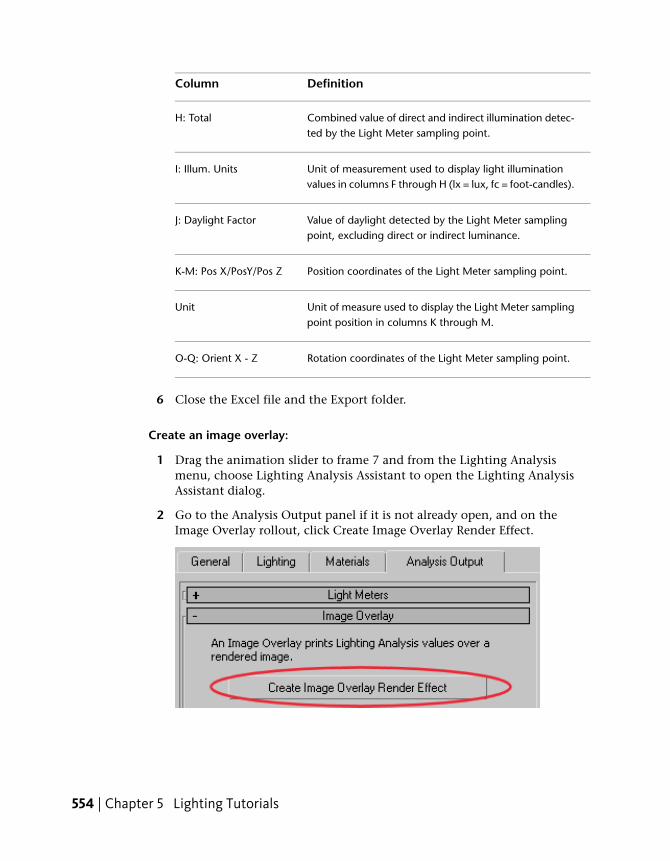
DefinitionColumn
Combined value of direct and indirect illumination detec-ted by the Light Meter sampling point.
H: Total
Unit of measurement used to display light illuminationvalues in columns F through H (lx = lux, fc = foot-candles).
I: Illum. Units
Value of daylight detected by the Light Meter samplingpoint, excluding direct or indirect luminance.
J: Daylight Factor
Position coordinates of the Light Meter sampling point.K-M: Pos X/PosY/Pos Z
Unit of measure used to display the Light Meter samplingpoint position in columns K through M.
Unit
Rotation coordinates of the Light Meter sampling point.O-Q: Orient X - Z
6 Close the Excel file and the Export folder.
Create an image overlay:
1 Drag the animation slider to frame 7 and from the Lighting Analysismenu, choose Lighting Analysis Assistant to open the Lighting AnalysisAssistant dialog.
2 Go to the Analysis Output panel if it is not already open, and on theImage Overlay rollout, click Create Image Overlay Render Effect.
554 | Chapter 5 Lighting Tutorials

3 On the Environment And Effects dialog > Effects panel > Effects rollout,click Lighting Analysis Image Overlay to highlight it, and then in theParameters rollout > Display Options group, make sure all the optionsare turned on. Keep the dialog open.
Exporting Light Meter Data and Rendering Light Meter Data | 555

4 In the Effects rollout > Preview group, turn on Interactive.
556 | Chapter 5 Lighting Tutorials

The scene starts to render.
As soon as the calculation is complete, two rendered frames display.
The first frame renders entirely in yellow. It is used to create the overlayimage but contains no usable information. Close this window.
The second rendered frame includes a layer of luminance data derivedfrom the lighting analysis. The numbers are dense and not easy to readbecause they include lighting values in a grid, as well as values generatedby the Light Meter sample points.
NOTE If your rendering displays luminance data in a grid only, render thescene a second time.
Overlay shows combination of grid and sample point light meter data
Exporting Light Meter Data and Rendering Light Meter Data | 557

5 Keep the rendered frame open for now.
Adjust the display of Light Meter data:
1 In the Environment And Effects dialog > Parameters rollout > DisplayOptions group, turn off Show Numbers On Entire Image (Screen Grid).
Now only the luminance values returned by the sampling points of theLight Meter you created for the court surface are displayed.
The rendering updates instantly after you make your choice because youturned on Interactive in the Effects rollout > Preview group.
Notice how the maximum luminance values display in the lower-rightcorner of the rendered frame.
558 | Chapter 5 Lighting Tutorials
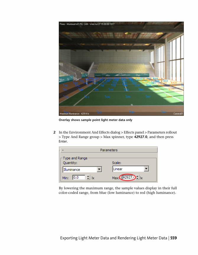
Overlay shows sample point light meter data only
2 In the Environment And Effects dialog > Effects panel > Parameters rollout> Type And Range group > Max spinner, type 42927.0, and then pressEnter.
By lowering the maximum range, the sample values display in their fullcolor-coded range, from blue (low luminance) to red (high luminance).
Exporting Light Meter Data and Rendering Light Meter Data | 559
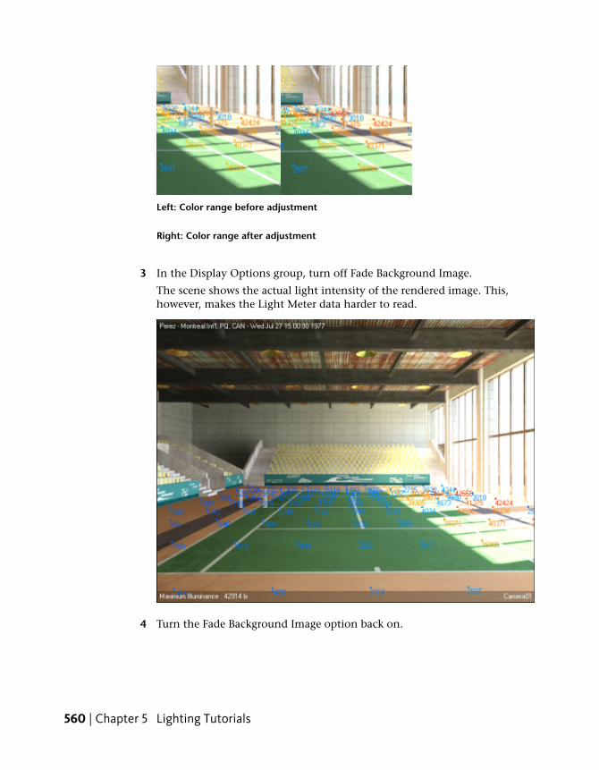
Left: Color range before adjustment
Right: Color range after adjustment
3 In the Display Options group, turn off Fade Background Image.
The scene shows the actual light intensity of the rendered image. This,however, makes the Light Meter data harder to read.
4 Turn the Fade Background Image option back on.
560 | Chapter 5 Lighting Tutorials

5 In the Display Options group, turn off Show Numbers From LightMetering Helper Objects and turn on Show Numbers On Entire Image.
The Light Meter luminance data is now sampled from 2D points on theimage surface. You can set the density of sampling points on the surfaceplane.
Overlay shows light meter data arranged in a 40 by 40 grid
6 In the Screen Grid Layout Options group, change the Vertical Spacingand Horizontal Spacing values to see how the overlay is affected.
7 In the Effects rollout > Preview group, click Show Original to view thescene without the lighting data. Click Show Effects to redisplay the data.
Exporting Light Meter Data and Rendering Light Meter Data | 561

8 On the Rendered Frame Window toolbar, click Save.
On the Save Image dialog, you can save the rendered image in a numberof formats to a location of your choosing.
9 If you like, you can view a completed version of this lesson by openingthe scene file arena_completed.max.
Summary
In this tutorial, you learned how to create a Daylight system and set theexposure to effectively illuminate an indoor scene. You then opened theLighting Analysis Assistant and prepared the scene for lighting analysis usinga helper object called a Light Meter, which evaluates the amount of direct andindirect illumination that enter a scene.
You also learned how to introduce realistic lighting conditions by downloadingweather data containing real-world meteorological observations, and applyingthese luminance values to your Daylight system. You then took the light meterreadings generated by the new luminance values, and converted them intospreadsheets and rendered overlays for subsequent analysis.
562 | Chapter 5 Lighting Tutorials