Tutorials - 15000 Inc.€¦ · Tutorials 5 1 NavisWorks Tutorials This tutorial is intended as an...
62
Tutorials NavisWorks 2
Transcript of Tutorials - 15000 Inc.€¦ · Tutorials 5 1 NavisWorks Tutorials This tutorial is intended as an...
Tutorials
NavisWorks 2

Copyright 2001 by NavisWorks LtdAll Rights ReservedNavisWorks Ltd. reserves the right to make changes in specification at any time and without notice. The information furnished by NavisWorks Ltd. in this publication is believed to be accurate; however, no responsibility is assumed for its use, nor for any infringement of patents or other rights of third parties resulting from its use.NavisWorks and the NavisWorks logo are registered trademarks of NavisWorks Ltd. Third party trademarksOpenGL is a trademark of Silicon Graphics, Inc.AutoCAD is a registered trademark of Autodesk, Inc.MicroStation is a registered trademark of Bentley Systems, Incorporated.SolidWorks is a registered trademark of SolidWorks Corporation.ArchiCAD is a registered trademark of Graphisoft.Windows and Windows NT are trademarks of Microsoft Corporation.Reproduction of any part of this document in any form whatsoever may only be undertaken with the written permission of NavisWorks Ltd.
NavisWorks Ltd.Rutledge House78 Clarkehouse RoadSheffieldS10 2LJUnited Kingdomemail: [email protected]
Acknowledgements:National Ice Centre model courtesy of Design & Property Services, Nottingham City Council, Nottingham, England.Scorpion TKX890 Snowmobile model courtesy of Scorpion Recreational Products, L.L.C. Manistee, Michigan, USA.City of Bath model courtesy of the Centre for Advanced Studies in Architecture, University of Bath, England.Gatehouse model courtesy of Dr. David Kerr, Taylor Woodrow, Taywood House, 345 Ruislip Road, Southall UB1 2QX, England.Eircom Park model courtesy of HBG Construction Ltd., Merit House, Colindale, London NW9 5AF, England. Architects: RHWL Partnership, 77 Endell St. London WCZH 9DZ, England. Client: IMG Ireland, 5 Clare St. Dublin 2 Ireland.KLM model courtesy of Laing Limited, Maxted House, 13 Maxted Rd., Hemel Hempstead HP2 7DX, England.
Tutorials
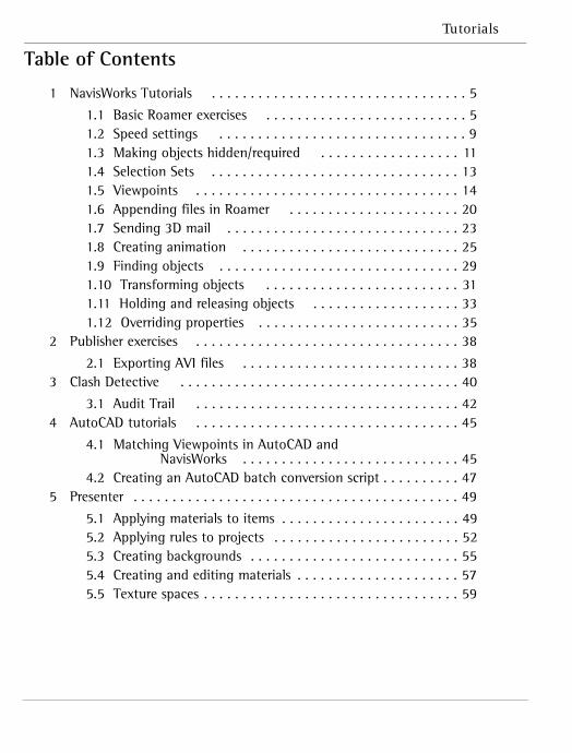
Table of Contents
1 NavisWorks Tutorials . . . . . . . . . . . . . . . . . . . . . . . . . . . . . . . . . 5
1.1 Basic Roamer exercises . . . . . . . . . . . . . . . . . . . . . . . . . . 51.2 Speed settings . . . . . . . . . . . . . . . . . . . . . . . . . . . . . . . . 91.3 Making objects hidden/required . . . . . . . . . . . . . . . . . . 111.4 Selection Sets . . . . . . . . . . . . . . . . . . . . . . . . . . . . . . . . 131.5 Viewpoints . . . . . . . . . . . . . . . . . . . . . . . . . . . . . . . . . . 141.6 Appending files in Roamer . . . . . . . . . . . . . . . . . . . . . . 201.7 Sending 3D mail . . . . . . . . . . . . . . . . . . . . . . . . . . . . . . 231.8 Creating animation . . . . . . . . . . . . . . . . . . . . . . . . . . . . 251.9 Finding objects . . . . . . . . . . . . . . . . . . . . . . . . . . . . . . . 291.10 Transforming objects . . . . . . . . . . . . . . . . . . . . . . . . . 311.11 Holding and releasing objects . . . . . . . . . . . . . . . . . . . 331.12 Overriding properties . . . . . . . . . . . . . . . . . . . . . . . . . . 35
2 Publisher exercises . . . . . . . . . . . . . . . . . . . . . . . . . . . . . . . . . . 38
2.1 Exporting AVI files . . . . . . . . . . . . . . . . . . . . . . . . . . . . 38 3 Clash Detective . . . . . . . . . . . . . . . . . . . . . . . . . . . . . . . . . . . . 40
3.1 Audit Trail . . . . . . . . . . . . . . . . . . . . . . . . . . . . . . . . . . 42 4 AutoCAD tutorials . . . . . . . . . . . . . . . . . . . . . . . . . . . . . . . . . . 45
4.1 Matching Viewpoints in AutoCAD and NavisWorks . . . . . . . . . . . . . . . . . . . . . . . . . . . . 45
4.2 Creating an AutoCAD batch conversion script . . . . . . . . . . 47 5 Presenter . . . . . . . . . . . . . . . . . . . . . . . . . . . . . . . . . . . . . . . . . . 49
5.1 Applying materials to items . . . . . . . . . . . . . . . . . . . . . . . 495.2 Applying rules to projects . . . . . . . . . . . . . . . . . . . . . . . . 525.3 Creating backgrounds . . . . . . . . . . . . . . . . . . . . . . . . . . . 555.4 Creating and editing materials . . . . . . . . . . . . . . . . . . . . . 575.5 Texture spaces . . . . . . . . . . . . . . . . . . . . . . . . . . . . . . . . . 59

NavisWorks
Tutorials
5
1 NavisWorks TutorialsThis tutorial is intended as an introduction to NavisWorks Roamer, Publisher and Clash Detective. The models it asks you to use are installed with NavisWorks in a subdirectory called “tutorials” which is installed on a “Full” installation. If you did another type of installation without the tutorials, then you can copy the directory off the NavisWorks CD onto your hard drive.
The first section is designed for Roamer users who wish to review models.
The second section is designed for the Publisher user who additionally wants to read file formats other than NavisWorks’ own formats (i.e. AutoCAD, 3DS, MicroStation). By working through the exercises below you will gain an understanding of how both Roamer and Publisher are used.
The third section is intended as an introduction to Clash Detective. By working through the exercises below you will gain an understanding of how Clash Detective is used and an appreciation of how it can manage and keep an audit of all your project’s clash testing.
The fourth section is designed for advanced users of AutoCAD who wish to automate batch processes and learn a procedure for speeding up the location of clashes.
This complete tutorial will take you approximately 2 hours to complete. Each exercise has been designed so that it can be worked through independently without having to complete previous exercises.
1.1 Basic Roamer exercises
This exercise has been designed to introduce you to moving around NavisWorks and using different methods of selecting objects. It should take between 5 and 10 minutes.
You will use the following control bars so ensure they are visible on your computer by checking the options in View, Control Bars.
NavisWorks
6
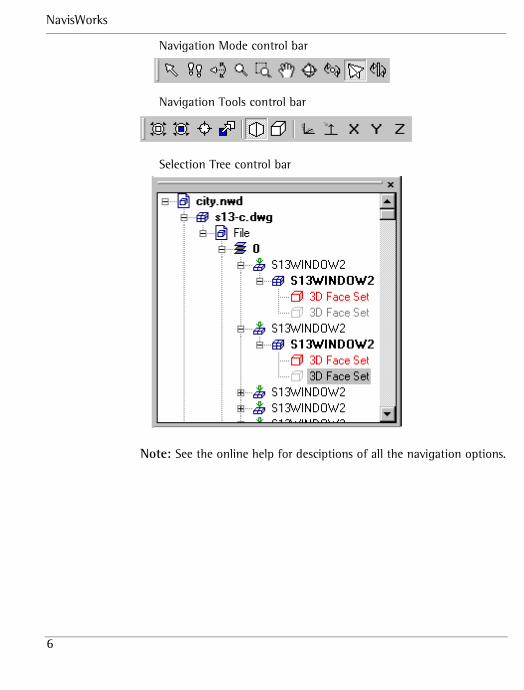
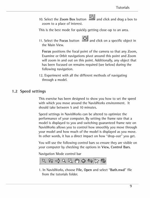
Navigation Mode control bar
Navigation Tools control bar
Selection Tree control bar
Note: See the online help for desciptions of all the navigation options.
Tutorials
7
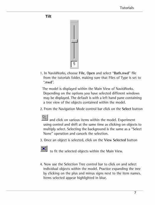
Tilt
1. In NavisWorks, choose File, Open and select “Bath.nwd” file from the tutorials folder, making sure that Files of Type is set to “.nwd”.
The model is displayed within the Main View of NavisWorks. Depending on the options you have selected different windows may be displayed. The default is with a left hand pane containing a tree view of the objects contained within the model.
2. From the Navigation Mode control bar click on the Select button
and click on various items within the model. Experiment using control and shift at the same time as clicking on objects to multiply select. Selecting the background is the same as a “Select None” operation and cancels the selection.
3. Once an object is selected, click on the View Selected button
to fit the selected objects within the Main View.
4. Now use the Selection Tree control bar to click on and select individual objects within the model. Practice expanding the tree by clicking on the plus and minus signs next to the item names.Items selected appear highlighted in blue.
NavisWorks
8
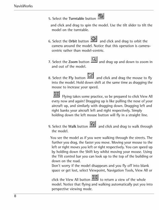
5. Select the Turntable button
and click and drag to spin the model. Use the tilt slider to tilt the model on the turntable.
6. Select the Orbit button and click and drag to orbit the camera around the model. Notice that this operation is camera-centric rather than model-centric.
7. Select the Zoom button and drag up and down to zoom in and out of the model.
8. Select the Fly button and click and drag the mouse to fly into the model. Hold down shift at the same time as dragging the mouse to increase your speed.
Flying takes some practice, so be prepared to click View All every now and again! Dragging up is like pulling the nose of your aircraft up, and similarly with dragging down. Dragging left and right banks your aircraft left and right respectively. Simply holding down the left mouse button will fly in a straight line.
9. Select the Walk button and click and drag to walk through the model.
You see the model as if you were walking through the streets. The further you drag, the faster you move. Moving your mouse to the left or right moves you left or right respectively. You can speed up by holding down the Shift key whilst moving your mouse. Using the Tilt control bar you can look up to the top of the building or down on the road.Don’t worry if the model disappears and you fly off into blank space or get lost, select Viewpoint, Navigation Tools, View All or
click the View All button to return a view of the whole model. Notice that flying and walking automatically put you into perspective viewing mode.
Tutorials
9
10. Select the Zoom Box button and click and drag a box to zoom to a place of interest.
This is the best mode for quickly getting close-up to an area.
11. Select the Focus button and click on a specific object in the Main View.
Focus positions the focal point of the camera so that any Zoom, Examine or Orbit navigations pivot around this point and Zoom will zoom in and out on this point. Additionally, any object that has been focused on remains required (see below) during the following navigation.
12. Experiment with all the different methods of navigating through a model.
1.2 Speed settings
This exercise has been designed to show you how to set the speed with which you move around the NavisWorks environment. It should take between 5 and 10 minutes.
Speed settings in NavisWorks can be altered to optimize the performance of your computer. By setting the frame rate that a model is displayed to you and switching guaranteed frame rate on NavisWorks allows you to control how smoothly you move through your model and how much of the model is displayed as you move. In other words, it has a direct impact on how “drop-out” you get.
You will use the following control bars so ensure they are visible on your computer by checking the options in View, Control Bars.
Navigation Mode control bar
1. In NavisWorks, choose File, Open and select “Bath.nwd” file from the tutorials folder.
NavisWorks
10
The model is displayed within the Main View of NavisWorks. Depending on the options you have selected different windows may be displayed. The default is with a left hand pane containing a tree view of the objects contained within the model.
2. Go to the Speed menu and ensure Guarantee Frame Rate is checked.
This option results in NavisWorks guaranteeing the frame rate you select for navigation around the model.
3. Go to Speed, Frame Rate and set the speed to 1 fps.
By setting the frame rate to 1 frame per second (fps) and having the guaranteed frame rate option NavisWorks guarantees that you can now navigate around the model at least 1 fps.
4. Navigate around the model using any of the buttons on the Navigation Mode control bar.
Notice how the picture seems to jump from frame to frame but the majority if not the whole model is displayed.
5. Now set the frame rate to 20 fps and navigate around the model.
Because the guaranteed frame rate is enabled, you can move through the model extremely smoothly however, unless you have a high-end graphics workstation, a lot of the model is “dropped out”.
6. Go to Speed and uncheck the Guarantee Frame Rate option.
7. Now navigate around the model using any of the buttons on the Navigation Mode control bar.
Because you have unchecked the Guarantee Frame Rate option NavisWorks renders everything in the model but your navigation interactivity is greatly reduced. If you have a high-end graphics workstation, this example model may be too small to notice any serious dropout, even at 20 fps. To make the point, try opening several of the north.nwd, south.nwd, east.nwd, west.nwd, central.nwd files in NavisWorks and roam around.
Tutorials
11
The NavisWorks default speed options are 6 fps and Guaranteed Frame Rate checked.
8. Set your speed options back to the default values.
1.3 Making objects hidden/required
This exercise has been designed to show you how to make objects in a model hidden or required in NavisWorks and the effect that this has on viewing. It should take between 5 and 10 minutes.
When you are reviewing a model in NavisWorks, you may wish to hide an object; for example, to remove the roof of a building to look inside. Conversely, an object may be important in a model and when roaming around the model you may always want to be able to see it; for example, some ductwork throughout a building. NavisWorks allows you to select objects and make them “hidden” or “required” and reset these objects back as necessary.
You will use the following control bars so ensure they are visible on your computer by checking the options in View, Control Bars.
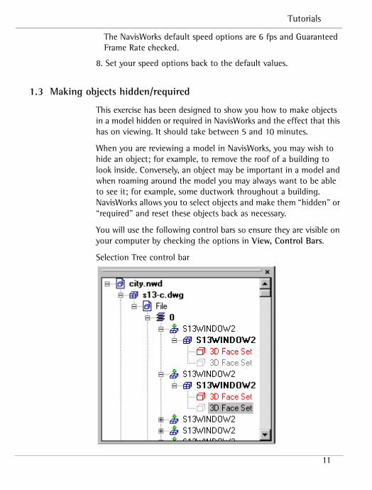
Selection Tree control bar
NavisWorks
12
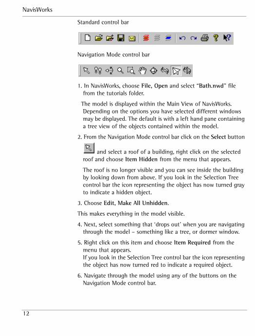
Standard control bar
Navigation Mode control bar
1. In NavisWorks, choose File, Open and select “Bath.nwd” file from the tutorials folder.
The model is displayed within the Main View of NavisWorks. Depending on the options you have selected different windows may be displayed. The default is with a left hand pane containing a tree view of the objects contained within the model.
2. From the Navigation Mode control bar click on the Select button
and select a roof of a building, right click on the selected roof and choose Item Hidden from the menu that appears.
The roof is no longer visible and you can see inside the building by looking down from above. If you look in the Selection Tree control bar the icon representing the object has now turned gray to indicate a hidden object.
3. Choose Edit, Make All Unhidden.
This makes everything in the model visible.
4. Next, select something that ‘drops out’ when you are navigating through the model – something like a tree, or dormer window.
5. Right click on this item and choose Item Required from the menu that appears.If you look in the Selection Tree control bar the icon representing the object has now turned red to indicate a required object.
6. Navigate through the model using any of the buttons on the Navigation Mode control bar.
Tutorials
13
You will notice that the item you selected and made Required is now always visible as you move about the model, whereas it wasn’t always before.
7. In the tree view, right click on the item you previously made Required and choose Item Required from the menu that appears.
By selecting the Item Required option again you undo the option and the object is no longer a required item. If you look in the Selection Tree control bar the icon representing the object has now returned to blue. Alternatively by right clicking on items,
you can select the item(s) and click on or in the Standard control bar for Required and Hidden respectively.
1.4 Selection Sets
This exercise introduces you to Selection Sets. It should take 2 to 5 minutes.
Selection sets allows you to store a selection. This may be useful if you wish to repeatedly switch between several groups of objects, or to hide/unhide a group of selected objects.
You will require the following control bars so ensure they are visible on your computer by checking the options in View, Control Bars, or by using the Workspace control bar.
Note: See the online help for descriptions of all the viewpoint options.
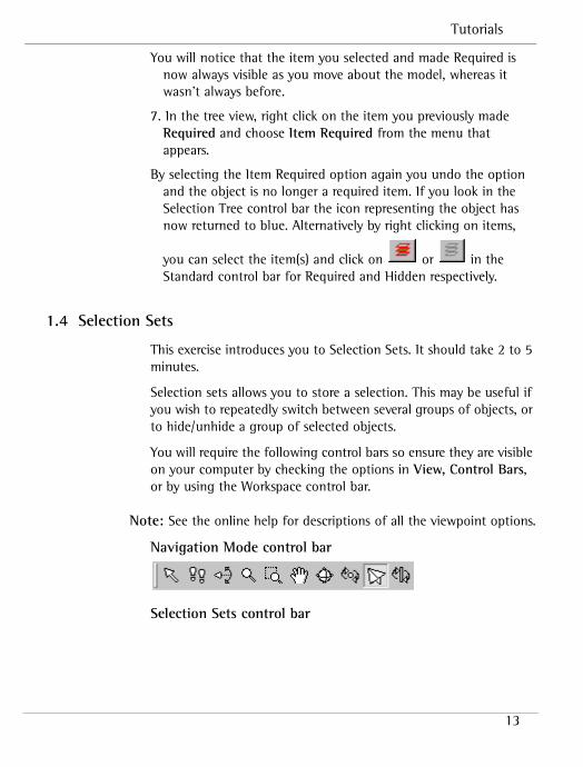
Navigation Mode control bar
Selection Sets control bar
NavisWorks
14
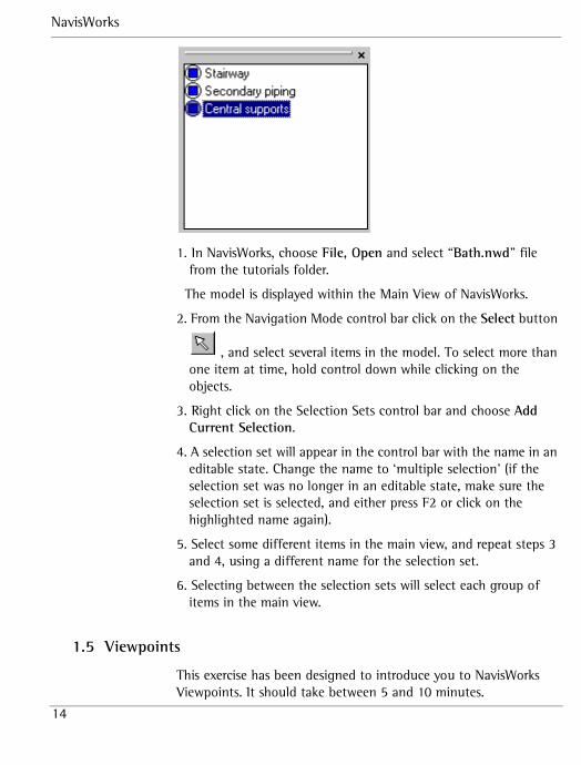
1. In NavisWorks, choose File, Open and select “Bath.nwd” file from the tutorials folder.
The model is displayed within the Main View of NavisWorks.
2. From the Navigation Mode control bar click on the Select button
, and select several items in the model. To select more than one item at time, hold control down while clicking on the objects.
3. Right click on the Selection Sets control bar and choose Add Current Selection.
4. A selection set will appear in the control bar with the name in an editable state. Change the name to ‘multiple selection’ (if the selection set was no longer in an editable state, make sure the selection set is selected, and either press F2 or click on the highlighted name again).
5. Select some different items in the main view, and repeat steps 3 and 4, using a different name for the selection set.
6. Selecting between the selection sets will select each group of items in the main view.
1.5 Viewpoints
This exercise has been designed to introduce you to NavisWorks Viewpoints. It should take between 5 and 10 minutes.
Tutorials
15
Viewpoints are an extremely useful feature of NavisWorks; they allow you to keep a record of all your “favorite” viewpoints in a model so that you can jump from view to preset view without having to navigate each time. You can record comments and red lining with each viewpoint in order to start discussing the design with the rest of your team (see 3D Mail later).
You will use the following control bars so ensure they are visible on your computer by checking the options in View, Control Bars, or by using the Workspace control bar.
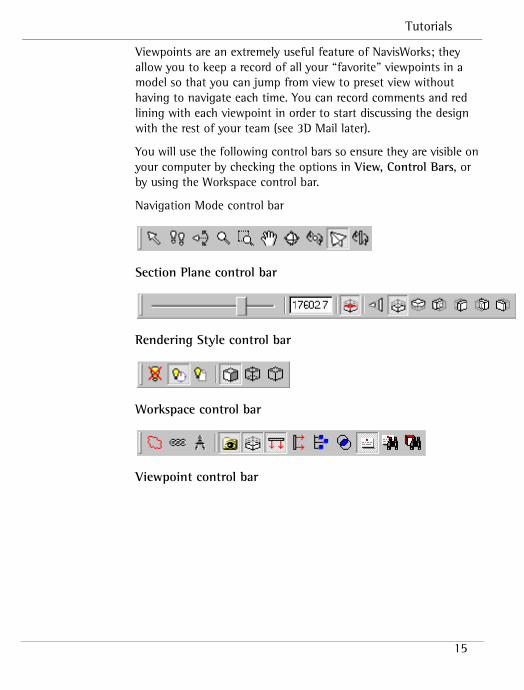
Navigation Mode control bar
Section Plane control bar
Rendering Style control bar
Workspace control bar
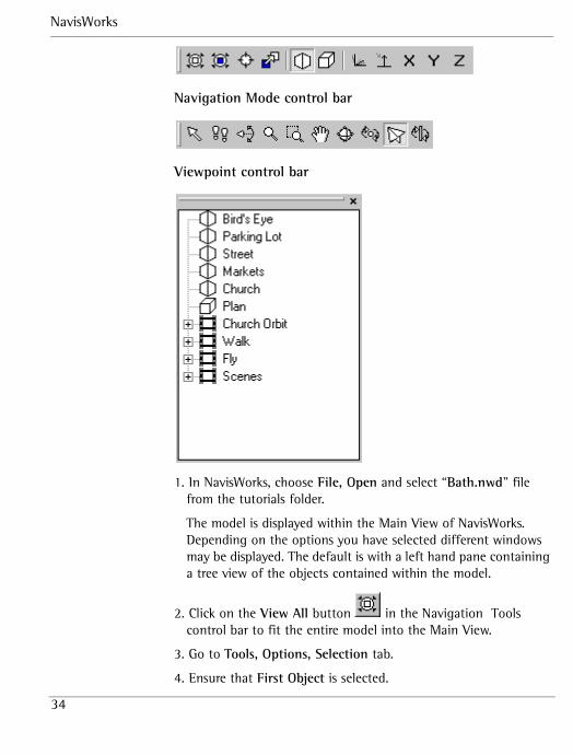
Viewpoint control bar
NavisWorks
16
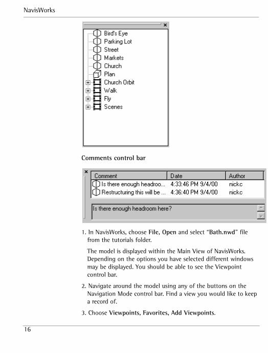
Comments control bar
1. In NavisWorks, choose File, Open and select “Bath.nwd” file from the tutorials folder.
The model is displayed within the Main View of NavisWorks. Depending on the options you have selected different windows may be displayed. You should be able to see the Viewpoint control bar.
2. Navigate around the model using any of the buttons on the Navigation Mode control bar. Find a view you would like to keep a record of.
3. Choose Viewpoints, Favorites, Add Viewpoints.
Tutorials
17
In the right hand pane (the Viewpoint control bar) ‘View1’ has been created.
4. Right click on ‘View1’ and select Edit to view its position details.
The Edit Viewpoint dialog box is displayed. This dialog box details all the information that NavisWorks stores in a saved viewpoint. Information that is contained includes the viewpoints camera position and both angular and linear speed of motion from the viewpoint. These speeds will determine how quickly you move through the model in the navigation modes.
5. Close the Edit Viewpoint dialog box, and again right click on ‘View1’, and this time select Add Comment. A text edit dialog box will appear – type some comments here and press OK.
6. The comments you have type appear in the Comments control bar. By right clicking in the upper box of the Comments control bar, you can add further comments.
7. Navigate away from your current position using any of the buttons on the Navigation Mode control bar.
8. Now in the Viewpoint control bar click on ‘View1’.
The saved viewpoint has restored the information of your previous camera position, what part of the model you where looking at (your focal point) and returned you to your original point.
9. Now in the Viewpoint control bar click on ‘View1’ again and change its name to ‘Bath1’ by pressing F2 or slow double clicking on the viewpoint name.
10. Go to Viewpoint, Look From, Top.
Now your model is viewed from above in plan form.
11. Go to Viewpoint, Look From, Front.
Now your model is viewed from the side.
12. Go to Viewpoint, Set World Up, -Z axis
Now your model appears upside down.
13. In the Viewpoint control bar select ‘Bath1’.
NavisWorks
18
14. Go to Viewpoint, Rendering, Wireframe
Now, instead of your model appearing with surfaces and shading, appears showing the triangles that constitute the model. You can
also click on the Rendering Style control bar.
15. Go to Viewpoint, Rendering, Shaded
Your model now appears with shading and surfaces. You could
also click on the Rendering Style control bar.
16. Go to Viewpoint, Lighting, No Lights.
By turning of the lights in the model the feeling of ‘depth’ is
turned off and surfaces look flatter. You could also click on the Rendering Style control bar.
17. Choose Viewpoints, Favorites, Add Viewpoints.
18. Follow the steps above to rename this viewpoint as ‘Bath 2’
19. Switch between the two views you have created
You can see how the combination of lighting, rendering and positioning can make a great difference to the way that your model appears.
20. Click the Enable/Disable button on the Section Plane control bar so that the other buttons on the control bar become enabled.
This toggle button allows the Section Plane control to be toggled on or off.
21. Click the Align Top button on the Section Plane control bar.
22. Now slowly drag the slider on the Section Plane Toolbar from right to left.
Tutorials
19
As you drag the slider further to the left more of the model appears, as if the buildings are been built from the ground up.
23.Finally, make another viewpoint and call it ‘section’.
24.Switch between the previous viewpoints you made and this viewpoint. Notice that the section plane sticks with the viewpoint. This enables you to animate a section being dragged through the model (see “creating animation” later).
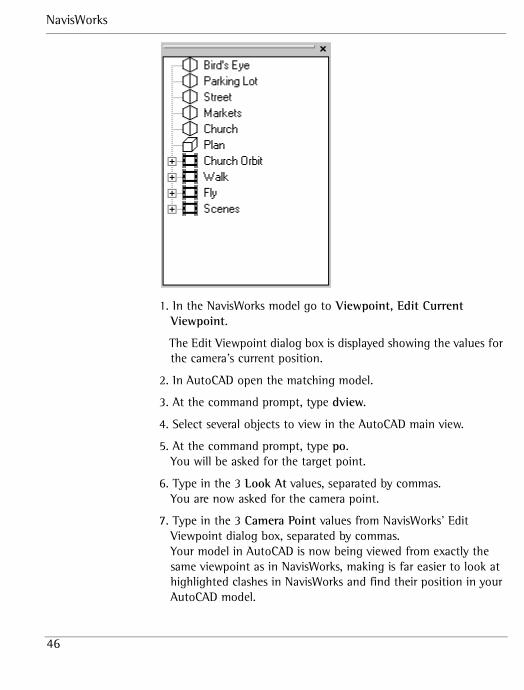
25. From the Viewpoints control bar select the view called ‘Church’.
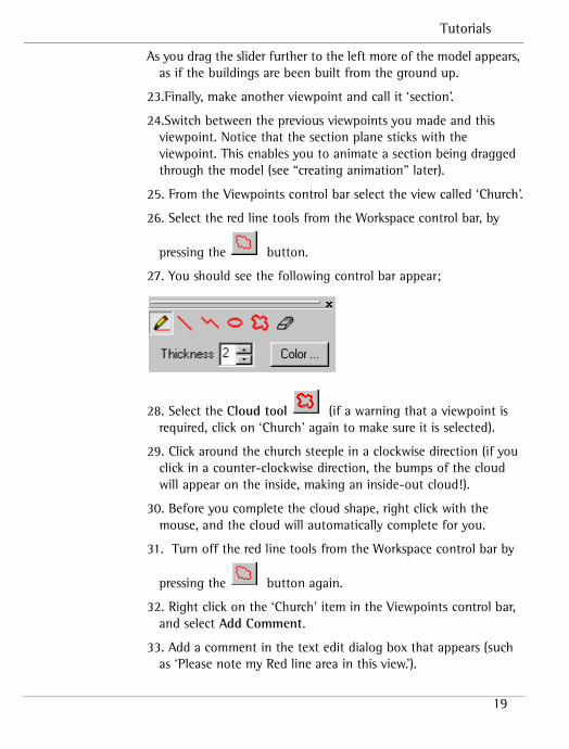
26. Select the red line tools from the Workspace control bar, by
pressing the button.
27. You should see the following control bar appear;
28. Select the Cloud tool (if a warning that a viewpoint is required, click on ‘Church’ again to make sure it is selected).
29. Click around the church steeple in a clockwise direction (if you click in a counter-clockwise direction, the bumps of the cloud will appear on the inside, making an inside-out cloud!).
30. Before you complete the cloud shape, right click with the mouse, and the cloud will automatically complete for you.
31. Turn off the red line tools from the Workspace control bar by
pressing the button again.
32. Right click on the ‘Church’ item in the Viewpoints control bar, and select Add Comment.
33. Add a comment in the text edit dialog box that appears (such as ‘Please note my Red line area in this view.’).
NavisWorks
20
34. Navigate away, or press on another saved view. If you return to ‘Church’ again, the cloud should also appear. Using Red lining and comments together is a powerful way of adding annotation to your views.
1.6 Appending files in Roamer
This exercise has been designed to show you how to append files in NavisWorks. It should take about 2 minutes.
NavisWorks allows you to add a model to the current set of models you are working on. With NavisWorks Roamer, you can only append *.nwd files, although in Publisher and above, you can append any of the supported file formats. The combined set of models may be saved as a single “published” NavisWorks file (*.nwd or *.nwf). *.nwd files save all the appended files as one single file, whereas *.nwf files save ‘pointers’ to the original files appended into a scene, along with your favorite viewpoints and comments.
You will use the following control bars so ensure they are visible on your computer by checking the options in View, Control Bars.
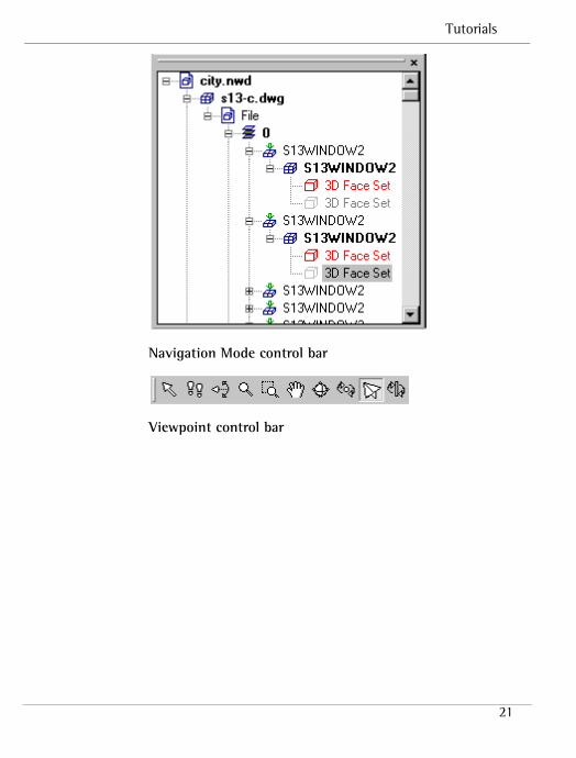
Selection Tree control bar
Tutorials
21
Navigation Mode control bar
Viewpoint control bar
NavisWorks
22
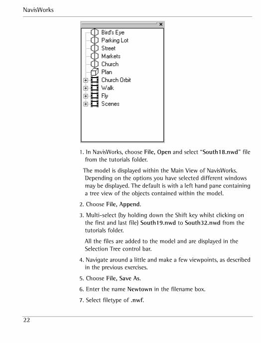
1. In NavisWorks, choose File, Open and select “South18.nwd” file from the tutorials folder.
The model is displayed within the Main View of NavisWorks. Depending on the options you have selected different windows may be displayed. The default is with a left hand pane containing a tree view of the objects contained within the model.
2. Choose File, Append.
3. Multi-select (by holding down the Shift key whilst clicking on the first and last file) South19.nwd to South32.nwd from the tutorials folder.
All the files are added to the model and are displayed in the Selection Tree control bar.
4. Navigate around a little and make a few viewpoints, as described in the previous exercises.
5. Choose File, Save As.
6. Enter the name Newtown in the filename box.
7. Select filetype of .nwf.
Tutorials
23
8. Choose Save.
An nwf file has now been created which points to the individual nwd files. The next time it is opened it will contain all the information stored within each .nwd file.
1.7 Sending 3D mail
This exercise has been designed to show you how NavisWorks allows you to communicate with other NavisWorks users via a MAPI compliant mail software. It should take between 5 and 10 minutes.
Note: In order to complete this exercise you must have a mail package installed on your machine. If you have not, clicking on the Send button will prompt you to connect to a mail exchange server.
You will use the following control bars so ensure they are visible on your computer by checking the options in View, Control Bars.
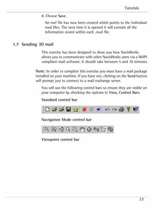
Standard control bar
Navigation Mode control bar
Viewpoint control bar
NavisWorks
24
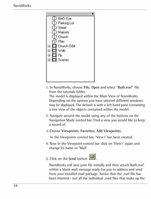
1. In NavisWorks, choose File, Open and select “Bath.nwf” file from the tutorials folder.The model is displayed within the Main View of NavisWorks. Depending on the options you have selected different windows may be displayed. The default is with a left hand pane containing a tree view of the objects contained within the model.
2. Navigate around the model using any of the buttons on the Navigation Mode control bar. Find a view you would like to keep a record of.
3. Choose Viewpoints, Favorites, Add Viewpoints.
In the Viewpoints control bar, ‘View1’ has been created.
4. Now in the Viewpoint control bar click on ‘View1’ again and change its name to ‘Mail’.
5. Click on the Send button .
NavisWorks will save your file initially and then attach Bath.nwf within a blank mail message ready for you to address and send from your installed mail package. Notice that the .nwf file has been inserted - not all the individual .nwd files that make up the

Tutorials
25
model. This results in the attachment been a much more manageable size.
Remember you can only send an .nwf file to someone who has access to the constituent *.nwd files, as an .nwf files contains ‘pointers’ to all the model information. If the recipient does not share a file server with you, then you can send the constituent *.nwd files separately and let them create the same file structure as yourself on their local machine. Saving the .nwf file from their mail (rather than double clicking to directly open NavisWorks) into the same location as you have will then allow them to open the same files.
6. Address the message to yourself.
7. Open the message when it is received in your Inbox.
8. In the message, double click on the attachment icon and choose “Open file from this location”.
The .nwf file is opened in NavisWorks and notice that the view ‘Mail’ along with any comments or red lining that you created have also been saved and sent. This enables communication about a design between the design team.
1.8 Creating animation
This exercise has been designed to show you how to animate your movement through NavisWorks. It should take between 10 and 15 minutes.
Animation allows you to share the model you’re working on with people who do not use NavisWorks. You can navigate around your model, add together different viewpoints and save as an animation which can then be played to others and if required exported as an .avi file (NavisWorks Publisher and above only) so that it can be played on their machine.
You will use the following control bars so ensure they are visible on your computer by checking the options in View, Control Bars.
NavisWorks
26
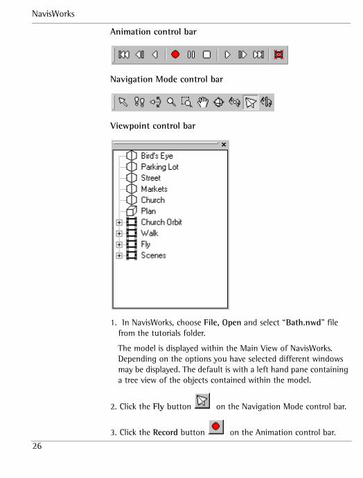
Animation control bar
Navigation Mode control bar
Viewpoint control bar
1. In NavisWorks, choose File, Open and select “Bath.nwd” file from the tutorials folder.
The model is displayed within the Main View of NavisWorks. Depending on the options you have selected different windows may be displayed. The default is with a left hand pane containing a tree view of the objects contained within the model.
2. Click the Fly button on the Navigation Mode control bar.
3. Click the Record button on the Animation control bar.
Tutorials
27
4. Fly around the model (for about 5 seconds).
5. Click the Stop button on the Animation control bar.
Your animation has been saved and if you were to close NavisWorks now it would still remain when the model was opened again. You can tell when you have an animation available
but not yet named by the appearance of the Erase button on the Animation control bar.
6. Right click on a blank area of the Viewpoint tree in the Viewpoint control bar and select Add Animation from the menu that appears.
An animation icon is displayed, ready for you to type a name.
7. Enter the name ‘Flying around’ and press Return.
8. In the Viewpoint tree in the Viewpoint control bar click on the + icon next to the animation you have just created.
Every frame contained within the animation you just recorded is displayed.
9. In the Viewpoint tree in the Viewpoint control bar click on the different frames within your newly record animation.
By clicking on a frame the view at that period of time is displayed.
10. Click on the Play button on the Animation control bar and watch your animation.
11. Try the other buttons on the Animation control bar to watch your animation in different ways for example, backwards.
12. Go to Viewpoints, Navigation Tools, View All.
The whole model is viewed from a distance.
NavisWorks
28
13. In the Viewpoint tree in the Viewpoint control bar right click on the last frame of your recorded animation and select Add Frame from the menu that appears. Rename it to “View All”.
A new view appears as the penultimate frame in the list.
14. In the Viewpoint tree in the Viewpoint control bar click and drag the last frame to the position above ‘View All’ so that ‘View All’ is the last frame.
15. Click the Play button on the Animation control bar to play the animation again and view the changes.
Notice that the animation has not simply jumped to the new frame ‘View All’ at the end of the animation but instead ‘smoothed out’ the large jump to the final frame.
16. In the Viewpoint tree in the Viewpoint control right click on the ‘Flying Around’ animation and choose edit.
17. Select Synchronize angular/linear speeds from the Smoothing pull down menu in the dialog box that appears.
18. Decrease the duration of the animation to about 5 seconds.
19. Choose OK.
20. Click the Play button on the Animation control bar to play the animation again and view the changes.
You should notice that unlike your actual recording (which was probably a bit erratic!), selecting this option has ‘smoothed out’ the animation so that the speed is more constant.
21. Now you will create an animation from a series of viewpoints. First, erase the current animation by clicking the Erase button
.
22. Then create a new blank animation by right clicking on the Viewpoint tree in the Viewpoint control bar and choosing Add Animation and call it ‘Street Roamer’.
Tutorials
29
23. Roam into the model to the end of a street and make a new viewpoint called ‘Anim1’.
24. Roam to the other end of the street and make another new viewpoint called ‘Anim2’.
25. Continue roaming around the streets, creating viewpoints to add to the animation.
26. Once all your viewpoints are created, holding down ctrl while left clicking on each one will allow you to select all of the viewpoints simultaneously.
27. Drag the viewpoints onto the ‘Street Roamer’ animation.
28. Now, right click on the ‘Street Roamer’ animation, select Edit and give the animation a suitable duration (say 10 seconds), and choose Synchronize angular/linear speeds from the Smoothing pull down menu.
29. If you play this animation now, you will see that NavisWorks interpolates between the viewpoints that you set up in order to create a smooth walkthrough.
1.9 Finding objects
This exercise has been designed to show you how NavisWorks can help you locate objects within your NavisWorks model. It should take between 10 and 15 minutes.
In large model locating a specific object can sometimes be time consuming. Also if you want to make a global change to objects with the same properties then using the Find tool allows you to be confident that you have every required object in the model selected.
You will use the following control bars so ensure they are visible on your computer by checking the options in View, Control Bars.
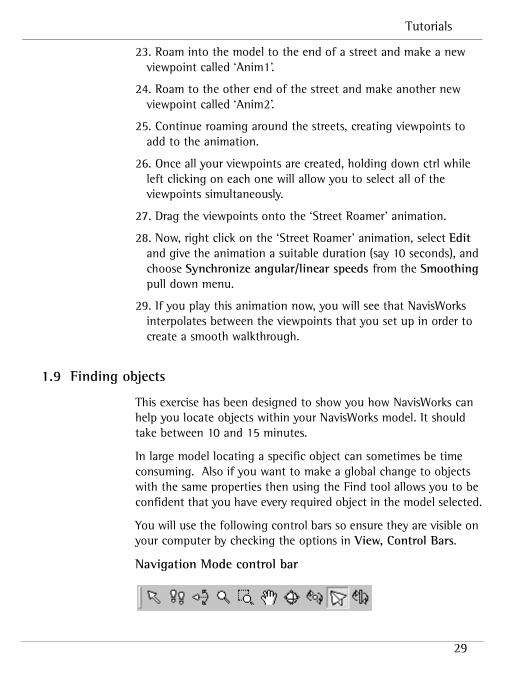
Navigation Mode control bar
NavisWorks
30
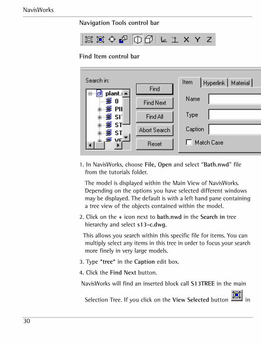
Navigation Tools control bar
Find Item control bar
1. In NavisWorks, choose File, Open and select “Bath.nwd” file from the tutorials folder.
The model is displayed within the Main View of NavisWorks. Depending on the options you have selected different windows may be displayed. The default is with a left hand pane containing a tree view of the objects contained within the model.
2. Click on the + icon next to bath.nwd in the Search in tree hierarchy and select s13-c.dwg.
This allows you search within this specific file for items. You can multiply select any items in this tree in order to focus your search more finely in very large models.
3. Type *tree* in the Caption edit box.
4. Click the Find Next button.
NavisWorks will find an inserted block call S13TREE in the main
Selection Tree. If you click on the View Selected button in
Tutorials
31
the Navigation Tools control bar, the Main View will zoom onto this tree.
5. Click the Find Next button again.
NavisWorks will find the block definition of this tree.
6. Type insert into the Type edit box and click the Find Next button once more.
On clicking Find Next now, NavisWorks will continue to find only those insertions of the S13TREE block, as the search is restricted to find only those items of type “insert” AND whose name has “tree” somewhere inside.
7. Clear the Type and Caption edit boxes and type S??tree into the Name edit box.
8. Choose bath.nwd in the Search in tree control.
9. Click the Find All button.
NavisWorks will find all the block definitions whose name begins with ‘S’, followed by 2 digits and ends in ‘tree’ and will select them in the main and tree views.Note: At any time in a long search, you can click the Abort Search button to stop searching. This might be useful in particularly large models.
10. Finally, clear the edit boxes of all text and click on the Material tab in the Find dialog box.
1.10 Transforming objects
This exercise has been designed to introduce you to transforming object properties within NavisWorks. It should take between 5 and 10 minutes.
NavisWorks allows you to transform an object’s properties. The main use for this feature is to allow you to resize an object when it is imported into NavisWorks at an incorrect scale. For example, if one .dwg file in a file set has been modeled in millimeters and
NavisWorks
32
everything else has been modeled in meters, the incoming .dwg will appear 1000 times too big.
You will use the following control bars so ensure they are visible on your computer by checking the options in View, Control Bars.
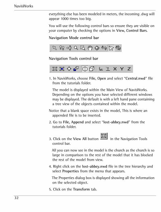
Navigation Mode control bar
Navigation Tools control bar
1. In NavisWorks, choose File, Open and select “Central.nwd” file from the tutorials folder.
The model is displayed within the Main View of NavisWorks. Depending on the options you have selected different windows may be displayed. The default is with a left hand pane containing a tree view of the objects contained within the model.
Notice that a blank space exists in the model, This is where an appended file is to be inserted.
2. Go to File, Append and select “lost-abbey.nwd” from the tutorials folder.
3. Click on the View All button in the Navigation Tools control bar.
All you can now see in the model is the church as the church is so large in comparison to the rest of the model that it has blocked the rest of the model from view.
4. Right click on the lost-abbey.nwd file in the tree hierarchy and select Properties from the menu that appears.
The Properties dialog box is displayed showing all the information on the selected object.
5. Click on the Transform tab.
Tutorials
33
6. Enter in the Scale fields 0.001, 0.001, 0.001.
By doing this you are scaling down the size of the church by a factor of 1000. You are transforming a model that used millimeters as its unit of measurement so that it is of the same proportions as the rest of the model whose unit of measurement is in meters. Now the church is the correct size and you can see the rest of the model. The church is still not quite in the right place, though, and doesn’t fit into its space in the model.
7. Click on the View All button in the Navigation Tools control bar and zoom into where the abbey should be.
8. Access the Transform tab again by right clicking on lost-abbey.nwd in the tree view and choosing Properties from the context menu.
9. Enter –10, -20, -30 in the Translation fields.
By doing this you are moving the church’s position –10 meter in the x-axis, -20 meters in the y-axis and –30 meters in the z-axis. Now the church should be the right size and located in the right place within the model.
1.11 Holding and releasing objects
This exercise has been designed to show you how to hold and release objects within a NavisWorks model. It should take between 5 and 10 minutes.
When you are reviewing a model it is often with the idea of seeing how a piece of machinery or building etc. will look when finished. NavisWorks not only allows you to review a model but actually lets you pick up objects from within a model and temporarily move then around and see how they will look in different positions in your model.
You will use the following control bars so ensure they are visible on your computer by checking the options in View, Control Bars.
Navigation Tools control bar
NavisWorks
34
Navigation Mode control bar
Viewpoint control bar
1. In NavisWorks, choose File, Open and select “Bath.nwd” file from the tutorials folder.
The model is displayed within the Main View of NavisWorks. Depending on the options you have selected different windows may be displayed. The default is with a left hand pane containing a tree view of the objects contained within the model.
2. Click on the View All button in the Navigation Tools control bar to fit the entire model into the Main View.
3. Go to Tools, Options, Selection tab.
4. Ensure that First Object is selected.
Tutorials
35
5. Choose OK.
6. Click the Select button from the Navigation Mode control bar and select one of the trees in the model.It is highlighted in blue.
7. If you click on the View Selected button in the Navigation Tools control bar, the Main View will zoom onto this tree.
8. Click on the Hold button in the Navigation Tools control bar to “pick up” the tree.
9. Now navigate around the model using the buttons on the Navigation Mode control bar.
You will notice that the tree is being moved as if you are holding out in front of you. This gives you the opportunity of looking at alternative locations for the tree.
10. Click on the Hold button in the Navigation Tools control bar to “put down” the tree.
The tree is released where it is currently positioned and you can now navigate around the model without the held object being moved.
11. Go to Edit, Reset, All Held Items.
The tree is placed back in its original position.
1.12 Overriding properties
This exercise has been designed to show how overriding properties can affect the way that models appear in NavisWorks. It should take between 5 and 10 minutes.
When you are working in a model in NavisWorks you may want to change some of the properties of objects, for example, changing the background of the model and setting transparency values of objects.
NavisWorks
36
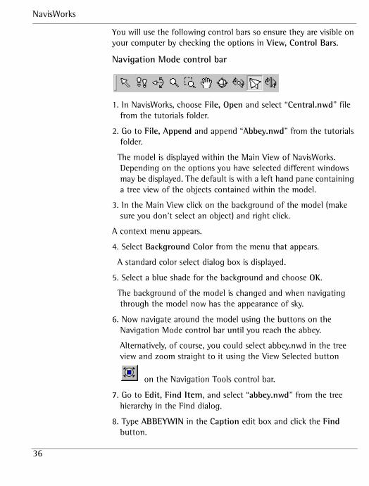
You will use the following control bars so ensure they are visible on your computer by checking the options in View, Control Bars.
Navigation Mode control bar
1. In NavisWorks, choose File, Open and select “Central.nwd” file from the tutorials folder.
2. Go to File, Append and append “Abbey.nwd” from the tutorials folder.
The model is displayed within the Main View of NavisWorks. Depending on the options you have selected different windows may be displayed. The default is with a left hand pane containing a tree view of the objects contained within the model.
3. In the Main View click on the background of the model (make sure you don’t select an object) and right click.
A context menu appears.
4. Select Background Color from the menu that appears.
A standard color select dialog box is displayed.
5. Select a blue shade for the background and choose OK.
The background of the model is changed and when navigating through the model now has the appearance of sky.
6. Now navigate around the model using the buttons on the Navigation Mode control bar until you reach the abbey.
Alternatively, of course, you could select abbey.nwd in the tree view and zoom straight to it using the View Selected button
on the Navigation Tools control bar.
7. Go to Edit, Find Item, and select “abbey.nwd” from the tree hierarchy in the Find dialog.
8. Type ABBEYWIN in the Caption edit box and click the Find button.
Tutorials
37
NavisWorks will find the first instance of a large gothic window in the abbey.
9. Zoom to this window by clicking on the View Selected button
on the Navigation Tools control bar.
10. Choose Edit, Override, Transparency.
11. Slide the slidebar to approximately 50% transparency.
12. Choose OK.
13. Choose Edit, Select, None to deselect everything in the model so you can see the changes to the window’s transparency.
14. Go and have a close look at the window you selected.
Instead of being blue and opaque you can now see through the window into the tower.
You should note that making a lot of objects transparent within a model can have an adverse affect on rendering
NavisWorks
38
2 Publisher exercisesThe next exercise within the tutorial demonstrate how Publisher can be used to export animation created in NavisWorks as an AVI file, which is then available to all interested parties.
2.1 Exporting AVI files
This exercise should take about 2 minutes.
As mentioned previously, NavisWorks allows you to create animation of your movements around your model together with viewpoints you have created. For colleagues who do not have NavisWorks, .avi creation lets you create animations, which can be viewed from their machine.
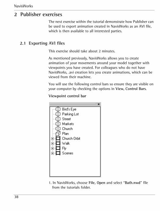
You will use the following control bars so ensure they are visible on your computer by checking the options in View, Control Bars.
Viewpoint control bar
1. In NavisWorks, choose File, Open and select “Bath.nwd” file from the tutorials folder.
Tutorials
39
The model is displayed within the Main View of NavisWorks. Depending on the options you have selected different windows may be displayed. The default is with a left hand pane containing a tree view of the objects contained within the model.
2. In the Viewpoint tree in the Viewpoint control bar click on ‘Fly’
3. Choose File, Export, Avi.The AVI Export dialog box is displayed with a default location and name for the AVI file highlighted.
4. Set the type to Explicit and set the size as 320 x 240.
5. Ensure the location of the AVI file is in the “tutorials” directory by typing in or clicking on Browse and selecting the location
6. Choose OK.
The conversion of the animation to an AVI file now takes place. The time that this takes depends on the anti-aliasing, size of the window and the size of the model. Note that no objects are ‘dropped’ from the avi file during animation.
7. Go to the tutorials directory and play the AVI file.
NavisWorks
40
3 Clash DetectiveThis tutorial is intended as an introduction to Clash Detective. By working through the exercises below you will gain an understanding of how Clash Detective is used and an appreciation of how it can manage and keep an audit of all your project’s clash testing.
1. Open “Clash.nwd” in NavisWorks and access the Clash Detective module by choosing Tools, Clash Detective.
2. Click on the Select tab and click on the PIPING_2 layer in the left tree view and the STEEL layer in the right tree view.
3. Change the Tolerance to 1 and click Start.
This sets up the clash test to clash these 2 layers against each other. Any intersection of 1 or greater will be flagged on the Results tab.
4. Click on the Result tab.
You should see in the top left hand pane of the tab one clash listed “Clash 1”. The main screen displays the clash that has been detected.
5. Rename the clash to “Bad Clash” by slow clicking on the name or by selecting it and pressing F2.
The new name will stay with the clash all the way through the project, so there is no need to repeat this each time you run a test.
View the clash on the main screen by experimenting with the Display Options on the right hand pane of the Results tab.
6. Try using Dim Other (turns all objects other than the clashing objects to gray), Hide Other (hides all non-clashing objects), and Auto Zoom (automatically focuses on the selected clash) in particular. Auto Reveal automatically hides any objects in the way of viewing a clash.
7. Go to Viewpoints, Favorites, Add Viewpoint to save a view of the clash you have found.
Tutorials
41
8. Click on the Batch tab, rename “Test1” to “piping_2_&_steel” .
Renaming the test enables you to easily identify the clash test at a later date.
9. Select File, Save As, and save the model as a NavisWorks file set (call it “my_clashes.nwf”).
10. Load “clash.dwg” in AutoCAD.
If you don’t have AutoCAD, just open “Clash2.nwd” into NavisWorks (this has the clashing object already moved) and save it as “Clash.nwd” (this will overwrite the original file. If you don’t want to do this, rename the original first). Renaming the files isn’t sufficient, since the new “Clash.nwd” must have a newer time stamp than the original. Go to step 12.
11. Move the clashing pipe so that it no longer clashes and export the model again to NavisWorks, overwriting the old clash.nwd model.
12. Load “my_clashes.nwf” into NavisWorks and open the Clash Detective again.
13. Click on the Batch tab.
Notice the status is old because NavisWorks has noticed that something has changed (in this case the model).
14. Click the Update button and click on the Results tab to view results.
The Update button has the same effect as clicking the Start button on the Select tab, only it goes through all currently loaded clash tests. We currently only have the one clash test in the batch (piping_2_&_steel), and so Update and Start are exactly the same in this situation.
Notice “Bad Clash” has now changed status to Resolved (indicated by yellow).
Also notice that NavisWorks still recognizes that this clash is the same as before (by calling it “Bad Clash” and changing its state to Resolved).
NavisWorks
42
3.1 Audit Trail
The next section within the tutorial demonstrates how Clash Detective can be used to keep a full audit trail of clashes identified within models, their status and how they were resolved.
1. Click on the Batch tab, click the Clear All button, and create a new test named “equipment_all”.
This will delete the existing clash test (piping_2_&_steel) and restore the clash defaults.
2. Click on the Select tab and go to main NavisWorks view.
We are going to select objects to clash against from the main NavisWorks view now, rather than via the tree view.
3. Go to the main screen menu and choose Tools, Options and ensure that Selection Options is set to Layer.
This allows us to pick an object and select the layer that it’s on.
4. Choose the Select button from the Navigation Modes control bar and click on one of the large green cylinders, so that the Equipment layer becomes selected.
5. In Clash Detective, click Current for Left object and select “Clash.nwd” (selecting everything) for Right object.
Current will select into the Clash Detective tree view whatever is selected in the main NavisWorks scene.
6. Set Tolerance to 0.1 and in Options tab, choose Clearance clash and check Objects on same layer.
Clearance clashes (or Soft clashes) are a superset of Hard clashes and essentially flag a clash if anything from the Right object comes within the tolerance limit of the Left object or vice versa. So here, anything from the whole model closer than 0.1mm (including negative clashes, which are all intersecting objects, or Hard clashes) to the Equipment layer will be flagged.
Checking Ignore Intersections Between Objects on same layer will do just that. Without this checked, you should get more clashes. For this test, we are not interested in finding these.
Tutorials
43
7. Click Start in Select tab.
You will get several clashes.
8. View the results that have been returned.
9. Set the Tolerance to 1 and re-start test.
10. View the results of the test.
You should now see more clashes, the previous set of which are of Active status and the rest New. Clearly, given a larger tolerance, more geometry is going to invade into other objects’ space and so more clashes are detected.
The Active status tells you that the Clash Detective has previously found the clashes and has found them again. They are, in effect, “Work in Progress”.
11. Create a new clash test and set up another test as shown before (valves_1 against equipment).
12. Click the Clean button and then the Update button.
Clean flushes out all previous knowledge of past tests and re-runs them from scratch. So any statuses you manually set, or clash names will be lost and it appears as though you had just set up this test for the first time. Compact, incidentally, cleans out all resolved clashes, in case your clash list is getting too huge to manage!
Update will now go through each clash test in turn and run them all again, one by one, just like a batch file that is going through each one, loading it, going to the Select page and clicking Start.
13. Then save this merged clash test as “All_January.nwf”.
14. Click on the Report tab and click preview to view an example report item.
15. Click Write Report to produce a report.
Report outputs an ASCII text file containing the clashes and tests you choose in the check boxes.
Selecting All Tests in the top right corner will output each clash for each test in the batch, Current Test will produce a report for
NavisWorks
44
each clash in the currently selected test, and Multiples Files will create a separate report for each test. The Include Clashes check boxes tell the report which clash statuses are required for this report. The check boxes in the Contents area select what information about each clash will be output in the report.
Tutorials
45
4 AutoCAD tutorialsThe exercises below are intended for advanced users of AutoCAD who want to increase the interaction between NavisWorks and AutoCAD. The first tutorial shows a method that enables you to locate clashes much more easily by matching your AutoCAD viewpoint to that of NavisWorks. The second tutorial shows you how to create an AutoCAD script to enable overnight processing of batch conversions to NavisWorks .nwd files.
4.1 Matching Viewpoints in AutoCAD and NavisWorks
This exercise has been designed to show you how to match viewpoints in AutoCAD and NavisWorks. It should take between 5 and 10 minutes.
When you are using Clash Detective in a complex model it is quite easy to see where clashes have been flagged as they are highlighted in the Main View. However, trying to find the same clashing objects in AutoCAD can be difficult. The exercise below shows you a simple method of matching your AutoCAD viewpoint with NavisWorks so that clashes are easier to spot.
You will use the following control bars so ensure they are visible on your computer by checking the options in View, Control Bars.
Viewpoint control bar
NavisWorks
46
1. In the NavisWorks model go to Viewpoint, Edit Current Viewpoint.
The Edit Viewpoint dialog box is displayed showing the values for the camera’s current position.
2. In AutoCAD open the matching model.
3. At the command prompt, type dview.
4. Select several objects to view in the AutoCAD main view.
5. At the command prompt, type po.You will be asked for the target point.
6. Type in the 3 Look At values, separated by commas.You are now asked for the camera point.
7. Type in the 3 Camera Point values from NavisWorks’ Edit Viewpoint dialog box, separated by commas.Your model in AutoCAD is now being viewed from exactly the same viewpoint as in NavisWorks, making is far easier to look at highlighted clashes in NavisWorks and find their position in your AutoCAD model.

Tutorials
47
8. At the command prompt type z if you want to zoom in to the model.
9. At the command prompt type d if you want to view the model in perspective view.
10. Press Enter to exit from the command prompt.
4.2 Creating an AutoCAD batch conversion script
This exercise has been designed to show you how to create batch conversion scripts. It should take about 10 minutes to set up the script.
You may have a very large model or a series of models that you wish to convert to NavisWorks files. This could take a long processing time and it is advantageous to process the conversion overnight. The method below shows how to create a script, which can be run overnight without intervention so that it is ready for you in the morning.
1. Open a text editor program, for example Notepad.
2. Type in your script. The example script below (which assumes that you have installed the tutorial files as indicated) set dialog boxes to off, opens “clash.dwg” and converts it to a NavisWorks file “clash.nwd”.
filedia 0open “C:\Program Files\NavisWorks Roamer\tutori-als\clash.dwg”nwdout C:\Program Files\NavisWorks Roamer\tutori-als\clash.nwdfiledia 1
Note: You should pay special attention to the filepath details for both the file to open and where the converted file is to be located. If you do not specify a path for the converted file it will locate the file in the default AutoCAD directory and overwrite any file of the same name. Additionally the script will not work if the directory specified does not exist.
NavisWorks
48
For AutoCAD 2000, it would be wise to make the first line of the script SDI 1 and the last line of the script SDI 0 so that you are not opening loads of files without closing them.
3. Save the script as “clash_test.scr”.
4. In AutoCAD type script
A dialog box appears for you to select your script.
5. Select this “clash_test” script. The script can now be left to run.
Tutorials
49
5 PresenterThis tutorial is intended to give an overview of the Presenter module’s functionality. By the end of this tutorial, you should be able to:
• Set up a palette of materials and apply them to objects in the scene;
• Set up project rules;
• Create backgrounds;
• Create new materials and edit their properties;
• Adjust texture spaces.
Throughout this tutorial, you will be using the Presenter dockable control, so if it is not already showing, click on the Tools, Presenter in the NavisWorks menu. It is recommended to dock this at the bottom of your NavisWorks window.
You will also use the Rendering Style control bar, so ensure it is visible within NavisWorks by checking its option in View, Control Bars.
Click on the Full Render button at any time to see the materials interactively.
5.1 Applying materials to items
This exercise demonstrates how to use the pre-defined archive of materials for the creation of a material palette, and how to apply materials from this palette to objects in the NavisWorks scene.
It should take about 10 to 15 minutes to complete.
NavisWorks
50
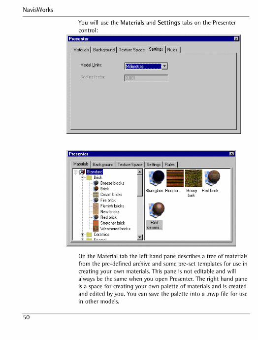
You will use the Materials and Settings tabs on the Presenter control:
On the Material tab the left hand pane describes a tree of materials from the pre-defined archive and some pre-set templates for use in creating your own materials. This pane is not editable and will always be the same when you open Presenter. The right hand pane is a space for creating your own palette of materials and is created and edited by you. You can save the palette into a .nwp file for use in other models.
Tutorials
51
1. In NavisWorks, choose File, Open and select “south10.nwd” from the tutorials folder. The model is displayed within the main view of NavisWorks.
2. Make sure that the selection behavior is set to “Layer” by going to Tools, Options, Selection and clicking the Layer radio button. NavisWorks Presenter uses the selection behavior to decide which items to apply the material to when dragging from the palette and onto the main view.
3. Change the model units to meters in the Settings tab.
4. In the left hand pane, open the brick materials folder by clicking on the ‘+’ to the left of “standard” and then on the ‘+’ to the left of “bricks”.
5. You should now see a list of different brick materials to use in your models. Drag the one called “Cream Bricks” onto the right hand pane. Once the material is in your palette, you can edit it for use it in the NavisWorks scene.
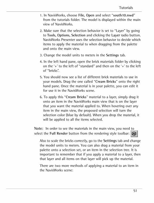
6. To apply this “Cream Bricks” material to a layer, simply drag it onto an item in the NavisWorks main view that is on the layer that you want the material applied to. When hovering over any item in the main view, the proposed selection will turn the selection color (blue by default). When you drop the material, it will be applied to all the items selected.
Note: In order to see the materials in the main view, you need to select the Full Render button from the rendering style toolbar:
Also to scale the bricks correctly, go to the Settings tab and change the model units to meters. You can also drag a material from your palette onto a selection set, or an item in the selection tree. It is important to remember that if you apply a material to a layer, then that layer and all items on that layer will pick up the material.
There are two more methods of applying a material to an item in the NavisWorks scene:
NavisWorks
52
• By selecting items from a combination of the selection tree and the main view, and then right clicking on this selection and selecting Presenter, Add material from the context menu.
• By right clicking on a material in the palette and select Apply to selected items from the context menu.
Take a few more materials out of the archive and into your palette and experiment with dragging them onto selection sets, the selection tree and items in the scene, with different selection behaviors. Notice that if you apply a material onto a more specific item (for example, some geometry on a layer), then that material will show on the item, overriding any material already on that layer.
Apply Azurelite glass from the Glass material folder to the windows and Mown grass from the Natural material folder to the grass in the courtyard.
You can remove materials from items in the scene by right-clicking on the item (whether in the selection tree or the main view) and selecting Presenter, Remove Material from the context menu. This option will only be available if there is a material actually applied to the item. If a material has been applied to a whole layer, and not explicitly to any objects on that layer, then right clicking on any items on the layer (with selection behavior set to “geometry”, for example), will not provide this “Remove Material” option, as there is no material on this specific item to remove.
To remove a material from all items in the scene, right click on the material in the palette and choose Remove from all items.
Once you’ve applied several different materials to the scene, make sure that “Cream bricks” is still in the palette for later exercises. Right click in a white space in the palette pane and choose Save Palette As and select a location to save this NavisWorks palette file as “My_Bath.nwp”. Overwrite the existing file if you like. This will be used later to apply to other models in the project.
Tutorials
53
5.2 Applying rules to projects
This exercise demonstrates how to apply a NavisWorks Palette (.nwp) file to other models in the same project that have been set up using the same layering or coloring conventions. It should take about 10 to 15 minutes to complete.
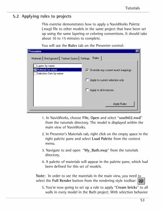
You will use the Rules tab on the Presenter control:
1. In NavisWorks, choose File, Open and select “south02.nwd” from the tutorials directory. The model is displayed within the main view of NavisWorks.
2. In Presenter’s Materials tab, right click on the empty space in the right palette pane and select Load Palette from the context menu.
3. Navigate to and open “My_Bath.nwp” from the tutorials directory.
4. A palette of materials will appear in the palette pane, which had been defined for this set of models.
Note: In order to see the materials in the main view, you need to select the Full Render button from the rendering style toolbar:
5. You’re now going to set up a rule to apply “Cream bricks” to all walls in every model in the Bath project. With selection behavior
NavisWorks
54
set to “Layer”, zoom in and right click on one of the beige walls in the scene, choose Properties from the context menu and click on the Material tab.
Make a note of the name of the material – “AutoCAD Color Index 41”. Drag your cursor over the text in the name box and copy it to the clip board with Ctrl-C.
6. Close this Properties dialog.
7. In the Materials tab of the Presenter control, if the “Cream bricks” material is not already in the palette, drag it there from the Bricks folder of the archive.
8. Select this material in the palette and press F2 to rename it. Paste the text from the clipboard by pressing Ctrl-V and press return. This should rename the material to that of the beige walls layer in the scene (AutoCAD Color Index 41).
9. Now click on the Rules tab in the Presenter control.
10. Set up the rules as shown in the dialog above – i.e. check “Materials by name” and uncheck “Apply to selected selection only”.
11.There are 3 pre-defined rules: “Materials by name”, “Layers by name”, and “Selection Sets by name”. Each of these works by applying a material with the same name as either the material, layer or selection set in the scene when the “Apply Rules” button is clicked. The options on the right describe how the rules are applied to items in the scene. Also, to scale the bricks correctly, go into the Settings tab and change the model units to meters.
12. Click the “Apply Rules” button to see the result of this rule. All the walls should now appear as cream bricks. If you had named any other materials in the palette in the same way, then all these material mappings would be applied at the time of application. For example drag “Azurelite glass” onto the palette and rename it “AutoCAD Color Index 131” and repeat steps 9 and 10 above.
13. You can save .nwp files in this way and simply re-apply the rules to all layers, materials and selection sets in the scene every time you update a model with new geometry, or add a model to
Tutorials
55
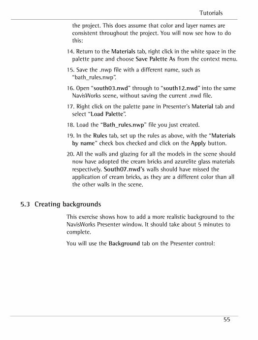
the project. This does assume that color and layer names are consistent throughout the project. You will now see how to do this:
14. Return to the Materials tab, right click in the white space in the palette pane and choose Save Palette As from the context menu.
15. Save the .nwp file with a different name, such as “bath_rules.nwp”.
16. Open “south03.nwd” through to “south12.nwd” into the same NavisWorks scene, without saving the current .nwd file.
17. Right click on the palette pane in Presenter’s Material tab and select “Load Palette”.
18. Load the “Bath_rules.nwp” file you just created.
19. In the Rules tab, set up the rules as above, with the “Materials by name” check box checked and click on the Apply button.
20. All the walls and glazing for all the models in the scene should now have adopted the cream bricks and azurelite glass materials respectively. South07.nwd’s walls should have missed the application of cream bricks, as they are a different color than all the other walls in the scene.
5.3 Creating backgrounds
This exercise shows how to add a more realistic background to the NavisWorks Presenter window. It should take about 5 minutes to complete.
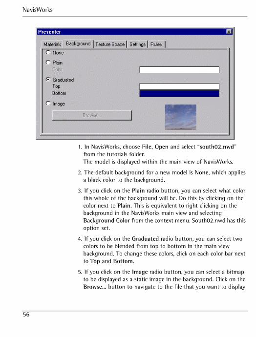
You will use the Background tab on the Presenter control:
NavisWorks
56
1. In NavisWorks, choose File, Open and select “south02.nwd” from the tutorials folder. The model is displayed within the main view of NavisWorks.
2. The default background for a new model is None, which applies a black color to the background.
3. If you click on the Plain radio button, you can select what color this whole of the background will be. Do this by clicking on the color next to Plain. This is equivalent to right clicking on the background in the NavisWorks main view and selecting Background Color from the context menu. South02.nwd has this option set.
4. If you click on the Graduated radio button, you can select two colors to be blended from top to bottom in the main view background. To change these colors, click on each color bar next to Top and Bottom.
5. If you click on the Image radio button, you can select a bitmap to be displayed as a static image in the background. Click on the Browse… button to navigate to the file that you want to display
Tutorials
57
in the background. Select the sky.bmp file in the tutorials directory.
5.4 Creating and editing materials
There are over 200 pre-defined materials in the archive. While these will meet many of your every day needs, they can never fulfil your every material requirement. To address this, there is also a group of templates for you to use to create and edit your own materials.
This exercise should take about 10 to 15 minutes to complete.
You will use the Settings and Materials tab on the Presenter control:
1. In NavisWorks, choose File, Open and select “south10.nwd” from the tutorials folder. The model is displayed within the main view of NavisWorks.
2. In the Settings tab, change the units to meters.
Note: Make sure that you have full render mode on by clicking the Full Render button on the rendering style toolbar:
4. Navigate to the “Red Brick” material in the Materials tab left hand pane by double clicking on standard and then double clicking on Brick.
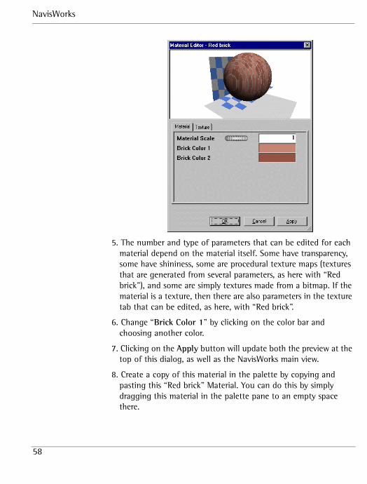
5. Double click on “Red Brick”. Notice that this automatically enters this material into your palette, so that it can be edited. The Material Editor dialog opens.
NavisWorks
58
5. The number and type of parameters that can be edited for each material depend on the material itself. Some have transparency, some have shininess, some are procedural texture maps (textures that are generated from several parameters, as here with “Red brick”), and some are simply textures made from a bitmap. If the material is a texture, then there are also parameters in the texture tab that can be edited, as here, with “Red brick”.
6. Change “Brick Color 1” by clicking on the color bar and choosing another color.
7. Clicking on the Apply button will update both the preview at the top of this dialog, as well as the NavisWorks main view.
8. Create a copy of this material in the palette by copying and pasting this “Red brick” Material. You can do this by simply dragging this material in the palette pane to an empty space there.
Tutorials
59
9. You should now have a material called “Red brick (2)”. Rename this to “brown brick” by selecting it and pressing F2 and typing in the new name.
10. Apply this material to the main walls of the model in the NavisWorks scene, ensuring that you have a selection behavior of by layer (chosen by going to Tools, Options, Selection)
11. Edit this new “brown brick” material by double clicking on it in the palette pane. Change Brick Color 1 to light brown and Brick Color 2 to dark brown and click on Apply. Notice how the material in the main view changes accordingly.
12. Click on the Texture tab in the Material editor dialog and play with some of the settings. Rotation rotates the brickwork and the scale and offset’s S and T values edit the scale and translation of the texture in two dimensions.
13. In the Settings tab, change the units to centimeters and notice how all the materials are scaled throughout the model accordingly. This setting can be used to apply a universal scale to all materials, based on the units that the model was originally created in. There is also a custom scaling factor, in case none of the standard units are applicable.
14. From the template materials folder, drag a glass material and an enamel material into the palette and experiment with editing their settings and applying them to the model. You can use these as starting materials to create your own from by renaming them and changing their properties. Save them for later use in an .nwp file.
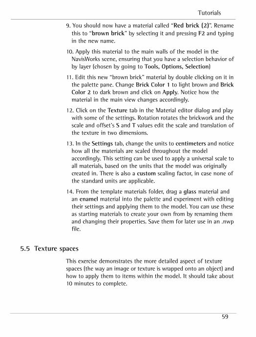
5.5 Texture spaces
This exercise demonstrates the more detailed aspect of texture spaces (the way an image or texture is wrapped onto an object) and how to apply them to items within the model. It should take about 10 minutes to complete.
NavisWorks
60
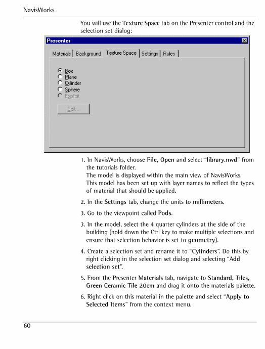
You will use the Texture Space tab on the Presenter control and the selection set dialog:
1. In NavisWorks, choose File, Open and select “library.nwd” from the tutorials folder. The model is displayed within the main view of NavisWorks.This model has been set up with layer names to reflect the types of material that should be applied.
2. In the Settings tab, change the units to millimeters.
3. Go to the viewpoint called Pods.
3. In the model, select the 4 quarter cylinders at the side of the building (hold down the Ctrl key to make multiple selections and ensure that selection behavior is set to geometry).
4. Create a selection set and rename it to “Cylinders”. Do this by right clicking in the selection set dialog and selecting “Add selection set”.
5. From the Presenter Materials tab, navigate to Standard, Tiles, Green Ceramic Tile 20cm and drag it onto the materials palette.
6. Right click on this material in the palette and select “Apply to Selected Items” from the context menu.
Tutorials
61
7. Zoom in to one of the cylinders and deselect everything (press Escape), which should now be tiled, assuming you have the Full Render button pressed on the Rendering Style toolbar.
8. Right click on the cylinder and select Presenter, Texture space, Cylinder. This should reveal a newly mapped tile pattern.
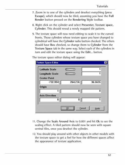
9. The texture space will now need editing to scale it to the curved fronts. Those cylinders whose texture space you have changed to cylindrical will have the Cylinder radio button checked. The others should have Box checked, so change them to Cylinder from the Texture Space tab in the same way. Select each of the cylinders in turn and edit the texture space using the Edit… button.
The texture space editor dialog will appear:
11. Change the Scale Around Axis to 0.001 and hit Ok to see the scaling effect. A tiled pattern should now be seen with square central tiles, once you deselect the cylinder.
12. You should play around with other objects in other models with the texture space to get a feel for how the different spaces affect the appearance of texture application.

NavisWorks
62