Tutorial: Molecular dynamics simulations for irradiation...
76
Tutorial: Molecular dynamics simulations for irradiation effects Kai Nordlund Professor, Department of Physics Adjoint Professor, Helsinki Institute of Physics Vice dean, Faculty of Science University of Helsinki, Finland
Transcript of Tutorial: Molecular dynamics simulations for irradiation...

Tutorial: Molecular dynamics simulations for irradiation effects
Kai Nordlund
Professor, Department of Physics
Adjoint Professor, Helsinki Institute of Physics
Vice dean, Faculty of Science
University of Helsinki, Finland

Kai Nordlund, Department of Physics, University of Helsinki 2
Greets from the white nights in Finland
[Picture by Kai Nordlund, midsummer 2012, Kukkia lake at midnight seen from Kuohijoki village]

Doc. Antti Kuronen Principal investigator
Doc. Jani Kotakoski Nanostructures
(TU Wien, Austria)
Prof. Kai Nordlund Principal investigator
M Sc Stefan Parviainen Particle physics mat'ls
Doc. Krister Henriksson Fusion reactor mat’s
M Sc Avaz Ruzibaev Particle physics mat’ls
M Sc Aleksi Leino Nanostructures in silica
M Sc Andrea Meinander Fusion reactor mat’ls
(maternity leave)
M Sc Ane Lasa Fusion reactor mat’ls
MSc Harriet Åhlgren Graphene
Dr Carolina Björkas Fusion reactor mat'ls
M Sc. Mohammad Ullah Irradiation of GaN
M Sc Kostya Avchachov Irradiation of metals
M Sc Andrey Ilinov Nanomechanics
M Sc Laura Bukonte Fusion reactor mat’ls
Dr Ville Jansson* Fusion reactor mat'ls
MSc Fredric Granberg Nanowires
Doc. Flyura Djurabekova* Principal investigator
M Sc Wei Ren Carbon nanostructures
MSc Morten Nagel Fusion reactor mat’ls
Dr Vahur Zadin* Particle physics materials
(also Univ. of Tartu)
Dr Bernhard Reischl Nanostructure metrology
M Sc Anders Korsbäck Particle physics materials
(CERN)
M Sc Junlei Zhao Nanoclusters
M´Sc Yi-Nan Liu Fusion reactor mat’ls
M Sc Elnaz Safi Fusion reactor mat’ls
The ion beam simulation groups in Helsinki

Kai Nordlund, Department of Physics, University of Helsinki 4
Contents
Background Irradiation effects in materials – brief summary of physics
The rich materials science emerging from ion irradiation
Molecular dynamics General approach
Features specific to ion irradiation and Irradiation effects
Some examples of recent applications from our group … of course many other groups also do excellent work …
Extra slides at end on Binary Collision Approximation and Kinetic Monte Carlo Slides available below my web home page, google for
“Kai Nordlund” and click on the “Tutorials…” link

Kai Nordlund, Department of Physics, University of Helsinki 5
Irradiation effects in materials
Background
~ 10 nm – 10 µm
Materials modification with
ion beams: ions from an
accelerator are shot into a
material
Huge (~ G€) business in
semiconductor industry!
Extensively studied since
1950’s or so.
Accelerator
5 – 300 mm
Dose 1010 – 1018 ions cm2
Flux 1010 – 1016 ions . cm2 s
Energy 10 eV – 1 GeV

Kai Nordlund, Department of Physics, University of Helsinki 6
Irradiation effects:
Basic physics
Schematical illustration of the ion slowing-down process
Log Energy
Log
σ slo
win
g
Collisions with electrons Collisions with electrons
Collisions with nuclei
Collisions with nuclei

Kai Nordlund, Department of Physics, University of Helsinki 7
Irradiation effects
Animation view from MD
A molecular dynamics (MD) simulation can make it much clearer what irradiation effects really looks like
Cross sectional view common
Ion
Material

Kai Nordlund, Department of Physics, University of Helsinki 8
Irradiation effects:
Animation view

Kai Nordlund, Department of Physics, University of Helsinki 9
Irradiation effects:
Ion beam and plasma energies and fluxes How do ions hit a material? From an accelerator, with a well-defined single energy E0
with very little energy spread Time between impacts ~ µs – s
on a nanometer scale =>
each impact independent
of each other
From a plasma more complex energy, wider energy spread, depends on kind of plasma If fluxes large, impacts can be close to each other in time
In an arc plasma, collision cascades can actually be
overlapping in place and time!
For neutrons, recoils deep inside the material, after that physics the same except no surface effects!

Kai Nordlund, Department of Physics, University of Helsinki 10
Irradiation effects:
What happens physically in the materials? Le
ngth
Time
ps ns μs ms s hours years
nm
μm
mm
m
Primary damage production (cascades)
Sputtering; Bubble formation; Point defect mobility
and recombination
Dislocation mobility and reactions
Swelling
Changes of macroscopic mechanical properties

Kai Nordlund, Department of Physics, University of Helsinki 11
Irradiation effects:
The rich materials science of irradiation effects
This is a demanding (and hence fun! ) range of materials physics issues to work on.
First stage: collision cascade by single incoming ion Simplified view:
[Wikipedia by Kai Nordlund]

Kai Nordlund, Department of Physics, University of Helsinki 12
Irradiation effects:
The rich materials science of Irradiation effects
But actually much more is going on. Just for a single ion all of the below may be produced:
Adatom Sputtered atom
Crater
Interstitial
Interstitial-like dislocation loop
Vacancy-like dislocation loop
3D extended defects
Implanted ion
Amorphization Vacancy

Kai Nordlund, Department of Physics, University of Helsinki 13
In addition, for multiple ions i.e. prolonged irradiation many more things can happen, for instance: Spontaneous roughening/ripple formation
Precipitate/nanocluster, bubble, void or blister formation inside solid
Irradiation effects:
The rich materials science of Irradiation effects: high fluences
[T. K. Chini, F. Okuyama, M. Tanemura, and K. Nordlund, Phys. Rev. B 67, 205403 (2003); Norris et al, Nature communications 2, 276 (2011)]
[Bubbles e.g: K. O. E. Henriksson, K. Nordlund, J. Keinonen, D, Physica Scripta T108, 95 (2004); Nanocrystals e.g. 75S. Dhara, Crit. Rev. Solid State Mater. Sci. 32, 1 [2007)]

Kai Nordlund, Department of Physics, University of Helsinki 14
Irradiation effects:
The rich materials science of Irradiation effects: high fluences
Phase changes, e.g. amorphization:
Spontaneous porousness formation, “fuzz” (e.g. in Ge, W)
Amorphous layer
Highly defective layer

Kai Nordlund, Department of Physics, University of Helsinki 15
BC
A
Irradiation effects:
What is needed to model all this? Le
ngth
Time
ps ns μs ms s hours years
nm
μm
mm
m
Classical Molecular dynamics
Kinetic Monte Carlo
Discrete dislocation dynamics
Finite Elements
Rate equations
DFT

Kai Nordlund, Department of Physics, University of Helsinki 16
Irradiation effects:
What is needed to model the atomic level?
One needs to be able to handle: 1) keV and MeV-energy collisions between nuclei
2) Energy loss to electronic excitations
3) Transition to high-pressure and high-T thermodynamics (Ekin ~
1 eV )
4) Realistic equilibrium interaction models
5) Phase changes, segregation, sputtering, defect production…
6) Long-term relaxation of defects
Sounds daunting, but: Steps 1 – 2 can be handled in a binary collision approximation
simulation Steps 1 – 5 can all be handled in the same molecular
dynamics simulation Step 6 requires kinetic Monte Carlo or rate theory

Kai Nordlund, Department of Physics, University of Helsinki 17
Contents
Background Irradiation effects in materials – brief summary of physics
The rich materials science emerging from ion irradiation
Molecular dynamics General approach
Features specific to ion irradiation and Irradiation effects
Some examples of recent applications from our group … of course many other groups also do excellent work …
Extra slides at end on Binary Collision Approximation and Kinetic Monte Carlo

Kai Nordlund, Department of Physics, University of Helsinki 18
MD method in equilibrium calculations
MD = Molecular dynamics
MD is solving the Newton’s (or Lagrange or Hamilton) equations of motion to find the motion of a group of atoms
Originally developed by Alder and Wainwright in 1957 to simulate atom vibrations in molecules Hence the name “molecular” Name unfortunate, as much of MD done nowadays does not
include molecules at all Already in 1960 used by Gibson to
simulate radiation effects in solids [Phys. Rev. 120 (1960) 1229)] A few hundred atoms, very
primitive pair potentials But found replacement collision
sequences!

Kai Nordlund, Department of Physics, University of Helsinki 19
MD method in equilibrium calculations
MD algorithm
Give atoms initial r(t=0) and v(0)
, choose short ∆t
Get forces F = − ∇ V(r(i)) or F = F(Ψ) and a = F/m
Move atoms: r(i+1) = r(i) +v(i)∆t + 1/2 a ∆t2 + correction terms Update velocities: v(i+1) = v(i) +a∆t + correction terms
Move time forward: t = t + ∆t
Repeat as long as you need

Kai Nordlund, Department of Physics, University of Helsinki 20
MD method in equilibrium calculations
MD – atom representations
MD naturally needs atom coordinates (and velocities) Atom coordinates can simply be read in from an ASCII
text file Simple but for atoms good enough format: .XYZ
Arrays in an MD code, e.g.: double precision :: x(MAXATOMS),y(MAXATOMS),z(MAXATOMS)

Kai Nordlund, Department of Physics, University of Helsinki 21
MD method in equilibrium calculations
MD – Solving equations of motion
The solution step r(i+1) = r(i) +v(i)∆t + 1/2 a ∆t2 + correction terms is crucial
What are the “correction steps”? There is any number of them, but the most used ones are
of the predictor-corrector type way to solve differential equations numerically:
Prediction: r(i+1),p = r(i) +v(i)∆t + 1/2 a ∆t2 + more accurate terms
Calculate F = − ∇ V(r(i)) and a = F/m
Calculate corrected r(i+1),c based on new a

Kai Nordlund, Department of Physics, University of Helsinki 22
MD method in equilibrium calculations
MD – Solving equations of motion
Simplest possible somewhat decent algorithm: velocity Verlet
Another, much more accurate: Gear5, Martyna
I recommend Gear5, Martyna-Tuckerman or other methods more accurate than Verlet – easier to check energy conservation
[C. W. Gear, Numerical initial value problems in ordinary differential equations, Prentice-Hall 1971; Martyna and Tuckerman J. Chem Phys. 102 (1995) 8071]
[L. Verlet, Phys. Rev. 159 (1967) 98]

Kai Nordlund, Department of Physics, University of Helsinki 23
MD method in equilibrium calculations
MD – time step selection Time step selection is a crucial part of MD
Choice of algorithm for solving equations of motion and time step
are related
Way too long time step: system completely unstable, “explodes” Too long time step: total energy in system not conserved Too short time step: waste of computer time
Pretty good rule of thumb: the fastest-moving atom in a system
should not be able to move more than 1/20 of the smallest
interatomic distance per time step – about 0.1 Å typically

Kai Nordlund, Department of Physics, University of Helsinki 24
MD method in equilibrium calculations
MD – Periodic boundary conditions
A real lattice can be extremely big E.g. 1 cm of Cu: 2.1x10²² atoms => too much even for
present-day computers Hence desirable to have MD cell as segment of bigger real
system Standard solution: periodic boundary conditions
This approach involves “copying” the simulation cell to each of the periodic directions (1–3) so that our initial system “sees” another system, exactly like itself, in each direction around it. So, we’ve created a virtual infinite crystal.

Kai Nordlund, Department of Physics, University of Helsinki 25
MD method in equilibrium calculations
MD: periodics continued
This has to also be accounted for in calculating distances for interactions
“Minimum image condition”: select the nearest neighbour of an atom considering all possible 27 nearest cells
Sounds tedious, but can in practice be implemented with a very simple comparison:

Kai Nordlund, Department of Physics, University of Helsinki 26
MD method in equilibrium calculations
MD – Boundary conditions
There are alternatives, though: Open boundaries = no boundary
condition, atoms can flee freely to vacuum Obviously for surfaces
Fixed boundaries: atoms fixed at boundary Unphysical, but sometimes needed for
preventing a cell from moving or making sure pressure waves are not reflected over a periodic boundary
Reflective boundaries: atoms reflected off boundary, “wall”
Combinations of these for different purposes

Kai Nordlund, Department of Physics, University of Helsinki 27
MD method in equilibrium calculations
MD – Temperature and pressure control
Controlling temperature and pressure is often a crucial part of MD
“Plain MD” without any T or P control is same as simulating NVE thermodynamic ensemble In irradiation simulations NVE only correct
approach to deal with the collisional phase !! NVT ensemble simulation: temperature is controlled
Many algorithms exist, Nosé, Berendsen, …
Berendsen simple yet often good enough
NPT ensemble simulation: both temperature and pressure is controlled Many algorithms exist: Andersen, Nosé-Hoover, Berendsen
Berendsen simple yet often good enough

Kai Nordlund, Department of Physics, University of Helsinki 28
MD method in equilibrium calculations
MD – cellular method and neighbour lists
To speed up MD for large (> 100 or so) numbers of atoms, a combination of neighbour list and a cellular method to find the neighbours is usually crucial
If one has N atoms, and want to find the neighbours for a finite-range potential, a direct search requires N2
operations – killing for large N Solution: if potential cutoff = rcut,
divide atoms into boxes of size >= rcut, search for neighbours only among the neighbouring cells
Neighbour list: form a list of neighbours within rcut+ rskin and update this only when needed

Kai Nordlund, Department of Physics, University of Helsinki 29
Nonequilibrium extensions – what else is needed to model nonequilibrium effects?
The basic MD algorithm is not suitable for high-energy interactions, and does not describe electronic stopping at all
But over the last ~25 years augmentations of MD to be able to handle this have been developed by us and others

Kai Nordlund, Department of Physics, University of Helsinki 30
What is needed to model irradiation effects?
1) keV and MeV-energy collisions between nuclei
To handle the high-E collisions, one needs to know the high-energy repulsive part of the interatomic potential We have developed DFT methods to obtain it to within
~1% accuracy for all energies above 10 eV
So called “Universal ZBL” potential accurate to ~5% and
very easy to implement
Simulating this gives the nuclear stopping explicitly!
Irradiation physics
Chemistry and materials science
[K. Nordlund, N. Runeberg, and D. Sundholm, Nucl. Instr. Meth. Phys. Res. B 132, 45 (1997)].

Kai Nordlund, Department of Physics, University of Helsinki 31
What is needed to model irradiation effects?
1) keV and MeV-energy collisions between nuclei
During the keV and MeV collisional phase, the atoms move with very high velocities Moreover, they collide strongly occasionally
To handle this, a normal equilibrium time step is not suitable
On the other hand, as ion slows down, time step can increase
Solution: adaptive time step

Kai Nordlund, Department of Physics, University of Helsinki 32
What is needed to model irradiation effects?
1) keV and MeV-energy collisions between nuclei
Adaptive time step example: Here ∆xmax is the maximum allowed distance moved during any t (e.g. 0.1 Å), ∆ Emax is the maximum allowed change in energy (e.g. 300 eV), vmax and Fmax are the highest speed and maximum force acting on any particle at t, respectively. c∆t prevents sudden large changes (e.g. 1.1), and tmax is the time step for the equilibrated system.
This relatively simple algorithm has been demonstrated to be able to handle collisions with energies up to 1 GeV accurately (by comparison with binary collision integral)
[K. Nordlund, Comput. Mater. Sci. 3, 448 (1995)].

Kai Nordlund, Department of Physics, University of Helsinki 33
What is needed to model irradiation effects?
2) Energy loss to electronic excitations
The energy loss to electronic excitations = electronic stopping S can be included as a frictional force in MD simply as: v(i+1) = v(i) – S(v)/m∆t
The nice thing about this is that this can be compared directly to experiments via BCA or MD range or ion transmission calculations. Examples of agreement:
[J. Sillanpää, K. Nordlund, and J. Keinonen, Phys. Rev. B 62, 3109 (2000); J. Sillanpää J. Peltola, K. Nordlund, J. Keinonen, and M. J. Puska, Phys. Rev. B 63, 134113 (2000); J. Peltola, K. Nordlund, and J. Keinonen, Nucl. Instr. Meth. Phys. Res. B 217, 25 (2003); J. Peltola, K. Nordlund, and J. Keinonen, Nucl. Instr. Meth. Phys. Res. B 212, 118 (2003)]
Log Energy
Log
σ slo
win
g
Electronic stopping power
Nuclear stopping

Kai Nordlund, Department of Physics, University of Helsinki 34
What is needed to model irradiation effects?
2) Energy loss to electronic excitations
The issue of how to deal with electronic stopping is thus well established at high E, but very recently it was realized that how the low-E limit is handled has a biggish (~ factor of 2) effect on damage production, and bigger on clustering
How should this be exactly treated? Electron-phonon coupling, weaker elstop (as shown by e.g. Arista et al), ??? Open issue to be solved – maybe ICACS community can help?
[Valdes et al, Nuclear Instruments and Methods B 193 (2002) 43; Pruneda et al, PRL 99, 235501 (2007]
Ele
ctr
on
ic d
ep
osi
ted
e
ne
rgy
in c
asc
ad
e [
keV
]
[A. E. Sand, S. L. Dudarev, and K. Nordlund,, EPL 103, 46003 (2013)]
150 keV W -> W

Kai Nordlund, Department of Physics, University of Helsinki 35
What is needed to model irradiation effects?
3) Transition to high-pressure and high-T thermodynamics
Requires realistic intermediate part in potential
Can be adjusted to experimental high-pressure data and
threshold displacement energies - Somewhat tedious ‘manual’ fitting but doable
Could also be fit to DFT database in this length range, although this rarely done
[K. Nordlund, L. Wei, Y. Zhong, and R. S. Averback, Phys. Rev. B (Rapid Comm.) 57, 13965 (1998); K. Nordlund, J. Wallenius, and L. Malerba. Instr. Meth. Phys. Res. B 246, 322 (2005); C. Björkas and K. Nordlund, Nucl. Instr. Meth. Phys. Res. B 259, 853 (2007); C. Björkas, K. Nordlund, and S. Dudarev, Nucl. Instr. Meth. Phys. Res. B 267, 3204 (2008)]

Kai Nordlund, Department of Physics, University of Helsinki 36
What is needed to model irradiation effects?
3) Transition to high-pressure and high-T thermodynamics
The transition to thermodynamics occurs naturally in MD
But boundary conditions a challenge due to heat and pressure wave emanating from a cascade

Kai Nordlund, Department of Physics, University of Helsinki 37
What is needed to model irradiation effects? 3) Transition to high-pressure and high-T thermodynamics: MD irradiation temperature control Central part has to be in NVE ensemble, but on the other
hand extra energy/pressure wave introduced by the ion or recoil needs to be dissipated somehow
Exact approach to take depends on physical question: a) surface, b) bulk recoil, c-d) swift heavy ion, e) nanocluster, f) nanowire
[A. V. Krasheninnikov and K. Nordlund, J. Appl. Phys. (Applied Physics Reviews) 107, 071301 (2010).

Kai Nordlund, Department of Physics, University of Helsinki 38
What is needed to model irradiation effects?
4) Realistic equilibrium interaction models
Finally one also needs the normal equilibrium part of the interaction model
Since we start out with the extremely non-equilibrium
collisional part, all chemical bonds in system can break and reform and atoms switch places Conventional Molecular Mechanics force fields are no good at all!
More on potentials in a few slides

Kai Nordlund, Department of Physics, University of Helsinki 39
What is needed to model irradiation effects?
5) Long-term relaxation of defects
The long-time-scale relaxation phase after the collisional stage can take microseconds, seconds, days or years Microseconds important in semiconductors Years important in nuclear fission and fusion reactor
materials
This is clearly beyond the scope of molecular dynamics Several groups have recently taken into use Kinetic Monte
Carlo (KMC) to be able to handle all this Also rate theory (numerical solution of differential
equations) can be extremely useful in this regard Outside the scope of this talk, but KMC slides added at
end [K. O. E. Henriksson, K. Nordlund, A. Krasheninnikov, and J. Keinonen, Appl. Phys. Lett. 87, 163113 (2005); K. O. E. Henriksson, K. Nordlund, A. Krasheninnikov, and J. Keinonen, Fusion Science & Technology 50, 43 (2006); [Ahl12] T. Ahlgren, K. Heinola, K. Vörtler, and J. Keinonen. J. Nucl. Mater., 427:152--161, 2012]

Kai Nordlund, Department of Physics, University of Helsinki 40
What is needed to model irradiation effects?
Whence the interactions?
Recall from the MD algorithm: This is the crucial physics input of the algorithm!
In the standard algorithm all else is numerical mathematics which can be handled in the standard cases to arbitrary accuracy with well-established methods (as outlined above)
Forces can be obtained from many levels of theory: Quantum mechanical: Density-Functional Theory (DFT),
Time-dependent Density Functional theory (TDDFT) - Limit: ~1000 atoms for DFT, ~100 atoms for TDDFT
Classically: various interatomic potentials - Limit: ~ 100 million atoms! - Most relevant to irradiation effects
Get forces F = − ∇ V(r(i)) or F = F(Ψ) and a = F/m

Kai Nordlund, Department of Physics, University of Helsinki 41
Interatomic potential development
Equilibrium potentials For classical MD the often only physical input is the potential Originally simple 2-body potentials, but by now these are almost
completely out of use except for noble gases Dominant are 3-body potentials, and increasingly 4-body are used Two major classes of potentials: Tersoff-like:
Embedded-atom method-like (EAM)
Both can be motivated in the second momentum approximation of tight binding (“extended Hückel approximation” if you are a chemist) Related to Pauling’s theory of chemical binding
repulsive attractiveneighbours
1( ) ( , , ) ( ) ;coordination of i ij ijk ij ik ijk ij ijkV V r b r r V r b
iθ = + ∝ ∑
repulsiveneighbours
( ) ( )i ij i ijj
V V r F rρ
= +
∑ ∑
[K. Albe, K. Nordlund, and R. S. Averback, Phys. Rev. B 65, 195124 (2002)]

Kai Nordlund, Department of Physics, University of Helsinki 42
Interatomic potential development
Potential development aims
First consider a potential for a pure element A. To be able to handle the effects described above, the
potential should give: The correct ground state: cohesive energy, crystal structure etc.
Describe all phases which may be relevant
Describe melting well
Describe defect energetics and structures well
If we further consider irradiation of a compound AB: For high-dose irradiation the compound may segregate, so
we need good models for elements A and B separately! Fulfills all the requirements just given for a pure element
Describes well the heat of mixing of the compound
Describes defects involving atom types A and B well

Kai Nordlund, Department of Physics, University of Helsinki 44
Interatomic potential development
Potential development approach
We start by obtaining information on as many coordination states as possible: Usually at least:
Z: 1 3 4 6 8 12
dimer graphite diamond SC BCC FCC
Data from experiments or DFT calculations
Cohesive energy, lattice constant, bulk modulus for all Z Elastic constants for most important
Fitting done in systematic approach introduced by Prof. Karsten Albe (TU Darmstadt)

Kai Nordlund, Department of Physics, University of Helsinki 45
Interatomic potential development
“Albe” fitting formalism
Use Tersoff potential in Brenner form (unique mathematical transformation)
The 3 parameters r0, D0 and β can be set directly from the
experimental dimer interatomic distance, energy and
vibration frequency!

Kai Nordlund, Department of Physics, University of Helsinki 46
Interatomic potential development
“Albe” fitting formalism
Key idea: In nn formulation,
if material follows
Pauling theory of
chemical bonding,
for all coordinations
Log
Ener
gy/b
ond
Bonding distance
DFT or expt. data dimer
GRA
DIA
SC BCC
FCC
[Albe, Nordlund and Averback, Phys. Rev. B 65 (2002) 195124]

Kai Nordlund, Department of Physics, University of Helsinki 47
Interatomic potential development
“Albe” fitting formalism
Pair-specific A-B interaction Three-body part modified from Tersoff form
This form for bij conforms exactly to
Second-moment approximation exponential
ik-dependent angular term
No power of 3
1coordination of ijkb
i∝
[Albe, Nordlund and Averback, Phys. Rev. B 65 (2002) 195124]

Kai Nordlund, Department of Physics, University of Helsinki 48
Interatomic potential development
The “blood, sweat and tears” part There are all in all 11 parameters that must be specified Constructing a good potential means finding suitable values
for these This is done by fitting to different experimental or density-
functional theory values of ground state and hypothetical
phases – also for other functional forms than Tersoff
Not a trivial task!
1-2 years
[Schematic courtesy of Dr. Carolina Björkas]

Kai Nordlund, Department of Physics, University of Helsinki 49
Interatomic potential development
Potentials developed in general In general, potentials suitable for irradiation effects exist:
For almost all pure elements
For the stoichiometric state of a wide range of ionic materials
- But these do not always treat the constituent elements sensibly,
e.g. in many oxide potentials O-O interactions purely repulsive =>
predicts O2 cannot exist => segregation cannot be modelled
For a big range of metal alloys
Not so many potentials for mixed metal – covalent compounds, e.g.
carbides, nitrides, oxides in non-ionic state
Extremely few charge transfer potentials
For organics only ReaxFF for CNOH, extended Brenner for COH
systems
NIST maintains a potential database, but pretty narrow coverage –
one often really needs to dig deep in literature to find them

Kai Nordlund, Department of Physics, University of Helsinki 50
Interatomic potential development
Potentials developed by us
We, and/or the Albe group, have so far developed potentials for: BN, PtC, GaAs, GaN, SiC, ZnO,
FePt, BeWCH, FeCrC, FeCH
+ He with pair potentials
All these potentials include all the
pure elements and combinations!
Fitting code “pontifix” freely
available, contact Paul Erhart
Just to give a flavor of complexity that can be modelled: prolonged irradiation of WC by H and He

Kai Nordlund, Department of Physics, University of Helsinki 51
Simulating swift heavy ion effects
Something new: swift heavy ions by MD
Swift heavy ions (i.e. MeV and GeV ions with electronic stopping power > 1 keV/nm) produce tracks in many insulating and semiconducting materials
Target
Energetic ion
[M. Lang et al, Earth and Planetary Science Letters 274 (2008) 355]

Kai Nordlund, Department of Physics, University of Helsinki 52
Simulating swift heavy ion effects
What happens physically: excitation models
The value of the electronic stopping is known pretty accurately
− Thanks to a large part to work in the ICACS community!
But even the basic mechanism of what causes the amorphization is
not known; at least three models are still subject to debate:
1. Heat spikes: electronic excitations translate quickly into lattice heating
that melts the lattice and forms the track
- “Two-temperature model”; Marcel Toulemonde, Dorothy Duffy, …
2. Coulomb explosion: high charge states make for an ionic explosion, high
displacements make for track
- Siegfried Klaumünzer, …
3. Cold melting: ionization changes interatomic potential into antibonding
one, repulsion breaks lattice and forms track
- Alexander Volkov, …

Kai Nordlund, Department of Physics, University of Helsinki 53
Simulating swift heavy ion effects
How to model it
Any of the models eventually translate into an interatomic movement, which can be handled by MD
Linking the electronic excitations stages can be implemented as a concurrent multiscale scheme
Get forces F = - ∇ V(r(n)) and a = F/m
Solve: r(n+1) = r(n) +v(n) Δt + 1/2 a Δt2 + … v(n+1) = v(n) + a Δt + …
Move time forward: t = t + Δ t; ; n=n+1
Repeat
Conventional MD Get modified interatomic potentials V*i(r(n),Se,t)
Solve: r(n+1) = r(n) +v(n) Δt + 1/2 a Δt2 + … v(n+1) = v(n) + a Δt + …
Move time forward: t = t + Δ t; n=n+1
Repeat
MD + antibonding or Coulomb
Get forces F = - ∇ V*i(r(n)) and a = F/m

Kai Nordlund, Department of Physics, University of Helsinki 54
Simulating swift heavy ion effects
How to model it
Any of the models eventually translate into an interatomic movement, which can be handled by MD
Linking the electronic excitations stages can be implemented as a concurrent multiscale scheme
Get forces F = - ∇ V(r(n)) and a = F/m
Solve: r(n+1) = r(n) +v(n) Δt + 1/2 a Δt2 + … v(n+1) = v(n) + a Δt + …
Move time forward: t = t + Δ t; ; n=n+1
Repeat
Conventional MD
Get forces F = - ∇ V*i(r(n)) and a = F/m
Solve: r(n+1) = r(n) +v(n) Δt + 1/2 a Δt2 + … v(n+1) = v(n) + a Δt + …
Move time forward: t = t + Δ t; n=n+1
Repeat
MD + heat spike model
Modify velocities: v(n+1) = v(n+1) + v*i(Se,t)

Kai Nordlund, Department of Physics, University of Helsinki 55
Simulating swift heavy ion effects
How to model it The concurrent multiscale models give a way to test the
excitation models against experiments We have implemented the heat-spike model and variations
of cold melting models into our MD code Basic result is that both heat-spike (Toulemonde) models
and cold melting models give tracks in SiO2
− Heat spike models give better agreement with experiments,
but the cold melting models cannot be ruled out – huge
uncertainties in how to modify potential

Kai Nordlund, Department of Physics, University of Helsinki 56
Simulating swift heavy ion effects
Sample result The two-temperature model in MD creates well-defined
tracks in quartz very similar to the experimental ones
[O. H. Pakarinen et al, Nucl. Instr. Meth. Phys. Res. B 268, 3163 (2010)]

Kai Nordlund, Department of Physics, University of Helsinki 57
Contents
Background Irradiation effects in materials – brief summary of physics
The rich materials science emerging from ion irradiation
Molecular dynamics General approach
Features specific to ion irradiation and Irradiation effects
Some examples of recent applications from our group … of course many other groups also do excellent work …
Extra slides at end on Binary Collision Approximation and Kinetic Monte Carlo

Kai Nordlund, Department of Physics, University of Helsinki 58
Examples of MD modelling results
1. Chemical sputtering of metals
58
Using classical molecular dynamics and experiments, we showed that pure metals can sputter chemically − Light metals under H bombardment sputter by breaking bonds!
[Björkas et al, New J. Phys. 11, 123017 (2009); Nordlund et al, NIM B 269, 1257 (2011)]

Kai Nordlund, Department of Physics, University of Helsinki 59
Examples of MD modelling results
2. Swift heavy ion effects on materials
Swift heavy ions (Ekin > 100 keV/amu) can be used to fabricate and modify nanostructures in materials
We are using multiscale modelling of electronic energy transfer into atom dynamics to determine the effects of swift heavy ions on materials
We have explained the
mechanism by which swift
heavy ions create
nanostructures in silicon, silica
and germanium and change
nanocrystal shapes
[Ridgway et al, Phys. Rev. Lett. 110, 245502 (2013); Leino et al, Mater. Res. Lett. (2013)]

Kai Nordlund, Department of Physics, University of Helsinki 60
Examples of MD modelling results
3. Surface nanostructuring
Together with Harvard University, we are examining the fundamental mechanisms of why prolonged ion irradiation of surfaces leads to formation of ripples (wave-like nanostructures)
[Norris et al, Nature commun. 2 (2011) 276]
We overturned the old paradigm that ripples are produced
by sputtering and showed ab initio that they can in fact be
produced by atom displacements in the sample alone

Kai Nordlund, Department of Physics, University of Helsinki 61
Examples of MD modelling results
4. Modelling of arc cratering
We have developed new concurrent multiscale modelling methods for treating very high electric fields at surfaces
Using it we are examining with a comprehensive multiscale model the onset of vacuum electric breakdown
[H. Timko et al, Phys. Rev. B 81 (2010), 184109]
We have shown that the complex crater shapes observed
in experiments can be explained as a plasma ion
irradiation effect – multiple overlapping heat spikes

Kai Nordlund, Department of Physics, University of Helsinki 62
Examples of MD modelling results
5. Cluster cratering over 40 orders of magnitude Using classical MD, we demonstrated that at a
size ~ 10000 atoms, cluster bombardment starts producing craters with the same mechanism as meteorites on planets − 100 million atom simulations with statistics
[J. Samela and K. Nordlund, Phys. Rev. Lett. 101 (2008) 27601, and cover of issue 2]

Kai Nordlund, Department of Physics, University of Helsinki 63
Summary
Molecular dynamics is a powerful tool for modelling irradiation effects – when you know what you are doing!
And a lot of fun!

www.helsinki.fi/yliopisto
Open positions: Experimental Tenure Track Professor
and Simulation postdoc and PhD student
The University of Helsinki, Department of Physics is soon opening a
Tenure track professor position in
Experimental materials (ion beam) physics (Applicant must be within 10 years of finishing PhD)
and groups of Kai Nordlund+Flyura Djurabekova now opening a
2+1.5 year postdoc on and 2+2 year PhD student position on simulation and theory of ripple formation
• Professorship, postdoc starting Jan 2015, PhD student September 2014 • Knowledge of Finnish not required!
64

Kai Nordlund, Department of Physics, University of Helsinki 65
Further reading
General: Classic book: Allen-Tildesley, Molecular dynamics
simulations of liquids, Oxford University Press, 1989. Newer book: Daan Frenkel and Berend Smit. Understanding
molecular simulation: from algoritms to applications.
Academic Press, San Diego, second edition, 2002
Ion irradiation-specific reviews: K. Nordlund and F. Djurabekova, Multiscale modelling of irradiation
in nanostructures, J. Comput. Electr. 13, 122 (2014). K. Nordlund, C. Björkas, T. Ahlgren, A. Lasa, and A. E. Sand,
Multiscale modelling of Irradiation effects in fusion reactor conditions, J. Phys. D: Appl. Phys. 47, 224018 (2014).
Tutorial material including these slides available below my web home page, google for “Kai Nordlund” and click on the “Tutorials…” link

Kai Nordlund, Department of Physics, University of Helsinki 66

Kai Nordlund, Department of Physics, University of Helsinki 67
Contents
Background Irradiation effects in materials – brief summary of physics
The rich materials science emerging from ion irradiation
Molecular dynamics General approach
Features specific to ion irradiation and Irradiation effects
Some examples of recent applications from our group … of course many other groups also do excellent work …
Extra slides at end on Binary Collision Approximation and Kinetic Monte Carlo
Kai Nordlund, Department of Physics, University of Helsinki 68
BCA method
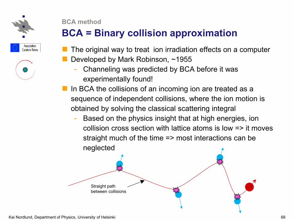
BCA = Binary collision approximation The original way to treat ion irradiation effects on a computer Developed by Mark Robinson, ~1955
- Channeling was predicted by BCA before it was experimentally found!
In BCA the collisions of an incoming ion are treated as a sequence of independent collisions, where the ion motion is obtained by solving the classical scattering integral - Based on the physics insight that at high energies, ion
collision cross section with lattice atoms is low => it moves straight much of the time => most interactions can be neglected
Straight path between collisions

Kai Nordlund, Department of Physics, University of Helsinki 69
BCA method
Illustration of BCA vs. MD
10 keV Ar -> Cu very thin foil (2 nm)
Molecular dynamics: as realistic as possible, all atom movements taken into account
Binary collision approximation (implemented within MD code)

Kai Nordlund, Department of Physics, University of Helsinki 70
BCA method
Illustration of BCA vs. MD
So was there a significant difference? In this particular case (5 – 1000 keV Ar -> Cu), yes:
Energy loss different even at 500 keV
Lower-energy recoils obviously missing from BCA
But this was single trajectories => in an average the difference certainly would have been much smaller!
[K. Nordlund, NIM B 266 (2008) 1886]

Kai Nordlund, Department of Physics, University of Helsinki 71
BCA method
Illustration of BCA vs. MD
Direct comparison by Gerhards Hobler&Betz [NIMB 180 (2001)
203] on the accuracy of MD vs. BCA in range and reflection: BCA ‘breakdown limit’ for non-channeling implantation into
Si at 5 % accuracy in the projected range is
30M10.55 eV
where M1 is the mass of the incoming ion [NIMB 180 (2001) 203]
- E.g. Si into Si: limit is 190 eV

Kai Nordlund, Department of Physics, University of Helsinki 72
BCA method
Different implementations
BCA can be implemented in many different ways BCA.1. “Plain” BCA : single collision at a time, static target BCA.2. Multiple-collision BCA: ion can collide with many
lattice atoms at the same time, static target - Needed at low energies
BCA.3. Full-cascade BCA: also all recoils are followed, static targets
BCA.4. “Dynamic” BCA: sample composition changes dynamically with implantation of incoming ions, ion beam mixing and sputtering
- full-cascade mode Usually ran with amorphous targets (“Monte Carlo” BCA)
but can also with some effort be implemented for crystals BCA is many many orders of magnitude more efficient
than MD

Kai Nordlund, Department of Physics, University of Helsinki 73
BCA method
BCA today and in the future?
Historically BCA was extremely important as full MD was too slow for most practical ion irradiation purposes
But now lots of things can be done with full MD or MD range calculations: BCA starts to get serious troubles in getting physics right below ~ 1 keV
What is the role of BCA now and in the future? It is still ideal method for quick calculations of ion depth profiles,
energy deposition, mixing, etc (BCA.1 and BCA.3) SRIM code important and very widely used
BCA with multiple collisions (BCA.2) is largely useless now
Dynamic BCA (BCA.4) is and will remain the best method for simulating very-high-fluence composition changes As long as chemistry and diffusion does not play a role!

Kai Nordlund, Department of Physics, University of Helsinki 74
Kinetic Monte Carlo
Kinetic Monte Carlo algorithm
1
i
i jj
R r=
= ∑Form a list of all N possible transitions i in the system with rates ri
Find a random number u1 in the interval [0,1] Carry out the event for which 1i N iR uR R− < <
Calculate the cumulative function for all i=0,…,N 0
i
i jj
R r=
= ∑
Move time forward: t = t – log u2/RN where u2 random in [0,1]
Figure out possible changes in ri and N , then repeat

Kai Nordlund, Department of Physics, University of Helsinki 75
Kinetic Monte Carlo
Comments on KMC algorithm
The KMC algorithm is actually exactly right for so called Poisson processes, i.e. processes occuring independent of each other at constant rates Stochastic but exact
Typical use: atom diffusion: rates are simply atom jumps But the big issue is how to know the input rates ri ??
The algorithm itself can’t do anything to predict them
I.e. they have to be known in advance somehow
From experiments, DFT simulations, … Also knowing reactions may be difficult Many varieties of KMC exist: object KMC, lattice object
KMC, lattice all-atom KMC, … For more info, see wikipedia page on KMC (written by me )

Kai Nordlund, Department of Physics, University of Helsinki 76
Kinetic Monte Carlo
Principles of object KMC for defects
Basic object is an impurity or intrinsic defect in lattice Non-defect lattice atoms are not described at all! Basic process is a diffusive jump, occurring at Arrhenius
rate
But also reactions are important: for example formation of divacancy from two monovacancies, or a pair of impurities
Reactions typically dealt with using a simple recombination radius: if species A and B are closer than some recombination radius rAB, they instantly combine to form defect complex
TkEi
BAerr /0
−=

Kai Nordlund, Department of Physics, University of Helsinki 77
Kinetic Monte Carlo
Example animation
Simple fusion-relevant example: He mobility and bubble formation in W Inputs: experimental He migration rate, experimental flux,
recombination radius of 3 Å, clusters assumed immobile
[K. O. E. Henriksson, K. Nordlund, A. Krasheninnikov, and J. Keinonen, Fusion Science & Technology 50, 43 (2006).]