Tutorial: How to draw SUV models with Astah...
40
Tutorial: How to draw SUV models with Astah SysML (Updated June 28, 2013) This tutorial is designed to help the readers to learn how to draw diagrams with Astah SysML using sample diagrams from the SysML specification by OMG. Throughout this tutorial, you will learn basic operations to draw diagrams with Astah. Table of Contents 1: Introduction - What is Astah SysML? 2: Let’s get started – installing and starting Astah SysML 3: Overview of Astah Window 4: Block Definition Diagram 5: Internal Block Diagram 6: Parametric Diagram 7: UseCase Diagram 8: Requirement Diagram 9: Thanks!
Transcript of Tutorial: How to draw SUV models with Astah...

Tutorial: How to draw SUV models with Astah SysML
(Updated June 28, 2013)
This tutorial is designed to help the readers to learn how to draw diagrams
with Astah SysML using sample diagrams from the SysML specification by
OMG. Throughout this tutorial, you will learn basic operations to draw
diagrams with Astah.
Table of Contents
1: Introduction - What is Astah SysML?
2: Let’s get started – installing and starting Astah SysML
3: Overview of Astah Window
4: Block Definition Diagram
5: Internal Block Diagram
6: Parametric Diagram
7: UseCase Diagram
8: Requirement Diagram
9: Thanks!
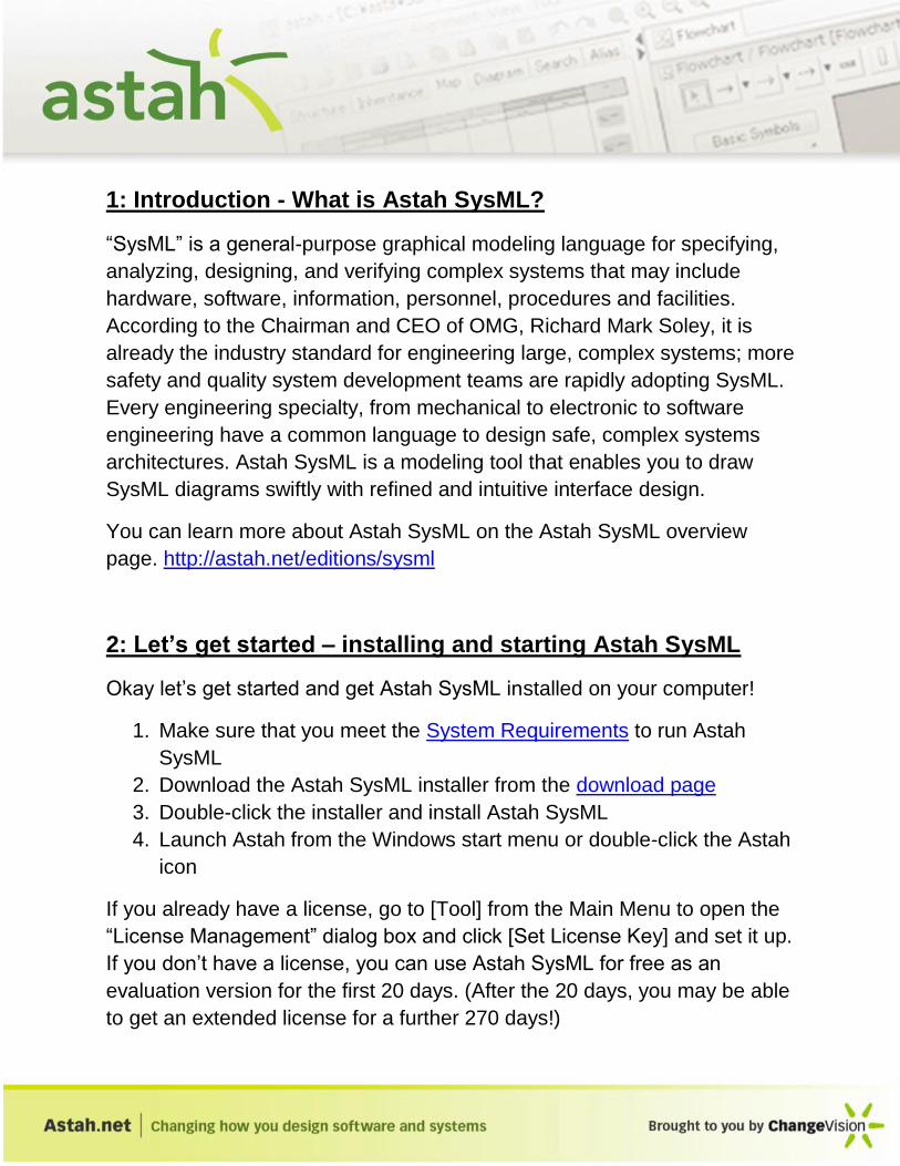
1: Introduction - What is Astah SysML?
“SysML” is a general-purpose graphical modeling language for specifying,
analyzing, designing, and verifying complex systems that may include
hardware, software, information, personnel, procedures and facilities.
According to the Chairman and CEO of OMG, Richard Mark Soley, it is
already the industry standard for engineering large, complex systems; more
safety and quality system development teams are rapidly adopting SysML.
Every engineering specialty, from mechanical to electronic to software
engineering have a common language to design safe, complex systems
architectures. Astah SysML is a modeling tool that enables you to draw
SysML diagrams swiftly with refined and intuitive interface design.
You can learn more about Astah SysML on the Astah SysML overview
page. http://astah.net/editions/sysml
2: Let’s get started – installing and starting Astah SysML
Okay let’s get started and get Astah SysML installed on your computer!
1. Make sure that you meet the System Requirements to run Astah
SysML
2. Download the Astah SysML installer from the download page
3. Double-click the installer and install Astah SysML
4. Launch Astah from the Windows start menu or double-click the Astah
icon
If you already have a license, go to [Tool] from the Main Menu to open the
“License Management” dialog box and click [Set License Key] and set it up.
If you don’t have a license, you can use Astah SysML for free as an
evaluation version for the first 20 days. (After the 20 days, you may be able
to get an extended license for a further 270 days!)

In this tutorial, we are going to show you how to draw the sample diagrams
from the SysML specification version 1.2 by OMG.
3: Overview of the Astah Window
Before we start, we should do a short overview of Astah – roles of each
pane, etc...
1: Management View
The Management View contains a menu bar and icons of frequently used
menu options.
2: Project View
The Project View consists the following five tabs:

Structure:
It shows all the diagrams and main models in
the tree so that you can see the model structure
in a tree view. You can also add new diagrams
or models from this section.
Inheritance:
This shows the inheritance tree of the models,
especially Blocks and Interfaces. Simply select a
model and see its inheritance(s) in the diagram.
You can add diagrams or models from this view
also.
Map:
You can control and adjust the area of diagram
to show in the diagram editor with this view. This
view is very useful when you have a large
diagram, you can select certain areas you want
to see enlarged in blue rectangle, and then
Astah shows the covered area in the diagram
editor.
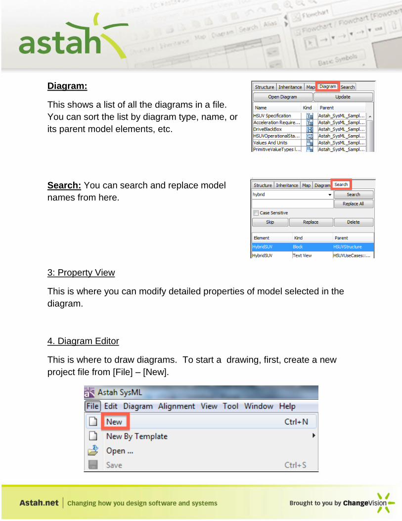
Diagram:
This shows a list of all the diagrams in a file.
You can sort the list by diagram type, name, or
its parent model elements, etc.
Search: You can search and replace model
names from here.
3: Property View
This is where you can modify detailed properties of model selected in the
diagram.
4. Diagram Editor
This is where to draw diagrams. To start a drawing, first, create a new
project file from [File] – [New].
4: Block Definition Diagram
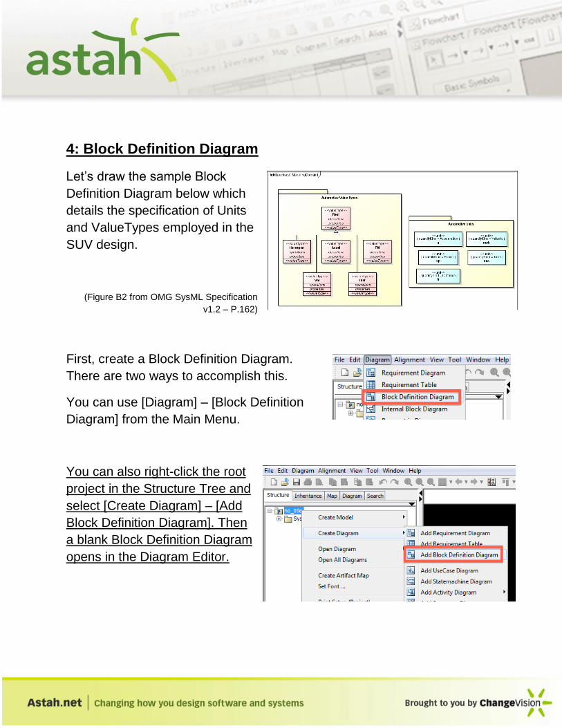
Let’s draw the sample Block
Definition Diagram below which
details the specification of Units
and ValueTypes employed in the
SUV design.
(Figure B2 from OMG SysML Specification
v1.2 – P.162)
First, create a Block Definition Diagram.
There are two ways to accomplish this.
You can use [Diagram] – [Block Definition
Diagram] from the Main Menu.
You can also right-click the root
project in the Structure Tree and
select [Create Diagram] – [Add
Block Definition Diagram]. Then
a blank Block Definition Diagram
opens in the Diagram Editor.

On the top of the Diagram Editor, there is a list of icons called “tool bar” that
has a menu to create models with.
To find out which icon does what, move your mouse over each icon, it will
tell you what the icon is for in a tool tip.
First, create the [Automotive Value Types] package. To create a Package,
select [Package] in the tool bar and then click the diagram.
A package will be added in the diagram, name it “Automotive Value Types”
and then hit the Enter key to complete.
Now let’s create Value Types that are shown in pink in the sample diagram.
Select the Value Type button in the tool bar.

Because you want to place the Value Types inside the [Automotive Value
Types] Package, click directly on the package then the Value Type, it will
be placed inside of it.
Then type the name directly in. Now create the other 5 Value Types in the
same way.
TIPS 1: Moving model elements
You can move around the model elements by simply dragging them. To
rename the model elements, just double-click its name.
TIPS 2 : How to continuously create the same model elements
When you want to add same model elements continuously, hold the [Shift]
key down and keep clicking the diagram editor.
Now let’s draw the Generalization between the Value Types. To create
one, select [Generalization] in the tool bar then click two Value Types to
connect.

Select [Generalization], then click “Accel” ValueType
and then “Real”. The Generalization is created as to
the right.
Create the Generalizations from the other 4 Value
Types to “Real” in the same way. You will then have
the diagram like the one below.
To make all the Generalization lines together,
select them all and then go to [Edit] – [Shared
Style] – [Vertical].

All the lines will then be in one solid line like the figure below.
Now let’s create the Units that are shown in blue. The way to create Units
is exactly the same as ValueTypes. First, create the “Automotive Units”
Package that holds all of the Units.
Then select [Unit] in the tool bar
which you can find from the drop-
button of ValueType. Click inside of
the “Automotive Units” package and
name them.
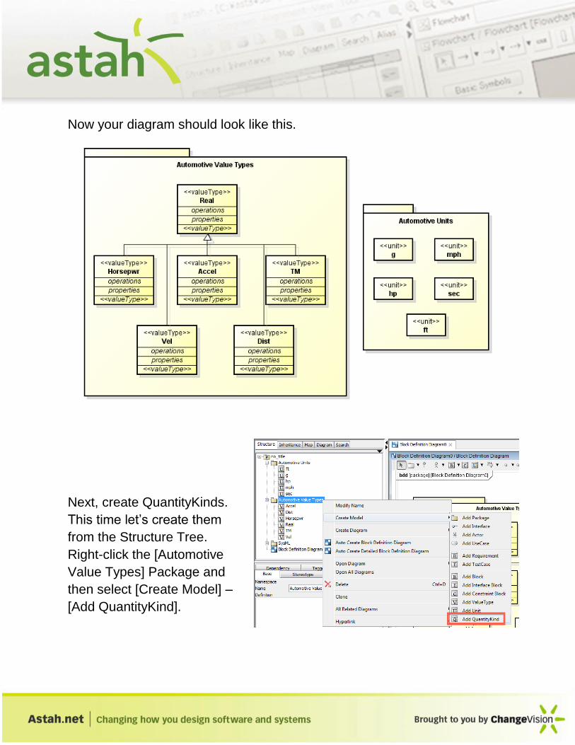
Now your diagram should look like this.
Next, create QuantityKinds.
This time let’s create them
from the Structure Tree.
Right-click the [Automotive
Value Types] Package and
then select [Create Model] –
[Add QuantityKind].

All the QuantityKind will be made under the [Automotive Value Types].
After all the QuantityKind is made, set each
QuantityKind to the Units. To do so, select the
Unit in the diagram and go to the [Base] tab of
its property view, open the drop-down list and
set each Unit to QuantityKind. Below is the
figure setting “Time” QuantityKind to the “sec”
Unit.
After the QuantityKind is set in the Property View,
the QuantityKind information appears within the
Units in the diagram.

You have now completed the first Block Definition Diagram, name this
diagram “ModelingDomain”. To do this, select the “Block Definition
Diagram0” in the Structure tree and type in the [Base] tab of its Property
view.
For more practice, let’s draw another Block Definition Diagram and create
Blocks to define the fuel flow properties of the “PowerSubsystem”.
(From P.179 Figure.B.23 of OMG SysML 1.2)
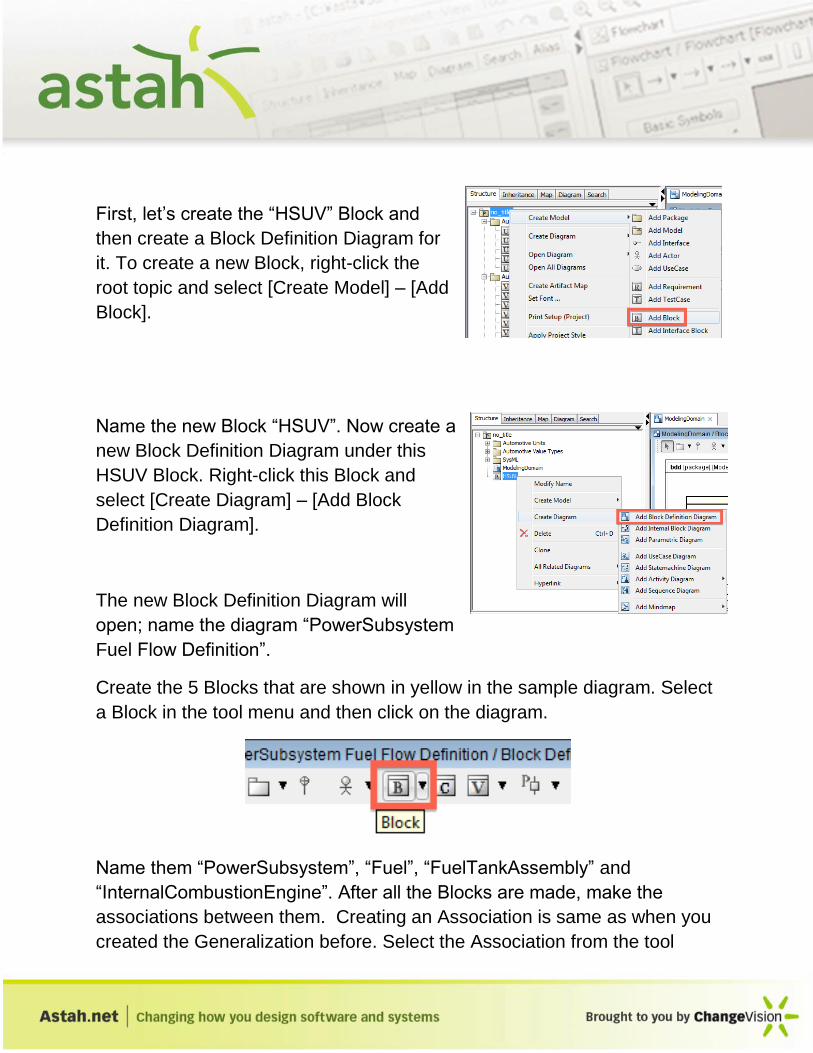
First, let’s create the “HSUV” Block and
then create a Block Definition Diagram for
it. To create a new Block, right-click the
root topic and select [Create Model] – [Add
Block].
Name the new Block “HSUV”. Now create a
new Block Definition Diagram under this
HSUV Block. Right-click this Block and
select [Create Diagram] – [Add Block
Definition Diagram].
The new Block Definition Diagram will
open; name the diagram “PowerSubsystem
Fuel Flow Definition”.
Create the 5 Blocks that are shown in yellow in the sample diagram. Select
a Block in the tool menu and then click on the diagram.
Name them “PowerSubsystem”, “Fuel”, “FuelTankAssembly” and
“InternalCombustionEngine”. After all the Blocks are made, make the
associations between them. Creating an Association is same as when you
created the Generalization before. Select the Association from the tool

menu and then click the two Blocks you want to connect. Let’s draw one
between the “PowerSubsystem” and “FuelTankAssembly” Blocks. The
association is a Composition, so select the “Composition” from the tool bar.
Click “PowerSubsystem” and then “FuelTankAssembly” and create another
one - click “PowerSubsystem” and then “InternalCombustionEngine”.
To make these Compositions in one line like the sample diagram, select
both Composition lines and then select [Line Style] – [Line (Right Angle)]
from the Pop-up menu.

The Composition line will look like the ones below.
TIPS 3: How to set the property for Associations
There are a few ways to make the Association type. Here’s how to set it to
Compositions as an example.
1: From Pop-up menus: Right-click the
Association line and set it to
Composite from “Aggregation”.
2: From the Property View: Select the
Association Line in the diagram and go to
its Property View. Open [Association End
A/B] tab and specify it in the “Aggregation”
field.

Now let’s set the name for the
Association End. Select the
Composition line and go to its
Property View and open
[Association End A/B] tab and put
“ft” for “FuelTankAssembly” End
and “ice” for
“InternalCombustionEngine” End.
When you are on this [Association
End A/B] tab, make sure that the
Target is the end block you want to
name for.
Now add the Flow Properties to the “FuelTankAssembly”, “InternalCombustionEngine” and “FuelFlow” Blocks. There are four ways to do so.
1: From the Block’s Pop-up menu [Add Element] – [Add Flow Property]
2: By clicking the blue cross of the “flow properties” compartment of the Block

3: From [FlowProperty] of the Block’s property view
4: From the Block’s Pop-up menu in the Structure Tree
Add the Flow Properties in any way you’d like. Type its Name, specify the
Type and FlowDirection in its property view.
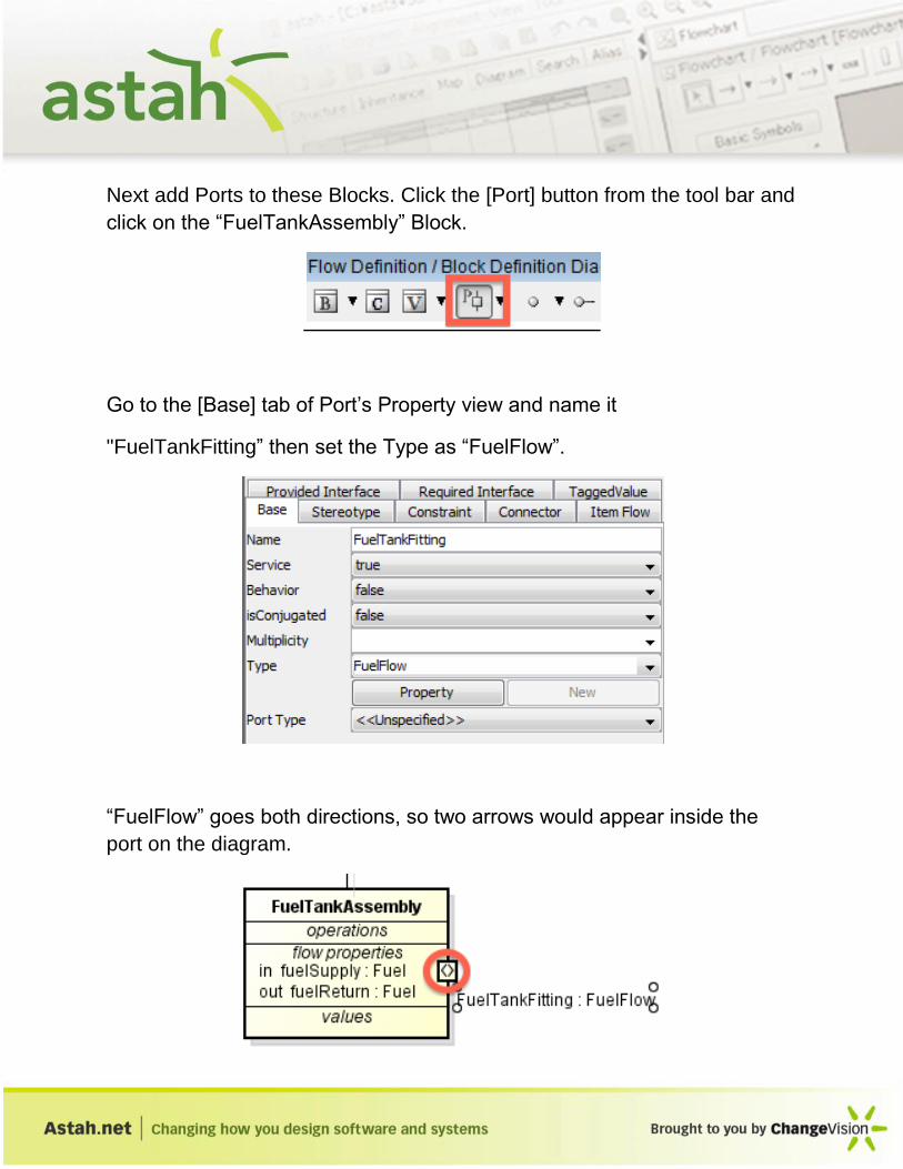
Next add Ports to these Blocks. Click the [Port] button from the tool bar and
click on the “FuelTankAssembly” Block.
Go to the [Base] tab of Port’s Property view and name it
"FuelTankFitting” then set the Type as “FuelFlow”.
“FuelFlow” goes both directions, so two arrows would appear inside the
port on the diagram.

Add another “ICEFuelFitting” Port to the “InternalCombustionEngine” just
like the one you just created.
Last, add the Values to the “Fuel” Block
(The blue Block in the diagram). To add the
Values, click the blue cross button in the
“values” compartment. Then type the two
Values as shown in the sample diagram.
When you type “Temp” and “Press” it asks
you to create a new Type, click [Yes] both times.
5: Internal Block Diagram
Let’s move to another diagram the Internal Block Diagram. Internal Block
Diagrams are used to describe the internal structure of a system in terms of
its parts, ports and connectors. In this tutorial we’ll draw the internal
structure of the “PowerSubsystem” Block.
Below is a sample of an Internal Block Diagram that you are going to draw.
(From P.68 Figure.9.3 of OMG SysML 1.2)
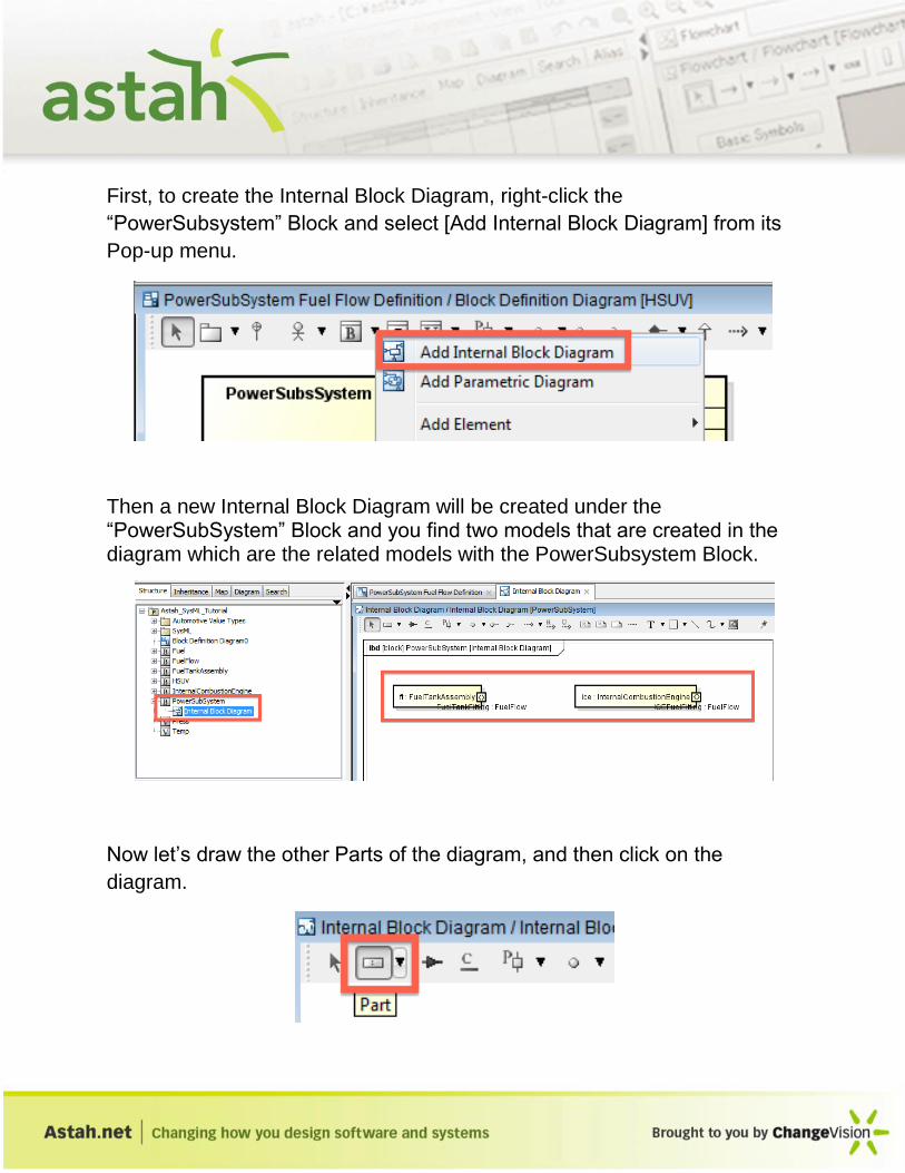
First, to create the Internal Block Diagram, right-click the
“PowerSubsystem” Block and select [Add Internal Block Diagram] from its
Pop-up menu.
Then a new Internal Block Diagram will be created under the “PowerSubSystem” Block and you find two models that are created in the diagram which are the related models with the PowerSubsystem Block.
Now let’s draw the other Parts of the diagram, and then click on the
diagram.
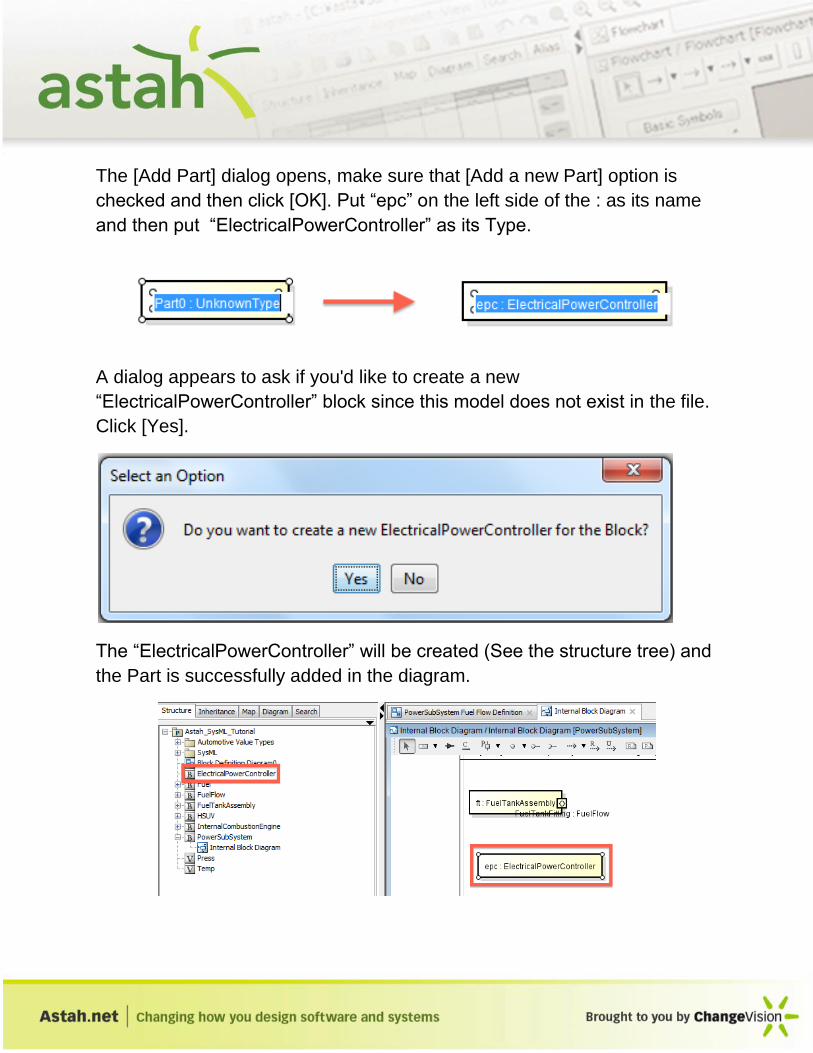
The [Add Part] dialog opens, make sure that [Add a new Part] option is
checked and then click [OK]. Put “epc” on the left side of the : as its name
and then put “ElectricalPowerController” as its Type.
A dialog appears to ask if you'd like to create a new
“ElectricalPowerController” block since this model does not exist in the file.
Click [Yes].
The “ElectricalPowerController” will be created (See the structure tree) and
the Part is successfully added in the diagram.
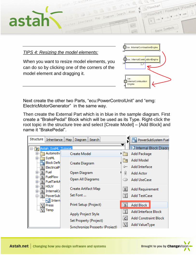
TIPS 4: Resizing the model elements:
When you want to resize model elements, you
can do so by clicking one of the corners of the
model element and dragging it.
Next create the other two Parts, “ecu:PowerControlUnit” and “emg: ElectricMotorGenerator” in the same way.
Then create the External Part which is in blue in the sample diagram. First create a “BrakePedal” Block which will be used as its Type. Right-click the root topic in the structure tree and select [Create Model] – [Add Block] and name it “BrakePedal”.

Drag the “BrakePedal” Block and drop it on to the Internal Block Diagram, then a dialog appears to ask which you’d like to create it as Internal Part or an External Part. Click “External Part” and then click [OK].
Double-click the part name and type “bkp”.
Now you have all the model elements on the diagram. Add the Ports between them the same was as you did in the Block Definition Diagram.
Once the Ports are made, add ItemFlows between the “epc” and “emg” Parts. First select the [ItemFlow] in the tool menu.

Then click one Port from the other. And create another one the other way around.
Next create a Convey to these ItemFlows. Before adding the Convey, let’s create an “ElectricCurrent” Block that we want to set as a Convey.
Select the ItemFlow and go to its Property View. Click [Add] button, then a [Refer Type] dialog opens. Select the “ElectricCurrent” and click [OK].

Create another ItemFlow the same way.
Last, let’s create the Interfaces to complete this Internal Block Diagram.
Let’s add the Provided Interface and Requirement Interface to the port of
“epc” part. There are three ways to add the Interfaces.
1: From Port’s Pop-up menu [Add Required Interface] / [Add Provided
Interface]
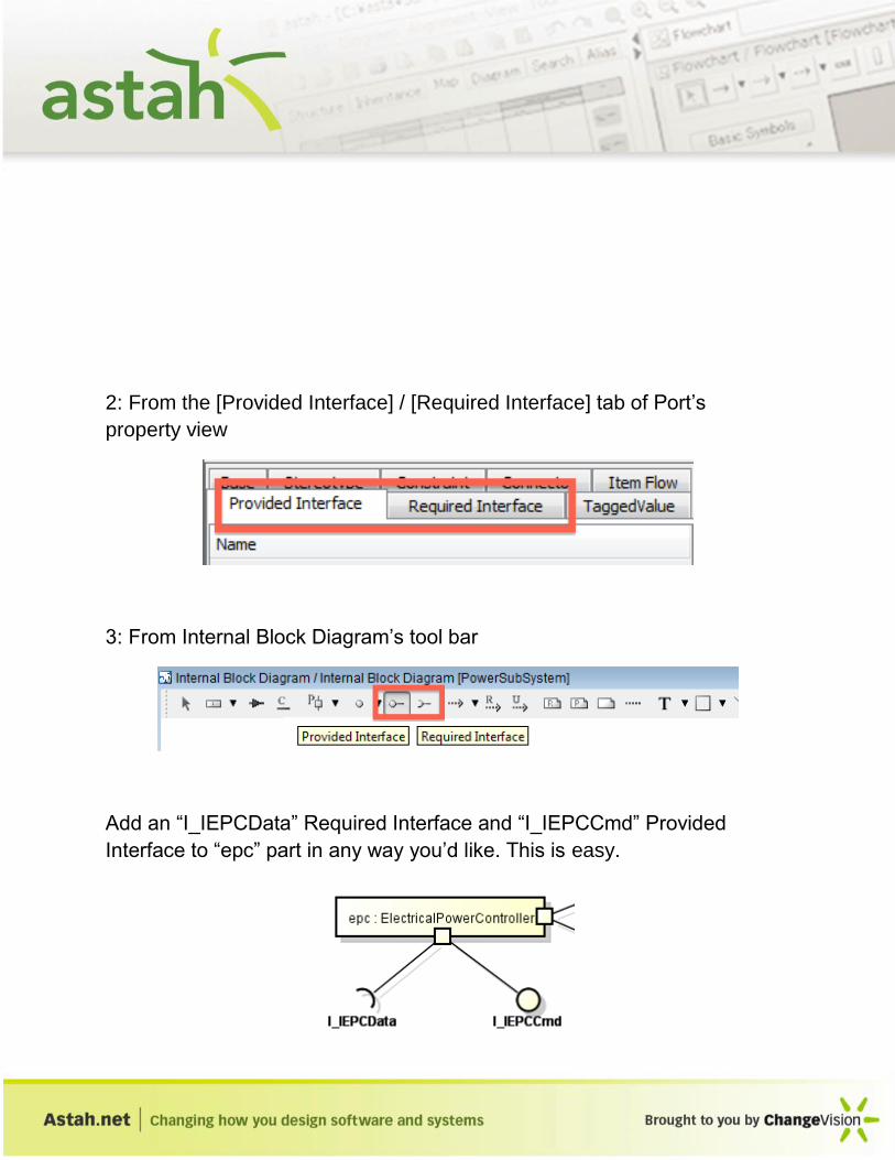
2: From the [Provided Interface] / [Required Interface] tab of Port’s
property view
3: From Internal Block Diagram’s tool bar
Add an “I_IEPCData” Required Interface and “I_IEPCCmd” Provided
Interface to “epc” part in any way you’d like. This is easy.

Now let’s add ones to the “ecu” part too. Let’s start with “I_IEPCData”
Provided Interface. To do so, select [Realization] from the tool bar.
Then click the port of “ecu” part and “I_IEPCData” Required Interface.
You will have the two Interfaces combined now, right-click it and select
“Uncombined” from its Pop-up menu.

That will separate them. Move it to the right as shown in the sample
diagram.

Now create the “I_IEPCCmd” Required Interface the same way, except you
are going to use “Usage Dependency” this time instead of “Realization”.
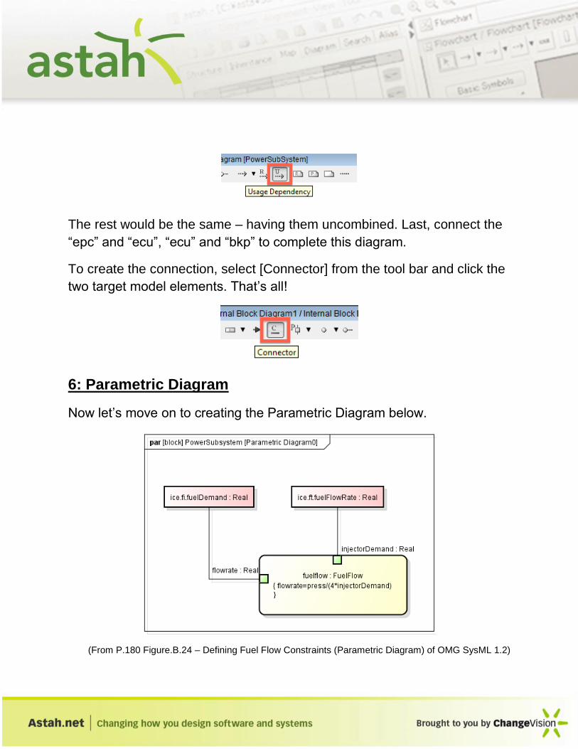
The rest would be the same – having them uncombined. Last, connect the
“epc” and “ecu”, “ecu” and “bkp” to complete this diagram.
To create the connection, select [Connector] from the tool bar and click the
two target model elements. That’s all!
6: Parametric Diagram
Now let’s move on to creating the Parametric Diagram below.
(From P.180 Figure.B.24 – Defining Fuel Flow Constraints (Parametric Diagram) of OMG SysML 1.2)

A parametric diagram is defined as a restricted form of the Internal Block Diagram. A Parametric Diagram may contain constraint properties and their parameter, along with other properties from within the Internal Block context.
Let’s create a new Parameter Diagram by Right-clicking the “PowerSubSystem” Block and selecting [Add Parametric Diagram] from its Pop-up menu.
First, draw the Constraint Property which is a property of any Block that is typed by a Constraint Block. We need a Constraint Block to do that, so let’s create one. Right-click on the root-topic and create a new Package to hold this Constraint Block from [Create Model] – [Add Package] and name it as “Constraints”. Now create a new Constraint Block in this Package by right-clicking on it, then go to [Create Model] – [Add Constraint Block] and name it as “FuelFlow”.

A Constraint Block “FuelFlow” is created. Go to [Constraint] tab of its Property View and add the constraint from the Constraint field as shown below.
Now drag the Constraint Block from the Structure Tree into the diagram editor and name it “fuelflow”.
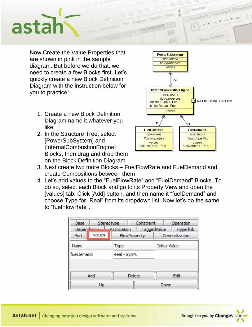
Now Create the Value Properties that are shown in pink in the sample diagram. But before we do that, we need to create a few Blocks first. Let’s quickly create a new Block Definition Diagram with the instruction below for you to practice!
1. Create a new Block Definition Diagram name it whatever you like
2. In the Structure Tree, select [PowerSubSystem] and [InternalCombustionEngine] Blocks, then drag and drop them on the Block Definition Diagram
3. Next create two more Blocks – FuelFlowRate and FuelDemand and create Compositions between them
4. Let’s add values to the “FuelFlowRate” and “FuelDemand” Blocks. To do so, select each Block and go to its Property View and open the [values] tab. Click [Add] button, and then name it “fuelDemand” and choose Type for “Real” from its dropdown list. Now let’s do the same to “fuelFlowRate”.
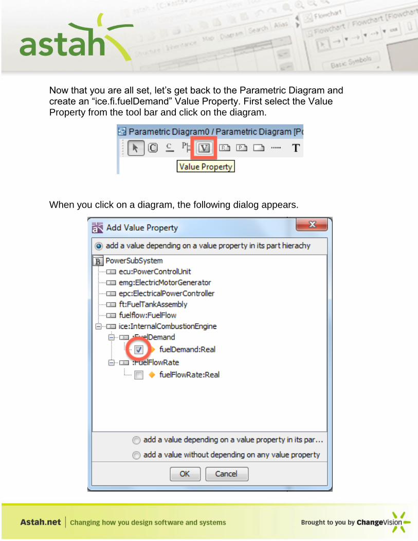
Now that you are all set, let’s get back to the Parametric Diagram and create an “ice.fi.fuelDemand” Value Property. First select the Value Property from the tool bar and click on the diagram.
When you click on a diagram, the following dialog appears.

Select “fuelDemand:Real” and then click [OK]. Now create another Value Property in a same way you just did.
Now all you need to do is to add the Value Properties and the Constraint Parameter with Binding Connector to complete this Parametric Diagram. To connect them with BindingConnector, you need to add the “Constraint Parameter” to the Constraint Properties first.
Select the “Constraint Parameter” and add it to “fuelflow” Constraint Property and name them as shown in the sample diagram.
Now select “BindingConnector” and then connect each Value Type and the Constraint Property.
You have completed this Parametric Diagram.

7: UseCase Diagram
Now let’s draw an UseCase Diagram.
(From P.166 Figure.B.6 – Establishing Operational Use Cases for “Drive the Vehicle” of OMG SysML
1.2)
To create an UseCase Diagram, select [Diagram] – [UseCase Diagram] from Main menu.
First, create an Actor. Select [Actor] from tool bar then click on the diagram and name it as “Driver”. Create the 6 UseCases in the same way.
After all the model elements are created, make the relationships between them.
First, between the Actor and two UseCases in blue, you want to connect them with Association line.

Use “Extend” and “Include” for connecting all the UseCases to complete the diagram.
8: Requirement Diagram
The last diagram in this tutorial which we’ll cover is a Requirement Diagram. Let’s organize the requirements and test cases regarding the “HSUV” using the Requirement Diagram. The sample diagram is below.
(From P.1172 Figure.B.13 – Acceleration Requirement Relationships of OMG SysML 1.2)
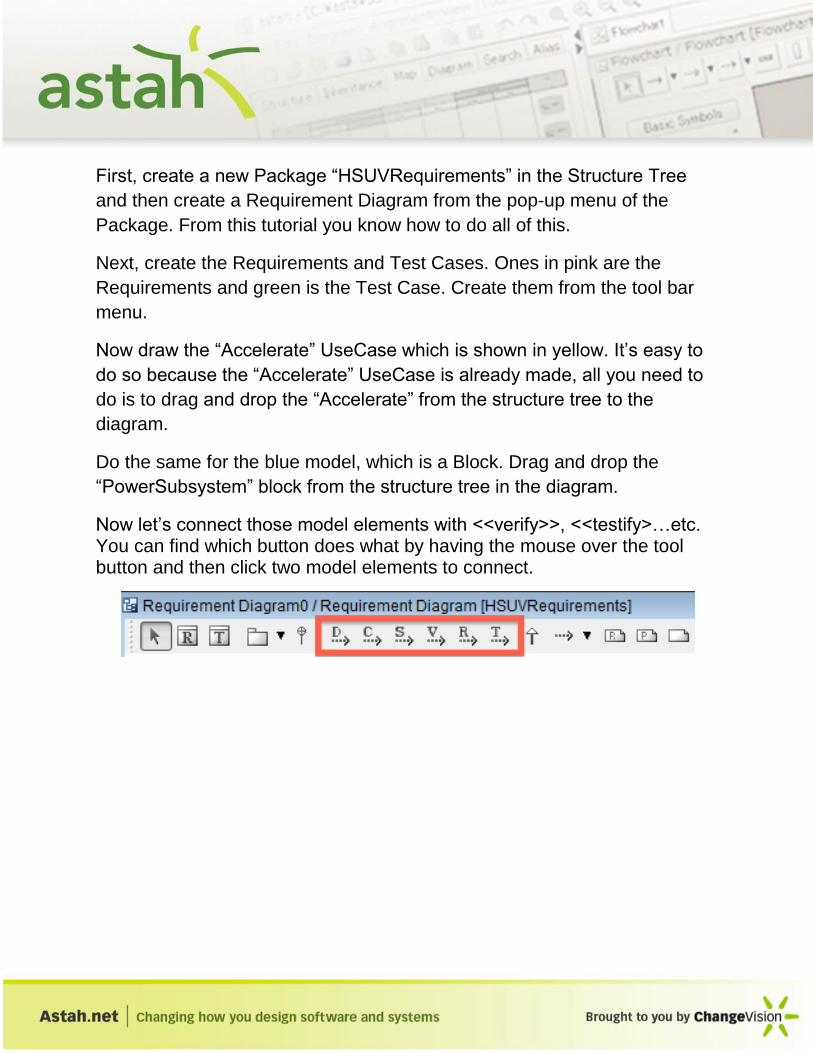
First, create a new Package “HSUVRequirements” in the Structure Tree
and then create a Requirement Diagram from the pop-up menu of the
Package. From this tutorial you know how to do all of this.
Next, create the Requirements and Test Cases. Ones in pink are the
Requirements and green is the Test Case. Create them from the tool bar
menu.
Now draw the “Accelerate” UseCase which is shown in yellow. It’s easy to
do so because the “Accelerate” UseCase is already made, all you need to
do is to drag and drop the “Accelerate” from the structure tree to the
diagram.
Do the same for the blue model, which is a Block. Drag and drop the
“PowerSubsystem” block from the structure tree in the diagram.
Now let’s connect those model elements with <<verify>>, <<testify>…etc. You can find which button does what by having the mouse over the tool button and then click two model elements to connect.

9: Thanks!
Thank you for reading through this tutorial. With this tutorial, you must have experienced enough operations to learn the basic features to draw diagrams with Astah SysML. We’ll keep updating this tutorial with more content in future.
Below is a list of features that didn’t appear in this tutorial but could be useful for your needs.
- Set default color for each model element - Set default color by stereotypes - Export diagrams to PNG/JPEG/EMF/SVG image files - Set Hyperlinks - Create Mindmaps and convert Mindmaps to SysML diagrams..etc.
If you have any questions or feature requests for Astah SysML please feel free to send them over to us at anytime!
Contact us : http://astah.net/contact-us
- Astah SysML Development Team