Tutorial for stress analysis of a single-stage helical ... · PDF fileTutorial for stress...
24
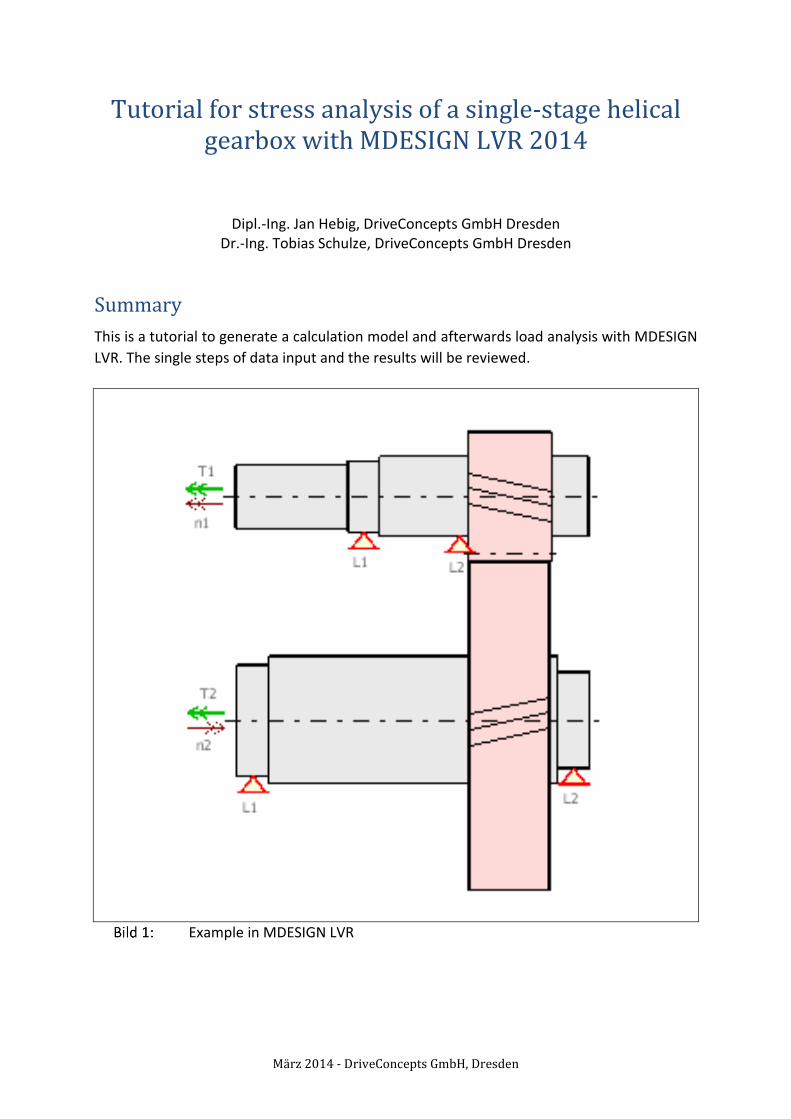
März 2014 - DriveConcepts GmbH, Dresden Tutorial for stress analysis of a single-stage helical gearbox with MDESIGN LVR 2014 Dipl.-Ing. Jan Hebig, DriveConcepts GmbH Dresden Dr.-Ing. Tobias Schulze, DriveConcepts GmbH Dresden Summary This is a tutorial to generate a calculation model and afterwards load analysis with MDESIGN LVR. The single steps of data input and the results will be reviewed. Example in MDESIGN LVR
Transcript of Tutorial for stress analysis of a single-stage helical ... · PDF fileTutorial for stress...
Detailed load analysis in gears with MDESIGN LVR
März 2014 - DriveConcepts GmbH, Dresden
Tutorial for stress analysis of a single-stage helical gearbox with MDESIGN LVR 2014
Dipl.-Ing. Jan Hebig, DriveConcepts GmbH Dresden Dr.-Ing. Tobias Schulze, DriveConcepts GmbH Dresden
Summary
This is a tutorial to generate a calculation model and afterwards load analysis with MDESIGN
LVR. The single steps of data input and the results will be reviewed.
Example in MDESIGN LVR

Detailed load analysis in gears with MDESIGN LVR
März 2014 - DriveConcepts GmbH, Dresden
1. Index
Inhaltsverzeichnis
1. Index ............................................................................................................................................ 2
2. Start ............................................................................................................................................. 3
3. Input of the gear data .................................................................................................................. 4
3.1. Gearing parameters ................................................................................................................. 4
3.2. Shaft and bearing data ............................................................................................................ 8
3.3. Modifications and deviations ................................................................................................. 12
3.4. Data for the contact temperature clculation ........................................................................... 15
3.5. Time-depending load curves ................................................................................................. 16
4. Calculation ................................................................................................................................. 17
4.1 Results in LVR ....................................................................................................................... 17
4.2 Results in MDESIGN ............................................................................................................. 18
5. Documentation .......................................................................................................................... 20
6. Literature .................................................................................................................................... 22

Detailed load analysis in gears with MDESIGN LVR
März 2014 - DriveConcepts GmbH, Dresden
2. Start
Start the software MDESIGN and select in the left explorer bar in the folder MDESIGN LVR the entry MDESIGN LVR and start it by using a double click. Start a new project by clicking on the main button new reset. All data on the input screen will be set to a default value. Save the dataset LVR (*lvr) into a folder. To save again the dataset has to be overwritten. The input masks can be set by the dropdown menu. The entry “All parameters” opens an overview of all parameters. Otherwise are the information of gear, modification, shaft, temperature and lubrication and load curves filled in, in any sequence.
Select input page
The most significant option is the number of gear stages and the selection of the current stage. In the input mask of the software only the current stage can be defined and calculated.
Define gear stages
The direction of rotation causes also a change of the active flank modifications. The modifications are always depending to the active flank.

Detailed load analysis in gears with MDESIGN LVR
März 2014 - DriveConcepts GmbH, Dresden
3. Input of the gear data
3.1. Gearing parameters The data of the tooth profile, tool and load has to be defined in the respective groups. A thin rimmed gear geometry can be defined if required.
Tooth profile
Tool

Detailed load analysis in gears with MDESIGN LVR
März 2014 - DriveConcepts GmbH, Dresden
Nominal load and thin rimmed gear
2D calculation model
In the 2D calculation model, in the right corner, the data input can be controlled. The position of the single gear elements (gear, shaft, bearing) as well as the rotation direction and helix angle are displayed. Additional helpful functions are stored in the button Actions. The tooth profile as well as animated gear pair meshing’s.

Detailed load analysis in gears with MDESIGN LVR
März 2014 - DriveConcepts GmbH, Dresden
Actions button
Tooth contour

Detailed load analysis in gears with MDESIGN LVR
März 2014 - DriveConcepts GmbH, Dresden
Meshing of the gear pair

Detailed load analysis in gears with MDESIGN LVR
März 2014 - DriveConcepts GmbH, Dresden
3.2. Shaft and bearing data The design of shaft and bearing can be done in the 2D shaft editor.
Graphical input of the shaft design
To build a realistically shaft design, from the Data explorer (entry “Data explorer” in the toolbar) can be added shaft sections, bearings and loads. The elements can be dragged across the surface by pressed mouse button. On the left side of the graphic window the selected element can be edited in its parameters. In example the shaft length, diameter, position etc. The geometry of the tooth will be transferred from the module “gear data” for generating the gear wheel. They can’t be modified in the shaft editor.

Detailed load analysis in gears with MDESIGN LVR
März 2014 - DriveConcepts GmbH, Dresden
Graphical input of the shaft geometry
For modelling the shaft geometry it is recommended to drag the bearing and toothing entirely to the left side to avoid error messages due overlapping of shaft section, toothing and bearing.
Modelling the shaft geometry of shaft 1

Detailed load analysis in gears with MDESIGN LVR
März 2014 - DriveConcepts GmbH, Dresden
Shaft section Length [mm] Outer diameter [mm]
1 70 40
2 20 45
3 130 50
Geometry of shaft 1 Afterwards the position of the toothing and the bearing can be set correctly.
- Position toothing: 145 mm - Bearing 1: position: 80 mm, stiffness: 500 N/µm, offset: 0 mm - Bearing 2: position: 140 mm, stiffness: 500 N/µm, offset: 0 mm
Korrect modell of shaft 1
The radial bearing stifness as well as any clearance/offset can defined in the parameters of
the bearing.
Afterwards the shaft 2 is defined in the same way.
Shaft section Length [mm] Outer diameter [mm]
1 20 70
2 180 80
3 20 60
Geometry of shaft 1
- Position toothing: 145 mm - Bearing 1: position: 10 mm, stiffness: 700 N/µm, offset: 0 mm - Bearing 2: position: 210 mm, stiffness: 700 N/µm, offset: 0 mm
Correct modell of shaft 2

Detailed load analysis in gears with MDESIGN LVR
März 2014 - DriveConcepts GmbH, Dresden
The side of torque output can be changed due the ratio leftside/total at the torque arrow. E modulus (210.000 MPa) and Poisson’s ratio (0,3) of the shaft has to be set in the static input under “Nominal load and miscellaneous”. Additional loads and bending moments ca be addet due the graphical input.

Detailed load analysis in gears with MDESIGN LVR
März 2014 - DriveConcepts GmbH, Dresden
3.3. Modifications and deviations The modifications and deviations have to be set to zero.
Profile modifications
Lead modifications

Detailed load analysis in gears with MDESIGN LVR
März 2014 - DriveConcepts GmbH, Dresden
Deviations The parameter “Profile angle deviation” has to be set to the correction amount of the “Helix angle deviation”.
Action button To check the modifications there are three modification graphics.

Detailed load analysis in gears with MDESIGN LVR
März 2014 - DriveConcepts GmbH, Dresden
Modification graphics

Detailed load analysis in gears with MDESIGN LVR
März 2014 - DriveConcepts GmbH, Dresden
3.4. Data for the contact temperature clculation In the input „Temperature / lubrication“ the data for the gear lubrication has to be defined.
Definition of the lubricaions

Detailed load analysis in gears with MDESIGN LVR
März 2014 - DriveConcepts GmbH, Dresden
3.5. Time-depending load curves In the input „time-depending load curves“ the possible time courses for the tangential force of toothing or additionel shaft loads can be defined. The ISO6336 values allows a fast convertation of the in software used coordinate L into the diameter of gear or path of action.
Time-depending load curves
ISO6336 values

Detailed load analysis in gears with MDESIGN LVR
März 2014 - DriveConcepts GmbH, Dresden
4. Calculation
By pressing the function button F10 on keyboard or the Calculate button the calculation in the toolbar starts the calculation.
4.1 Results in LVR After confirmation a seccond window with the results of the load distribution appears.
- Load intensity
- Flank pressure
- Root stress gear
- Contact temperature
- Effective deviation of gear
- Effective deviation of gear pair
- Substitute curvature radius
- Biegelinien
- …
Ergebnissausgabe im LVR
In the marked selection menu the plots for flank pressure, contact temperature etc. can be choosen.
Additional results (Shaft bending, total transmission error, etc.) can be shown by clicking on the entry
“Diagr.”.
Detailed load analysis in gears with MDESIGN LVR
März 2014 - DriveConcepts GmbH, Dresden
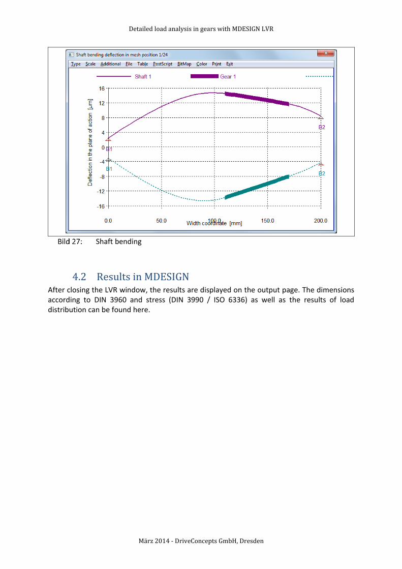
Shaft bending
4.2 Results in MDESIGN After closing the LVR window, the results are displayed on the output page. The dimensions according to DIN 3960 and stress (DIN 3990 / ISO 6336) as well as the results of load distribution can be found here.

Detailed load analysis in gears with MDESIGN LVR
März 2014 - DriveConcepts GmbH, Dresden
Results on output page

Detailed load analysis in gears with MDESIGN LVR
März 2014 - DriveConcepts GmbH, Dresden
5. Documentation
For documentation of the input data and calculation results, they can be printed or safed as a *.rtf,
*.html or *.pdf-file. The *.rtf-file can be read and edited by Microsoft Word. A print preview can be
displayed by the respective entry in the menu.
Seitenansicht
The available result plots can be included too. Therefore select the menu entry “BMP” “bitmap
graphic ---> calculation document” and mark the desired plots. They would be transferred to the output
file.

Detailed load analysis in gears with MDESIGN LVR
März 2014 - DriveConcepts GmbH, Dresden
Transferring the LVR results to documentation

Detailed load analysis in gears with MDESIGN LVR
März 2014 - DriveConcepts GmbH, Dresden
6. Literature
[1] Börner, J., Senf, M., Linke, H.; Beanspruchungsanalyse bei Stirnradgetrieben – Nutzung der Berechnungssoftware LVR; Vortrag DMK 2003, Dresden, 23. und 24. September 2003
[2] Baumann, F, Trempler U.: Analyse zur Beanspruchung der Verzahnung von Planetengetrieben, Vortrag DMK 2007, Dresden
[3] Börner, J.: Modellreduktion für Antriebssysteme mit Zahnradgetrieben zur vereinfachten Berechnung der inneren dynamischen Zahnkräfte. Dissertation TU Dresden, 1988
[4] Börner, J.; Senf, M.: Verzahnungsbeanspruchung im Eingriffsfeld – effektiv berechnet. Antriebstechnik 34, 1995, 1
[5] Börner, J.: Genauere Analyse der Beanspruchung von Verzahnungen. Beitrag zur Tagung „Antriebstechnik, Zahnradgetriebe“, Dresden, 09/2000
[6] Bulligk, Chr.: Theoretische Untersuchung zur modularisierten Berechnung und Auslegung von Getrieben, Diplomarbeit, DriveConcepts GmbH, 2009
[7] CalculiX: freies FEM Programm , MTU Aero-engenier-GmbH, (www.calculix.de);
[8] Gajewski, G.: Untersuchungen zum Einfluss der Breitenballigkeit auf die Tragfähigkeit von Zahnradgetrieben. Dissertation TU Dresden, 1984
[9] Gajewski, G.: Ermittlung der allgemeinen Einflussfunktion für die Berechnung der Lastverteilung bei Stirnrädern. Forschungsbericht, TU Dresden, Sektion Grundlagen des Maschinenwesens, 1984
[10] Hartmann-Gerlach, Christian: Erstellung eines Berechnungskerns für die Software MDESIGN LVRplanet. Unveröffentlichte interne Arbeit, DriveConcepts GmbH 2007
[11] Hartmann-Gerlach, Christian: Verformungsanalyse von Planetenträgern unter Verwendung der Finiten Elemente Methode. Unveröffentlichte interne Arbeit, DriveConcepts GmbH 2008
[12] Hartmann-Gerlach, Christian: Effiziente Getriebeberechnung von der Auslegung bis zur Nachrechnung mit MDESIGN gearbox und MDESIGN LVRplanet, Vortrag anlässlich des SIMPEP Kongresses in Würzburg, 18.-19. Juni 2009
[13] Heß, R.: Untersuchungen zum Einfluss der Wellen und Lager sowie der Lagerluft auf die Breitenlastverteilung von Stirnradverzahnungen. Diss. TU Dresden, 1987
[14] Hohrein, A.; Senf, M.: Reibungs-, Schmierungs-, Verschleiß- und Festigkeitsuntersuchungen an Zahnradgetrieben. Forschungsbericht TU Dresden, 1977
[15] Hohrein, A.; Senf, M.: Untersuchungen zur Last- und Spannungsverteilung an schrägverzahnten Stirnrädern. Diss. TU Dresden, 1978
[16] Linke, H.: Untersuchungen zur Ermittlung dynamischer Zahnkräfte. Diss. TU Dresden, 1969
[17] Linke, H.: Stirnradverzahnung – Berechnung, Werkstoffe, Fertigung. München, Wien : Hanser, 1996

Detailed load analysis in gears with MDESIGN LVR
März 2014 - DriveConcepts GmbH, Dresden
[18] Linke, H.; Mitschke, W.; Senf, M.: Einfluss der Radkörpergestaltung auf die Tragfähigkeit von Stirnradverzahnungen. In: Maschinenbautechnik 32 (1983) 10, S 450-456
[19] Neugebauer, G.: Beitrag zur Ermittlung der Lastverteilung über die Zahnbreite bei schrägverzahnten Stirnrädern. Dissertation TU Dresden, 1962
[20] Oehme, J.: Beitrag zur Lastverteilung schrägverzahnter Stirnräder auf der Grundlage experimenteller Zahnverformungsuntersuchungen. Diss. Technische Universität Dresden. 1975
[21] Polyakov, D..; Entwicklung eines durchgängigen Rechenmodells zur Bestimmung der Gehäusesteifigkeit unter Verwendung der FE Methode, Diplomarbeit, DriveConcepts GmbH
[22] Schlecht, B., Hantschack, F., Schulze, T.; Einfluss der Bohrungen im Kranz auf die Tragfähigkeit von Hohlradverzahnungen; Antriebstechnik 41 (2002), Teil I, Heft 12, S. 45-47; Antriebstechnik 42 (2003), Teil II, Heft 2, S. 51-55
[23] Schlecht, B. Senf, M.; Schulze, T.: Beanspruchungsanalyse bei Stirnradgetrieben und Planetengetrieben - Haus der Technik e.V., Essen, 09./10. März 2010
[24] Schlecht, B.; Schulze, T.; Hartmann-Gerlach, C.: Berechnung der Lastverteilung in Planetengetrieben unter Berücksichtigung aller relevanten Einflüsse - Zeitschriftenbeitrag Konstruktion 06/2009 S12.ff, DriveConcepts GmbH, 2009
[25] Schulze, Tobias: Getriebeberechnung nach aktuellen wissenschaftlichen Erkenntnissen, Vortrag anlässlich des Dresdner Maschinenelemente DMK2007 in Dresden, DriveConcepts GmbH, 2007
[26] Schulze, Tobias: Load Distribution in planetary gears under consideration of all relevant influences, Vortrag anlässlich JSME International Conference on Motion and Power Transmissions, Sendai (Japan), 13.-15. Mai 2009
[27] Schulze, Tobias: Berechnung der Lastverteilung in Planetengetrieben unter Berücksichtigung aller relevanten Einflüsse, Vortrag auf KT2009 in Bayreuth zur Lastverteilung in Planetengetrieben, 08.-09.10.2009
[28] Schulze, Tobias: Ganzheitliche dynamische Antriebsstrangsbetrachtung von Windenergieanlagen. Sierke Verlag 2008, Dissertation TU Dresden
[29] Schulze, Tobias: Load distribution in planetary gears. Danish gear society “Gearteknisk InteresseGruppe”, 11th february 2010 at SDU in Odense, Denmark
[30] Schulze, Tobias: Calculation of load distribution in planetary gears for an effective gear design process. AGMA Fall Technical Meeting 2010, October 17-19, 2010, Milwaukee Wis, USA
Normen | Standards
[31] DIN 867:1986 – Bezugsprofile für Evolventenverzahnungen an Stirnrädern (Zylinderrädern) für den allgemeinen Maschinenbau und den Schwermaschinenbau.
[32] DIN 3960:1987 – Begriffe und Bestimmungsgrößen für Stirnräder (Zylinderräder) und Stirnradpaare (Zylinderpaare) mit Evolventenverzahnung.

Detailed load analysis in gears with MDESIGN LVR
März 2014 - DriveConcepts GmbH, Dresden
[33] Beiblatt 1 zu DIN 3960:1980 – Begriffe und Bestimmungsgrößen für Stirnräder (Zylinderräder) und Stirnradpaare (Zylinderpaare) mit Evolventenverzahnung; Zusammenstellung der Gleichungen
[34] DIN 3990:1987, Teil 1 - 5 Tragfähigkeit von Stirnrädern.
[35] DIN 743:2008 T1-T4 & Beiblatt 1,2 Tragfähigkeitsberechnung von Wellen und Achsen
[36] DIN ISO 281:2009 Wälzlager – Dynamische Tragzahlen und nominelle Lebensdauer - Berechnung der modifizierten nominellen Referenz-Lebensdauer für Wälzlager
[37] ISO 6336:2008 Calculation of load capacity of spur and helical gears
[38] VDI 2737:2005, Berechnung der Zahnfußtragfähigkeit von Innenverzahnungen mit Zahnkranzeinfluss, VDI-Richtlinie
Software
[39] MDESIGN® LVR 2014, software for load distribution of multi stage spur- and helical gears. DriveConcepts GmbH, 2014
[40] MDESIGN® LVRplanet 2014, software for load distribution of planetary gear stages. DriveConcepts GmbH, 2014
[41] MDESIGN® gearbox 2014, design and calculation software for multi stage gearboxes. DriveConcepts GmbH, 2014