Tutorial 9: Advanced shape grammar - Esri Support...
13
Tutorial 9: Advanced shape grammar Copyright © 1995-2015 Esri. All rights reserved.
Transcript of Tutorial 9: Advanced shape grammar - Esri Support...

Tutorial 9: Advanced shapegrammar
Copyright © 1995-2015 Esri. All rights reserved.
Table of ContentsTutorial 9: Advanced shape grammar . . . . . . . . . . . . . . . . . . . . . . . . . . . . . . . . . . . . . 3
Tutorial 9: Advanced shape grammar
Copyright © 1995-2015 Esri. All rights reserved. 2

Tutorial 9: Advanced shape grammarDownload items
• Tutorial data
• Tutorial PDF
Complex facade patterns
This tutorial shows how to model a building from a picture and introduces some more complex CGA techniques.
Tutorial setup
Open the ComplexPatterns.cej scene if it's not already open.
Generate the building
This tutorial explains how to create a set of CGA rules to recreate a building from a real-world photograph with pure CGA. The facadeyou're going to model is shown in the following photograph. Due to the tricky patterns of the tile and window layout in this example,you'll need to use some advanced CGA mechanisms such as nested repeat splits and parameter passing.
GCA perspective of the generated building:
Tutorial 9: Advanced shape grammar
Copyright © 1995-2015 Esri. All rights reserved. 3

To generate the building in advance:
Steps:
1. Select one of the lots in the 3D viewport.
2. Click the generate button from the top toolbar.
Facade analysis
When planning a new CGA rule, it's helpful to sketch the crude layout and define some of the shape names before starting to writethe rules.
The facade you'll model consists mainly of three floor types: top, ground, and upper. The lower floors are made of tiles containingwindows, whereas the top floor only contains window elements. Every other lower floors is identical, so you'll pass the index (thefloorIndex) with the Floor shape to create the correct look (tile and window alignment) for a specific floor.
Due to the pattern of the tiles, you'll define an intermediate DoubleTile shape, which contains two Tile shapes and which will behelpful once you encode the floor patterns.
Tutorial 9: Advanced shape grammar
Copyright © 1995-2015 Esri. All rights reserved. 4
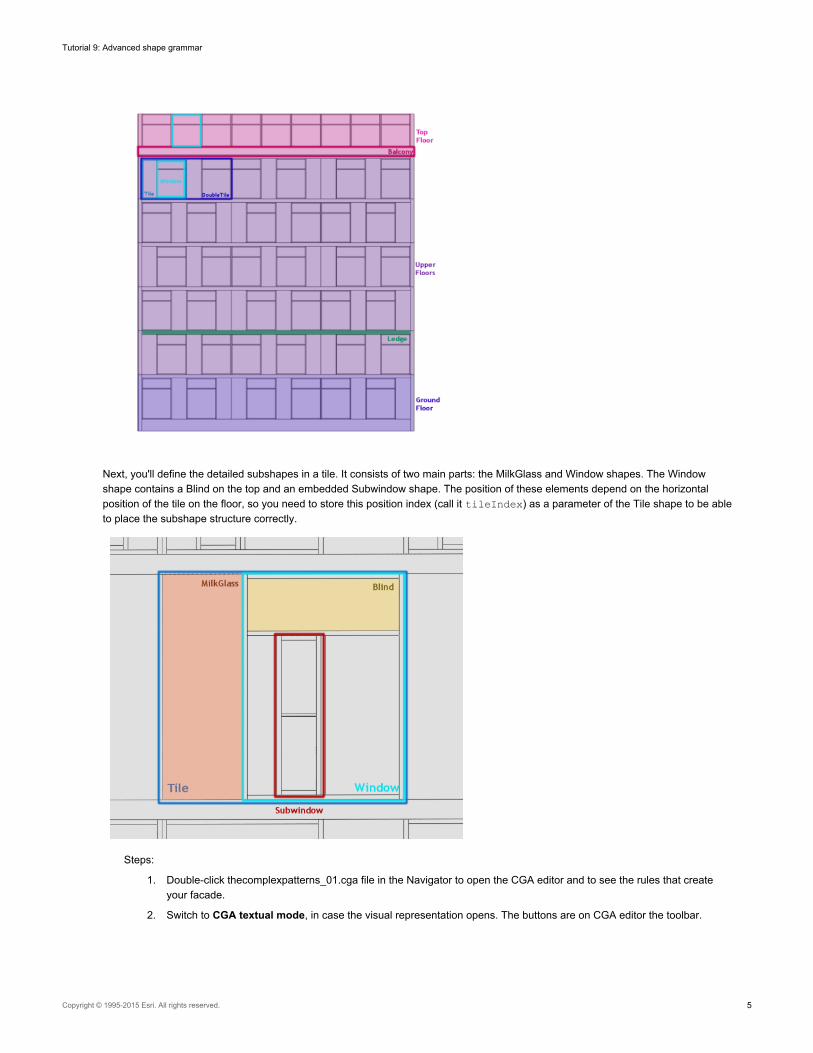
Next, you'll define the detailed subshapes in a tile. It consists of two main parts: the MilkGlass and Window shapes. The Windowshape contains a Blind on the top and an embedded Subwindow shape. The position of these elements depend on the horizontalposition of the tile on the floor, so you need to store this position index (call it tileIndex) as a parameter of the Tile shape to be ableto place the subshape structure correctly.
Steps:
1. Double-click thecomplexpatterns_01.cga file in the Navigator to open the CGA editor and to see the rules that createyour facade.
2. Switch to CGA textual mode, in case the visual representation opens. The buttons are on CGA editor the toolbar.
Tutorial 9: Advanced shape grammar
Copyright © 1995-2015 Esri. All rights reserved. 5

Attributes, variables, and assets
Attributes are defined at the beginning of the rule file. These attributes are used through the entire rule set and can be modified viathe Windows > Inspector outside the CGA Grammar Editor.
// User Attribute
@Group("Building", 1) @Range(5,40)attr buildingH = 27 // building height
@Group("Facade", 2) @Range(3,6)attr floorH = 3.5 // floor height@Group("Facade") @Range(3,6)attr groundfloorH = floorH + 1 // groundfloor height@Group("Facade") @Range(1,4)attr nSymmetries = 2@Group("Facade") @Range(0.1,1)attr borderwallW = 0.3 // width of border wall stripe@Group("Facade") @Range(0.1,0.8)attr ledgeH = 0.3 // ledge height
@Group("Window",3) @Range(1,5)attr windowW = 2.5 // window width@Group("Window") @Range(1,5)attr milkGlassW = windowW/2 // milkglass blend width@Group("Window") @Range(0.1,2.5)attr blindH = 0.8 // blind height@Group("Window") @Range(0.01,0.5)attr frameW = 0.07 // frame width
@Group("Balcony",4) @Range(3,6)attr balconyDepth = 2
@Group("Colors",5)attr brightblue = "#86b1c7"@Group("Colors",5)attr darkblue= "#33556c"@Group("Colors",5)attr red = "#5c3f40"@Group("Colors",5)attr grey ="#6b7785"@Group("Colors",5)attr white = "#ffffff"
Annotations such as @Group or @Range are added to attributes to control their appearance in the Inspector.
Other variables and assets are defined in the following block:
tileW = windowW + milkGlassW // total tile widthconst barDiameter = 0.04
// assetsconst cyl_v = "general/primitives/cylinder.vert.8.notop.tex.obj"const cyl_h = "general/primitives/cylinder.hor.8.notop.tex.obj"const window_tex = "facade/windows/1_glass_2_blue.tif"const milkGlass_tex = "facade/windows/blend_tex.png"
Tutorial 9: Advanced shape grammar
Copyright © 1995-2015 Esri. All rights reserved. 6

The actual creation of the building starts now. First, the mass model is created with the extrude operation. The top floor is split fromthe main part and split again to create the set-back balcony.
Lot -->extrude(buildingH) // Extrude the buildingsplit(y){ ~1: MainPart | floorH: UpperPart } // Split top floor from lower floors
UpperPart -->split(z){ ~1: TopFloor | balconyDepth: Balcony } // Create a set-back by splitting in the direction of the building depth
Component splits are applied then to the different volume parts to distinguish the front, side and top faces and to trigger facade, walland roof rules.
MainPart -->comp(f){ front: Facade | side: Wall | top: Roof } // Create a facade on the front face, walls on the side faces, and a roof on the top face
TopFloor -->comp(f){ front: Floor(-1) | side: Wall | top: Roof } // Create a floor (marked with -1 as top floor) on the front face, walls on the side and roof on the top face
The dimensions of the balcony are set. The railing will be placed on the faces of the current shape, so you'll use a component split toget the front, left, and right faces for the Railing rule.
Balcony -->s(scope.sx-2*borderwallW,0.7,scope.sz-borderwallW) center(x) // Set balcony height to 0.7 meters (railing height)comp(f){ front: Railing | left: Railing | right: Railing }
Crude building shape after volume modeling:
Facade and floors
You'll now subdivide the front facade further. The first split subdivides the facade into a ground floor part and a set of upper floors withthe help of a repeating split {...}*. The tilde sign (~) before the split size (for example, ~groundfloorH) allows a flexible height andensures matching floors with no holes in the facade. By passing thesplit.index (which represents the floor index) as a parameter,you can later trigger specific floor features.
Facade -->// Split the facade into a groundfloor and repeated upper floors
// (all floors are marked with their split index, which represents the floor number)split(y){ ~groundfloorH: Floor(split.index) | { ~floorH: Floor(split.index) }* }
Every floor has a narrow wall area on its left and right borders. You'll create this with a simple split in x-direction.
Tutorial 9: Advanced shape grammar
Copyright © 1995-2015 Esri. All rights reserved. 7

Floor(floorIndex) -->// create a narrow wall element on both sides of every floor.//the floorIndex parameter is passed on to be used latersplit(x){borderwallW: Wall | ~1: FloorSub(floorIndex) | borderwallW: Wall }
Depending on the floor index, special horizontal elements are now created for every floor with horizontal split commands:
• The upper floors only feature a top ledge.
• The top floor has no additional elements and triggers the TileRow shape directly.
• You'll use the floor index again in a later rule, so ass it again as a parameter with the TileRow shape.
FloorSub(floorIndex) -->case floorIndex == 0: // ground floor with index 0.
split(y){ 1: Wall | ~1: TileRow(floorIndex) | ledgeH: Wall}case floorIndex > 0: // upper floors
split(y){ ~1: TileRow(floorIndex) | ledgeH: Ledge }else: // topfloor with index -1.
TileRow(floorIndex)
Facade with floor and ledge splits:
Tiles
You'll now split the floors into tiles. For the top floor, it's relatively easy; there is no special pattern, just repeating window elements. Toaddress these tiles later, you mark them with the parameter -1.
To create the special repeating pattern for the main floors, you'll create an intermediate shape called DoubleTile. To align thewindow elements correctly in a later step, you need the floor and the tile index (split.index), which you pass as parameters.
TileRow(floorIndex) -->case floorIndex == -1:
split(x){ ~windowW: Tile(-1) }*// Repeating shape Tiles on the top floor, marked again with -1
else:split(x){ ~tileW*nSymmetries: DoubleTile(floorIndex,split.index) }*
// the floor is subdivided into regular DoubleTile shapes, the floor index is passed as parameter
The combination of floor and tile index determines the alignment of the windows. You therefore have two rules with repeating splitswith different orders of the MilkGlass and Tile shapes.
Tutorial 9: Advanced shape grammar
Copyright © 1995-2015 Esri. All rights reserved. 8

DoubleTile(floorIndex,tileIndex) -->case tileIndex%2 + floorIndex%2 == 1:
// windows are right-alignedsplit(x){ ~milkGlassW: MilkGlass | ~windowW: Tile(tileIndex) }*
else:// windows are left-aligned
split(x){ ~windowW: Tile(tileIndex) | ~milkGlassW: MilkGlass }*
You'll first set up the texture coordinates for the future window texture. The entire Tile shape is then split horizontally into windowframes and the center part. The center part is again split, this time vertically into frame, window, blind, and bracing.
Tile(tileIndex) -->setupProjection(0,scope.xy,scope.sx,scope.sy)
// Set up the texture coordinates for the windowssplit(x){ frameW: Frame Bracing
// This triggers the window frame as well as the bracing on the left side of the window// the center window is split into Frame, Window, Frame, Blind
// and Frame from bottom to top| split(y){ frameW: Frame
| ~1: Window(tileIndex)| frameW: Frame| blindH: Blind| frameW: Frame }| frameW: Frame Bracing }// frame and bracing on the window's right side
Windows
For the Window shape, the tile index of the DoubleTile is used to determine the position of the subwindows.
Window (tileIndex) -->
Left-aligned subwindows in the right half of the window are placed.
case tileIndex%nSymmetries >= 0:split(x){ ~1: Glass | frameW: Frame | ~1: Subwindow("left") }
The tile index -1 representing the top floor windows is now used to create windows with no subwindows.
else:split(x){ ~1: Glass | frameW: Frame | ~1: Glass}}
Using the left and right parameters, the RedWindow is placed in the correct location.
Tutorial 9: Advanced shape grammar
Copyright © 1995-2015 Esri. All rights reserved. 9
Subwindow(align) -->case align == "left":
split(x){~3: RedWindow | ~2: Glass} // Put the RedWindow to the leftelse:
split(x){~2: Glass | ~3: RedWindow } // And to the right otherwise
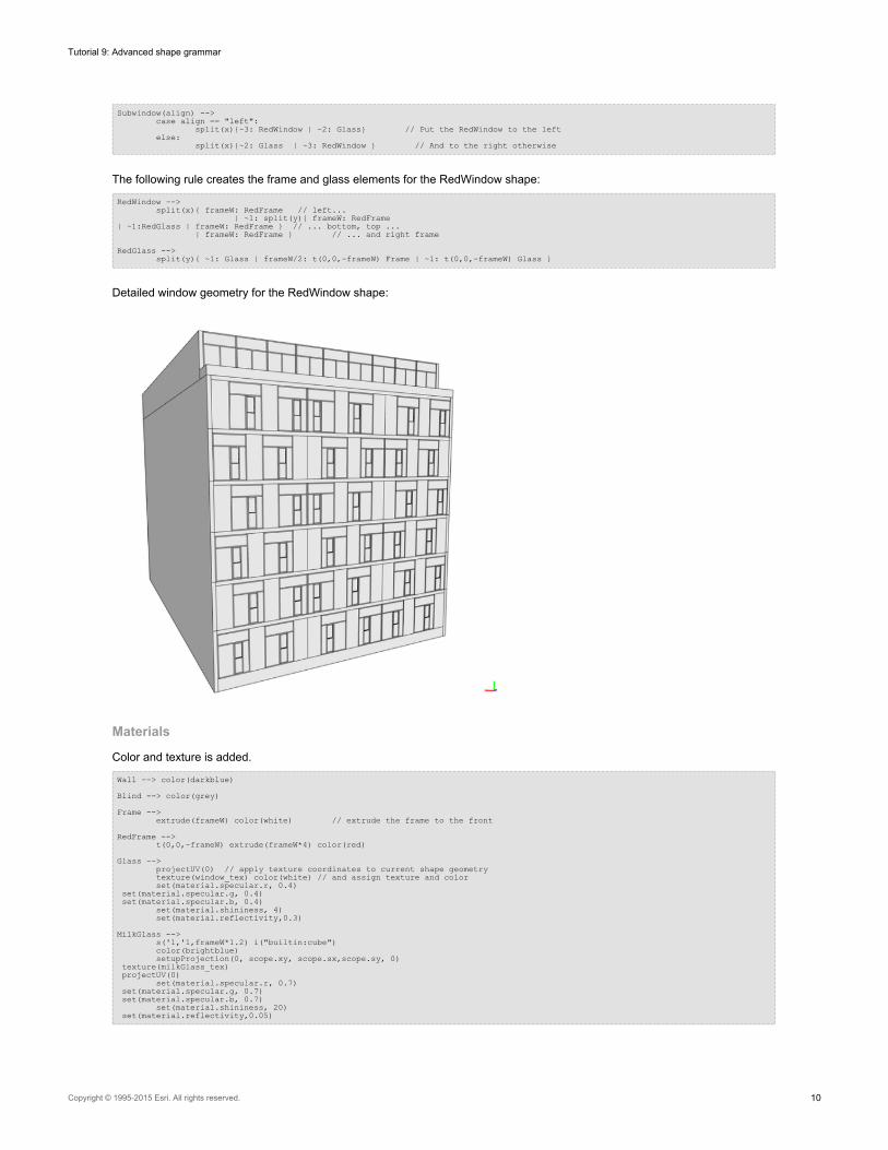
The following rule creates the frame and glass elements for the RedWindow shape:
RedWindow -->split(x){ frameW: RedFrame // left...
| ~1: split(y){ frameW: RedFrame| ~1:RedGlass | frameW: RedFrame } // ... bottom, top ...
| frameW: RedFrame } // ... and right frame
RedGlass -->split(y){ ~1: Glass | frameW/2: t(0,0,-frameW) Frame | ~1: t(0,0,-frameW) Glass }
Detailed window geometry for the RedWindow shape:
Materials
Color and texture is added.
Wall --> color(darkblue)
Blind --> color(grey)
Frame -->extrude(frameW) color(white) // extrude the frame to the front
RedFrame -->t(0,0,-frameW) extrude(frameW*4) color(red)
Glass -->projectUV(0) // apply texture coordinates to current shape geometrytexture(window_tex) color(white) // and assign texture and colorset(material.specular.r, 0.4)
set(material.specular.g, 0.4)set(material.specular.b, 0.4)
set(material.shininess, 4)set(material.reflectivity,0.3)
MilkGlass -->s('1,'1,frameW*1.2) i("builtin:cube")color(brightblue)setupProjection(0, scope.xy, scope.sx,scope.sy, 0)
texture(milkGlass_tex)projectUV(0)
set(material.specular.r, 0.7)set(material.specular.g, 0.7)set(material.specular.b, 0.7)
set(material.shininess, 20)set(material.reflectivity,0.05)
Tutorial 9: Advanced shape grammar
Copyright © 1995-2015 Esri. All rights reserved. 10
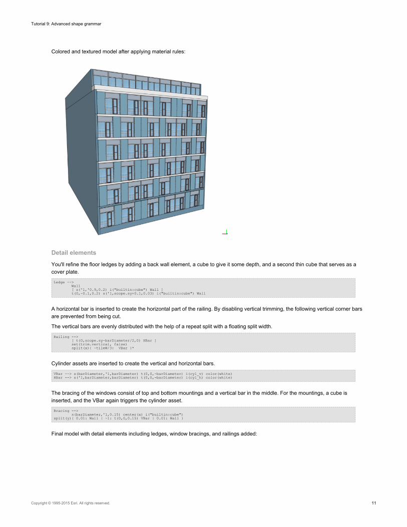
Colored and textured model after applying material rules:
Detail elements
You'll refine the floor ledges by adding a back wall element, a cube to give it some depth, and a second thin cube that serves as acover plate.
Ledge -->Wall[ s('1,'0.9,0.2) i("builtin:cube") Wall ]t(0,-0.1,0.2) s('1,scope.sy+0.1,0.03) i("builtin:cube") Wall
A horizontal bar is inserted to create the horizontal part of the railing. By disabling vertical trimming, the following vertical corner barsare prevented from being cut.
The vertical bars are evenly distributed with the help of a repeat split with a floating split width.
Railing -->[ t(0,scope.sy-barDiameter/2,0) HBar ]set(trim.vertical, false)split(x){ ~tileW/3: VBar }*
Cylinder assets are inserted to create the vertical and horizontal bars.
VBar --> s(barDiameter,'1,barDiameter) t(0,0,-barDiameter) i(cyl_v) color(white)HBar --> s('1,barDiameter,barDiameter) t(0,0,-barDiameter) i(cyl_h) color(white)
The bracing of the windows consist of top and bottom mountings and a vertical bar in the middle. For the mountings, a cube isinserted, and the VBar again triggers the cylinder asset.
Bracing -->s(barDiameter,'1,0.15) center(x) i("builtin:cube")
split(y){ 0.01: Wall | ~1: t(0,0,0.15) VBar | 0.01: Wall }
Final model with detail elements including ledges, window bracings, and railings added:
Tutorial 9: Advanced shape grammar
Copyright © 1995-2015 Esri. All rights reserved. 11

Now that you have the final model, go ahead and apply the rule on different lot shapes, or experiment with the user attributes in theInspector to modify your facade design.
Different styles
Using the style keyword, a new style is defined that redefines some attributes. In this case, you'll create a color variation by redefiningthe color attributes.
@Description("A Variation in Red")style Red_Color_Themeattr brightblue = "#FF8080"attr darkblue = "#D20000"attr grey = "#ECCACA"attr red = "#361B1B"
The Red_Color_Theme style applied:
Tutorial 9: Advanced shape grammar
Copyright © 1995-2015 Esri. All rights reserved. 12
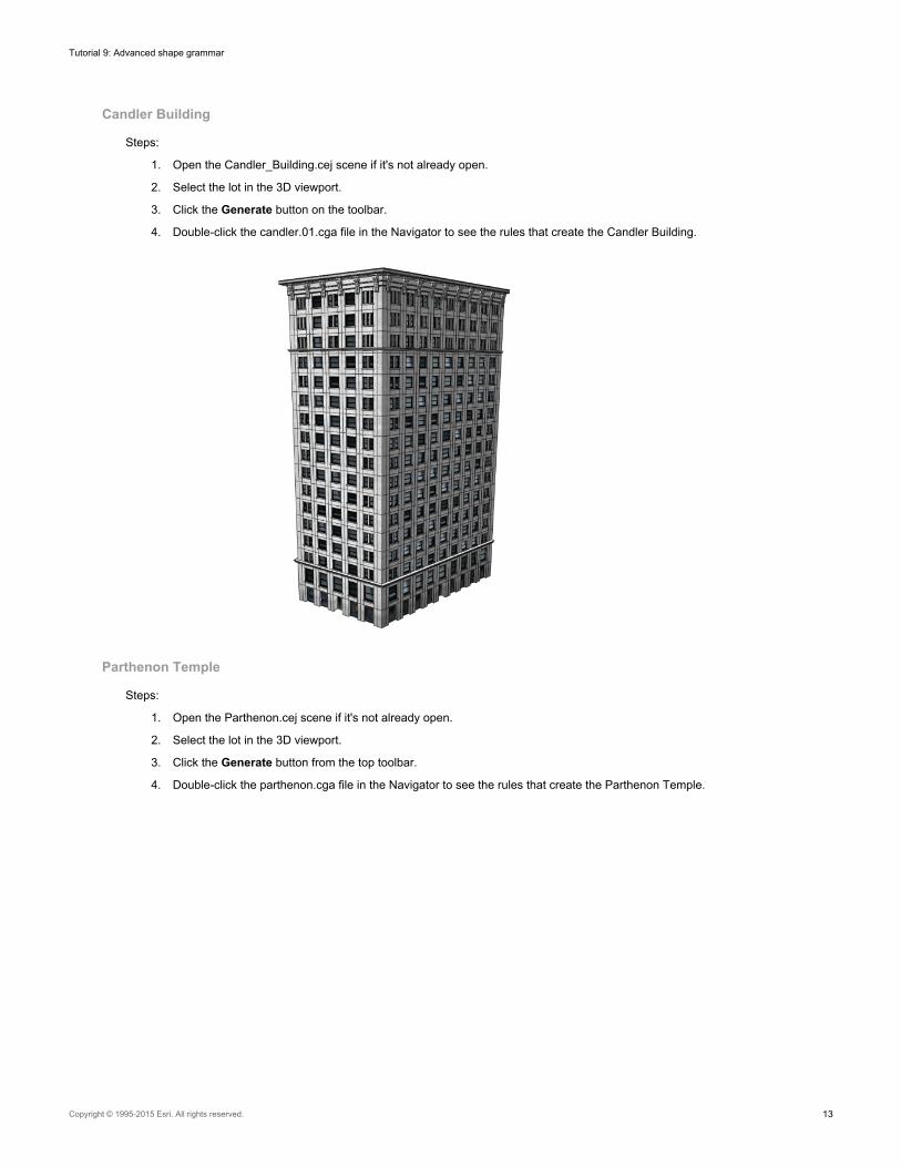
Candler Building
Steps:
1. Open the Candler_Building.cej scene if it's not already open.
2. Select the lot in the 3D viewport.
3. Click the Generate button on the toolbar.
4. Double-click the candler.01.cga file in the Navigator to see the rules that create the Candler Building.
Parthenon Temple
Steps:
1. Open the Parthenon.cej scene if it's not already open.
2. Select the lot in the 3D viewport.
3. Click the Generate button from the top toolbar.
4. Double-click the parthenon.cga file in the Navigator to see the rules that create the Parthenon Temple.
Tutorial 9: Advanced shape grammar
Copyright © 1995-2015 Esri. All rights reserved. 13