TurboVap 500 User's Manual
78
Copyright 2010, Biotage AB. All rights reserved. P/N C128100 Rev. 02 Closed Cell Concentrator TurboVap 500 User’s Manual
Transcript of TurboVap 500 User's Manual

Copyright 2010, Biotage AB. All rights reserved.P/N C128100 Rev. 02
Closed Cell Concentrator
TurboVap 500
User’s Manual


Preface 3
PrefaceCopyright
This manual is published by Biotage AB,10430 Harris Oaks Blvd. Suite C, Charlotte, NC 28269 U.S.A. Copyright 2010, Biotage AB. All rights reserved. Reproduction by any means or in any form of this manual or the products it describes is prohibited.
Trademarks
Biotage and TurboVap are trademarks of Biotage. Microsoft and Windows are either registered trademarks or trademarks of Microsoft Corporation in the United States and/or other countries. All other trademarks and registered trademarks are the property of their respective holders.
Content
The information in this manual may contain typographical errors or technical inaccuracies and is subject to change without notice. Modifications may also be made to the product described in this manual at any time.
Proper Equipment Operation
The TurboVap 500 Closed Cell Concentrator uses a patented gas vortex shearing technique to concentrate samples quickly. It is a microprocessor-controlled instrument for simultaneous, automated concentration of multiple samples with unattended operation, convenience, and speed. It is the customer’s responsibility to design suitable methods for evaporation of their own samples.
WARNINGS
• The TurboVap 500 is NOT designed for in vitro testing or for use with highly corrosive acids.
• To reduce the risk of electric shock, do not remove the cover. No user serviceable parts are inside. Refer to qualified service personnel if help is required.
• Use this product only in the manner described in this manual. If the equipment is used in a manner not specified by the manufacturer, the protection provided by the equipment may be impaired.
AVERTISSEMENTS
• Pour réduire le risque de choc électrique, ne pas retirer le couvercle. Ce produit ne contient aucune pièce pouvant être réparée par l’utilisateur. Au besoin, confier l’appareil à un réparateur qualifié.
• Ce produit ne doit être utilisé que comme décrit dans ce manuel. Si cet appareil est utilisé d’une manière autre que celle spécifiée par le fabricant, la protection fournie par l’appareil peut être entravée.
P/N C128100 Rev. 02 TurboVap 500 User’s Manual Biotage AB

Preface 4
Product Safety Warning
The TurboVap 500 power switch is the same type of power switch used on most laboratory equipment such as gas chromatographs, spectrophotometers, liquid chromatographs, and computers. The TurboVap products are safely used in the laboratory when “Good Laboratory Practices” are followed as with any other lab equipment. All fans are brushless motor fans and will not ignite vapors. The TurboVap is not classified as “Explosion Proof” and its use is at the discretion and risk of the operator or laboratory supervisor/manager. Your TurboVap product has been designed with safety as a foremost consideration. These products are equipped with a non-arcing fan, solid state electronics, and provisions for vapor collection. Do not change the configuration of the TurboVap 500 ventilation system. Please consult with Biotage if you have any questions or concerns regarding this subject.
WARNING
TurboVap products are NOT classified as “Explosion Proof.” The power switch is an arcing source and could ignite explosive vapors if present.
Contact Biotage 1-Point Support
Biotage 1-Point Support provides expert services including telephone troubleshooting of products, repair instructions, service dispatching and replacement part information.
Before you call:
Check the online Help and the manual for a probable cause and solution to your question.
Have the following information available for the customer support representative:
• Workstation serial number(s)
• If applicable, the error displayed on the LCD display
To reach the Biotage 1-Point Support:
US: 1-800-446-4752 or [email protected]
Europe and Asia-Pacific Regions: +46 18 56 57 11 or [email protected]
Japan: +81 422 28 1233 or [email protected]
Biotage Product Repair Depot
The Biotage Product Repair Depot offers product repair services, upgrades, refurbishment and installation at reasonable costs and with quick turnaround for all customer-owned equipment and accessories. For further information or to obtain a quotation for services, contact the Depot:
US: 1-800-446-4752 or [email protected]
Europe and Asia-Pacific Regions: +46 18 56 57 11 or [email protected]
Japan: +81 422 28 1233 or [email protected]
P/N C128100 Rev. 02 TurboVap 500 User’s Manual Biotage AB

Preface 5
Features of the Biotage Product Repair Depot:
• Factory-trained repair technicians
• Two week turnaround from receipt at Biotage
Shipping:
Customers are responsible for shipments both to and from Biotage, specifying the carrier and choice of service.
Return Policy:
To ensure a safe environment for all our technicians, it is mandatory for each returned product to include our chemical questionnaire stating contact chemicals, chemicals used during application and cleaning steps taken prior to shipment.
Processing:
Once the product is returned, it is evaluated for necessary repairs. The customer is contacted with an estimate and may choose to go ahead with the repair or decline service. If service is denied, a minimum evaluation charge may apply. Upon completion of the repair, a purchase order or appropriate means of payment is required before return shipment.
Service and Customer Support Plans
Biotage offers a full range of services to ensure your success. From our original factory warranty through a comprehensive line of customer support plans, Biotage AB offers you Field Service Engineers and In-house Specialists who are dedicated to supporting your hardware, software and application development needs.
US: 1-800-446-4752 or [email protected]
Europe and Asia-Pacific Regions: +46 18 56 57 11 or [email protected]
Japan: +81 422 28 1233 or [email protected]
Our programs can include such useful services as:
• preventative maintenance
• diagnostic servicing performed on-site by Biotage AB field service engineers
• extended use of the Biotage AB 1-Point Support Center
• automated, remote troubleshooting
• software updates
• after-hour, weekend and holiday support
• repair depot servicing
• parts, labor and travel expense coverage
• other customized services upon request
FCC
This device complies with part 15 of the FCC (United States Federal Communications Commission) Rules. Operation is subject to the following two conditions:
• This device may not cause harmful interference, and
• This device must accept any interference received, including interference that may cause undesired operation.
P/N C128100 Rev. 02 TurboVap 500 User’s Manual Biotage AB

Preface 6
CE
This device complies with all CE rules and requirements.
NOTE
Changes or modifications to this equipment not expressly approved by the party responsible for compliance could void the user’s authority to operate the equipment.
REMARQUE
Tout changement ou modification apporté à cet instrument non expressément approuvé par l’entité responsable de la conformité peut annuler l’autorisation d’opérer l’appareil accordée à l’utilisateur.
Table of Symbols
Table 1 contains symbols that identify particularly important information and alert you to the presence of hazards. These symbols may appear in this manual and/or on the product it describes.
Table 1. Important Symbols
SymbolSymbole
DescriptionDescription
DANGER: An imminently hazardous situation, which, if not avoided, will result in death or serious injury.
DANGER: Situation présentant un danger imminent qui, s’il n’est pas éliminé, peut entraîner des blessures graves, voire la mort.
WARNING: Caution, risk of danger. Refer to the User’s documentation.
AVERTISSEMENT: Attention, danger potentiel. Se reporter à la documentation de l’utilisateur.
NOTE: A cautionary statement; an operating tip or maintenance suggestion; may result in instrument damage if not followed.
REMARQUE: Énoncé indiquant une précaution à prendre, un conseil de fonctionnement ou une suggestion d’entretien; son non-respect peut provoquer des dommages à l’instrument.
Hazardous voltage; risk of shock injury.
Tension dangereuse; risque de blessure par électrocution.
Crush hazard. Risk of body parts, hair, jewelry, or clothing getting caught in a moving part.
Danger d’écrasement. Faire attention que les parties corporelles, les cheveux, les bijoux ou les vêtements ne soient pas pris dans une pièce mobile.
P/N C128100 Rev. 02 TurboVap 500 User’s Manual Biotage AB

Preface 7
Risk of puncture injury.
Risque de blessure par piqûre.
Risk of eye injury; wear safety glasses.
Risque de lésion oculaire; porter des lunettes de sécurité.
Risk of exposure to biohazards.
Risque d’exposition à biohazards.
Risk of fire.
Risque d’incendie.
Risk of poison.
Risque d’empoisonnement.
Risk of explosion.
Risque d’explosion.
Hazardous fumes.
Émanations dangereuses.
Hot surface; risk of burns.
Surface chaude; risque de brûlures.
Protective ground symbol.
Symbole de terre de protection.
Ground symbol.
Symbole de terre.
Fuse.
Fusible.
Alternating current.
Courant alternatif.
On (supply).
Marche (alimentation).
Off (supply).
Arrêt (alimentation).
CE compliance mark.
Marque de conformité CE.
Signifies that the unit has passed safety tests for grounding, power line transience, and current leakage.
Signifie que l’appareil a réussi les tests de sécurité pour la mise à la terre, le courant transitoire de ligne d’alimentation et la perte de courant.
Table 1. Important Symbols (Continued)
SymbolSymbole
DescriptionDescription
P/N C128100 Rev. 02 TurboVap 500 User’s Manual Biotage AB

Preface 8
Input.
Entrée.
Output.
Sortie.
Equipment labels are color coded:
Les étiquettes de l’appareil sont codées couleur:
Yellow Caution, risk of danger Red StopBlue Mandatory action Green Safe condition or information
Jaune Attention, danger potentielRouge ArrêterBleu Intervention obligatoireVert Condition sûre ou informations de sécurité
Helpful hints, additional information
Conseils utiles, informations supplémentaires
Table 1. Important Symbols (Continued)
SymbolSymbole
DescriptionDescription
P/N C128100 Rev. 02 TurboVap 500 User’s Manual Biotage AB

Table of Contents 9
Table of Contents
Preface .................................................................................................................... 3
Introduction .......................................................................................................... 12Gas Vortex Shearing Action .............................................................................. 12Automated Concentration .................................................................................. 13Sensors............................................................................................................. 13Adjustable ......................................................................................................... 13Convenience ..................................................................................................... 14Mild Conditions.................................................................................................. 14Multiple Sample Processing .............................................................................. 14Independent Operation...................................................................................... 14Requires No Hood............................................................................................. 14Vapor Removal ................................................................................................. 14
TurboVap 500 Hardware ....................................................................................... 15TurboVap 500 - Front ........................................................................................ 15TurboVap 500 - Rear......................................................................................... 16TurboVap 500 - Side ......................................................................................... 17Front Panel ....................................................................................................... 17
Concentrate Until Options ............................................................................ 18Cell Selections and Functions ...................................................................... 19Fan Speed Selections and Functions ........................................................... 19Closed Cell Parts and Functions .................................................................. 20
Installing the TurboVap 500 ................................................................................. 22Unpacking the TurboVap 500 ............................................................................ 22Parts Supplied................................................................................................... 22Other Required Items ........................................................................................ 23Tools Needed.................................................................................................... 23Site Preparation Requirements.......................................................................... 23Installing the TurboVap 500............................................................................... 25
Select the Location for the TurboVap 500 .................................................... 25Clean the Glassware.................................................................................... 25Remove the Sensors for Operation Above 60°C .......................................... 25Install the Motor Mounting Bracket............................................................... 25Assemble the Motor, Cell Cap, and Fan Blade ............................................. 26Add PTFE Sleeves to the Ground Glass Fittings .......................................... 28Assemble the Closed Cell Glassware .......................................................... 29Select an Appropriate Waste Container ....................................................... 30Connect the Drain (Solvent Reclamation) Tubing......................................... 30Connect the Coolant Tubing Lines ............................................................... 32Fill the Water Bath ....................................................................................... 34Connect the Power Cord.............................................................................. 34Turn ON the Power ...................................................................................... 34Power Up Diagnostics.................................................................................. 35
P/N C128100 Rev. 02 TurboVap 500 User’s Manual Biotage AB

Table of Contents 10
Determine Optimal Concentration Conditions .................................................... 36Water Bath Temperature Description ................................................................ 36
Water Bath Temperature Considerations ..................................................... 37Setting the Water Bath Temperature ............................................................ 37
Condenser Coolant Temperature Considerations .............................................. 37Fan Speed Considerations ................................................................................ 38
Selecting the Fan Speed.............................................................................. 38Selecting the Endpoint and Time Settings ......................................................... 39
When to Use Each Method .......................................................................... 39Set Time Expired - Concentrating for a Set Time ......................................... 40Sensor Endpoint - Concentrating Until the Sensor Detects the Endpoint ...... 40Set Time After Sensor - Concentrating for a Set Time Past Endpoint Detection41Stop Pressed - Concentrating Until the Start/Stop Button is Pressed ........... 41
General Guidelines For Achieving the Best Recoveries ..................................... 42Achieving Excellent Recoveries with 1.0mL Sample Stem Tubes ...................... 42Final Concentration Conditions Established for Your Sample ............................ 43
Operation .............................................................................................................. 44Preparing the Unit ............................................................................................. 44Adding the Sample and Assembling the Closed Cell ......................................... 45Starting the Concentration................................................................................. 45Stopping the Concentration ............................................................................... 46
When the Endpoint is Reached .................................................................... 46To Silence the Alarm ................................................................................... 46
Disassembling the Closed Cell .......................................................................... 46Removing the Sample from the Tube ................................................................ 47Turning the Power Off ....................................................................................... 47
Maintaining the TurboVap 500 ............................................................................. 48Daily Maintenance............................................................................................. 48Routine Maintenance ........................................................................................ 49
Other Preventative Maintenance .................................................................. 49Typical Yearly Consumables........................................................................ 49Sensors ....................................................................................................... 49
Water Bath Maintenance ................................................................................... 50Glassware Maintenance .................................................................................... 50
Methods of Cleaning the Glassware............................................................. 50Replacing the Fuses.......................................................................................... 52Cleaning the Water Bath ................................................................................... 53Refilling the Water Bath..................................................................................... 54Removing and Replacing the Sensors ............................................................... 54
Remove the Covers and Unplug the Connectors.......................................... 55Replace the Rack and Covers to Operate Without Sensors ......................... 56Operating Requirements When Sensors Are Removed ................................ 57Installing the Sensors .................................................................................. 57
Long Term Storage ........................................................................................... 58
Troubleshooting ................................................................................................... 59
P/N C128100 Rev. 02 TurboVap 500 User’s Manual Biotage AB

Table of Contents 11
Troubleshooting the Concentration Process ...................................................... 59Troubleshooting the Panel Display .................................................................... 61Troubleshooting the Unit ................................................................................... 62
Procedure for Dislodging Bubbles ................................................................ 63Software Diagnostics......................................................................................... 63
Power Up Diagnostics.................................................................................. 64Cell Diagnostics ........................................................................................... 65Motor Test Procedure .................................................................................. 67
Specifications ....................................................................................................... 68
Replacement Parts................................................................................................ 70TurboVap Units ................................................................................................. 70Accessories....................................................................................................... 70Glassware ......................................................................................................... 70Replacement Kits .............................................................................................. 71Spare Parts ....................................................................................................... 71Miscellaneous Items.......................................................................................... 72
Index ...................................................................................................................... 73
P/N C128100 Rev. 02 TurboVap 500 User’s Manual Biotage AB

Introduction 12
IntroductionThe Biotage TurboVap 500 Closed Cell Concentrator is a microprocessor-controlled concentrator that provides automated sample concentration using a helical gas flow and sensor endpoint detection technology.
Figure 1. The TurboVap 500
Gas Vortex Shearing ActionThe concentrator uses a patented gas vortex shearing action that maintains high concentration rates regardless of sample height in the tubes. A helical flow of air (see Figure 1) is created by a motor-driven fan. The helical flow sets up a vortexing action that promotes sample homogeneity and continuous rinsing of the tube wall. The solvent vapors rise, enter the condenser, condense on the side walls, and then run out the drain into a suitable waste or reclamation container.
P/N C128100 Rev. 02 TurboVap 500 User’s Manual Biotage AB

Introduction 13
Automated ConcentrationThe TurboVap 500 uses an integrated microprocessor to automatically time the concentration, control the water bath temperature, turn off the fans, and perform operational diagnostics.
SensorsOptical sensors in the water bath enable the TurboVap 500 to automatically stop the concentration when the sample level in the tube passes below the optical sensor. The final volume of the concentration, either 0.5 mL or 0.75 mL, depends on the size of the sample tube being used. The optical sensor tracks any slow changes in the optical density of the sample to assure that darkening or brightening samples do not stop the concentration prematurely. Once the sample passes below the optical sensor and remains below the sensor for a few seconds, the TurboVap 500 stops the concentration or starts the timer to concentrate for additional time.
The stem size of the concentrator tubes determines the final volume when using the sensor endpoint. Tubes with a 0.5 mL stem concentrate to 0.5 mL; tubes with a 1.0 mL stem concentrate to 0.75 mL and have a calibrated mark on the tube for you to reconstitute to 1.0 mL.
AdjustableThe TurboVap 500 enables you to:
• concentrate for a set time,
• use the sensor endpoint to detect a level of 0.5 mL or 0.75 mL,
• continue concentrating for a set time after reaching the sensor endpoint,
• concentrate until stopped manually,
• optimize the concentration rate by adjusting the water bath temperature and the fan speed.
NOTE
• Time, temperature, and fan speed may be changed at any time.
P/N C128100 Rev. 02 TurboVap 500 User’s Manual Biotage AB

Introduction 14
ConvenienceThe TurboVap 500 enables you to start a run of samples and leave the instrument unattended. When the concentration has finished, the fans turn off automatically and the concentrator sounds an alarm every 30 seconds until the samples are removed or Start/Stop is pressed.
Mild ConditionsThe water bath provides sufficient warming without harming sample recovery.
Multiple Sample ProcessingThe concentrator has two tube positions. This allows either one or two samples to be processed simultaneously.
Independent OperationConcentration for each cell can be independently started or stopped at any time.
Requires No HoodThe vent tubing permits the unit to be placed on the bench rather than taking up valuable hood space.
Vapor RemovalThe solvent vapors are removed by the fans through the Vent tubing. The vent tubing must be routed to a suitable outside ventilation system.
P/N C128100 Rev. 02 TurboVap 500 User’s Manual Biotage AB

TurboVap 500 Hardware 15
TurboVap 500 Hardware
TurboVap 500 - Front
Figure 2. TurboVap 500 Parts
Mounting Bracket
Holds the motor assembly when not in use.
Front Panel
Controls the setup and operation of the concentrator. See “Front Panel” on page 17 for details.
Power Switch
Turns the power ON or OFF.
WARNING
The power switch is an arcing source and could ignite excessive explosive vapors if present. DO NOT change the position of the unit’s on/off power switch when explosive vapors are present.
Condenser Holding Cups
Hold the condensers when not is use.
Water Bath
Warms the sample tubes during concentrations.
WARNING
Fire and burn hazard. Do NOT operate the TurboVap 500 without water in the water bath.
Mounting Bracket
Front Panel
PowerSwitch
CondenserHolding Cups
Inlet andOutlet
WaterBath
P/N C128100 Rev. 02 TurboVap 500 User’s Manual Biotage AB

TurboVap 500 Hardware 16
TurboVap 500 - Rear
Figure 3. TurboVap 500 Hardware, Rear View
Fan
Cools the internal components. Do not block the fan opening.
Alarm Volume Control
Adjusts the loudness of the buzzer that signals when the endpoint is reached or a button is pressed.
Power Entry Port
Supplies power to the unit and houses the fuses.
WARNING
• To avoid the risk of fire or electrical shock, plug the power cord securely into a properly grounded outlet.
• Replace fuses ONLY with the same type and rating.
Service Panel
Provides access to the motor and sensor connectors.
WARNING
To avoid electrical shock and other injuries, turn OFF the power and unplug the power cord before removing the service panel.
Fan
AlarmVolumeControl
Power EntryPort
ServicePanel
P/N C128100 Rev. 02 TurboVap 500 User’s Manual Biotage AB
TurboVap 500 Hardware 17
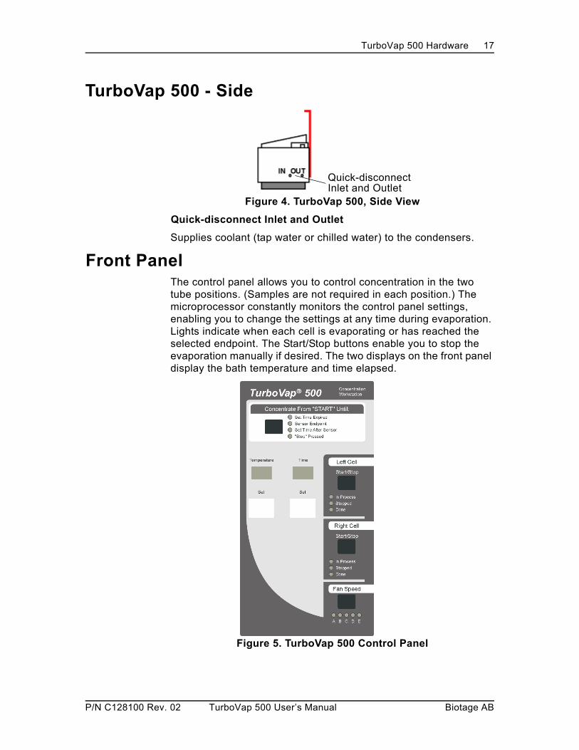
TurboVap 500 - Side
Figure 4. TurboVap 500, Side View
Quick-disconnect Inlet and Outlet
Supplies coolant (tap water or chilled water) to the condensers.
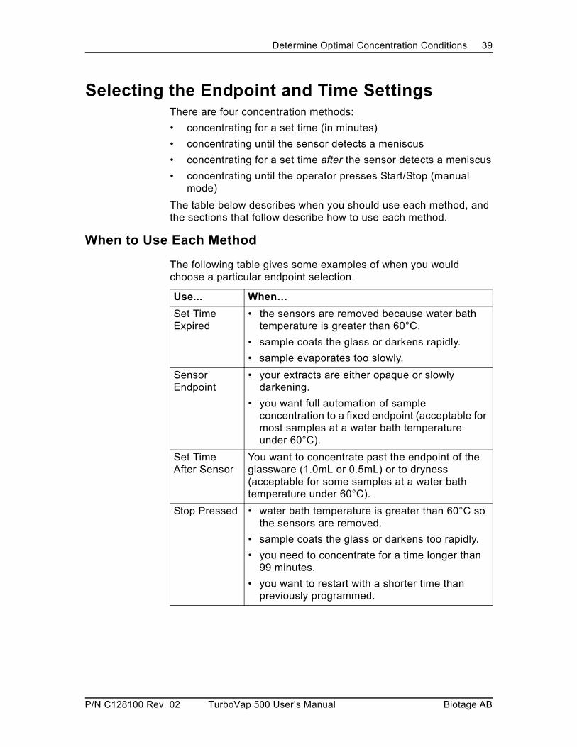
Front PanelThe control panel allows you to control concentration in the two tube positions. (Samples are not required in each position.) The microprocessor constantly monitors the control panel settings, enabling you to change the settings at any time during evaporation. Lights indicate when each cell is evaporating or has reached the selected endpoint. The Start/Stop buttons enable you to stop the evaporation manually if desired. The two displays on the front panel display the bath temperature and time elapsed.
Figure 5. TurboVap 500 Control Panel
Quick-disconnectInlet and Outlet
P/N C128100 Rev. 02 TurboVap 500 User’s Manual Biotage AB

TurboVap 500 Hardware 18
Concentrate Until Options
Concentrate Until Button
Used to select the desired endpoint for the concentration:
• Set Time Expired - to concentrate for the period of time in minutes specified by the Time setting on the panel
• Sensor Endpoint - to concentrate until the sensor detects a level of 0.5 or 1.0mL (depending upon the style of concentrator tube)
• Set Time After Sensor - to concentrate past the 0.5mL or 1.0mL setting by the amount of time in minutes specified by the Time setting
• Stop Pressed - to concentrate until the operator presses the Start/stop button for the individual cell (Manual operation)
Temperature Pushwheel
Sets the desired water bath temperature in degrees Centigrade.
WARNING
DO NOT operate at temperatures greater than 60°C with the sensors in place. See “Removing and Replacing the Sensors” on page 54 for operation at temperatures above 60°C.
Temperature Display
Displays the actual water bath temperature.
NOTE: The display blinks if the actual water bath temperature is 2 or more degrees different than the set temperature.
WARNING
To avoid the risk of fire or burn injuries, do NOT operate the TurboVap 500 without water in the bath.
Time Pushwheel
Sets the desired time in minutes (total concentration time or additional time after sensor endpoint detection).
Time Display
Displays the time elapsed. The display indicates the left or right cell by flashing “L=” or “r=” before the time elapsed display. “SE” is displayed if sensor detection is being used.
P/N C128100 Rev. 02 TurboVap 500 User’s Manual Biotage AB

TurboVap 500 Hardware 19
Cell Selections and Functions
Fan Speed Selections and Functions
WARNING
Always keep body parts, hair, jewelry, and clothing away from the fans.
Note: The fan speed button is also used to run diagnostics (see “Software Diagnostics” on page 63).
Cell Button and Lights Function
Start/Stop Button Used to start or stop concentration for each cell.
In Process Light On when the cell is performing concentration.
Stopped Light On when the Start/Stop button is pressed during concentration.
Done Light On when the cell has reached its endpoint.
Fan Speed Selection Function
A through E to set the speed of the cell cap fans.A = 4000 rpmB = 5000 rpmC = 6000 rpmD = 7000 rpmE = 8000 rpm
P/N C128100 Rev. 02 TurboVap 500 User’s Manual Biotage AB

TurboVap 500 Hardware 20
Closed Cell Parts and Functions
Figure 6. Closed Cell Glassware
Motor Assembly
Holds the motor that drives the fan blades.
Cell Cap
Encloses the fan blade.
WARNING
Always keep body parts, hair, jewelry and clothing away from the fan blades.
Motor Assembly
Cell Cap
Fan Blade
Coolant Outlet
Coolant Inlet
Reclaimed SolventDrain
Concentrator Tube
Condenser
P/N C128100 Rev. 02 TurboVap 500 User’s Manual Biotage AB

TurboVap 500 Hardware 21
Condenser
Condenses and reclaims the solvent. Includes an inlet and outlet for the coolant (tap or chilled water) and a drain for the reclaimed solvent.
WARNING
The liquid exiting the solvent drains may be corrosive, flammable and/or toxic. Refer to the MSDS (Material Safety Data Sheet) for detailed information.
• Do not touch drainage.
• Keep drainage from heat or flame.
• Dispose of drainage and container properly.
• Avoid direct contact with this liquid.
• Periodically check drainage tubes for damage.
• Make sure drain flow is not inhibited.
• Only use waste containers large enough to hold the drainage.
Concentrator Tube (Sample Tube)
Contains the sample to be concentrated. Sample tubes for endpoint detection at either 1.0mL or 0.5mL are available.
P/N C128100 Rev. 02 TurboVap 500 User’s Manual Biotage AB

Installing the TurboVap 500 22
Installing the TurboVap 500
Unpacking the TurboVap 500Unpack the shipping container and verify that all items listed below are present. If anything is damaged or missing, contact the Biotage 1-Point Support Center (see page 4).
Parts SuppliedThe Biotage TurboVap 500 Closed Cell Concentrator comes with the following parts:
• Concentrator Unit
• two Motor Assemblies
• Motor Mounting Bracket Kit
— Bracket
— two Post Covers
— four screws
• Glassware in boxes
— two Condensers
— two Cell Caps
— two Sample Tubes with 1.0mL stems
• PTFE Sleeve Kit
— Sleeve Installation Tool
— four PTFE Sleeves
• Fan Blade Kit
— two Fan Blade Assemblies
— two sets of PTFE Seals (2 large and 2 small seals)
— Allen Wrench, 0.050"
• two Drain Tubing Kits, each containing
— Drain Tubing assembly with two different tubings
— 1/8” I.D. Bevaline V tubings, 5 feet, for vent line
— two Tubing Clips
— Waste Cap with U.S. 38-430 threads
— Cap Insert
— Insert Modifier (optional use)
— Vent Line Restrictors
— Instructions
P/N C128100 Rev. 02 TurboVap 500 User’s Manual Biotage AB

Installing the TurboVap 500 23
Parts Supplied (Continued)
• Condenser Cooling Tubing Kit— four Condenser coolant line tubing lengths with screw-on
cap and Quick-disconnect fitting— two Quick-disconnect fittings, 1/4” barb, for Coolant
Supply tubing— 15 ft. 1/4” ID tubing for Coolant Supply— Instructions
• Clear Bath Kit
• two plastic Water Bath Covers
• Power Cord(s) - 220V models include two power cords, one for EU and one for UK
• Auxiliary Rack
• Siphon
• Spare seals
• Reference Card and Solvent Warning Sheet
• User’s Manual CD
Other Required Items• Condenser coolant supply (the chiller) or cold tap water
Tools NeededTo install the concentrator, you will need
• Flatblade screwdriver
• Wire cutters or scissors.
Site Preparation RequirementsYou must have an appropriate location with power and water sources available as specified by these site preparation requirements before installing the TurboVap 500 Closed Cell Concentrator.
Space
Dimensions of the concentrator:
• Height: 24 inches (60.9 cm)
• Width: 21.2 inches (53.8 cm)
• Depth: 12 inches (31 cm)
• Weight: 40.5 lbs (18.5 Kg) with the water bath empty
P/N C128100 Rev. 02 TurboVap 500 User’s Manual Biotage AB

Installing the TurboVap 500 24
Work Area:
Flat, level, stable surface
Power:
Fuses:
Condenser Water Supply:
• 1/4” ID supply
• 1/4” ID drain
• Tap water or chilled water without antifreeze
Chiller (if used):
• Chiller must be able to absorb approximately 60 watts/sample.
Bath Capacity:
• 6.4L maximum distilled water. DO NOT overfill.
WARNING
Burn hazard. DO NOT move the unit when the bath is full.
Clear Bath Additive:
2 oz. kit supplied with unit
WARNING
Exposure to liquids may cause bacterial or viral hazards. Liquids can also be corrosive, flammable and/or toxic. Use good laboratory operating procedures when dealing with liquids. Refer to the MSDS (Material Safety Data Sheet) for detailed information.
• Avoid direct contact with liquids.
• Wear protective gloves and safety glasses.
• Dispose of liquids and containers properly.
• Do not overfill containers.
100/120VAC model 220/240 VAC model
100/120VAC +/- 10% 220/240 VAC +/- 10%
50 - 60 Hz 50 - 60 Hz
100/120VAC model 220/240 VAC model
(1) 10A, T250V (P/N C39164) (2) 5A, T250V (P/N C44412)
P/N C128100 Rev. 02 TurboVap 500 User’s Manual Biotage AB

Installing the TurboVap 500 25
Installing the TurboVap 500
Select the Location for the TurboVap 500
Select a flat, stable, dry bench location within reach of the required power and water sources.
Clean the Glassware
Ensure that the TurboVap 500 closed cell concentrator glassware is clean, according to your standard laboratory practices. “Methods of Cleaning the Glassware” on page 50 describes some common cleaning methods.
Remove the Sensors for Operation Above 60C
If you will be operating the TurboVap 500 at water bath temperatures above 60°C, you must remove the sensors. See “Removing and Replacing the Sensors” on page 54 for detailed instructions on removing the sensors.
Install the Motor Mounting Bracket
Tools and parts required:
• flatblade screwdriver
• four screws
• motor mounting bracket
• two post covers
Figure 7. Motor Bracket Parts
To install the motor mounting bracket:
1 Position the mounting bracket against the back of the concentrator with the two cutouts in the top of the bracket toward the front of the concentrator. Line up the two holes on each bracket post with the two holes on each side of the rear service panel as shown in Figure 8 on page 26.
P/N C128100 Rev. 02 TurboVap 500 User’s Manual Biotage AB

Installing the TurboVap 500 26
Install the Motor Mounting Bracket (Continued)
Figure 8. Mounting Bracket Position, Back of TurboVap
2 Using a flatblade screwdriver, secure the mounting bracket with the screws provided.
3 Place the two motor assemblies onto the top of the mounting bracket.
4 Thread the motor wires into the channels on the mounting bracket posts.
5 Snap the post covers in place over each channel, lining up the dimples with the holes in the channel.
Assemble the Motor, Cell Cap, and Fan Blade
Tools and parts required:
• 0.05” Allen wrench (supplied)
• small and large PTFE seals
• fan blades
• two glass cell caps
• two motors
Figure 9. Fan Blade Parts and Glass Cell Caps
MountingBracketPost
ServicePanel
P/N C128100 Rev. 02 TurboVap 500 User’s Manual Biotage AB

Installing the TurboVap 500 27
Assemble the Motor, Cell Cap, and Fan Blade (Continued)
1 Insert the small PTFE seals into the cavities of the larger white PTFE seals as shown in Figure 10.
Figure 10. Assembling the PTFE Seals
2 Place the two seals into the top of each glass cell cap as shown in Figure 11.
Figure 11. Placing the PTFE Seals
NOTE
You must remove these seals before you bake the glass cell caps.
3 Loosely screw the cell cap and seals into the motor assembly.
4 Install the fan blade into the motor assembly:
a Align the flat on the fan blade with the set screws in the motor coupling as shown in Figure 12.
Figure 12. Installing the Fan Blade
b Tighten the set screw with the 0.05” Allen wrench (supplied).
Inner Seal
Outer Seal
Seals
Glass Cell Cap
P/N C128100 Rev. 02 TurboVap 500 User’s Manual Biotage AB

Installing the TurboVap 500 28
Add PTFE Sleeves to the Ground Glass Fittings
The TurboVap 500 comes with four PTFE sleeves and a sleeve installation tool. The sleeves are placed on the ground-glass ends of the Cell Caps and the condensers. The sleeves (shown in Figure 13) eliminate vapor leaks, providing a better seal during concentrations. The sleeves also allow easier separation of the glassware.
Figure 13. PTFE Sleeves
NOTE
You must remove the sleeves before you bake the glassware.
1 Place the lower end of a cell cap onto the lip of the installation tool.
2 Starting with the wider opening of the PTFE sleeve, place the sleeve onto the tool as shown in Figure 14.
Figure 14. Installing the PTFE Sleeves
3 Pull the sleeve along the tool until it fits onto the cell cap. Remove the tool.
4 Repeat this procedure to add a sleeve onto the other cell cap and onto both condensers as shown in Figure 15 on page 29.
Cell Cap
Ground Glass Joint
Installation Tool
PTFE Sleeve
P/N C128100 Rev. 02 TurboVap 500 User’s Manual Biotage AB

Installing the TurboVap 500 29
Add PTFE Sleeves to the Ground Glass Fittings (Continued)
Figure 15. PTFE Sleeve on Condenser
Assemble the Closed Cell Glassware
Assemble the glassware as shown in Figure 16 and place the assemblies into the water bath racks.
Figure 16. Assembled Closed Cell Glassware
Condenser
Ground Glass Joint
PTFE Sleeve
Motor Assembly
Cell Cap
Fan Blade
Coolant Outlet
Coolant Inlet
Reclaimed SolventDrain
Concentrator Tube
Condenser
P/N C128100 Rev. 02 TurboVap 500 User’s Manual Biotage AB

Installing the TurboVap 500 30
Select an Appropriate Waste ContainerConsider the following recommendations when selecting a waste container for each condenser:
• A 4 L solvent bottle, placed on the floor is an ideal waste container.
NOTE: Follow an appropriate chemical hygiene plan for your laboratory; a second overflow waste container may be required.
• Use a waste container with a standard U.S. 38-430 thread pattern. (A cap insert modifier is included for use with European 38-430 bottles)
• Select a container that will allow a gravity-feed fluid flow down the tube.
• Select at least a 500mL container. The waste container must hold at least the total amount of evaporating solvent plus an additional 100 mL.
Connect the Drain (Solvent Reclamation) TubingThe contents of the Drain Tubing Kit are shown in Figure 17:
Figure 17. Drain Tubing Kit
To connect the drain tubing:
1 Select a Solvent Reclamation/Waste Container for each condenser. Place the containers below the condensers.
2 With the condensers and concentrator tubes assembled and in place in the water bath racks, attach the screw-on fitting end of the drain tubing line assembly to the reclaimed solvent drain fitting (the lowest fitting on the condenser).
3 Route the drain lines to the waste containers and secure the tubing to the rear panel of the unit:
a Slide the tubing clips onto the drain tubing.
P/N C128100 Rev. 02 TurboVap 500 User’s Manual Biotage AB

Installing the TurboVap 500 31
Connect the Drain (Solvent Reclamation) Tubing (Continued)b Fasten the clips to the service panel using the lower-left and
lower-center service panel screws as shown in Figure 18.
Figure 18. Tubing Clips
4 Place the cap insert into the supplied plastic cap (see Figure 19), screw the cap onto the waste container and attach the drain tubing to the large barb fitting.
Figure 19. Cap Insert
5 Connect the small ID vent tubing to the small barb on the cap insert.
6 Insert the vent line restrictor into the open end of the vent tubing and route the vent tubing line to a hood or outside ventilation source.
Figure 20. Vent Line Restrictor
7 If the cap and insert don’t fit tightly onto the waste container, add the insert modifier to the cap insert.
TubingClips
Cap
Cap Insert
Drain Line fromCondenser
Vent Line Restrictor
Vent Line withRestrictor
P/N C128100 Rev. 02 TurboVap 500 User’s Manual Biotage AB

Installing the TurboVap 500 32
Connect the Coolant Tubing LinesThe coolant system assembly requires twelve tubing line connections. (Note: Consult the instructions for your chiller as required.)
Use the four tubing assemblies to make the connections between the TurboVap 500 condenser’s coolant inlet and outlets and the unit’s coolant IN and OUT connections.
Use the 15’ length of supplied ¼” I.D. tubing and two ¼” barb quick-disconnect fittings to connect the TurboVap 500 to the external coolant supply (not supplied).
1 Connect the TurboVap 500 to the external coolant supply:
Figure 21. Coolant Tubing
a Cut the 15’ ¼” I.D. tubing in half.
b Attach one ¼” barb quick-disconnect fitting to one end of each tubing length.
Figure 22. Coolant Line Fitting
2 Insert the barbed fitting on one of the lengths of tubing into the TurboVap 500 coolant supply INLET port on the side of the TurboVap 500, and connect the other end to the external coolant supply OUT.
Figure 23. Coolant Supply Out Connection
to Coolant Supply OUT
P/N C128100 Rev. 02 TurboVap 500 User’s Manual Biotage AB

Installing the TurboVap 500 33
Connect the Coolant Tubing Lines (Continued)
3 Insert the barbed fitting on the other length of tubing into the TurboVap 500 coolant supply OUT port on the side of the TurboVap 500, and connect the other end to the external coolant supply RETURN.
Figure 24. Coolant Supply Return Connection
4 Connect the condensers to the unit’s coolant IN and OUT ports on the top of the TurboVap 500:
Figure 25. Condenser Tubing
a Connect the screw-on caps on the tubing to the condenser IN and OUT fittings.
b Attach the top condenser fitting (coolant OUT) to the TurboVap 500 OUT and the lower condenser fitting (coolant IN) to the TurboVap 500 IN as shown in Figure 26.
c Place the condensers on the resting blocks. Place the concentrator tubes into the Auxiliary Rack.
Figure 26. Condenser Connections, viewed from the back
to Coolant Supply RETURN
P/N C128100 Rev. 02 TurboVap 500 User’s Manual Biotage AB

Installing the TurboVap 500 34
Fill the Water Bath
When filling the water bath, make sure that:
• the level of water in the bath is as high as the initial solvent level in the sample tube.
• placing the sample tubes in the water bath does not cause an overflow.
To fill the water bath:
1 Pour about 1 Liter of distilled water into the bath.
2 Add 15 drops of Clear Bath additive.
3 Add distilled water until the water is at the recommended height.
WARNING
Fire and burn hazard. Do not operate the TurboVap 500 without water in the bath.
4 Place the plastic water bath covers over both of the water bath positions.
Connect the Power Cord
1 Plug the power cord securely into the receptacle on the back of the unit. Make sure the plug is fully inserted.
2 Connect the 3-pronged end to an appropriate power source.
WARNING
To avoid the risk of fire or electrical shock, plug the power cord into a properly grounded outlet.
Turn ON the Power
To turn on the concentrator, turn ON the switch located on the lower left side of the TurboVap. When the power is turned on, the Power-Up diagnostics described below will run automatically.
Note: Upon power up, the Start/Stop button for the six cells will not work until an endpoint and fan speed have been selected.
P/N C128100 Rev. 02 TurboVap 500 User’s Manual Biotage AB

Installing the TurboVap 500 35
Power Up Diagnostics
When power is first turned on, the following diagnostics occur:
Display Test - During the first four seconds after power up, all display lights are lit. Confirm that no lights are out.
Normal operation begins after four seconds. (See “Software Diagnostics” on page 63 for other Power-Up diagnostics.)
P/N C128100 Rev. 02 TurboVap 500 User’s Manual Biotage AB

Determine Optimal Concentration Conditions 36
Determine Optimal Concentration ConditionsYou should determine the settings that will best concentrate your samples before operation. You should determine the best:
• water bath temperature
• condenser coolant temperature
• fan speed
• endpoint selection
Set up a concentrator tube with the typical volume of sample or solvent and some analytes of interest. Then experiment with the various selections. The more efficient the concentration, the better the analyte recoveries. Optimizing the water bath and coolant temperatures, the endpoint and fan speed will yield the best results when using the TurboVap 500 unit.
To prepare the TurboVap 500:
1 Turn the evaporator’s power ON.
NOTE: The unit should always be ON whenever it contains samples so that the fan can remove exhaust.
2 Remove all tubes from the evaporator.
Water Bath Temperature DescriptionConcentrator tubes are placed in one of two positions in the temperature-controlled water bath. Since the concentrator's high concentration rates eliminate the need for a high temperature water bath, the bath operates over a mild temperature range of ambient to 90C. This eliminates “hot” spots and improves sample recovery for more volatile compounds. The water bath also can be brought down below room temperature by using evaporative cooling. Cooling ability varies with the concentration rate.
WARNING
To avoid the risk of fire or burn injuries, do NOT operate the TurboVap 500 without water in the bath.
P/N C128100 Rev. 02 TurboVap 500 User’s Manual Biotage AB

Determine Optimal Concentration Conditions 37
Water Bath Temperature Considerations
When selecting the water bath temperature, consider the following:
• Faster evaporation occurs as the water bath temperature is increased. However, highly volatile analytes can be lost if allowed to sit for extended periods of time in a warm bath.
• You can select a water bath temperature just below the boiling point of the solvent in the sample tube. Ensure that the sample, especially in the stem, will not boil. Boiling the solvent affects sensor operation and can risk loss of sample.
• A temperature setting of “00” turns off the heaters.
Setting the Water Bath Temperature
1 Set the water bath temperature using the numeric pushwheel.
2 Place a plastic cover over any empty water bath position.
3 Allow the bath to come to temperature (the display stops blinking) before using the concentrator.
NOTE
As the bath warms up, bubbles may form around the sensor. If given enough time (approximately 1/2 hr.), bubbles should dissipate. In most cases, sample tube insertion will free bubbles.
Condenser Coolant Temperature ConsiderationsCoolant supply to the condenser may be either cold tap water or water that is supplied by a chiller. When selecting the coolant supply and temperature, consider the following:
• the condenser coolant temperature affects the evaporation rate.
• coolant water should NOT contain antifreeze.
• a stable system, without temperature fluctuations, is necessary to prevent freezing at the lowest coolant temperatures.
NOTE
Coolant temperature should always be greater than 4°C to avoid the possibility of FREEZING the coolant.
P/N C128100 Rev. 02 TurboVap 500 User’s Manual Biotage AB

Determine Optimal Concentration Conditions 38
Fan Speed ConsiderationsWhen selecting the fan speed, consider the following:
• higher fan speed causes faster evaporation rates.
• excessively high speed can cause loss of analyte due to splashing.
• for semi-volatile analytes, best recoveries have been obtained at the lower fan speeds A or B (4000 to 5000 rpm).
Selecting the Fan Speed
To establish the optimal fan speed setting, run test samples at various speeds and compare the analyte recoveries. Choose the fan speed that gives the best analyte recoveries.
Press the Fan Speed button until the light for the desired speed is lit; each press advances to the next speed.While the button is depressed, the selection's speed appears in the Temperature and Time displays.
The displays return to normal when the button is released.
Selection Fan Speed (rpm)
A 4000
B 5000
C 6000
D 7000
E 8000
P/N C128100 Rev. 02 TurboVap 500 User’s Manual Biotage AB
Determine Optimal Concentration Conditions 39
Selecting the Endpoint and Time SettingsThere are four concentration methods:
• concentrating for a set time (in minutes)
• concentrating until the sensor detects a meniscus
• concentrating for a set time after the sensor detects a meniscus
• concentrating until the operator presses Start/Stop (manual mode)
The table below describes when you should use each method, and the sections that follow describe how to use each method.
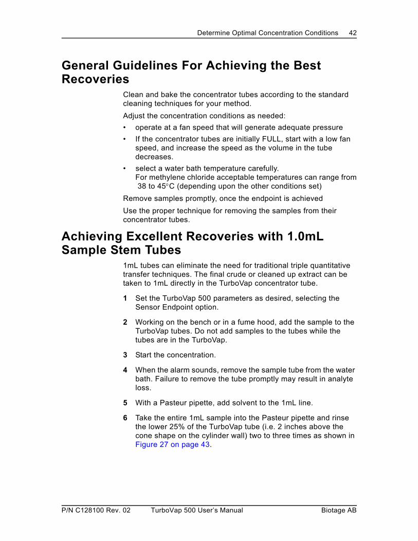
When to Use Each Method
The following table gives some examples of when you would choose a particular endpoint selection.
Use... When…
Set Time Expired
• the sensors are removed because water bath temperature is greater than 60°C.
• sample coats the glass or darkens rapidly.
• sample evaporates too slowly.
Sensor Endpoint
• your extracts are either opaque or slowly darkening.
• you want full automation of sample concentration to a fixed endpoint (acceptable for most samples at a water bath temperature under 60°C).
Set Time After Sensor
You want to concentrate past the endpoint of the glassware (1.0mL or 0.5mL) or to dryness (acceptable for some samples at a water bath temperature under 60°C).
Stop Pressed • water bath temperature is greater than 60°C so the sensors are removed.
• sample coats the glass or darkens too rapidly.
• you need to concentrate for a time longer than 99 minutes.
• you want to restart with a shorter time than previously programmed.
P/N C128100 Rev. 02 TurboVap 500 User’s Manual Biotage AB

Determine Optimal Concentration Conditions 40
Set Time Expired - Concentrating for a Set Time
To concentrate for an exact length of time, use the Set Time Expired option:
1 Press the Concentrate Until button until Set Time Expired is selected.
2 Use the Set Time buttons to select the desired time, in minutes, for concentration.
3 Press the Start/Stop button for the cell position(s).
Reading the Time Display during a Timed Concentration
The Time display shows the actual elapsed time alternately for each cell. “L=” precedes the left cell value, and “r=” precedes the right cell value.
Sensor Endpoint - Concentrating Until the Sensor Detects the Endpoint
To use the optical sensors to concentrate to a volume of either 1.0mL or 0.5mL, select the Sensor Endpoint option. The volume at which concentration stops depends on the stem length of the concentrator tube. To set up a Sensor Endpoint concentration:
1 Press the Concentrate Until button until Sensor Endpoint is selected.
2 Press the Start/Stop button for the cell position(s).
Reading the Time Display during a Sensor Endpoint Concentration
The Time display shows “SE”
Sensor Endpoint Considerations
Two conditions affect optical sensing:
1 Water Bath TemperatureRemove the sensors if the water bath temperature is set above 60°C. (See page 54 for detailed instructions.)
2 Sample Clarity - Clear, slowly darkening, or opaque (at 940 nm) samples reliably operate when using the endpoint detector. Samples which darken too rapidly as concentration proceeds may activate the sensor prematurely. If this happens, press the Start/Stop button for the sensor to start with a new baseline reading and continue concentration.
P/N C128100 Rev. 02 TurboVap 500 User’s Manual Biotage AB

Determine Optimal Concentration Conditions 41
If starting a new baseline is unacceptable, determine concentration time and use the Set Time Expired option, or operate manually by using the Stop Pressed selection.
Set Time After Sensor - Concentrating for a Set Time Past Endpoint Detection
To continue concentration after the sensor detects a 0.5mL or 1.0mL endpoint (depending on glassware), select the Set Time After Sensor option. To set up a Set Time After Sensor concentration:
1 Press the Concentrate Until button until Set Time After Sensor is selected.
2 Use the Set Time buttons to set the desired time, in minutes, for concentration to continue after endpoint detection.
3 Press the Start/Stop button for the cell position(s).
Reading the Time Display during a Set Time After Sensor Concentration
The Time display shows “SE” until the endpoint is reached. Once the endpoint is reached, the actual elapsed time after the endpoint is displayed for each cell.
Set Time After Sensor Endpoint Considerations
The same considerations exist for this selection as for the Sensor Endpoint selection. See “Sensor Endpoint Considerations” on page 40.
Stop Pressed - Concentrating Until the Start/Stop Button is Pressed
To operate the TurboVap 500 manually, use the Stop Pressed option. To set up a Stop Pressed concentration:
1 Press the Concentrate Until button until Stop Pressed is selected.
2 Press the Start/Stop button for the cell position(s).
Reading the Time Display during a Stop Pressed Concentration
The Time display shows the actual elapsed time alternately for each cell. “L=” precedes the left cell value, and “r=” precedes the right cell value.
If the elapsed time exceeds 99 minutes, the number display is replaced with .
P/N C128100 Rev. 02 TurboVap 500 User’s Manual Biotage AB
Determine Optimal Concentration Conditions 42
General Guidelines For Achieving the Best Recoveries
Clean and bake the concentrator tubes according to the standard cleaning techniques for your method.
Adjust the concentration conditions as needed:
• operate at a fan speed that will generate adequate pressure
• If the concentrator tubes are initially FULL, start with a low fan speed, and increase the speed as the volume in the tube decreases.
• select a water bath temperature carefully. For methylene chloride acceptable temperatures can range from 38 to 45C (depending upon the other conditions set)
Remove samples promptly, once the endpoint is achieved
Use the proper technique for removing the samples from their concentrator tubes.
Achieving Excellent Recoveries with 1.0mL Sample Stem Tubes
1mL tubes can eliminate the need for traditional triple quantitative transfer techniques. The final crude or cleaned up extract can be taken to 1mL directly in the TurboVap concentrator tube.
1 Set the TurboVap 500 parameters as desired, selecting the Sensor Endpoint option.
2 Working on the bench or in a fume hood, add the sample to the TurboVap tubes. Do not add samples to the tubes while the tubes are in the TurboVap.
3 Start the concentration.
4 When the alarm sounds, remove the sample tube from the water bath. Failure to remove the tube promptly may result in analyte loss.
5 With a Pasteur pipette, add solvent to the 1mL line.
6 Take the entire 1mL sample into the Pasteur pipette and rinse the lower 25% of the TurboVap tube (i.e. 2 inches above the cone shape on the cylinder wall) two to three times as shown in Figure 27 on page 43.
P/N C128100 Rev. 02 TurboVap 500 User’s Manual Biotage AB

Determine Optimal Concentration Conditions 43
Achieving Excellent Recoveries with 1.0mL Sample Stem Tubes (Continued)
Figure 27. Rinsing the Sample Tube
7 Solvent evaporation during this rinsing will have reduced the volume. Add fresh solvent to bring the sample to 1mL. Rinse the tube walls two more times and transfer the sample to an autosampler vial.
Final Concentration Conditions Established for Your Sample
After experimenting with the selections presented in this section, you should have established your settings for the following concentration conditions:
Water Bath Temperature:_____________C
Condenser Coolant
• Tap _____
• Chilled: ______Temperature:__________C
Endpoint Selection
• Set Time Expired _____Time: __________ minutes
• Sensor Endpoint _____
• Set Time After Sensor _____Time: __________ minutes
• Stop Pressed _____
Fan Speed: _____
Use this information when following the operating steps in the next section.
Bring to a volume of 1.0 mLSample
Rinse the lower25% of the tube
P/N C128100 Rev. 02 TurboVap 500 User’s Manual Biotage AB

Operation 44
OperationThis section describes how to operate the Biotage TurboVap 500 Closed Cell Concentrator using the following procedures:
1 Preparing the unit (see below)
2 Adding the sample and assembling the closed cell (see page 45)
3 Starting the concentration (see page 45)
4 Stopping the Concentration (if running in manual mode or need to interrupt) (see page 46)
5 Disassembling the closed cell (see page 46)
6 Removing the concentrated sample (see page 47)
7 Shutting down after operation (see page 47)
Preparing the UnitPrepare the concentrator by performing the following steps:
1 Check the water level in the water bath. It should be at least as high as the initial solvent level in the sample tube.
2 Turn the TurboVap power ON.
3 Select the water bath temperature. The display blinks until the water reaches the set temperature.
4 If the condenser coolant supply connections are not already attached, connect the coolant supply to the condenser (see “Connect the Coolant Tubing Lines” on page 32).
5 Connect the solvent drain hose and ensure that the solvent waste container has the capacity to hold the solvent drainage (see “Connect the Drain (Solvent Reclamation) Tubing” on page 30).
6 Turn on the coolant supply.
NOTE
If a chiller is used, allow time for the chiller to reach operating temperature. The glass condenser reaches coolant temperature quickly.
P/N C128100 Rev. 02 TurboVap 500 User’s Manual Biotage AB

Operation 45
Adding the Sample and Assembling the Closed Cell
1 Support the concentrator tube in the rack provided and add the sample.
2 Remove one of the plastic covers from the water bath and place the sample tube into the water bath.
3 Grasp the entire condenser and motor assembly and carefully place the condenser on top of the sample tube to assemble the closed cell. Repeat for the second sample.
NOTE
To minimize evaporation from the water bath, cover the unused position if you are running only one sample.
Starting the ConcentrationTo start concentrating the sample:
1 Determine the concentration method desired, and press the Concentrate Until button until the desired option is selected.
2 If applicable, set the Time pushwheel, to the desired time.
3 Press the Fan Speed button until the amber light indicates the desired speed.
4 Press the Start/Stop button for each cell position used.
Time Display During Operation
While the concentrator runs, the Time display shows the actual elapsed time alternately for each cell. “L=” precedes the left cell value, and “r=” precedes the right cell value.
The Time display shows information other than time when:
• operating until the sensor endpoint — a display of “SE” is displayed instead of a time,
• operating for a set time after the sensor endpoint — a display of “SE” is displayed until the endpoint is reached. Once the sensor endpoint is reached, the additional elapsed time for each cell is displayed,
• manual operation exceeds a time of 99 minutes — a display of “ ” is displayed instead of a time.
See “Software Diagnostics” on page 63 for other display characters and what they mean.
P/N C128100 Rev. 02 TurboVap 500 User’s Manual Biotage AB

Operation 46
Fan Behavior During Operation
When you are concentrating until either of the sensor endpoints, the fan may slow down, or stop and start several times, as the meniscus of the sample approaches the sensor optics.
Stopping the Concentration
When the Endpoint is Reached
When a cell reaches the selected endpoint, the green DONE light blinks and the alarm sounds briefly every thirty seconds.
To Silence the Alarm
Press the Start/Stop button twice.
If running manually, the amber Stopped light comes on after you press the Start/Stop button.
Disassembling the Closed Cell1 Grasp the motor assembly and condenser as a unit and
separate the condenser from the sample tube.
2 Separate the motor assembly/cell cap from the condenser and place the motor assembly back on the bracket. Place the condenser on the holder.
3 Remove the sample tube from the water bath and place it into the holding rack.
NOTE
Prompt removal of the completed sample tube is important. Highly volatile samples can be lost if allowed to sit for an extended period of time.
4 Replace the plastic water bath covers.
When... Then...
running manually (Stop Pressed selection)
Press Start/Stop button for the corresponding cell.
you need to interrupt or stop the concentration process unconditionally
press Start/Stop button for the corresponding cell.(This resets the time.)
P/N C128100 Rev. 02 TurboVap 500 User’s Manual Biotage AB

Operation 47
Removing the Sample from the TubeThe gas vortex shearing action automatically rinses the vertical side walls as evaporation occurs, but for optimum recoveries, you should rinse the lower, angled portion of the sample tube to recover any sample left behind. See “Achieving Excellent Recoveries with 1.0mL Sample Stem Tubes” on page 42.
Turning the Power OffWhen the unit is no longer in use:
1 Turn the power off.
2 Turn off the chiller recirculation unit.
3 Place the plastic covers on each cell position.
4 Clean the glassware according to your laboratory practice.
P/N C128100 Rev. 02 TurboVap 500 User’s Manual Biotage AB

Maintaining the TurboVap 500 48
Maintaining the TurboVap 500This section of the manual includes:
• “Daily Maintenance” on page 48
• “Routine Maintenance” on page 49
• “Water Bath Maintenance” on page 50
• “Glassware Maintenance” on page 50
• “Replacing the Fuses” on page 52
• “Cleaning the Water Bath” on page 53
• “Refilling the Water Bath” on page 54
• “Removing and Replacing the Sensors” on page 54
• “Long Term Storage” on page 58
Daily Maintenance• During Power-Up diagnostics, confirm that all displays are
operational.
• Check to ensure water bath is full and clean.
• Check that the waste container is not full.
• Avoid spilling any solvents on the control panel.
• Avoid spilling any solvents in the water bath.
Cleaning:
• Panel: To clean, use a mild cleaning solution on a damp cloth. Do not spray cleaner directly onto the control panel.
• Exterior: Clean exterior surfaces with a damp cloth and mild cleaning solution when necessary.
WARNING
Exposure to liquids may cause bacterial or viral hazards. Liquids can also be corrosive, flammable and/or toxic. Use good laboratory operating procedures when dealing with liquids. Refer to the MSDS (Material Safety Data Sheet) for detailed information.
• Avoid direct contact with liquids.
• Wear protective gloves and safety glasses.
• Dispose of liquid and container properly.
• Do not overfill containers.
P/N C128100 Rev. 02 TurboVap 500 User’s Manual Biotage AB

Maintaining the TurboVap 500 49
Routine MaintenanceThe routine maintenance procedures listed below should be performed every one to three months, or as necessary.
• Empty, clean, and refill the water bath (see “Cleaning the Water Bath” on page 53).
• Perform Power-Up Diagnostics and Cell Diagnostics (see “Software Diagnostics” on page 63).
Other Preventative Maintenance
To protect the motors from possible corrosive and damaging fumes, inspect and replace the bearings and seals at least once a year (every 6 to 9 months if the unit is frequently used).
Typical Yearly Consumables
• Sample Tubes: 2 tubes are included. Additional tubes can be purchased in cases of 2 tubes
• Sensors: 2 sensors are included. Additional sensors can be purchased individually.
• Auxiliary rack: 1 included with the unit. Additional racks can be purchased separately.
• Condenser: 2 condensers are included. Additional condensers can be purchased individually. Replace the condenser only if it is cracked or broken.
Sensors
The sensors in the TurboVap 500 are optical sensors. Sensors have a wear life of up to 1 year with average use and up to 6 to 9 months for labs operating two shifts daily. Two sensors come installed and ready to operate.
To prolong the life of the sensors, keep the water bath clean and free of solvent. Solvent in the water bath can quickly damage the sensors. To check sensor operation, follow the “Cell Diagnostics” on page 65. As routine maintenance, run the sensor diagnostics periodically to confirm proper operation.
P/N C128100 Rev. 02 TurboVap 500 User’s Manual Biotage AB

Maintaining the TurboVap 500 50
Water Bath MaintenanceAlways use distilled or de-ionized water. Add Clear Bath additive whenever the water is changed.
WARNING
Exposure to liquids may cause bacterial or viral hazards. Liquids can also be corrosive, flammable and/or toxic. Use good laboratory operating procedures. Refer to the MSDS (Material Safety Data Sheet) for detailed information.
• Avoid direct contact with liquids.
• Wear protective gloves and safety glasses.
• Dispose of liquid and container properly.
• Do not overfill containers.
Periodically change the water in the bath using the siphon provided. With average use, change the water at least every 2 months, or sooner if it becomes cloudy. The cleaner the water is, the better the sensors operate. If residue begins to build up in the bath, the sensors may give false readings
Glassware MaintenanceClean and rinse the TurboVap sample tubes following your laboratory protocol. Residue remaining on either the inside or outside of the sample tube stem can impact sensor operation. The condenser glassware does not usually require cleaning. However, high sample levels may require that you also rinse the condenser glassware with the appropriate solvent. The sections below describe some common methods of cleaning the glassware.
Methods of Cleaning the Glassware
The method used for cleaning the glassware depends on your samples, solvents, and laboratory practices. Use good laboratory practices appropriate for your site. In many cases, only the sample tubes need to be washed between runs. Three options are described:
• rinsing the glassware with solvent (see page 51)
• evaporating solvent (see page 51)
• baking washed glassware (see page 51)
P/N C128100 Rev. 02 TurboVap 500 User’s Manual Biotage AB

Maintaining the TurboVap 500 51
Solvent Rinsing Method
1 Rinse the condenser, cell cap, and fan blade with an appropriate solvent:
2 Place a beaker in the condenser holding cup.
3 Holding the condenser over the beaker, rinse the inside walls of the condenser using a squirt bottle of solvent.
4 Hold the motor assembly over the beaker and rinse the inside of the cell cap and surface of the fan blade using the squirt bottle of solvent.
NOTE
Avoid dripping solvent into the water bath. Methylene dichloride can quickly cause disintegration of the sensors. Other solvents can also damage the sensors.
Solvent Evaporation Method
Wash the inside surfaces with freshly distilled solvent:
1 Add 100mL of pure solvent to the sample tube.
2 Set appropriate conditions for the solvent to evaporate (water bath temperature just below the boiling point).
3 Collect the condensed solvent.
Baking the Glassware Method
Remove the glassware from the TurboVap, clean, bake, and then reassemble:
1 Disassemble the glassware and remove the PTFE sleeves.
2 Clean all glassware with appropriate techniques.
3 Bake the Pyrex glassware at a temperature up to 450C.
4 Replace the PTFE sleeves and reassemble the glassware.
NOTE
Do NOT bake the PTFE seal or PTFE sleeves.
P/N C128100 Rev. 02 TurboVap 500 User’s Manual Biotage AB

Maintaining the TurboVap 500 52
Replacing the FusesFuse requirements
WARNING
• Electrical shock hazard. Disconnect the power supply before changing the fuses.
• For continued fire protection, replace fuses only with ones of the same type and rating.
1 Turn OFF the AC power and unplug the power cord.
2 Locate the Power Entry Port fuse holder on the side of the unit. 220/240V units have two fuse holders in the power entry port. Always replace both fuses at the same time.
3 Use a flatblade screwdriver to remove the fuse holder (see Figure 28).
Figure 28. Replacing the Fuses
4 Remove the fuse and replace it with one of the same type and rating.
5 Replace the fuse holder(s) in the power entry port.
6 Plug in the power cord and turn on the AC power.
100/120VAC model 220/240 VAC model
(1) 10A, T250V (P/N C39164) (2) 5A, T250V (P/N C44412)
Fuse Holder Fuse
Fuse Holder(locked)
Fuse Holder(unlocked)
P/N C128100 Rev. 02 TurboVap 500 User’s Manual Biotage AB

Maintaining the TurboVap 500 53
Cleaning the Water BathTurbid water may affect sensor operation. The addition of Clear Bath (a biological growth retardant) helps eliminate the need for frequent cleaning. Keep the water in the bath clean to ensure excellent recoveries.
Tools required:
• Phillips head screwdriver
• Water bath siphon (supplied with unit)
• Cleaning supplies
• Clear Bath
To clean the water bath:
1 Turn the unit OFF and unplug the power cord.
2 Remove all glassware.
3 Remove the condenser holding cups and the top plate.
4 Carefully lift the rack out of the bath.
5 Siphon the water out of the bath by following these steps:
a Close siphon bulb vent.
b Place siphon’s suction tube in water bath.
c Place drain tubing in sink.
d Squeeze siphon bulb to start.
6 Wipe and rinse the bath walls. Siphon the rinse water out of the bath.
7 Clean the rack by rinsing with water.
8 Replace the rack in the water bath.
9 Replace the top plate and holding cups.
WARNING
Fire and burn hazard. Do NOT operate the TurboVap 500 without water in the water bath.
P/N C128100 Rev. 02 TurboVap 500 User’s Manual Biotage AB

Maintaining the TurboVap 500 54
Refilling the Water BathTo refill the water bath:
1 Place one concentrator tube in position in the bath.
2 Pour about 1 Liter of distilled water into the bath.
3 Add 15 drops of Clear Bath.
4 Add more distilled water until the water level is as high as the initial solvent level in the sample tube without causing an overflow when both tubes are in position.
5 Plug in the power cord and turn the power on.
6 Allow 20-30 minutes for the bath to reach temperature, for the air air to come out of solution, and for most of the bubbles to dissipate.
7 Dislodge any remaining bubbles (see “Procedure for Dislodging Bubbles” on page 63).
Removing and Replacing the SensorsThis section describes how to remove and replace the optical sensors. You must remove all of the sensors from the bath whenever the water bath temperature is set at or above 60C.
Normal maintenance procedures require replacing each worn sensor as required. You should complete the Sensor Test in “Cell Diagnostics” on page 65 whenever you replace a sensor.
Tools Required
Tools used in this procedure are:
• Flatblade screwdriver
• Phillips head screwdriver
• Wire cutters
P/N C128100 Rev. 02 TurboVap 500 User’s Manual Biotage AB

Maintaining the TurboVap 500 55
Remove the Covers and Unplug the Connectors
Follow these disassembly steps before removing the optical sensors:
1 Remove all glassware from the unit.
2 Turn the concentrator’s power off and unplug the power cord.
3 Using the Phillips screwdriver, remove the two condenser holding cups and the four screws that secure the bath cover. Set aside the holders, bath cover, and screws.
Figure 29. Condenser Holding Cups
For high temperature operation it is NOT necessary to disconnect the sensors from the interconnect PC board. The sensors will not operate in air.
4 If you are removing the sensors:a Use the flatblade screwdriver to remove the rear service
panel screws. Set the screws and service panel aside. b Unplug the two sensor connectors from their receptacles on
the sensor interconnect board. Note that the receptacles and connectors are numbered 1 and 2. If you are replacing a single sensor, only disconnect and remove the one that needs to be replaced.
c Use wire cutters to carefully cut any ty-wraps from the sensor wires.
P/N C128100 Rev. 02 TurboVap 500 User’s Manual Biotage AB

Maintaining the TurboVap 500 56
Disconnecting the Sensors from the Sensor Mounts
1 Gently lift the rack out of the bath, allow the water to drain, and place the rack upside down to access the sensors on the underside of the rack.
2 Remove the sensor holding screws and use a flatblade screwdriver to push both of the sensors out of their holders. Store the screws in a safe place if you intend to replace the sensors at a later date.DO NOT remove the sensors by pulling on the wires.
Figure 30. Removing the Sensor
3 Cut the ty-wraps and remove the sensor wires from the clips on the edge of the rack.
4 If you are removing the sensors for high-temperature operation, place the wires into the slot on the panel, and hang the sensors over the rear panel of the unit. The sensors will not operate in air.
If you are replacing the sensor, remove the sensor from the unit.
Replace the Rack and Covers to Operate Without Sensors
Continue with these steps if you plan to operate the TurboVap 500 with water bath temperatures at or above 60C. Otherwise follow the instructions for installing a new sensor on page 57.
1 Replace the rack in the bath, making sure the holes on the top of the rack align with the holes on the upper lip of the bath.
2 Position the black top plate over the rack, making sure the cutout on the underside of the plate faces the back of the unit.
3 Secure the top plate with four Phillips screws.
4 Plug in the power cord and turn the unit on.
P/N C128100 Rev. 02 TurboVap 500 User’s Manual Biotage AB

Maintaining the TurboVap 500 57
Operating Requirements When Sensors Are Removed
You must only use Set Time Expired or Stop Pressed endpoint selections when the sensors are removed.
Installing the Sensors
To reinstall all of the sensors or to replace a single sensor, follow the steps below.
1 Follow the steps in “Remove the Covers and Unplug the Connectors” on page 55 to access the sensor mounts on the bottom of the rack.
2 Observe the lengths of the sensor wires and route both sensors to their mounts, making sure that the holes in the sensor align with the holes in the mount.
3 Use the screws previously removed to fasten the sensor to the mount. Make sure that the sensor’s wires run in the same direction as the existing sensors.
4 Fit the sensor wires into the rack’s retaining clips.
5 If you are installing new sensors, feed the connector through the back corner of the unit and plug the connector into the properly numbered receptacle on the interconnect PC board.
6 Replace the rack in the bath, making sure the holes on the top of the rack align with the holes on the upper lip of the bath.
7 Position the black top plate over the rack, making sure the cutout on the underside of the plate faces the back of the unit.
8 Secure the top plate with four Phillips screws.
9 Replace the rear service panel and secure with the flathead screws if the panel was removed.
10 Fill the water bath, plug in the power cord, turn the unit on, and dislodge any bubbles that may have formed around the sensor optics.
11 Confirm correct sensor placement and connection by completing the “Cell Diagnostics” on page 65.
P/N C128100 Rev. 02 TurboVap 500 User’s Manual Biotage AB

Maintaining the TurboVap 500 58
Long Term StorageIf the TurboVap will be stored for an extended period of time:
1 Turn the unit off and unplug the power cord.
2 Remove all glassware.
3 Disconnect and empty any waste containers.
4 Remove the condenser holding cups and the top plate.
5 Empty the bath.
6 Wipe the bath walls with an appropriate cleaner. Rinse and re-siphon the water from the bath.
7 Remove, clean, and replace the rack.
8 Replace the condenser holding cups and the top plate.
9 Wait until the inside is completely dry.
10 When dry, cover the unit to prevent dirt or dust accumulation.
P/N C128100 Rev. 02 TurboVap 500 User’s Manual Biotage AB

Troubleshooting 59
TroubleshootingThis section provides:
• Charts for troubleshooting your concentrator.
• Procedures referenced in the Solution columns.
If the solution listed is to contact Biotage 1-Point Support, see page 4.
Troubleshooting the Concentration ProcessTo diagnose problems related to the concentration process, locate the description of the condition in the table below.
Condition Probable Cause Solution
Fan slows down or keeps turning on and off near the end of concentration (using Sensor Endpoint or Set Time After Sensor)
Meniscus of sample approaches the sensor optics
Normal behavior.
Fan keeps turning on and off and the tube is still full
Air bubbles around the sensor optics
Perform “Procedure for Dislodging Bubbles” on page 63, evaluate status of the concentration, reset, and restart.
Faulty motor Perform the “Motor Test Procedure” on page 67. Replace the motor if necessary.
Fan noisy or sounds slow
Faulty motor Perform the “Motor Test Procedure” on page 67. Replace the motor if necessary.
Stops prematurely (using Sensor Endpoint or Set Time After Sensor)
Sample darkens too rapidly
Restart to establish a new baseline reading or use the Stop Pressed selection.
Air bubbles around sensor optics
Perform the “Procedure for Dislodging Bubbles” on page 63, evaluate status of the concentration, reset and restart.
Faulty or worn sensor Perform the Sensor Test Procedure (see page 65), and replace sensor if necessary.
P/N C128100 Rev. 02 TurboVap 500 User’s Manual Biotage AB
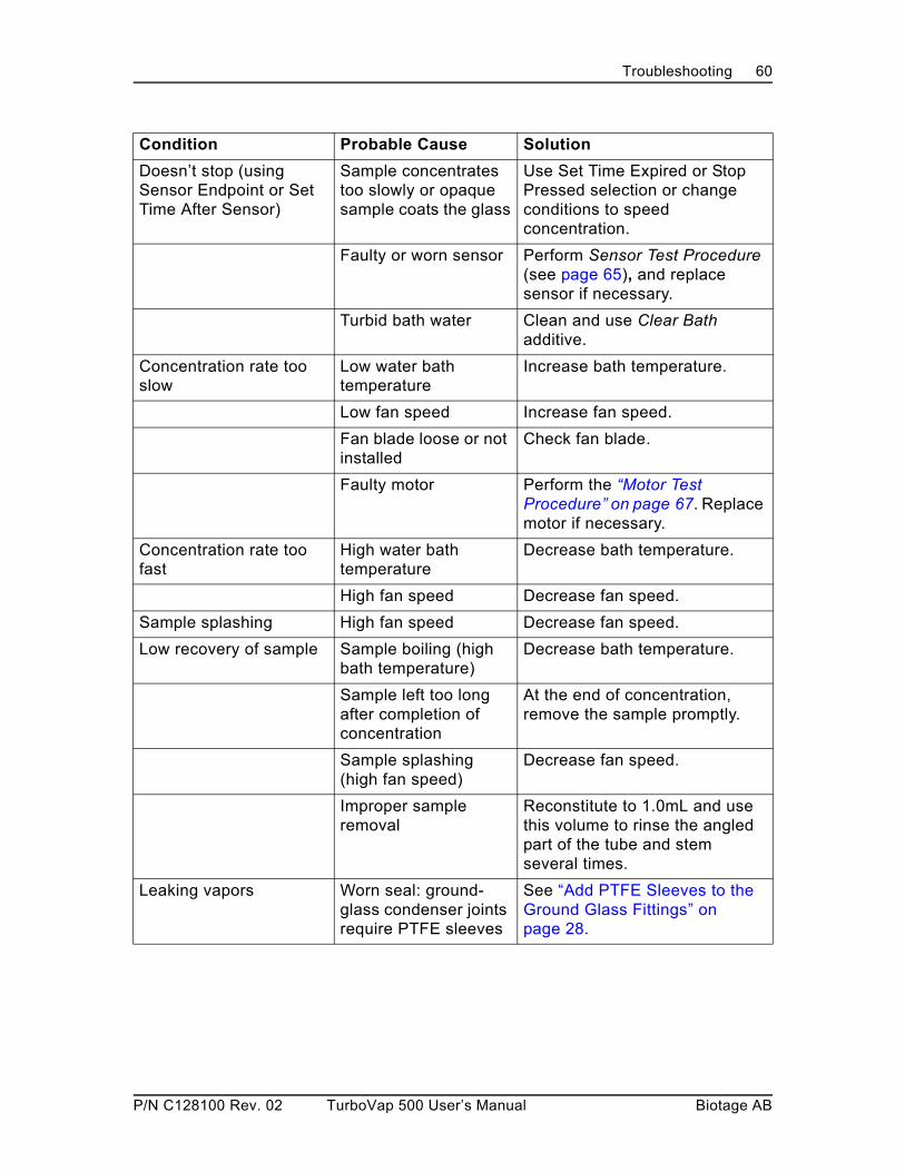
Troubleshooting 60
Doesn’t stop (using Sensor Endpoint or Set Time After Sensor)
Sample concentrates too slowly or opaque sample coats the glass
Use Set Time Expired or Stop Pressed selection or change conditions to speed concentration.
Faulty or worn sensor Perform Sensor Test Procedure (see page 65), and replace sensor if necessary.
Turbid bath water Clean and use Clear Bath additive.
Concentration rate too slow
Low water bath temperature
Increase bath temperature.
Low fan speed Increase fan speed.
Fan blade loose or not installed
Check fan blade.
Faulty motor Perform the “Motor Test Procedure” on page 67. Replace motor if necessary.
Concentration rate too fast
High water bath temperature
Decrease bath temperature.
High fan speed Decrease fan speed.
Sample splashing High fan speed Decrease fan speed.
Low recovery of sample Sample boiling (high bath temperature)
Decrease bath temperature.
Sample left too long after completion of concentration
At the end of concentration, remove the sample promptly.
Sample splashing (high fan speed)
Decrease fan speed.
Improper sample removal
Reconstitute to 1.0mL and use this volume to rinse the angled part of the tube and stem several times.
Leaking vapors Worn seal: ground-glass condenser joints require PTFE sleeves
See “Add PTFE Sleeves to the Ground Glass Fittings” on page 28.
Condition Probable Cause Solution
P/N C128100 Rev. 02 TurboVap 500 User’s Manual Biotage AB

Troubleshooting 61
Troubleshooting the Panel DisplayTo diagnose unexpected behavior of the panel display, locate the description of the condition in the table below.
Condition Probable Cause Solution
Temperature display blinking
Temperature not in range
Allow enough time to come to temperature. Contact Biotage 1-Point Support if continues.
Temperature display shows “St”, unit beeps rapidly, and bath heater turns off
Temperature setting exceeds maximum allowed when the sensors are installed in the unit (60C).
Decrease temperature setting OR remove sensors and use an endpoint selection that doesn’t use the sensors.
Temperature display shows “Lo”
Bath temperature sensor shorted
Contact Biotage 1-Point Support (see page 4).
Temperature display shows “hi”
Bath temperature sensor open or unplugged
Contact Biotage 1-Point Support (see page 4).
Time display shows “” Elapsed time has exceeded 99 minutes - using Stop Pressed selection
Normal behavior.
Time display shows “SE” using Sensor Endpoint or Time After Sensor selection
Normal behavior.
Endpoint selection and fan speed lights blinking and Time=00
Power failure occurred Evaluate the concentration status, reset, and restart.
Light out on panel Faulty LED Replace the electronics cover or contact Biotage 1-Point Support (see page 4).
Temperature or Time display does not work
Faulty display board Replace the electronics cover or contact Biotage 1-Point Support (see page 4).
Temperature or Time pushwheel does not work or shows the wrong value in the display
Faulty pushwheel switch
Perform the “Pushwheel Connection Test” on page 64. If it is not a connection problem, replace the electronics cover.
P/N C128100 Rev. 02 TurboVap 500 User’s Manual Biotage AB

Troubleshooting 62
Troubleshooting the UnitTo diagnose problems with the unit, locate the description of the condition in the table below.
Condition Probable Cause Solution
Unit inoperative Power switch off Check that power switch is turned on.
Loose power cord Check that power cord is fully seated.
Faulty fuse Replace fuse.
Faulty control board Replace control board or contact Biotage 1-Point Support (see page 4).
Turbid bath water Bacterial growth Clean and use Clear Bath additive
Leaking vapors ground-glass condenser joints require PTFE sleeves
See “Add PTFE Sleeves to the Ground Glass Fittings” on page 28.
Difficulty separating glassware
PTFE sleeves on ground glass joints not installed
See “Add PTFE Sleeves to the Ground Glass Fittings” on page 28.
P/N C128100 Rev. 02 TurboVap 500 User’s Manual Biotage AB

Troubleshooting 63
Procedure for Dislodging Bubbles
As the water bath begins to warm up, air comes out of solution and bubbles may form around the sensor’s optics. Also, whenever you have removed the water bath rack for servicing, replacing the rack may trap air bubbles.
In most cases, sample tube insertion frees any bubbles trapped around the sensor’s optics.
In case bubbles trapped in the sensor’s optics affect the concentration process (described in the Diagnostic chart), perform the following steps to dislodge the bubbles:
1 Grasp the sample tube, and using a pumping motion, raise and lower the tube about one inch. Pump the tube up and down several times.
2 Perform step 1 on the other cell position.
3 Test the sensors by performing the “Sensor Test Procedure” on page 65.
Software DiagnosticsThe concentrator software provides diagnostic capabilities to test the function of hardware and check the software version. The following diagnostics are provided:
Power-Up Diagnostics to:
• test the lights on the unit
• check the software version running the unit
• test the Time and Temperature pushwheel connections
Cell Diagnostics to:
• test the sensors
• test the motors
P/N C128100 Rev. 02 TurboVap 500 User’s Manual Biotage AB

Troubleshooting 64
Power Up Diagnostics
The Power Up diagnostics are available each time the power is turned on. Within the first four seconds of turning on the unit, the lights are tested and you can check the software version and the Time and Temperature pushwheel connections.
Display Test
Within the first four seconds of turning power on to the unit, all display lights are lit. If any lights are out, check to make sure all connectors are seated. If condition persists, order the Electronics Cover Replacement Kit. (See “Replacement Parts” on page 70)
Software Version
Press the Fan Speed button within the first four seconds to display the software version in the Temperature display.
Pushwheel Connection Test
The Time and Temperature pushwheel connections should be tested after replacing the control board or electronics cover.
To test the pushwheel connections:
1 While pressing and holding the Fan Speed button, press the top endpoint selection button.
2 Confirm that Temperature and Time display the pushwheel settings.
3 Set each digit to all ten values; the corresponding display should “track” the switch.
If the displays do not reflect the pushwheel settings, the cables may not be connected in the right orientation or at the right receptacle.
IF setting the pushwheel affects the wrong side of the corresponding display, then cables are plugged into the correct connector, but in the wrong orientation.
Figure 31. Wrong Orientation
P/N C128100 Rev. 02 TurboVap 500 User’s Manual Biotage AB

Troubleshooting 65
IF setting the pushwheel affects the display for the other pushwheel, then cables are plugged into the wrong connector.
Figure 32. Wrong Connector
4 Release the fan speed button and the Display Test will resume (for 4 seconds).
Cell Diagnostics
Any time after the Display Test has run, even during operation, cell diagnostics can be performed to test the sensors and the motors.
Enter the Cell diagnostics by pressing either the left cell or the right cell Start/Stop button while holding in the Fan Speed button.
Fan Speed + Cell Start/Stop = Cell diagnostics
Time display = Sensor value
Temperature display = Motor value
The Temperature display reports a value for the brightness of the sensor optics for that cell (left or right). The Time display reports a value for the motor current for that cell (left or right).
Sensor Test Procedure
You should test the sensors:
• when performing routine maintenance
• when suggested by the diagnostic charts.
To test the sensors:
1 Remove any tubes from the unit.
2 While holding the Fan Speed button, press the cell Start/Stop button.
3 Record the value reported in the Temperature display.
no tube:_________
4 Place a clean, empty tube in the position.
P/N C128100 Rev. 02 TurboVap 500 User’s Manual Biotage AB

Troubleshooting 66
5 Record the value reported in the Temperature display.
Empty tube:_________
6 Repeat steps 2-5 for the other cell position.
7 Press the Fan Speed button once to exit the diagnostic mode.
Expected Sensor Values
The table below describes the possible causes for incorrect values.
Perform the “Procedure for Dislodging Bubbles” on page 63 and check the water bath level and sensor connections. After these conditions are ruled out, replace the sensor.
When... Then...
no tube is in place value should be between 10 and 40.
empty tube is in place value should be higher (by about 10) than the “no tube” value.
When... Then...
the value is too high or low
there are bubbles around the sensor opticsorthe water level in the bath is below the level of the sensororthe sensor may be
• improperly connected
• defective
• expired and must be replaced
P/N C128100 Rev. 02 TurboVap 500 User’s Manual Biotage AB

Troubleshooting 67
Motor Test Procedure
You should test the motors:
• when performing routine maintenance
• when suggested by the diagnostic charts.
To test the motors:
1 Select the Stop Pressed endpoint.
2 Press the Fan Speed button until 6000 (C) is selected and KEEP HOLDING THE FAN SPEED BUTTON IN while pressing a cell Start/Stop button.
3 Release the Fan Speed button and press the cell’s Start/Stop button to start the fan.
4 Once the fan reaches a steady speed, record the value reported in the Time display.6000 rpm:_________
5 Press the cell’s Start/Stop button to stop the concentration.
6 Repeat steps 2-5 for the other cell position.
7 Press the Fan Speed button once to exit the diagnostic mode.
Expected Motor Current Values
The table below describes the possible causes for incorrect values.
Check for the conditions described. After these conditions are ruled out, replace the motor.
When... Then...
no concentration is in process value should be 0 or 1.
a steady speed is reached at:4000rpm5000rpm6000rpm7000rpm8000rpm
value should be between 2 and 6.value should be between 3 and 7.value should be between 4 and 8.value should be between 4 and 9.value should be between 5 and 10.
When... Then...
The value is above 15 when the motor is running
Check for a rubbing shaft or other source of friction.
The value continues to climb, or exceeds 30
Check that the fan shaft is free to turn and that the motor is plugged in correctly.
P/N C128100 Rev. 02 TurboVap 500 User’s Manual Biotage AB

Specifications 68
Specifications
Capacity: 2 samples, up to 500mL each
Water Bath Temperature Range:
ambient to 95CCan cool below ambient by using the evaporation as a cooling source. Sensors must be removed to use above 60C.
Condenser Coolant Temperature Range:
4C- 20CUsing low temperatures, without freezing, will increase the concentration rate and improve solvent reclamation and sample recovery.
Dimensions: Height: 24.0" (60.9 cm)Width: 21.2" (53.8 cm)Depth: 11.9" (30.2 cm)Weight: 40.5 lbs (18.47 Kg) - empty water bath
Operating Temperature
59° to 95°F (15° to 35°C)
Operating Humidity
0% to 85% relative humidity, non-condensing
Storage Temperature
50° to 122°F (10° to 50°C)
Storage Humidity
0% to 85% relative humidity, non-condensing
Altitude Up to 2000M
Indoor Use Only
Input Voltage 100/120VAC +/- 10%220/240 VAC +/- 10%
Line Frequency
50 - 60 Hz
Fuses 100/120VAC: (1) 10A, T250V (P/N 39164)220/240 VAC: (2) 5A, T250V (P/N 44412)
P/N C128100 Rev. 02 TurboVap 500 User’s Manual Biotage AB

Specifications 69
Containers: Biotage glass concentration tubes with 0.5mL or 1.0* mL stemPyrex can be baked at up to 450C*When using sensor endpoint detection and tubes with 1.0mL stems, concentrate to a volume of 0.75mL. There is a calibrated mark on the sample tube indicating a volume of 1.0mL if you want to reconstitute the sample to this volume.
Accuracy of 1.0mL stem and graduated glassware:1.0mL graduation: ± 0.02 mL5, 10, and 50mL graduations:± 0.5 mL100 and 200mL graduations:± 2.0 mL
Time Range: 1-99 min.
Fan Speed: 5 settings - 4000, 5000, 6000, 7000 and 8000 rpm
Solvent Reclamation:
95% of solvent vapors under typical conditions
P/N C128100 Rev. 02 TurboVap 500 User’s Manual Biotage AB

Replacement Parts 70
Replacement Parts
TurboVap Units
Accessories
Glassware
UnitsPart Number
TurboVap 500, 110/120V, — includes 1.0mL stem tubes, caps, blades, auxiliary rack and sleeve kit & toolNOTE:1.0mL recommended for best recoveries with semi-volatiles0.5mL stem tubes for non-volatiles are also available
C103202
TurboVap 500, 230V, — includes 1.0mL stem tubes, caps, blades, auxiliary rack and sleeve kit & toolNOTE:1.0mL recommended for best recoveries with semi-volatiles0.5mL stem tubes for non-volatiles are also available
C103203
AccessoriesPart Number
Auxiliary Rack, 2-position, 500mL tubes C45400
Closed Cell Assembly Set 1.0mL stemincludes 1 ea: sample tube, condenser and cell cap
C128142
Closed Cell Assembly Set 0.5mL stemincludes 1 ea: sample tube, condenser and cell cap
C128143
Glass Covers for 500mL sample tubes (2 ea) C45412
GlasswarePart Number
Condenser C128136
Cell Caps (2/set) C45210
Concentration Sample Tube, 1.0mL stem, 500mL (2 ea)recommended for best recoveries with semi-volatiles
C128140
P/N C128100 Rev. 02 TurboVap 500 User’s Manual Biotage AB

Replacement Parts 71
Replacement Kits
Spare Parts
Concentration Sample Tube, 0.5mL stem, 500mL (2 ea)recommended for best recoveries with non-volatiles
C128137
Concentration Sample Tube, flat bottom, 500mL (2 ea)recommended for best recoveries with non-volatiles
C128141
GlasswarePart Number
Replacement KitsPart Number
Electronics Cover Replacement Kit (with keypad) C103211
Control Board Replacement Kit C45711
Drain Tubing Replacement Kit C45709
Sensor Replacement Kit C45713
Motor Replacement Kit C46803
Condenser Tubing Replacement Kit C50197
Bath Replacement Kit C46985
Spare PartsPart Number
Motor Cover C45224
Fitting-coupling, panel-mount, 1/8 — inlet/outlet couplings on unit
C45350
Fitting-coupling insert, right angle, 1/8 barb — connects Condenser tubing to unit
C45351
Fitting-coupling, right angle, 1/4 barb — connects ¼” chiller tubing to unit
C45352
Cap, screw-on — connects drain tubing to Condenser
C45355
Fan Assembly (internal cooling fan) C45362
Interconnect Board C45705
Drain Cap Insert (1 ea) C45771
Gasket — on fitting in screw cap which to Condenser C45776
P/N C128100 Rev. 02 TurboVap 500 User’s Manual Biotage AB

Replacement Parts 72
Miscellaneous Items
PTFE Sleeve Kit (4/pkg) — for ground glass joints: requires 46433
C46431
PTFE Sleeve Installation Tool —required for 46431 C46433
PTFE Washer, 0.45 OD x 0.25 ID x 0.02 THK— in PTFE seal placed in glass Cell Cap
C46686
Fan Blades and Shaft (2/set) C46801
PTFE Seals for Fan Shaft (10 ea/pkg) C46802
Bearing, 0.6 OD x 0.25 ID x 0.2 ED, 0.69 diameter — in motor mount
C47568
Mount for the Motor and Bearing — mount only; no bearings or hardware
C47569
Spare PartsPart Number
Miscellaneous ItemsPart Number
Water Bath Additive, Clear Bath - 8 oz. bottle C44316
Bath Siphon C46381
P/N C128100 Rev. 02 TurboVap 500 User’s Manual Biotage AB

Index 73
IndexNumerics
0.5 mL sample tube . . . . . . . . . . . . . 131.0 mL sample tube . . . . . . . . . . . . . 13
removing sample . . . . . . . . . . . . . 42
A
Accessories . . . . . . . . . . . . . . . . . . . 70Accuracy. . . . . . . . . . . . . . . . . . . . . . 69Adding sample . . . . . . . . . . . . . . . . . 45Alarm behavior . . . . . . . . . . . . . . . . . 46Alarm volume control . . . . . . . . . . . . 16Antifreeze . . . . . . . . . . . . . . . . . . . . . 37Assembling
closed cell . . . . . . . . . . . . . . . . . . 29motor, cell cap, and fan blade . . . 26
Automated concentration features. . . 13
B
Baking the glassware . . . . . . . . . . . . 51Baseline . . . . . . . . . . . . . . . . . . . . . . 40Bath capacity . . . . . . . . . . . . . . . . . . 24Bath cover, removing . . . . . . . . . . . . 55Bearings
ordering. . . . . . . . . . . . . . . . . . . . 72replacing . . . . . . . . . . . . . . . . . . . 49
Bench location . . . . . . . . . . . . . . . . . 25Best recoveries . . . . . . . . . . . . . . . . . 42Bevaline . . . . . . . . . . . . . . . . . . . . . . 22Bubbles
dislodging . . . . . . . . . . . . . . . . . . 63troubleshooting . . . . . . . . . . . . . . 59
Buzzer . . . . . . . . . . . . . . . . . . . . . . . 16
C
Capacity . . . . . . . . . . . . . . . . . . . . . . 68Cell cap
assembling . . . . . . . . . . . . . . . . . 26ordering. . . . . . . . . . . . . . . . . . . . 70parts . . . . . . . . . . . . . . . . . . . . . . 20
Cell diagnostics . . . . . . . . . . . . . . . . 65Cell selections . . . . . . . . . . . . . . . . . 19Changing the fuses . . . . . . . . . . . . . . 52Chiller
choosing temperature . . . . . . . . . 37
connecting . . . . . . . . . . . . . . . . . . 33requirements . . . . . . . . . . . . . . . . 24using . . . . . . . . . . . . . . . . . . . . . . 44
Clarity . . . . . . . . . . . . . . . . . . . . . . . . 40Cleaning
baking glassware . . . . . . . . . . . . . 51exterior . . . . . . . . . . . . . . . . . . . . . 48glassware . . . . . . . . . . . . . . . . . . . 50panel . . . . . . . . . . . . . . . . . . . . . . 48rinsing with solvent . . . . . . . . . . . . 51solvent evaporation . . . . . . . . . . . 51water bath . . . . . . . . . . . . . . . . . . 53
Clear Bathadding . . . . . . . . . . . . . . . . . . . . . 34cleaning the water bath. . . . . . . . . 53included . . . . . . . . . . . . . . . . . . . . 24maintenance. . . . . . . . . . . . . . . . . 50ordering . . . . . . . . . . . . . . . . . . . . 72refilling water bath . . . . . . . . . . . . 54troubleshooting . . . . . . . . . . . . . . . 60
Closed Celladding sample . . . . . . . . . . . . . . . 45assembling . . . . . . . . . . . . . . . . . . 29disassembly . . . . . . . . . . . . . . . . . 46ordering . . . . . . . . . . . . . . . . . . . . 70parts . . . . . . . . . . . . . . . . . . . . . . . 20
Concentrate Until options . . . . . . . . . . 18Concentration
conditions . . . . . . . . . . . . . . . . . . . 36final conditions . . . . . . . . . . . . . . . 43starting . . . . . . . . . . . . . . . . . . . . . 45stopping . . . . . . . . . . . . . . . . . . . . 46
Concentrator tube parts . . . . . . . . . . . 21Condenser
consumables . . . . . . . . . . . . . . . . 49glassware maintenance . . . . . . . . 50holding cups . . . . . . . . . . . . . . . . . 15ordering . . . . . . . . . . . . . . . . . . . . 70parts . . . . . . . . . . . . . . . . . . . . . . . 21
Condenser coolantchoosing temperature . . . . . . . . . . 37specifications . . . . . . . . . . . . . . . . 68
Condenser In, connecting . . . . . . . . . 33Condenser Out, connecting . . . . . . . . 33Container specifications . . . . . . . . . . . 69Coolant
connecting . . . . . . . . . . . . . . . . . . 33
P/N C128100 Rev. 02 TurboVap 500 User’s Manual Biotage AB

Index 74
inlet and outlet. . . . . . . . . . . . . . . 17Coolant supply . . . . . . . . . . . . . . . . . 32
choosing . . . . . . . . . . . . . . . . . . . 37connecting tubing lines . . . . . . . . 32Inlet . . . . . . . . . . . . . . . . . . . . . . . 32Out . . . . . . . . . . . . . . . . . . . . . . . 33required. . . . . . . . . . . . . . . . . . . . 23
D
Daily maintenance . . . . . . . . . . . . . . 48Dark samples
choosing endpoint . . . . . . . . . . . . 39troubleshooting . . . . . . . . . . . . 59, 60
Diagnosticscell . . . . . . . . . . . . . . . . . . . . . . . 65display test . . . . . . . . . . . . . . . . . 64motor test . . . . . . . . . . . . . . . . . . 67pushwheel connection . . . . . . . . . 64sensor test . . . . . . . . . . . . . . . . . 65software version test . . . . . . . . . . 64
Dimensions. . . . . . . . . . . . . . . . . . . . 68Dislodging bubbles . . . . . . . . . . . . . . 63Display
test . . . . . . . . . . . . . . . . . . . . . . . 64test on power-up . . . . . . . . . . . . . 35troubleshooting . . . . . . . . . . . . . . 61
Distilled wateradding . . . . . . . . . . . . . . . . . . . . . 34refilling water bath . . . . . . . . . . . . 54required. . . . . . . . . . . . . . . . . . . . 24
Done light . . . . . . . . . . . . . . . . . . . 19, 46Drain Tubing
connecting. . . . . . . . . . . . . . . . . . 30kit included . . . . . . . . . . . . . . . . . 22required. . . . . . . . . . . . . . . . . . . . 24
E
Endpoint selectionsSensor Endpoint . . . . . . . . . . . . . 18Set Time After Sensor . . . . . . . . . 18Set Time Expired. . . . . . . . . . . . . 18Stop Pressed. . . . . . . . . . . . . . . . 18
Endpoint, selecting . . . . . . . . . . . . . . 39Evaporation rate . . . . . . . . . . . . . . 37, 38Expected motor current values . . . . . 67Expected sensor values . . . . . . . . . . 66Exterior, cleaning . . . . . . . . . . . . . . . 48
F
Fan . . . . . . . . . . . . . . . . . . . . . . . . . . 16behavior . . . . . . . . . . . . . . . . . . . . 46troubleshooting . . . . . . . . . . . . . . . 59
Fan bladeassembling . . . . . . . . . . . . . . . . . . 26cleaning . . . . . . . . . . . . . . . . . . . . 51installing . . . . . . . . . . . . . . . . . . . . 27
Fan speedbutton . . . . . . . . . . . . . . . . . . . . . . 19considerations . . . . . . . . . . . . . . . 38selecting . . . . . . . . . . . . . . . . . . . . 38selections . . . . . . . . . . . . . . . . . . . 19specifications . . . . . . . . . . . . . . . . 69
Filling the water bath . . . . . . . . . . . . . 34Freezing. . . . . . . . . . . . . . . . . . . . . . . 37Front panel
parts . . . . . . . . . . . . . . . . . . . . . . . 17troubleshooting . . . . . . . . . . . . . . . 61
Front view . . . . . . . . . . . . . . . . . . . . . 15Fuse specifications . . . . . . . . . . . . . . 68Fuses
included . . . . . . . . . . . . . . . . . . . . 24replacing. . . . . . . . . . . . . . . . . . . . 52
G
Gas Vortex Shearing action . . . . . . . . 12Glassware
assembling . . . . . . . . . . . . . . . . . . 29baking. . . . . . . . . . . . . . . . . . . . . . 51cleaning . . . . . . . . . . . . . . . . . . . . 50maintenance. . . . . . . . . . . . . . . . . 50ordering . . . . . . . . . . . . . . . . . . . . 70supplied . . . . . . . . . . . . . . . . . . . . 22
Guidelines . . . . . . . . . . . . . . . . . . . . . 42
H
Hardware . . . . . . . . . . . . . . . . . . . . . . 15closed cell . . . . . . . . . . . . . . . . . . 20front panel . . . . . . . . . . . . . . . . . . 17front view . . . . . . . . . . . . . . . . . . . 15rear view. . . . . . . . . . . . . . . . . . . . 16side view . . . . . . . . . . . . . . . . . . . 17
Helical flow. . . . . . . . . . . . . . . . . . . . . 12hi . . . . . . . . . . . . . . . . . . . . . . . . . . . . 61Holding cups . . . . . . . . . . . . . . . . . . . 15Humidity. . . . . . . . . . . . . . . . . . . . . . . 68
P/N C128100 Rev. 02 TurboVap 500 User’s Manual Biotage AB

Index 75
I
In Process light . . . . . . . . . . . . . . . . . 19Inlet connector . . . . . . . . . . . . . . . . . 17
connecting. . . . . . . . . . . . . . . . . . 32Installation . . . . . . . . . . . . . . . . . . . . 22Installing
drain tubing . . . . . . . . . . . . . . . . . 30mounting bracket. . . . . . . . . . . . . 25sensors . . . . . . . . . . . . . . . . . . . . 57TurboVap 500 . . . . . . . . . . . . . . . 25
Introduction. . . . . . . . . . . . . . . . . . . . 12
K
Kits, ordering replacement kits . . . . . 71
L
L= . . . . . . . . . . . . . . . . . . . 18, 40, 41, 45Lights, testing . . . . . . . . . . . . . . . . . . 64Lo . . . . . . . . . . . . . . . . . . . . . . . . . . . 61
M
Maintenance . . . . . . . . . . . . . . . . . . . 48daily . . . . . . . . . . . . . . . . . . . . . . 48glassware . . . . . . . . . . . . . . . . . . 50routine. . . . . . . . . . . . . . . . . . . . . 49water bath . . . . . . . . . . . . . . . . . . 50
Motorassembling . . . . . . . . . . . . . . . 26, 45expected current values . . . . . . . 67installing mounting bracket . . . . . 25mounting bracket. . . . . . . . . . . . . 15parts . . . . . . . . . . . . . . . . . . . . . . 20test . . . . . . . . . . . . . . . . . . . . . . . 67
O
Operating without sensors . . . . . . . . 57Operation . . . . . . . . . . . . . . . . . . . . . 44
preparing. . . . . . . . . . . . . . . . . . . 44Outlet connector . . . . . . . . . . . . . . . . 17
connecting. . . . . . . . . . . . . . . . . . 32
P
Panel, cleaning . . . . . . . . . . . . . . . . . 48Part numbers . . . . . . . . . . . . . . . . . . 70Parts . . . . . . . . . . . . . . . . . . . . . . . . . 15
closed cell . . . . . . . . . . . . . . . . . . 20front panel . . . . . . . . . . . . . . . . . . 17
front view . . . . . . . . . . . . . . . . . . . 15rear view. . . . . . . . . . . . . . . . . . . . 16side view . . . . . . . . . . . . . . . . . . . 17supplied . . . . . . . . . . . . . . . . . . . . 22
Powerrequired . . . . . . . . . . . . . . . . . . . . 24specifications . . . . . . . . . . . . . . . . 68switch . . . . . . . . . . . . . . . . . . . . . . 15troubleshooting . . . . . . . . . . . . . . . 62turning OFF . . . . . . . . . . . . . . . . . 47turning ON . . . . . . . . . . . . . . . . . . 34
Power entry port. . . . . . . . . . . . . . . . . 16changing fuses . . . . . . . . . . . . . . . 52
Power-Up diagnostics . . . . . . . . . . . . 64on start up . . . . . . . . . . . . . . . . . . 35
Preventative maintenance . . . . . . . . . 49PTFE seals
installing . . . . . . . . . . . . . . . . . . . . 27replacement . . . . . . . . . . . . . . . . . 72
PTFE sleeveinstallation tool . . . . . . . . . . . . . . . 72installing . . . . . . . . . . . . . . . . . . . . 28ordering kit . . . . . . . . . . . . . . . . . . 72
PTFE washer, ordering. . . . . . . . . . . . 72Pushwheel . . . . . . . . . . . . . . . . . . . . . 18
testing . . . . . . . . . . . . . . . . . . . . . 64Pyrex container specifications . . . . . . 69
R
r= . . . . . . . . . . . . . . . . . . . . 18, 40, 41, 45Racks
additional . . . . . . . . . . . . . . . . . . . 49replacing. . . . . . . . . . . . . . . . . . . . 56
Recoveryachieving best . . . . . . . . . . . . . . . 42using 1.0 mL sample tubes . . . . . . 42
Removingbath cover . . . . . . . . . . . . . . . . . . 55sample from tube . . . . . . . . . . . . . 47sample tube . . . . . . . . . . . . . . . . . 46sensors. . . . . . . . . . . . . . . . . . . . . 54
Replacement kits . . . . . . . . . . . . . . . . 71Replacement parts . . . . . . . . . . . . . . . 70Replacing
fuses . . . . . . . . . . . . . . . . . . . . . . 52rack . . . . . . . . . . . . . . . . . . . . . . . 56sensors. . . . . . . . . . . . . . . . . . . . . 54
P/N C128100 Rev. 02 TurboVap 500 User’s Manual Biotage AB

Index 76
Routine maintenance . . . . . . . . . . . . 49rpm
considerations . . . . . . . . . . . . . . . 38fan speed selections . . . . . . . . . . 19selecting . . . . . . . . . . . . . . . . . . . 38
S
Sampleadding . . . . . . . . . . . . . . . . . . . . . 45clarity . . . . . . . . . . . . . . . . . . . . . 40recovery temperature . . . . . . . . . 36removing from tube . . . . . . . . . . . 47
Sample tubecleaning . . . . . . . . . . . . . . . . . . . 50consumables . . . . . . . . . . . . . . . . 49maintenance . . . . . . . . . . . . . . . . 50ordering. . . . . . . . . . . . . . . . . . . . 70parts . . . . . . . . . . . . . . . . . . . . . . 21removing . . . . . . . . . . . . . . . . . . . 46removing sample . . . . . . . . . . . . . 47
SE . . . . . . . . . . . . . . . .18, 40, 41, 45, 61Seals
installing . . . . . . . . . . . . . . . . . . . 27ordering. . . . . . . . . . . . . . . . . . . . 72replacing . . . . . . . . . . . . . . . . . . . 49
Selectingconcentration conditions . . . . . . . 36location . . . . . . . . . . . . . . . . . . . . 25
Sensor Endpointconsiderations . . . . . . . . . . . . . . . 40endpoint selection . . . . . . . . . . . . 18using . . . . . . . . . . . . . . . . . . . . . . 40
Sensorsactuate prematurely. . . . . . . . . . . 40consumables . . . . . . . . . . . . . . . . 49disconnecting . . . . . . . . . . . . . . . 56expected values . . . . . . . . . . . . . 66features . . . . . . . . . . . . . . . . . . . . 13installing . . . . . . . . . . . . . . . . . . . 57operating without . . . . . . . . . . . . . 57replacing . . . . . . . . . . . . . . . . . . . 54testing . . . . . . . . . . . . . . . . . . . . . 65unplugging . . . . . . . . . . . . . . . . . 55wear life . . . . . . . . . . . . . . . . . . . 49
Service panel . . . . . . . . . . . . . . . . . . 16removing . . . . . . . . . . . . . . . . . . . 55replacing . . . . . . . . . . . . . . . . . . . 57
Set Time After Sensorconsiderations . . . . . . . . . . . . . . . 41endpoint selection. . . . . . . . . . . . . 18using . . . . . . . . . . . . . . . . . . . . . . 41
Set Time Expiredendpoint selection. . . . . . . . . . . . . 18using . . . . . . . . . . . . . . . . . . . . . . 40
Shearing action . . . . . . . . . . . . . . . . . 12Siphon
changing the water . . . . . . . . . . . . 50cleaning the bath . . . . . . . . . . . . . 53ordering . . . . . . . . . . . . . . . . . . . . 72
Site preparation . . . . . . . . . . . . . . . . . 23Software diagnostics . . . . . . . . . . . . . 63Software version, viewing. . . . . . . . . . 64Solvent
evaporation. . . . . . . . . . . . . . . . . . 51recovering . . . . . . . . . . . . . . . . . . 42rinsing . . . . . . . . . . . . . . . . . . . . . 51
Solvent reclamation . . . . . . . . . . . . . . 30specifications . . . . . . . . . . . . . . . . 69
Solvent vapors . . . . . . . . . . . . . . . 12, 14Spare parts. . . . . . . . . . . . . . . . . . 70, 71Specifications. . . . . . . . . . . . . . . . . . . 68Start/Stop button . . . . . . . . . . . . . . . . 19Starting
concentration . . . . . . . . . . . . . . . . 45new baseline reading . . . . . . . . . . 40TurboVap . . . . . . . . . . . . . . . . . . . 44
Stop Pressedendpoint selection. . . . . . . . . . . . . 18using . . . . . . . . . . . . . . . . . . . . . . 41
Stopped light . . . . . . . . . . . . . . . . 19, 46Stopping
concentration . . . . . . . . . . . . . . . . 46troubleshooting . . . . . . . . . . . . . . . 60
T
Tap water . . . . . . . . . . . . . . . . . . . . . . 17required . . . . . . . . . . . . . . . . . . . . 23using . . . . . . . . . . . . . . . . . . . . . . 37
Temperaturecondenser coolant . . . . . . . . . . . . 37condenser coolant specifications . 68coolant considerations . . . . . . . . . 37display . . . . . . . . . . . . . . . . . . . . . 18high temperatures. . . . . . . . . . . . . 54
P/N C128100 Rev. 02 TurboVap 500 User’s Manual Biotage AB

Index 77
operating . . . . . . . . . . . . . . . . . . . 68pushwheel . . . . . . . . . . . . . . . . . . 18setting water bath . . . . . . . . . . . . 37specifications . . . . . . . . . . . . . . . 68storage . . . . . . . . . . . . . . . . . . . . 68testing pushwheel . . . . . . . . . . . . 64troubleshooting . . . . . . . . . . . . . . 60troubleshooting display . . . . . . . . 61
Testscell diagnostics . . . . . . . . . . . . . . 65display test . . . . . . . . . . . . . . . . . 64motor. . . . . . . . . . . . . . . . . . . . . . 67pushwheel connection . . . . . . . . . 64sensors . . . . . . . . . . . . . . . . . . . . 65software version . . . . . . . . . . . . . 64
Timedisplay. . . . . . . . . . . . . . . . . . . . . 18display during operation . . . . . . . 45exceeds 99 minutes . . . . . . . . . . 45pushwheel . . . . . . . . . . . . . . . . . . 18selecting . . . . . . . . . . . . . . . . . . . 39testing pushwheel . . . . . . . . . . . . 64troubleshooting pushwheel . . . . . 61
Time Range specifications . . . . . . . . 69Tools needed for installation . . . . . . . 23Troubleshooting . . . . . . . . . . . . . . . . 59
concentration . . . . . . . . . . . . . . . 59display. . . . . . . . . . . . . . . . . . . . . 61general . . . . . . . . . . . . . . . . . . . . 62power . . . . . . . . . . . . . . . . . . . . . 62preventive maintenance . . . . . . . 49
Tubing clips, installing. . . . . . . . . . . . 30Turning OFF . . . . . . . . . . . . . . . . . . . 47Turning ON . . . . . . . . . . . . . . . . . . . . 34
U
Unpacking. . . . . . . . . . . . . . . . . . . . . 22
V
Vaporstroubleshooting . . . . . . . . . . . . . . 60
Ventfeatures . . . . . . . . . . . . . . . . . . . . 14
Ventilation source . . . . . . . . . . . . . . . 31Version test. . . . . . . . . . . . . . . . . . . . 64Volatile compounds. . . . . . . . . . . . . . 36Vortex . . . . . . . . . . . . . . . . . . . . . . . . 12
W
Washing sample tubes . . . . . . . . . . . . 50Waste container, selecting . . . . . . . . . 30Water bath . . . . . . . . . . . . . . . . . . . . . 15
cleaning . . . . . . . . . . . . . . . . . . . . 53filling. . . . . . . . . . . . . . . . . . . . . . . 34maintenance. . . . . . . . . . . . . . . . . 50refilling . . . . . . . . . . . . . . . . . . . . . 54selecting temperature . . . . . . . . . . 36setting temperature. . . . . . . . . . . . 37specifications . . . . . . . . . . . . . . . . 68temperature considerations . . . . . 37
Water bath temperature . . . . . . . . . . . 13display . . . . . . . . . . . . . . . . . . . . . 18pushwheel . . . . . . . . . . . . . . . . . . 18troubleshooting . . . . . . . . . . . . . . . 60
P/N C128100 Rev. 02 TurboVap 500 User’s Manual Biotage AB

Biotage, AB10430 Harris Oaks Blvd, Suite CCharlotte, NC 28269TEL +1 704 654 4900Toll Free +1 800 446 4752FAX +1 704 654 4917http://www.biotage.com