TURBOSEIS - An Interactive Program For Constructing … · TURBOSEIS - An Interactive Program For...
83
USGS-OFR-89-567A USGS-OFR-89-567A UNITED STATES DEPARTMENT OF THE INTERIOR GEOLOGICAL SURVEY TURBOSEIS - An Interactive Program For Constructing and Editing Models of Seismic Refraction Traveltime Data Using A Color-Graphics Terminal By B. A. Chuchel 1989 Open-File Report 89-567A Prepared in cooperation with the Nevada Operations Office U.S. Department of Energy (Interagency Agreement DE-AI08-78ET44802) This report is preliminary and has not been reviewed for conformity with U.S. Geological Survey editorial standards (or with the North American Stratigraphic Code). Any use of trade, product or firm names is for descriptive purposes only and does not imply endorsement by the U.S. Government. Although this program has been used by the U.S. Geological Survey, no warranty, expressed or implied, is made by the USGS as to the accuracy and functioning of the program and related program material nor shall the fact of distribution constitute any such warranty, and no responsibility is assumed by the USGS in connection therewith. Menlo Park, California 1989
Transcript of TURBOSEIS - An Interactive Program For Constructing … · TURBOSEIS - An Interactive Program For...

USGS-OFR-89-567A USGS-OFR-89-567A
UNITED STATES DEPARTMENT OF THE INTERIOR
GEOLOGICAL SURVEY
TURBOSEIS - An Interactive Program For Constructingand Editing Models of Seismic Refraction Traveltime
Data Using A Color-Graphics Terminal
By
B. A. Chuchel
1989
Open-File Report 89-567A
Prepared in cooperation with theNevada Operations Office
U.S. Department of Energy(Interagency Agreement DE-AI08-78ET44802)
This report is preliminary and has not been reviewed for conformity with U.S. Geological Survey editorial standards (or with the North American Stratigraphic Code). Any use of trade, product or firm names is for descriptive purposes only and does not imply endorsement by the U.S. Government.
Although this program has been used by the U.S. Geological Survey, no warranty, expressed or implied, is made by the USGS as
to the accuracy and functioning of the program and related program material nor shall the fact of distribution constitute any such
warranty, and no responsibility is assumed by the USGS in connection therewith.
Menlo Park, California 1989

Contents
1 Introduction 4
2 The Modeling Process 6
3 Input and Output Files 8
4 General Instructions 04.1 Notations Used in This Manual ................... 94.2 Default Answers ........................... 94.3 Obtaining Help ............................ 104.4 Quitting a Sublevel (Bailing Out) .................. 104.5 Distance, Time, and Velocity Units Recognized By TURBOSEIS 114.6 Conventions Used in Program .................... 114.7 Cross-Hair Graphics Cursor, Mouse Buttons, and Numeric Keypad 12
4.7.1 Screen Coordinates ...................... 134.7.2 Moving the Graphics Cursor With the Mouse ....... 134.7.3 Moving the Graphics Cursor via Numeric Keypad .... 14
4.8 Message When a Boundary is Required .............. 154.9 Moving and Positioning Objects .................. 164.10 Intercept Times, Reciprocal Points, and Symbols ......... 164.11 Command Line Scripting ...................... 174.12 VAX/VMS Commands & TURBOSEIS .............. 19
5 Running the Program 225.1 Input/Output ............................. 23
5.1.1 Reading in a TURBOSEIS Model ............. 245.1.2 Writing TURBOSEIS Model ................ 275.1.3 Reading in an OTX File ................... 275.1.4 Writing T-layer File ..................... 29
5.2 Editing the Model .......................... 305.2.1 Adding Points to the Model ................. 325.2.2 Deleting Points From the Model .............. 34

5.2.3 Moving Points in the Model ................. 365.2.4 Special Functions ....................... 38
5.2.4.1 Copying a Section of the Model ......... 395.2.4.2 Constructing Intercept Times ........... 405.2.4.3 Mirroring a Section of the Model ......... 425.2.4.4 Constructing Parallel Lines ............ 435.2.4.5 Constructing Reciprocal Times .......... 45
5.2.5 See a Screen Position ..................... 465.2.6 Editing Symbols ....................... 47
5.2.6.1 Copying a Symbol ................. 485.2.6.2 Deleting a Symbol ................. 495.2.6.3 Moving a Symbol ................. 51
5.2.7 Displaying the Velocities Along a Layer of the Model ... 525.2.8 Velocity Layer Construction ................. 54
5.3 Miscellaneous Functions ....................... 555.3.1 Changing the Layer Number For a Section of the Model . 565.3.2 Removing Redundant Model Points ............ 575.3.3 Removing Model Points Having T < 0.0 .......... 58
5.4 Select View .............................. 595.4.1 Set View ........................... 60
5.4.1.1 Setting Visibility of Layers in Model ....... 615.4.1.2 Setting the Visible X-Range ........... 62
5.4.2 Suppressing OTX Data From Display ........... 635.4.3 Viewing a Point in the TURBOSEIS Model ........ 64
5.5 Zoom ................................. 655.5.1 Selecting a Subregion for Zooming ............. 67
5.5.1.1 Entering Subregion Via Cursor Positions .... 675.5.1.2 Keyboard Entered Subregion ........... 68
5.5.2 Recalling a Previous Zoom State .............. 695.6 Quitting the Program ........................ 69
6 NOTES ON IMPLEMENTATION 716.1 Distribution Tape for VAX/VMS Systems and Linking to use DCL 716.2 ANSI Distribution Tape of TURBOSEIS .............. 726.3 Contents of 5 1/4 inch Diskette ................... 726.4 Graphics Routines Called Within Program ............. 746.5 Author Address ............................ 74
7 REFERENCES 75
A Files Used By TURBOSEIS 76A.I TURBOSEIS Model File Format .................. 76A.2 OTX File Format ........................... 79A.3 T-layer File Format ......................... 81

List of Figures
4.1 Sample TURBOSEIS Screen ..................... 13
5.1 TURBOSEIS Command Menu ................... 235.2 Input/Output Menu ......................... 245.3 Screen After TURBOSEIS Model Read. .............. 265.4 Terminal Screen After OTX Read. ................. 285.5 Edit Command Menu ........................ 315.6 Special Functions Options ...................... 395.7 Symbol Editing Options ....................... 485.8 Miscellaneous Features of Program ................. 565.9 Select Menu .............................. 605.10 Zoom Menu .............................. 665.11 Screen after Zooming ......................... 68

Chapter 1
Introduction
TURBOSEIS is a FORTRAN computer program designed to assist the user in interactively developing seismic refraction traveltime curves (models), to evalu ate the number of refracting horizons at depth in a study area. TURBOSEIS allows one to generate a detailed traveltime curve for each of these layers that can then be input into the programs of Ackermann [Ackermann and others 1986] for inversion of the velocity distribution as a function of depth. This re port describes the mechanics of using the program to enter and manipulate the "model".
An outline of the modeling process, and the method embodied in this pro gram, is given in the chapter "The Modeling Process". The chapter "Run ning the Program" describes the commands and actions used to enter and de scribe the model. The "Input and Output Files" chapter describes the files that TURBOSEIS recognizes. "General Instructions" covers background information necessary to use TURBOSEIS.
The TURBOSEIS program is organized in a hierarchical manner; that is, a lower-level can only be reached from a higher-level feature. Figure 5.1 on page 23 shows the organization of the top level of the program. Similar diagrams appear in this manual showing the other features of the program.
TURBOSEIS is written in FORTRAN 77 and is designed to operate on the Envision 200 or Lear Siegler 7100 series of color-graphics terminals. These termi nals feature a Tektronix 4014 compatible instruction set [Envision, 1983b, Lear Siegler, 1986]. Modular construction of the program should facilitate conversion to other graphics terminals, and the section "Notes on Implementation" pro vides some information on this task. The Open-File Report of Chuchel [Chuchel, 1989B] is a 5 1/4 inch, DOS 2.0 formatted diskette, containing the FORTRAN source code of TURBOSEIS. The contents of this diskette are briefly described in Section 6.3.
TURBOSEIS has been developed in support of the U.S. Geological Survey's effort to characterize potential radioactive waste storage sites at the Nevada

Test Site for the Nevada Nuclear Waste Storage Investigations program.TURBOSEIS was developed under the guidance of Hans Ackermann to allow
for the rapid and advanced analysis of traveltime curves; the tools in the program were implemented specifically to emulate the approach laid out in Ackermann [Ackermann and others 1986].

Chapter 2
The Modeling Process
TURBOSEIS allows the user to build traveltime curves for each subsurface of a model using a variety of editing commands, such as add, delete, copy, and move. The TURBOSEIS model is entered by specifiying which commands to use and how they should be applied. The program has additional options which allow the user to check for matching intercept and reciprocal times, and to determine cross-over points.
The program keeps the current model in memory and applies the changes to this internal model. Before the model in memory is updated, the user is given the opportunity to discard the indicated changes. For graphics operations, the new results (before the changes are made) appear in an "enhanced" color (usually white). A question will appear on the screen when keyboard input is required. Periodically writing the current model to a file will help in the event of a computer error (or crash) or if a mistake is made in an earlier operation.
The following is a rough outline of the steps in constructing a TURBOSEIS model; the section "Running the Program" provides details on the individual steps:
1. The TURBOSEIS program is invoked.
2. The shot point data (.OTX file) is read and displayed on the screen with the time-axis along the vertical and distance-axis along the horizontal.
3. A mouse or other graphics cursor control device is used to draw, edit, and manipulate an initial set of velocity traveltime curves for multiple layers of the model.
4. When satisfied with the current model, a file (the "T-layer" file) is out put and used by independent programs for calculating the depths to the various layers of the model. The TURBOSEIS model is also written to a file.

5. The TURBOSEIS program is invoked again.
6. The TURBOSEIS model file is read in and displayed on the screen.
7. The mouse or cursor keys are used again to add and/or modify the TURBO SEIS model as necessary to improve the agreement between the calculated and observed traveltime curves.
Ackermann [Ackermann and others, 1982] describes the use of intercept and reciprocal times in constructing the model. Under the user's guidance, points in the TURBOSEIS model can be entered to represent these times, as well as mark the points with a symbol (see section 4.10, on page 16, for a list of the symbols and what they signify). The intercept times and reciprocal points are entered by the "Special functions" routines (see section 5.2.4.2 on page 40 and section 5.2.4.5 on page 45). The symbol information is used only within the TURBOSEIS program.

Chapter 3
Input and Output Files
TURBOSEIS recognizes three different file types. The files and the limits on their sizes are described below; Appendix A describes the routines used by TURBOSEIS for reading and writing these files.
1. TURBOSEIS model file. An ASCII formatted file which is both read and written by TURBOSEIS. It contains the information about the points which define the different velocity layers of the model and other infor mation about the structure of the model. The model may contain up to 15 layers. Each shot point may have a total of 400 corner points in the forward and 400 in the reversed direction, to define all the layers. See sec tion 4.6 on page 11 for the definition of forward and reversed directions. Information about the symbols (section 4.10, page 16) are written at the end of this file.
2. OTX file (Observed-Time-Distance) An ASCII formatted file read by the TURBOSEIS program. This file contains the digitized first-arrivals from a set of geophones (one or more shot point(s)). TURBOSEIS limits this file to 20 shot points, each shot point can have a maximum of 400 geophone readings in the forward and reversed directions. This file is output from the programs of Ackermann [Ackermann and others, 1982].
3. T-layer file. An ASCII formatted file output from TURBOSEIS. This file is compatible with the programs of Ackermann [Ackermann and others, 1982] which calculate the depth to a given layer of the model. It is identical in format to the OTX file. TURBOSEIS places no limit on the size of this file. However, the programs of Ackermann [Ackermann and others, 1982] may limit its size.

Chapter 4
General Instructions
This chapter contains general information on using TURBOSEIS. The basics for both keyboard and graphics input, the conventions used in the modeling method, and how to control the mouse are described. Also, the method of command line scripting, and using the extended version of TURBOSEIS in VAX/VMS environments are discussed.
4.1 Notations Used in This Manual
In the examples in this manual the symbol <CR> denotes a carriage return at the end of an input string. If there is blank space between it and the "?" at the end of a question, it means the user entered a carriage return. An answer to a question may be entered in either upper case, lower case, or a combination of both. If an answer is invalid, not understood, or is incomplete, you will be reprompted for input.
The examples in this manual were generated on a DEC (Digital Equipment Corporation) VAX 11/750 running VMS version 4.5.
4.2 Default Answers
A question will appear on the user's terminal when TURBOSEIS requires key board input. Most questions allow only a finite number of responses. The possible choices are enclosed in parentheses at the end of the question, sepa rated by slashes (/). In most cases, a default answer is available and appears between brackets [ ] at the end of the question. The default answer will be used if the user presses the return key. For example, the question,
TURBOSEIS command (e/m/o/s/z/h/q) [H]?

indicates that one of the letters V, "m", "o", V, "z", "h", or "q" is expected from the user and that the letter "h" is the default answer.
4.3 Obtaining Help
Help is available at most points in the program by entering "h" for "help". The resulting message briefly describes the possible courses of action or the type of input required. On entry into the program, the user may select either terse or verbose modes. "Verbose" will cause detailed explanations (when available) to be provided; "terse" provides only a short explanation. In most cases, entering "help" will display the verbose message.
Long help messages are broken into sections. Each section provides a brief explanation on the next material available and a list of user actions. The fol lowing is an example of this type of help message:
More help available on..."Mouse buttons" More help (h/y/n/r/s) [Y]? h
More help options:
Y = Yes, display more information.N = No, leave help message.R = Replay this help message from the beginning.S = Skip to the next help section (if it exists).
More help (h/y/n/r/s) [Y]? n
Typing "y" (or entering a carriage return) would display the material on "Mouse buttons". In a few cases the entire message must be examined; the prompt in these cases is:
Press RETURN to continue ...
4.4 Quitting a Sublevel (Bailing Out)
Entering "q" for "quit" or "//"i moves the program from one sublevel to the next higher level. Generally, if you are in the middle of a long series of operations and decide to quit, or there was a mistake in an earlier entry, entering "//" will return you to an earlier step. Entering "//" will eventually return you to the top level of the program; from there you can exit the program or continue with a different option.
10

4.5 Distance, Time, and Velocity Units Recog nized By TURBOSEIS
For input files, and within the program, the following distance units are recog nized.
KM or KILM = Kilometers. M or METR = Meters. KF or KILF = Kilofeet. FT or FEET = Feet. MI or MILE = Miles.
For time units: (
S or SEC = Seconds. MS or MSEC = Milliseconds.
For units other than the above, you will have to convert your input file(s) to these units, or modify TURBOSEIS to recognize yours.
When a velocity is requested, it may be entered in one of several different formats. As an example, suppose the program displays the message "Enter velocity [5.5 KILM/SEC]". This means the default answer is 5.5 kilometers per second. Other answers could be entered such as the following:
7500 m/s (Meters entered for distance, seconds for time) 7500 m/ (default time units are used, meters used for distance) 7.5 /sec (default distance units are used, seconds used for time) 7.5 (default time and distance units are used) <CR> (Return key pressed, default answer was used)
In some cases the "/" may be omitted, some examples of this are:
KPS = Kilometers/Sec MPS = Meters/Sec FPS = Feet/Sec
The units need not be capitalized. Where units are required in the program, typing "help units" will usually display a complete list of the allowed distance, time, and velocity units.
4.6 Conventions Used in Program
Several conventions used in the TURBOSEIS program require explanation. The first is the "forward" or "reversed" direction from a shot point. The "forward"
11

direction is in the positive X-direction (to the right) along the horizontal axis, conversely, the "reversed" direction is towards the negative direction (left).
Figure 4.1 on page 13 is a sample of what the terminal screen might look like during a modeling session. We define the data window to be the region between the distance-time axes. The vertical blue lines in the data window mark the position of a shot point, the light blue numbers directly below the distance axis are the corresponding shot point numbers (from the OTX file). The light blue numbers appearing in the data window are the locations of the digitized first arrivals for each shot point. The numbers are "folded" into single digits. As an example, shot point number "15" appears below the distance axis as "15", but, the first arrivals are drawn as the number "5" within the data window. Two other notations about numbers in the data window are, sevens (7) are printed as a "*", and ones (1) are printed as an "X". The other lines and symbols represent other components of the model.
Section 5.1.3 on page 27 shows the interactive dialogue in setting up Fig ure 4.1. The units to describe the data were entered in "METR" (for meters) and "MSEC" (for milliseconds), the resulting display has units of kilometers and seconds. TURBOSEIS automatically compresses data ranges when pos sible. When TURBOSEIS requires entry of a number, you usually enter the number in the units used when the screen was originally set up.
While the graphics screen is being drawn, the message "Please Wait" (in green text on top of a red box) appears in the lower left corner of the screen. This message disappears when screen drawing has completed.
A color table appears in the lower right corner of the display. The numbers printed on top of this table represent the mapping of a layer in the model to a color. Note that most of the colors are used several times, and the color associated with layer "1" is only used once. Section 5.4.1.1 describes how to enable and disable the drawing of selected layers in the model.
4.7 Cross-Hair Graphics Cursor, Mouse But tons, and Numeric Keypad
The ENVISION and Lear Siegler terminals provide support for a graphics cross hair cursor which may be controlled from the cursor control keys on the numeric keypad or by a mouse. TURBOSEIS supports screen input via either method.
On startup, TURBOSEIS does not know which method of cursor positioning to use. Hence, the user is prompted for the method of input the first time a screen position is required. The method selected is then used throughout the current invocation of the program.
12

e a-
Figure 4.1: Sample of TURBOSEIS scieen during modeling.
4.7.1 Screen Coordinates
When a scieen location is required, the graphics cuisoi will be activated and the following message will appeal on the terminal screen:
*** Enter coordinates ***
This means that TURBOSEIS is waiting for the cursor to be moved, and for a command to be entered, depending on the method of cursor positioning selected.
4.7.2 Moving the Graphics Cursor With the Mouse
When positioning the graphics cursor, the following actions may be performed using the indicated mouse button:
MOUSE BUTTON
ACTION
1 Enters the current cross-hair cursor position; used primarily for multiple point entry.
2 Same as 1 and informs TURBOSEIS that you are done.
13

3 Help message 2ft3 Quit/abort current action.
The mouse buttons are numbered from left to right when holding the mouse in the right hand. Button one is actuated by the index linger and button three is actuated by the ring finger [Envision, 1983a, Lear Siegler, 1986].
4.7.3 Moving the Graphics Cursor via Numeric Keypad
The cursor can also be controlled with the arrow keys on the numeric keypad. Note that rapid cursor movement can be achieved by simultaneously pressing the FUNCT key and one of the arrow keys. The cursor may be moved in a diagonal direction by simultaneously pressing two diagonally-adjacent arrow keys [Envision, 1983b, Lear Siegler, 1986]. The cursor positioning menu is:
KEYBOARD ACTION CHARACTER
"e" Enters the current cross-hair cursor position; usedprimarily for multiple point entry.
"f" Same as "e" and informs TURBOSEIS that you are done, "h" Help message "q" Quit/abort current action.
In general, when positioning the cross-hair cursor using the numeric keypad, the following steps are followed:
1. The user selects some action requiring the position(s) of the cross-hair cursor. The cross-hairs are then enabled by TURBOSEIS and displayed on the screen.
2. The cursor is moved using the keys on the numeric keypad.
3. The user types a character on the keyboard (the ones listed above) to indicate the desired action.
4. (Optional) When entering multiple points, the user is returned to step 2.
5. (Optional) To quit, enter "q"- This indicates to TURBOSEIS that you do not want any cursor input retained.
6. The user indicates completion by typing a character ("f" or "e") on the keyboard. Generally, when entering multiple points the "f" answer is equivalent to entering "e", but, indicates that the user is done entering positions. After this, the cross-hair cursor is disabled and the user contin ues entering commands from the keyboard. In some cases, TURBOSEIS knows how many points are required, when this limit is reached TURBO SEIS will automatically stop cursor input.
14

On the Envision and Lear Siegler terminals, when moving the cursor with the numeric keypad, the position of the graphics cursor is echoed to the screen as a hexadecimal number. Before entering a command from the keyboard, this final number must be removed from the terminal's input buffer. Use the delete key to erase this string from the screen and then type in a command from the keyboard.
4.8 Message When a Boundary is Required
When TURBOSEIS requires a boundary (two screen positions) to be entered, the following message is displayed. This message is only shown once during the program; the first time a boundary is required.
A boundary is entered by positioning the cross-hair cursor, using either the mouse or keypad cursor keys, to include the point(s) desired between two cursor positions.
NOTE: If there is difficulty in locating the points you want, you will be prompted to reenter the boundaries. In some cases, it may be desirable to ZOOM (where available) to a region to simplify cursor positioning.
When using the mouse or keypad cursor keys, position the cross hair cursor to the desired location on the screen, then type:
(KEY) (MOUSE)e 1 = Enter cross-hair cursor screen location,f 2 = Enter screen location and finish,h 3 = Help message,q 2 ft 3 = Quit.
KEY=KEYBOARD, MOUSE=MOUSE BUTTON(S).
NOTE: When holding the ENVISION mouse in the right hand the mouse buttons are numbered from left to right. Button 1 is actuated by the index finger and button 3 is actuated by the ring finger.
Usually, when a boundary is required, TURBOSEIS really needs two dis tance (X) coordinates; the time (Y) coordinate is not used by the program. If TURBOSEIS requires a time (Y) coordinate too, you will be told to select the boundary more carefully.
15

4.9 Moving and Positioning Objects
TURBOSEIS allows the moving and copying of selected model components; the method for determining how much, and in what direction, an object is displaced has two basic paths. In most cases, a point along the selected object is identified (positioning the cross-hair cursor and entering the position). The following briefly summarizes the path then taken:
1. If the selected object is being positioned simultaneously in the X & Y directions, the new position for the point selected along the object will be entered.
2. Or, if an object is being positioned in the X or Y direction only, the amount the object is shifted is determined by the relative displacement from the new point, to where it intersects with a segment of the object.
As an example of the last case above, suppose a collection of points was being shifted in the time (Y) direction, and the distance (X) coordinate for the new position falls between the X coordinates of two points within the selected object (a segment). The displacement is the difference in the time coordinate of the new position, minus the time coordinate of the intersection (in T-direction) of this point with the segment. If the X coordinate of the new point is to the left or right of the endpoints of the object, the displacement is the difference between the point and the intersection (in T-direction) of the closest segment on the same side as the point extended to this x position. For an object being shifted in the X-direction, the displacement is determined in an analogous manner.
In all cases, the user is provided with detailed instructions on how to proceed and the options available.
4.10 Intercept Times, Reciprocal Points, and Symbols
Certain points in the model are identified as intercept times or reciprocal points. These points are entered using the intercept (Section 5.2.4.2, page 40) and reciprocal (Section 5.2.4.5, page 45) commands. They are marked on the screen with a symbol, and stored in the TURBOSEIS model separately from the model points. At the time they are entered, the points can also be added to the model. The symbols are for the user's use only, and are not used by the programs of Ackermann. The symbols used to mark the intercept and reciprocal points are:
Triangle, apex pointed down = Intercept time for forward direction. Triangle, apex pointed up = Intercept time for reversed direction. Box = Reciprocal point.
16

Figure 5.3 on page 26 shows a model which has all of the above symbol types. The symbols will always fall along a shot point axis and will be associated with a shot point, direction, and layer.
4.11 Command Line Scripting
TURBOSEIS can record the responses entered to questions in a file, or take answers to questions from a user specified file. This method is especially useful when starting up the program and reading in either an OTX or TURBOSEIS model file. The answers can be recorded and then later replayed on a subsequent run of the program. When scripting, the cursor positions entered by the mouse or from keypad operations are not recorded. The following lists the commands to enable and disable this feature.
<filename = Takes subsequent answers to questions from file "filename".
>filename = Records answers to subsequent questions in file "filename".
\ > = Stops recording and closes file.
<* = Echoes the questions and answers read from "filename" to the terminal. To see the questions and answers being read, this command should be invoked before the "<filename" command is entered.
\ < * = Stops subsequent echoing of commands and answers.
In an echoed file, text appearing between a pair of exclamation characters ("!") is treated as a comment. Multiple commands may be entered on the same line separated by semicolons (";"), as in, " T ; h ; 1 ; 25. ; no". The following example shows the recording of commands in a file:
$ r turboseis<CR>********************************************************
Welcome to TURBOSEIS - Version 1.200, 1989/APR/12********************************************************Do you want verbose or terse prompts (v/t/q) [T]? >junk.out<CR>
...Recording commands in file: junk.out Do you want verbose or terse prompts (v/t/q) [T]? <CR> TURBOSEIS command (e/ra/o/s/z/h/q) [H]? o<CR>
*** Input/Output file ***
Input/Output (r/w/ro/t/h/q) [H]? <CR>
Input/Output options:
17

r = Read in a TURBOSEIS model file.w = Write out the current TURBOSEIS model to a file.ro= Read in an OTX file.t = Write out a T layer file.q = Quit and return to TURBOSEIS command.
Input/Output (r/w/ro/t/h/q) [Q]? q<CR> TURBOSEIS command (e/m/o/s/z/h/q) [H]? \> <CR>
...Command recording is OFF... TURBOSEIS command (e/m/o/s/z/h/q) [H]? //<CR> End of TURBOSEIS
Here are the contents of the file created.
! Do you want verbose or terse prompts (v/t/q) [T]?!! TURBOSEIS command (e/m/o/s/z/h/q) [H]?!! TURBOSEIS command (e/m/o/s/z/h/q) [H]?! o! Input/Output (r/w/ro/t/h/q) [H]?!! Input/Output (r/w/ro/t/h/q) [Q]?! q
The following example shows using this file to enter commands and the subsequent dialogue.
$ r turboseis<CR>********************************************************
Welcome to TURBOSEIS - Version 1.200, 1989/APR/12********************************************************Do you want verbose or terse prompts (v/t/q) [T]? <* <CR>
...Command echoing is ON... Do you want verbose or terse prompts (v/t/q) [T]? <junk.out <CR>
...Reading commands from file: junk.out Do you want verbose or terse prompts (v/t/q) [T]? TURBOSEIS command (e/m/o/s/z/h/q) [H]?
TURBOSEIS options:
e = Edit TURBOSEIS model.m = Miscellaneous operations on TURBOSEIS model.o = Input/output various model files.s = Set and select parameters for viewing screen.z = Zoom to a region of the screen.q = Quit TURBOSEIS.
TURBOSEIS command (e/m/o/s/z/h/q) [H]? o
18

*** Input/Output file ***
Input/Output (r/w/ro/t/h/q) [H]?
Input/Output options:
r = Read in a TURBOSEIS model file.w = Write out the current TURBOSEIS model to a file.ro= Read in an OTX file.t = Write out a T layer file.q = Quit and return to the TURBOSEIS command.
...End of command file: JUNK.OUT Input/Output (r/w/ro/t/h/q) [Q]?
At this point the usei could enter additional commands or other script files.
4.12 VAX/VMS Commands & TURBOSEIS
The FORTRAN distribution of TURBOSEIS includes an alternate set of sub routines for use on VAX/VMS systems (see "Notes on Implementation" Sec tion 6.1 for more information on these subroutines). The VAX/VMS version of these subroutines permits access to a major portion of the VAX/VMS command set. Commands issued in this environment are "spawned" to DCL.
VAX/VMS commands are accessed by typing either "_$" or "J&$". The first instruction runs a single command and then returns to TURBOSEIS; the second stays in this sub-environment and continues to spawn commands. A command string can also be added after the "J&" or "_$$"; this command will be processed before continuing.
As an example, suppose during a TURBOSEIS session you receive MAIL from another user. By typing "J& MAIL", you can read and reply to your mail messages. You can also run other programs while in this environment, a potential problem though is runnning a program which generates graphics on the screen. If this occurs, on returning to TURBOSEIS, run the "Zoom" command (see Section 5.5 on page 65), and enter "C" (for Clear) to clear and redraw the screen.
In general, all the VMS commands and global symbols defined at the time TURBOSEIS is invoked are available in this environment. The notable excep tions are the "RECALL" and "LOGOUT" commands. The "LOGOUT" com mand gets spawned to a subprocess, and the subprocess is immediately logged out.
If scripting is on, commands entered in this environment are NOT recorded. Entering "vms help" provides a brief help message. The following is an example of using this feature.
19

$ r turboseis********************************************************Welcome to TURBOSEIS - Version 1.200, 1989/APR/12
********************************************************Do you want verbose or terse prompts (v/t/q) [T]? _$$<CR>
...Escaping to DCL, type "vms help" for assistance. _vmsl: vms help<CR>
Commands issued in this environment are spawned to DCL, when a command completes execution the command prompt is redisplayed. The command prompt is "_vms#: ", where # shows the depth of the spawned environment. A command may be spawned to run unattended (see below). The following commands are recognized and processed before handing off to DCL.
"//" or "Resume" = Quit this environment and return to programat point where it was suspended.
"FORK string" = Spawn a process to run "string" unattended (see below for more info on string format).
"vms help" = Displays this message again.
NOTE: If you issue <CTRL>Y or <CTRL>C while spawned or forked processes (or both) are running, all of the ones running at the current level of spawning will be stopped. The command prompt is then redisplayed.
Press RETURN to continue ... <CR>
The FORK command has two optional parameters, an input and output file. The input file is used if the command being spawned requires input which would normally be obtained from SYS$INPUT, the output file specifies where SYS$OUTPUT should go. The para meters are entered something like the following:
FORK command /SYSIN=JUNK.IN /SYSOUT=JUNK.OUT FORK command /SYSOUTPUT=JUNK.OUT/SYSINPUT=JUNK.IN fork/sysout=junk.out command FORK command
The default input file is NULL.IN (contains a single blank line) located in SYS$MANAGER:, the default output file is SYSOUT.OUT which is written into the current directory.
20
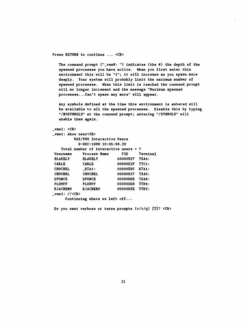
Press RETURN to continue ... <CR>
The command prompt ("_vms#: ") indicates (the #) the depth of the spawned processes you have active. When you first enter this environment this will be "1"; it will increase as you spawn more deeply. Tour system will probably limit the maximum number of spawned processes. When this limit is reached the command prompt will no longer increment and the message "Maximum spawned processes...Can't spawn any more" will appear.
Any symbols defined at the time this environment is entered will be available to all the spawned processes. Disable this by typing "/NOSYMBOLS" at the command prompt; entering "/SYMBOLS" will enable them again.
_vrasl: <CR>_vrasl: show user<CR>
VAX/VMS Interactive Users 9-DEC-1988 10:05:06.20
Total number of interactive users = 7 Username Process Name PID Terminal BLAKELY BLAKELY OOOOOE27 TXA4: CARLE CARLE OOOOOE2F TTC1: CHUCHEL _RTA1: OOOOOE8C RTA1: CHUCHEL CHUCHEL OOOOOE37 TXA5: DPONCE DPONCE OOOOODDE TXA6: PLOUFF PLOUFF OOOOOE5B TTB4: RJACHENS RJACHENS OOOOODEE TTB3:
_vrasl: //<CR>Continuing where we left off...
Do you want verbose or terse prompts (v/t/q) [T]? <CR>
21

Chapter 5
Running the Program
The following sections describe how to run the program. In the examples, messages appearing in a box | *** Like this *** j would appear "enhanced" on your terminal; usually green text on top of a bright white box. Typing "h", at any point in the program, will display a brief help message, entering "help" will usually provide a more detailed explanation.
To begin, enter the command string used to "run" the program. The exam ples given in this manual are for a VAX/VMS operating system.
$ run turboseis********************************************************
Welcome to TURBOSEIS - Version 1.200, 1989/APR/12********************************************************Do you want verbose or terse prompts (v/t/q) [T]? <CR> TURBOSEIS command (e/m/o/s/z/h/q) [H]? <CR>
TURBOSEIS options:
e = Edit TURBOSEIS model.m = Miscellaneous operations on TURBOSEIS model.o = Input/output various model files.s = Set and select parameters for viewing screen.z = Zoom to a region of the screen.q = Quit TURBOSEIS.
TURBOSEIS command (e/m/o/s/z/h/q) [H]? <CR>
We begin by describing how to read and write the various files recognized by the program. We then discuss the other features in the order shown in the TURBOSEIS command prompt above. Figure 5.1 on page 23 shows the options available from the top level of the program.
22

Edit
TURBOSEIS Command
Input/ Output Select
Figure 6.1: TURBOSEIS command menu.
5.1 Input/Output
Here we demonstrate how to read and write the various files recognized by the program. The "Input/Output" prompt is:
TURBOSEIS command (e/m/o/B/z/h/q) [H]? o<CR>
*** Input/Output file ***
Input/Output (r/w/ro/t/h/q) [H]? <CR>
Input/Output options:
r = Read in a TURBOSEIS model file.v = Write out the current TURBOSEIS model to a file.ro= Read in an OTX file.t = Write out a T layer file.q = Quit and return to TURBOSEIS command.
Input/Output (r/w/ro/t/h/q) [Q]?
When the program is started, parameters for drawing objects on the screen must be set. To do this an OTX or TURBOSEIS model must be read in. The
23

Read TURBO
Figure 5.2: Features available from Input/Output menu.
first time either of these files is read, a series of questions is asked about the units used in the file, and for scaling the file to screen. In Section 5.1.3 on page 27 we show reading in an OTX file to set these parameters, and, in Section 5.1.1 on page 24 a TURBOSEIS model is read in. Figure 5.2 on page 24 shows the options available at this point in the program.
5.1.1 Reading in a TURBOSEIS Model
Here we show the two methods for reading in a TURBOSEIS model file. The first case corresponds to when neither an OTX nor TUROBSEIS model file have been read in by the program. The second case corresponds to when an OTX file has already been entered.
Input/Output (r/w/ro/t/h/q) [H]? r<CR>
I *** Read TURBOSEIS model *** |
TURBOSEIS model file name? test.xraa<CR>Units in X direction (FEET/KILF/MILE/METR/KILM/H/Q) [METR]? <CR>Units in T direction (SEC/MSEC/H/Q) [MSEC]? <CR>
The user has entered the name of the TURBOSEIS model file, and the units used in the file.
Tour data ranges are:
Minimum X = -15649.36 Maximum X = 13391.04 (METR)
24

Minimum T = O.OOOOOOOE+00 Maximum T = 4838.SOB (MSEC)
Enter the distance interval to use between the larger tick marksin the X direction.Distance (METR)? 10000<CR>Ticks per division in X direction (0-10, h=help, q=quit) [10]? 5<CR>
Enter the time interval to use between the larger tick marks inthe T direction.Time interval (MSEC)? 2000.<CR>Ticks per division in T direction (0-10, h=help, q=quit) [10]? <CR>
Here the user has described the separation to use between major tick marks and the number of ticks to use in plotting the file on the screen.
By default the display area is initialized to approximately twice the vertical and horizontal ranges of your input data. You can change this now.
Change the display size (y/n) [N]? <CR>
At this point the TURBOSEIS model will be drawn on the screen as in Fig ure 5.3 on page 26. After which, the "Input/Output ..." prompt is redisplayed. In Section 5.1.3 (page 27) we demonstrate the case where the user opted to change the display area.
Remember you haven't read in an OTX file...maybe do it now?
Input/Output (r/w/ro/t/h/q) [Q]?
Now we illustrate reading in a TURBOSEIS model file when an OTX file has already been entered.
Input/Output (r/w/ro/t/h/q) [Q]? r<CR>
| *** Read TURBDSEIS model *** |
TURBOSEIS model file name? test.xma<CR>
At this point the TURBOSEIS model is drawn on the screen, using the scaling parameters given when the OTX file was entered. Figure 4.1 on page 13 shows how the screen would look after reading in this file and drawing on top of an OTX file. After which, the "Input/Output ..." prompt is redisplayed.
25

-3 e17 16 13
Distance ixie KILM>
Figure 5.3: Example of terminal screen after reading in a TURBOSEIS model file.
26
5.1.2 Writing TURBOSEIS Model
Here are the steps in writing the TURBOSEIS model to a file.
Input/Output (r/w/ro/t/h/q) [q]? w<CR>
Output model name [TEST.XMA]? test.xmb<CR>Are you sure (y/n/q) [Y]? y<CR>Tour name (// to quit) [Tour name here]? Joe Sixpack<CR>
Input/Output (r/w/ro/t/h/q) [q]? <CR>
In this example the user is prompted for a name to write in the header of the TURBOSEIS model file. Any string of up to 80 characters may be entered. Also in this example, the user was prompted to confirm if they really wanted a file name different from the default answer.
5.1.3 Reading in an OTX File
Here we demonstrate the two cases when reading in an OTX file. The first case, when TURBOSEIS requests parameters for setting up the screen. The second case, when a TURBOSEIS model file was previously entered.
Input/Output (r/w/ro/t/h/q) [H]? ro<CR>
[ *** Read OTX ** *-|
Name of OTX file? test.otx<CR>Units in X direction (FEET/KILF/MILE/METR/KILM/H/q) [METR]? <CR>Units in T direction (SEC/MSEC/H/q) [MSEC]? <CR>
Tour data ranges are:
Minimum X = -24698.60 Maximum X = 14760.70 (METR) Minimum T = 63.64000 Maximum T = 7618.330 (MSEC)
Enter the distance interval to use between the larger tick marksin the X direction.Distance (METR)? 10000.<CR>Ticks per division in X direction (0-10, h=help, q=quit) [10]? 5<CR>
Enter the time interval to use between the larger tick marks inthe T direction.Time interval (MSEC)? 2000.<CR>Ticks per division in T direction (0-10, h=help, q=quit) [10]? <CR>ft**************************************************************
27

Figure 5.4: Example of terminal screen after reading in OTX file.
By default the display area is initialized to approximately twice the vertical and horizontal ranges of your input data. You can change this now.
Change the display size (y/n) [N]? y<CR>Default = -0.24698500E+05 0.22143000E+05Min and max X range (h=help,//=quit) [DEFAULT]? -30000.0 25000.0<CR>Default = O.OOOOOOOOE+00 0.75183301E+04Min and max T range (h=help,//=quit) [DEFAULT]? 0.0 8000.0<CR>
At this point the OTX file would be drawn on the screen, Figure 5.4 on page 28 shows what this would look like. After the drawing has completed, the user again sees the "Input/Output ..." prompt.
Now we read in an OTX file when a TURBOSEIS model file was previously entered.
Input/Output (r/w/ro/t/h/q) [Q]? ro<CR>
28

I *** Read OTX *** |
Name of OTX file [TEST.OTX]? test.otx<CR>
Tour data ranges are:
Minimum X = -24698.50 Maximum X = 14760.70 (METR) Minimum T = 53.64000 Maximum T = 7518.330 (MSEC)
At this point the OTX file would be drawn on the screen as in Figure 4.1 (page 13) using the scaling parameters given when the TURBOSEIS model was entered. After the drawing is completed, the user again sees the "Input/Output ..." prompt.
5.1.4 Writing T-layer File
Here we demonstrate writing out the T-layer files. This operation requires that a TUROBSEIS model has already been entered. In the example given below, the model had only layer numbers 2, 3, and 4 (a separate output T-layer file is generated for each layer). Error messages are generated for layers not defined in the model, and for layer numbers outside the allowed range. Note the incrementing in layer names for the default answer.
Input/Output (r/w/ro/t/h/q) [Q]? t<CR> Layer number (1-15, h=help, q=quit)? h<CR>
Enter the layer number to output. If your model does NOT contain this layer you will be reprompted for input.
Layer number (1-15, h=help, q=quit)? 3<CR> Name of T-layer file [TEST.T3A]? <CR>
Layer number (1-15, h=help, q=quit)? 3<CR> Name of T-layer file [TEST.T3B]? <CR>
Layer number (1-15, h=help, q=quit)? 4<CR> Name of T-layer file [TEST.T4A]? <CR>
Layer number (1-15, h=help, q=quit)? 12<CR>
No segments found for layer* 12 ...try again.
Layer number (1-15, h=help, q=quit)? 20<CR>
Layer number out of range...try again.
29

Layer number (1-15, h=help, q=quit)? 0<CR>
Layer number out of range...try again.
Layer number (1-15, h=help, q=quit)? -1<CR>
Layer number out of range...try again.
Layer number (1-15, h=help, q=quit)? //<CR>
Input/Output (r/w/ro/t/h/q) [Q]? <CR>
5.2 Editing the Model
Editing the model (usually) consists of identifying and positioning objects on the terminal screen with the graphics cursor. Before the TURBOSEIS model in memory is updated, the user has the option of accepting or rejecting the results. The "Editing" command prompt and menu is:
TURBOSEIS command (e/m/o/s/z/h/q) [H]? e<CR>
*«* Edit *** I
Edit (a/d/m/s/see/sym/v/vl/h/q) [H]? <CR>
Edit options:
a = Add points/line segments to the TURBOSEIS model.d = Delete points/line segments from the TURBOSEIS model.m = Move points/line segments in the TURBOSEIS model.s = Special functions.
see = See the time/space coordinate of a screen position, sym = Symbol editing.v = Draws the velocities on a shot point and layer.vl = Construct a layer with a user entered velocity.q = Quit and return to TURBOSEIS command.
Edit (a/d/m/s/see/sym/v/vl/h/q) [Q]?
Each of these options is described in the following sections. Figure 5.5 shows the options available from this point in the program.
30

uit to Turbo Cmd
Construct Velocity
Special Functions
See
Symbol Editing
Figure 5.5: Edit menu options.
31

5.2.1 Adding Points to the Model
Adding points to the model consists of positioning the graphics cursor and entering a position. The "add" feature has two different methods for entering the points. The "Add" prompt is:
Edit (a/d/m/s/see/sym/v/vl/h/q) [H]? a<CR>
I *** Add seis *** |
Add seis (b/p/h/q) [H]? <CR>
Add seis options:
b = Bound a region of OTX points and least-squares best-fita line through the points between the bounds,
p = Point entry, q = Quit.
Add seis (b/p/h/q) [H]?
We first illustrate the method of "bounding" points in the OTX file. The user enters a shot point number and direction, and then enters two screen positions to mark their boundary. If there are any points (there must be at least two) between the bounding points, TURBOSEIS least-squares best-fits a line through them. The line is drawn on the screen (in white) using the X-coordinates of the two bounding points to mark the ends of the line. When entering the bounding points, only the X-coordinates are important, the T-coordinates are ignored.
Add seis (b/p/h/q) [H]? b<CR>
*** Add bound *** ]
Mouse or cursor keys (m/c/q) [H]? <CR>
*** Add bound loop ***
Enter K (shot) number (1-20, // to quit)? 15<CR>Forwards or reversed from this shot point (f/r/h/q) [R]? <CR>Layer/horizon number (1-15, // to quit)? 4<CR>
At this point the graphics cursor would be activated and the user would position the cursor and enter two screen positions.
*** Enter coordinates ***
*** Enter coordinates ***
32

If there are two or more points in the OTX file falling between the entered boundary points, a least-squares best-fit line is constructed through them. The line is drawn on the screen and the user has the option of adding the two end points of the line to the model.
If there are no points between the user's boundaries, they are reprompted for another pair of screen positions. The following question is asked if points were located within the user's boundary.
Insert point(s) in the TURBOSEIS model (y/n) [Y]? <CR>
If the user answers "y", the points are added to the model and the screen is updated to reflect the addition. If "n" is entered, the line is erased. The add loop of TURBOSEIS allows the user to continue entering points to user specified layers and shot directions. The following example shows how to exit this section.
Layer/horizon number (1-15, // to quit) [5]? //<CR>
I *** Add bound loop *** I
Enter K (shot) number (1-20, // to quit) [15]? //<CR> Add seis (b/p/h/q) [Q]? //<CR>
Edit (a/d/m/s/see/sym/v/vl/h/q) [Q]? //<CR>
Now we demonstrate point entry.
Edit (a/d/m/s/see/sym/v/vl/h/q) [H]? a<CR>
*** Add seis ***
Add seis (b/p/h/q) [H]? p<CR>
*** Add point ***
House or cursor keys (m/c/q) [M]? <CR>
*** Add point loop *** |
Enter K (shot) number (1-20, // to quit)? 15<CR>Forwards or reversed from this shot point (f/r/h/q) [R]? <CR>Layer/horizon number (1-15, // to quit)? 5<CR>
*** Enter coordinates ***
*** Enter coordinates ***
33
*** Enter coordinates ***
*** Enter coordinates ***
*** Enter coordinates ***
*** Enter coordinates ***
Layer/horizon number (1-15, // to quit) [5]? //<CR>
*** Add point loop ***
Enter K (shot) number (1-20, // to quit) [15]? //<CR> Add seis (b/p/h/q) [Q]?
In the above example, the user was in a loop where they entered six points along the layer of interest. The first point along a shot point, direction, and layer is always drawn with a diamond shaped symbol around it. When a second point is added, the diamond symbol is erased and the two points are connected with a straight line. If a point is added between two points in the model, the line connecting them is undrawn and lines are drawn connecting the old points to the new one.
5.2.2 Deleting Points From the Model
Points in the model can be deleted, the "Delete" menu and prompt is:
Edit (a/d/m/s/see/sym/v/vl/h/q) [H]? d<CR>
*** Delete segment ***
Mouse or cursor keys (m/c/q) CM]? <CR> Delete (b/p/h/q) [H]? <CR>
Delete options:
b = Bound the point(s) between two cursor positions.p = Pick a single model point nearest a cursor position.q = Quit and return to Edit.
Delete (b/p/h/q) [H]? b<CR>
The "bound" method lets the user bound the points to delete between two screen positions. The "point" method lets the user delete a model point nearest a screen position. The "bound" method of point removal is first demonstrated.
34

*** Delete segment loop ***
Enter K (shot) number (1-20, // to quit)? 15<CR>Forwards or reversed from this shot point (f/r/h/q) [R]? f<CR>Layer/horizon number (1-15, // to quit)? 4<CR>
Move the cursor and enter two boundary points along the layer of interest.
*** Enter coordinates ***
*** Enter coordinates ***
Are the points or line segments drawn in white the correct ones. Correct (y/n/q) [Y]? <CR>
If there are any points within the user's boundary, the points are drawn in white on the screen. If "y" is answered to the above question, the points are erased from the screen and deleted from the model. If "n" is entered, the points are redrawn in their original color and the user is reprompted to enter another pair of screen positions. If "q" is entered, the user returns to the "Layer/horizon ..." question.
Next we demonstrate removing a single point from the model.
Delete (b/p/h/q) [B]? p<CR>
*** Delete segment loop ***
Enter K (shot) number (1-20, // to quit) [15]? <CR> Forwards or reversed from this shot point (f/r/h/q) [F]? <CR> Layer/horizon number (1-15, // to quit) [4]? 3<CR> Now, select the point of interest along this section.
*** Enter coordinates ***
Are the points or line segments drawn in white the correct ones. Correct (y/n/q) [Y]? <CR> Delete (b/p/h/q) [P]?
In the above example, the user positions the cursor and selects a point in the model along the shot point, direction, and layer they entered. The nearest point in the model to this position (in both X and T directions) is found and is drawn on the screen in white. If "y" is entered, the point is deleted from the model, and the screen is updated to reflect the change. Entering "n", would redraw the point in its original color, enable the graphics cursor, and let the user enter another screen position. If "q" is entered, the user will be returned to the "Layer/horizon ..." prompt.
35

5.2.3 Moving Points in the Model
To move points in the model, the "move" option is invoked:
Edit (a/d/m/s/see/sym/v/vl/h/q) [H]? m<CR>
I *** Move *** I
Mouse or cursor keys (m/c/q) [M]? <CR> Which method to use (b/p/h/q) [H]? <CR>
Move options:
b = Bounding the point(s) between two screen cursor points, p = Pick a single point nearest a cursor position, q = Quit and return to Edit.
Which method to use (b/p/h/q) [H]?
The "bound" method lets the user select a portion of a shot point, direction, and layer of the model to move. The "point" method lets the user move a single point in the model found near a screen position. The bounding method is illustrated first.
Which method to use (b/p/h/q) [H]? b<CR>
*** Move segment loop ***
Enter K (shot) number (1-20, // to quit)? 15<CR>Forwards or reversed from this shot point (f/r/h/q) [R]? f<CR>Layer/horizon number (1-15, // to quit)? 3<CR>
Move the cursor and enter two boundary points along the layer of interest.
*** Enter coordinates ***
*** Enter coordinates ***Are the points or line segments drawn in white the correct ones. Correct (y/n/q) [Y]? <CR> Which direction: X, T, or both XftY (b/x/y/h/q) [H]? h<CR>
Specify the direction(s) to use for this operation. The options are:
8 = Both X and Y directions.
36

X = X direction only. Y = Y direction only. Q = Quit.
Which direction: X, Y, or both XftY (b/x/y/h/q) [Q]? b<CR>
Sorry, this option not supported...try again.
Which direction: X, Y, or both X&Y (b/x/y/h/q) [H]? y<CR>Now move the cursor to the new position for this string of points
*** Enter coordinates *** Insert point(s) in the TURBOSEIS model (y/n) [Y]? <CR>
In the above example, the usei indicated the shot point, diiection, and layei where the section being moved resides. A portion along this section was then indicated. The diiection of motion was selected (only one allowed); the amount of movement is determined by the new cursor position relative to the selected section; see Section 4.9 on page 16 for a more detailed explanation of how this is determined. TURBOSEIS then draws the section in white at the new position and prompts the user if they wish to make the indicated change. If "y" is entered, the old points are erased from the screen, and the new points are drawn in the color appropriate for this layer. If "n" is entered, the new points are undrawn, and the user is reprompted to enter another screen position. If "q" is entered, the new points are undrawn, the old points are redrawn, and the user is returned to the "Layer/horizon ..." prompt.
Next we illustrate moving a model point.
Which method to use (b/p/h/q) [Q]? p<CR>
*** Move single point ***
Enter K (shot) number (1-20, // to quit) [15]? <CR>Forwards or reversed from this shot point (f/r/h/q) [F]? <CR>Layer/horizon number (1-15, // to quit) [3]? <CR>
*** Move single point loop ***
Now, select a point along this layer to move.
*** Enter coordinates ***Are the points or line segments drawn in white the correct ones. Correct (y/n/q) [Y]? <CR>
37

Now, move the cursor to new location for this point.
*** Enter coordinates *** Insert the point(s) (y/n) [T]? <CR>
In the above example, the user indicated the shot point, direction, and layer where the point to move resides. The user then positions the cursor and selects a point, the nearest point in the model along the selected shot point, direction, and layer is located. The point is drawn in white and the user confirms if this is the point they wanted. If it is not their point, the point is redrawn, and the user is reprompted for another screen position. If it is, the user is asked to position the cursor to the new position for this point. The new position is drawn in, and the user elects to make the change or not. If "y" is entered, the old point is undrawn, and the new point is drawn in the color appropriate for this layer. If "n" was entered, the new point would be undrawn, the graphics cursors redisplayed, and the user prompted for another cursor position. If "q" were entered, the new point is erased, the graphics cursor disabled, and the user is returned to the "Layer/horizon ..." prompt.
5.2.4 Special Functions
The "Special functions" perform operations on a collection of points in the model; they also generate the "symbols". The "special functions" prompt is:
Edit (a/d/m/s/see/sym/v/vl/h/q) [Q]? s<CR>
*** Special functions ***
Special functions (c/i/m/p/r/h/q) [H]? <CR>
Special functions options:
c = Copy a section of the TURBOSEIS model to another layer.i = Construct intercept times.m = Mirror a string of points about a shot point.p = Construct parallel lines.r = Construct reciprocal times.q = Quit and return to EDIT.
Special functions (c/i/m/p/r/h/q) [Q]?
Figure 5.6 on page 39 shows the features available from this menu. The "copy" and "parallel" functions are very similar. The copy operation uses a selected corner point along the section being copied, and requests the user enter the new position for this point. The parallel operation lets the user bound a section of the model, and uses properties of the slopes in the indicated section to determine where the section is to be placed; more on this in parallel section.
38

Special Functions
Copy Lines
Intercept Symbols
Mirror Lines
Parallel Lines
Figure 5.6: Special functions options.
5.2.4.1 Copying a Section of the Model
The "copy" prompt is:
Special functions (c/i/m/p/r/h/q) [H]? c<CR>
*** Copy segment ***
House or cursor keys (m/c/q) [M]? <CR>
*** Copy segment loop ***
Reciprocal Symbols
Enter the shot point, direction, and layer to use when extracting points from the model.
Enter K (shot) number (1-20, // to quit)? 17<CR>Forwards or reversed from this shot point (f/r/h/q) [R]? f<CR>Layer/horizon number (1-15, // to quit)? 3<CR>
Move the cursor and enter two boundary points along the layer of interest.
*** Enter coordinates ***
*** Enter coordinates ***
39
The user enters the source where the points will be extracted. The graphics cursor is then displayed and the user bounds the model points of interest. Next, the shot point and layer are entered to indicate where this section will be copied to. The direction becomes the same as the extracted points.
Enter the shot point and layer number where this strip of points will be copied to.Enter K (shot) number (1-20, // to quit)? 15<CR> Layer/horizon number (1-15, // to quit)? 3<CR>
Now, select a point along the segment being copied and enter this position.
*** Enter coordinates ***
Now, move the cursor to the new position for the selected point and enter the position.
*** Enter coordinates ***
The user identifies a model point along the section they are copying, and the location for this same point after copying. The points are drawn in white and the user is prompted if they wish to insert the points in the TURBOSEIS model.
Insert point(s) in the TURBOSEIS model (y/n) [Y]? <CR> Use the same set of points (y/n) [Y]? <CR>
If the user chooses to insert the points, they are redrawn in the color appro priate for this layer. If not, they are erased from the screen. In either case, the same collection of points may be copied to another shot point and layer. The user is in a loop, the following shows how to exit.
Enter the shot point and layer number where this strip of pointswill be copied to.Enter K (shot) number (1-20, // to quit) [17]? //<CR>
Special functions (c/i/m/p/r/h/q) [Q]?
5.2.4.2 Constructing Intercept Times
The method of Ackermann [Ackermann and others, 1982] defines an intercept point as "the intersection of the curve for (a shot point's) ith horizon with the time axis". TURBOSEIS can automatically construct this point and other intersections of a layer with any other "allowed" shot point. An "allowed" shot
40

point, is a shot point which a layet would encounter given its originating shot point and direction. For example, for the forward direction of shot point # 15 in Figure 4.1 (page 13) the allowed shot points are 11, 12, 13, 14, and 15.
When constructing an intercept point, the slope of the nearest segment of the selected layer to the shot point is used. If the shot point happens to cross the layer, then the point of intersection of the model with the shot point is used as the intercept point. If the shot point is to the left or right of the layer, then the slope of the line segment nearest to the shot point is used. The intercept point will be the point of intersection of this line segment extended to the shot point.
The intercept points may be retained as "symbol(s)" separate from the "model" points, although they are written to the TURBOSEIS model file when it is written, they may also be added as points to the model.
Section 4.10 on page 16, describes the two symbols used for the intercept points in the forward or reversed directions. The symbols are drawn in the color of the layer they were constructed from, and can only reside on a shot point axis. The user may edit the symbols, see section 5.2.6 (page 47). The "intercept mode" prompt is:
Special functions (c/i/m/p/r/h/q) [H]? i<CR>
I *** Intercept time ***
Mouse or cursor keys (m/c/q) [M]? <CR>
*** Intercept time loop ***
Enter K (shot) number (1-20, // to quit)? 15<CR>Forwards or reversed from this shot point (f/r/h/q) [R]? f<CR>Layer/horizon number (1-15, // to quit)? 3<CR>
Move the cursor and enter two boundary points along the layer of interest.
*** Enter coordinates ***
*** Enter coordinates ***
The user enters a boundary, and then indicates the shot point intercept to be constructed.
Enter (K) shot point number (0 for originating shot point)Shot number (K) (// to quit) [0]? <CR>Least-squares best-fit a line, or use the entered cursor positionsSelection option (e/l/h/q)? h<CR>
41

When fitting a straight line you have two options:
e = Use the two entered cursor positions to define the slopeof the line.
1 = Least-squares best-fit a line using the points whichfall between the two entered positions,
q = Quit.
Least-squares best-fit a line, or use the entered cursor positionsSelection option (e/l/h/q)? 1<CR>Use OTX data (d) or TURBOSEIS model (m) (d/m/h/q) [M]? <CR>Save point(s) as symbol(s) (y/n) [Y]? <CR>Insert point(s) in the TURBOSEIS model (y/n) [N]? <CR>
If the user selects the "e" option, the entered endpoints are used to determine the slope of the line, and hence, the intercept point for the indicated shot point. If the user selects "1", a least-squares best-fit line is constructed through either the model points or the OTX points falling within the users' boundary. For the least-squares best-fit line, there must be at least two points between the bounding points. The symbol is drawn in white, and the user decides whether to retain this symbol; the user must also decide whether to insert the point in the model. If the user decides to keep the symbol, it is redrawn in the color appropriate for the layer. If not, it is undrawn.
*** Intercept line loop ***
Enter K (shot) number (1-20, // to quit) [15]? //<CR>
Special functions (c/i/m/p/r/h/q) [Q]? //<CR>
5.2.4.3 Mirroring a Section of the Model
The "mirror'1 option lets the user extract a section of the model and mirror it about the shot point axis. As an example, if the extracted points were along the forward direction, their mirror image would appear in the reversed direction at the same distance from the shot point axis as the forward direction. The "mirror" prompt is:
Special functions (c/i/m/p/r/h/q) [H]? m<CR>
*** Mirror line ***
Mouse or cursor keys (m/c/q) [M]? <CR>
* »* Mirror line loop *** |
42

Enter the shot point, direction, and layer to use when extractingpoints from the model for mirroring.Enter K (shot) number (1-20, // to quit)? 15<CR>Forwards or reversed from this shot point (f/r/h/q) [R]? f<CR>Layer/horizon number (1-15, // to quit)? 3<CR>
Hove the cursor and enter two boundary points along the layer of interest, for the section of points to strip.
*** Enter coordinates ***
*** Enter coordinates ***Layer/horizon number (1-15, // to quit) [3]? <CR> Insert point(s) in the TURBOSEIS model (y/n) [Y]? <CR>
The user selected a shot point, direction, and layer where the points are extracted. The graphics cursor was then displayed and the user indicated the points to mirror. The user is then prompted for the layer to assign to these points after mirroring. The points are then drawn in white along the new layer. If the user chooses to insert them in the model they are redrawn in the color appropriate for this layer. If not, they are erased and the user is returned to the "Enter (K) shot ..." prompt. The following shows how to exit this loop.
*** Mirror line loop ***
Enter the shot point, direction, and layer to use when extractingpoints from the model for mirroring.Enter K (shot) number (1-20, // to quit) [15]? //<CR>
Special functions (c/i/m/p/r/h/q) [Q]?
5.2.4.4 Constructing Parallel Lines
The parallel operation lets the user extract a section of the model and duplicate it into another shot point and layer (the "target"). If there are points in the model already along this target shot point and layer, the new points are merged with the old. The parallel option uses the slopes along the extracted section to determine how the new section will be positioned.
Special functions (c/i/m/p/r/h/q) [H]? p<CR>
*** Parallel line *** |
House or cursor keys (m/c/q) [M]? <CR>
43
*** Parallel line loop ***
Enter the shot point, direction, and layer to use when extracting points from the model for parallel line construction.
Enter K (shot) number (1-20, // to quit) [15]? <CR>Forwards or reversed from this shot point (f/r/h/q) [R]? f<CR>Layer/horizon number (1-15, // to quit) [3]? <CR>
Move the cursor and enter two boundary points along the layer of interest.
*** Enter coordinates ***
*** Enter coordinates ***Are the points or line segments drawn in white the correct ones. Correct (y/n/q) [Y]? <CR>
In the above, the user indicated the shot point, direction, and layer for the source of the extracted points. The graphics cursor was then displayed, and the user entered a boundary along the source. Next, the target shot point and layer are indicated and the method for moving the points.
Enter the shot point and layer number where this strip of pointswill be mapped to.Enter K (shot) number (1-20, // to quit)? 16<CR>Layer/horizon number (1-15, // to quit)? 3<CR>Which direction: X, Y, or both XftY (b/x/y/h/q) [Y]? b<CR>
Now, move the cursor and select a point from among the points of interest.
*** Enter coordinates ***
Now, move the cursor to the position for the selected point (or points) and enter this position.
*** Enter coordinates *** Insert point(s) in the TURBOSEIS model (y/n) [Y]? <CR>
In the above dialogue when asked to enter a point, if the entered point falls outside of the boundary defining the extracted section, the slope of the line segment of the closest side is used. The points are then drawn in white, and the user may insert them into the model.
44

If "y" was entered, the points are redrawn in the appropriate color. If "n" where entered, they are erased. The user is in a loop where the same set of points may be mapped to other shot points and layers. The following demonstrates exiting from this loop.
Use the same set of points (y/n) [Y]? n<CR> Use the same shot point (y/n/q) [N]? n<CR>
*** Parallel line loop ***
Enter the shot point, direction, and layer to use when extracting points from the model for parallel line construction. Enter K (shot) number (1-20, // to quit) [15]? //<CR>
Special functions (c/i/m/p/r/h/q) [Q]?
5.2.4.5 Constructing Reciprocal Times
In Ackermann [Ackermann and others, 1982] the method of constructing recipro cal points for a horizon is discussed. TURBOSEIS can automatically construct reciprocal points.
When constructing a reciprocal point, the user selects an "originating" shot point and layer of interest. The user then selects a "target" shot point to use for the reciprocal operation. The reciprocal point is determined in the following manner. If the target shot point crosses the layer, then the point of intersection of the model with the target shot point is determined. If the target shot point is to the left or light of the layer, then the slope of the line segment nearest to the target shot point is used; the intersection of this line segment, extended to the target shot point is determined. The height (time coordinate) of this intersection becomes the reciprocal point along the time axis of the originating shot point. Alternatively, the user may opt for using points in the OTX file to determine the reciprocal point. In this case, the segment (two OTX points) crossing the shot point (or nearest) are used for determining the above intersection.
The reciprocal points may be retained as symbol(s) separate from the model points, although at the time they are first entered they may be added as points in the model, they are written at the end of the TURBOSEIS model when it is output to a file.
A reciprocal point is drawn as a small box; also described in Section 4.10 (page 16). The symbols are drawn in the color of the layer they where con structed from, and can only reside on a shot point axis. Section 5.2.6 (page 47) describes how to edit the symbols.
Special functions (c/i/m/p/r/h/q) [H]? r<CR>
*** Reciprocal time ***
45
*** Reciprocal time loop ***
Enter K (shot) number (1-20, // to quit)? 15<CR> Layer/horizon number (1-15, // to quit)? 3<CR>
Enter the number of the shot point to use in the reciprocal operation. NOTE: You can not use the originating shot point,
Enter (K) shot point number (0 for originating shot point)Shot number (K) (// to quit) [0]? 14<CR>Use OTX data (d) or TURBOSEIS model (m) (d/m/h/q) [M]? <CR>See reciprocal point of this (y/n) [Y]? <CR>Save point(s) as symbol(s) (y/n) [Y]? <CR>Insert point(s) in the TURBOSEIS model (y/n) [N]? <CR>
Enter the number of the shot point to use in the reciprocal operation. NOTE: You can not use the originating shot point,
Enter (K) shot point number (0 for originating shot point)Shot number (K) (// to quit) [14]? 13<CR>Use OTX data (d) or TURBOSEIS model (m) (d/m/h/q) [M]? <CR>See reciprocal point of this (y/n) [Y]? <CR>Save point(s) as symbol(s) (y/n) [Y]? <CR>Insert point(s) in the TURBOSEIS model (y/n) [N]? <CR>
Enter the number of the shot point to use in the reciprocal operation. NOTE: You can not use the originating shot point,
Enter (K) shot point number (0 for originating shot point) Shot number (K) (// to quit) [13]? //<CR>
*** Reciprocal loop ***
Enter K (shot) number (1-20, // to quit) [15]? //<CR>
Special functions (c/i/m/p/r/h/q) [Q]? //<CR>
5.2.5 See a Screen Position
The "See" option displays the distance and time values of a screen position. The user enters the coordinate by positioning the graphics cursor and identifying the position.
Edit (a/d/m/s/see/sym/v/vl/h/q) [Q]? see<CR>
46
*** See time-space ***
If not already done, the method for cursor positioning would be selected. The cursors are then activated, and the user moves and selects screen positions.
*** See time-space loop ***
*** Enter coordinates ***
Value in I-direction is -30002.19 METR Value in T-direction is 5954.548 MSEC
*** See time-space loop ***
The user is in a loop prompting for coordinate input. When finished, the user indicates they wish to quit, the user is then returned to the "Edit ..." prompt.
Edit (a/d/m/s/see/sym/v/vl/h/q) [Q]?
5.2.6 Editing Symbols
The "symbols" entered with the "Special Functions" (Section 5.2.4 page 38) may be edited. The "Editing symbols" prompt and menu is:
Edit (a/d/m/s/see/sym/v/vl/h/q) [Q]? sym<CR>
*** Edit symbol ***
Edit symbol (c/d/m/h/q) [H]? <CR>
Edit symbols options:
C = Copying a symbol.D - Delete a symbol.M = Move a symbol.Q = Quit and return to Edit.
Edit symbol (c/d/m/h/q) [Q]?
When editing the symbols, the results of a copy or move operation will always reside along a shot point axis (vertical blue line). Figure 5.7 on page 48 shows the symbol editing options.
47

Edit Symbols
Copy Symbol
Delete Symbol
Move Symbol
Figure 5.7: Symbol editing options.
5.2.6.1 Copying a Symbol
The "Copy" operation copies a symbol from one shot point to another.
Edit symbol (c/d/m/h/q) [Q]? c<CR>
*** Copy symbol ***
Mouse or cursor keys (m/c/q) [M]? <CR>
*** Copy symbol loop ***
Shot point and layer number for source of symbol. Enter K (shot) number (1-20, // to quit)? 13<CR> Layer/horizon number (1-15, // to quit)? 3<CR>
Shot point and layer number to receive the symbol.Enter K (shot) number (1-20, // to quit)? 12<CR>Layer/horizon number (1-15, // to quit)? 3<CR>Identify the symbol by moving the cursor to the desired location,and enter its coordinates.
*** Enter coordinates ***
The user now positions the graphics cross-hair cursor, and enters a screen position along the source shot point and layer near their symbol. The nearest symbol is located and drawn on the screen.
Are the points or line segments drawn in white the correct ones. Correct (y/n/q) [Y]? <CR>
48

If the user answers "n", the symbol would be redrawn in its normal color, and the user would be reprompted to position the graphics cursor and pick a symbol. If the user answers "q", the symbol is redrawn in its' "normal" color, and the question about source shot point and layer are repeated. If the user answers "y", the symbol is drawn (in white) along the axis of the receiving shot point, with the same time value as the source.
Save point(s) as symbol(s) (y/n) [Y]? <CR>Insert point(s) in the TURBOSEIS model (y/n) [N]? n<CR>
If the symbol is saved, the new symbol is redrawn on the screen in the color for this layer, the original symbol would be redrawn in its normal color, and the user would be reprompted for another shot point. The user may also add this position to the model.
*** Copy symbol loop ***
Shot point and layer number for source of symbol. Enter K (shot) number (1-20, // to quit) [13]? //<CR>
5.2.6.2 Deleting a Symbol
Symbols may be deleted. We show two cases, the first where the user positions the graphics cursor to select the symbol to delete. The second, when deleting the symbols for an entire layer. The "Delete symbol ..." prompt is:
Edit symbol (c/d/m/h/q) [Q]? d<CR>
*** Delete symbol ***
Delete symbol (1-5/h/q) [H]? h<CR>
The possible combinations of shot point(s) and layer(s):
1 = A single shot point, layer and a user selected point2 = Single shot point and a single layer number.3 = Single shot point and all possible layers.4 = All shot points and a single layer number.5 = All shot points and all possible layers, q = Quit.
Delete symbol (1-5/h/q) [Q]? 1<CR>
I *** Delete symbol loop ***
49

Enter K (shot) number (1-20, // to quit)? 12<CR>Layer/horizon number (1-15, // to quit)? 3<CR>Identify the symbol to delete by moving the cursor to the desiredlocation, and enter its coordinates.
*** Enter coordinates ***
The user now moves the graphics cursor and selects the symbol to delete. The symbol nearest this position (along the shot point and layer) is located and drawn in white.
Are the points or line segments drawn in white the correct ones. Correct (y/n/q) [T]? <CR>
If the user answers "n", the enhanced symbol is returned to its normal color, the graphics cursor is redisplayed, and the user is required to select another screen position. If Mq" is entered, the symbol is returned to its normal color, and the "Enter K (shot) number ..." prompt is redisplayed. If the user enters "y", the enhanced symbol is erased from the screen and deleted from the model. The graphics cursor is then redisplayed and the user may continue to delete symbols along the selected shot point and layer.
Identify the symbol to delete by moving the cursor to the desired location, and enter its coordinates.
*** Enter coordinates ***
Here the user opted to quit selecting symbols to delete.
*** Delete symbol loop ***
Enter K (shot) number (1-20, // to quit) [12]? //<CR> Delete symbol (1-5/h/q) [Q]?
We next show how to delete all the symbols for a selected shot point and layer.
Edit symbol (c/d/m/h/q) [Q]? d<CR>
*** Delete symbol ***
Delete symbol (1-5/h/q) [H]? h<CR>
The possible combinations of shot point(s) and layer(s):
1 = A single shot point, layer and a user selected point.
50

2 = Single shot point and a single layer number.3 = Single shot point and all possible layers.4 = All shot points and a single layer number.5 = All shot points and all possible layers, q = Quit.
Delete symbol (1-5/h/q) [Q]? 2<CR> Enter K (shot) number (1-20, // to quit)? 16<CR> Layer/horizon number (1-15, // to quit)? 3<CR> Delete symbol (1-5/h/q) [Q]?
If there are symbols along the indicated shot point and layer, all of these would be erased from the screen and deleted from the model.
5.2.6.3 Moving a Symbol
A symbol may be moved in the vertical direction (time axis) along a shot point. The user may either enter the new position for the symbol, or type in a delta time to add to the symbols current position.
Edit symbol (c/d/m/h/q) [Q]? m<CR>
*** Move symbol ***
*** Move symbol loop ***
Enter shot point and layer number of symbol to move.Enter K (shot) number (1-20, // to quit)? 13<CR>Layer/horizon number (1-15, // to quit) [3]? <CR>Identify the symbol by moving the cursor to the desired location,and enter its coordinates.
*** Enter coordinates ***
The user positions the graphics cursor and selects a position along the shot point and layer near the symbol to move.
Are the points or line segments drawn in white the correct ones. Correct (y/n/q) [Y]? <CR>
If the user enters "n", the symbol is redrawn in its normal color, the graphics cursor is redisplayed, and the user must enter another position. If "q" is entered, the symbol is redrawn in its normal color, and the "Enter K (shot) number ..." prompt is redisplayed. If "y" is entered, the user selects the method for indicating the new position for the symbol.
51

You may enter the new position for this symbol by either; positioning the graphics cursor, or, entering a delta T. Cursor (c), or Delta T (d) (c/d/h/q) [C]? <CR> Position the cursor and enter its coordinates.
*** Enter coordinates ***
The user positions the graphics cursor and selects a new position along this shot point for the symbol. If the moved symbol will not be off the data window it is drawn in, otherwise, the user will have to reenter a screen position. The user is then prompted to make the indicated change.
Move the symbol (y/n/q) [Y]? <CR>
*** Move symbol loop ***
Enter shot point and layer number of symbol to move. Enter K (shot) number (1-20, // to quit) [13]? //<CR>
If the user had opted to enter a delta T instead, here's the dialogue which would be encountered.
You may enter the new position for this symbol by either;positioning the graphics cursor, or, entering a delta T.Cursor (c), or Delta T (d) (c/d/h/q) [C]? d<CR>Delta time (in MSEC, //=quit) [0.OOOOOOOOE+00]? 250.0<CR>Is this delta t in MSEC (y/n) [Y]? <CR>Move the symbol (y/n/q) [Y]? <CR>
The symbol would be drawn and the user prompted if they want to make the indicated move. If "n" is entered, the new location for the symbol is undrawn, and the user is prompted again with the "Cursor (c), or Delta T ..." prompt. If "q" is entered, the new location is undrawn, and the "Enter K (shot) ..." prompt is redisplayed. If "y" is entered, the old location is erased, and the model is updated. In the event the new position for the symbol is off the current data window, the user will be reprompted with the "Cursor (c), or Delta T ..." prompt.
5.2.7 Displaying the Velocities Along a Layer of the Model
The velocities in a layer can be drawn on the screen on top of a layer. The "velocity drawing" prompt is:
Edit (a/d/m/s/see/sym/v/vl/h/q) [Q]? v<CR>
*** Velocity drawing ***
52

Velocity drawing (s/u/h/q) [H]? h<CR>
Velocity drawing options:
B = Set (and draw) the velocities for a shot point and layer, u = Unset (and undraw) the velocities for the current set shot
point and layer, q = Quit and return to Edit.
Velocity drawing (s/u/h/q) [Q]?
The "set" option selects the shot point, direction, and layer to draw the velocity along. Once set, the velocities along this shot point, direction, and layer will be redrawn any time there is a change to this section, or, when the entire screen is redrawn. The velocities in the forward direction are drawn in white, those in the reversed direction appear in yellow.
The "unset" command undraws the velocities from the last "set" command. If velocities for other layers are drawn, they will be unaffected, these will be erased when the screen is next redrawn.
*** Velocity entry loop ***
Enter K (shot) number (1-20, // to quit)? 14<CR>Forwards or reversed from this shot point (f/r/h/q) DO? f<CR>Layer/horizon number (1-15, // to quit)? 4<CR>
Velocity entry loop *** |
Enter K (shot) number (1-20, // to quit) [14]? 15<CR> Forwards or reversed from this shot point (f/r/h/q) [F]? <CR> Layer/horizon number (1-15, // to quit) [4]? <CR>
*** Velocity entry loop ***
Enter K (shot) number (1-20, // to quit) [15]? <CR>Forwards or reversed from this shot point (f/r/h/q) [F]? <CR>Layer/horizon number (1-15, // to quit) [4]? 3<CR>
*** Velocity entry loop *** I
Enter K (shot) number (1-20, // to quit) [15]? <CR>Forwards or reversed from this shot point (f/r/h/q) [F]? <CR>Layer/horizon number (1-15, // to quit) [3]? 5<CR>
*** Velocity entry loop ***
53

Enter K (shot) number (1-20, // to quit) [15]? 16<CR> Forwards or reversed from this shot point (f/r/h/q) [F]? <CR> Layer/horizon number (1-15, // to quit) [5]? <CR> No points in your layer...try again.
*** Velocity entry loop *** |
Enter K (shot) number (1-20, // to quit) [16]? //<CR> Velocity drawing (s/u/h/q) [Q]?
5.2.8 Velocity Layer Construction
The user may construct a layer by typing in a velocity from the keyboard. The user indicates two positions on the screen with the graphics cursor, one coordinate is used to "anchor" the line segment, the other is used to limit the length of the segment. A velocity is typed in, and the line is drawn. The user has the option of adding the endpoints of the line to the model. If not, another velocity is requested using the same coordinates.
Edit (a/d/m/s/see/sym/v/vl/h/q) [Q3? vl<CR>
*** Velocity line construction *** I
If the method of cursor positioning had not been selected, it would be re quested now. The user then enters the shot point, direction, and the layer where the line segment will be added to the model.
*** Velocity line entry loop ***
Enter K (shot) number (1-20, // to quit)? 12<CR>Forwards or reversed from this shot point (f/r/h/q) [R]? <CR>Layer/horizon number (1-15, // to quit)? 2<CR>
At this point, the cross-hair cursors are activated and the user must enter two screen coordinates.
*** Enter coordinates ***
*** Enter coordinates ***
You must select one of your two points as an "anchor" for the constructed line segment. That is, in constructing the line segment with your velocity, the line segment must pass through one of your points. You will be prompted to select the left or right hand endpoint as the "anchor".
54

Left or Right-handed value(s) (1/r/h/q) [R]? h<CR>
For the point(s) of interest, you must select whether to use the left or right-hand point(s).
L = Left-hand. R = Right-hand. Q = Quit.
Left or Right-handed value(s) (1/r/h/q)? r<CR>Velocity (KILM/SEC) (h=help, q=quit)? 4.5<CR>Insert point(s) in the TURBOSEIS model (y/n) [Y]? <CR>
After the velocity is entered the line segment is drawn in white, and the user is prompted to add the points to the model. If yes, the screen is updated to reflect the new points and the user is prompted to enter another shot point number, direction, and layer. If "n" is entered, the line is undrawn, and the user is requested to enter another velocity. The following demonstrates quitting and returning to the "Edit ..." command.
I *** Velocity line entry loop *** I
Enter K (shot) number (1-20, // to quit) [12]? //<CR> Edit (a/d/m/s/see/sym/v/vl/h/q) [Q]? <CR>
5.3 Miscellaneous Functions
The "miscellaneous" features of the program allow the user to change some properties of the model, the "Miscellaneous" command promt and menu is:
TURBOSEIS command (e/m/o/s/z/h/q) [H]? m<CR>
*** Miscellaneous command *** |
Miscellaneous commands (c/r/z/h/q) [H]? <CR>
Miscellaneous options:
c = Changes the layer number for a section of the model, r = Remove redundant stations from the model, z = Zero, removes stations with T (time) values < 0.0. q = Quit and return to TURBOSEIS command.
Miscellaneous commands (c/r/z/h/q) [H]?
Figure 5.8 on page 56 shows the "Miscellaneous" features.
55

Change Layer #
Misc. Functions
Remove Redundant
uit to Turbo Cmd
Remove T<0.0
Figure 5.8: Miscellaneous features.
5.3.1 Changing the Layer Number For a Section of the Model
The layer number assigned to a section of the model may be changed. The user enters a shot point, direction, and layer, they then enter the bounded subsection to change. The "Change layer" prompt is:
Miscellaneous commands (c/r/z/h/q) [H]? c<CR>
*** Change layer ***
Mouse or cursor keys (m/c/q) [M]? <CR>Enter K (shot) number (1-20, // to quit)? 14<CR>Forwards or reversed from this shot point (f/r/h/q) [R]? f<CR>Layer/horizon number (1-15, // to quit)? 4<CR>
*** Change layer boundary entry ***
*** Enter coordinates ***
*** Enter coordinates ***
If the user successfully bounds at least two points between their cursor po sitions, the points between are drawn in white, and the user is prompted with:
Are the points or line segments drawn in white the correct ones. Correct (y/n/q) [Y]? <CR>
56

If "n" is entered, the points are redrawn in their normal color, and the user is reprompted to enter a boundary. If "q" is entered, the points are redrawn, and the user is reprompted with the "Layer/horizon number ..." prompt. If "y" is entered, the user indicates the new layer number to assign to these points, and whether to insert them in the TURBOSEIS model. The points are then undrawn and removed from the old layer and added to the new.
Enter the layer number to assign to these points.
Layer/horizon number (1-15, // to quit)? 6<CR>Insert point(s) in the TURBOSEIS model (y/n) [Y]? <CR>Change layer (b/h/q) [Q]?
If there are already segments for this shot point, direction, and layer, the new points are merged with the old.
5.3.2 Removing Redundant Model Points
When modeling, points in the TURBOSEIS model with the same shot point, direction, and layer, may also have very similar distance and time values. These "redundant" points can be removed, the user provides a minimum distance and time value to use in identifying the redundant points. The minimum distance and time criteria can be applied to the entire model, or to selected sections.
Miscellaneous commands (c/r/z/h/q) [H]? r<CR>
I *** Redundant point removal ***
Enter the combination of shot point(s) and layer(s) to use. Combination to use (1-5, h=help, q=quit) [H]? <CR>
The possible combinations of shot point(B) and layer(s):
1 = A single shot point, layer and a user selected point2 = Single shot point and a single layer number.3 = Single shot point and all possible layers.4 = All shot points and a single layer number.5 = All shot points and all possible layers, q = Quit.
Combination to use (1-5, h=help, q=quit) [H]? 3<CR>
Enter the minimum distance and minimum time to use for removal of redundant stations. A point in your model separated by
57

this distance AND time from another point is removed.Delta x-distance (in METR, //=quit) [0.OOOOOOOOE+00]? 1.0<CR>Is this delta x in METR (y/n) [Y]? <CR>Delta time (in MSEC, //=quit) [O.OOOOOOOOE+00]? 1.0<CR>Is this delta t in MSEC (y/n) [Y]? <CR>Enter K (shot) number (1-20, //to quit)? 14<CR>Forwards or reversed from this shot point (f/r/h/q) [R]? f<CR>
Enter the combination of shot point(s) and layer(s) to use. Combination to use (1-5, h=help, q=quit) [H]? 2<CR>
Enter the minimum distance and minimum time to use for removalof redundant stations. A point in your model separated bythis distance AND time from another point is removed.Delta x-distance (in METR, //=quit) [0.10000000E+01]? <CR>Is this delta x in METR (y/n) [Y]? <CR>Delta time (in MSEC, //=quit) [0.10000000E+01]? <CR>Is this delta t in MSEC (y/n) [Y]? <CR>Enter K (shot) number (1-20, // to quit) [14]? <CR>Forwards or reversed from this shot point (f/r/h/q) [F]? <CR>Layer/horizon number (1-15, // to quit)? 4<CR>
Enter the combination of shot point(s) and layer(s) to use. Combination to use (1-5, h=help, q=quit) [H]? //<CR> Miscellaneous commands (c/r/z/h/q) [H]? q<CR>
5.3.3 Removing Model Points Having T < 0.0
During modeling operations, points in the model might end up with time co ordinates less than 0.0. These points can usually be inferred from looking at the screen (which includes the T = 0.0 axis) as line segments drawn up to, but clipped at this axis. The "Remove" option eliminates these points from the model for various user selected combinations of shot point number, direction, and layer.
As an alternative to removing points from the model, the user can zoom to a region of the screen which includes times below 0.0 and then move or delete points. See Section 5.5.1.2 on page 68 for the details on how to enter this zooming region.
Miscellaneous commands (c/r/z/h/q) [H]? z<CR>
*** Remove T<0.0 model points ***]
Enter the combination of shot point(s) and layer(s) to use. Combination to use (1-5, h=help, q=quit) [H]? <CR>
58

The possible combinations of shot point(s) and layer(s):
1 = A single shot point, layer and a user selected point.2 = Single shot point and a single layer number.3 = Single shot point and all possible layers.4 = All shot points and a single layer number.5 = All shot points and all possible layers, q = Quit.
Combination to use (1-5, h=help, q=quit) [H]? //<CR> Miscellaneous commands (c/r/z/h/q) [H]? <CR>
As an example:
Enter the combination of shot point(s) and layer(s) to use.Combination to use (1-5, h=help, q=quit) [H]? 2<CR>Enter K (shot) number (1-20, // to quit)? 14<CR>Forwards or reversed from this shot point (f/r/h/q) [R]? f<CR>Layer/horizon number (1-15, // to quit)? 4<CR>
Enter the combination of shot point(s) and layer(s) to use. Combination to use (1-5, h=help, q=quit) [2]? //<CR>
Miscellaneous commands (c/r/z/h/q) [H]?
The other combinations have dialogues similar to the above.
5.4 Select View
The "Select" option allows the user to control the amount of information dis played on the screen. The user may suppress the drawing of selected shot points and layers from the screen, as well as control the range in distances used in view ing. The "Select" prompt and menu is:
TURBOSEIS command (e/m/o/s/z/h/q) [H]? s<CR>
*** Select view *** |
Select view (s/v/h/q) [H]? <CR>
Select view options:
s = Set the amount of information displayed, on the screen, from the OTX data or TURBOSEIS model.
59

Select View
Set View
N.
View Model pnt
Suppress Layers
£_i /Set
X-Range
\Suppress OTX Data
Figure 5.9: Select menu options.
v = View or display the information about a point in theTURBOSEIS model file,
q = Quit and return to TURBOSEIS command.
Select view (s/v/h/q) [Q]?
The "Set view" option controls the amount of information that is displayed on the screen. The "View model pt" option allows information to be displayed about a specified point in the TURBOSEIS model. Figure 5.9 on page 60 shows the "Select view" options.
5.4.1 Set View
The "Set" option prompt is:
Select view (s/v/h/q) [Q]? s<CR>
*** Set view ***
Set viewing option (1/r/v/h/q) [H]? <CR>
The information displayed on the terminal screen may be controlled in several different ways. The first method allows selected layers
60

in the TURBOSEIS model to be suppressed; the second method lets the user select the range in the x-direction; the third method lets data for selected OTX shot points to be suppressed.
Set viewing options:
1 = Select layers in the TURBOSEIS model to suppress. r = Set the range of data visible in the x-direction. v = Select OTX shot points to suppress from viewing, q = Quit.
NOTE: When one of the viewing options is selected, and successfully completed, upon exiting from this section of the program, the screen is automatically redrawn to reflect any changes.
Set viewing option (1/r/v/h/q) [q]?
5.4.1.1 Setting Visibility of Layers in Model
To suppress display of selected layers in the model.
Set viewing option (1/r/v/h/q) [q]? 1<CR>
*** Set layer ***
Set layer option (a/s/h/q) [H]? <CR>
Set layer options:
A = All of the layers in the TURBOSEIS model are displayed. S = Selected layers in the TURBOSEIS model are displayed. Q = quit and return to SET VIEWING.
Set layer option (a/s/h/q) [q]?
The "A" option enables display of all the layers in the model. The "S" option controls display of selected layers. The following shows the "ALL" option.
Set layer option (a/s/h/q) [q]? a<CR>
All of the layers are now enabled for display.
Set layer option (a/s/h/q) [q]?
The following demonstrates the "Select" option.
61

Set layer option (a/s/h/q) [Q]? s<CR>
*** Select layer view/suppress ***
Enter the layer number to suppress from display; range is 1-15, (-l=prompt and set each layer, h=help, q=done) [H]? 4<CR> Layer number 4 is now ON (Off,0n,//=quit) [ON]? off<CR>
Enter the layer number to suppress from display; range is 1-15, (-l=prompt and set each layer, h=help, q=done) [H]? 4<CR> Layer number 4 is now OFF (Off,0n,//=quit) [OFF]? <CR>
Enter the layer number to suppress from display; range is 1-15, (-l=prompt and set each layer, h=help, q=done) [4]? 3<CR> Layer number 3 is now OFF (Off,0n,//=quit) [OFF]? on<CR>
Enter the layer number to suppress from display; range is 1-15, (-l=prompt and set each layer, h=help, q=done) [3]? <CR> Layer number 3 is now ON (Off,0n,//=quit) [OH]? <CR>
Enter the layer number to suppress from display; range is 1-15, (-l=prompt and set each layer, h=help, q=done) [3]? //<CR>
Set layer option (a/s/h/q) [Q]?
In the above example we disabled display of layei 4, and enabled display of layer 3 which had previously been disabled. As explained in Section 5.4.1 (page 60) the screen would not be updated until the "Set viewing ..." option was exited. Also, after the screen is redrawn, the color for layer number 4 in the color table would be black to indicate that drawing of this layer is disabled.
5.4.1.2 Setting the Visible X-Range
The set range prompt is:
Set viewing option (1/r/v/h/q) [Q]? r<CR>
*** Set range ***
Currently the maximums are set by the OTX data (including shot point data).
Set range option (1/2/3/4, h=help, q=quit) [H]? h<CR>
The range of information which may be displayed on the screen in
62
the X-direction is controlled by one of the following options:
1 = Uses the observed OTX data only (regardless of the shot point locations) to set the window in the X-direction. If the location of any shot point is outside of this range it will NOT be displayed.
2 = All of the shot point locations and OTX data are used to set the range. Same as (1), but, uses shot point locations as well to determine the range.
3 = Uses the TURBOSEIS model points to determine the minimum and maximum to display.
4 = Uses the minimums and maximums of the TURBOSEIS model, OTXdata, or shot point locations.
// = Quit, does nothing to the current settings for selecting the data to display.
NOTE: If the TURBOSEIS or OTX data have not been entered, and an option is selected which requires either of these, you will be reprompted for another selection.
Set range option (1/2/3/4, h=help, q=quit) [H]? <CR>
The user selects the number of the option want, the indicated change does not take place until the "Set viewing option ..." section is exited.
5.4.2 Suppressing OTX Data From Display
Normally, all the data in an OTX file would be displayed. You can suppress display of the OTX data for selected shot points; the shot point number below the distance axis and the vertical line upward from it will always appear. The "Set OTX" prompt is:
Set viewing option (1/r/v/h/q) [Q]? v<CR>
*** Set OTX *** |
Set OTX option (a/s/h/q) [H]? <CR>
The OTX data for selected shot points may be suppressed from display on the terminal screen; this feature is controlled by the following options:
A = All - Displays all of the OTX data (after redrawing). S = Select - The OTX data for selected shot points is
suppressed from display.
63

Q = Quit.
Set OTX option (a/s/h/q) [Q]?
We next show the UA" option to enable display of all the shot points.
Set OTX option (a/s/h/q) [H]? a<CR>
All shot points are set for visible when the screen is redrawn.
Set OTX option (a/s/h/q) [Q]?
Now we show how to selectively enable or disable display of shot point data.
Set OTX option (a/s/h/q) [Q]? s<CR>
*** Select OTX view *** |
Number of the OTX shot point to suppress (1-20, -l=prompt for all,h=help, q=done) [H]? 14<CR>Shot point # 14 is ON (Off ,0n,//=quit) [ON]? off<CR>
Number of the OTX shot point to suppress (1-20, -l=prompt for all,h=help, q=done) [14]? <CR>Shot point # 14 is OFF (Off ,0n,//=quit) [OFF]? <CR>
Number of the OTX shot point to suppress (1-20, -l=prompt for all, h=help, q=done) [14]?
Set OTX option (a/s/h/q) [Q]? <CR>
This would have the effect of suppressing the OTX data for shot point num ber 14.
5.4.3 Viewing a Point in the TURBOSEIS Model
TURBOSEIS can display information about a point in the model.
Select view (s/v/h/q) [Q]? v<CR>
*** See point ***
Mouse or cursor keys (m/c/q) [M]? <CR> *** Enter coordinates ***
Here the user would move the mouse and select a point on the screen. TURBOSEIS draws an arrow (pointed down) at the position selected and dis plays the following prompt.
64
Is this your point (y/n/q) [Y]? <CR>
TURBOSEIS locates the nearest point in the model to the position indicated and displays what is known about it.
| **» DISPLAY point ***
Shot point number = 17, Point number = 2Layer = 4Velocity = 5.391 KILM/SEC
*+* Enter coordinates *** Is this your point (y/n/q) [Y]? <CR>
I *** DISPLAY point *** |
Shot point number = 17, Point number = 3Layer = 6Velocity = 6.429 KILM/SEC
The "point number" is the number of this position in the layer, for this shot point and direction, counting from left to right. In the last example above, this is the third point for this shot point, direction and layer in the model. The "layer" number is the layer assgined to this point when it was added to the model. The velocity is for the segment from the nearest point to its neighbor on the right. If the point happens to be the farthest to the right, an asterisk ("*") is displayed for the velocity.
5.5 Zoom
The "Zoom" command allows a subwindow of the display area to be selected and expanded to ftll the entire screen. The Zoom command also controls redrawing the screen, unzooming, and recalling previous zoom states. The parameters for two zoomed screens are retained by the program. The Zoom feature can only be activated if an OTX or TURBOSEIS model has already been entered (Section 5.1 on page 23). The Zoom command menu is:
TURBOSEIS command (e/m/o/s/z/h/q) [H]? z<CR>
I *** Zoom ***I
Zoom command (c/r/s/u/h/q) [H]? <CR>
Zoom options:
65

Clear & Redraw
Recall & Redraw
Zoom
uit to Turbo Cmd
57Select
Subregion
Unzoom Screen
Figure 5.10: Zoom menu.
c = Clear and redraw the current screen.r = Recall the previous zoom parameters and redraw screen.s = Select a subregion of the screen for zooming.u = Unzoom screen (does not effect the zoom values).q = Quit and return to TURBOSEIS command.
Zoom command (c/r/s/u/h/q) [H]?
Figure 5.10 (on page 66) shows the Zoom options of the program. The "Clear" feature erases and redraws the current graphics screen. After V is entered, the screen is redrawn and the command prompt is redisplayed.
The "Select" option allows the user to specify a subwindow of the display window for zooming. The amount of zooming is unlimited, but, only two sets of zoom states are stored. These may be retrieved later using the "Recall" command. When zooming from a zoomed window, the previous (last) set of zoom parameters are discarded, the current window (before the zoom) becomes the last, and the new zoom state becomes current. The subwindow may be indicated by two different methods, Section 5.5.1 on page 67 illustrates both methods of window selection. Note: aspect ratios are NOT maintained, if a narrow box is picked it will flatten or steepen the slopes of lines to fill the screen.
The "Unzoom" command redraws the graphics screen using the starting window defined when the program was initially in the "RO" (read OTX) or "R" (read TURBOSEIS model) states. When invoked, this command has no effect on any zoom parameters. The user may later return to a previous zoomed state with the "Recall" command.
66
The "Recall" command allows a previous set of zoom parameters to be recalled and used for drawing the data window on the graphics screen. When the program is already in a zoomed state, and a previous set of zoom parameters exists, and the Recall command is invoked, the current parameters become the last and vice versa. The user is informed if the last window is off the current screen, or, if the current window is a subset of the previous window. When recalling zoomed states from an unzoomed window, the most recent set of zoom parameters are used first. The user sees a box around the area that will be zoomed too; then the user may select or reject returning to this window. If the user rejects a previous zoomed window, and another set of zoom parameters exist, a box is drawn around this window and the user may select or reject this region too. The example in Section 5.5.2 (page 69) shows the "Recall" command invoked from an unzoomed state with one previous zoomed state.
5.5.1 Selecting a Subregion for Zooming
Here we demonstrate the two methods for selecting a subregion for zooming. The first example shows how the graphics cursor is used to indicate the subregion. The second example shows how the corners of the subregion are typed in from the keyboard.
When selecting a subregion (by either method) the following message and prompt are always displayed.
Zoom command (c/r/s/u/h/q) [H]? s<CR>
The boundaries of the subregion may be entered by one of two methods:
1 = cursor/mouse entered subregion locations.2 = prompt for locations of subregion (i.e. xmin,xmax,
tmin,tmax). 0 or // returns to zoom command.
Vote: The subregion is entered using either pair of diagonal corners of the desired area.
Which method for boundaries (1/2) [1]? 1<CR>
5.5.1.1 Entering Subregion Via Cursor Positions
Here we demonstrate how a subregion is indicated using cursor entered screen coordinates.
Which method for boundaries (1/2) Cl]? 1<CR> Mouse or cursor keys (m/c/q) DO? <CR>
67

Figure 5.11: Region of Figure 4.1 outlined in green after zooming.
At this point the graphics cross-hair cursor would be activated and appear on the screen. The user then positions the cursor (with the mouse in the above example) and enters the diagonal corner points of the subregion. After both corner points are entered, the graphics screen is cleared and the subregion is drawn. Figure 4.1 (page 13) illustrates the display during corner input (the rectangular region outlined in green in the center of the figure), and Figure 5.11 (page 68) shows the resulting Boomed region.
5.5.1.2 Keyboard Entered Subregion
A subregion may also be selected by typing in the X and T coordinates of the diagonal corners. The numbers entered should be in the same units as initially set in the read OTX or read TURBOSEIS model sections. In our example, the distance units (X) were entered in meters, although the units displayed on the screen have been rescaled to kilometers. Similarly, the time units (T) were entered in milliseconds, although they ate displayed in seconds.
68
Which method for boundaries (1/2) [l]? 2<CR>Minimum and max X values for zooming (// to quit)? -11000.0 2000.0<CR>Minimum and max T values for zooming (// to quit)? 1800. 4200.<CR>
After these parameters are entered (and because they were carefully chosen) the screen would appear as in Figure 5.11 on page 68.
One of the entered time values may be less than zero. By entering a negative time value, model points which are below the T = 0.0 axis can be examined and edited. If both entered time values are less than zero, the user is reprompted for the T range. If the range of X and T does not overlap onto the X and T range of the OTX and TURBOSEIS model data, the user will be reprompted for both ranges.
5.5.2 Recalling a Previous Zoom State
In Figure 4.1 (page 13) there is an area in the center outlined in green, this indicates a previous zoomed state that is being recalled in the discussion below.
Zoom command (c/r/s/u/h/q) [Q]? r<CR>
The area enclosed by the green box, now drawn on the screen, is the area that will be zoomed to in the recall mode. If you answer "N" (for No) or "Q" (for Quit) to the next question you can abort the operation.
Do you wish to continue (y/n/q) [T]? <CR>
If "n" is entered one of two actions can occur. If another zoomed state exists, a box is drawn around this region and the above question is repeated. If "n" is then entered again, the first box is redrawn and the question repeated. Alternatively, if "n" is entered, and another zoomed state does not exist, the user is returned to the zoom command prompt. If "y" is entered the screen is cleared and the zoomed region is drawn. If "q" is entered the user is returned to the zoom command prompt.
5.6 Quitting the Program
From the TURBOSEIS command prompt enter "q", if you had entered a model or made changes to one, you would see the following dialogue.
TURBOSEIS command (e/m/o/s/z/h/q) [H]? q<CR>
NOTE: You have added or modified the TURBOSEIS model, you will probably want to save the model in a file.
69

Enter "q", to return to TURBOSEIS command.Save TURBOSEIS model (y/n/q) [Y]? <CR>Output model name [TEST.XMA]? test.xmb<CR>Are you sure (y/n/q) [Y]? <CR>Your name (// to quit) [Your name here]? Joe Sixpack<CR>End of TURBOSEIS$
The a$" is the VAX/VMS command prompt. In the above example, when a model name different from the default is entered, TURBOSEIS asks for confi- m at ion of the new name. If the default name is used, this question is not seen. If you had not made any changes to the model, the following dialogue would be observed.
TURBOSEIS command (e/m/o/B/z/h/q) [H]? q<CR> End of TURBOSEIS
70

Chapter 6
NOTES ON IMPLEMENTATION
6.1 Distribution Tape for VAX/VMS Systems and Linking to use DCL
The distribution tape of TURBOSEIS for VAX/VMS systems is contained in five VMS BACKUP save-sets. Here, briefly, are the contents of each savejset.
TOP.BCK AAAREADME.TXT - Contains more detailed information about the contents of the other save_sets, and, information on the two methods use to link TURBOSEIS.
TURBOSEIS.EXE - VAX/VMS executable version of TURBOSEIS; makes calls to VAX/VMS routines.
TURBOSEIS.FOR - FORTRAN source of main program module.
TURBOSEIS.FTN - FORTRAN source of "standalone" version of TURBOSEIS (non-VMS).
TURBO.COM - Command procedure for linking to NON-VMS rou tines.
VMSTURBO.COM - Command procedure for linking to VMS rou tines.
*.OLB - Various VMS object libraries used in linking process.
TURBO.OLB Object modules from TURBOSEIS.BCK. GRAPHICS.OLB Object modules from GRAPHICS.BCK. NONVMS.OLB Object modules for NON VMS version, from SUBS.BCK. VMS.OLB Object modules for calling VAX/VMS, from SUBS.BCK.
71

TOOLS.OLE Object modules from TOOLS.BCK.
TURBOSEIS.BCK Main subroutine drivers for TURBOSEIS program.
GRAPHICS.BCK Subroutines for doing graphics on the ENVISION (Lear Siegler) terminals.
TOOLS.BCK Common tools used by most routines.
SUBS.BCK Both versions of GETANS; VAX/VMS system service dependent version, and GETANS for NON VMS systems.
To facilitate linking, two different DCL command procedures are included in the TOP.BCK savejset. The first, TURBO.COM, will link to the non-VMS routines, the other, VMSTURBO.COM, links to the routines calling the VMS system services. A more complete set of instructions is contained in the file AAAREADME.TXT in the TOP.BCK savejset. The routines which allow es caping to DCL make calls to the VAX/VMS system services, and so, are NOT standard FORTRAN.
6.2 ANSI Distribution Tape of TURBOSEIS
An ANSI distribution tape of TURBOSEIS will contain ten files; briefly these files are:
README.TXT File of general information about the TURBOSEIS source and the UNBUNDLE program (110 lines).
TURBOSEIS.FOR FORTRAN source code of "standalone" non-VMS ver sion of TURBOSEIS (25979 lines).
UNBUNDLE.POR FORTRAN program for splitting the TURBOSEIS.FOR file into individual modules (1134 lines).
VMSGETANS.FOR FORTRAN source code of VAX/VMS version of GETANS and supporting subroutines which call VAX/VMS system services (939 lines).
VARS.TXT Text file containing detailed description of variables used in COM MON blocks (508 lines).
Also on the tape are several files for testing the program. Below are the files and there use.
TEST.XMB A TURBOSEIS model file, used in generating several of the fig ures in this report.
TEST.OTX An OTX file also used in this report.
72

MOD.SCRIPT A sample script file for reading in TEST.XMB.
OTX.SCRIPT A sample script file for reading in TEST.OTX.
ZOOM.SCRIPT A sample script file demonstrating zooming; used in gener ating Figure 5.10 on page 66.
6.3 Contents of 5 1/4 inch Diskette
The Open-File Report of Chuchel [Chuchel, 1989B] contains the FORTRAN source code of the TURBOSEIS program, supporting "include" files, and several test files, on a 5 1/4 inch, DOS 2.0 formatted diskette. Files on the diskette with the extension ".ARC" are ASCII source files compressed using PKXARC; the files may be decompressed using PKXARC.EXE also on the diskette. The remaining files are in ASCII; below is a list and brief description of the files.
README.DOC Text file containing more detailed description of the contents of the remaining files.
PKXARC.EXE Public-domain program for decompressing the *.ARC files on an IBM-PC. Type " PKXARC filename" to decompress a file.
TURBO.ARC FORTRAN source code for the TURBOSEIS program and principal subroutine drivers.
ENVISION.ARC FORTRAN source code of subroutines for driving graphics operations on the Envision and Lear Siegler graphics terminals.
GETANS.ARC FORTRAN of non-VMS version of GETANS.
VMSGET.ARC FORTRAN source code of VAX/VMS version of GETANS and supporting subroutines which call VAX/VMS system services.
TOOLS.ARC FORTRAN subroutines used in common by all of the other program components.
TURBO.COM Command procedure for linking program to non-VMS version of GETANS.
VMSTURBO.COM Command procedure for linking program to VAX/VMS version of GETANS.
The following are the names of the files "included" by TURBOSEIS.FOR. The beginning of each of file contains a brief description of its' intended use.
COLORCOM.CMM
DEFSEIS.CMM
73

DELTACOM.CMM
HEADCOM.CMM
MODELCOM.CMM
NAME.CMM
NEWPNT.CMM
OTXCOM.CMM
RANGECOM.CMM
SCALECOM.CMM
STATUS.CMM
SYMCOM.CMM
TEST.CMM
TUBCOM.CMM
ZOOMCOM.CMM
VARS.TXT File containing a detailed description of the variables in the "IN CLUDE" files.
Also on the diskette are several files for testing the program. Below are the files and there use.
TEST.XMB A TURBOSEIS model file, used in generating several of the fig ures in this report.
TEST.OTX An OTX file also used in this report.
MOD.SCR A sample script file for reading in TEST.XMB.
OTX.SCR A sample script file for reading in TEST.OTX.
ZOOM.SCR A sample script file demonstrating zooming; used in generating Figure 5.10 on page 66.
74
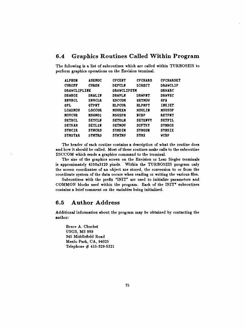
6.4 Graphics Routines Called Within Program
The following is a list of subroutines which are called within TURBOSEIS to perform graphics operations on the Envision terminal.
ALPHONCUROFF
ASKHOCCURON
DRAWCLIPLINEDRWBOXENVBCLGPLLOADMOUMOVCURSETBCLSETKAHSYMCIRSTMSTAR
DRWLINENVCLRGTPHTLOCCURMSGM01SETCLNSETLINSTHCRSSYMTRD
CPCEHTDEFCLN
CPCHARSDIRECT
DRAWCLIPSTNDRWPLNESCCOHHLPCURHOUEXHMSGSPHSETDLNSETMOUSYHDIMSYMTRU
DRWPNTGETHOUHLPMPTHOULINNCBPSETENVYSOFTKYSYHGONSYMX
CPCHARSETDRAVCLIPDRWARCDRWVECGFAINKJETMOUSOPRETPMTSETFILSYMBOXSYMSIXWCBP
The header of each routine contains a description of what the routine does and how it should be called. Most of these routines make calls to the subroutine ESCCOM which sends a graphics command to the terminal.
The size of the graphics screen on the Envision or Lear Siegler terminals is approximately 4150x3120 pixels. Within the TURBOSEIS program only the screen coordinates of an object are stored, the conversion to or from the coordinate system of the data occurs when reading or writing the various files.
Subroutines with the prefix "INIT" are used to initialize parameters and COMMON blocks used within the program. Each of the INIT* subroutines contains a brief comment on the variables being initialized.
6.5 Author Address
Additional information about the program may be obtained by contacting the author:
Bruce A. Chuchel USGS, MS 989 345 Middlefield Road Menlo Park, CA, 94025 Telephone # 415-329-5321
75

Chapter 7
REFERENCES
Ackermann, Hans D., Panktatz, Leroy W., and Dansereau, Danny, 1986, Res olution of ambiguities of seismic icftaction traveltime curves: Geophysics, v. 51, no. 2, p. 223-235.
Ackermann, Hans D., Pankratz, Leroy W., and Dansereau, Danny, 1982, A comprehensive system for interpreting seismic-refraction arrival-time data using interactive computer methods: U.S. Geological Survey Open-File Report 82-1065, 265 p.
Chuchel, Bruce A., 1989, TURBOSEIS - Program Listing: U.S. Geological Sur vey Open-File Report 89-567B, (5 1/4 inch, DOS 2.0 formatted diskette).
Envision Technology, INC., 1983, Models 220 and 230 color graphics terminals reference manual, #20640-1: San Jose, CA, 178 p.
Envision Technology, INC., 1983, Mouse accessory reference manual, #21133- 0\ San Jose, CA, 8 p.
Lear Siegler, INC., 1985, Models 7105 and 7107 Color Graphics Terminals Users Reference Manual: Anaheim, CA, 190 p.
76

Appendix A
Files Used By TURBOSEIS
We list the routines within TURBOSEIS for reading and writing the various files; the reader is referred to Ackermann [Ackermann and others, 1982] for the gory details on the programs and routines for reading and writing their files. Each of the input and output routines in TURBOSEIS describe the format of the material contained in the file. These formats are briefly discussed below.
TURBOSEIS reads a model file with the subroutine REDTURBO, and writes it to a file with the subroutine WRTTURBO. This file is unique to TURBOSEIS, none of the programs of Ackermann [Ackermann and others, 1982] recognize this format. An OTX file is read by the subroutine READ- SEIS. The T-layer file is written with the subroutine WRTLAY.
A.I TURBOSEIS Model Pile Format
The TURBOSEIS model file consists of three basic components. The first sec tion consists of six header records describing various properties about the model, the model's author, date of creation and modification, and the version's of the program used to create and last modify the model. It is of variable format, and the components read by the program are contained between a colon (:) and a semicolon (;).
The second section consists of the coordinate information to describe the different layers. The first line consists of a single record containing the following information.
NTOTAL The total number of coordinate pairs in the model; 16.
KTEMP(20) An array containing the shot point numbers in the model, these numbers are obtained from the OTX file; 12.
77
In TURBOSEIS the FORTRAN statement to read this record is the follow ing; currently NSHTMAX = 20.
Read (iounit,15,err=40,end=70) ntotal, (ktempOO, k=l,nshtmax) IB Format (x,i6,<nshtmax>(x,i2))
In the TURBOSEIS model file, the information for each shot point is sepa rated into the forward and reversed components. For each of these components of the shot point, a record similar to the following is output, followed by its' distance-time coordinate pairs.
NUMSHT Shot point number; 12.
NKSHT Shot point number; 12.
NUMPTS The number of distance-time coordinate pairs for this shot point and direction; 13.
XSD The shot point distance (from OTX file, see the OTX file definition which follows); F12.2.
DSD The shot point depth (also from OTX file); F12.2.
OSD The shot point offset (also from OTX file); F12.2.
In TURBOSEIS the FORTRAN statement to read this record is the follow ing.
Read (iounit,20,err=40,end=70) numsht, nksht, numpts, xsd, ft dsd, osd
20 Format (x,i2,x,i2,x,i3,x,3112.2)
The coordinate pairs containing the layer information (for this shot point and direction) follow this record. They consist of the following:
XLOC The X coordinate for a position; E16.8.
YLOC The Y (time) coordinate for a position; E16.8.
IHRZN The layer (horizon) number assigned to this coordinate pair; 13.
In TURBOSEIS the FORTRAN statement to read this record is the follow ing.
Read (iounit,30,err=40,end=70) xloc, yloc, ihrzn 30 Format (2(x,el6.8),x,i3)
The third section contains the symbol information; one record for each sym bol. These records contain the following information:
78

NUMSYM An integer number of the symbol type. Numbers correspond to the following, 4 = Reciprocal pt, 5 = Intercept pt in reversed direction, 6 = Intercept pt in forward direction; 12.
NSYM1 Shot point number this symbol is associated with; 12.
NLAY The layer number assigned to this symbol; 12.
NSYM2 The shot point along which this symbol is drawn; 12.
YSYM The Y (time) coordinate along the shot point where this symbol is located; E16.8.
In TURBOSEIS the FORTRAN statement to read this record is the following.
Read (iounit,20,err=80,end=90) numsym, nsyml, nlay, nsym2, ysym 20 Format (4(x,i2),x,e!6.8)
Below is a sample TURBOSEIS model file, the lines beginning with "-->" are comment lines inserted here, they are NOT part of the model file.
> Next six lines are the header block. USGS Program: TURBOSEIS; Version: 1.200Technical Contact: Brace A. Chuchel; Release: 1989/APR/12 Model Author: Bans D. Ackermann, USGS, MS 964, Denver, CO, 80225. Created: TEST.XMA; Date: 18-JUN-1987 16:40:36; Model vers: 1 Mod. Author: Tour name here Modified: TEST.1MB; Date: 6-OCT-1989 20:40:05; Model vers: 2
> Next line begins the layer information block.24 13 11 14 12 16 15 17 0 0 0 0 0 0 0 0 0 0 0 0 0
13 13 0 7700.00 45.70 -1.00 13 13 0 7700.00 45.70 -1.00 11 11 0 22143.00 45.70 -1.00 11 11 0 22143.00 45.70 -1.00 14 14 5 0.00 45.70 -1.00-0.11492000E+05 0.28407764E+04 3-0.91993379E+04 0.26610679E+04 3-0.68149668E+04 0.22117966E+04 3-0.48432773E+04 0.16277441E+04 3-0.23519141E+04 0.10436915E+04 3
14 14 2 0.00 45.70 -1.000.21983828E+04 0.79667944E+03 40.87561914E+04 0.26703398E+04 4
12 12 0 13426.00 45.70 -1.00 12 12 0 13426.00 45.70 -1.00 16 16 0 -16512.00 45.70 -1.00 16 16 7 -16512.00 45.70 -1.00
79

-0.15649362E+05 0.55363049E+03 3-0.12007871E+05 0.16142704E+04 3-0.71642188E+04 0.24476301E+04 3-0.21571719E+04 0.34499924E+04 30.12508945E+04 0.39803120E+04 30.13325938E+04 0.39977954E+04 30.51958438E+04 0.47175146E+04 3
15 15 4 -6830.00 45.70 -1.00-0.16642850E+05 0.26610679E+04 3-0.14671158E+05 0.21219424E+04 3-0.11889395E+05 0.15620814E+04 3-0.89089336E+04 0.79832037E+03 3
15 15 6 -6830.00 45.70 -1.00-0.50250742E+04 0.89692358E+03 30.20258086E+04 0.29114614E+04 30.29872930E+04 0.25430422E+04 40.90766875E+04 0.38250208E+04 40.58717422E+04 0.33344458E+04 60.13391035E+05 0.48383052E+04 6
17 17 0 -24412.00 45.70 -1.00 17 17 0 -24412.00 45.70 -1.00 > Next line begins the symbol block. 4136 0.45326587E+04 4336 0.23326592E+04 4631 0.45326587E+04 4633 0.23326592E+04 6231 O.OOOOOOOOE+00 5536 0.21244458E+04 6633 0.25561194E+04 6 10 3 1 0.51244082E+04 6 10 3 3 0.37746060E+04 6 10 3 5 0.45711588E+03 6 10 3 6 0.25561194E+045 11 35 0.25669966E+046 12 3 6 0.25561194E+04
A.2 OTX File Format
An OTX file consists of a record containing shot point location information followed by multiple records of observed distance-time pairs for this shot point. When there is more than one shot point, each shot point location record, and its observed distance-time pairs, follow in succession.
The shot point location record, and format, consists of the following:
80

K Shot point number; 14.
N Number of observed X, T pairs that follow for this shot point; 14.
XS Distance of shot point from some predefined origin; F12.2.
DS Depth of shot; F12.2.
OS Offset distance perpendicular to line. If actual distances are input, this is set to -1; F12.2.
In TURBOSEIS the FORTRAN statement for reading this record is the follow ing:
READ (IDSK,1000,ERR=20,END=30) K, N, XS, DS, OS 1000 FORMAT(2I4, 3F12.2)
The X, T pairs are read in 2F12.2 format. Below is a sample OTX file; the portion of lines with the " " characters, and the trailing text, are comments inserted here.
13 9 7700.00-23232.20 6205.50-22402.20-22018.20-21620.20-20837.20-20056.20-19269.20-18903.20-18487.20
11 12point
-2787.10-2056.10-863.10-420.10-62.10171.90523.90835.901225.901980.902366.903093.90
6125.526048.335980.005871.675781.675631.675581.665496.67
22143.00
5051.694904.704759.034684.694614.084546.604487.534429.384363.194271.014201.354081.78
45.70 -1.00 Shot point info X, T pair
45.70 -1.00 Another shot
X, T pair
81

A.3 T-layer File Format
This file is identical in format to the OTX file described in the previous section.
82