TurboCAD Deluxe V16.2 Caboose SAMPLE - Textual … Deluxe V16.2 Caboose SAMPLE.pdf · based on such...
25
Donald B. Cheke www.textualcreations.ca 1 TurboCAD Deluxe V16.2 – Caboose Donald B. Cheke
Transcript of TurboCAD Deluxe V16.2 Caboose SAMPLE - Textual … Deluxe V16.2 Caboose SAMPLE.pdf · based on such...

Donald B. Cheke www.textualcreations.ca
1
TurboCAD Deluxe V16.2 – Caboose
Donald B. Cheke

Donald B. Cheke
Copyright © 2010 Donald B. Cheke
All rights reserved No part of this document may be reproduced, copied, stored on a retrieval system or transmitted in any form without written permission from the author. The purchaser may, however, print one copy of the document to paper and may make one backup copy of the keeping. Limitation of Liability While every effort has been taken in the preparation and the writing of this document the author assumes no responsibility for errors and/or omissions nor for the uses of the materialbased on such use. No warranties are made, express or implied with regard to either the contents of the document, its merchant ability or fitness for a particular purpose. The author should not be liable for direct, indirect, special, incidental or consequential damages arising out of the use or inability to use the contents of this document. Special Note All of the work presented within this tutorprevious versions are welcome to try the tutorial it cannot be stated what results will be achieved. Many changes, some subtle and others not so subtle, are made with each program revision. Although many steps and directions would be generic some may not be. The same can be said for toolsversions. Older versions may not have the same tools as the tools themselves may have been revised and hence, work in a different manner than they previously did.
2
TurboCAD is a registered trademark of
Saskatoon
Visit: www.textualcreations.ca
No part of this document may be reproduced, copied, stored on a retrieval system or transmitted in any form without written permission from the author. The purchaser may, however, print one copy of the document to paper and may make one backup copy of the downloaded material for personal
While every effort has been taken in the preparation and the writing of this document the author assumes no responsibility for errors and/or omissions nor for the uses of the materialbased on such use. No warranties are made, express or implied with regard to either the contents of the document, its merchant ability or fitness for a particular purpose. The author should not be liable for
cidental or consequential damages arising out of the use or inability to use the
All of the work presented within this tutorial is based on TurboCAD Deluxe V16try the tutorial it cannot be stated what results will be achieved. Many
changes, some subtle and others not so subtle, are made with each program revision. Although many steps and directions would be generic some may not be. The same can be said for tools
have the same tools as Deluxe V16.2 and if the same tools are available the tools themselves may have been revised and hence, work in a different manner than they previously
www.textualcreations.ca
TurboCAD is a registered trademark of IMSI/Design.
Published by:
Donald B. Cheke Saskatoon, SK Canada
www.textualcreations.ca
No part of this document may be reproduced, copied, stored on a retrieval system or transmitted in any form without written permission from the author. The purchaser may, however, print one copy of the
downloaded material for personal safe
While every effort has been taken in the preparation and the writing of this document the author assumes no responsibility for errors and/or omissions nor for the uses of the material and the decisions based on such use. No warranties are made, express or implied with regard to either the contents of the document, its merchant ability or fitness for a particular purpose. The author should not be liable for
cidental or consequential damages arising out of the use or inability to use the
V16.2. Although users of try the tutorial it cannot be stated what results will be achieved. Many
changes, some subtle and others not so subtle, are made with each program revision. Although many steps and directions would be generic some may not be. The same can be said for tools between
and if the same tools are available the tools themselves may have been revised and hence, work in a different manner than they previously

Donald B. Cheke www.textualcreations.ca
3
Table of Contents Table of Contents ......................................................................................................................................................... 3 Introduction .................................................................................................................................................................. 4 Setup .............................................................................................................................................................................. 6 Initial Lighting ............................................................................................................................................................. 13 2D Wheel, Hub and Track Profiles .......................................................................................................................... 18 3D Wheels and Hubs ................................................................................................................................................. 35 2D Wheel Carriage Profiles ...................................................................................................................................... 37 3D Wheel Carriage .................................................................................................................................................... 58 2D Bolster Profile to 3D Bolster .............................................................................................................................. 73 3D Axels ...................................................................................................................................................................... 80 2D Main Car Profiles ................................................................................................................................................. 85 3D Main Car ................................................................................................................................................................ 96 2D Car End Entry ..................................................................................................................................................... 106 3D Car End Entry ..................................................................................................................................................... 114 3D Windows & Widow Frames ............................................................................................................................. 117 End Gear – 2D/3D Stairs ....................................................................................................................................... 125 End Gear – 2D/3D Wheel Brake .......................................................................................................................... 139 End Gear – 2D/3D Ladder .................................................................................................................................... 154 End Gear – 2D/3D Hand Rail ............................................................................................................................... 160 End Gear – 2D/3D Coupler ................................................................................................................................... 163 Car Side Windows ................................................................................................................................................... 176 Far End Components .............................................................................................................................................. 185 2D Cupola Profiles .................................................................................................................................................. 188 3D Cupola ................................................................................................................................................................ 192 Cupola Windows ..................................................................................................................................................... 199 2D/3D Chimney ...................................................................................................................................................... 205 Signage ..................................................................................................................................................................... 210 Panel Ribs ................................................................................................................................................................ 215 3D Track ................................................................................................................................................................... 220 Materials Application ............................................................................................................................................. 223 Ground Plane (Shadow Catcher) .......................................................................................................................... 242 Named Views ........................................................................................................................................................... 244 Render Scene Luminance ..................................................................................................................................... 249 Render Scene Environment .................................................................................................................................. 252 Saving the Rendered Image.................................................................................................................................. 255

Donald B. Cheke www.textualcreations.ca
4
Introduction There is something romantic about the Caboose. It conjures up all kinds of feeling about the past, about solitude and life on the rails. Many folks have a fascination with railroading and the author is no exception, so a tutorial to create such a thing seemed the perfect way to introduce new users to TurboCAD. An HO scale wide vision Caboose, purchased from the local hobby store, will be used as the basis of the tutorial. The reader is not required to purchase one, as the author will measure and provide the required dimensions.
Digital calipers with the model. Within this very comprehensive tutorial the reader will be led through each keystroke to produce all components of the caboose and track that is illustrated on the cover of the tutorial. The reader will learn how to create each object by manipulating 2D profiles and 3D primitive shapes. The reader will learn how to set up their drawing, how to insert standard lighting and how utilize render scene luminance. The reader will learn how to establish a render scene environment and the reader will learn how to render their drawing and save it in a high resolution image format. This tutorial is in no way intended to teach mechanical design but rather it is intended to teach the use of some of the tools that TurboCAD has to offer and to introduce the new user to a drawing methodology. The author feels confident that the techniques outlined within the tutorial can help lay the foundation for future successful TurboCAD drawing and illustration for even the newest user. As with any technically advanced software, the user is generally faced with a steep learning curve. It is the hope of the author that the money and time spent working through a Textual Creations tutorial will help ease the learning and allow the reader to come away feeling confident that they made a wise decision. This tutorial will assume that the reader has TurboCAD Deluxe V16.2. There are many ways to approach a project and it is likely that each person using the program would proceed in very different ways, so be open to alternative methods as experience builds. What is important is that the user becomes familiar with the objects that they wish to model and begin to look at them in a different way than they might otherwise do. What primitive shapes make up the whole? What will be required of these primitive shapes early in the drawing and how will this affect needs further along? What component or components should be started with? Many questions can only be answered through experience, but hopefully some of them will be answered by the time the beginner has worked through this tutorial. There is a great deal covered in this tutorial and the author urges the beginner to be
Donald B. Cheke www.textualcreations.ca
5
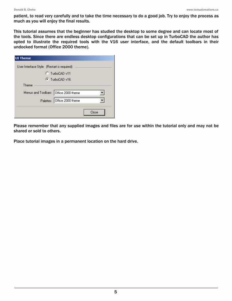
patient, to read very carefully and to take the time necessary to do a good job. Try to enjoy the process as much as you will enjoy the final results. This tutorial assumes that the beginner has studied the desktop to some degree and can locate most of the tools. Since there are endless desktop configurations that can be set up in TurboCAD the author has opted to illustrate the required tools with the V16 user interface, and the default toolbars in their undocked format (Office 2000 theme).
Please remember that any supplied images and files are for use within the tutorial only and may not be shared or sold to others. Place tutorial images in a permanent location on the hard drive.

Donald B. Cheke www.textualcreations.ca
35
Press the Space Bar to exit the tool. Select the hub and wheel profiles. Tab into the Inspector Bar and enter -.5 in the Delta Y field. Press Enter.
Press Ctrl + A to select all the components in the drawing. From the Format menu at the top of the TurboCAD desktop select Place on Workplane. With the 2D components still selected, select Blue from the color dropdown menu on the Property toolbar.
3D Wheels and Hubs The wheel, hub and half spike profiles will now be revolved into 3D objects so that they will be fully visible when the view is changed and work continues on the 2D profiles of the wheel carriage. Select the Revolve tool from the 3D Object toolbar.
Right mouse click on the Revolve tool icon to open the Properties dialogue for the tool. Under the TC Surface Options tab enter 90 in the two Surface Options fields. Click OK.

Donald B. Cheke www.textualcreations.ca
36
Select the half wheel profile as the object to revolve. (In case the reader has not noticed, TurboCAD provides helpful instructions on the status bar while drawings.)
V SEKE snap the top left corner of the half hub profile to define the first point of the revolve axis. Move the cursor to the opposite side of the half hub profile and V SEKE snap to define the second point of the revolve axis. In progress below.
Select the half hub profile as the next object to revolve. V SEKE snap the top right corner of the half hub profile to define the first point of the revolve axis. Press and hold the Shift key down. Move the cursor to the right a short distance and then left mouse click to define the second point of the revolve axis. Release the Shift key. In progress below.
Donald B. Cheke www.textualcreations.ca
37
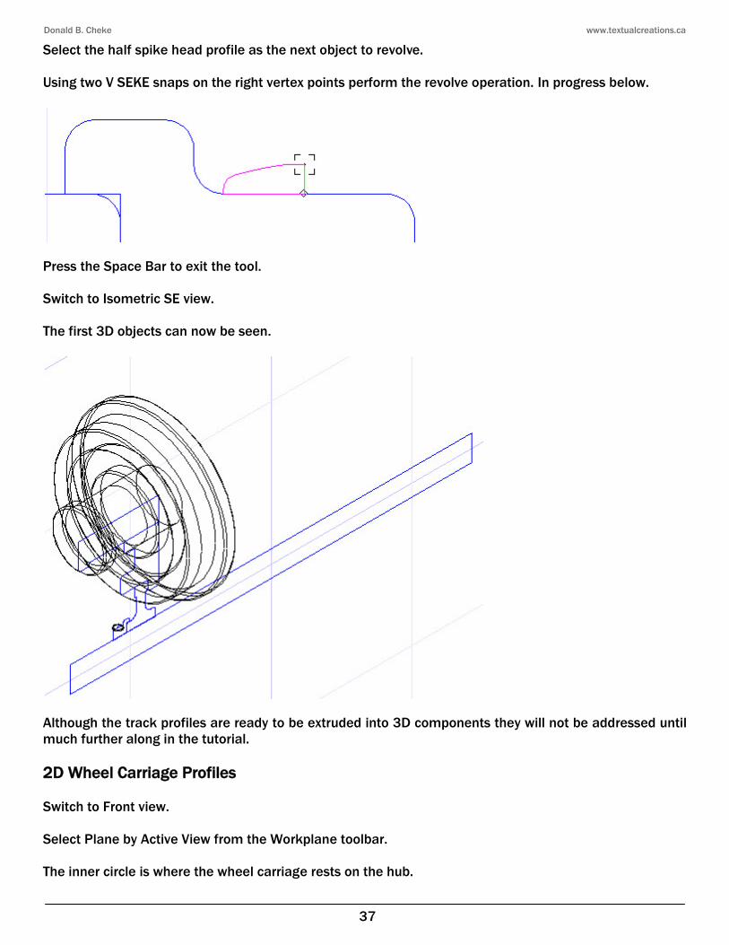
Select the half spike head profile as the next object to revolve. Using two V SEKE snaps on the right vertex points perform the revolve operation. In progress below.
Press the Space Bar to exit the tool. Switch to Isometric SE view. The first 3D objects can now be seen.
Although the track profiles are ready to be extruded into 3D components they will not be addressed until much further along in the tutorial. 2D Wheel Carriage Profiles Switch to Front view. Select Plane by Active View from the Workplane toolbar. The inner circle is where the wheel carriage rests on the hub.

Donald B. Cheke www.textualcreations.ca
71
Press and hold the Shift key down. Deselect the frame/coils block by left mouse clicking it and select the other wheel/hub block by left mouse clicking it. Release the Shift key. Select the Mirror Copy tool from the Copy toolbar. V SEKE snap the top vertex of the small line at the center of the frame/coils block to define the first point of the mirroring line. Press and hold the Shift key down. Move the cursor upward a short distance and then left mouse click to define the second point of the mirroring line. Release the Shift key. In progress below.
Press Esc to deselect the selection. Switch to Isometric SE view. Some layers will now be created to help organize the drawing and make working with it a bit easier. Open the Design Director palette. Select the Create New icon at the top of the Design Director palette to create a new layer.

Donald B. Cheke www.textualcreations.ca
72
Type 2D in the Layer name field and click OK or press Enter.
In the same manner create two more layers called Wheel & Hub and Wheel Carriage. Turn off the new layers by left mouse clicking the eyes icons that correspond to the new layers. Please note that layer 0 should remain visible at all times as the program uses this layer for internal processes.
Select the four wheel & hub blocks and then assign them to the Wheel & Hub layer by left mouse clicking the clear box to the right of the Wheel & Hub layer name on the Design Director palette. A green arrow will appear indicating that the procedure was done and the selection will disappear as the layer is not visible.
Alternately objects can be assigned to their layers via the Properties toolbar at the top of the TurboCAD desktop. Select the two frame/coils blocks in the drawing. From the Layer dropdown menu on the Property toolbar select Wheel Carriage. In progress below.

Donald B. Cheke www.textualcreations.ca
73
Press Ctrl + A to select the rest of the objects in the drawing. In the same manner as above, assign the selection to the 2D layer.
Turn on the 3D layers (Wheel & Hub and Wheel Carriage).
2D Bolster Profile to 3D Bolster A simple Bolster will now be created. Switch to World Plan view. Select the Line tool from the Line toolbar. Using two V SEKE snaps place a line at the inside center between of the two frames, as indicated in the picture below.

Donald B. Cheke www.textualcreations.ca
96
Select the Mirror Copy tool from the Copy toolbar. Switch to World Plan view. Select Plane by World from the Workplane toolbar. M SEKE snap the first point of the mirroring line to the middle of the blue line. Press and hold the Shift key down. Move the cursor upward a short distance and left mouse click to define the second point of the mirroring line. Release the Shift key. In progress below.
3D Main Car Switch to Isometric SE view. Turn on the 2D layer. Press Ctrl + A to select all the components in the drawing. Press D SEKE and relocate (M SEKE) the reference point to the middle of the blue line that runs between the two wheel carriages. Tab into the Inspector Bar and enter 0 in the X Position field. Press Enter.

Donald B. Cheke www.textualcreations.ca
97
Press Esc to deselect the selection. Select Refresh at the top of the Design Director palette or left mouse click below the highlighted names or all selected layers will be turned off, en masse, in the next set. Turn off all layers, except layer 0. Right mouse click and ensure that Open Window mode is engaged. If it is not, select it. Select the 2D profiles of the car as indicated in the picture below.
Tab into the Inspector Bar and enter 0 in the X Position field. Press Enter.
The car is now central in the drawing and this will make positioning some of the components a bit easier as the tutorial progresses. Select the Simple Extrude tool from the 3D Object toolbar. Select the Two sided extrude option.
Select the floor profile as the object to extrude. Tab into the Inspector Bar and enter 61 in the Height field. Press Enter to extrude 61 mm in each direction.

Donald B. Cheke www.textualcreations.ca
135
Move the cursor to the opposite back corner of the opening and V SEKE snap a copy in place. In progress below.
Press Esc to exit the Rubber Stamp tool or left mouse click the red X (Cancel) on the Inspector Bar to quit using the Rubber Stamp tool. Press Esc to deselect the selection. Select the Workplane by Facet tool from the Workplane toolbar. Place the cursor over the inner face of the right side panel, as indicated in the picture below, and when the facet is highlighted left mouse click to define the workplane.
Select the steps profile and then select Place on Workplane from the Format menu at the top of the TurboCAD desktop. Select the Simple Extrude tool from the 3D Object toolbar. Select the steps profile as the object to extrude. Move the cursor to the opposite lower inside corner, as indicated in the picture below, and V SEKE snap to define the extent of the extrusion. In progress below.

Donald B. Cheke www.textualcreations.ca
136
Press Ctrl + K to open the Select by Colors dialogue. Select Blue and Red and then click OK. Assign the selection to the 2D layer. Create a new layer called Stairs.
Select the three stair components and assign them to the Stairs layer. Leave them selected. The stairs will now be mirror copied to the opposite side at the back. Select Plane by World from the Workplane toolbar. Select the Mirror Copy tool from the Copy toolbar. Switch to World Plan view. Zoom in very close to the middle of the back floor area and V SEKE snap to define the first point of the mirroring line. Press and hold the Shift key down. Move the cursor to the right a short distance and then left mouse click to define the second point of the mirroring line. Release the Shift key. In progress below.
Switch to Isometric SW view. Press Ctrl + A to select all of the objects in the drawing area. Select the Hidden Line render tool on the Render toolbar to have a look so far at the back end.
Press Esc to deselect the selection.

Donald B. Cheke www.textualcreations.ca
137
The floor needs to have two small boxes added to the ends.
Select the Wireframe tool render toolbar to end the render. Select the Box tool from the 3D Object toolbar. Using three V SEKE snaps place a box on the right side as indicated in the pictures below. First V SEKE snap.
Second V SEKE snap.

Donald B. Cheke www.textualcreations.ca
153
Create a new layer called Wheel Brake and turn it off.
Select and assign all the visible components to the new layer. Turn on the Roof, Floor and Wheel Brake layers. Switch to Isometric NE view. Press Ctrl + L to open the Select by Layer dialogue. Select Wheel Brake and click OK.
With the wheel brake still selected, Tab into the Inspector Bar and enter 6.455 in the Delta Y field. Press Enter.
Press Esc to deselect the selection.

Donald B. Cheke www.textualcreations.ca
154
End Gear – 2D/3D Ladder The ladder will now be constructed. Turn on the Platform layer. Switch to Front view. Select Plane by Active View from the Workplane toolbar. Select the Polyline tool from the Line toolbar. V SEKE snap the first point of the polyline to the lower left corner of the floor. Tab into the Inspector Bar and enter 33 in the Length field and 90 in the Angle field. Press Enter.
Tab into the Inspector Bar and enter 2 in the Length field and 0 in the Angle field. Press Enter.
Tab into the Inspector Bar and enter 5 in the Length field and 288 in the Angle field. Press Enter.
Select Finish. Select the Fillet tool from the Modify toolbar. Tab into the Inspector Bar and enter 1 in the Radius field. Press Enter.
Using left mouse clicks on the lines that comprise the corners, fillet the top two corners of the ladder profile.

Donald B. Cheke www.textualcreations.ca
186
Left mouse click a copy in a clear area of the drawing, well away from the original. In progress below.
Press Esc to exit the Rubber Stamp tool. Select all the components of the stamp copied set. Press D SEKE and relocate (V SEKE) the reference point to the top corner of the platform as indicated in the picture below.
Tab into the Inspector Bar and enter 180 in the Z Rotation field. Press Enter.
Left mouse click on the reference point of the selection to pick it up. Move the cursor to the corresponding vertex on the platform of the other half car, as indicated in the picture below, and V SEKE snap the selection in place. In progress below.
Donald B. Cheke www.textualcreations.ca
187
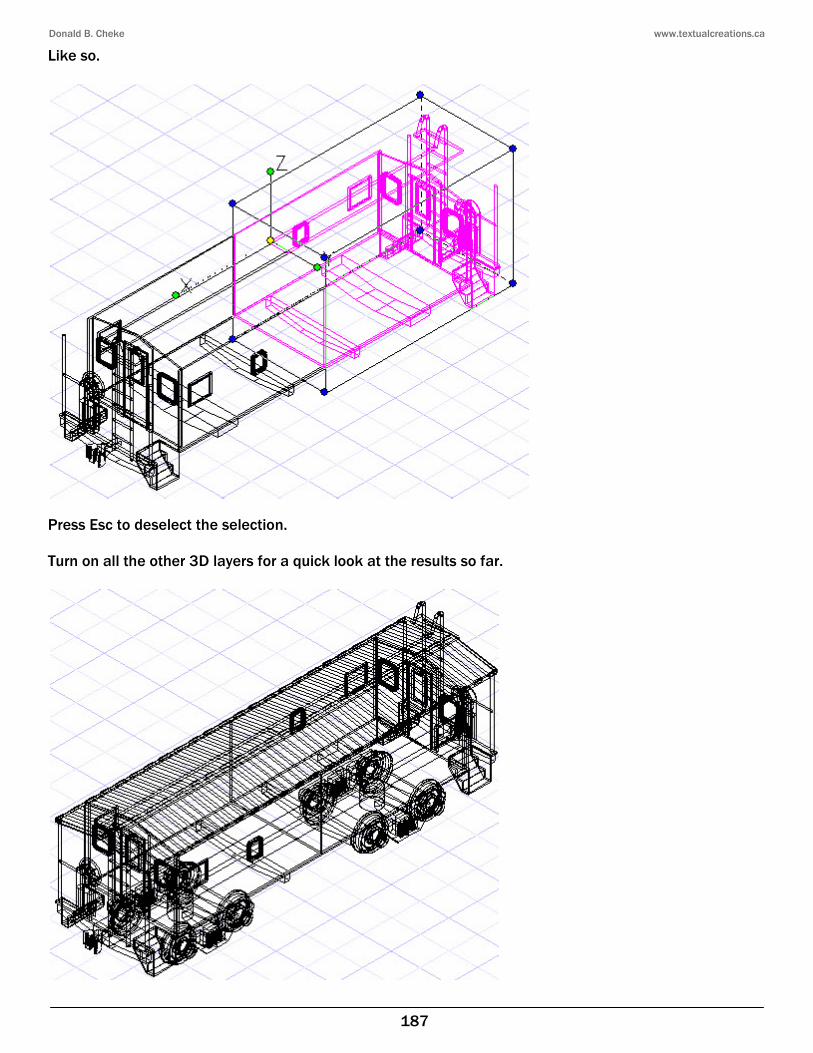
Like so.
Press Esc to deselect the selection. Turn on all the other 3D layers for a quick look at the results so far.

Donald B. Cheke www.textualcreations.ca
233
Press Ctrl + A to select all the visible objects. Select Quality Rendering tool on the Render toolbar. Allow the screen to render and then press Esc to deselect the selection.
Select the Wireframe tool to end the render. Turn off the three 3D layers and then turn on the layers as illustrated below.

Donald B. Cheke www.textualcreations.ca
242
Select the Wireframe tool to end the render. Turn off the 3D layers and then turn on the Ties layer. Ground Plane (Shadow Catcher) It is now time to create a shadow catcher. Select the Box tool from the 3D Object toolbar. V SEKE snap the lower left corner of the first tie to place the first point of the rectangle. Move the cursor to the right for a short distance and then Tab into the Inspector Bar and enter 400 in the Width field, 400 in the Length field and -.002 in the Height field. Press Enter.
Press the Space Bar to exit the tool. Select the box. Tab into then Inspector Bar and enter -50 in the X Position and 70 in the Y Position field. Press Enter.
Create a new layer called Ground Plane.
Assign the selection to the new layer. Double click on the ground plane rectangle to open the Properties dialogue. Under the 3D tab select Edit Material.
Left mouse click the yellow folder by the Category dropdown menu to create a new category. Enter Shadow Catcher in the Name field of the New Category dialogue that opens and click OK.
Donald B. Cheke www.textualcreations.ca
251
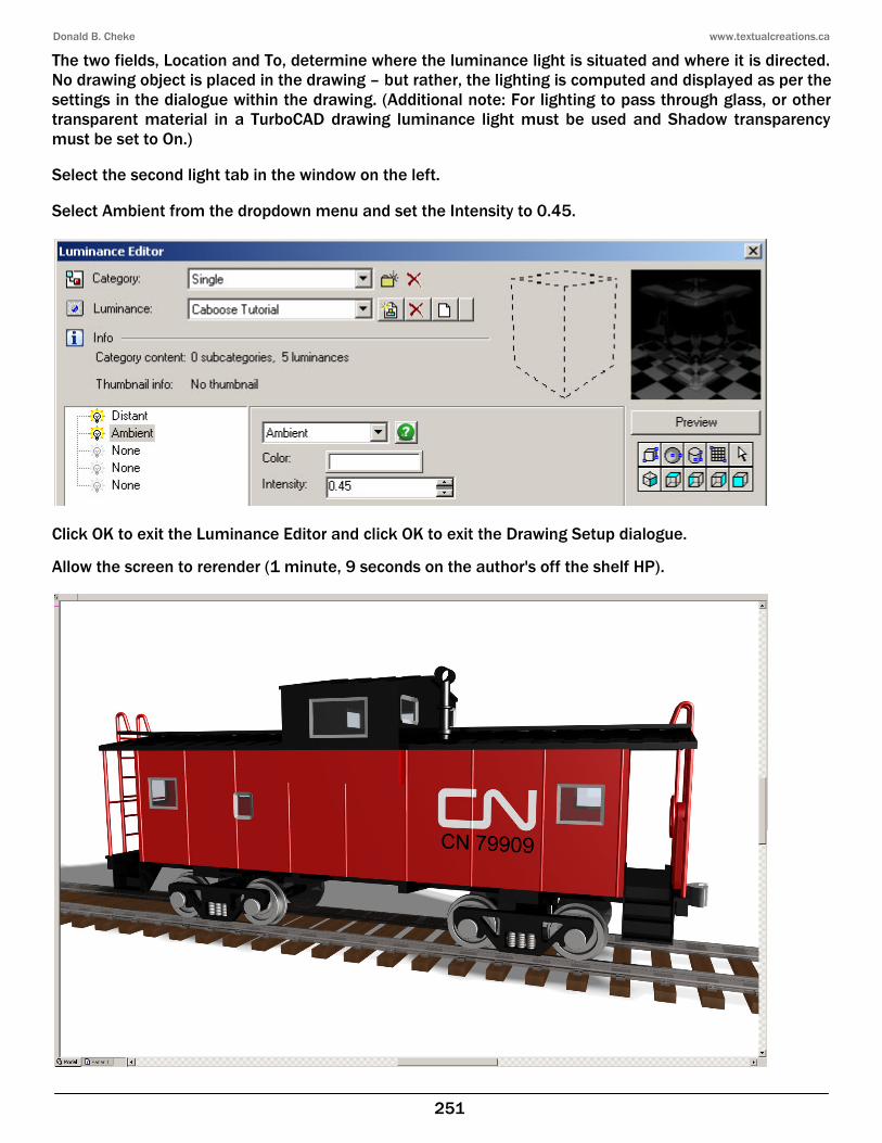
The two fields, Location and To, determine where the luminance light is situated and where it is directed. No drawing object is placed in the drawing – but rather, the lighting is computed and displayed as per the settings in the dialogue within the drawing. (Additional note: For lighting to pass through glass, or other transparent material in a TurboCAD drawing luminance light must be used and Shadow transparency must be set to On.) Select the second light tab in the window on the left. Select Ambient from the dropdown menu and set the Intensity to 0.45.
Click OK to exit the Luminance Editor and click OK to exit the Drawing Setup dialogue. Allow the screen to rerender (1 minute, 9 seconds on the author's off the shelf HP).

Donald B. Cheke www.textualcreations.ca
252
Render Scene Environment At this point a Ray Cube background will be established as an environment. From the Options menu at the top of the TurboCAD desktop select Render Scene Environment.
Select Graduated from the Environment dropdown menu. Select Edit Environment.
Select the Create New Category icon to the right of the current environment name field. Enter IBL (Image Based Lighting) in the New Category dialogue and click OK.
Select the Create New Environment icon to the right of the current environment name field. Enter Caboose Tutorial in the New Environment dialogue and click OK.

Donald B. Cheke www.textualcreations.ca
255
Click OK to exit the Render Scene Environment Editor and click OK to exit the Drawing Setup dialogue. Allow the scene to rerender (1 minute, 7 seconds on the author's off the shelf HP).
Saving the Rendered Image This render will now be saved.