Tunnel Lainz 12 km of Urban Tunnelling Construction Lot LT44
10
1st International Congress on Tunnels andUunderground Structures in South-East Europe „USING UNDERGROUND SPACE“ April 7-9, 2011, Dubrovnik, Croatia Tunnel Lainz – 12 km of Urban Tunnelling – Construction Lot LT44 Josef DALLER, iC consulenten ZT GesmbH, Austria, [email protected] Michael PROPRENTER, iC consulenten ZT GesmbH, Austria, [email protected] Summary The project Tunnel Lainz will improve the connection between the western, southern and eastern railway lines in Vienna. Construction of the tunnels commenced in the year of 2000 and the opening for the traffic of the entire project is scheduled for 2012. The major part of the Tunnel Lainz of about 12 km will be situated underground. Various structures such as single or double track tubes, pillar galleries, widening sections or large structures for switches and changeovers are included. The safety concept requires galleries, adits and shafts for emergency purposes. The current paper focuses on the construction lot LT 44, which provides the connection to the southern and eastern railway lines around Vienna. Keywords: Tunnel, railway, urban environment, soft ground 1. Introduction An increase of the current capacity of the main railway axes crossing Vienna is an essential concern both at the national and the European level. The project Tunnel Lainz will improve the connection between the western, southern and eastern railway lines in and around the city of Vienna, which is inevitable with respect to the increasing demand regarding the passenger and freight transport. Construction of the tunnels commenced in 2000 and the opening for the traffic of the entire project is scheduled for 2012. Tunnel Lainz forms together with the adjacent project Wienerwald Tunnel a system of a total length of app. 26 km. The length of the project Tunnel Lainz is around 13 km, whereof the major part of about 12 km is situated underground. Two thirds of the tunnels are carried out by mined tunnelling method and the remaining section is placed in cut&cover tunnels. The entire scheme is divided into different construction lots, which are based on the type of construction and logistic optimization to minimize the impact on the surroundings during the construction. Various underground structures such as single or double track tubes, pillar galleries, widening sections or large structures for switches and changeovers are included. In addition, the safety concept requires galleries or adits and shafts of variable lengths and depths for emergency purposes. A considerable section of the alignment has to underpass residential areas, business districts or major traffic infrastructure with shallow overburden, where strict limiting values for settlements were specified in the building permission documents. To the contrary, other segments had to cross sheared zones with an overburden of up to 115 m. The aim of the entire project is to provide a state of the art and efficient railway connection under Vienna. Furthermore, the freight train frequency on the existing surface line shall be limited to reduce the noise impact on the residential areas and to provide the possibility for an increase of the local passenger train traffic. The current paper covers the mined tunnel sections of the construction lot LT 44 in the south- eastern part of Vienna. 2. Location
Transcript of Tunnel Lainz 12 km of Urban Tunnelling Construction Lot LT44

1st International Congress on Tunnels andUunderground Structures in South-East Europe „USING UNDERGROUND SPACE“
April 7-9, 2011, Dubrovnik, Croatia
Tunnel Lainz – 12 km of Urban Tunnelling – Construction Lot LT44
Josef DALLER, iC consulenten ZT GesmbH, Austria, [email protected] Michael PROPRENTER, iC consulenten ZT GesmbH, Austria, [email protected]
Summary The project Tunnel Lainz will improve the connection between the western, southern and eastern railway lines in Vienna. Construction of the tunnels commenced in the year of 2000 and the opening for the traffic of the entire project is scheduled for 2012. The major part of the Tunnel Lainz of about 12 km will be situated underground. Various structures such as single or double track tubes, pillar galleries, widening sections or large structures for switches and changeovers are included. The safety concept requires galleries, adits and shafts for emergency purposes. The current paper focuses on the construction lot LT 44, which provides the connection to the southern and eastern railway lines around Vienna.
Keywords: Tunnel, railway, urban environment, soft ground
1. Introduction An increase of the current capacity of the main railway axes crossing Vienna is an essential concern both at the national and the European level. The project Tunnel Lainz will improve the connection between the western, southern and eastern railway lines in and around the city of Vienna, which is inevitable with respect to the increasing demand regarding the passenger and freight transport. Construction of the tunnels commenced in 2000 and the opening for the traffic of the entire project is scheduled for 2012. Tunnel Lainz forms together with the adjacent project Wienerwald Tunnel a system of a total length of app. 26 km. The length of the project Tunnel Lainz is around 13 km, whereof the major part of about 12 km is situated underground. Two thirds of the tunnels are carried out by mined tunnelling method and the remaining section is placed in cut&cover tunnels. The entire scheme is divided into different construction lots, which are based on the type of construction and logistic optimization to minimize the impact on the surroundings during the construction. Various underground structures such as single or double track tubes, pillar galleries, widening sections or large structures for switches and changeovers are included. In addition, the safety concept requires galleries or adits and shafts of variable lengths and depths for emergency purposes. A considerable section of the alignment has to underpass residential areas, business districts or major traffic infrastructure with shallow overburden, where strict limiting values for settlements were specified in the building permission documents. To the contrary, other segments had to cross sheared zones with an overburden of up to 115 m. The aim of the entire project is to provide a state of the art and efficient railway connection under Vienna. Furthermore, the freight train frequency on the existing surface line shall be limited to reduce the noise impact on the residential areas and to provide the possibility for an increase of the local passenger train traffic. The current paper covers the mined tunnel sections of the construction lot LT 44 in the south-eastern part of Vienna.
2. Location
1st International Congress on Tunnels andUunderground Structures in South-East Europe „USING UNDERGROUND SPACE“
April 7-9, 2011, Dubrovnik, Croatia
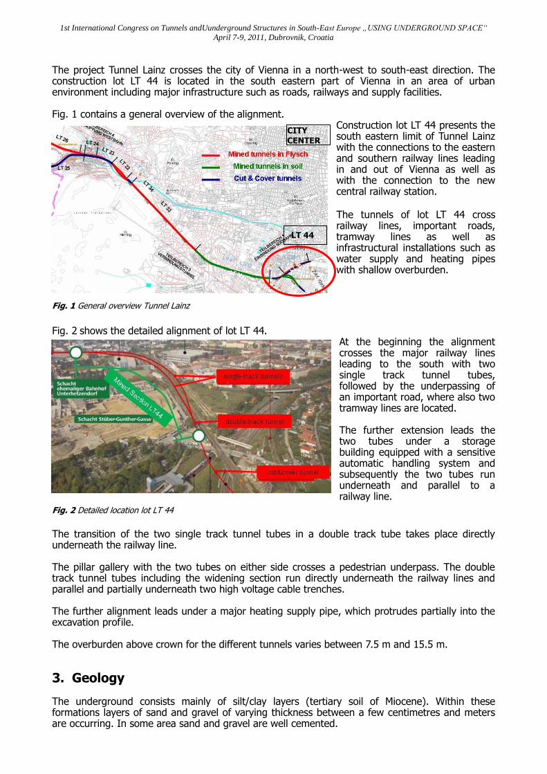
The project Tunnel Lainz crosses the city of Vienna in a north-west to south-east direction. The construction lot LT 44 is located in the south eastern part of Vienna in an area of urban environment including major infrastructure such as roads, railways and supply facilities. Fig. 1 contains a general overview of the alignment.
Construction lot LT 44 presents the south eastern limit of Tunnel Lainz with the connections to the eastern and southern railway lines leading in and out of Vienna as well as with the connection to the new central railway station. The tunnels of lot LT 44 cross railway lines, important roads, tramway lines as well as infrastructural installations such as water supply and heating pipes with shallow overburden.
Fig. 1 General overview Tunnel Lainz
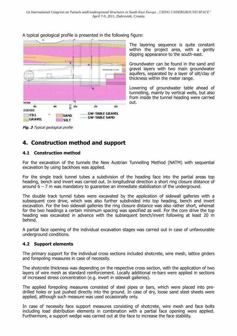
Fig. 2 shows the detailed alignment of lot LT 44.
At the beginning the alignment crosses the major railway lines leading to the south with two single track tunnel tubes, followed by the underpassing of an important road, where also two tramway lines are located. The further extension leads the two tubes under a storage building equipped with a sensitive automatic handling system and subsequently the two tubes run underneath and parallel to a railway line.
Fig. 2 Detailed location lot LT 44
The transition of the two single track tunnel tubes in a double track tube takes place directly underneath the railway line. The pillar gallery with the two tubes on either side crosses a pedestrian underpass. The double track tunnel tubes including the widening section run directly underneath the railway lines and parallel and partially underneath two high voltage cable trenches. The further alignment leads under a major heating supply pipe, which protrudes partially into the excavation profile. The overburden above crown for the different tunnels varies between 7.5 m and 15.5 m.
3. Geology The underground consists mainly of silt/clay layers (tertiary soil of Miocene). Within these formations layers of sand and gravel of varying thickness between a few centimetres and meters are occurring. In some area sand and gravel are well cemented.
LT 44
CITY CENTER
1st International Congress on Tunnels andUunderground Structures in South-East Europe „USING UNDERGROUND SPACE“
April 7-9, 2011, Dubrovnik, Croatia
A typical geological profile is presented in the following figure:
The layering sequence is quite constant within the project area, with a gently dipping appearance to the south-east. Groundwater can be found in the sand and gravel layers with two main groundwater aquifers, separated by a layer of silt/clay of thickness within the meter range. Lowering of groundwater table ahead of tunnelling, mainly by vertical wells, but also from inside the tunnel heading were carried out.
Fig. 3 Typical geological profile
4. Construction method and support 4.1 Construction method For the excavation of the tunnels the New Austrian Tunnelling Method (NATM) with sequential excavation by using backhoes was applied. For the single track tunnel tubes a subdivision of the heading face into the partial areas top heading, bench and invert was carried out. In longitudinal direction a short ring closure distance of around 6 – 7 m was mandatory to guarantee an immediate stabilization of the underground. The double track tunnel tubes were excavated by the application of sidewall galleries with a subsequent core drive, which was also further subdivided into top heading, bench and invert excavation. For the two sidewall galleries the ring closure distance was also rather short, whereat for the two headings a certain minimum spacing was specified as well. For the core drive the top heading was excavated in advance with the subsequent bench/invert following at least 20 m behind. A partial face opening of the individual excavation stages was carried out in case of unfavourable underground conditions. 4.2 Support elements The primary support for the individual cross sections included shotcrete, wire mesh, lattice girders and forepoling measures in case of necessity. The shotcrete thickness was depending on the respective cross section, with the application of two layers of wire mesh as standard reinforcement. Locally additional re-bars were applied in sections of increased stress concentration (e.g. invert in sidewall galleries). The applied forepoling measures consisted of steel pipes or bars, which were placed into pre-drilled holes or just pushed directly into the ground. In case of dry, loose sand steel sheets were applied, although such measure was used occasionally only. In case of necessity face support measures consisting of shotcrete, wire mesh and face bolts including load distribution elements in combination with a partial face opening were applied. Furthermore, a support wedge was carried out at the face to increase the face stability.
1st International Congress on Tunnels andUunderground Structures in South-East Europe „USING UNDERGROUND SPACE“
April 7-9, 2011, Dubrovnik, Croatia
INVERT ARCH
INNER LINING
SHOTCRETE
The application of a pipe roof was originally foreseen in the design for the crossing of major railway lines and roads. The installation could be omitted due to the positive performance of the forepoling measures described before and the low settlements triggered by the excavation.
5. Structures Along its alignment construction lot LT 44 consists of various underground structures including the following:
o Single track tunnel tubes o Double track tunnel tube o Widening sections at transition single double track tubes o Pillar gallery o Emergency shafts o Emergency galleries
The total length of the various mined tunnel sections results in app. 1.5 km, where around 1.2 km are single track tubes. The remaining length is divided into the double track tube including the widening section of about 240 m and 90 m of pillar gallery. A detailed description of the individual structures will be given in the following chapters of this paper. 5.1 Running tunnel 5.1.1 Single track tunnel tubes
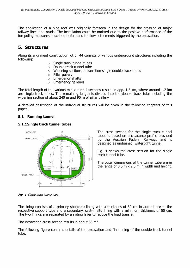
The cross section for the single track tunnel tubes is based on a clearance profile provided by the Austrian Federal Railways and is designed as undrained, watertight tunnel. Fig. 4 shows the cross section for the single track tunnel tube. The outer dimensions of the tunnel tube are in the range of 8.5 m x 9.5 m in width and height.
Fig. 4 Single track tunnel tube
The lining consists of a primary shotcrete lining with a thickness of 30 cm in accordance to the respective support type and a secondary, cast-in situ lining with a minimum thickness of 50 cm. The two linings are separated by a sliding layer to reduce the load transfer. The excavation cross section results in about 85 m². The following figure contains details of the excavation and final lining of the double track tunnel tube.

1st International Congress on Tunnels andUunderground Structures in South-East Europe „USING UNDERGROUND SPACE“
April 7-9, 2011, Dubrovnik, Croatia
SHOTCRETE
INNER LINING
INVERT ARCH
FILL CONCRETE
CONCRETE PILLAR
Fig. 5 Single track tunnel tube – Excavation and final lining
5.1.2 Pillar gallery The pillar gallery provides the transition from two single track tunnel tubes to one double track tunnel tube. After construction of the gallery and execution of the concrete pillar the two single track tubes were excavated on either side of the pillar, which acts as a bearing for the outer lining of the inner sidewalls. The following figure shows the typical profile for the section of maximum width for the pillar gallery.
Over its extension of around 90 m the width of the pillar varies between 1.15 m and 3.6 m to increase the spacing between the axes of the two single track tunnel tubes. The shotcrete thickness for the primary lining of the running tunnels is 35 cm, whereat the thickness for the pillar gallery is 30 cm. The inner lining is designed with 50 cm.
Fig. 6 Pillar gallery with running tunnels
The complete width of the pillar gallery including the two single track tunnel tubes is around 20 m. The excavation cross section for the pillar gallery is about 89 m², with a remaining area around of 50 m² for two the running tunnels. The following figure contains details of the excavation and final lining of the double track tunnel tube.
1st International Congress on Tunnels andUunderground Structures in South-East Europe „USING UNDERGROUND SPACE“
April 7-9, 2011, Dubrovnik, Croatia
INVERT ARCH
SHOTCRETE
INNER LINING
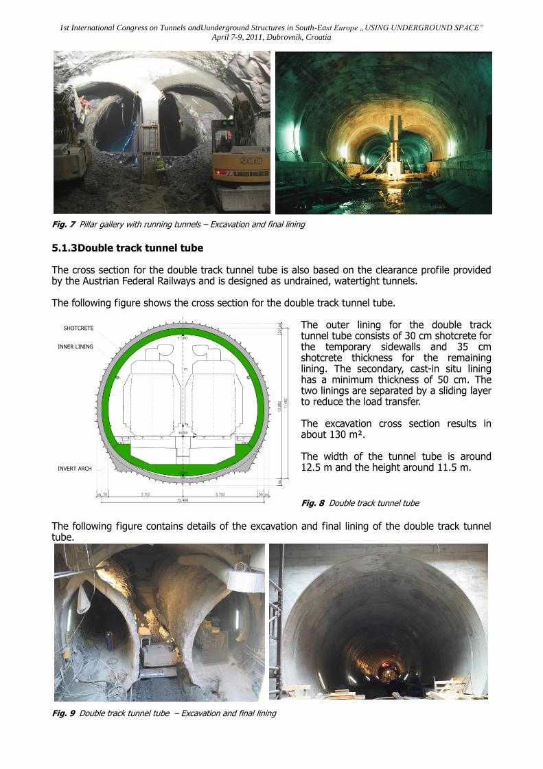
Fig. 7 Pillar gallery with running tunnels – Excavation and final lining
5.1.3 Double track tunnel tube The cross section for the double track tunnel tube is also based on the clearance profile provided by the Austrian Federal Railways and is designed as undrained, watertight tunnels. The following figure shows the cross section for the double track tunnel tube.
The outer lining for the double track tunnel tube consists of 30 cm shotcrete for the temporary sidewalls and 35 cm shotcrete thickness for the remaining lining. The secondary, cast-in situ lining has a minimum thickness of 50 cm. The two linings are separated by a sliding layer to reduce the load transfer. The excavation cross section results in about 130 m². The width of the tunnel tube is around 12.5 m and the height around 11.5 m.
Fig. 8 Double track tunnel tube
The following figure contains details of the excavation and final lining of the double track tunnel tube.
Fig. 9 Double track tunnel tube – Excavation and final lining
1st International Congress on Tunnels andUunderground Structures in South-East Europe „USING UNDERGROUND SPACE“
April 7-9, 2011, Dubrovnik, Croatia
SHOTCRETE
INNER LINING
INVERT ARCH
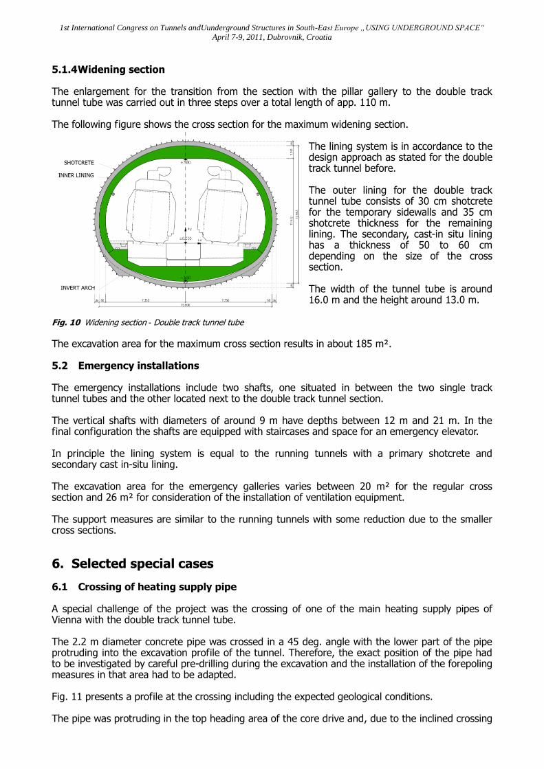
5.1.4 Widening section The enlargement for the transition from the section with the pillar gallery to the double track tunnel tube was carried out in three steps over a total length of app. 110 m. The following figure shows the cross section for the maximum widening section.
The lining system is in accordance to the design approach as stated for the double track tunnel before. The outer lining for the double track tunnel tube consists of 30 cm shotcrete for the temporary sidewalls and 35 cm shotcrete thickness for the remaining lining. The secondary, cast-in situ lining has a thickness of 50 to 60 cm depending on the size of the cross section. The width of the tunnel tube is around 16.0 m and the height around 13.0 m.
Fig. 10 Widening section - Double track tunnel tube The excavation area for the maximum cross section results in about 185 m². 5.2 Emergency installations The emergency installations include two shafts, one situated in between the two single track tunnel tubes and the other located next to the double track tunnel section. The vertical shafts with diameters of around 9 m have depths between 12 m and 21 m. In the final configuration the shafts are equipped with staircases and space for an emergency elevator. In principle the lining system is equal to the running tunnels with a primary shotcrete and secondary cast in-situ lining. The excavation area for the emergency galleries varies between 20 m² for the regular cross section and 26 m² for consideration of the installation of ventilation equipment. The support measures are similar to the running tunnels with some reduction due to the smaller cross sections.
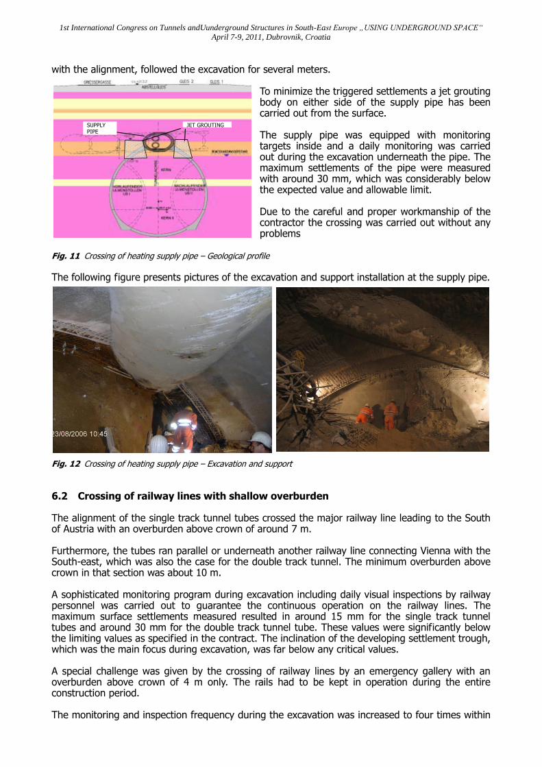
6. Selected special cases 6.1 Crossing of heating supply pipe A special challenge of the project was the crossing of one of the main heating supply pipes of Vienna with the double track tunnel tube. The 2.2 m diameter concrete pipe was crossed in a 45 deg. angle with the lower part of the pipe protruding into the excavation profile of the tunnel. Therefore, the exact position of the pipe had to be investigated by careful pre-drilling during the excavation and the installation of the forepoling measures in that area had to be adapted. Fig. 11 presents a profile at the crossing including the expected geological conditions. The pipe was protruding in the top heading area of the core drive and, due to the inclined crossing
1st International Congress on Tunnels andUunderground Structures in South-East Europe „USING UNDERGROUND SPACE“
April 7-9, 2011, Dubrovnik, Croatia
JET GROUTING SUPPLY PIPE
with the alignment, followed the excavation for several meters. To minimize the triggered settlements a jet grouting body on either side of the supply pipe has been carried out from the surface. The supply pipe was equipped with monitoring targets inside and a daily monitoring was carried out during the excavation underneath the pipe. The maximum settlements of the pipe were measured with around 30 mm, which was considerably below the expected value and allowable limit. Due to the careful and proper workmanship of the contractor the crossing was carried out without any problems
Fig. 11 Crossing of heating supply pipe – Geological profile
The following figure presents pictures of the excavation and support installation at the supply pipe.
Fig. 12 Crossing of heating supply pipe – Excavation and support
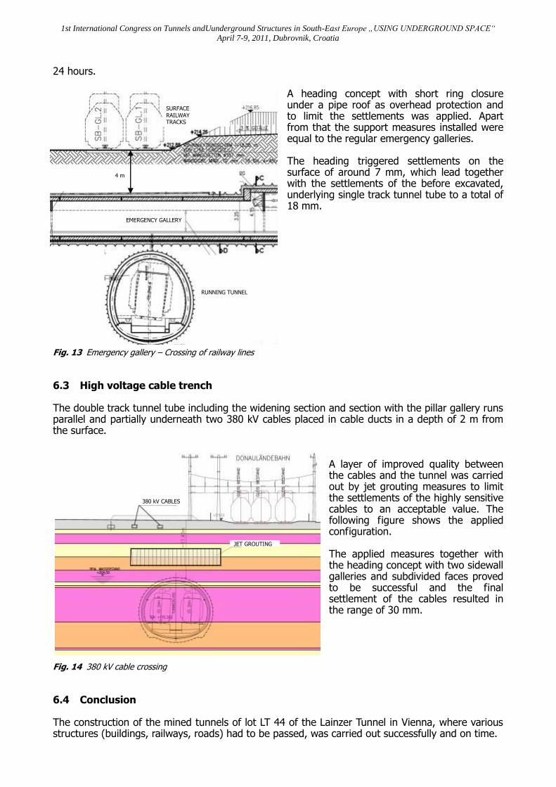
6.2 Crossing of railway lines with shallow overburden The alignment of the single track tunnel tubes crossed the major railway line leading to the South of Austria with an overburden above crown of around 7 m. Furthermore, the tubes ran parallel or underneath another railway line connecting Vienna with the South-east, which was also the case for the double track tunnel. The minimum overburden above crown in that section was about 10 m. A sophisticated monitoring program during excavation including daily visual inspections by railway personnel was carried out to guarantee the continuous operation on the railway lines. The maximum surface settlements measured resulted in around 15 mm for the single track tunnel tubes and around 30 mm for the double track tunnel tube. These values were significantly below the limiting values as specified in the contract. The inclination of the developing settlement trough, which was the main focus during excavation, was far below any critical values. A special challenge was given by the crossing of railway lines by an emergency gallery with an overburden above crown of 4 m only. The rails had to be kept in operation during the entire construction period. The monitoring and inspection frequency during the excavation was increased to four times within
1st International Congress on Tunnels andUunderground Structures in South-East Europe „USING UNDERGROUND SPACE“
April 7-9, 2011, Dubrovnik, Croatia
EMERGENCY GALLERY
4 m
SURFACE
RAILWAY TRACKS
RUNNING TUNNEL
380 kV CABLES
JET GROUTING
24 hours. A heading concept with short ring closure under a pipe roof as overhead protection and to limit the settlements was applied. Apart from that the support measures installed were equal to the regular emergency galleries. The heading triggered settlements on the surface of around 7 mm, which lead together with the settlements of the before excavated, underlying single track tunnel tube to a total of 18 mm.
Fig. 13 Emergency gallery – Crossing of railway lines
6.3 High voltage cable trench The double track tunnel tube including the widening section and section with the pillar gallery runs parallel and partially underneath two 380 kV cables placed in cable ducts in a depth of 2 m from the surface.
A layer of improved quality between the cables and the tunnel was carried out by jet grouting measures to limit the settlements of the highly sensitive cables to an acceptable value. The following figure shows the applied configuration. The applied measures together with the heading concept with two sidewall galleries and subdivided faces proved to be successful and the final settlement of the cables resulted in the range of 30 mm.
Fig. 14 380 kV cable crossing
6.4 Conclusion The construction of the mined tunnels of lot LT 44 of the Lainzer Tunnel in Vienna, where various structures (buildings, railways, roads) had to be passed, was carried out successfully and on time.

1st International Congress on Tunnels andUunderground Structures in South-East Europe „USING UNDERGROUND SPACE“
April 7-9, 2011, Dubrovnik, Croatia
The triggered settlements were all below the set limits and no negative impact on the surroundings was given. A sophisticated and proper workmanship of the contractor together with a tight monitoring and control system of the deformations and settlements was the key to success. A quick response to deviating conditions in the filed during excavation together with an adaptation of the excavation sequence and support installation helped to optimize the construction and to control the construction impact. For such an approach a close collaboration between the client, the designer, the representatives of the client on site and the contractor was inevitable and guaranteed to avoid critical situations or overcome difficult conditions during the execution of the works. After finalization Tunnel Lainz will help to improve the rail traffic situation in Vienna and the living conditions in the neighbourhoods along the existing rail connection on the surface. 6.5 References [1] ÖBB – Infrastruktur Bau AG (2005); „Lainzer Tunnel, Verbindungsstrecke zwischen West-, Süd- und
Donauländebahn; Teilabschnitt Anbindung Donauländebahn, Baulos LT 44 Güterschleife“; - Tender Documents
[2] PGLT Planungsgemeinschaft Lainzer Tunnel (2005); „Lainzer Tunnel Baulos LT 44 – Güterschleife“, Construction
Design
[3] PGLT Planungsgemeinschaft Lainzer Tunnel (2008); “ Lainzer Tunnel Baulos LT44 – Güterschleife“,
Geotechnischer Schlussbericht (Geotechnical Monitoring Report)