Tuneable hydrophoretic separation using elastic deformation of … · 2009-08-15 · microfluidic...
4
Tuneable hydrophoretic separation using elastic deformation of poly(dimethylsiloxane)† Sungyoung Choi and Je-Kyun Park * Received 13th November 2008, Accepted 2nd March 2009 First published as an Advance Article on the web 13th March 2009 DOI: 10.1039/b820364d This paper demonstrates a method for tuning elastomeric microchannels for hydrophoretic separation made in poly(dimethylsiloxane) (PDMS). Uniform compressive strain is imposed on the elastomeric microchannel between two acrylic substrates by fastening the bolts. The elastomeric microchannel can change its cross-section during compression, simultaneously tuning the criterion for hydrophoretic ordering. The change of the channel cross-section under compression is studied using a confocal microscope and finite element method (FEM). By pressing the channel for hydrophoretic separation, we achieved tuning of the separation criterion from 7 to 2.5 mm in particle diameter. Microfabrication allows for engineering fluidic devices with accurate and well-defined channel dimensions at micro- or nano- scale. In microfabricated devices, a detailed understanding of fluid transport has been contributed to the development of new techniques for sorting bioparticles. Microfluidic networks, a connected set of microchannels, have been used to separate blood plasma and isolate leukocytes by precisely controlling the ratio of the hydrodynamic resistances between the micro- channels. 1–3 Microfabricated filters with precise pore sizes were designed for leukocyte enrichment, leukapheresis, and macro- molecular separation. 4–6 Particle separation in a pinched micro- channel has been implemented by pushing and aligning particles to the channel wall. 7 Regular sieve structures with homogeneous nano-pores have been used to continuously separate DNA and proteins improving our understanding of their separation processes. 8–10 Such devices have great potential in cellular and molecular separation applications, yet they lack the flexibility for particle separation. As changing separation targets with ones of new size, it is inevitable to modify the devices with new designs and dimensions. Soft-lithography represents non-conventional lithographic techniques using elastomeric materials, mostly poly- (dimethylsiloxane) (PDMS). 11,12 The PDMS elastomer is a soft material with Young’s modulus of approximately 750 kPa, allowing the design and fabrication of flexible microfluidic systems that can adjust the dimension and shape of a micro- channel by applying mechanical loads. Adjustable nano- channels made in PDMS were used to selectively transport nanoparticles through dynamic modulation of the channel cross-section. 13 Tuneable separation in a pinched microchannel has been implemented by using microvalves that modulate the ratio of the hydrodynamic resistances between outlet chan- nels. 14 In a micropost array for deterministic lateral displacement, a critical particle size for separation has been tuned by stretching the device. 15 Recently, micron- and submicron-scale obstacles have been used to separate microparticles, cells, and macromolecules by hydrophoresis which is the movement of suspended particles under the influence of the pressure field induced by the obsta- cles. 16–18 This technique takes advantage of a sheathless method, passive operation, and single channel. However, the micro- fabricated obstacles for hydrophoresis also have the aforemen- tioned flexibility problem. To assume hydrophoretic ordering, the diameter of particles should be more than the half of the obstacle gap (Fig. 1). 18 As changing separation targets with ones Fig. 1 Size-tuneable microfluidic device for hydrophoretic separation. The elastomeric channel consists of an anisotropic obstacle array to induce hydrophoretic ordering of particles. A fluid flow is applied along the y-axis. (A) Particles (d in diameter) smaller than h 1 /2 follow the rotational flow without hydrophoretic ordering. (B) By compression of the device (H in thickness) into HDH, the obstacle gap can be adjusted to h 2 < 2d where the particles are in hydrophoretic ordering. Department of Bio and Brain Engineering, College of Life Science and Bioengineering, KAIST, 335 Gwahangno, Yuseong-gu, Daejeon, 305-701, Republic of Korea. E-mail: [email protected]; Fax: +82-42-350-4310; Tel: +82-42-350-4315 † Electronic supplementary information (ESI) available: Figs. S1 and S2. See DOI: 10.1039/b820364d 1962 | Lab Chip, 2009, 9, 1962–1965 This journal is ª The Royal Society of Chemistry 2009 TECHNICAL NOTE www.rsc.org/loc | Lab on a Chip
Transcript of Tuneable hydrophoretic separation using elastic deformation of … · 2009-08-15 · microfluidic...
TECHNICAL NOTE www.rsc.org/loc | Lab on a Chip
Tuneable hydrophoretic separation using elastic deformation ofpoly(dimethylsiloxane)†
Sungyoung Choi and Je-Kyun Park*
Received 13th November 2008, Accepted 2nd March 2009
First published as an Advance Article on the web 13th March 2009
DOI: 10.1039/b820364d
This paper demonstrates a method for tuning elastomeric microchannels for hydrophoretic separation
made in poly(dimethylsiloxane) (PDMS). Uniform compressive strain is imposed on the elastomeric
microchannel between two acrylic substrates by fastening the bolts. The elastomeric microchannel can
change its cross-section during compression, simultaneously tuning the criterion for hydrophoretic
ordering. The change of the channel cross-section under compression is studied using a confocal
microscope and finite element method (FEM). By pressing the channel for hydrophoretic separation,
we achieved tuning of the separation criterion from 7 to 2.5 mm in particle diameter.
Microfabrication allows for engineering fluidic devices with
accurate and well-defined channel dimensions at micro- or nano-
scale. In microfabricated devices, a detailed understanding of
fluid transport has been contributed to the development of new
techniques for sorting bioparticles. Microfluidic networks,
a connected set of microchannels, have been used to separate
blood plasma and isolate leukocytes by precisely controlling the
ratio of the hydrodynamic resistances between the micro-
channels.1–3 Microfabricated filters with precise pore sizes were
designed for leukocyte enrichment, leukapheresis, and macro-
molecular separation.4–6 Particle separation in a pinched micro-
channel has been implemented by pushing and aligning particles
to the channel wall.7 Regular sieve structures with homogeneous
nano-pores have been used to continuously separate DNA and
proteins improving our understanding of their separation
processes.8–10 Such devices have great potential in cellular and
molecular separation applications, yet they lack the flexibility for
particle separation. As changing separation targets with ones of
new size, it is inevitable to modify the devices with new designs
and dimensions.
Soft-lithography represents non-conventional lithographic
techniques using elastomeric materials, mostly poly-
(dimethylsiloxane) (PDMS).11,12 The PDMS elastomer is a soft
material with Young’s modulus of approximately 750 kPa,
allowing the design and fabrication of flexible microfluidic
systems that can adjust the dimension and shape of a micro-
channel by applying mechanical loads. Adjustable nano-
channels made in PDMS were used to selectively transport
nanoparticles through dynamic modulation of the channel
cross-section.13 Tuneable separation in a pinched microchannel
has been implemented by using microvalves that modulate the
ratio of the hydrodynamic resistances between outlet chan-
nels.14 In a micropost array for deterministic lateral
Department of Bio and Brain Engineering, College of Life Science andBioengineering, KAIST, 335 Gwahangno, Yuseong-gu, Daejeon, 305-701,Republic of Korea. E-mail: [email protected]; Fax: +82-42-350-4310;Tel: +82-42-350-4315
† Electronic supplementary information (ESI) available: Figs. S1 and S2.See DOI: 10.1039/b820364d
1962 | Lab Chip, 2009, 9, 1962–1965
displacement, a critical particle size for separation has been
tuned by stretching the device.15
Recently, micron- and submicron-scale obstacles have been
used to separate microparticles, cells, and macromolecules by
hydrophoresis which is the movement of suspended particles
under the influence of the pressure field induced by the obsta-
cles.16–18 This technique takes advantage of a sheathless method,
passive operation, and single channel. However, the micro-
fabricated obstacles for hydrophoresis also have the aforemen-
tioned flexibility problem. To assume hydrophoretic ordering,
the diameter of particles should be more than the half of the
obstacle gap (Fig. 1).18 As changing separation targets with ones
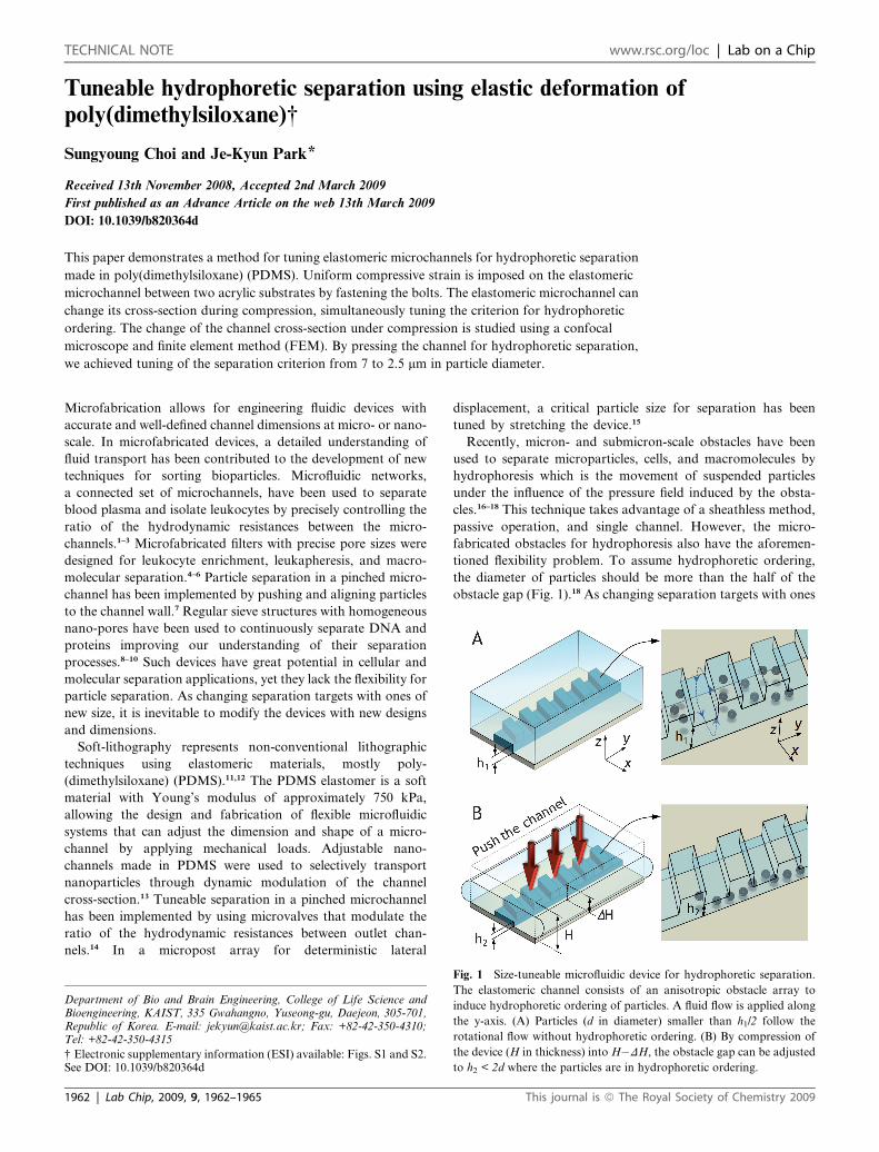
Fig. 1 Size-tuneable microfluidic device for hydrophoretic separation.
The elastomeric channel consists of an anisotropic obstacle array to
induce hydrophoretic ordering of particles. A fluid flow is applied along
the y-axis. (A) Particles (d in diameter) smaller than h1/2 follow the
rotational flow without hydrophoretic ordering. (B) By compression of
the device (H in thickness) into H�DH, the obstacle gap can be adjusted
to h2 < 2d where the particles are in hydrophoretic ordering.
This journal is ª The Royal Society of Chemistry 2009

Fig. 2 Confocal cross-section images of the microchannel for hydro-
phoretic separation. (A) Schematic of the channel geometry filled with
fluorescein isothiocyanate (FITC). (B) Cross-section a0a (upper) and b0b
(lower) without compression. (C) Cross-section a0a (upper) and b0b
(lower) under compression. Applied compressive strain makes the cross-
sectional area decrease and lowers the channel height (lateral and vertical
scale bars¼ 10 mm). The blurring at the bottom boundaries of the images
in panel C might be due to the scattering at the surface of the acrylic
substrate. The dashed lines are drawn to clarify the top and bottom
boundaries of the channel.
of new size, the devices have to be newly designed and fabricated
with appropriate dimensions. To overcome this limitation we
demonstrate a tuneable elastomeric microchannel with aniso-
tropic obstacles whose gap can be adjustable by applying
compressive forces. We present a compression system and
compression conditions for tuning channel dimension and
geometry to separate target particles of many different sizes.
Experimental
We fabricated hydrophoretic devices incorporating anisotropic
microfluidic obstacles in PDMS using two-step photolithog-
raphy, similarly described in our previous work.18 The channels
are 50 mm wide and 40 mm height with 180 obstacles with an
obstacle gap of 13 mm, a thickness of 23 mm, and a pitch distance
of 27 mm. The obstacles are inclined at an angle of 80 to the right
side wall. The deviations of all dimensions were below 5.5%.
Fluorescent polystyrene beads with 1 (green), 4 (red), and 10
mm (green) diameters were purchased from Polysciences (War-
rington, PA) and Molecular Probes (Eugene, OR). The beads
were prepared in 2% pluronic F68 solution (Sigma-Aldrich, St.
Louis, MO) with an average concentration of �2.0 � 103, 7.3 �102, and 1.8 � 102 mL�1, respectively.
A two-photon laser scanning microscope (LSM510; Carl Zeiss,
Germany) with femto-second pulsed laser (Chameleon, Coherent,
Santa Clara, CA) was used to provide cross-section images of the
deformed channels. We measured the thickness of the PDMS
devices and its variation under compression using vernier calipers.
Finite-element calculations were performed to study the rela-
tionship between the uniform compressive displacement applied
to PDMS devices and channel deformation using a commercial
software (CFD-ACE+; ESI, Huntsville, AL). The 2D mesh for
finite-element calculations of PDMS channel compression has
thickness of 3.68 mm and width of 6 mm (see ESI Fig. S1†). The
microchannel of 13 mm in height and 50 mm width is defined at
the bottom of the 2D mesh. The Poisson ratio of PDMS is close
to 0.49, which can be treated as a perfectly incompressible
material.19 The Young’s modulus of PDMS is assumed to be 750
kPa.19 The right and left walls of the device are set as the free
boundary condition. The bottom wall is set as the fixed boundary
condition. Setting the constant displacement values for the top
wall as the prescribed displacement boundary condition, we
applied compressive forces to the mesh.
Results and discussion
Principle of tuneable hydrophoretic separation
A compression system is composed of bolts, nuts, and acrylic
substrates (see ESI Fig. S2†). Uniform compressive strain is
imposed on the elastomeric microchannel between two acrylic
substrates by fastening the bolts. The magnitude of compressive
strain applied to the microchannel is varied by changing
compressive displacement. Hydrophoretic ordering is deter-
mined by a kind of steric hindrance mechanism (Fig. 1).18 Steric
hindrance occurs when the rotational motion of particles is
affected by the existence of the obstacles. The particle–obstacle
interaction deflects large particles assuming hydrophoretic
ordering from their streamline and leads to equivalent flow
paths. In contrast, relatively smaller particles out of the critical
This journal is ª The Royal Society of Chemistry 2009
ordering condition just follow the rotational flows induced by the
anisotropic resistance of the obstacles. To assume hydrophoretic
ordering, the diameter of particles should be more than the half
of the obstacle gap. Conversely speaking, the diameter range for
hydrophoretic ordering can be modulated by adjusting the height
of the obstacle gap.18 For example, in the non-deformed PDMS
device, the rotational motion of particles (d in diameter) smaller
than the half of the obstacle gap (h1) cannot be affected by the
existence of the obstacles and follows the rotational streams
(Fig. 1A). The channel deformation by the compressive
displacement hinders the particles (d > h2/2) from following the
rotational flows and allows hydrophoretic ordering (Fig. 1B).
Application of compressive displacement to PDMS devices
In order to acquire cross-section images of the microchannel under
compressive strain, we filled the microchannel with fluorescein
isothiocyanate dye as contrast (Fig. 2A). The frames in Fig. 2B
are confocal micrographs of the cross-sections. When a uni-
form compressive strain (DH/H ¼ 0.16) is applied to the entire
PDMS device (H ¼ 3.68 mm), the top wall of the microchannel
deflects downward (Fig. 2C). The microfabricated channel with
a rectangular cross-section has a maximum deflection at the
middle.20 After compression, the gap height at the middle (cross-
section a0–a in Fig. 2A) was changed from 13 mm to 4.9 mm.
Lab Chip, 2009, 9, 1962–1965 | 1963

The large compressive strain of 0.16 (DH¼ 0.6 mm) applied to the
entire device results in a small channel deflection of 8.1 mm.
Since it is difficult to get analytical results for this structural
mechanics problem, we performed simulations using finite
element method (FEM) and a scaling approximation of the
relationship between the uniform compressive displacement of
the PDMS device and channel deformation. A uniform
compressive displacement is applied over the top wall of the two-
dimensional geometry for FEM simulations (see ESI Fig. S1†).
Rectangular-shaped channels are not changed uniformly under
the uniform compressive displacement (Fig. 3A). The sidewall
deformation of the channels is negligible compared to the extent
of the top wall deformation. In flow channels with a rounded
cross section, the compressive load can be transferred to the
channel edges and cause the uniform deformation of the chan-
nels.21 The FEM results show a linear relationship between the
compressive displacement of the PDMS device and channel
height at the middle, satisfying Hooke’s law (Fig. 3). A relation
describing the maximum variation of a microchannel under
uniform stress follows from Gervais et al.20
Dhmax ¼ cws
E(1)
where Dhmax is the height decrease at mid-width of the channel
under deformation, w is the channel width, s is an applied stress,
E is the Young’s modulus of PDMS, and c is a fit parameter.
Fig. 3 (A) Finite element method (FEM) solutions for compression of
the elastomeric device under prescribed displacements of 0.3, 0.575, and
0.75 mm along the z-axis. A 2D finite-element model as a PDMS device
has thickness (H) of 3.68 mm and width of 6 mm. The microchannel of 13
mm in height and 50 mm in width is defined at the bottom of the 2D mesh.
(B) Maximum channel height vs. compression displacement of PDMS
devices with thickness of 3.68 and 4.68 mm, respectively (:, -: FEM
results). The dashed lines are fitted from eqn. (2) with fit parameters (c) of
1.13 (H ¼ 3.68 mm) and 0.69 (H ¼ 4.68 mm).
1964 | Lab Chip, 2009, 9, 1962–1965
Since the stress–modulus ratio means strain, eqn. (1) can be
rewritten as:
Dhmax ¼ cwDH
H(2)
where DH is the thickness decrease of the entire PDMS device
and H is the thickness of the device. In this scaling approxima-
tion, the channel deformation is proportional to the channel
width and the thickness of the PDMS device rather than the
channel height (Fig. 3B). The former two parameters can be
further used to adjust the channel height for tuneable hydro-
phoretic separation.
Tuneable separation of microparticles
We demonstrated tuneable separation of microparticles with
controlled obstacle gap (Fig. 4). Without compressive displace-
ment, the obstacle gap of 13 mm assures hydrophoretic ordering
of particles more than 7 mm in diameter. Therefore, the 10 mm-
sized beads become focused into the channel middle by hydro-
phoretic ordering, while 4 mm beads are evenly distributed and
separated from the 10 mm beads under a flow rate of 1 mL min�1
(Fig. 4A, C). As mentioned, the hydrophoretic particle motion is
governed by the physical (steric) barrier of the anisotropic
microfluidic obstacles. The particle–obstacle interaction deflects
particles assuming hydrophoretic ordering and makes them
diffuse out of the rotational streamlines (Fig. 1B). At that time,
smaller particles within the critical ordering condition can
approach closer to the top wall of the channel and be exposed to
Fig. 4 Hydrophoretic separation. (A) Fluorescence image showing
separation of 10 (green) and 4 (red) mm beads before compression. The 10
mm beads are in hydrophoretic ordering, whereas the 4 mm beads remain
unfocused. (B) Fluorescence image showing separation of 4 (red) and 1
(green) mm beads after compression. By lowering the obstacle gap, the 4
mm beads are focused to the right sidewall. In contrast, the 1 mm beads are
evenly distributed and separated from the 4 mm beads. (C, D) Fluores-
cence intensities for bead streams in (A) and (B), respectively.
This journal is ª The Royal Society of Chemistry 2009

much higher transverse flows. This steric hindrance mechanism
enables hydrophoretic size separation. The 10 mm-sized beads
smaller than the obstacle gap of 13 mm will be positioned far from
the sidewall, near the channel middle. In addition, although
particles are out of the critical ordering condition, they are still
influenced by the particle–obstacle interaction. Accordingly, the
4 mm-sized beads can follow the steric hindrance mechanism even
though their distribution of the channel width is much larger
than that of particles within the critical ordering condition.
When deformed by uniform compressive strain (DH/H) of 0.16,
the obstacle gap at the middle is tuned from 13 to 4.9 mm in the
PDMS device with thickness (H) of 3.68 mm, simultaneously
changing the trajectory of the 4 mm beads. After the channel
compression, the obstacle gap of 4.9 mm assures hydrophoretic
ordering of particles more than 2.5 mm in diameter. Thus the
4 mm beads focused into the right sidewall are separated from the
1 mm beads that are evenly distributed without hydrophoretic
ordering under a flow rate of 0.4 mL min�1 (Fig. 4B, D). As
mentioned, the height of the obstacle gap (h) is an important
design parameter that determines whether particles (d in diam-
eter) assume hydrophoretic self-ordering in a narrow distribution
of the channel width. Experimentally, we have found that the
obstacles of h # 2d hinder the rotational flows of the particles
and leads to hydrophoretic self-ordering.18 Therefore, the 1 mm-
sized beads out of the critical ordering condition are relatively
free from the particle-obstacle interaction and are positioned in
the wide distribution of the channel width without hydrophoretic
ordering. These results show that this system is capable of sorting
target particles of many different sizes without any modification
of channel dimension or design.
Conclusions
We have described a method of tuning elastomeric micro-
channels made in PDMS using a compression system with bolts,
nuts, and acrylic substrates. This method makes it possible to
adjust the height of the obstacle gap for hydrophoretic separa-
tion. The elastomeric microchannel can change its cross-section
during compression, simultaneously tuning the criterion for
hydrophoretic ordering. The channel deformation can be further
modulated by changing the channel width and the device thick-
ness. Under compressive stress, the microchannels with the same
height but different widths can be deformed into many different
heights by the linear relationship between the channel deforma-
tion and channel width. The partial channel pressing can also
change the microchannels into many different heights that enable
This journal is ª The Royal Society of Chemistry 2009
sequential separation in a hydrophoretic device. By these parallel
operations, the elastomeric microchannel for hydrophoretic
separation can extend its sorting range. We also performed FEM
simulations and a scaling approximation of the relationship
between the uniform compressive displacement of the PDMS
device and channel deformation for various compressive strain
values. These results will be helpful for tuning a hydrophoretic
device or probing different strain applications.
Acknowledgements
This research was supported by the the Korea Science and
Engineering Foundation (KOSEF) NRL Program (R0A-2008-
000-20109-0) and by the Nano/Bio Science and Technology
Program (2005-01291) funded by the Korea government
(MEST). The authors thank the Chung Moon Soul Center for
BioInformation and BioElectronics, KAIST.
References
1 S. Yang, A. €Undar and J. D. Zahn, Lab Chip, 2006, 6, 871.2 S. S. Shevkoplyas, T. Yoshida, L. L. Munn and M. W. Bitensky, Anal.
Chem., 2005, 77, 933.3 M. Yamada and M. Seki, Lab Chip, 2005, 5, 1233.4 V. VanDelinder and A. Groisman, Anal. Chem., 2007, 79, 2023.5 P. Sethu, A. Sin and M. Toner, Lab Chip, 2006, 6, 83.6 C. C. Striemer, T. R. Gaborski, J. L. McGrath and P. M. Fauchet,
Nature, 2007, 445, 749.7 M. Yamada, M. Nakashima and M. Seki, Anal. Chem., 2004, 76,
5465.8 J. Han and H. G. Craighead, Science, 2000, 288, 1026.9 J. Han and H. G. Craighead, Anal. Chem., 2002, 74, 394.
10 J. Fu, R. B. Schoch, A. L. Stevens, S. R. Tannenbaum and J. Han,Nat. Nanotechnol., 2007, 2, 121.
11 Y. Xia and G. M. Whitesides, Annu. Rev. Mater. Sci., 1998, 28, 153.12 D. C. Duffy, J. C. McDonald, O. J. A. Schueller and
G. M. Whitesides, Anal. Chem., 1998, 70, 4974.13 D. Huh, K. L. Mills, X. Zhu, M. A. Burns, M. D. Thouless and
S. Takayama, Nat. Mater., 2007, 6, 424.14 Y. Sai, M. Yamada, M. Yasuda and M. Seki, J. Chromatogr., A, 2006,
1127, 214.15 J. P. Beech and J. O. Tegenfeldt, Lab Chip, 2008, 8, 657.16 S. Choi and J.-K. Park, Lab Chip, 2007, 7, 890.17 S. Choi, S. Song, C. Choi and J.-K. Park, Lab Chip, 2007, 7, 1532.18 S. Choi, S. Song, C. Choi and J.-K. Park, Anal. Chem., 2009, 81, 50.19 D. Armani, C. Liu and N. Aluru, Proc. IEEE Micro Electro
Mechanical Systems, Orlando, FL, USA, 1999, 222–227.20 T. Gervais, J. El-Ali, A. G€unther and K. F. Jensen, Lab Chip, 2006, 6,
500.21 M. A. Unger, H.-P. Chou, T. Thorsen, A. Scherer and S. R. Quake,
Science, 2000, 288, 113.
Lab Chip, 2009, 9, 1962–1965 | 1965