TUNALIData Communication1 Chapter 5 Signal Encoding Techniques.
77
TUNALI Data Communication 1 Chapter 5 Signal Encoding Techniques
-
Upload
moris-perry -
Category
Documents
-
view
229 -
download
0
Transcript of TUNALIData Communication1 Chapter 5 Signal Encoding Techniques.
TUNALI Data Communication 1
Chapter 5
Signal Encoding Techniques
TUNALI Data Communication 2
Encoding and Modulation• Two techniques for data transmission
—Encoding• A data source is encoded into a digital signal• Encoding technique is chosen to optimize
transmission medium
—Modulation• The process of encoding source data onto a carrier
signal with frequency fc
• All modulation techniques involve operation on three signal parameters
– Amplitude– Frequency– Phase
TUNALI Data Communication 3
Encoding Techniques• Digital data, digital signal
• Less complex• Less expensive than digital to analog modulation
• Analog data, digital signal• Sometimes, it is more advantageous to shift to digital domain
• Digital data, analog signal• Some transmission media (unguided media, optical fiber) only
propagate analog signals
• Analog data, analog signal• Analog data transmitted as analog signal easily and cheaply:
voice transmission over voice grade lines• Shift the bw of baseband signal to another portion of the
spectrum– Multiple signals can share the transmission medium– Frequency Division Multiplexing
TUNALI Data Communication 4
Digital Data, Digital Signal• Digital signal
—Discrete, discontinuous voltage pulses—Each pulse is a signal element—Binary data encoded into signal elements—In the simplest case, one-to-one
correspondence between data and signal elements
TUNALI Data Communication 5
Terms (1)• Unipolar
—All signal elements have same sign
• Polar—One logic state represented by positive
voltage the other by negative voltage
• Data rate—Rate of data transmission in bits per second
• Duration or length of a bit—Time taken for transmitter to emit the bit
TUNALI Data Communication 6
Terms (2)• Modulation rate
—Rate at which the signal level changes—Measured in baud = signal elements per
second
• Mark and Space—Binary 1 and Binary 0 respectively
TUNALI Data Communication 7
Interpreting Signals• Need to know
—Timing of bits - when they start and end—Signal levels
• Factors affecting successful interpreting of signals—Signal to noise ratio—Data rate—Bandwidth
TUNALI Data Communication 8
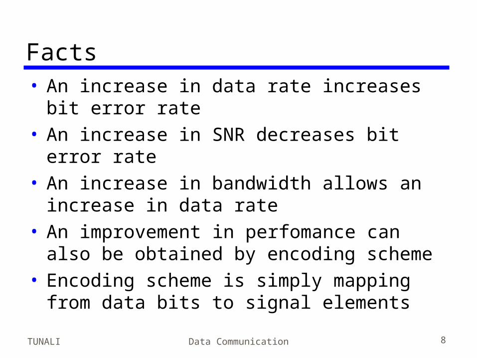
Facts• An increase in data rate increases bit error
rate• An increase in SNR decreases bit error
rate• An increase in bandwidth allows an
increase in data rate• An improvement in perfomance can also
be obtained by encoding scheme• Encoding scheme is simply mapping from
data bits to signal elements
TUNALI Data Communication 9
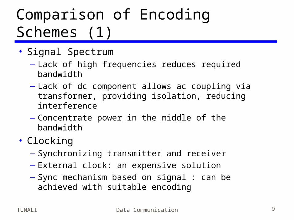
Comparison of Encoding Schemes (1)• Signal Spectrum
—Lack of high frequencies reduces required bandwidth
—Lack of dc component allows ac coupling via transformer, providing isolation, reducing interference
—Concentrate power in the middle of the bandwidth
• Clocking—Synchronizing transmitter and receiver—External clock: an expensive solution—Sync mechanism based on signal : can be achieved
with suitable encoding
TUNALI Data Communication 10
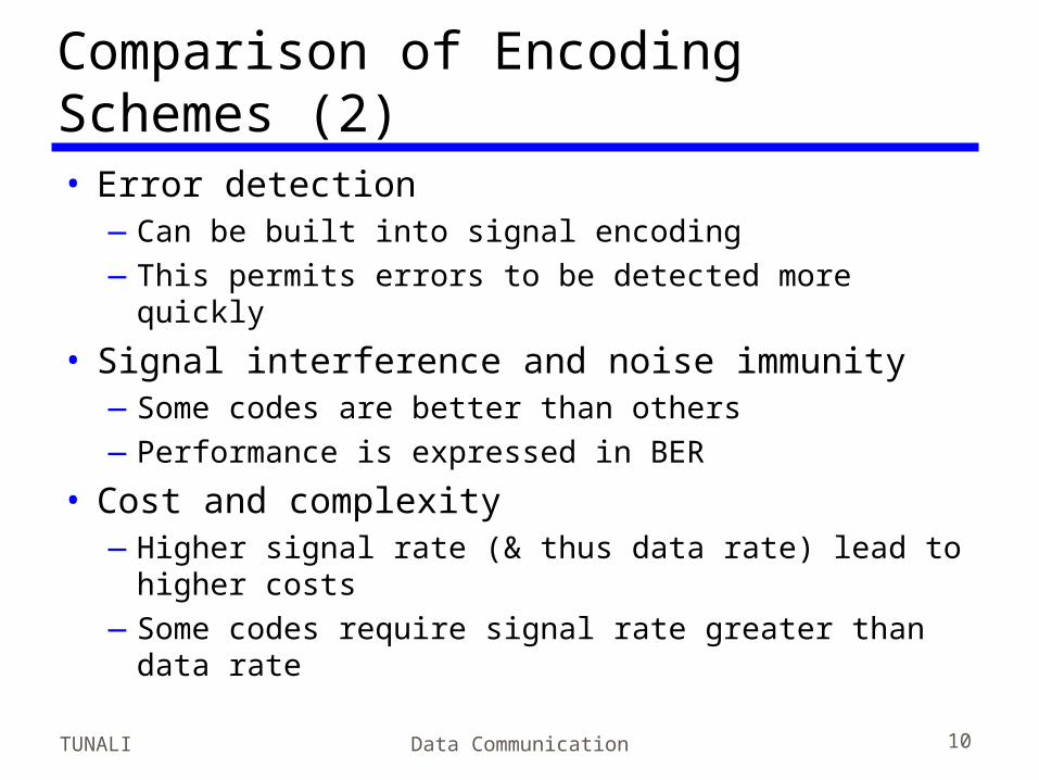
Comparison of Encoding Schemes (2)• Error detection
—Can be built into signal encoding—This permits errors to be detected more quickly
• Signal interference and noise immunity—Some codes are better than others—Performance is expressed in BER
• Cost and complexity—Higher signal rate (& thus data rate) lead to
higher costs—Some codes require signal rate greater than data
rate
TUNALI Data Communication 11
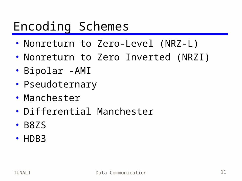
Encoding Schemes• Nonreturn to Zero-Level (NRZ-L)• Nonreturn to Zero Inverted (NRZI)• Bipolar -AMI• Pseudoternary• Manchester• Differential Manchester• B8ZS• HDB3
TUNALI Data Communication 12
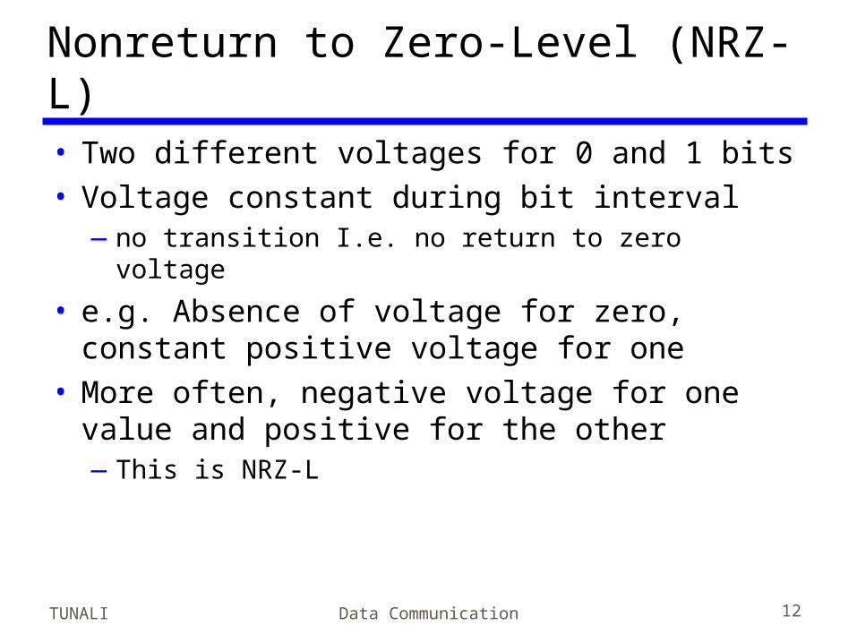
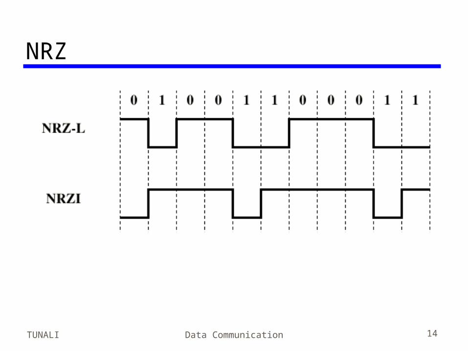
Nonreturn to Zero-Level (NRZ-L)• Two different voltages for 0 and 1 bits• Voltage constant during bit interval
—no transition I.e. no return to zero voltage
• e.g. Absence of voltage for zero, constant positive voltage for one
• More often, negative voltage for one value and positive for the other—This is NRZ-L
TUNALI Data Communication 13
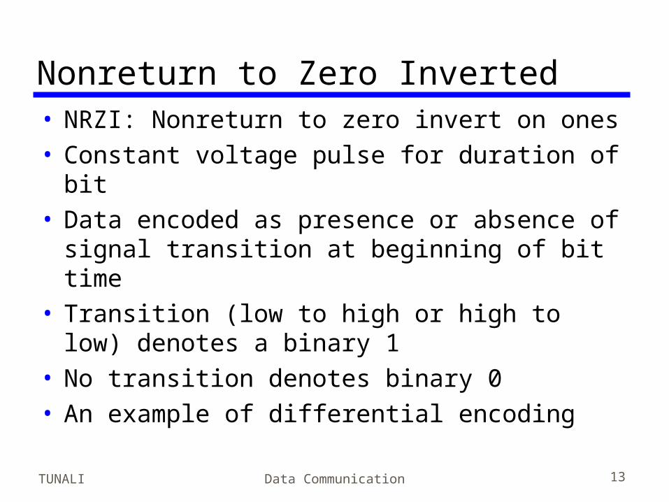
Nonreturn to Zero Inverted• NRZI: Nonreturn to zero invert on ones• Constant voltage pulse for duration of bit• Data encoded as presence or absence of
signal transition at beginning of bit time• Transition (low to high or high to low)
denotes a binary 1• No transition denotes binary 0• An example of differential encoding
TUNALI Data Communication 14
NRZ
TUNALI Data Communication 15
Differential Encoding• Data represented by changes rather than
levels• More reliable detection of transition rather
than level• In complex transmission layouts it is easy
to lose sense of polarity—E.g. if the leads from an attached device to the
twisted pair accidentally inverted, all NRZ-L bits will be inverted
TUNALI Data Communication 16
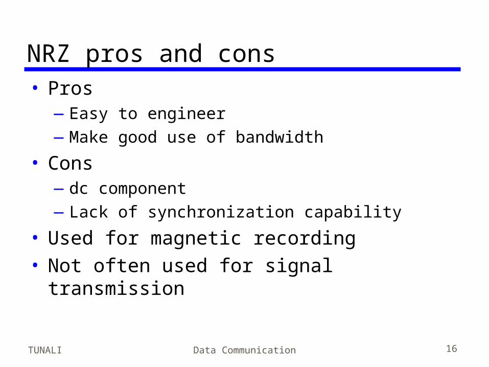
NRZ pros and cons• Pros
—Easy to engineer—Make good use of bandwidth
• Cons—dc component—Lack of synchronization capability
• Used for magnetic recording• Not often used for signal transmission
TUNALI Data Communication 17
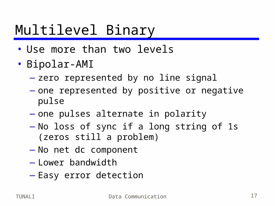
Multilevel Binary• Use more than two levels• Bipolar-AMI
—zero represented by no line signal—one represented by positive or negative pulse—one pulses alternate in polarity—No loss of sync if a long string of 1s (zeros still
a problem)—No net dc component—Lower bandwidth—Easy error detection
TUNALI Data Communication 18
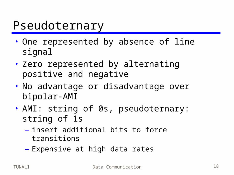
Pseudoternary• One represented by absence of line signal• Zero represented by alternating positive
and negative• No advantage or disadvantage over
bipolar-AMI• AMI: string of 0s, pseudoternary: string of
1s—insert additional bits to force transitions—Expensive at high data rates
TUNALI Data Communication 19
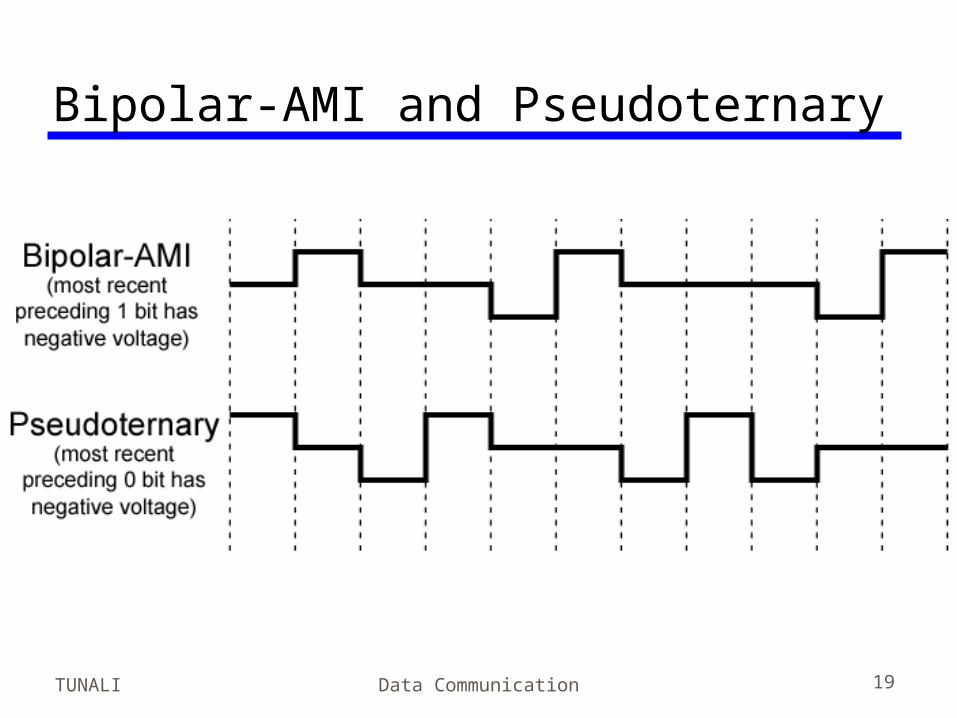
Bipolar-AMI and Pseudoternary
TUNALI Data Communication 20
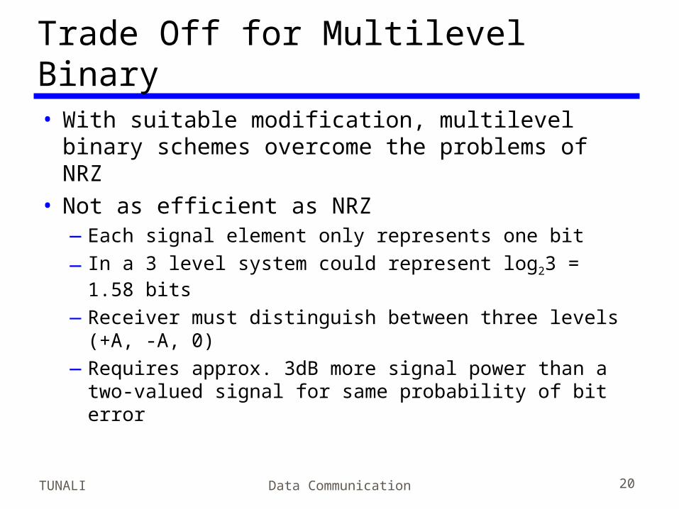
Trade Off for Multilevel Binary• With suitable modification, multilevel binary
schemes overcome the problems of NRZ• Not as efficient as NRZ
—Each signal element only represents one bit
—In a 3 level system could represent log23 = 1.58 bits
—Receiver must distinguish between three levels (+A, -A, 0)
—Requires approx. 3dB more signal power than a two-valued signal for same probability of bit error
TUNALI Data Communication 21
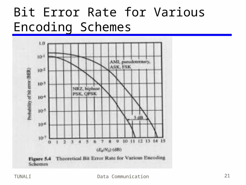
Bit Error Rate for Various Encoding Schemes• Fig 5.4
TUNALI Data Communication 22
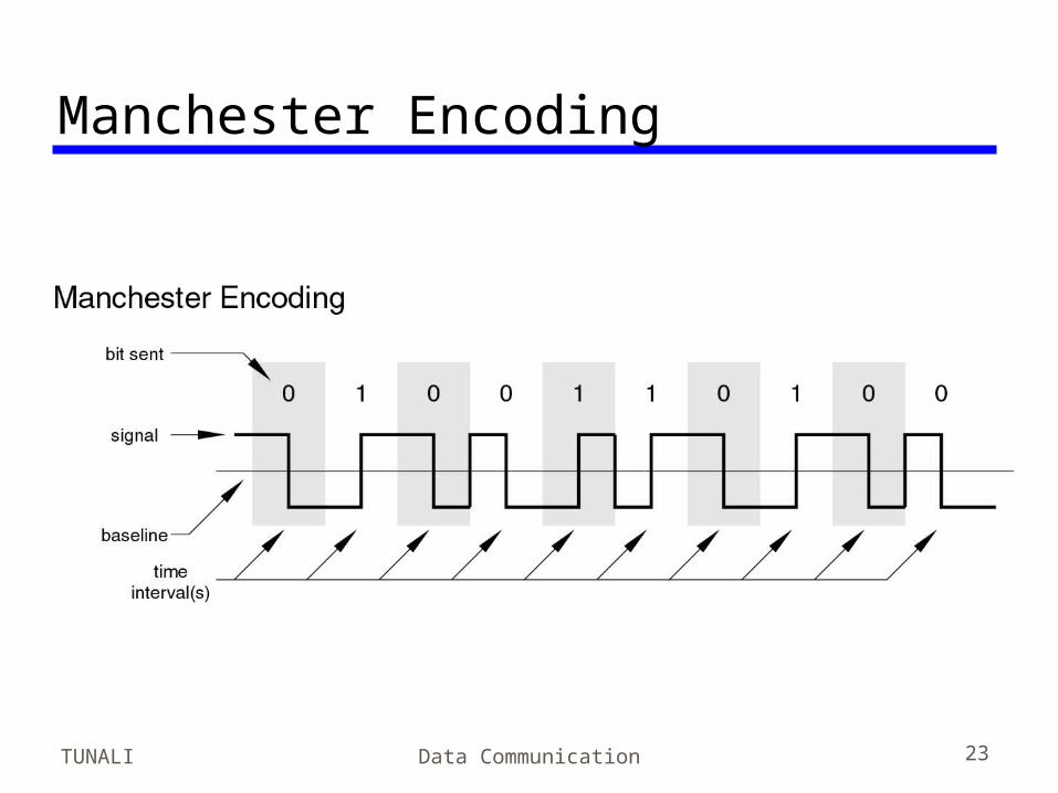
Biphase• Manchester
—Transition in middle of each bit period—Transition serves as clock and data—Low to high represents one—High to low represents zero—Used by IEEE 802.3
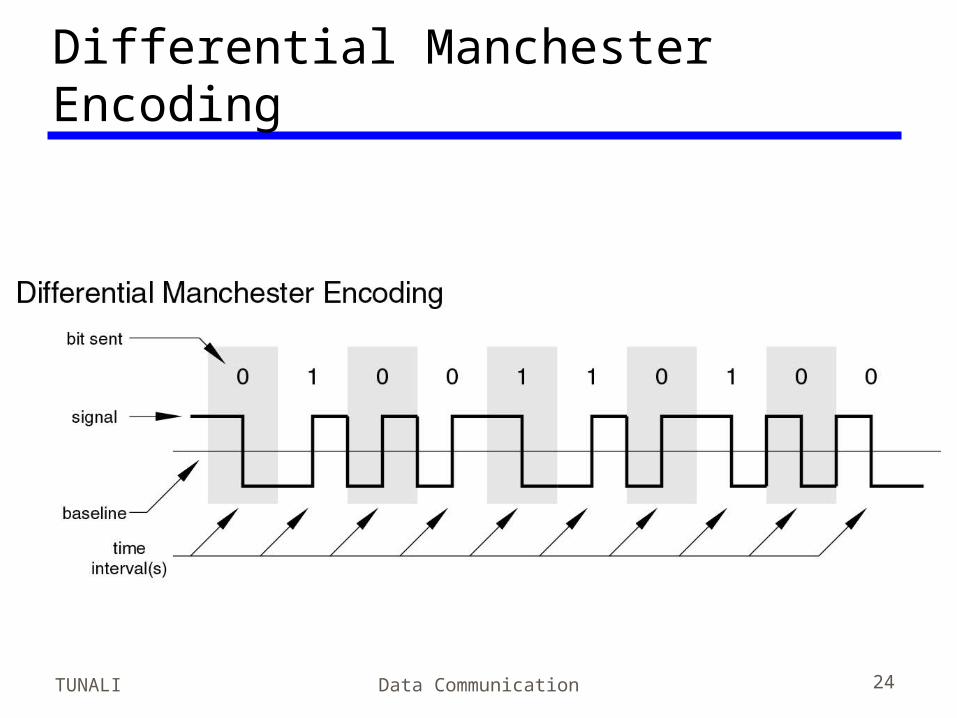
• Differential Manchester—Midbit transition is clocking only—Transition at start of a bit period represents zero—No transition at start of a bit period represents one—Note: this is a differential encoding scheme—Used by IEEE 802.5
TUNALI Data Communication 23
Manchester Encoding
TUNALI Data Communication 24
Differential Manchester Encoding
TUNALI Data Communication 25
Biphase Pros and Cons• Con
—At least one transition per bit time and possibly two
—Maximum modulation rate is twice NRZ—Requires more bandwidth
• Pros—Synchronization on mid bit transition (self
clocking)—No dc component—Error detection
• Absence of expected transition
TUNALI Data Communication 26
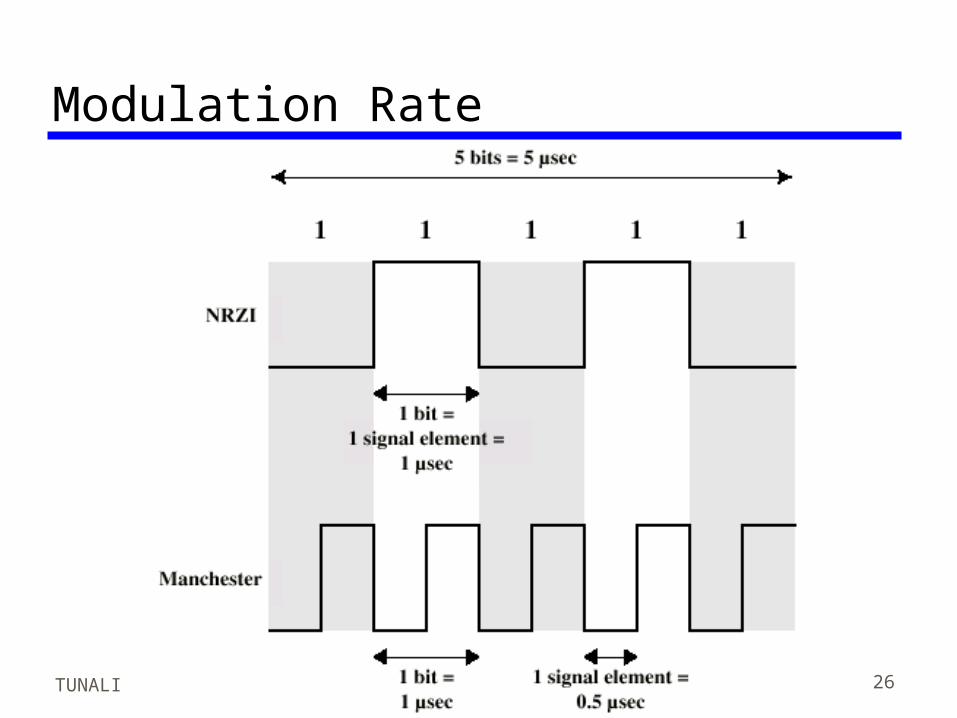
Modulation Rate
TUNALI Data Communication 27
RemarkData rate and modulation rate can differ.
Recall that D=R/b=whereD = modulation rate (baud)R = data rate (bps)b = #bits per signal element
TUNALI Data Communication 28
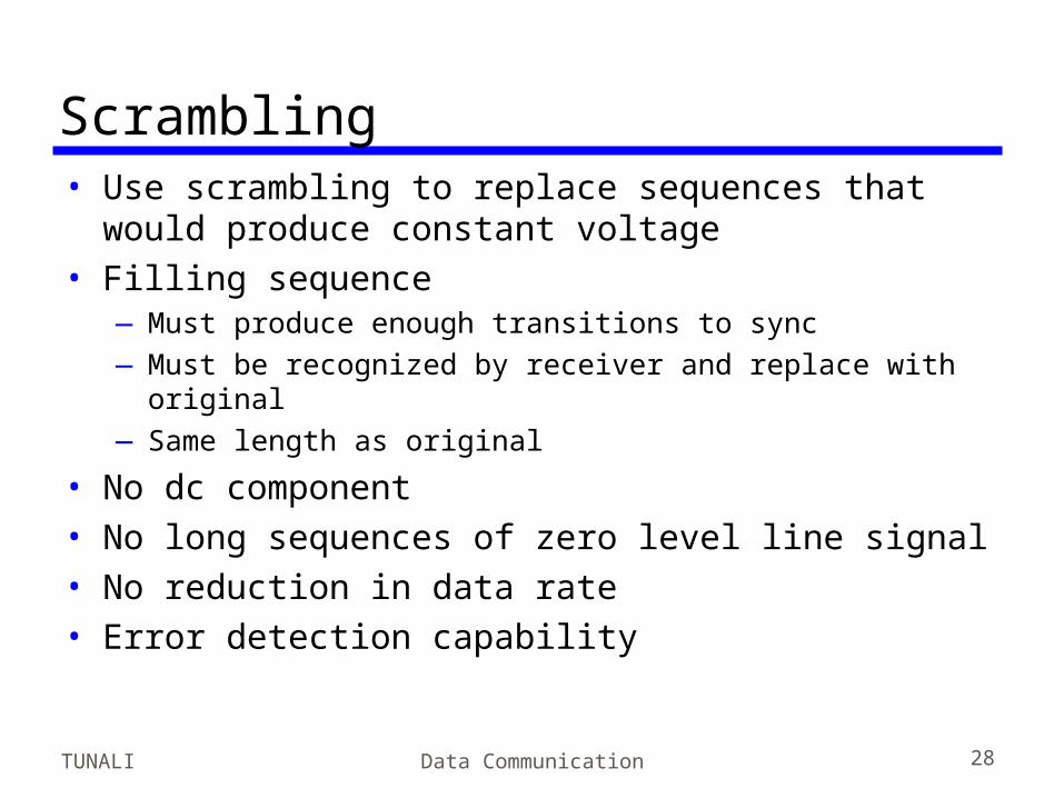
Scrambling• Use scrambling to replace sequences that would
produce constant voltage• Filling sequence
—Must produce enough transitions to sync—Must be recognized by receiver and replace with original—Same length as original
• No dc component• No long sequences of zero level line signal• No reduction in data rate• Error detection capability
TUNALI Data Communication 29
RemarkNote that biphase techniques are mostly
used in LANs. Since high signaling rate is required relative to data rate, these techniques are not suitable for long distance transmission. Scrambling techniques improve this rate by replacing long sequences of zeros by a fixed pattern.
TUNALI Data Communication 30
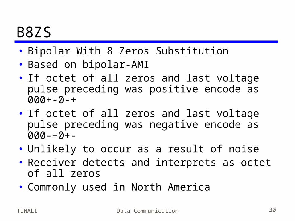
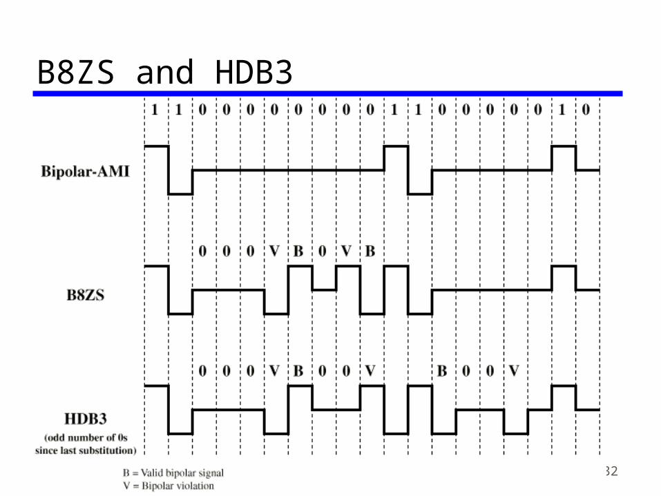
B8ZS• Bipolar With 8 Zeros Substitution• Based on bipolar-AMI• If octet of all zeros and last voltage pulse
preceding was positive encode as 000+-0-+• If octet of all zeros and last voltage pulse
preceding was negative encode as 000-+0+-• Unlikely to occur as a result of noise• Receiver detects and interprets as octet of
all zeros• Commonly used in North America
TUNALI Data Communication 31
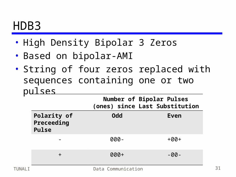
HDB3• High Density Bipolar 3 Zeros• Based on bipolar-AMI• String of four zeros replaced with
sequences containing one or two pulses
Number of Bipolar Pulses (ones) since Last Substitution
Polarity of Preceeding Pulse
Odd Even
- 000- +00+
+ 000+ -00-
TUNALI Data Communication 32
B8ZS and HDB3
TUNALI Data Communication 33
Digital Data, Analog Signal• Public telephone system
—300Hz to 3400Hz – voice frequency range—Use modem (modulator-demodulator)
• Amplitude shift keying (ASK)• Frequency shift keying (FSK)• Phase shift keying (PK)
TUNALI Data Communication 34
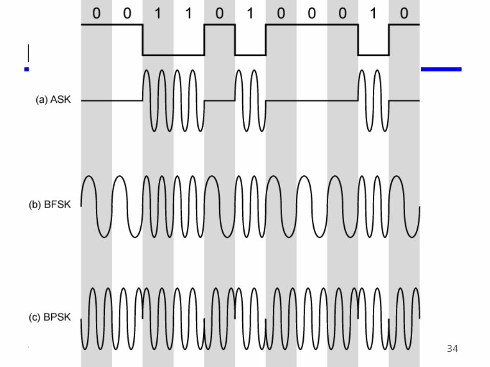
Modulation Techniques
TUNALI Data Communication 35
Amplitude Shift Keying (1)• Two binary values represented by
different amplitudes of carrier frequency• Usually, one amplitude is zero
—i.e. presence and absence of carrier is used
• Susceptible to sudden gain changes• Inefficient• Up to 1200bps on voice grade lines• Used over optical fiber
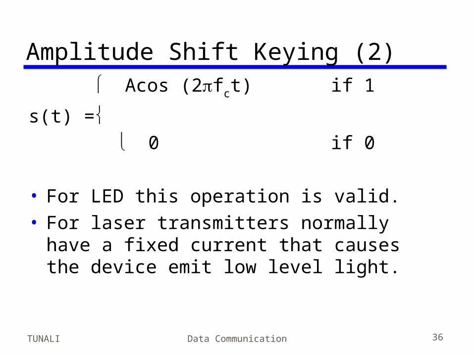
TUNALI Data Communication 36
Amplitude Shift Keying (2) Acos (2fct) if 1
s(t) = 0 if 0 • For LED this operation is valid.• For laser transmitters normally have a
fixed current that causes the device emit low level light.
TUNALI Data Communication 37
Binary Frequency Shift Keying (1)• Most common form is binary FSK (BFSK)• Two binary values represented by two
different frequencies (near carrier)• Less susceptible to error than ASK• Up to 1200bps on voice grade lines• Commonly used for high frequency radio
(3 to 30 MHz)• Used at even higher frequency on LANs
using co-ax
TUNALI Data Communication 38
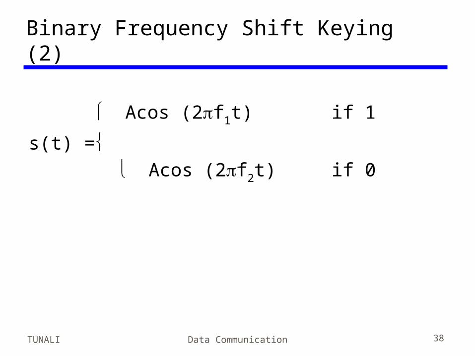
Binary Frequency Shift Keying (2)
Acos (2f1t) if 1
s(t) = Acos (2f2t) if 0
TUNALI Data Communication 39
Multiple FSK• More than two frequencies used• More bandwidth efficient• More prone to error• Each signalling element represents more
than one bit—Each signal element is held for a period of LT
seconds, L: number of bits per signal element, T: bit period
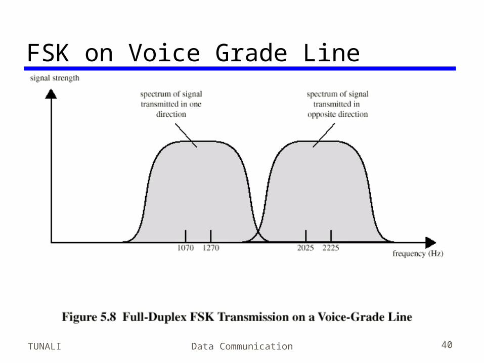
TUNALI Data Communication 40
FSK on Voice Grade Line
TUNALI Data Communication 41
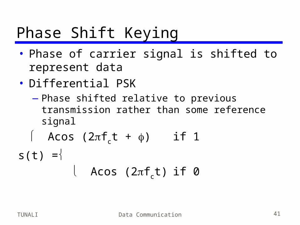
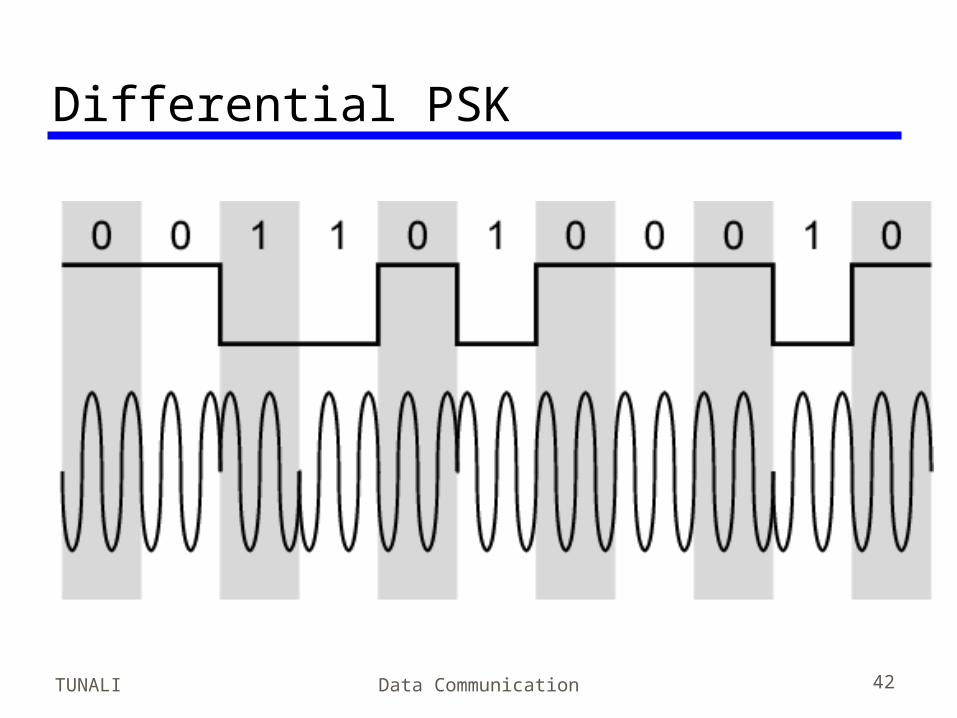
Phase Shift Keying• Phase of carrier signal is shifted to
represent data• Differential PSK
—Phase shifted relative to previous transmission rather than some reference signal
Acos (2fct + ) if 1
s(t) = Acos (2fct) if 0
TUNALI Data Communication 42
Differential PSK
TUNALI Data Communication 43
Quadrature PSK (1)• More efficient use of bw by each signal
element representing more than one bit—e.g. shifts of /2 (90o)—Each element represents two bits—Can use 8 phase angles and have more than
one amplitude—9600bps modem use 12 angles , four of which
have two amplitudes
• Offset QPSK (orthogonal QPSK)—Delay in Q stream
TUNALI Data Communication 44
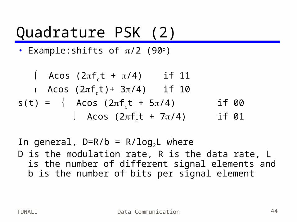
Quadrature PSK (2)• Example:shifts of /2 (90o)
Acos (2fct + /4) if 11
Acos (2fct)+ 3/4) if 10
s(t) = Acos (2fct + 5/4) if 00
Acos (2fct + 7/4) if 01
In general, D=R/b = R/log2L whereD is the modulation rate, R is the data rate, L is the
number of different signal elements and b is the number of bits per signal element
TUNALI Data Communication 45
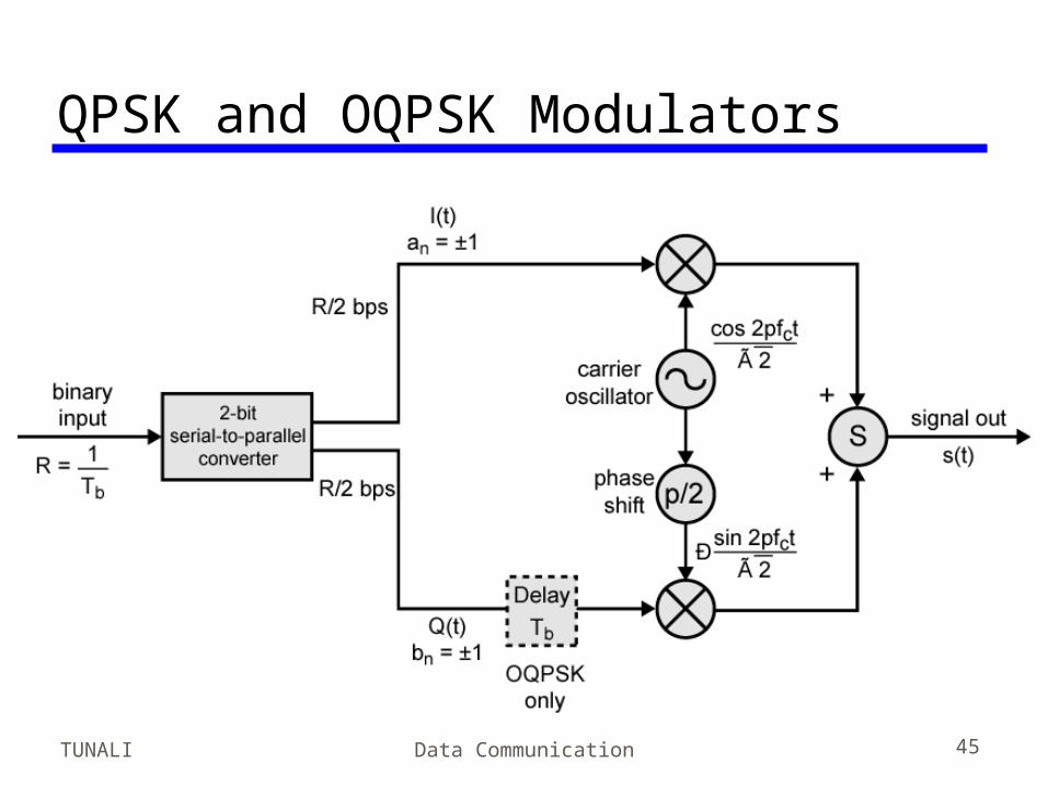
QPSK and OQPSK Modulators
TUNALI Data Communication 46
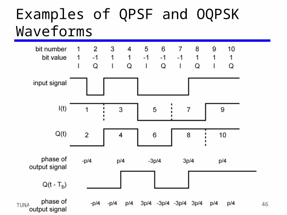
Examples of QPSF and OQPSK Waveforms
TUNALI Data Communication 47
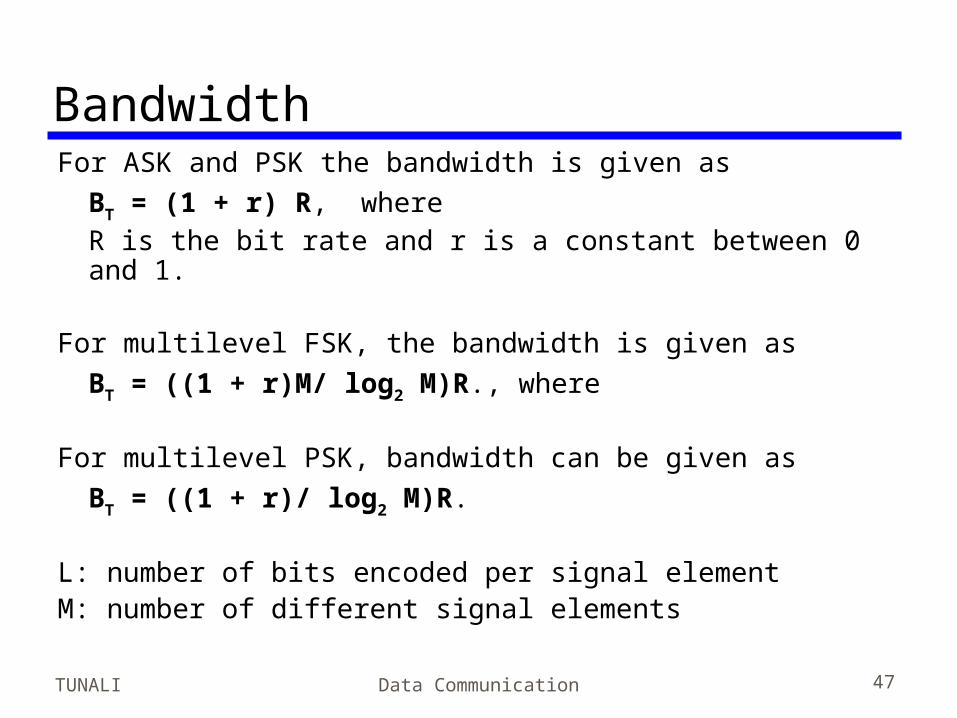
BandwidthFor ASK and PSK the bandwidth is given as
BT = (1 + r) R, where R is the bit rate and r is a constant between 0 and 1.
For multilevel FSK, the bandwidth is given as
BT = ((1 + r)M/ log2 M)R., where
For multilevel PSK, bandwidth can be given as
BT = ((1 + r)/ log2 M)R. L: number of bits encoded per signal elementM: number of different signal elements
TUNALI Data Communication 48
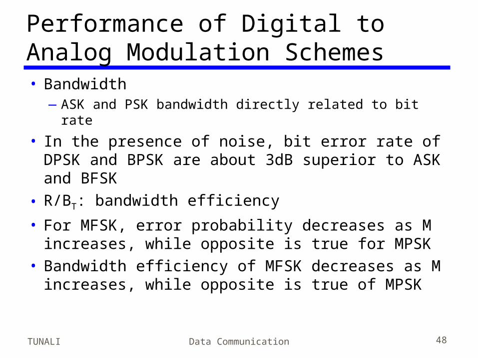
Performance of Digital to Analog Modulation Schemes• Bandwidth
—ASK and PSK bandwidth directly related to bit rate
• In the presence of noise, bit error rate of DPSK and BPSK are about 3dB superior to ASK and BFSK
• R/BT: bandwidth efficiency
• For MFSK, error probability decreases as M increases, while opposite is true for MPSK
• Bandwidth efficiency of MFSK decreases as M increases, while opposite is true of MPSK
TUNALI Data Communication 49
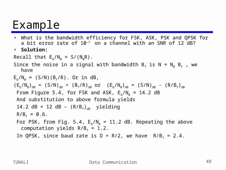
Example• What is the bandwidth efficiency for FSK, ASK, PSK and QPSK for a
bit error rate of 10-7 on a channel with an SNR of 12 dB?• Solution:
Recall that Eb/N0 = S/(N0R).
Since the noise in a signal with bandwidth BT is N = N0 BT , we have
Eb/N0 = (S/N)(BT/R). Or in dB,
(Eb/N0)dB = (S/N)dB + (BT/R)dB or (Eb/N0)dB = (S/N)dB - (R/BT)dB
From Figure 5.4, for FSK and ASK, Eb/N0 = 14.2 dB And substitution to above formula yields
14.2 dB = 12 dB – (R/BT)dB yielding
R/BT = 0.6.
For PSK, from Fig. 5.4, Eb/N0 = 11.2 dB. Repeating the above computation yields R/BT = 1.2.
In QPSK, since baud rate is D = R/2, we have R/BT = 2.4.
TUNALI Data Communication 50
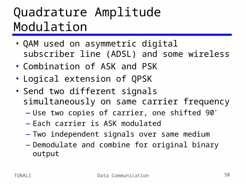
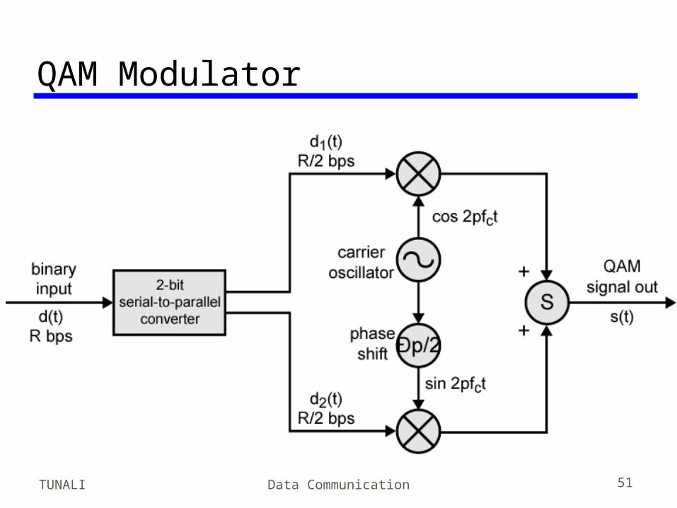
Quadrature Amplitude Modulation• QAM used on asymmetric digital subscriber
line (ADSL) and some wireless• Combination of ASK and PSK• Logical extension of QPSK• Send two different signals simultaneously
on same carrier frequency—Use two copies of carrier, one shifted 90°
—Each carrier is ASK modulated—Two independent signals over same medium—Demodulate and combine for original binary
output
TUNALI Data Communication 51
QAM Modulator
TUNALI Data Communication 52
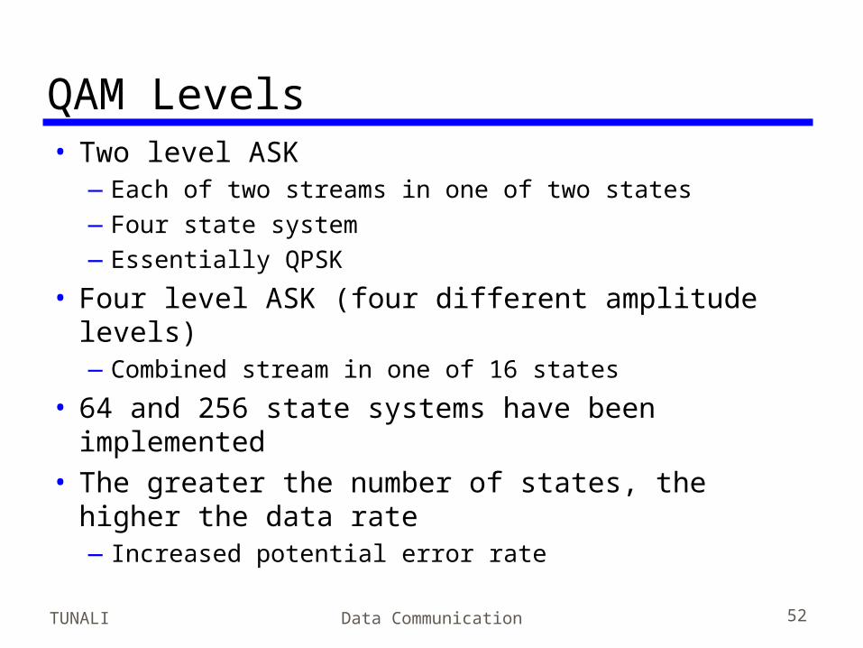
QAM Levels• Two level ASK
—Each of two streams in one of two states—Four state system—Essentially QPSK
• Four level ASK (four different amplitude levels)—Combined stream in one of 16 states
• 64 and 256 state systems have been implemented
• The greater the number of states, the higher the data rate—Increased potential error rate
TUNALI Data Communication 53
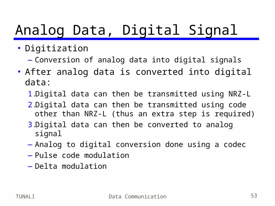
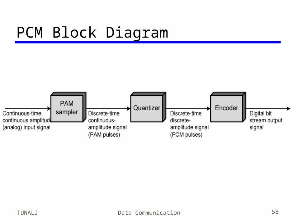
Analog Data, Digital Signal• Digitization
—Conversion of analog data into digital signals
• After analog data is converted into digital data: 1.Digital data can then be transmitted using NRZ-L2.Digital data can then be transmitted using code
other than NRZ-L (thus an extra step is required)3.Digital data can then be converted to analog signal—Analog to digital conversion done using a codec—Pulse code modulation—Delta modulation
TUNALI Data Communication 54
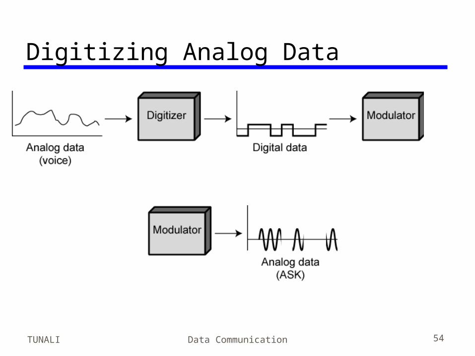
Digitizing Analog Data
TUNALI Data Communication 55
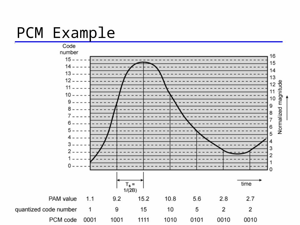
Pulse Code Modulation(PCM) (1)• Sample Theorem: If a signal is sampled
at regular intervals at a rate higher than twice the highest signal frequency, the samples contain all the information of the original signal
• Voice data limited to below 4000Hz• Require 8000 sample per second• Analog samples (Pulse Amplitude
Modulation, PAM)• Each sample assigned digital value
TUNALI Data Communication 56
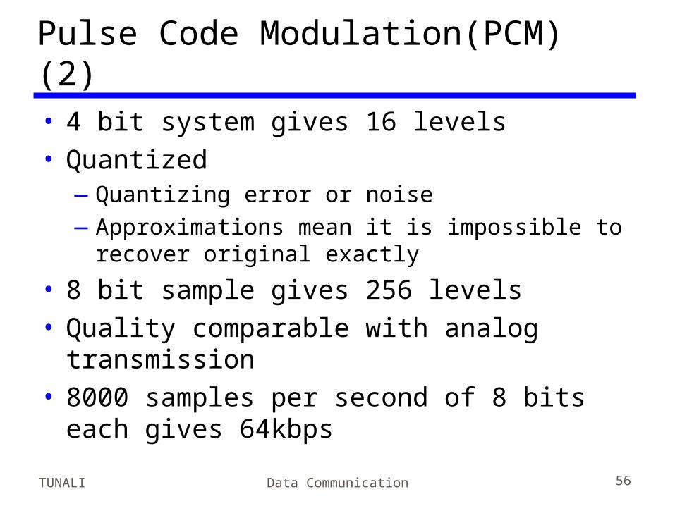
Pulse Code Modulation(PCM) (2)• 4 bit system gives 16 levels• Quantized
—Quantizing error or noise—Approximations mean it is impossible to
recover original exactly
• 8 bit sample gives 256 levels• Quality comparable with analog
transmission• 8000 samples per second of 8 bits each
gives 64kbps
TUNALI Data Communication 57
PCM Example
TUNALI Data Communication 58
PCM Block Diagram
TUNALI Data Communication 59
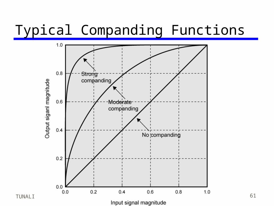
Nonlinear Encoding• Quantization levels not evenly spaced• Reduces overall signal distortion• Can also be done by companding• SNR for quantizing noise
—SNR = 6.02 n + 1.76 dB, where n is the number of bits representing each voltage level
• For voice signals, with nonlinear encoding, an improvement of 24 dB to 30 dB have been achieved.
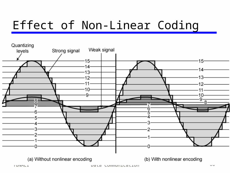
TUNALI Data Communication 60
Effect of Non-Linear Coding
TUNALI Data Communication 61
Typical Companding Functions
TUNALI Data Communication 62
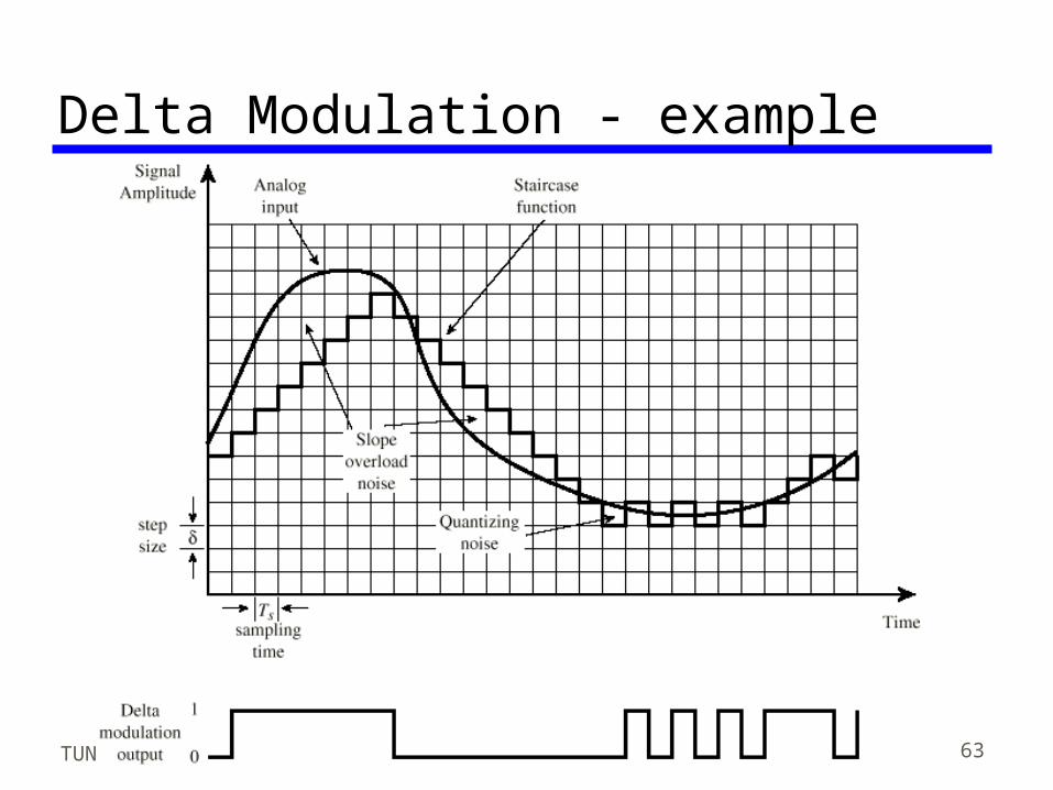
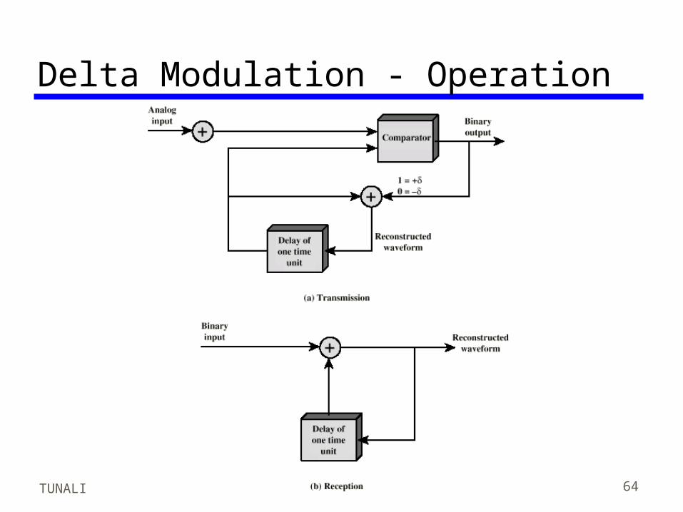
Delta Modulation• One of the most popular alternatives to
PCM• Analog input is approximated by a
staircase function• Move up or down one level () at each
sample interval• Binary behavior
—Function moves up or down at each sample interval
TUNALI Data Communication 63
Delta Modulation - example
TUNALI Data Communication 64
Delta Modulation - Operation
TUNALI Data Communication 65
Performance• Good voice reproduction
—PCM - 128 levels (7 bit)—Voice bandwidth 4khz—Should be 8000 x 7 = 56kbps for PCM
• Digital techniques continue to grow in popularity—Repeaters instead of amplifiers—TDM instead of FDM (intermodulation noise)—Efficient digital switching techniques
• Data compression can improve codecs—e.g. Interframe coding techniques for video
Performance• Use of a telecommunication system will
result in both digital-to analog and analog-to-digital processing—Local terminals into comm. network is analog and
network uses a mixture of analog and digital techniques
• Analog signals represents voice and digital data—Voice signals tend to be skewed lower portion of
the bandwidth—Because of the presence of higher frequencies,
PCM-related techniques is preferable to DM
TUNALI Data Communication 66
TUNALI Data Communication 67
Analog Data, Analog Signals• Why modulate analog signals?
—Higher frequency may be needed for efficient transmission
—Permits frequency division multiplexing (chapter 8)
• Types of modulation—Amplitude—Frequency—Phase
TUNALI Data Communication 68
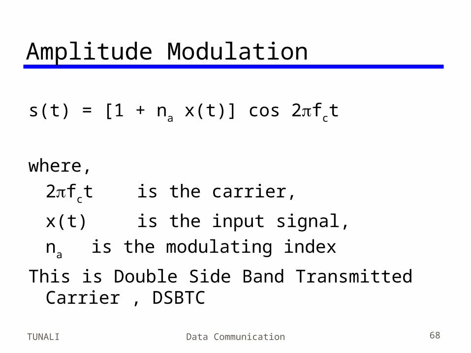
Amplitude Modulation
s(t) = [1 + na x(t)] cos 2fct
where, 2fct is the carrier,
x(t) is the input signal, na is the modulating index
This is Double Side Band Transmitted Carrier , DSBTC
TUNALI Data Communication 69
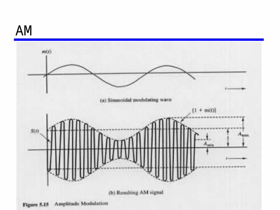
AM• Fig 5.15
TUNALI Data Communication 70
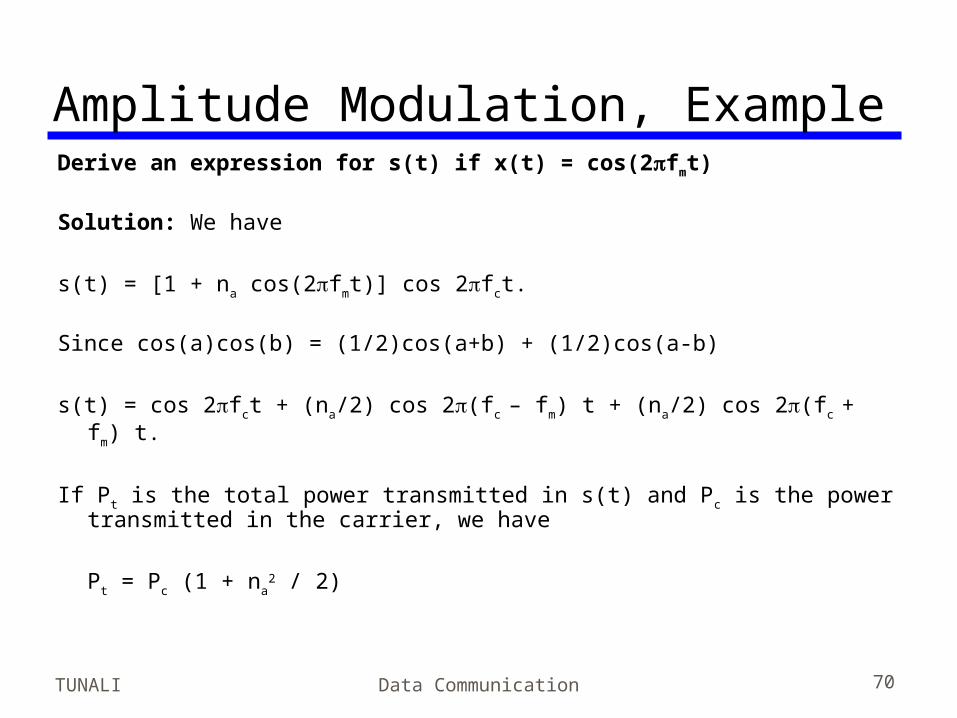
Amplitude Modulation, ExampleDerive an expression for s(t) if x(t) = cos(2fmt) Solution: We have
s(t) = [1 + na cos(2fmt)] cos 2fct. Since cos(a)cos(b) = (1/2)cos(a+b) + (1/2)cos(a-b)
s(t) = cos 2fct + (na/2) cos 2(fc – fm) t + (na/2) cos 2(fc + fm) t.
If Pt is the total power transmitted in s(t) and Pc is the power transmitted in the carrier, we have
Pt = Pc (1 + na2 / 2)
TUNALI Data Communication 71
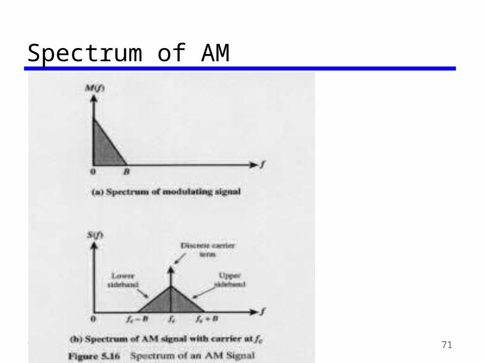
Spectrum of AM• Fig 5-16
TUNALI Data Communication 72
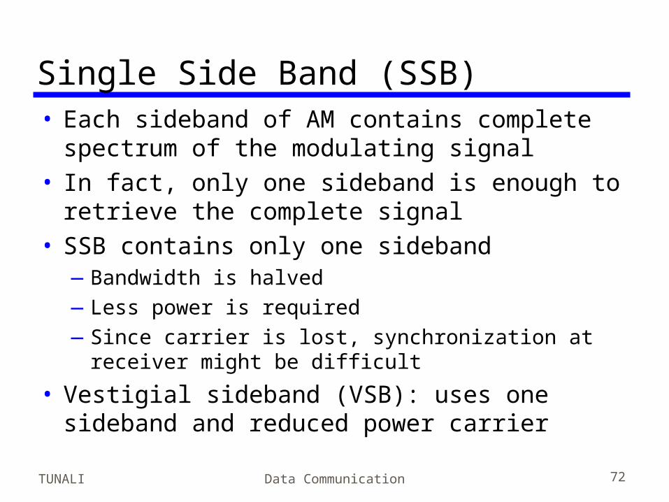
Single Side Band (SSB)• Each sideband of AM contains complete
spectrum of the modulating signal• In fact, only one sideband is enough to
retrieve the complete signal• SSB contains only one sideband
—Bandwidth is halved—Less power is required—Since carrier is lost, synchronization at receiver
might be difficult
• Vestigial sideband (VSB): uses one sideband and reduced power carrier
TUNALI Data Communication 73
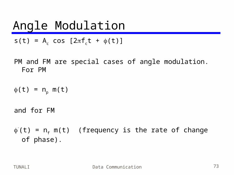
Angle Modulation s(t) = Ac cos [2fct + (t)]
PM and FM are special cases of angle modulation. For PM (t) = np m(t)
and for FM (t) = nf m(t) (frequency is the rate of change of phase).
TUNALI Data Communication 74
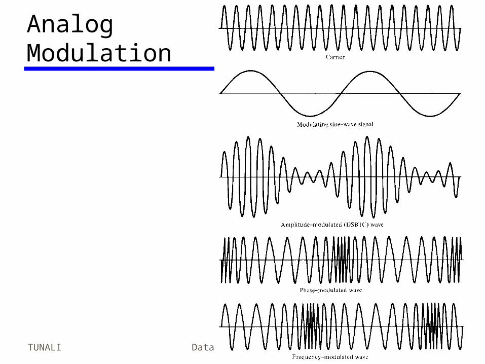
Analog Modulation
TUNALI Data Communication 75
BandwidthFor AM the bandwidth is given as BT = 2B
(where B is the bandwidth of the modulating signal),
For FM, the bandwidth is given as BT = 2B +
2F, where F is the peak frequency deviation. Both FM and PM require higher bandwidth than
AM.
TUNALI Data Communication 76
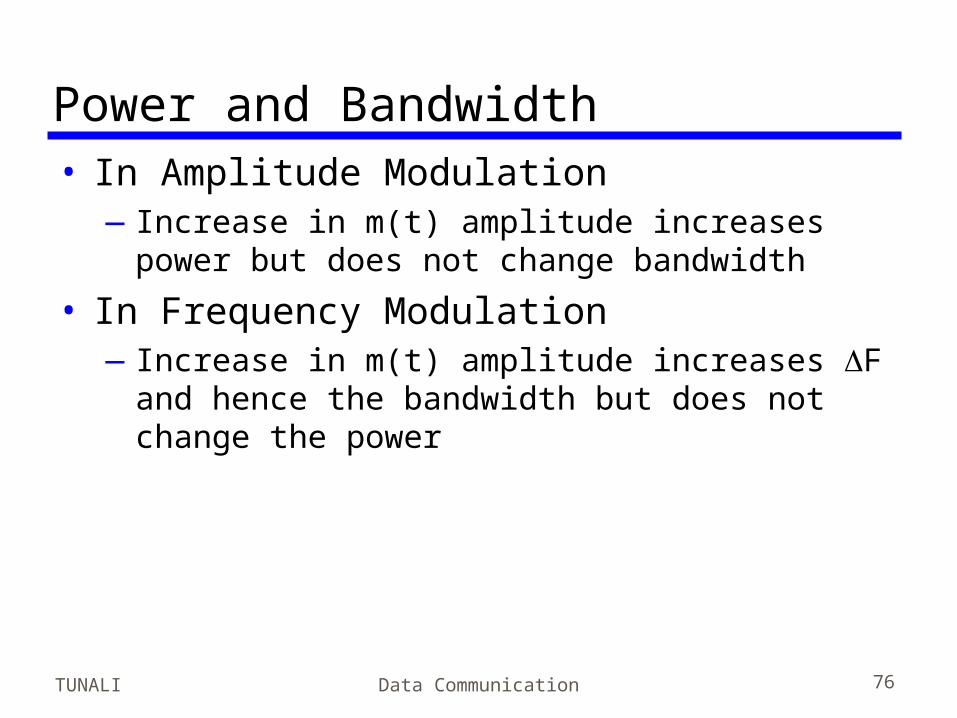
Power and Bandwidth• In Amplitude Modulation
—Increase in m(t) amplitude increases power but does not change bandwidth
• In Frequency Modulation—Increase in m(t) amplitude increases F and
hence the bandwidth but does not change the power
TUNALI Data Communication 77
Required Reading• Stallings chapter 5