Tunable Morphology of the Self-Assembled Organic...
7
Tunable Morphology of the Self-Assembled Organic Microcrystals for the Efficient Laser Optical Resonator by Molecular Modulation Xuedong Wang, †,‡ Hui Li, †,‡ Yishi Wu, † Zhenzhen Xu, § and Hongbing Fu* ,†,§ † Beijing National Laboratory for Molecular Sciences (BNLMS), Institute of Chemistry, Chinese Academy of Sciences, Beijing 100190, P. R. China ‡ Graduate University of Chinese Academy of Sciences, Beijing 100049, P. R. China § Department of Chemistry, Capital Normal University, Beijing 100048, P. R. China * S Supporting Information ABSTRACT: Organic single-crystalline micro/nanostructures can effectively generate and carry photons due to their smooth morphologies, high photoluminescence quantum efficiency, and minimized defects density and therefore are potentially ideal building blocks for the optical circuits in the next generation of miniaturized optoelectronics. However, the tailor-made organic molecules can be generally obtained by organic synthesis, ensuring that the organic molecules aggregate in a specific form and generate micro/nanostructures with desirable morphology and therefore act as the efficient laser optical resonator remains a great challenge. Here, the molecular modulation of the morphology on the laser optical resonator properties has been investigated through the preparation of the elongated hexagonal microplates (PHMs) and the rectangular microplates (ORMs), respectively, from two model isomeric organic molecules of 1,4-bis(4-methylstyryl)benzene (p-MSB) and 1,4-bis(2-methylstyryl)benzene (o- MSB). Significantly, fluorescence resonance phenomenon was only observed in the individual ORM other than the PHM. It indicates that the rectangular resonators possess better light-confinement property over the elongated hexagonal resonators. More importantly, optically pumped lasing action was observed in the o-MSB rectangular morphology microplates resonator with a high Q ≈ 1500 above a threshold of ∼540 nJ/cm 2 . The excellent optical properties of these microstructures are associated with the morphology, which can be precisely modulated by the organic molecular structure. These self-assembled organic microplates with different morphologies can contribute to the distinct functionality of photonics elements in the integrated optical circuits at micro/nanoscale. ■ INTRODUCTION The morphology of the semiconductor micro/nanostructures precisely lies at the heart of the physical and the chemical properties of the functional micro/nanomaterials. 1−5 For instance, M. A. EI-Sayed and co-workers demonstrated that Pt nanoparticles of different morphologies have different facets, which further led to the different catalytic activities for the same chemical reaction. 6 More significantly, the Ag nanocrystals with controlled morphologies have contributed to a distinguished discovery of morphology-dependent and size-dependent plasmon resonance. 7−9 As is indicated, the performance of these optoelectronic devices is attributed with the morphology of these micro/nanoscale fabricated structures. As compared with the inorganic/metal counterparts, small organic molecules are attractive photonic and electronic materials because of their tailor-made molecular structure, tunable optical properties, and compatibility with plastic substrates. 10 Especially the organic single-crystalline micro/nanostructures can effectively carry photons and electrons due to their perfect molecular arrangements, minimized defects, and eliminated grain boundaries in crystals 11 and therefore are potentially ideal building blocks for the miniaturized optoelectronics devi- ces. 12−16 Accordingly, highly ordered molecule packing mode is formed within the organic single-crystalline micro/nanocrystals, resulting in anisotropic charge transport in field effect Received: August 27, 2014 Published: November 4, 2014 Article pubs.acs.org/JACS © 2014 American Chemical Society 16602 dx.doi.org/10.1021/ja5088503 | J. Am. Chem. Soc. 2014, 136, 16602−16608 Downloaded by INST OF CHEMISTRY on August 25, 2015 | http://pubs.acs.org Publication Date (Web): November 12, 2014 | doi: 10.1021/ja5088503
Transcript of Tunable Morphology of the Self-Assembled Organic...

Tunable Morphology of the Self-Assembled Organic Microcrystalsfor the Efficient Laser Optical Resonator by Molecular ModulationXuedong Wang,†,‡ Hui Li,†,‡ Yishi Wu,† Zhenzhen Xu,§ and Hongbing Fu*,†,§
†Beijing National Laboratory for Molecular Sciences (BNLMS), Institute of Chemistry, Chinese Academy of Sciences, Beijing100190, P. R. China‡Graduate University of Chinese Academy of Sciences, Beijing 100049, P. R. China§Department of Chemistry, Capital Normal University, Beijing 100048, P. R. China
*S Supporting Information
ABSTRACT: Organic single-crystalline micro/nanostructures can effectively generate and carry photons due to their smoothmorphologies, high photoluminescence quantum efficiency, and minimized defects density and therefore are potentially idealbuilding blocks for the optical circuits in the next generation of miniaturized optoelectronics. However, the tailor-made organicmolecules can be generally obtained by organic synthesis, ensuring that the organic molecules aggregate in a specific form andgenerate micro/nanostructures with desirable morphology and therefore act as the efficient laser optical resonator remains a greatchallenge. Here, the molecular modulation of the morphology on the laser optical resonator properties has been investigatedthrough the preparation of the elongated hexagonal microplates (PHMs) and the rectangular microplates (ORMs), respectively,from two model isomeric organic molecules of 1,4-bis(4-methylstyryl)benzene (p-MSB) and 1,4-bis(2-methylstyryl)benzene (o-MSB). Significantly, fluorescence resonance phenomenon was only observed in the individual ORM other than the PHM. Itindicates that the rectangular resonators possess better light-confinement property over the elongated hexagonal resonators.More importantly, optically pumped lasing action was observed in the o-MSB rectangular morphology microplates resonator witha high Q ≈ 1500 above a threshold of ∼540 nJ/cm2. The excellent optical properties of these microstructures are associated withthe morphology, which can be precisely modulated by the organic molecular structure. These self-assembled organic microplateswith different morphologies can contribute to the distinct functionality of photonics elements in the integrated optical circuits atmicro/nanoscale.
■ INTRODUCTION
The morphology of the semiconductor micro/nanostructuresprecisely lies at the heart of the physical and the chemicalproperties of the functional micro/nanomaterials.1−5 Forinstance, M. A. EI-Sayed and co-workers demonstrated thatPt nanoparticles of different morphologies have different facets,which further led to the different catalytic activities for the samechemical reaction.6 More significantly, the Ag nanocrystals withcontrolled morphologies have contributed to a distinguisheddiscovery of morphology-dependent and size-dependentplasmon resonance.7−9 As is indicated, the performance ofthese optoelectronic devices is attributed with the morphologyof these micro/nanoscale fabricated structures. As comparedwith the inorganic/metal counterparts, small organic molecules
are attractive photonic and electronic materials because of theirtailor-made molecular structure, tunable optical properties, andcompatibility with plastic substrates.10 Especially the organicsingle-crystalline micro/nanostructures can effectively carryphotons and electrons due to their perfect moleculararrangements, minimized defects, and eliminated grainboundaries in crystals11 and therefore are potentially idealbuilding blocks for the miniaturized optoelectronics devi-ces.12−16 Accordingly, highly ordered molecule packing mode isformed within the organic single-crystalline micro/nanocrystals,resulting in anisotropic charge transport in field effect
Received: August 27, 2014Published: November 4, 2014
Article
pubs.acs.org/JACS
© 2014 American Chemical Society 16602 dx.doi.org/10.1021/ja5088503 | J. Am. Chem. Soc. 2014, 136, 16602−16608
Dow
nloa
ded
by I
NST
OF
CH
EM
IST
RY
on
Aug
ust 2
5, 2
015
| http
://pu
bs.a
cs.o
rg
Pub
licat
ion
Dat
e (W
eb):
Nov
embe
r 12
, 201
4 | d
oi: 1
0.10
21/ja
5088
503

transistors.17 What’s more, the single-crystalline organic micro/nanostructures with regular morphology have been demon-strated for the active media and the optical resonatorssimultaneously for the laser applications.18−20 However, thecontrolled synthesis of organic micro/nanostructures withdesirable morphologies has not been fully realized.21
As we all know, organic single-crystalline structuresfabricated from organic molecules are based on theintermolecular interaction, such as van der Waals’ force, ca. 5kJ/mol. It is totally different from the strong bondinginteraction, such as ionic bonding, ca. 200 kJ/mol, within theinorganic crystals. Thus, the outer environment including thekinds of solvents, temperature, solution concentration, andsurfactants can easily affect the nucleation of organic micro/nanocrystals. For the single organic molecule, these influencingfactors are so numerous and sophisticated that the aim oforganic micro/nanostructures with controlled morphology isnot easy to reach.22,23 It is noted that the flexibility in theorganic molecule synthesis and modification make them usefulfor the construction of various micro/nanostructures. More-over, the morphology−property relationship of organic micro/nanostructures has not been explored.24
Here, we take the ‘molecular modulation’ approach to obtainthe various morphologies of organic micro/nanostructures forthe efficient laser optical microresonators. The organicmolecules used in our study are the p-distyrylbenzene (DSB)derivatives 1,4-bis(2-methylstyryl)benzene (o-MSB) and 1,4-bis(4-methylstyryl)benzene (p-MSB), which have been dem-onstrated for the excellent amplified spontaneous emission(ASE) characteristics.25 The p-MSB elongated hexagonalmicroplates (PHMs) and o-MSB rectangular microplates(ORMs) from these two model π-conjugated isomeric organicmolecules have been fabricated by a facile bottom-upmethod.26−29 Importantly, fluorescence resonance phenomen-on was observed in the individual ORM other than PHM. Itindicates that the as-prepared o-MSB microplates withrectangular morphology possess better light-confinementproperty and higher quality (Q) factors over the p-MSBmicroplates with elongated hexagonal morphology. Further-more, optically pumped lasing action was only observed in theo-MSB rectangular microplate resonator with a high-qualityfactor (Q ≈ 1500) above a threshold of ∼540 nJ/cm2. Moresignificantly, by decreasing the size of o-MSB microplates,single-mode lasing was successfully achieved in the ORMs withsmall size (i.e., edge lengths l1 = 2.0 μm, and l2 = 1.8 μm).These self-assembled organic single-crystalline microplates withvarious morphologies are realized by molecular modulation,which open up the distinct functionality of organic photonics inthe integrated optical circuits.
■ EXPERIMENTAL SECTIONMaterials. The compounds of 1,4-bis(2-methylstyryl)benzene (o-
MSB) and 1,4-bis(4-methylstyryl)benzene (p-MSB) were purchasedfrom Sigma-Aldrich and were used without further treatment. Thesolvent of carbondisulfide (CS2, HPLC grade) was purchased fromBeijing Chemical Agent Ltd., China, and was used without furthertreatment.Preparation of Organic Microplates. In a typical synthesis, 2 mg
of p-MSB (o-MSB) was completely dissolved in 10 mL of CS2 at roomtemperature, and then the solution was dropped onto the quartzsubstrate. Finally the solvents evaporated, and the microstructureswere obtained in a large scale.Structure Characterization. TEM measurement was performed
at room temperature at an accelerating voltage of 100 kV.
Fluorescence images were recorded using an Olympus researchinverted system microscope (FV1000-IX81, Tokyo, Japan) equippedwith a charge couple device (CCD, Olympus DP71, Tokyo, Japan)camera. The excitation source is a mercury lamp equipped with aband-pass filter (330−380 nm for UV-light). The samples wereprepared by placing a drop of solution onto a cleaned quartz plate.
Micro-PL (μ-PL) Setup. The single-particle spectroscopy wasperformed by using a homemade optical microscope equipped with a50 × 0.9 NA objective (Supporting Information, Figure S4). Thesecond harmonic (λ = 400 nm, pulse width 150 fs) of a 1 kHzTi:sapphire regenerative amplifier was amplified to a 50 μm diameterspot to uniformly excite the selected isolated microcrystal on a 2Dmovable table. The spatially resolved PL spectra from singlemicroplate were collected underneath using a 3D-movable 100 × 0.9NA objective with a spatial resolution <1 μm. A 420 nm long-wavepass dielectric filter was used to block any scattered excitation light.Finally the collected PL was coupled to an optical fiber with diameter25/125 μm (core/cladding) and detected using a liquid-nitrogen-cooled CCD (SPEC-10-400B/LbN, Roper Scientific) attached to apolychromator (Spectropro-550i, Acton). This setup allows us tocharacterize single microplate and avoid the influence of other plates inthe excitation area.
■ RESULTS AND DISCUSSIONFigure 1A shows the chemical structure of these two modelisomeric π-conjugated small organic molecules 1,4-bis(4-
methylstyryl)benzene (p-MSB) and 1,4-bis(2-methylstyryl)-benzene (o-MSB), which are the simplified derivatives of p-distyrylbenzene (DSB). To know the molecular modulation ofthe crystal morphology based on the organic molecules, we firstsimulated the growth morphology of p-MSB and o-MSBcrystals based on the attachment energies using the Materials
Figure 1. (A) Two model isomeric π-conjugated organic molecules p-MSB and o-MSB derivatives of DSB. (B) The simulated growthmorphology of p-MSB molecules based on the attachment energies.(C) The simulated growth morphology of o-MSB molecules based onthe attachment energies. (D) The bright optical image of the PHMs ina large scale. (E) The bright optical images of the as-prepared ORMsin a large scale. The scale bars are both 10 μm.
Journal of the American Chemical Society Article
dx.doi.org/10.1021/ja5088503 | J. Am. Chem. Soc. 2014, 136, 16602−1660816603
Dow
nloa
ded
by I
NST
OF
CH
EM
IST
RY
on
Aug
ust 2
5, 2
015
| http
://pu
bs.a
cs.o
rg
Pub
licat
ion
Dat
e (W
eb):
Nov
embe
r 12
, 201
4 | d
oi: 1
0.10
21/ja
5088
503
Studio package.30 From the calculated results, the growthmorphology of p-MSB molecules is predicted as the elongatedhexagonal plate-like structure (Figure 1B). In contrast with p-MSB, o-MSB molecules are prone to form the rectangular plate-like structure, as shown in Figure 1C.In experiment, microstructures of p-MSB and o-MSB were
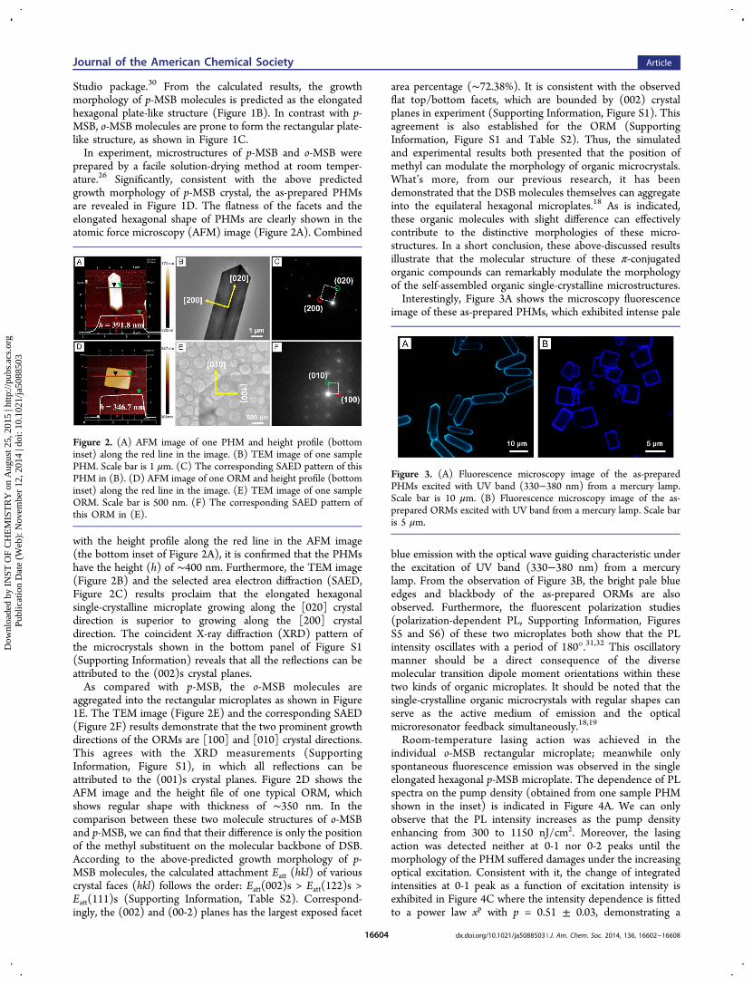
prepared by a facile solution-drying method at room temper-ature.26 Significantly, consistent with the above predictedgrowth morphology of p-MSB crystal, the as-prepared PHMsare revealed in Figure 1D. The flatness of the facets and theelongated hexagonal shape of PHMs are clearly shown in theatomic force microscopy (AFM) image (Figure 2A). Combined
with the height profile along the red line in the AFM image(the bottom inset of Figure 2A), it is confirmed that the PHMshave the height (h) of ∼400 nm. Furthermore, the TEM image(Figure 2B) and the selected area electron diffraction (SAED,Figure 2C) results proclaim that the elongated hexagonalsingle-crystalline microplate growing along the [020] crystaldirection is superior to growing along the [200] crystaldirection. The coincident X-ray diffraction (XRD) pattern ofthe microcrystals shown in the bottom panel of Figure S1(Supporting Information) reveals that all the reflections can beattributed to the (002)s crystal planes.As compared with p-MSB, the o-MSB molecules are
aggregated into the rectangular microplates as shown in Figure1E. The TEM image (Figure 2E) and the corresponding SAED(Figure 2F) results demonstrate that the two prominent growthdirections of the ORMs are [100] and [010] crystal directions.This agrees with the XRD measurements (SupportingInformation, Figure S1), in which all reflections can beattributed to the (001)s crystal planes. Figure 2D shows theAFM image and the height file of one typical ORM, whichshows regular shape with thickness of ∼350 nm. In thecomparison between these two molecule structures of o-MSBand p-MSB, we can find that their difference is only the positionof the methyl substituent on the molecular backbone of DSB.According to the above-predicted growth morphology of p-MSB molecules, the calculated attachment Eatt (hkl) of variouscrystal faces (hkl) follows the order: Eatt(002)s > Eatt(122)s >Eatt(111)s (Supporting Information, Table S2). Correspond-ingly, the (002) and (00-2) planes has the largest exposed facet
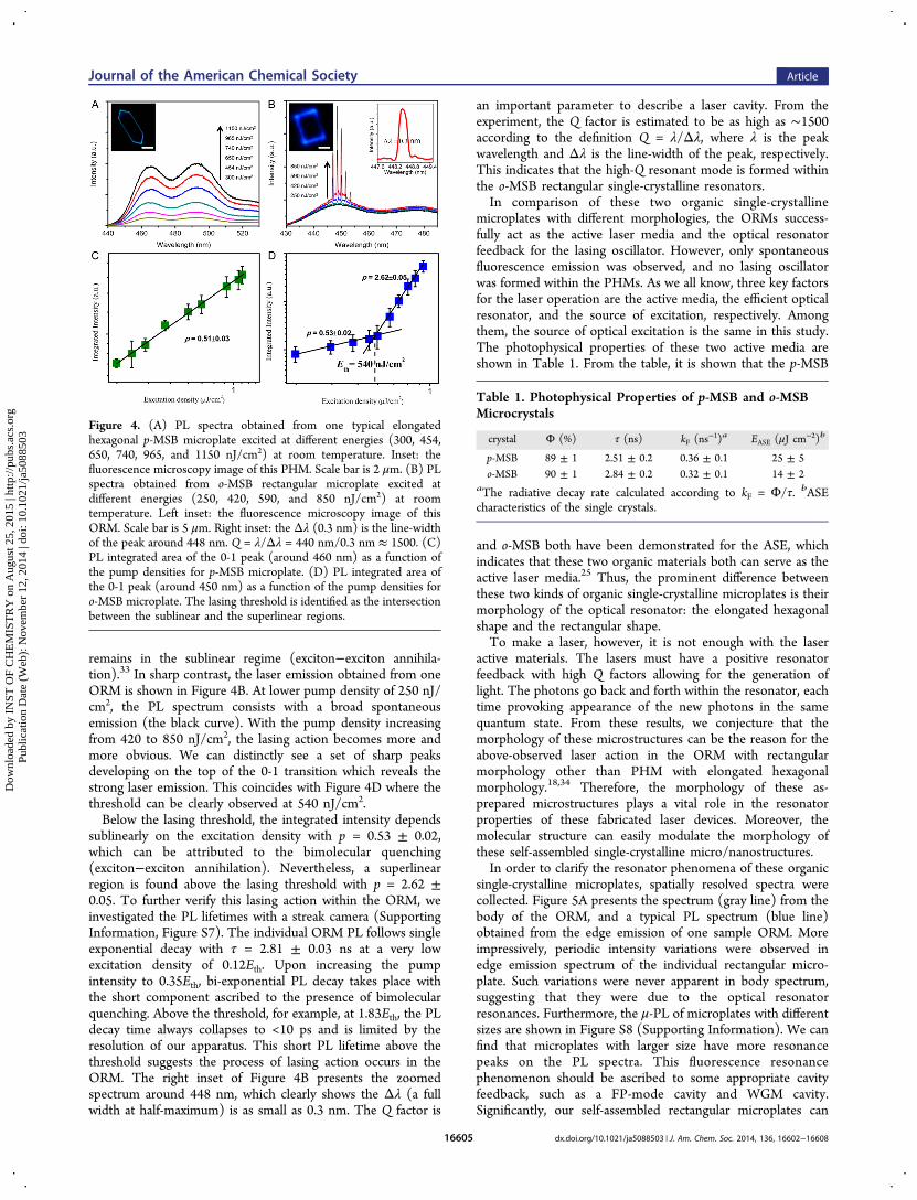
area percentage (∼72.38%). It is consistent with the observedflat top/bottom facets, which are bounded by (002) crystalplanes in experiment (Supporting Information, Figure S1). Thisagreement is also established for the ORM (SupportingInformation, Figure S1 and Table S2). Thus, the simulatedand experimental results both presented that the position ofmethyl can modulate the morphology of organic microcrystals.What’s more, from our previous research, it has beendemonstrated that the DSB molecules themselves can aggregateinto the equilateral hexagonal microplates.18 As is indicated,these organic molecules with slight difference can effectivelycontribute to the distinctive morphologies of these micro-structures. In a short conclusion, these above-discussed resultsillustrate that the molecular structure of these π-conjugatedorganic compounds can remarkably modulate the morphologyof the self-assembled organic single-crystalline microstructures.Interestingly, Figure 3A shows the microscopy fluorescence
image of these as-prepared PHMs, which exhibited intense pale
blue emission with the optical wave guiding characteristic underthe excitation of UV band (330−380 nm) from a mercurylamp. From the observation of Figure 3B, the bright pale blueedges and blackbody of the as-prepared ORMs are alsoobserved. Furthermore, the fluorescent polarization studies(polarization-dependent PL, Supporting Information, FiguresS5 and S6) of these two microplates both show that the PLintensity oscillates with a period of 180°.31,32 This oscillatorymanner should be a direct consequence of the diversemolecular transition dipole moment orientations within thesetwo kinds of organic microplates. It should be noted that thesingle-crystalline organic microcrystals with regular shapes canserve as the active medium of emission and the opticalmicroresonator feedback simultaneously.18,19
Room-temperature lasing action was achieved in theindividual o-MSB rectangular microplate; meanwhile onlyspontaneous fluorescence emission was observed in the singleelongated hexagonal p-MSB microplate. The dependence of PLspectra on the pump density (obtained from one sample PHMshown in the inset) is indicated in Figure 4A. We can onlyobserve that the PL intensity increases as the pump densityenhancing from 300 to 1150 nJ/cm2. Moreover, the lasingaction was detected neither at 0-1 nor 0-2 peaks until themorphology of the PHM suffered damages under the increasingoptical excitation. Consistent with it, the change of integratedintensities at 0-1 peak as a function of excitation intensity isexhibited in Figure 4C where the intensity dependence is fittedto a power law xp with p = 0.51 ± 0.03, demonstrating a
Figure 2. (A) AFM image of one PHM and height profile (bottominset) along the red line in the image. (B) TEM image of one samplePHM. Scale bar is 1 μm. (C) The corresponding SAED pattern of thisPHM in (B). (D) AFM image of one ORM and height profile (bottominset) along the red line in the image. (E) TEM image of one sampleORM. Scale bar is 500 nm. (F) The corresponding SAED pattern ofthis ORM in (E).
Figure 3. (A) Fluorescence microscopy image of the as-preparedPHMs excited with UV band (330−380 nm) from a mercury lamp.Scale bar is 10 μm. (B) Fluorescence microscopy image of the as-prepared ORMs excited with UV band from a mercury lamp. Scale baris 5 μm.
Journal of the American Chemical Society Article
dx.doi.org/10.1021/ja5088503 | J. Am. Chem. Soc. 2014, 136, 16602−1660816604
Dow
nloa
ded
by I
NST
OF
CH
EM
IST
RY
on
Aug
ust 2
5, 2
015
| http
://pu
bs.a
cs.o
rg
Pub
licat
ion
Dat
e (W
eb):
Nov
embe
r 12
, 201
4 | d
oi: 1
0.10
21/ja
5088
503
remains in the sublinear regime (exciton−exciton annihila-tion).33 In sharp contrast, the laser emission obtained from oneORM is shown in Figure 4B. At lower pump density of 250 nJ/cm2, the PL spectrum consists with a broad spontaneousemission (the black curve). With the pump density increasingfrom 420 to 850 nJ/cm2, the lasing action becomes more andmore obvious. We can distinctly see a set of sharp peaksdeveloping on the top of the 0-1 transition which reveals thestrong laser emission. This coincides with Figure 4D where thethreshold can be clearly observed at 540 nJ/cm2.Below the lasing threshold, the integrated intensity depends
sublinearly on the excitation density with p = 0.53 ± 0.02,which can be attributed to the bimolecular quenching(exciton−exciton annihilation). Nevertheless, a superlinearregion is found above the lasing threshold with p = 2.62 ±0.05. To further verify this lasing action within the ORM, weinvestigated the PL lifetimes with a streak camera (SupportingInformation, Figure S7). The individual ORM PL follows singleexponential decay with τ = 2.81 ± 0.03 ns at a very lowexcitation density of 0.12Eth. Upon increasing the pumpintensity to 0.35Eth, bi-exponential PL decay takes place withthe short component ascribed to the presence of bimolecularquenching. Above the threshold, for example, at 1.83Eth, the PLdecay time always collapses to <10 ps and is limited by theresolution of our apparatus. This short PL lifetime above thethreshold suggests the process of lasing action occurs in theORM. The right inset of Figure 4B presents the zoomedspectrum around 448 nm, which clearly shows the Δλ (a fullwidth at half-maximum) is as small as 0.3 nm. The Q factor is
an important parameter to describe a laser cavity. From theexperiment, the Q factor is estimated to be as high as ∼1500according to the definition Q = λ/Δλ, where λ is the peakwavelength and Δλ is the line-width of the peak, respectively.This indicates that the high-Q resonant mode is formed withinthe o-MSB rectangular single-crystalline resonators.In comparison of these two organic single-crystalline
microplates with different morphologies, the ORMs success-fully act as the active laser media and the optical resonatorfeedback for the lasing oscillator. However, only spontaneousfluorescence emission was observed, and no lasing oscillatorwas formed within the PHMs. As we all know, three key factorsfor the laser operation are the active media, the efficient opticalresonator, and the source of excitation, respectively. Amongthem, the source of optical excitation is the same in this study.The photophysical properties of these two active media areshown in Table 1. From the table, it is shown that the p-MSB
and o-MSB both have been demonstrated for the ASE, whichindicates that these two organic materials both can serve as theactive laser media.25 Thus, the prominent difference betweenthese two kinds of organic single-crystalline microplates is theirmorphology of the optical resonator: the elongated hexagonalshape and the rectangular shape.To make a laser, however, it is not enough with the laser
active materials. The lasers must have a positive resonatorfeedback with high Q factors allowing for the generation oflight. The photons go back and forth within the resonator, eachtime provoking appearance of the new photons in the samequantum state. From these results, we conjecture that themorphology of these microstructures can be the reason for theabove-observed laser action in the ORM with rectangularmorphology other than PHM with elongated hexagonalmorphology.18,34 Therefore, the morphology of these as-prepared microstructures plays a vital role in the resonatorproperties of these fabricated laser devices. Moreover, themolecular structure can easily modulate the morphology ofthese self-assembled single-crystalline micro/nanostructures.In order to clarify the resonator phenomena of these organic
single-crystalline microplates, spatially resolved spectra werecollected. Figure 5A presents the spectrum (gray line) from thebody of the ORM, and a typical PL spectrum (blue line)obtained from the edge emission of one sample ORM. Moreimpressively, periodic intensity variations were observed inedge emission spectrum of the individual rectangular micro-plate. Such variations were never apparent in body spectrum,suggesting that they were due to the optical resonatorresonances. Furthermore, the μ-PL of microplates with differentsizes are shown in Figure S8 (Supporting Information). We canfind that microplates with larger size have more resonancepeaks on the PL spectra. This fluorescence resonancephenomenon should be ascribed to some appropriate cavityfeedback, such as a FP-mode cavity and WGM cavity.Significantly, our self-assembled rectangular microplates can
Figure 4. (A) PL spectra obtained from one typical elongatedhexagonal p-MSB microplate excited at different energies (300, 454,650, 740, 965, and 1150 nJ/cm2) at room temperature. Inset: thefluorescence microscopy image of this PHM. Scale bar is 2 μm. (B) PLspectra obtained from o-MSB rectangular microplate excited atdifferent energies (250, 420, 590, and 850 nJ/cm2) at roomtemperature. Left inset: the fluorescence microscopy image of thisORM. Scale bar is 5 μm. Right inset: the Δλ (0.3 nm) is the line-widthof the peak around 448 nm. Q = λ/Δλ = 440 nm/0.3 nm ≈ 1500. (C)PL integrated area of the 0-1 peak (around 460 nm) as a function ofthe pump densities for p-MSB microplate. (D) PL integrated area ofthe 0-1 peak (around 450 nm) as a function of the pump densities foro-MSB microplate. The lasing threshold is identified as the intersectionbetween the sublinear and the superlinear regions.
Table 1. Photophysical Properties of p-MSB and o-MSBMicrocrystals
crystal Φ (%) τ (ns) kF (ns−1)a EASE (μJ cm
−2)b
p-MSB 89 ± 1 2.51 ± 0.2 0.36 ± 0.1 25 ± 5o-MSB 90 ± 1 2.84 ± 0.2 0.32 ± 0.1 14 ± 2
aThe radiative decay rate calculated according to kF = Φ/τ. bASEcharacteristics of the single crystals.
Journal of the American Chemical Society Article
dx.doi.org/10.1021/ja5088503 | J. Am. Chem. Soc. 2014, 136, 16602−1660816605
Dow
nloa
ded
by I
NST
OF
CH
EM
IST
RY
on
Aug
ust 2
5, 2
015
| http
://pu
bs.a
cs.o
rg
Pub
licat
ion
Dat
e (W
eb):
Nov
embe
r 12
, 201
4 | d
oi: 1
0.10
21/ja
5088
503

simultaneously act as the active medium of laser emission andthe optical resonator feedback. To form a stable oscillator in theresonator and make light waves strengthened due tointerference, the phase change for the light going a roundtrip in the resonator should be an integer of 2π, i.e., theresonance condition:
λ=nL m (1)
where n, L are the phase refractive index of the crystal andround-trip distance, respectively, and m is the order of themode (an integer). Restricted by the condition, only certainfrequencies of light are ultimately chosen and enhanced by theoptical resonator. Thus, a set of sharp peaks with certainfrequencies was observed in the PL spectra of ORNs. For theFP-mode cavity, it can be formed either by the top and bottomrectangular facets (Supporting Information, Figure S9A) or bytwo opposing edge facets of ORM (Figure S9B).35,36
This ORM resonator can also support 4-WGM (the left insetof Figure 5B), where the light is totally reflected by the fourlateral sides of the rectangular microplate.18 The zoomedspectrum (from 446 to 454 nm) shows the distance betweentwo adjacent peaks around 450 nm is 1.6 nm (the right inset ofFigure 5A), which is as the definition of mode spacing Δλm.Further Δλm can be expressed as eq 2:
λ λλ λ
Δ =−L n n[ (d /d )]m
2
(2)
where n is the phase refractive index of the crystal (n = 1.8), Lis the round-trip distance of a cavity mode, dn/dλ is the
dispersion relation. The round-trip distance L within the 4-WGM resonators could be defined as the following expression:
= +L l l2 12
22
(3)
where l1 and l2 are the edge lengths of the rectangularmicroplates. Figure 5B presents a plot of the mode spacing Δλmat λ of ∼450 nm versus 1/L within the 4-WGM cavity,demonstrating clearly a linear relationship. This linear relation-ship is consistent with that the light travels in the form of 4-WGM rather than other forms in the rectangular resonator.37
To further know the mechanism of the cavity mode within theORM, the electromagnetic field distribution of the rectangularresonator was simulated, as shown in Figure 5C. The calculatedresult presents that the o-MSB rectangular resonator providesexcellent confinement for the electromagnetic field. Further-more, we calculated the quality (Q) factors corresponding tothis ORM resonator. Figure 5D shows that there exist severalhigh-Q modes (∼20000) in the ORM. These high-Q modescan explain the above-observed WGM laser in the ORMs.As mentioned above, the ORMs with rectangular morphol-
ogy can provide multimode lasing. As compared withmultimode lasing, single-mode lasing has its inherent meritsas excellent monochrome properties of laser beam, fine opticalcoherence, and good stability of laser oscillation due to theabsent of mode competition. In principle, the gain of lasingaction is determined by the spatial spectra and the spectraloverlap between the resonance and the gain material.38 It alsomeans that smaller resonator provides less resonance states. Inexperiment, Figure 6A presents the three lasing spectra
sequentially from top to bottom, from three sample ORMswith sizes varying from l1 = 7.7 μm, l2 = 6.9 μm; to l1 = 4.2 μm,l2 = 3.5 μm; and to l1 = 2.0 μm, l2 = 1.8 μm. It should be notedhere that the lasing spectra are collected from the wholemicroplate. Under high optical excitation density above thelasing threshold, such as 3.5Eth, the lasing mode (or stimulatedemission) completely dominates the PL spectrum, while the
Figure 5. (A) μ-PL spectra of one single ORM. Top inset: the PLmicroscopy image of the sample ORM, the yellow square rectangularline denotes the edge region, and the red circle dashed line denotes thebody region. Scale bar is 5 μm. Emission spectra collected from theedge region (blue line) and body region (gray line) of this isolated o-MSB rectangular microplate. Right inset: the magnification ofspectrum around 450 nm. (B) The mode spacing Δλm at 450 nm(0-1) and 1/L of the resonator, showing clearly a linear relationship.Inset: schematic picture of the light-path of the 4-WGM in therectangular resonator. (C) Simulated 2D normalized electric field(surface: electric field norm (V/m), λ = 450 nm, n = 1.80) of the o-MSB rectangular resonator. (D) Simulated 2D normalized electricfield (surface: electric field norm (V/m), λ = 450 nm, n = 1.80) of thep-MSB elongated hexagonal resonator.
Figure 6. (A) Laser spectra of three rectangular microplates withdifferent sizes (l1 = 7.7 μm, l2 = 6.9 μm; l1 = 4.2 μm, l2 = 3.5 μm; and l1= 2.0 μm, l2 = 1.8 μm). (B−D) Simulated 2D normalized electric field(λ = 450 nm, n = 1.80) in the plane of these three correspondingmicroplates resonators. The ORMs with different sizes can all providethe efficient WGM optical resonators for lasing oscillator. Redcorresponds to the highest field density, and blue is the lowest fielddensity.
Journal of the American Chemical Society Article
dx.doi.org/10.1021/ja5088503 | J. Am. Chem. Soc. 2014, 136, 16602−1660816606
Dow
nloa
ded
by I
NST
OF
CH
EM
IST
RY
on
Aug
ust 2
5, 2
015
| http
://pu
bs.a
cs.o
rg
Pub
licat
ion
Dat
e (W
eb):
Nov
embe
r 12
, 201
4 | d
oi: 1
0.10
21/ja
5088
503

spontaneous emission remains at low intensity. Thus, as seenfrom Figure 6A, only lasing resonance peaks are observed in thePL spectra. As in the ORM with small size (l1 = 2.0 μm, l2 = 1.8μm), single-mode lasing was successfully achieved at roomtemperature. It is that the single-crystalline nature of thesemicroplates contributes to the high density of optical gain,which can account for the observed laser action within ORMwith such small size. Figure 6B−D demonstrates the simulatedelectromagnetic distribution of these three correspondingORMs resonators. The simulation results indicate that theORMs with different sizes can all act as the efficient WGMoptical resonators for lasing oscillator.In practice, these as-prepared ORMs are not absolutely
uniform. As indicated in Figure S9 (Supporting Information),the quality factors Q of these rectangular geometries (squareresonators or rectangular resonators) are all larger than 1500,which promises the efficient optical resonator for the laseroperation. Among these geometries, the square ORM resonatorhas the largest Q of ∼6700. Moreover, the simulated electricfield distribution of square optical resonator (such as edgelengths l1 = 4 um, and l2 = 4 um) shows the excellent lightconfinement. Meanwhile, the rectangular microplates (such asl1 = 5 um, and l2 = 3 um) can still confine the electric field inthe rectangular optical resonator. Thus, the o-MSB rectangularmicroplates (ORMs) can all provide the efficient opticalresonator for laser operation.In a sharp contrast, a μ-PL spectrum (red line) of the edge
emission of the individual PHM shows no resonancephenomenon as the PL spectrum (green line) of the bodyhas (Figure 7A). It illustrates that the PHM cannot act as anefficient optical resonator. To further know the light-confine-ment properties in individual PHM, we simulated theelectromagnetic field distribution of the hexagonal resonatorswith different morphologies (Figure 7B). The right top inset ofFigure 7B shows that d1 and d2 are the long edge and the shortedge of the elongated hexagonal microplates, respectively. Thed1/d2 is defined as the ratio η, and the sum of d1 and d2 isdefined as a constant value of 10 μm. The calculated Q of theoptical resonator versus the ratio η is plotted in Figure 7B. Aswe can see, the Q factor decreases dramatically with theincreasing value of η. When η = 1, the resonator is theequilateral hexagonal resonator. This regular hexagonalresonator indeed provides the excellent light confinementwith the high-Q mode of ∼2500, as indicated by the electricfield distribution (left top inset of Figure 7B). This simulatedhigh-Q mode is also consistent with our previous observation ofWGM microlaser within the DSB equilateral hexagonalmicrodisks.18 Again the resonator with high-Q has beendemonstrated for the operation of lasing oscillator.In the case of PHMs with elongated hexagonal morphology
(η = 3, red circle), the bottom inset of Figure 7B demonstratesthat the electromagnetic field distribution both exists within thehexagonal resonator and in the surroundings, which meanspoor light confinement in this PHM resonator with low-Qmodes (Q ≈ 100) by simulation. As is known to us, higher Qindicates a lower rate of energy loss relative to the storedenergy of the resonator and the oscillations die out moreslowly.32 It also means that high-Q resonator provides theeffective platform for the laser action. Thus, the elongatedhexagonal morphology accounts for the low-Q modes and theabsence of laser action in the individual PHMs. As comparedwith PHMs, the ORMs with rectangular morphology inherentlyhave the high-Q modes, which hold the promise for the laser
action. In a short conclusion, the light-confinement property(Q) can be attributed with the morphology of these self-assembled single-crystalline organic microstructures. Moreimportantly, the morphology of these microstructures can beprecisely modulated by the organic molecular structure.
■ CONCLUSIONIn summary, the molecular modulation of the morphology onthe organic optical microresonator properties has beeninvestigated through the preparation of elongated hexagonalmicroplates and rectangular microplates from two modelisomeric molecules of 1,4-bis(4-methylstyryl)benzene (p-MSB) and 1,4-bis(2-methylstyryl)benzene (o-MSB), respec-tively. Impressively, fluorescence resonance phenomenon wasobserved in the individual o-MSB rectangular microplate(ORM) rather than the p-MSB elongated hexagonal microplate(PHM). It indicates that the ORMs with rectangularmorphology possess better light-confinement property andhigher quality (Q) factors over the PHMs with elongatedhexagonal morphology. More significantly, optically pumped
Figure 7. (A) μ-PL spectra of one typical PHM. Right inset: redrectangular dashed line denotes the edge region, and the yellow squaredashed line denotes the body region. Scale bar is 5 μm. PL spectracollected from the edge (red line) and body (green line) of an isolatedPHM. (B) Quality factors Q dependence of the shape of the elongatedhexagonal microplate. Right top inset: d1 and d2 are the long edge andthe short edge of the elongated hexagonal microplate, respectively.The ratio η is defined as d1/d2, and the sum of d1 and d2 equals aconstant value of 10 μm. Left top inset: simulated 2D normalizedelectric field (surface: electric field norm (V/m), λ = 460 nm, n = 1.80)of the normal hexagonal resonator corresponding to the η = 1(denoted by the green circle). Bottom inset: simulated 2D normalizedelectric field (surface: electric field norm (V/m), λ = 460 nm, n = 1.80)of elongated p-MSB hexagonal resonator corresponding to the η = 3(denoted by the red circle) in the case of PHMs. Red corresponds tothe highest field density, and blue is the lowest field density.
Journal of the American Chemical Society Article
dx.doi.org/10.1021/ja5088503 | J. Am. Chem. Soc. 2014, 136, 16602−1660816607
Dow
nloa
ded
by I
NST
OF
CH
EM
IST
RY
on
Aug
ust 2
5, 2
015
| http
://pu
bs.a
cs.o
rg
Pub
licat
ion
Dat
e (W
eb):
Nov
embe
r 12
, 201
4 | d
oi: 1
0.10
21/ja
5088
503

lasing action was only observed in the ORM with a high qualityfactor Q of ∼1500 above a lasing threshold of ∼540 nJ/cm2. Bydecreasing the size of ORMs, single-mode lasing wassuccessfully achieved in the ORMs with small size (i.e., edgelengths l1 = 2.0 μm, and l2 = 1.8 μm). Thus, the molecule−morphology−property relationship was successfully establishedfor these self-assembled organic single-crystalline microplates.These self-assembled organic microplates with differentmorphologies are natural light sources with distinctiveproperties, which could be integrated on the optics chip atmicro/nanoscale.
■ ASSOCIATED CONTENT*S Supporting InformationXRD patterns of the as-prepared microstructures; crystallo-graphic data of the single crystals; the calculated attachmentenergies Eatt of various crystal facets; schematic illustration ofthe near-field scanning optical microscopy; absorption andfluorescence spectra; μ-PL spectra of ORMs with differentsizes; fluorescence delay files; fluorescent polarization study ofmicroplates; the schematic pictures of two kinds of FP-modecavity; and the shape-dependent quality factors of ORMs. Thismaterial is available free of charge via the Internet at http://pubs.acs.org/.
■ AUTHOR INFORMATIONCorresponding [email protected]
NotesThe authors declare no competing financial interest.
■ ACKNOWLEDGMENTSThis work was supported by the National Natural ScienceFoundation of China (nos. 21073200, 21273251, 91333111,21190034, 21221002), Beijing Municipal Science & Technol-ogy Commission (no. Z131103002813097), project ofConstruction of Innovative Teams and Teacher CareerDevelopment for Universities and Colleges Under BeijingMunicipality (IDHT20140512), the National Basic ResearchProgram of China (973) 2011CB808402, 2013CB933500, andthe Chinese Academy of Sciences.
■ REFERENCES(1) Choi, H. C.; Park, J. E.; Park, C. Acc. Chem. Res. 2014, 47, 2353.(2) Senyuk, B.; Evans, J. S.; Ackerman, P. J.; Lee, T.; Manna, P.;Vigderman, L.; Zubarev, E. R.; van de Lagemaat, J.; Smalyukh, I. I.Nano Lett. 2012, 12, 955.(3) Chandrasekhar, N.; Chandrasekar, R. Angew. Chem., Int. Ed. 2012,51, 3556.(4) Aslam, F.; von Ferber, C. Chem. Phys. 2009, 362, 114.(5) Ray, P. C. Chem. Rev. 2010, 110, 5332.(6) Narayanan, R.; El-Sayed, M. A. Nano Lett. 2004, 4, 1343.(7) Orendorff, C. J.; Sau, T. K.; Murphy, C. J. Small 2006, 2, 636.(8) Jin, R.; Cao, Y.; Mirkin, C. A.; Kelly, K. L.; Schatz, G. C.; Zheng,J. G. Science 2001, 294, 1901.(9) Nehl, C. L.; Hafner, J. H. J. Mater. Chem. 2008, 18, 2415.(10) Clark, J.; Lanzani, G. Nat. Photonics 2010, 4, 438.(11) Zhao, Y. S.; Fu, H. B.; Peng, A. D.; Ma, Y.; Liao, Q.; Yao, J. N.Acc. Chem. Res. 2010, 43, 409.(12) An, B. K.; Gihm, S. H.; Chung, J. W.; Park, C. R.; Kwon, S. K.;Park, S. Y. J. Am. Chem. Soc. 2009, 131, 3950.(13) Takazawa, K.; Inoue, J.-i.; Mitsuishi, K.; Takamasu, T. Phys. Rev.Lett. 2010, 105, 067401.
(14) Kong, Q.; Liao, Q.; Xu, Z.; Wang, X.; Yao, J.; Fu, H. J. Am.Chem. Soc. 2014, 136, 2382.(15) Wang, X.; Liao, Q.; Xu, Z.; Wu, Y.; Wei, L.; Lu, X.; Fu, H. ACSPhotonics 2014, 1, 413.(16) Zhao, Y.; Peng, A.; Fu, H.; Ma, Y.; Yao, J. Adv. Mater. 2008, 20,1661.(17) Sundar, V. C.; Zaumseil, J.; Podzorov, V.; Menard, E.; Willett, R.L.; Someya, T.; Gershenson, M. E.; Rogers, J. A. Science 2004, 303,1644.(18) Wang, X.; Liao, Q.; Kong, Q.; Zhang, Y.; Xu, Z.; Lu, X.; Fu, H.Angew. Chem. 2014, 126, 5973; Angew. Chem., Int. Ed. 2014, 53, 5863.(19) Xu, Z.; Liao, Q.; Shi, Q.; Zhang, H.; Yao, J.; Fu, H. Adv. Mater.2012, 24, OP216.(20) Zhang, C.; Zou, C. L.; Yan, Y.; Hao, R.; Sun, F. W.; Han, Z. F.;Zhao, Y. S.; Yao, J. J. Am. Chem. Soc. 2011, 133, 7276.(21) Kang, L.; Fu, H.; Cao, X.; Shi, Q.; Yao, J. J. Am. Chem. Soc. 2011,133, 1895.(22) Zhang, X.; Zhang, X.; Zou, K.; Lee, C. S.; Lee, S. T. J. Am. Chem.Soc. 2007, 129, 3527.(23) Liu, H.; Cao, X.; Wu, Y.; Liao, Q.; Jimenez, A. J.; Wurthner, F.;Fu, H. Chem. Commun. 2014, 50, 4620.(24) Wang, Y.; Fu, H.; Peng, A.; Zhao, Y.; Ma, J.; Ma, Y.; Yao, J.Chem. Commun. 2007, 16, 1623.(25) Kabe, R.; Nakanotani, H.; Sakanoue, T.; Yahiro, M.; Adachi, C.Adv. Mater. 2009, 21, 4034.(26) Wei, L.; Yao, J.; Fu, H. ACS Nano 2013, 7, 7573.(27) Kang, L.; Wang, Z.; Cao, Z.; Ma, Y.; Fu, H.; Yao, J. J. Am. Chem.Soc. 2007, 129, 7305.(28) Lei, Y.; Liao, Q.; Fu, H.; Yao, J. J. Phys. Chem. C 2009, 113,10038.(29) Huang, L.; Liao, Q.; Shi, Q.; Fu, H.; Ma, J.; Yao, J. J. Mater.Chem. 2010, 20, 159.(30) Winn, D.; Doherty, M. F. AIChE J. 2000, 46, 1348.(31) Chandrasekhar, N.; Basak, S.; Mohiddon, M. A.; Chandrasekar,R. ACS Appl. Mater. Interfaces 2014, 6, 1488.(32) Chandrasekar, R. Phys. Chem. Chem. Phys. 2014, 16, 7173.(33) Kena-Cohen, S.; Forrest, S. R. Nat. Photonics 2010, 4, 371.(34) Tamboli, A. C.; Haberer, E. D.; Sharma, R.; Lee, K. H.;Nakamura, S.; Hu, E. L. Nat. Photonics 2007, 1, 61.(35) Chen, R.; Ling, B.; Sun, X. W.; Sun, H. D. Adv. Mater. 2011, 23,2199.(36) Yoon, S. M.; Lee, J.; Je, J. H.; Choi, H. C.; Yoon, M. ACS Nano2011, 5, 2923.(37) O’Carroll, D.; Lieberwirth, I.; Redmond, G. Nat. Nanotechnol.2007, 2, 180.(38) Chen, R.; Van Duong, T.; Sun, H. D. Sci. Rep. 2012, 2, 244.
Journal of the American Chemical Society Article
dx.doi.org/10.1021/ja5088503 | J. Am. Chem. Soc. 2014, 136, 16602−1660816608
Dow
nloa
ded
by I
NST
OF
CH
EM
IST
RY
on
Aug
ust 2
5, 2
015
| http
://pu
bs.a
cs.o
rg
Pub
licat
ion
Dat
e (W
eb):
Nov
embe
r 12
, 201
4 | d
oi: 1
0.10
21/ja
5088
503