tugas bhs inggris.ppt
26
Sensors used in EFI (Electronic Fuel Injection) Prof.H.Abdul Rosyid.MT MODEM, WONDEM, DE nMA rK
-
Upload
anton-wicaksana -
Category
Documents
-
view
224 -
download
0
Transcript of tugas bhs inggris.ppt

7/27/2019 tugas bhs inggris.ppt
http://slidepdf.com/reader/full/tugas-bhs-inggrisppt 1/26
Sensors used in EFI(Electronic Fuel Injection)
Prof.H.Abdul Rosyid.MT
MODEM, WONDEM, DEnMA rK

7/27/2019 tugas bhs inggris.ppt
http://slidepdf.com/reader/full/tugas-bhs-inggrisppt 2/26
What is EFI?
• EFI is a way of delivering fuell to theengine by electronically controlling
injection directly into the intakemanifold near the intake valve

7/27/2019 tugas bhs inggris.ppt
http://slidepdf.com/reader/full/tugas-bhs-inggrisppt 3/26
History of EFI
• Carburetors are used to mix air andfuel,
• In 1979/80 Toyota introduced EFI,
• By 1991 the carburetor is eliminated,
• Reasons for switch:
– Superior emissions control,
– Better fuel economy,
– Improved vehicle performance

7/27/2019 tugas bhs inggris.ppt
http://slidepdf.com/reader/full/tugas-bhs-inggrisppt 4/26
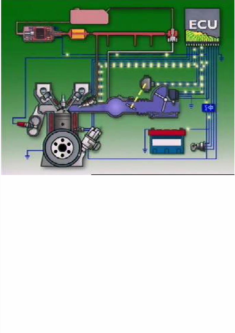
How EFI Works?
• There are three sub-systems in EFI
– the fuel delivery system
– air induction system
– the electronic control system
7/27/2019 tugas bhs inggris.ppt
http://slidepdf.com/reader/full/tugas-bhs-inggrisppt 5/26

7/27/2019 tugas bhs inggris.ppt
http://slidepdf.com/reader/full/tugas-bhs-inggrisppt 6/26
Fuel Delivery System
• This system consist of the:
– fuel tank,
– fuel pump,
– fuel filter,
– fuel delivery pipe,
– fuel injector, – fuel pressure regulator, and
– fuel return pipe.

7/27/2019 tugas bhs inggris.ppt
http://slidepdf.com/reader/full/tugas-bhs-inggrisppt 7/26
The Air Induction System
• This system consist of the:
– air cleaner,
– AIR FLOW METER
– throttle valve,
– air intake chamber,
– intake manifold runner, and – intake valve.

7/27/2019 tugas bhs inggris.ppt
http://slidepdf.com/reader/full/tugas-bhs-inggrisppt 8/26
Electronic Control System
• This system consist of the:
– Various engine SENSORS,
– Electronic Control Unit (ECU),
– Fuel injector assemblies, and related wiring
– The ECU determines precisely how much
fuel needs to be delivered by the injectorbased on the engine SENSORS output.Injector is turned On for the preciseamount of time to deliver proper air/fuel
ratio to the engine.

7/27/2019 tugas bhs inggris.ppt
http://slidepdf.com/reader/full/tugas-bhs-inggrisppt 9/26
Basic Operation of ECUSystem
• Air enters the engine andthen measured by the AIR FLOW METER,
•
As the air flows into cylinder,fuel is mixed into the air byinjector,
• ECU pulses the injector Onand OFF. When it is ON just
enough spraying of fueloccurs, to ensure ideal air /fuel ratio 14.7:1
• The ECU Control deliversprecise amount of fuel tothe engine,
•
The injection quantitydepend on variables such as:
– coolant temperature
– engine speed (rpm)
– throttle angle,
– exhaust oxygen content.

7/27/2019 tugas bhs inggris.ppt
http://slidepdf.com/reader/full/tugas-bhs-inggrisppt 10/26
Advantages of EFI
• Uniform Air/Fuel Mixture Distribution (eachcylinder has its own injector),
• High accurate Air/Fuel Ratio Control (bettervehicle performance, better fuel economy,and emissions control)
• Super throttle response,
• Improved Cold Engine Startability Operation(Starting the vehicle at lower temperatures)

7/27/2019 tugas bhs inggris.ppt
http://slidepdf.com/reader/full/tugas-bhs-inggrisppt 11/26
Sensors involved in AirInduction System
• Vane Air Flow Meter - consist on the:
– spring loaded measuring plate,
– potentiometer attached to the plate,
– volume of the air determines the positionof the plate,
– position of the plate determines the valueof the resistance on the potentiometer,
– this resistance determines the outputvoltage of the sensor that goes to ECU

7/27/2019 tugas bhs inggris.ppt
http://slidepdf.com/reader/full/tugas-bhs-inggrisppt 12/26
Sensors involved in AirInduction System
• Karman Vortex Air Flow Meter
– the air flow generates variable frequency
digital signal, – the frequency of the digital signal is
proportional to air flow

7/27/2019 tugas bhs inggris.ppt
http://slidepdf.com/reader/full/tugas-bhs-inggrisppt 13/26
Electronic Control System
• This system ahs three elements:
– Input Sensors,
– ECU (a microprocessor)
– Output

7/27/2019 tugas bhs inggris.ppt
http://slidepdf.com/reader/full/tugas-bhs-inggrisppt 14/26
Input SensorsFirst Design Air Flow Meter
• Has seven connectors, four of which are usedfor air flow meter,
• Air flow changes the resistance of potentiometer,
• This changes the voltage drop (outputvoltage) across the potentiometer (Vs)
• Vc is used as a reference voltage becausemain vehicle battery Vb may change with theload.

7/27/2019 tugas bhs inggris.ppt
http://slidepdf.com/reader/full/tugas-bhs-inggrisppt 15/26
Input SensorsSecond Design Air Flow Meter
• Has seven connectors, three of which areused for air flow meter,
• Air flow changes the resistance of potentiometer (r1 and r2),
• This changes the voltage drop (outputvoltage) across the potentiometer (Vs)
• Vc is used as a reference and a regulated 5Vis used instead of Vb

7/27/2019 tugas bhs inggris.ppt
http://slidepdf.com/reader/full/tugas-bhs-inggrisppt 16/26
Input SensorsKarman Vortex Air Flow Meter
• A photocoupler and a mirror
• a vortex generator
• and IC
• When air passes through the air flow meter,
the vortex generator produces digital signal• Frequency of this signal is proportional to the
velocity of air

7/27/2019 tugas bhs inggris.ppt
http://slidepdf.com/reader/full/tugas-bhs-inggrisppt 17/26
Input SensorsManifold Absolute Pressure Sensor
or vacuum sensor• This sensor measures intake air volume
• Consist of a piezoelectric silicon chip and an
IC• Comparing the perfect vacuum and pressure
in the intake manifold, the resistance of thesilicon chip changes,
• Change in the resistance causes change insignal voltage at PIM (Pressure IntakeMainfold) on the circuit.

7/27/2019 tugas bhs inggris.ppt
http://slidepdf.com/reader/full/tugas-bhs-inggrisppt 18/26
Water Temperature Sensor
• It monitors engine coolant temperature by athermistor with a negative temperature
coefficient,• Thermistor is part of a circuit in which a
voltage drop across this thermistor ismonitored by ECU
• As temperature goes up voltage goes down(see figure) - negative temperaturecoefficient

7/27/2019 tugas bhs inggris.ppt
http://slidepdf.com/reader/full/tugas-bhs-inggrisppt 19/26
Air Temperature Sensor
• Monitors the temperature of air enteringintake manifold by means of thermistor
• It has identical characteristics as a watertemperature sensor
• This sensor is needed because the pressureand the density of air changes with
temperature

7/27/2019 tugas bhs inggris.ppt
http://slidepdf.com/reader/full/tugas-bhs-inggrisppt 20/26
Throttle Position SensorOn-Off Type Sensor
• This is a simple switch device that either pullsa reference voltage to ground (V = 0) - PSW
position on the circuit or• sends a battery voltage signal to ECU - IDL
position on the circuit
• this switching action causes the voltage signal
to ECU to go high when the switch contactare closed.

7/27/2019 tugas bhs inggris.ppt
http://slidepdf.com/reader/full/tugas-bhs-inggrisppt 21/26
Throttle Position SensorLinear Throttle Position Sensor
• As the throttle opens, a potentiometer circuitconverts the mechanical movement of the
throttle valve into a variable voltage signal,• The output voltage VTA is proportional with
the throttle opening angle

7/27/2019 tugas bhs inggris.ppt
http://slidepdf.com/reader/full/tugas-bhs-inggrisppt 22/26
Oxygen Sensors
• Exhaust oxygen sensors are used to provideair/fuel ratio feedback information to ECU,
• Based on this information the ratio/fuel isadjusted continuously - Closed Loop
• This idea is used in a cruise control driving
• If the loop is open no information is fed intoECU
• This sensor is located near the exhaust andoperates at temperatures above 750oF

7/27/2019 tugas bhs inggris.ppt
http://slidepdf.com/reader/full/tugas-bhs-inggrisppt 23/26
Zirconium Dioxide Sensor
• An Electro-mechanical device that compares theoxygen content of the exhaust stream with theoxygen in an ambient air sample,
• This sensor act as a battery cell with two electrodes,
• Output voltage is very small,
• Graph shows that if air/fuel ratio is very little belowor above the proper value of 14.7:1 the voltageoutput jumps sharply,
• This is an indicator for microcomputer to activateclosed loop.

7/27/2019 tugas bhs inggris.ppt
http://slidepdf.com/reader/full/tugas-bhs-inggrisppt 24/26
Titania Oxygen Sensor
• This is a variable resistor,
• The value of the resistance changes as the
oxygen concentration of the exhaust gaschanges,
• As R changes, the signal voltage at the ECUalso changes,
• Similar to Zirconium Sesnor, the outputvoltage changes rapidly if air/fuel ratio ischanged.

7/27/2019 tugas bhs inggris.ppt
http://slidepdf.com/reader/full/tugas-bhs-inggrisppt 25/26
Knock Sensor
• This is a piezoelectric device that produces anoutput voltage under the vibration,
• The amplitude and the frequency of vibrationvaries with the intensity of knock,
• In one type of sensor the highest voltageoutput occurs around vibration with a
frequency of 7 kHz
• This variable frequency sensor is fed into ECU

7/27/2019 tugas bhs inggris.ppt
http://slidepdf.com/reader/full/tugas-bhs-inggrisppt 26/26
Altitude Sensor
• Altitude is measured based on the oxygendensity
• Density of oxygen in the atmosphere is lowerat high altitudes
• Sensor measures the atmospheric pressurewhich is a function of density
• In higher altitudes the injection duration isshorten