Tufline® High Performance Butterfly...
24
brands you trust. Tufline ® High Performance Butterfly Valves
-
Upload
doankhuong -
Category
Documents
-
view
244 -
download
1
Transcript of Tufline® High Performance Butterfly...

brands you trust.
Tufline® High Performance Butterfly Valves

2
Versatile valving.1 For superior sealing over
prolonged periods, this patented seat is a proven performer. Choose soft-seated, fire-tested or high-temperature designs.
2 Tapered, staked pins prevent loosening but permit easy replacement.
3 This positive internal over-travel stop protects both the seat and disc.
4 For longer wear under difficult conditions, the unique retainer design protects the seat from erosion and abrasion.
5 In addition to durable, standard V-ring packing, customers can also choose from optional graphite high-temperature packing or emissions control design.
6 Crush-resistant bearings are positioned for superior shaft stability.
7 The captured retainer ring is overlapped by the gasket to prevent external leakage at the flange.
8 The screwless retainer ring eliminates potential leak paths and simplifies maintenance. (Standard for sizes 2 through 12. Optional on other sizes.)
9 Eccentric disc mounting minimizes seat wear and lowers operating torques.
Bearings are uniquely designed and positioned for extended service life.Bonded to the interior of the stainless steel bearing is PTFE, impregnated with woven fiberglass.
• This unique design resists crushing better than conventional fiberglass backed bearings.
• The stainless steel provides superior shaft support while also permitting reduced bearing thickness. This improves sealing by reducing lateral shaft movement.
• The PTFE’s high lubricityfacilitates smoother cycling.
• The woven fiberglass reinforces and stabilizes the PTFE, preventing cold-flow.
For high temperature applications, electroless nickel coated stainless steel bearings are also available.
Enhanced durability and emissions control.There are three bearings. For enhanced durability, two of the shaft bearings are positioned close to the disc (above and below). Bending stresses in the shaft are reduced; Shaft and disc deflection are minimized.
The third bearing is located high on the shaft near the packing chamber. This provides greater shaft stability, assures longer packing life, and helps control emissions.
Contents .................................Page
Unique and patented features ..... 2
Patented soft seat ........................ 4
Fire tested and high temperature seats................ 6
Special application configurations and actuation options ................... 8
Body styles .................................. 9
Valve dimensions, bare stem ..... 10
Valve dimensions, manual actuators, soft seated .. 11
Valve dimensions, manual actuators, fire-tested .... 12
Actuator mounting dimensions ... 13
High Performance Butterfly Valve specifications .................... 14
Cv factors ................................... 15
Pressure/temperature ratings ..... 16
Break-away torques ................... 18
Valve components ...................... 20
Materials of construction ............ 21
How to specify ............................ 22
CRANE ChemPharma, Xomox & Matryx actuators ......................... 23
CRANE ChemPharma, Xomox Service Centers .......................... 23
© Copyright Xomox Corporation 1980, 2010. All rights reserved. Xomox®, Tufline®, and Matryx® are registered trademarks of the Xomox Corporation.
Appropriate Applications:
• Chemcial Processing
• Pulp & Paper
• Air Separation
• Oxygen
• Seawater
• HVAC
• Steam

Double offset and eccentric disc mounting extends seat life, reducing maintenance costs and downtime.Seats last longer and maintenance is reduced because the eccentrically mounted disc minimizes seat deformation and wear.
Reduced seat deformation.In the open position the disc is not in contact with the seat, so seat deformation cannot occur.
Reduced seat wear.When the Tufline valve is opened, the eccentrically mounted disc moves with a cam-like action. The disc is lifted away from the seat.
The service life of the seat is greatly extended because moving contact between the disc and seat is virtually eliminated.
Reduced friction also means that operating torque requirements are reduced. This allows the use of smaller, more economical actuators.
360° sealing for sure shutoff.Because the disc is offset, the shaft is behind the sealing surface of the disc.
When the valve is closed, there is an uninterrupted 360° seal around the full circumference of the disc.
3
1
2
6
3
4
9
8
7
5
Tufline® High Performance Butterfly
Valves provide superior perfor-
mance in the most demanding
applications.
1st Offset

Figure 1. Valves closed, with right to left flow.
The axial movement of the seat in the direction of the flow produces a simple, leak-tight seal. It is pressure-assisted. As line pressure increases, the seal tightens. From vacuum through high pressure, tight shutoff is maintained.
Figure 2. Valve closed, with left to right flow.
Bi-directional flow and shutoff are easily accommodated. The same, simple, axial movement of the seat assures a reliable seal in either direction.
Figure 3. Valve open, with media flowing.
Even after 100,000 cycles the seat maintains a tight seal. The seat’s internal pliant membrane is the “memory core” that precludes radial deformation.
To further extend seat life, the inside diameter of the retainer ring is smaller than that of the PTFE seat. This protects the seat from erosion and abrasion.4
Superior sealing and extended service life.The seat is axially pliant.
Unlike other seals, there is no radial stretch.
When the valve opens, the seat flexes axially, returning to its original compact shape.
It does not “relax” into the flow path.
This seat design includes two components:
• An outer segment of chemically inert glass reinforced PTFE.
• A deformation-resistant, memory-core membrane.
Simply superior.This seat is simple. There are no springs to break, no O-rings to swell, and no metal hoops to corrode. Installation is also simple and mistake-proof. Choose soft-seated, fire-tested, or high-temperature designs.
The retainer eclipses the seat, protecting it from erosion and abrasion.
An internal stop protects against seat damage from disc over-travel.To protect the seat in a butterfly valve, the positive internal stop limits over-travel. An improperly adjusted actuator could force the disc beyond the closed position. This can damage both the seat and disc of a conventional valve that has no travel-stop.
The shaft and disc are securely pinned for more efficient operation and ease of maintenance.During factory assembly, two stainless steel pins mechanically lock the disc and shaft. This eliminates lost motion and provides better control.
The pins are staked to prevent loosening. They pass through the disc and shaft behind the sealing surface.
The tapered sleeves and tapered pins make replacement of the disc or shaft economical because they do not require matched drilling.
5
For enhanced emissions control, the patented* snap-in retainer ring is captive.When the valve is installed in the pipeline, the flange gasket overlaps the captive retainer. This enhances the seal by preventing external leakage at the flange.
There are no screws through the standard butterfly valve retainer ring. Sealing is thereby further improved because potential leak paths are eliminated. Also, there is no bottom plug.
The snap-in retainer ring speeds up maintenance and reduces downtime.
Greatly improved service life is assured because the seat is axially-pliant and resists radial-stretch.
* U.S. Patent No. 4,813,650.
The closed bottom of the valve body eliminates a potential leak path, increasing safety and reliability.
Blow-out Proof Shaft
Retaining ring
FollowerPlate

Soft-seat sealing with fire-tested safety.For applications involving flammable media, the dual component seat offers both superior sealing and fire-tested security.
Proven Performance.Numerous test results demonstrate this valve’s ability to meet or exceed the requirements of API-607 Fourth Edition as well as BS SPEC 6755 Part 2.
The seat combines PTFE and metal sealing elements. The metal component is available in a variety of different alloys.
This seat establishes both a PTFE-to-metal seal and a dual metal-to-metal seal.
Normal operation - right to left flow.This unique seat is designed for bi-directional flow control. As pressure increases, the seat shifts axially in the direction of the flow. This tightens the seat contact with the disc for sure sealing.
Normal operation - left to right flow.
Both the metal seat and the PTFE seat are in tight contact with the disc. As line pressure increases, the seal tightens, axially.
Fire emergency.In a fire emergency, as the PTFE portion of the seat deteriorates, the metal portion of the seat maintains the integrity of the seal. There is no interruption of the seal.
This also illustrates how the all-metal seat seals.6
Metal seat component
PTFE seat component
Metal to metal seal
PTFE to metal seal
Metal to metal seal
Graphite rope packing

In case of fire - continuous sealing.In case of fire, the metal-to-metal seal is uninterrupted. In case of a partial burn, where the PTFE does not completely deteriorate, the metal-to-metal seal continues without interruption.
With many other valves, the seal is temporarily lost during the early, critical stages of a fire.
In the Tufline valve, whether the PTFE is partially or completely destroyed, the seal is maintained.
High temperature sealing.
The fire-tested seat with XeniTh insert (FT20) provides bidirectional sealing when operating temperatures do not exceed 600°F.
The tested leak rate of theseseats is zero.
Two-point, pressure-assisted sealing in the all-metal seat operates up to 1000°F.
Pressure assisted sealing. Like the membrane seat, these seats are axially pliant. In the closed position, flow in either direction tightens the seat against the disc.
7
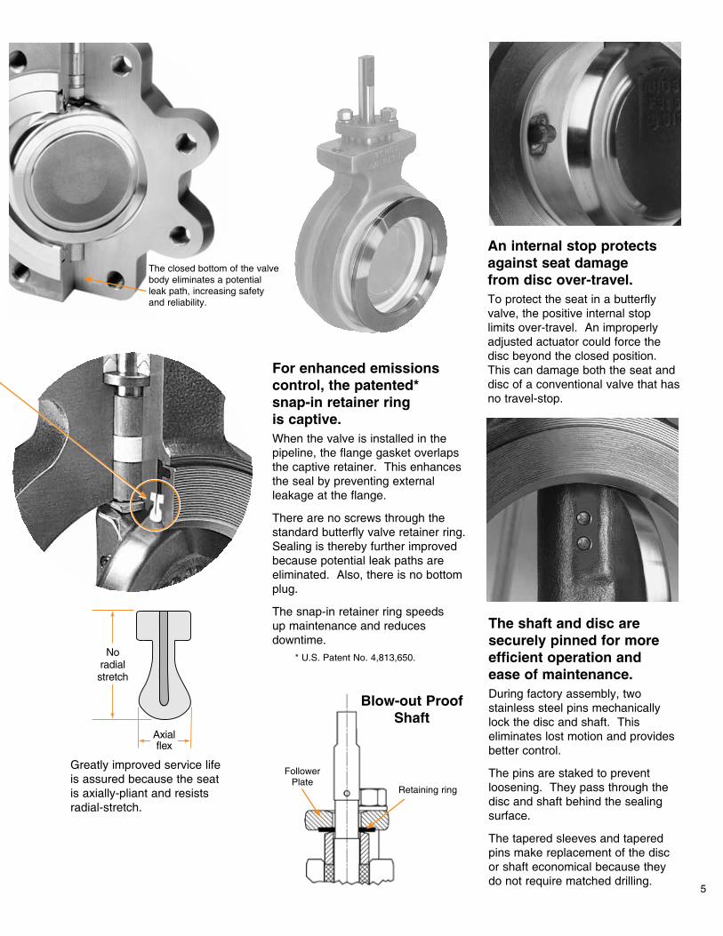
This is an extremely versatile valve. Choose from options and reconfigurations that meet specific application requirements.
In each case, the valve maintains the superior sealing character-istics and long-term economy of the standard Tufline design.
Vacuum service.Standard valves can be used to 25 mm mercury (Hg). Special cleaning, to minimize outgassing, is required for service to 1 x 10⁻⁶ mm of mercury.
Steam.Standard valves with reinforced PTFE (ST2) seats can be used in saturated steam applications up to 135 psia and 350° F.
XeniTh high-temp (ST20 & FT20) seats can be used for saturated and super-heated steam applica-tions up to 600° F.
Valves with CF8M stainless steel bodies are recommended for use in steam applications.
Oxygen and chlorine.Valves designated for oxygen or chlorine service are thoroughly cleaned and dried per Tufline oxygen and chlorine cleaning standards. After they are tested, valves are packaged and sealed in plastic containers.
NACE trim.Valves are available to meet the latest NACE specifications for materials used in sour environ-ments: NACE MR0175 / ISO 15156 and NACE MR0103-2003. This valve performs well in applications such as sour gas, sour oil, or other medias that can cause sulfide stress cracking or chloride stress cracking.
8
Fugitive emissions control.The Tufline emissions control valve is available with an auxiliary live-loaded packing option.
There are two full sets of packing separated by a lantern ring. Also available is an optional leak-off port (XP option).
Steam jacketed and internally steam traced (STJ Option).For processing solidifying or agglom-erating media, the Tufline STJ offers a patented 3-point heating system. The design includes an integral, full body steam jacket, a steam traced shaft, and steam tracing of the full circumference of the disc.
An adaptable design for specialized service.
XeniTh “ST” and “FT” HPBV’s are available in ASME Class150 and 300 design sizes 2” thru 24”. Lug and wafer designs in wide variety of Body and disc materials are available. Operating Temperatures up to 600°F.

Cryogenic.Both full and semi-cryogenic models are available. The bodies are stainless steel. The seats are a combination of stainless steel and Kel-F. Axially pliant sealing assures tight shutoff. See Xomox Bulletin 333767 for additional information.
Rail tank car.This bottom-mounted, bottom- operated Tufline valve is available with a steam jacketed body and a steam traced shaft and disc, as well as a stainless steel body
9
Body styles to meet your needs. This Tufline valve is available in three different body stylesand a variety of seat materials.
Wafer Style.Figure numbers
801, 803, and 806. The snap-in seat retainer ring provides a full 100%
gasket sealing width.
Lug Style with snap-in retainer.Uni-directional dead end service.
Figure numbers 811, 813, and 816. Designated for full pressure dead end service with the seat retainer ring located against the upstream flange. The snap-in seat retainer ring provides a full 100% gasket sealing width.
Lug Style with bolted retainer.
Bi-directional dead end service.
Figure numbers 821 and 823. Designated for full pressure dead end service with the seat retainer
ring located either against the upstream flange or exposed
downstream.
The screw-affixed seat retainer ring provides a minimum
65% gasket sealing width, as specified by API 609.

10
Dimensions Bare Stem P1
LugKWafer MCSize P2H LLug NWafer JA
5.10
6.41
2.44
3.80
1.33
.68
4.37
5.73
1.72
7.45
3.14
1.01
.11
23.50
27.50
13.13
18.76
9.75
6.00
20.99
25.25
10.74
32.25
16.00
8.63
4.62
21.25
25.00
11.75
17.00
8.50
6.00
18.75
22.75
9.50
29.50
14.25
7.50
4.75
29.18
36.56
16.06
21.25
12.61
10.00
25.68
31.12
13.75
41.06
19.25
11.51
8.74
1-8
11/8-8
3/4-10
7/8-9
3/4-10
5/8-11
1-8
11/8-8
3/4-10
11/4-8
7/8-9
5/8-11
5/8-11
3.50
5.75
3.25
3.50
3.25
3.25
3.50
3.50
3.25
5.75
3.50
3.25
3.25
16
20
8
12
5
3
14
18
6
24
10
4
2
5.45
7.03
2.64
4.22
1.39
.69
4.69
6.35
1.91
8.26
3.46
1.01
.49
14.43
18.15
7.45
11.05
4.81
3.13
12.59
16.30
5.77
21.59
9.27
4.02
2.19
16
20
8
12
8
4
12
16
8
20
12
8
4
29.18
36.56
16.56
22.53
13.16
10.33
26.11
31.12
14.28
41.06
20.28
12.10
8.76
15.00
18.81
7.62
11.38
4.81
2.90
13.13
16.88
5.77
22.63
9.56
3.83
1.94
18.50
23.07
10.88
15.23
7.62
5.38
16.25
21.00
8.62
27.25
12.98
6.75
4.00
13.12
15.50
7.12
10.00
5.38
4.00
11.62
14.12
6.00
17.75
9.00
4.88
3.38
4.00
5.00
2.50
3.19
2.25
1.88
3.62
4.50
2.25
6.06
2.81
2.12
1.75
EB
7.477.3521.5611/2-82432.0019.5021.5935.0027.255.7543.5643.567.0024
6.176.0417.9411/4-82427.0017.0018.1529.4923.005.7538.3838.386.1220
5.435.3016.1311/4-82424.7515.7516.3027.2521.005.7536.4336.435.7518
4.754.6214.3111/4-82022.5014.7514.4325.0018.505.7533.6933.695.2516
4.174.0512.5011/8-82020.2513.6212.5922.4916.255.7531.8731.874.5014
3.903.7211.3811/8-81617.7511.0011.0519.9815.273.5025.6825.683.6212
3.232.969.561-81615.259.569.2717.2512.973.5022.0423.043.2510
2.542.207.637/8-91213.008.257.4514.7610.873.5018.8918.622.878
1.801.795.773/4-101210.627.005.7712.128.673.2516.2416.032.316
1.09.973.833/4-1087.885.754.029.386.353.2513.6913.472.124
.77.642.903/4-1086.624.633.138.135.153.2511.6311.381.873
P2P1NMLKJHLugWaferCLugWaferASize EB
Class 300 / 740rP
6.10
3.36
4.98
2.76
4.65
3.24
4.65
2.76
18.00
11.06
17.00
9.31
17/8-8
11/4-8
15/8-8
11/4-8
24
20
24
16
33.00
19.25
28.50
17.00
21.00
13.12
18.12
11.88
18.96
11.05
17.75
9.27
39.50
21.75
31.75
19.50
30.75
16.25
23.00
15.07
7.50
5.75
7.50
5.75
50.50
30.93
46.37
28.19
50.50
30.93
46.37
28.19
9.13
5.50
8.50
4.62
24
12
20
10
4.61
2.06
4.28
1.94
15.25
7.44
15/8-8
11/8-8
20
12
25.75
13.75
16.75
9.50
15.68
7.45
28.75
15.99
21.00
10.62
5.75
3.50
38.75
21.69
38.75
21.69
7.25
4.00
18
8
3.75
1.72
3.53
1.58
13.80
5.77
11/2-8
1-8
20
12
23.75
11.50
15.75
8.12
13.70
5.77
26.71
13.49
26.71
8.50
5.75
3.25
37.25
19.06
37.25
19.06
7.00
3.06
16
6
3.53
1.43
3.20
1.03
12.12
3.83
13/8-8
7/8-9
20
8
20.75
8.50
14.25
6.12
12.59
4.02
23.75
10.25
16.25
6.62
5.75
3.25
34.00
14.81
34.00
14.81
6.12
2.50
14
4
.81.642.903/4-1086.625.253.138.125.313.2513.3113.312.253
P2P1NMLKJHLugWaferCLugWaferASize
Class 600 / 1480rP
Class 150 / 285rP
EB
For information on 30” - 48” Tufline High Performance Butterfly Valves, see Xomox Brochure 335251.
See page 13 for actuator mounting dimensions.
*Alignment hole allows clearance for specified bolt size.**Defines number of flange bolts required. Number of alignment holes varies by size and pressure class.
*
**

11
Dimensions - Manual ActuatorsFor soft (ST) seated valves. Valve weights are in pounds. Size A B C WT
(wafer)WT
(lug)2 1.75 6.69 14 15 193 1.88 7.31 14 18 234 2.12 8.19 14 27 335 2.25 8.69 17 32 396 2.25 9.31 17 38 458 2.50 10.44 17 56 69
Size A B C WT (wafer)
WT (lug)
3 1.88 7.94 14 20 284 2.12 9.06 17 30 426 2.31 10.31 17 41 60
Size HT HW X Z WT (wafer)
WT (lug)
2 6.75 8 1.83 5.00 13 163 7.38 8 1.83 5.00 16 204 8.25 8 1.83 5.00 25 305 8.75 8 1.83 5.00 29 356 9.38 8 1.83 5.00 35 418 10.50 8 2.36 6.00 55 6810 12.75 8 2.36 6.00 84 9712 13.94 12 3.00 9.75 123 15414 18.87 18 3.38 11.69 216 28116 20.37 24 3.38 14.37 277 38918 21.49 24 4.38 13.25 359 49620 25.37 24 4.38 13.25 526 61324 28.35 24 2.36 20.10 833 990
Size HT HW X Z WT (wafer)
WT (lug)
3 8.00 8 1.83 5.00 18 254 9.12 8 1.83 5.00 27 386 10.38 8 2.36 6.00 40 588 12.19 12 3.00 9.75 66 9810 13.75 18 4.38 11.69 154 20812 14.88 30 5.38 13.88 210 31414 23.49 30 5.38 15.44 344 55516 25.34 24 2.36 20.10 615 80718 25.59 24 2.10 20.10 729 94320 24.59 30 6.10 21.53 839 1,00424 27.05 24 7.13 23.92 1,275 1,844
Class 150 Lever
Class 300 Lever
Class 150 Gear
Class 300 Gear
Class 600 Gear
Size HT HW X Z WT (wafer)
WT (lug)
3 11.42 8 1.83 5.00 45 494 13.04 8 2.36 6.00 64 696 14.94 12 3.00 9.75 130 1388 16.84 18 4.38 11.69 300 308
10 21.75 30 5.38 15.44 500 51012 23.71 24 2.36 20.10 753 765

12
Dimensions - Manual ActuatorsFor fire tested (FT) and high temperature (HT) seated valves. Valve weights are in pounds.
Size A B C WT (wafer) WT (lug)2 1.75 6.69 14 15 193 1.88 7.31 14 18 234 2.12 8.19 14 27 335 2.25 8.69 17 32 396 2.25 9.31 17 38 45
Size A B C WT (wafer) WT (lug)3 1.88 7.94 14 20 284 2.12 9.06 17 30 42
Class 150 Lever
Class 300 Lever
Class 150 Gear
Class 300 Gear
Class 600 Gear
Size HT HW X Z WT (wafer) WT (lug)2 7.00 10 2.06 7.50 44 473 7.63 10 2.06 7.50 47 514 8.51 10 2.06 7.50 56 615 9.13 10 2.06 7.50 61 676 9.51 10 2.06 7.50 67 738 11.12 14 2.63 9.50 98 110
10 13.38 14 2.63 9.50 127 14012 14.62 18 3.53 11.13 191 22114 19.09 24 3.53 12.25 217 28216 20.59 30 4.84 15.88 312 42418 22.21 24 2.36 20.10 453 59020 25.37 18 2.10 18.76 618 70524 28.39 30 2.10 21.51 842 999
Size HT HW X Z WT (wafer) WT (lug)3 8.25 10 2.06 7.50 31 384 9.38 10 2.06 7.50 40 516 10.88 14 2.63 9.50 63 818 12.89 18 3.53 11.13 96 12810 14.00 24 3.53 12.25 142 19612 15.13 30 4.84 15.88 212 31614 24.22 30 2.36 21.51 426 63716 22.30 24 3.80 22.53 700 89218 23.30 24 3.80 24.11 823 1,05220 24.75 24 9.33 23.40 1,088 1,25324 27.25 30 9.33 24.90 1,457 2,026
Size HT HW X Z WT (wafer) WT (lug)
3 11.54 10 2.36 8.94 61 654 13.53 12 2.63 9.19 87 926 15.12 18 3.38 11.69 180 1888 16.87 24 4.38 13.25 300 31010 22.47 24 2.36 20.10 573 58312 23.71 24 2.36 20.10 753 765
13
6.251.532.440.811.252.441.0010
4.001.312.250.691.002.321.008
4.001.192.000.560.751.981.006
4.001.152.000.560.751.981.005
4.001.031.940.440.621.931.004
4.000.911.700.370.501.981.003
15.002.624.001.752.506.002.5024
15.002.193.621.502.005.502.0020
9.502.002.851.121.754.001.5018
9.501.832.851.121.754.001.5016
9.501.662.811.001.503.881.5014
6.251.762.621.001.503.451.5012
Thru1-82.001.0013.006.50
Thru1-82.001.0013.006.50
Thru5/8-111.500.758.004.00
Thru5/8-111.500.758.004.00
Thru5/8-111.500.758.004.00
0.751/2-131.500.755.002.50
0.751/2-131.500.755.002.50
0.751/2-13--3.121.56
0.751/2-13--3.121.56
0.751/2-13--3.121.56
AJAH
0.751/2-13
AFAE
--
ADAC
3.12
AB
1.56
0.751/2-13--3.121.56
ARAPANAMALAKValve Size
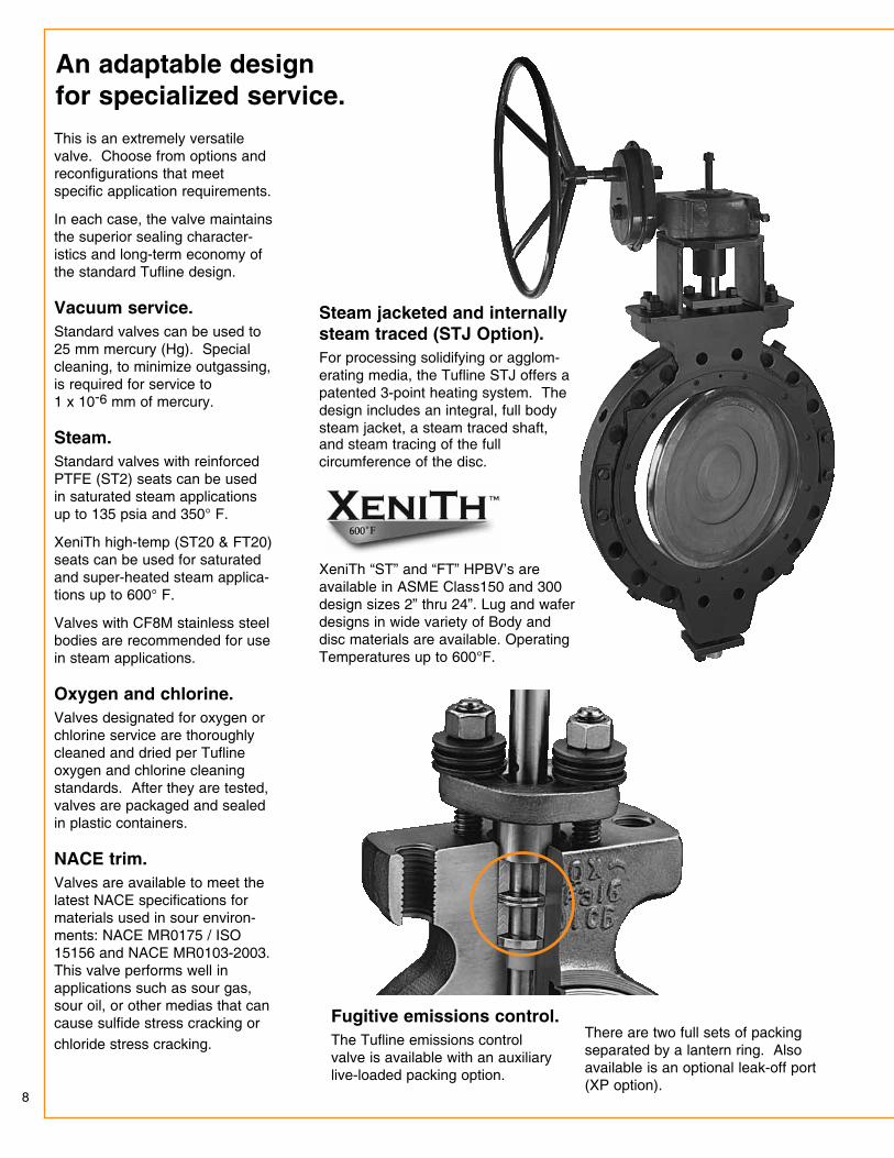
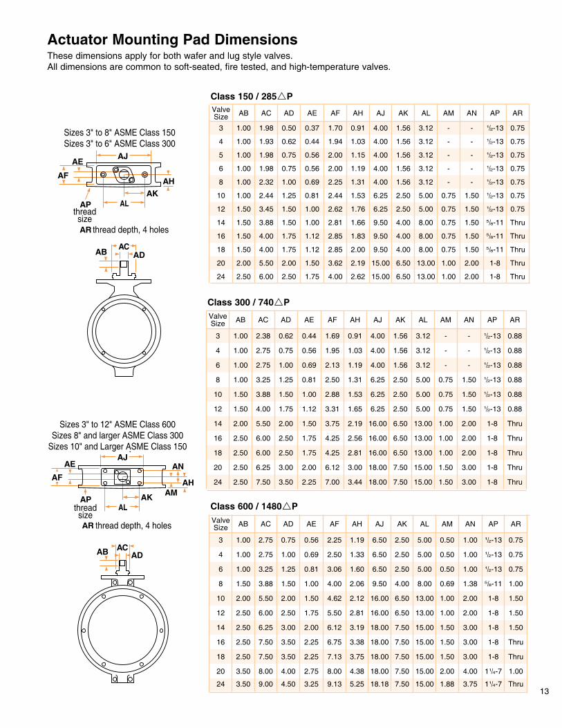
Actuator Mounting Pad DimensionsThese dimensions apply for both wafer and lug style valves. All dimensions are common to soft-seated, fire tested, and high-temperature valves.
Class 150 / 285rP
Class 300 / 740rP
Class 600 / 1480rP
Sizes 3" to 8" ASME Class 150Sizes 3" to 6" ASME Class 300
Sizes 3" to 12" ASME Class 600Sizes 8" and larger ASME Class 300
Sizes 10" and Larger ASME Class 150
threadsize
threadsize
thread depth, 4 holesthread depth, 4 holes
Sizes 3" to 8" ASME Class 150Sizes 3" to 6" ASME Class 300
Sizes 3" to 12" ASME Class 600Sizes 8" and larger ASME Class 300
Sizes 10" and Larger ASME Class 150
threadsize
threadsize
thread depth, 4 holesthread depth, 4 holes
6.251.653.311.121.754.001.5012
6.251.532.881.001.503.881.5010
6.251.312.500.811.253.251.008
4.001.192.130.691.002.751.006
4.001.031.950.560.752.751.004
4.000.911.690.440.622.381.003
18.003.447.002.253.507.502.5024
18.003.006.122.003.006.252.5020
16.002.814.251.752.506.002.5018
16.002.564.251.752.506.002.5016
16.002.193.751.502.005.502.0014
Thru1-83.001.5015.007.50
Thru1-83.001.5015.007.50
Thru1-82.001.0013.006.50
Thru1-82.001.0013.006.50
Thru1-82.001.0013.006.50
0.881/2-131.500.755.002.50
0.881/2-131.500.755.002.50
0.881/2-131.500.755.002.50
0.881/2-13--3.121.56
AJAH
0.881/2-13
AFAE
--
ADAC
3.12
AB
1.56
0.881/2-13--3.121.56
ARAPANAMALAKValve Size
18.18
18.00
18.00
18.00
18.00
16.00
5.25
4.38
3.38
3.75
3.19
2.81
9.13
8.00
6.75
7.13
6.12
5.50
3.25
2.75
2.25
2.25
2.00
1.75
4.50
4.00
3.50
3.50
3.00
2.50
9.00
8.00
7.50
7.50
6.25
6.00
3.50
3.50
2.50
2.50
2.50
2.50
24
20
16
18
14
12
16.002.124.621.502.005.502.0010
9.502.064.001.001.503.881.508
6.501.603.060.811.253.251.006
6.501.332.500.691.002.751.004
6.501.192.250.560.752.751.003
Thru
1.00
Thru
Thru
1.50
1.50
11/4-7
11/4-7
1-8
1-8
1-8
1-8
3.75
4.00
3.00
3.00
3.00
2.00
1.88
2.00
1.50
1.50
1.50
1.00
15.00
15.00
15.00
15.00
15.00
13.00
7.50
7.50
7.50
7.50
7.50
6.50
1.501-82.001.0013.006.50
1.005/8-111.380.698.004.00
0.751/2-131.000.505.002.50
AJAH
0.751/2-13
AFAE
1.000.50
ADAC
5.00
AB
2.50
0.751/2-131.000.505.002.50
ARAPANAMALAKValve Size

Typical ST seat specification.
1.0 ScopeThis specification covers the design and testing of high pressure offset seat butterfly valves.
2.0 Applicable Standards The following standards shall apply: ASME B16.5: Pipe Flanges and Flanged Fittings (24” size and smaller) ASME B16.34: Valves - Flanged and Buttwelding End MSS SP-25: Standard Marking System for Valves, Fittings, Flanges, and Unions MSS SP-61: Pressure Testing of Steel Valves MSS SP-68: High Pressure - Offset Seat Butterfly Valves API 598: Valve Inspection and Testing API 609: Butterfly Valves, Lug-Type and Wafer-Type PED 97/23 EG: Pressure Equipment Directive Annex II, Module H
3.0 Design Requirements3.1 Valves shall be High Performance Butterfly with offset seat and eccentric shaft. They shall be capable of sealing against full differential pressure in either flow direction. 3.2 Valve seat shall be both self and pressure energized with an inert, fiberglass core. The self-energizing Fiberglass member shall be isolated from the line media. 3.3 Valves shall have retained top and bottom low-friction bearings. 3.4 Shaft design shall be single or dual piece. 3.5 Seat retainer rings must be recessed in the body so the flange gasket prevents any potential external leakage. 3.6 Valves shall have internal over-travel stops to prevent the disc from rotating through the seats. 3.7 Valves shall be Tufline or approved equal.
4.0 Materials of Construction 4.1 Valves shall be constructed using new materials and components. 4.2 Carbon steel valves shall be constructed from the following materials: 4.2.1 Body - ASTM A216 Grade WCB 4.2.2 Disc - ASTM A351 Grade CF-8M 4.3 Stainless steel valves shall be constructed from the following materials: 4.3.1 Body - ASTM A351 Grade CF-8M 4.3.2 Disc - ASTM A351 Grade CF-8M 4.4 Shafts shall be ASTM A564 Type 630, H 1075 (17-4PH) SS or 316 SS.
5.0 Inspection and Testing 5.1 Valves shall be hydrostatically shell tested per ASME B16.34 and MSS SP-61. 5.2 Valves shall be seat tested per ASME B16.34 and MSS SP-61. No leakage is permitted for resilient seated valves. 5.3 API 598 testing is available on request.
Sample Figure Number: 6” 801-267-TT-ST2-L
Typical FT seat specification.
1.0 Scope This specification covers the design and testing of high pressure offset seat butterfly valves.
2.0 Applicable Standards The following standards shall apply: ASME B16.5: Pipe Flanges and Flanged Fittings (24” size and smaller) ASME B16.34: Valves - Flanged and Buttwelding End MSS SP-25: Standard Marking System for Valves, Fittings, Flanges, and Unions MSS SP-61: Pressure Testing of Steel Valves MSS SP-68: High Pressure - Offset Seat Butterfly Valves API 598: Valve Inspection and Testing API 607: Fire Test for Soft-Seated Quarter Turn Valves API 609: Butterfly Valves, Lug-Type and Wafer-Type PED 97/23 EG: Pressure Equipment Directive Annex II, Module H
3.0 Design Requirements 3.1 Valves shall be High Performance Butterfly with offset seat and eccentric shaft. They shall be capable of sealing against full differential pressure in either flow direction. 3.2 Valve seat shall be both self and pressure energized with two (2) metal sealing points and one (1) PTFE or similar material insert in contact with the disc at all times. 3.3 Valves shall have retained top and bottom low-friction bearings. 3.4 Shaft design shall be single or dual piece. 3.5 Seat retainer rings must be recessed in the body so the flange gasket prevents any potential external leakage. 3.6 Valves shall have internal over-travel stops to prevent the disc from rotating through the seats. 3.7 Valves shall be Tufline or approved equal.
4.0 Materials of Construction 4.1 Valves shall be constructed using new materials and components. 4.2 Carbon steel valves shall be constructed from the following materials: 4.2.1 Body - ASTM A216 Grade WCB 4.2.2 Disc - ASTM A351 Grade CF-8M 4.3 Stainless steel valves shall be constructed from the following materials: 4.3.1 Body - ASTM A351 Grade CF-8M 4.3.2 Disc - ASTM A351 Grade CF-8M 4.4 Shafts shall be ASTM A564 Type 630, H 1075 or H 1150-M (17-4PH) SS.
5.0 Inspection and Testing 5.1 Valves shall be hydrostatically shell tested per ASME B16.34 and MSS SP-61. 5.2 Valves shall be seat tested per ASME B16.34 and MSS SP-61. No leakage is permitted for resilient seated valves. 5.3 API 598 testing is available on request. 5.4 Fire tested valves shall be qualified to API 607, 4TH Edition fire test standard.
Sample Figure Number: 6” 801-267-SG-FT1-G
Typical HT seat specification.
1.0 Scope This specification covers the design and testing of high pressure offset seat butterfly valves.
2.0 Applicable Standards The following standards shall apply: ASME B16.5: Pipe Flanges and Flanged Fittings (24” size and smaller) ASME B16.34: Valves - Flanged and Buttwelding End ASME/FCI 70-2: Control Valve Seat Leakage MSS SP-25: Standard Marking System for Valves, Fittings, Flanges, and Unions MSS SP-68: High Pressure - Offset Seat Butterfly Valves API 609: Butterfly Valves, Lug-Type and Wafer-Type PED 97/23 EG: Pressure Equipment Directive Annex II, Module H
3.0 Design Requirements 3.1 Valves shall be High Performance Butterfly with offset seat and eccentric shaft. They shall be capable of providing 10% of Class IV shutoff in either flow direction. 3.2 Valve seat shall be both self and pressure energized with two (2) metal sealing points in contact with the disc at all times. 3.3 Valves shall have retained top and bottom low-friction bearings. 3.4 Shaft design shall be single or dual piece. 3.5 Seat retainer rings must be recessed in the body so the flange gasket prevents any potential external leakage. 3.6 Valves shall have internal over-travel stops to prevent the disc from rotating through the seats. 3.7 Valves shall be Tufline or approved equal.
4.0 Materials of Construction 4.1 Valves shall be constructed using new materials and components. 4.2 Carbon steel valves shall be constructed from the following materials: 4.2.1 Body - ASTM A216 Grade WCB 4.2.2 Disc - ASTM A351 Grade CF-8M 4.3 Stainless steel valves shall be constructed from the following materials: 4.3.1 Body - ASTM A351 Grade CF-8M 4.3.2 Disc - ASTM A351 Grade CF-8M 4.4 Shafts shall be ASTM A564 Type 630, H 1075 or H 1150-M (17-4PH) SS.
5.0 Inspection and Testing 5.1 Valves shall be hydrostatically shell tested per ASME B16.34 and MSS SP-61. 5.2 Valves shall be seat tested per ASME/FCI 70-2 to 10% of Class IV.
Sample Figure Number: 6” 801-267-SG-HT1-G
Tufline High Performance Butterfly Valve Specifications
14
15
21363175694046 91881348 132712662 647350424
15250125422888 6559962 94731900 462136020
12328101382335 5302778 76581536 373529118
949078051797 4082599 58951182 287522416
730360061383 3141461 4537910 221317214
529543541003 2277334 3289660 160412512
36823028697 1584232 2287459 11168710
23161905439 996146 1439289 702558
13501110255 58185 839166 409326
816671154 35151 507102 247195
51742598 22233 32164 157124
29624456 12719 18437 9073
15212529 6510 9419 464
90o80o40o 60o20o 70o30o 50o10o
2
Valve Size
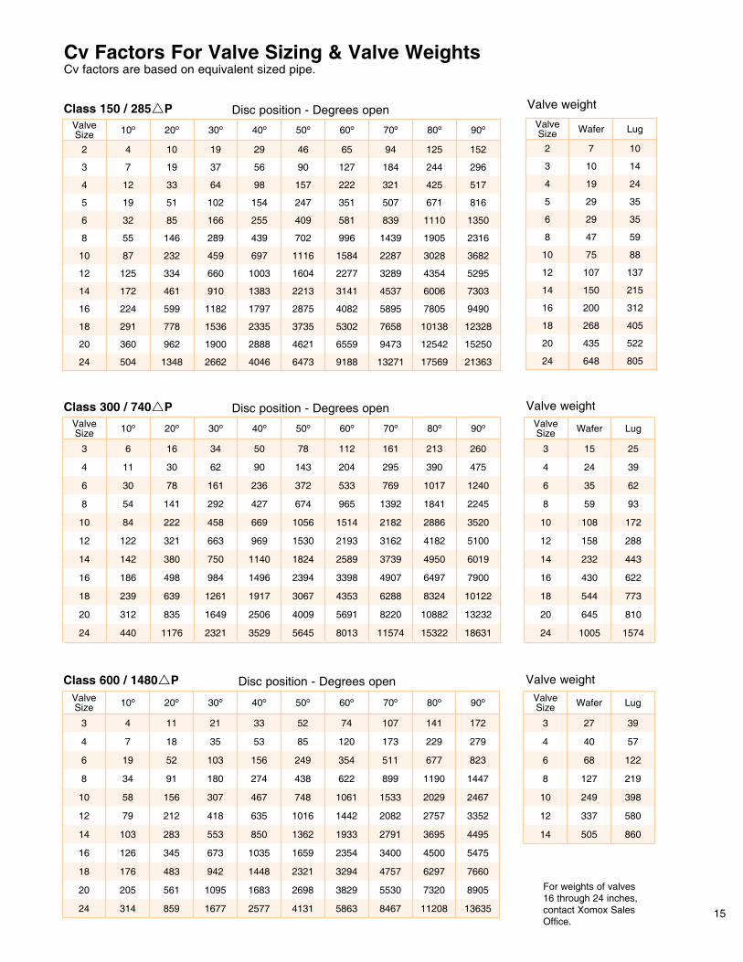
Class 150 / 285rP Disc position - Degrees open Valve weight
Valve weight
Valve weight
Cv Factors For Valve Sizing & Valve Weights Cv factors are based on equivalent sized pipe.
117644024
83531220
63923918
49818616
380142
18631
13232
10122
7900
6019
5100
3520
2245
14
321122
1240
475
260
90o
80135645
56914009
12
22284
43533067
33982394
25891824
21931530
10
14154
15141056
965674
533372
204143
11278
8
7830
1532211574
108828220
6
60o50o
83246288
64974907
49503739
41823162
28862182
3011
18411392
1017769
390295
213161
4
166
80o70o
35292321
25061649
3
20o10o
19171261
1496984
1140750
969663
669458
427292
236161
9062
5034
40o30oValve Size
859
212
314
79
24
12
561
156
205
58
20
10
483
91
176
34
18
8
345
52
126
19
16
6
283
18
103
7
14
4
114
13635
3352
8905
2467
7660
1447
5475
823
4495
279
1723
90o
5863
1442
4131
1016
3829
1061
2698
748
3294
622
2321
438
2354
354
1659
249
1933
120
1362
85
7452
11208
2757
8467
2082
7320
2029
5530
1533
6297
1190
4757
899
60o50o
4500
677
3400
511
3695
229
2791
173
141107
80o70o
2577
635
1677
418
1683
467
1095
307
1448
274
942
180
20o10o
1035
156
673
103
850
53
553
35
3321
40o30oValve Size
Class 300 / 740rP Disc position - Degrees open
Class 600 / 1480rP Disc position - Degrees open
80564824
52243520
40526818
31220016
21515014
13710712
887510
59478
35296
35295
24194
14103
107
LugWafer
2
Valve Size
1574100524
81064520
77354418
62243016
44323214
28815812
17210810
93598
62356
39244
25153
LugWaferValve Size
86050514
58033712
39824910
2191278
122686
57404
39273
LugWaferValve Size
For weights of valves 16 through 24 inches, contact Xomox Sales Office.

16
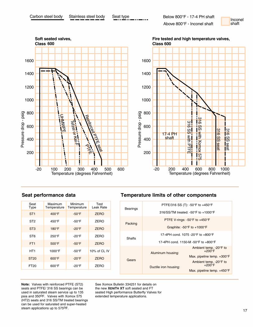
Pressure/Temperature Ratings For Various Seat MaterialsBody pressure/temperature ratings are in accordance with ANSI B16.34
17
Seat performance data Temperature limits of other components
ZERO
10% of CL IV
-20°F
-50°F
600°F
1000°F
FT20
HT1
ZERO
ZERO
-20°F
-50°F
600°F
500°F
ST20
FT1
ZERO-20°F250°FST6
ZERO-20°F180°FST3
ZERO-50°F450°FST2
ZERO-50°F400°FST1
Test Leak Rate
Minimum Temperature
Maximum Temperature
Seat Type
Max. pipeline temp. +450°F
Ambient temp. -20°F to +200°FDuctile iron housing:
Max. pipeline temp. +300°F
Ambient temp. -20°F to +200°FAluminum housing:
Gears
17-4PH cond. 1150-M -50°F to +800°F
17-4PH cond. 1075 -20°F to +800°FShafts
Graphite: -50°F to +1000°F
PTFE V-rings: -50°F to +450°FPacking
316/SS/TM treated: -50°F to +1000°F
PTFE/316 SS (T): -50°F to +450°FBearings
Note: Valves with reinforced PTFE (ST2) seats and PTFE/ 316 SS bearings can be used in saturated steam service up to 135 psia and 350oF. Valves with Xomox 575 (HT2) seats and 316 SS/TM treated bearings can be used for saturated and super-heated steam applications up to 575oF.
See Xomox Bulletin 334251 for details on the new XENITH XT soft seated and FT seated High performance Butterfly Valves for extended temperature applications.
18
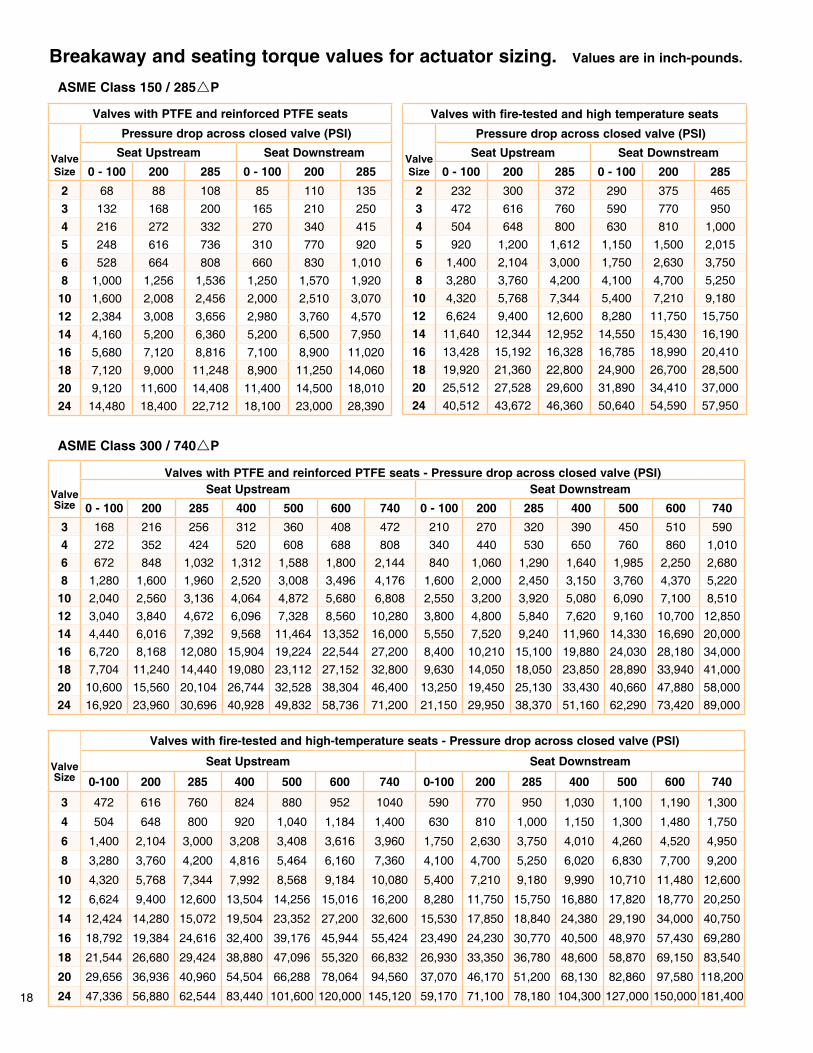
Breakaway and seating torque values for actuator sizing. Values are in inch-pounds.
Valves with PTFE and reinforced PTFE seats
Valve Size
Pressure drop across closed valve (PSI)Seat Upstream Seat Downstream
0 - 100 200 285 0 - 100 200 2852 68 88 108 85 110 1353 132 168 200 165 210 2504 216 272 332 270 340 4155 248 616 736 310 770 9206 528 664 808 660 830 1,0108 1,000 1,256 1,536 1,250 1,570 1,920
10 1,600 2,008 2,456 2,000 2,510 3,07012 2,384 3,008 3,656 2,980 3,760 4,57014 4,160 5,200 6,360 5,200 6,500 7,95016 5,680 7,120 8,816 7,100 8,900 11,02018 7,120 9,000 11,248 8,900 11,250 14,06020 9,120 11,600 14,408 11,400 14,500 18,01024 14,480 18,400 22,712 18,100 23,000 28,390
Valves with fire-tested and high temperature seats
Valve Size
Pressure drop across closed valve (PSI)Seat Upstream Seat Downstream
0 - 100 200 285 0 - 100 200 2852 232 300 372 290 375 4653 472 616 760 590 770 9504 504 648 800 630 810 1,0005 920 1,200 1,612 1,150 1,500 2,0156 1,400 2,104 3,000 1,750 2,630 3,7508 3,280 3,760 4,200 4,100 4,700 5,250
10 4,320 5,768 7,344 5,400 7,210 9,18012 6,624 9,400 12,600 8,280 11,750 15,75014 11,640 12,344 12,952 14,550 15,430 16,19016 13,428 15,192 16,328 16,785 18,990 20,41018 19,920 21,360 22,800 24,900 26,700 28,50020 25,512 27,528 29,600 31,890 34,410 37,00024 40,512 43,672 46,360 50,640 54,590 57,950
Valve Size
Valves with PTFE and reinforced PTFE seats - Pressure drop across closed valve (PSI)Seat Upstream Seat Downstream
0 - 100 200 285 400 500 600 740 0 - 100 200 285 400 500 600 7403 168 216 256 312 360 408 472 210 270 320 390 450 510 5904 272 352 424 520 608 688 808 340 440 530 650 760 860 1,0106 672 848 1,032 1,312 1,588 1,800 2,144 840 1,060 1,290 1,640 1,985 2,250 2,6808 1,280 1,600 1,960 2,520 3,008 3,496 4,176 1,600 2,000 2,450 3,150 3,760 4,370 5,220
10 2,040 2,560 3,136 4,064 4,872 5,680 6,808 2,550 3,200 3,920 5,080 6,090 7,100 8,51012 3,040 3,840 4,672 6,096 7,328 8,560 10,280 3,800 4,800 5,840 7,620 9,160 10,700 12,85014 4,440 6,016 7,392 9,568 11,464 13,352 16,000 5,550 7,520 9,240 11,960 14,330 16,690 20,00016 6,720 8,168 12,080 15,904 19,224 22,544 27,200 8,400 10,210 15,100 19,880 24,030 28,180 34,00018 7,704 11,240 14,440 19,080 23,112 27,152 32,800 9,630 14,050 18,050 23,850 28,890 33,940 41,00020 10,600 15,560 20,104 26,744 32,528 38,304 46,400 13,250 19,450 25,130 33,430 40,660 47,880 58,00024 16,920 23,960 30,696 40,928 49,832 58,736 71,200 21,150 29,950 38,370 51,160 62,290 73,420 89,000
Valve Size
Valves with fire-tested and high-temperature seats - Pressure drop across closed valve (PSI)
Seat Upstream Seat Downstream
0-100 200 285 400 500 600 740 0-100 200 285 400 500 600 740
3 472 616 760 824 880 952 1040 590 770 950 1,030 1,100 1,190 1,300
4 504 648 800 920 1,040 1,184 1,400 630 810 1,000 1,150 1,300 1,480 1,750
6 1,400 2,104 3,000 3,208 3,408 3,616 3,960 1,750 2,630 3,750 4,010 4,260 4,520 4,950
8 3,280 3,760 4,200 4,816 5,464 6,160 7,360 4,100 4,700 5,250 6,020 6,830 7,700 9,200
10 4,320 5,768 7,344 7,992 8,568 9,184 10,080 5,400 7,210 9,180 9,990 10,710 11,480 12,600
12 6,624 9,400 12,600 13,504 14,256 15,016 16,200 8,280 11,750 15,750 16,880 17,820 18,770 20,250
14 12,424 14,280 15,072 19,504 23,352 27,200 32,600 15,530 17,850 18,840 24,380 29,190 34,000 40,750
16 18,792 19,384 24,616 32,400 39,176 45,944 55,424 23,490 24,230 30,770 40,500 48,970 57,430 69,280
18 21,544 26,680 29,424 38,880 47,096 55,320 66,832 26,930 33,350 36,780 48,600 58,870 69,150 83,540
20 29,656 36,936 40,960 54,504 66,288 78,064 94,560 37,070 46,170 51,200 68,130 82,860 97,580 118,200
24 47,336 56,880 62,544 83,440 101,600 120,000 145,120 59,170 71,100 78,180 104,300 127,000 150,000 181,400
ASME Class 300 / 740rP
ASME Class 150 / 285rP

19
Breakaway and seating torque values for actuator sizing. Values are in inch-pounds.
ASME Class 600 / 1,480rP
Valve Size
Valves with PTFE and reinforced PTFE seats - Pressure drop across closed valve (PSI)Seat Upstream Seat Downstream
0-200 400 600 740 1,000 1,200 1,480 0-200 400 600 740 1,000 1,200 1,4803 320 360 456 528 688 824 992 400 450 570 660 860 1,030 1,2404 496 648 824 968 1,264 1,480 1,816 620 810 1,030 1,210 1,580 1,850 2,2706 1,048 1,368 1,848 2,232 2,728 3,208 3,936 1,310 1,710 2,310 2,790 3,410 4,010 4,9208 1,760 2,648 3,616 4,384 5,280 6,512 7,672 2,200 3,310 4,520 5,480 6,600 8,140 9,590
10 5,464 6,768 8,120 9,456 12,064 14,360 16,888 6,830 8,460 10,150 11,820 15,080 17,950 21,11012 6,784 9,320 12,424 15,096 19,280 22,760 27,016 8,480 11,650 15,530 18,870 24,100 28,450 33,77014 10,632 14,640 16,616 23,496 30,008 34,160 38,000 13,290 18,300 20,770 29,370 37,510 42,700 47,50016 18,072 24,888 28,248 39,944 51,016 58,072 64,600 22,590 31,110 35,310 49,930 63,770 72,590 80,75018 21,800 30,024 34,072 48,176 61,532 70,048 77,920 27,250 37,530 42,590 60,220 76,915 87,560 97,40020 30,840 42,472 48,200 68,160 87,040 99,120 110,240 38,550 53,090 60,250 85,200 108,800 123,900 137,80024 47,320 65,160 73,952 104,560 133,520 152,000 169,120 59,150 81,450 92,440 130,700 166,900 190,000 211,400
Valve Size
Valves with fire-tested and high temperature seats - Pressure drop across closed valve (PSI)
Seat Upstream Seat Downstream
0-200 400 600 740 1,000 1,200 1,480 0 - 200 400 600 740 1,000 1,200 1,480
3 672 872 968 1,136 1,264 1,520 1,816 840 1,090 1,210 1,420 1,580 1,900 2,270
4 752 1,032 1,288 1,536 1,824 2,136 2,624 940 1,290 1,610 1,920 2,280 2,670 3,280
6 2,168 3,344 3,720 4,096 4,288 4,944 6,064 2,710 4,180 4,650 5,120 5,360 6,180 7,580
8 4,136 5,072 6,376 7,728 9,304 11,480 13,520 5,170 6,340 7,970 9,660 11,630 14,350 16,900
10 10,240 11,096 13,120 14,000 16,080 19,120 22,480 12,800 13,870 16,400 17,500 20,100 23,900 28,100
12 13,840 17,200 18,160 19,840 25,320 29,888 35,480 17,300 21,500 22,700 24,800 31,650 37,360 44,350
14 18,440 24,520 28,056 33,880 39,408 44,856 49,904 23,050 30,650 35,070 42,350 49,260 56,070 62,380
16 31,360 41,680 47,680 57,600 66,960 76,240 84,800 39,200 52,100 59,600 72,000 83,700 95,300 106,000
18 37,840 50,280 57,520 69,440 80,800 92,000 102,320 47,300 62,850 71,900 86,800 101,000 115,000 127,900
20 53,520 71,120 81,360 98,240 114,400 130,160 144,800 66,900 88,900 101,700 122,800 143,000 162,700 181,000
24 82,080 109,120 124,880 150,800 175,360 199,600 222,080 102,600 136,400 156,100 188,500 219,200 249,500 277,600
The sizing of an actuator is dependent on several variables: pressure drop, seat, packing, and bearing materials, available air pressure, closing speed, and media.
The following torque values are based on the assumption of clean, clear fluid, at ambient temperature, and standard bearing and packing materials.
Notes 1. For valve seats made of UHMWPE (ST3), add 20% to the torque values listed for PTFE and reinforced PTFE seats.
2. For valve seats made of 316 SS / Xomox 575 (HT2), add 30% to the torque values listed for fire-tested and high temperature seats.
3. Consult factory for rP limitations on shaft materials other than 17-4PH SS.

20
Valve components - General second generation exploded view diagram.Components and quantities may vary based on valve size, pressure class, or body style.

Standard Materials Of Construction.
Soft seated valves High temperature & fire tested valvesPart Description Carbon/316 316/316
Body 1Cast: A216 Gr. WCB 4
Forging: A105 4
Plate: A515 Gr. 70 2, 4A351 Gr. CF8M
Disc 1Cast: A351 Gr. CF8M
Forging: A182 Gr. F316
Cast: A351 Gr. CF8M Forging: A182
Gr. F316
Retainer 1A515 Gr. 70 carbon steel
2, 4 A240 Type 316 stainless steel
Follower A216 Gr. WCB 4 or C1018 carbon
A351 Gr. CF8M or 316 stainless steel
Follower stud A193 B7 A193 B8
Follower screw 3, 8
Packing 1
Plug seal 1, 3, 8
Shaft 1
High collar lockwasher 3, 8
Membrane
Hollow pin 1
Roll pin 3, 8
Retainer screws 1
Plug/sealing cap 1, 3, 8
Bearing 1
Stop ring 3, 8
Seat 1
Gland
Taper pin 1
Packing ring 1
Disc spacer 1
Lockwasher
Follower nut
C1035 carbon steel 6
PTFE
PTFE
17-4 PH stainless steel
Carbon steel 6
Fiberglass/PTFE
316 stainless steel
Carbon steel 6
A193 B8MA Class 1
316 stainless steelC 1020 carbon steel 6
Fiberglass/PTFE with 316 stainless steel backing
C4130 carbon steel 4
Reinforced PTFE
316 stainless steel
Nitronic 50 or 316 stainless steel
316 stainless steel
A747 Grade CB-7CU or A351 Gr. CF8M 5
Carbon steel 7
A194 2H
302 stainless steel
A194 Gr.8
C1035 carbon steel 6Follower screw 3, 8
Carbon steel 6Roll pin 3, 8
Carbon steel 6High collar lockwasher 3, 8
C4130 carbon steel 4Stop ring 3, 8
GrafoilPlug seal 1, 3, 8
316 stainless steelC 1020 carbon steel 6Plug/sealing cap 1, 3, 8
316 stainless steelGland
316 stainless steelPacking ring 1
Reinforced graphitePacking 1
A193 B8MA Class 1Retainer screws 1
Reinforced graphiteSeat gasket 1
316 stainless steel with PTFE, 316 stainless steelSeat 1
17-4 PH stainless steelShaft 1
316 stainless steel 9Bearing 1
316 stainless steelHollow pin 1
Nitronic 50 or 316 stainless steelTaper pin 1
A747 Grade CB-7CU or A351 Gr. CF8M 5Disc spacer 1
302 stainless steelCarbon steel 7Lockwasher
A194 Gr.8A194 2HFollower nut
A193 B8A193 B7Follower stud
A351 Gr. CF8M or 316 stainless steel
A216 Gr. WCB 4
or C1018 carbonFollower
A240 Type 316 stainless steel
A515 Gr. 70 carbon steel 2, 4 Retainer 1
Cast: A351 Gr. CF8M 9 Forging: A182 Gr. F316 9
Cast: A351 Gr. CF8M 9
Forging: A182 Gr. F316 9Disc 1
A351 Gr. CF8MCast: A216 Gr. WCB 4
Forging: A105 4
Plate: A515 Gr. 70 2, 4Body 1
316/316Carbon/316Part Description
1. Wetted parts. 2. A516 Gr. 70 available on request. 3. For valves with 2-inch diameter shaft or larger. 4. Black oxide coated. 5. Chrome plating. 6. Cadmium plating. 7. Zinc plating. 8. 14-inch to 24-inch Class 150/300 and 3-inch to 24-inch Class 600 valves only. 9. Electroless NiCu plating.
21

22
General Notes:
1 - API 609 face to face dimensions are standard. Any other face to face requirements must be specified.
2 - Aluminum gear maximum 300°F line temperature. Use DI above 300°F.
3 - Single set. For double set with leak-off consult factory. Not to be
used when lever actuator is required. 4 - 350°F maximum in steam service.
5 - Consult factory for P limitations on shaft materials other than 17-4 PH.
6 - Double length (XP) extended packing (TFE) with live-loading bevel washers and monitoring port.
For information on 30” - 48” Tufline High Performance Butterfly Valves, see Xomox Brochure 335251.
For sizes and materials not shown, consult factory.
Below is an example of the Tufline High Performance Butterfly Valve ordering code:
For bi-directional dead end service, you must use body type 821, or 823 valves. These valves have retainers specially designed for such service. Use of body type 811, 813, or 816 valves in such service will result in massive leakage.

23
CRANE ChemPharma, Xomox & Matryx® Actuators.Tufline Valves are available as part of a complete valve package.
Actuators are available in three models: • Double acting vane • Rack & pinion spring return • Electric
Tufline automated valve packages assure you of single-source responsi-bility for flow control equipment.
With Tufline valves, Matryx and Xomox actuators, Xomox control accessories, and Tufline problem solving expertise, you are assured of valve packages that will provide optimum performance in your application.
Solid performance data means processors can size actuators with more of a confidence factor and less of a “fudge-factor”. Initial cost, repair costs, replacement costs, and costly downtime can all be reduced.
Rack and pinion actuators are available in both double-acting and spring-return models with both 90° and 180° rotation.
CRANE ChemPharma, Xomox Automation & Service Centers.Strategically located Xomox Automation & Service Centers provide a variety of services. These range from standard repair to major modification and accessory packaging.

CRANE ChemPharma Flow Solutions™
brands you trust.
CRANE ChemPharma Flow Solutions Include: Pipe - Valves - Fitting - Actuators - Pumps
Crane Co., and its subsidiaries cannot accept responsibility for possible errors in catalogues, brochures, other printed materials, and web-site information. Crane Co. reserves the right to alter its products without notice, including products already on order provided that such alteration can be made without changes being necessary in specifications already agreed. All trademarks in this material are property of the Crane Co. or its subsidiaries. The Crane and Crane brands logotype (Xomox®, Saunders®, Resistoflex®, Resistopure™, PSI®, DEPA®, ELRO®, REVO®) are registered trademarks of Crane Co. All rights reserved.
© 2010 CRANE ChemPharma Flow Solutions, www.cranechempharma.com
XOMOX International GmbH & Co.
Von-Behring-Straße 15,
D-88131 Lindau/Bodensee
Tel.: (49) 8382-702-0
Fax. (49) 8382-702-144
XOMOX Headquarters
4444 Cooper Road,
Cincinnati, OH 45242, U.S.A.
Tel.: (513) 745-6000
Fax: (513) 745-6086
CP-
XOM
OX
-HPB
V-B
U-E
N-C
I-4/
10-P
N32
9389
www.flowoffluids.com