A comparative study of non-thermal plasma assisted reforming technologies.pdf
Upload
jeremy-sohCategory
view
483download
20
FUEL
ELSEVIER Fuel Processing Technology 42 (1995) 85-107
PROCESSING TECHNOLOGY
Tubular reforming and autothermal reforming of natural gas - an overview of available processes
Ib Dybkjax* Haldor Topwe A/S, Nymallevej 55, DK-2800 Lyngby, Denmark
Received 7 February 1994; accepted in revised form 12 July 1994
Abstract
Tubular reforming and autothermal or secondary reforming of natural gas are the most important process steps in the production of synthesis gas. The paper reviews the state-of-the- art of the technologies with emphasis on new developments in equipment design, especially relating to the tubular reformer furnace and to the burner for the autothermal or secondary reformer. The chemical reactions are briefly described, and the various steam reforming processes - tubular, fired reforming, heat exchange reforming, and adiabatic pre-reforming - are reviewed. The difference between autothermal and secondary reforming and new develop- ments in these process technologies are highlighted.
1. Introduction
Natural gas is the most important raw material for, production of ammonia, methanol, hydrogen, carbon monoxide, and many other important products. In almost all cases it is converted catalytically by reaction with steam and/or oxygen- containing gases, i.e. air, enriched air, or oxygen. The related technologies, i.e. the various versions and combinations of steam reforming and autothermal or secondary reforming, are thus key technologies in the petrochemical and fertilizer industries today.
The technologies have been known and applied in the industry for more than 50 years and must today be considered quite mature. However, important new develop- ments are constantly being made, both in equipment design and in the related catalysts. The purpose of the present paper is to review the state-of-the-art and to describe recent developments for tubular reforming and autothermal and secondary reforming with emphasis on process concepts and design of critical items.
* Tel.: + 45 45 27 29 99. Fax: + 45 45 27 20 00.
0378-3820/95/%09.50 0 1995 Elsevier Science B.V. All rights reserved SSDI 0378-3820(94)00099-9
86 I. DybkjmlFuel Processing Technology 42 (1995) 85-107
The conversion of natural gas may be done by several different processes or combinations of processes. The most important options are: (i) tubular, fired reform- ing; (ii) heat exchange reforming; (iii) adiabatic pre-reforming; (iv) autothermal and secondary reforming.
In the following, a short introduction is given to the relevant chemical reactions. After this follows a description of each of the processes, in particular the tubular reformer furnace and the burner for secondary/autothermal reformers.
2. The reactions
A number of chemical reactions are of interest for the discussion of reforming technology. In the following the stoichiometry and the thermodynamics are briefly discussed for the most important reactions.
Methane may react with steam by the methane steam reforming reaction and the shift reaction:
CH4 + Hz0 = CO + 3H2, AH = + 49 kcal/mol (1)
CO + Hz0 = CO2 + Hz, AH = - 10 kcal/mol (2)
Higher hydrocarbons in natural gas, LPG or liquid hydrocarbons will react in a similar way:
C,H, + nHzO = nC0 + (n + m/2)Hz, Endothermic (3)
Steam may be replaced by carbon dioxide, which gives a more favourable hydrogen to carbon monoxide ratio for many syntheses:
CH4 + COz = 2C0 + 2Hz, AH = + 59 kcal/mol (4)
Reactions (l)-(4) require a catalyst, typically supported nickel. Methane may also be converted by means of oxygen into synthesis gas by partial
oxidation, represented e.g. by:
CH4 + +O, + CO + 2Hz, AH = - 9 kcal/mol (5)
This reaction may be non-catalytic or use a catalyst, typically supported nickel. The methane reforming reaction (1) and the water gas shift reaction (2) are
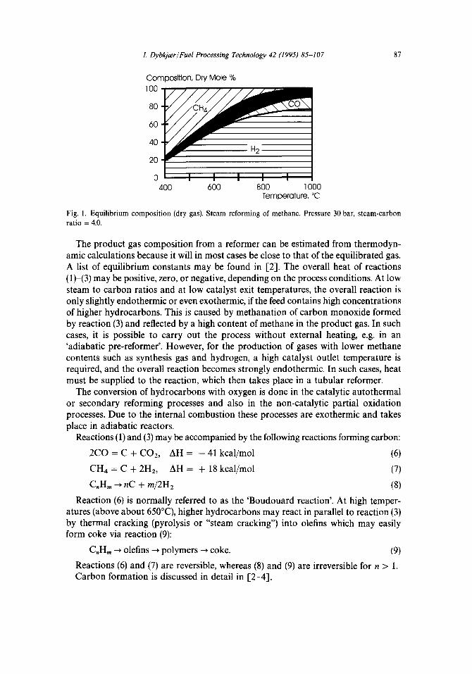
reversible at reforming temperatures, while reaction (3) is irreversible and proceeds to full conversion of the higher hydrocarbons. Reaction (4) is the difference between reaction (1) and reaction (2). It is evident, from the principle of Le Chatelier, that at higher temperatures less methane and more carbon monoxide are present in the equilibrium gas, and that methane content increases with pressure and decreases with increasing ratio of steam to carbon. This is illustrated in Fig. 1 [l].
I. DybkjmlFuel Processing Technology 42 (1995) 85-107
Composition, Dry Mole % 100
80
60
40
400 600 800 1000 TemDerature, “C
87
Fig. 1. Equilibrium composition (dry gas). Steam reforming of methane. Pressure 30 bar, steam-carbon ratio = 4.0.
The product gas composition from a reformer can be estimated from thermodyn- amic calculations because it will in most cases be close to that of the equilibrated gas. A list of equilibrium constants may be found in [2]. The overall heat of reactions (l)-(3) may be positive, zero, or negative, depending on the process conditions. At low steam to carbon ratios and at low catalyst exit temperatures, the overall reaction is only slightly endothermic or even exothermic, if the feed contains high concentrations of higher hydrocarbons. This is caused by methanation of carbon monoxide formed by reaction (3) and reflected by a high content of methane in the product gas. In such cases, it is possible to carry out the process without external heating, e.g. in an ‘adiabatic pre-reformer’. However, for the production of gases with lower methane contents such as synthesis gas and hydrogen, a high catalyst outlet temperature is required, and the overall reaction becomes strongly endothermic. In such cases, heat must be supplied to the reaction, which then takes place in a tubular reformer.
The conversion of hydrocarbons with oxygen is done in the catalytic autothermal or secondary reforming processes and also in the non-catalytic partial oxidation processes. Due to the internal combustion these processes are exothermic and takes place in adiabatic reactors.
Reactions (1) and (3) may be accompanied by the following reactions forming carbon:
2co = c + coz, AH = - 41 kcal/mol (6) CH4 = C + 2Hz, AH = + 18 kcal/mol (7) C,H, -+ nC + m/2Hz (8)
Reaction (6) is normally referred to as the ‘Boudouard reaction’. At high temper- atures (above about 65o”C), higher hydrocarbons may react in parallel to reaction (3) by thermal cracking (pyrolysis or “steam cracking”) into olefins which may easily form coke via reaction (9):
C,H, + olefins + polymers + coke. (9) Reactions (6) and (7) are reversible, whereas (8) and (9) are irreversible for n > 1. Carbon formation is discussed in detail in [Z-4].
88 I. DybQzrlFuel Processing Technology 42 (1995) 85-107
3. Tubular, fired reforming
3.1. Mechanical design
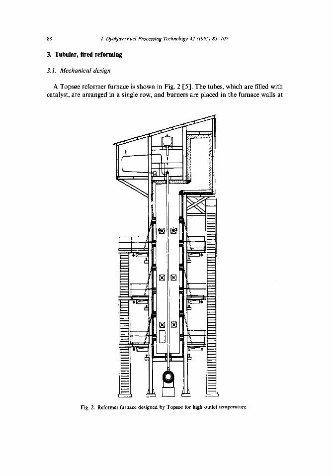
A Topsere reformer furnace is shown in Fig. 2 [S]. The tubes, which are filled with catalyst, are arranged in a single row, and burners are placed in the furnace walls at
Fig. 2. Reformer furnace designed by Topwe for high outlet temperature.
I. DybkjazrlFuel Processing Technology 42 (I 995) 85-107 89
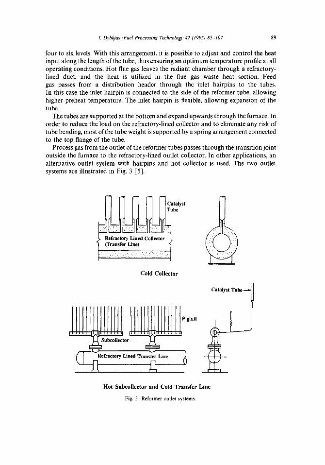
four to six levels. With this arrangement, it is possible to adjust and control the heat input along the length of the tube, thus ensuring an optimum temperature profile at all operating conditions. Hot flue gas leaves the radiant chamber through a refractory- lined duct, and the heat is utilized in the flue gas waste heat section. Feed gas passes from a distribution header through the inlet hairpins to the tubes. In this case the inlet hairpin is connected to the side of the reformer tube, allowing higher preheat temperature. The inlet hairpin is flexible, allowing expansion of the tube.
The tubes are supported at the bottom and expand upwards through the furnace. In order to reduce the load on the refractory-lined collector and to eliminate any risk of tube bending, most of the tube weight is supported by a spring arrangement connected to the top flange of the tube.
Process gas from the outlet of the reformer tubes passes through the transition joint outside the furnace to the refractory-lined outlet collector. In other applications, an alternative outlet system with hairpins and hot collector is used. The two outlet systems are illustrated in Fig. 3 [S].
Catalyst TUbe Lk .I :;
_.;., .:,::.:
Cold Collector
Catalyst Tube -
Pigtail
V
fractow Lined Transfer Line 1
Hot Subcollector and Cold Transfer Line
Fig. 3. Reformer outlet systems.
90 I. Dybkjter/Fuel Processing Technology 42 (1995) 85-107
3.2. Gas composition
The gas composition at the outlet of the reformer is strongly influenced by the process conditions. Therefore it is essential to consider the steam reformer not only as a furnace but also as a chemical reactor. The most important variables are: (i) hydrocarbon feed characteristics; (ii) inlet steam to carbon ratio; (iii) outlet tem- perature; (iv) outlet pressure.
The feed to the reformer can be any hydrocarbon ranging from a hydrogen-rich off-gas or natural gas to heavy naphtha. In some cases it is also advantageous to add carbon dioxide at the inlet of the reformer in order to save hydrocarbon feedstock and decrease the hydrogen to carbon monoxide ratio in the product gas. In such cases the carbon dioxide from the outlet of the reformer is recycled, and extra carbon dioxide may be imported when available.
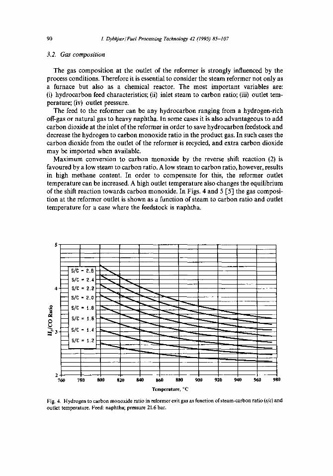
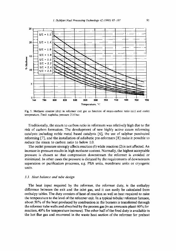
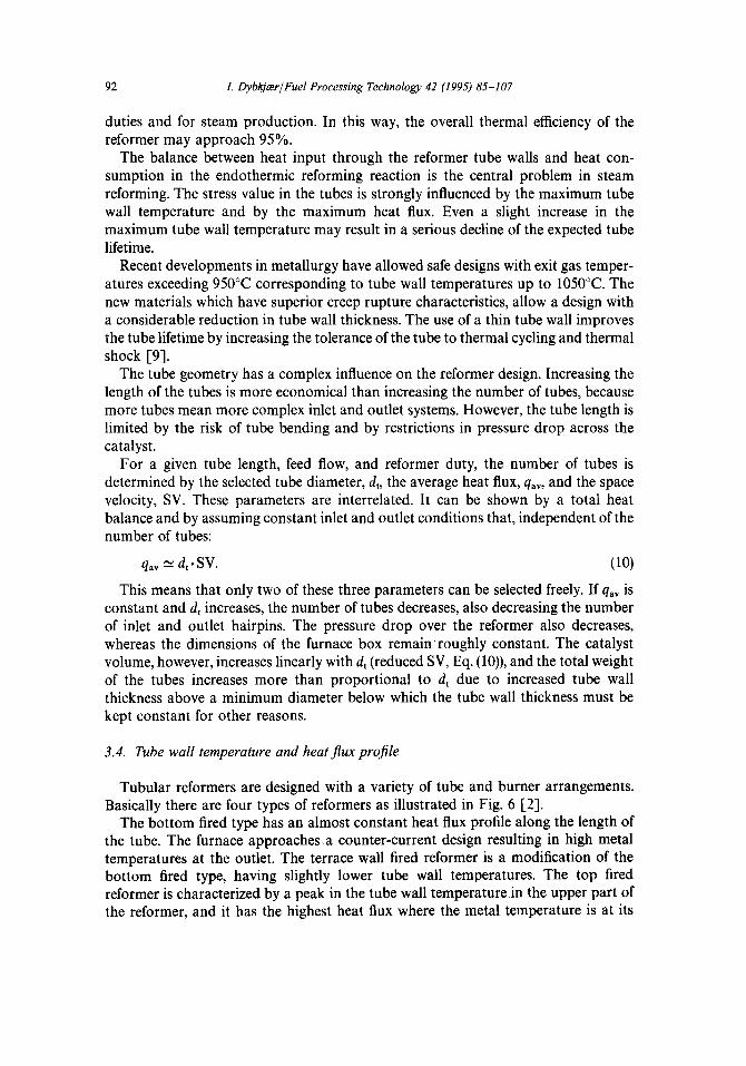
Maximum conversion to carbon monoxide by the reverse shift reaction (2) is favoured by a low steam to carbon ratio. A low steam to carbon ratio, however, results in high methane content. In order to compensate for this, the reformer outlet temperature can be increased. A high outlet temperature also changes the equilibrium of the shift reaction towards carbon monoxide. In Figs. 4 and 5 [S] the gas composi- tion at the reformer outlet is shown as a function of steam to carbon ratio and outlet temperature for a case where the feedstock is naphtha.
840 8&l 880 960 9io 9kl 9bo 9tio
Temperature, “C
Fig. 4. Hydrogen to carbon monoxide ratio in reformer exit gas as function of steam-carbon ratio (s/c) and outlet temperature. Feed: naphtha; pressure 21.6 bar.
I. DybkjmJFuel Processing Technology 42 (1995) 85-107
25
Of I I I I I I I I I I 760 780 800 820 840 860 880 900 920 940 960 980
Temperature, “C
Fig. 5. Methane content (dry) in reformer exit gas as function of steam-carbon ratio (s/c) and outlet temperature. Feed: naphtha; pressure 21.6 bar.
Traditionally, the steam to carbon ratio in reformers was relatively high due to the risk of carbon formation. The development of new highly active steam reforming catalysts including noble metal based catalysts [6], the use of sulphur passivated reforming [7], and the installation of adiabatic pre-reformers [8] make it possible to reduce the steam to carbon ratio to below 1.0.
The outlet pressure strongly affects reaction (1) while reaction (2) is not affected. An increase in pressure results in high methane content. Normally, the highest acceptable pressure is chosen so that compression downstream the reformer is avoided or minimized. In other cases the pressure is dictated by the requirements of downstream separation or purification processes, e.g. PSA units, membrane units or cryogenic units.
3.3. Heat balance and tube design
The heat input required by the reformer, the reformer duty, is the enthalpy difference between the exit and the inlet gas, and it can easily be calculated from enthalpy tables. The duty consists of heat of reaction as well as heat required to raise the temperature to the level of the reformer exit. In a typical tubular reformer furnace, about 50% of the heat produced by combustion in the burners is transferred through the reformer tube walls and absorbed by the process gas (in an ammonia plant: 60% for reaction, 40% for temperature increase). The other half of the fired duty is available in the hot flue gas and recovered in the waste heat section of the reformer for preheat
92 I. Llybkjar/Fuel Processing Technology 42 (199.5) 85-107
duties and for steam production. In this way, the overall thermal efficiency of the reformer may approach 95%.
The balance between heat input through the reformer tube walls and heat con- sumption in the endothermic reforming reaction is the central problem in steam reforming. The stress value in the tubes is strongly influenced by the maximum tube wall temperature and by the maximum heat flux. Even a slight increase in the maximum tube wall temperature may result in a serious decline of the expected tube lifetime.
Recent developments in metallurgy have allowed safe designs with exit gas temper- atures exceeding 950°C corresponding to tube wall temperatures up to 1050°C. The new materials which have superior creep rupture characteristics, allow a design with a considerable reduction in tube wall thickness. The use of a thin tube wall improves the tube lifetime by increasing the tolerance of the tube to thermal cycling and thermal shock [9].
The tube geometry has a complex influence on the reformer design. Increasing the length of the tubes is more economical than increasing the number of tubes, because more tubes mean more complex inlet and outlet systems. However, the tube length is limited by the risk of tube bending and by restrictions in pressure drop across the catalyst.
For a given tube length, feed flow, and reformer duty, the number of tubes is determined by the selected tube diameter, d,, the average heat flux, qav, and the space velocity, SV. These parameters are interrelated. It can be shown by a total heat balance and by assuming constant inlet and outlet conditions that, independent of the number of tubes:
qay = d, * sv. (10)
This means that only two of these three parameters can be selected freely. If qav is constant and d, increases, the number of tubes decreases, also decreasing the number of inlet and outlet hairpins. The pressure drop over the reformer also decreases, whereas the dimensions of the furnace box remain’roughly constant. The catalyst volume, however, increases linearly with d, (reduced SV, Eq. (lo)), and the total weight of the tubes increases more than proportional to d, due to increased tube wall thickness above a minimum diameter below which the tube wall thickness must be kept constant for other reasons.
3.4. Tube wall temperature and heat JIux projile
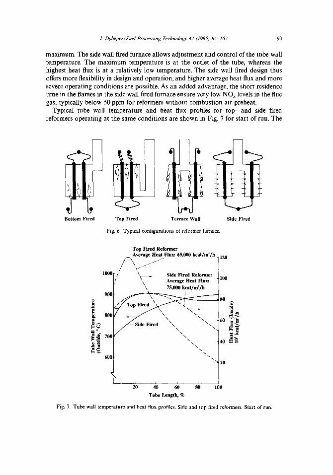
Tubular reformers are designed with a variety of tube and burner arrangements. Basically there are four types of reformers as illustrated in Fig. 6 [Z].
The bottom fired type has an almost constant heat flux profile along the length of the tube. The furnace appr0aches.a counter-current design resulting in high metal temperatures at the outlet. The terrace wall fired reformer is a modification of the bottom fired type, having slightly lower tube wall temperatures. The top fired reformer is characterized by a peak in the tube wall temperature in the upper part of the reformer, and it has the highest heat flux where the metal temperature is at its
1. DybkjmlFuel Processing Technology 42 (1995) 85-107 93
maximum. The side wall fired furnace allows adjustment and control of the tube wall temperature. The maximum temperature is at the outlet of the tube, whereas the highest heat flux is at a relatively low temperature. The side wall fired design thus offers more flexibility in design and operation, and higher average heat flux and more severe operating conditions are possible. As an added advantage, the short residence time in the flames in the side wall fired furnace ensure very low NO, levels in the flue gas, typically below 50 ppm for reformers without combustion air preheat.
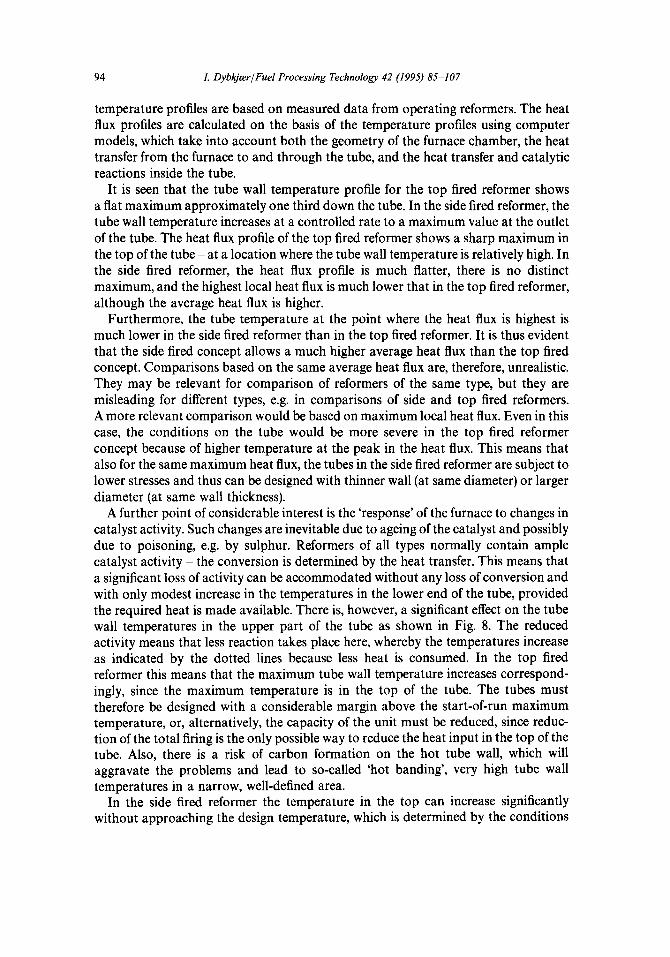
Typical tube wall temperature and heat flux profiles for top- and side fired reformers operating at the same conditions are shown in Fig. 7 for start of run. The
Bottom Fired Top Fired Terrace Wall Side Fired
Fig. 6. Typical configurations of reformer furnace.
Top Fired Reformer Average Heat Flux: 65,000 kcsl/m’/h
/-\ / ,120
lOOO-,’
/ \/ \
/ Y-
Side Fired Reformer loo Average Heat Flux:
\ 75,000 kcal/m’/h
600 -
1 I I
20 40 60 80 100 Tube Length, %
Fig. 7. Tube wall temperature and heat flux profiles. Side and top fired reformers. Start of run.
94 I. DybkjmlFuel Processing Technology 42 (1995) 85-107
temperature profiles are based on measured data from operating reformers. The heat flux profiles are calculated on the basis of the temperature profiles using computer models, which take into account both the geometry of the furnace chamber, the heat transfer from the furnace to and through the tube, and the heat transfer and catalytic reactions inside the tube.
It is seen that the tube wall temperature profile for the top fired reformer shows a flat maximum approximately one third down the tube. In the side fired reformer, the tube wall temperature increases at a controlled rate to a maximum value at the outlet of the tube. The heat flux profile of the top fired reformer shows a sharp maximum in the top of the tube - at a location where the tube wall temperature is relatively high. In the side fired reformer, the heat flux profile is much flatter, there is no distinct maximum, and the highest local heat flux is much lower that in the top fired reformer, although the average heat flux is higher.
Furthermore, the tube temperature at the point where the heat flux is highest is much lower in the side fired reformer than in the top fired reformer. It is thus evident that the side fired concept allows a much higher average heat flux than the top fired concept. Comparisons based on the same average heat flux are, therefore, unrealistic. They may be relevant for comparison of reformers of the same type, but they are misleading for different types, e.g. in comparisons of side and top fired reformers. A more relevant comparison would be based on maximum local heat flux. Even in this case, the conditions on the tube would be more severe in the top fired reformer concept because of higher temperature at the peak in the heat flux. This means that also for the same maximum heat flux, the tubes in the side fired reformer are subject to lower stresses and thus can be designed with thinner wall (at same diameter) or larger diameter (at same wall thickness).
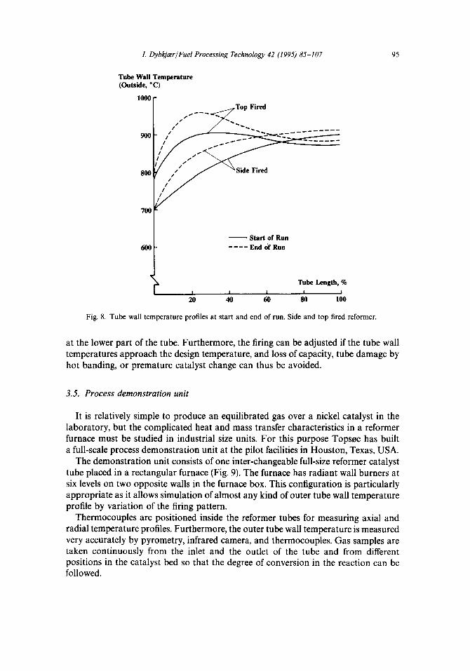
A further point of considerable interest is the ‘response’ of the furnace to changes in catalyst activity. Such changes are inevitable due to ageing of the catalyst and possibly due to poisoning, e.g. by sulphur. Reformers of all types normally contain ample catalyst activity - the conversion is determined by the heat transfer. This means that a significant loss of activity can be accommodated without any loss of conversion and with only modest increase in the temperatures in the lower end of the tube, provided the required heat is made available. There is, however, a significant effect on the tube wall temperatures in the upper part of the tube as shown in Fig. 8. The reduced activity means that less reaction takes place here, whereby the temperatures increase as indicated by the dotted lines because less heat is consumed. In the top fired reformer this means that the maximum tube wall temperature increases correspond- ingly, since the maximum temperature is in the top of the tube. The tubes must therefore be designed with a considerable margin above the start-of-run maximum temperature, or, alternatively, the capacity of the unit must be reduced, since reduc- tion of the total firing is the only possible way to reduce the heat input in the top of the tube. Also, there is a risk of carbon formation on the hot tube wall, which will aggravate the problems and lead to so-called ‘hot banding’, very high tube wall temperatures in a narrow, well-defined area.
In the side fired reformer the temperature in the top can increase significantly without approaching the design temperature, which is determined by the conditions
I. LlybkjazrlFuel Processing Technology 42 (1995) M-107 95
Tube Wall Temperature (Outside, “C)
lOOO-
600- - Start of Run ----End df Run
Tube Length, % I 1 1 I ,
20 40 60 80 100
Fig. 8. Tube wall temperature profiles at start and end of run. Side and top fired reformer.
at the lower part of the tube. Furthermore, the firing can be adjusted if the tube wall temperatures approach the design temperature, and loss of capacity, tube damage by hot banding, or premature catalyst change can thus be avoided.
3.5. Process demonstration unit
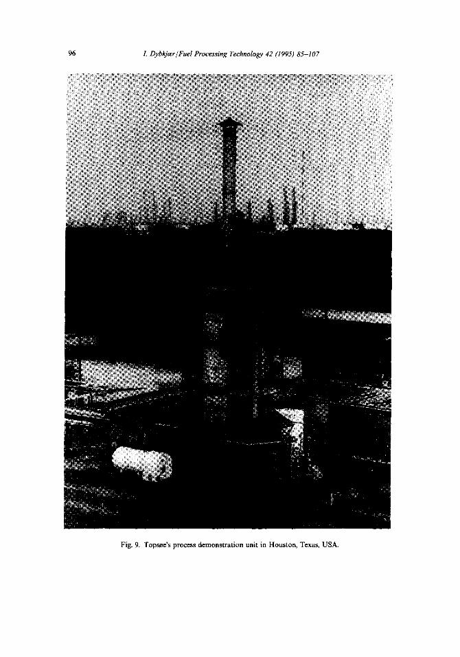
It is relatively simple to produce an equilibrated gas over a nickel catalyst in the laboratory, but the complicated heat and mass transfer characteristics in a reformer furnace must be studied in industrial size units. For this purpose Topsse has built a full-scale process demonstration unit at the pilot facilities in Houston, Texas, USA.
The demonstration unit consists of one inter-changeable full-size reformer catalyst tube placed in a rectangular furnace (Fig. 9). The furnace has radiant wall burners at six levels on two opposite walls in the furnace box. This configuration is particularly appropriate as it allows simulation of almost any kind of outer tube wall temperature profile by variation of the firing pattern.
Thermocouples are positioned inside the reformer tubes for measuring axial and radial temperature profiles. Furthermore, the outer tube wall temperature is measured very accurately by pyrometry, infrared camera, and thermocouples. Gas samples are taken continuously from the inlet and the outlet of the tube and from different positions in the catalyst bed so that the degree of conversion in the reaction can be followed.
96 I. Dybl@r/Fuel Processing Technology 42 (1995) 85-107
Fig. 9. Topsee’s process demonstration unit in Houston, Texas, USA.
I. Dybkjmrl Fuel Processing Technology 42 (I 995) 85-107 91
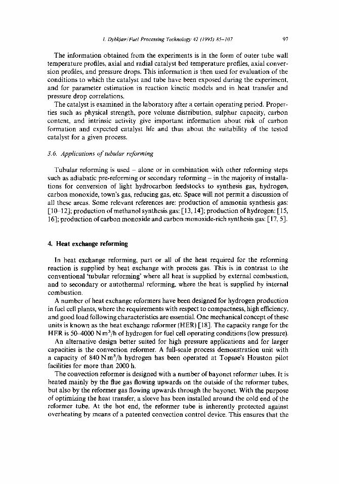
The information obtained from the experiments is in the form of outer tube wall temperature profiles, axial and radial catalyst bed temperature profiles, axial conver- sion profiles, and pressure drops. This information is then used for evaluation of the conditions to which the catalyst and tube have been exposed during the experiment, and for parameter estimation in reaction kinetic models and in heat transfer and pressure drop correlations.
The catalyst is examined in the laboratory after a certain operating period. Proper- ties such as physical strength, pore volume distribution, sulphur capacity, carbon content, and intrinsic activity give important information about risk of carbon formation and expected catalyst life and thus about the suitability of the tested catalyst for a given process.
3.6. Applications of tubular reforming
Tubular reforming is used - alone or in combination with other reforming steps such as adiabatic pre-reforming or secondary reforming - in the majority of installa- tions for conversion of light hydrocarbon feedstocks to synthesis gas, hydrogen, carbon monoxide, town’s gas, reducing gas, etc. Space will not permit a discussion of all these areas. Some relevant references are: production of ammonia synthesis gas: [l&12]; production of methanol synthesis gas: [13,14]; production of hydrogen: [15, 163; production of carbon monoxide and carbon monoxide-rich synthesis gas: [17,5].
4. Heat exchange reforming
In heat exchange reforming, part or all of the heat required for the reforming reaction is supplied by heat exchange with process gas. This is in contrast to the conventional ‘tubular reforming’ where all heat is supplied by external combustion, and to secondary or autothermal reforming, where the heat is supplied by internal combustion.
A number of heat exchange reformers have been designed for hydrogen production in fuel cell plants, where the requirements with respect to compactness, high efficiency, and good load following characteristics are essential. One mechanical concept of these units is known as the heat exchange reformer (HER) [18]. The capacity range for the HER is 504000 N m3/h of hydrogen for fuel cell operating conditions (low pressure).
An alternative design better suited for high pressure applications and for larger capacities is the convection reformer. A full-scale process demonstration unit with a capacity of 840 Nm3/h hydrogen has been operated at Topsoe’s Houston pilot facilities for more than 2000 h.
The convection reformer is designed with a number of bayonet reformer tubes. It is heated mainly by the flue gas flowing upwards on the outside of the reformer tubes, but also by the reformer gas flowing upwards through the bayonet. With the purpose of optimizing the heat transfer, a sleeve has been installed around the cold end of the reformer tube. At the hot end, the reformer tube is inherently protected against overheating by means of a patented convection control device. This ensures that the
98 I. Dybkja?rlFuel Processing Technology 42 (1995) 85-107
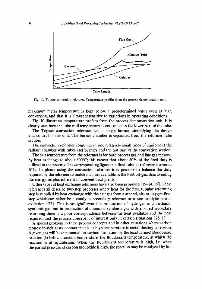
Tube Length
Fig. 10. Topsee convection reformer. Temperature profiles from the process demonstration unit.
maximum metal temperature is kept below a predetermined value even at high conversion, and that it is almost insensitive to variations in operating conditions.
Fig. 10 illustrates temperature profiles from the process demonstration unit. It is clearly seen how the tube wall temperature is controlled in the lower part of the tube.
The Topsse convection reformer has a single burner, simplifying the design and control of the unit. The burner chamber is separated from the reformer tube section.
The convection reformer combines in one relatively small piece of equipment the radiant chamber with tubes and burners and the hot part of the convection section.
The exit temperature from the reformer is for both process gas and flue gas reduced by heat exchange to about 600°C; this means that about 80% of the fired duty is utilized in the process. The corresponding figure in a fired tubular reformer is around 50%. In plants using the convection reformer it is possible to balance the duty required by the reformer to match the heat available in the PSA off-gas, thus avoiding the energy surplus inherent in conventional plants.
Other types of heat exchange reformers have also been proposed [ 19-24,151. These references all describe two-step processes where heat for the first, tubular reforming step is supplied by heat exchange with the exit gas from a second, air- or oxygen-fired step which can either be a catalytic, secondary reformer or a non-catalytic partial oxidation [23]. This is straightforward in production of hydrogen and methanol synthesis gas, but in production of ammonia synthesis gas with air-fired secondary reforming there is a poor correspondence between the heat available and the heat required, and the process concept is of interest only in certain situations [25, 11.
A special problem in these process concepts and in other situations where carbon monoxide-rich gases contact metals at high temperature is metal dusting corrosion. .A given gas will have potential for carbon formation by the (exothermic) Boudouard reaction (6) below a certain temperature, the Boudouard temperature, at which the reaction is at equilibrium. When the Boudouard temperature is high, i.e. when the partial pressure of carbon monoxide is high, the reaction may be catalyzed by hot
I. Dybkjcw/Fuel Processing Technology 42 (1995) M-107 99
metal surfaces. It is thus important that a gas with a high Boudouard temperature does not come into contact with a metal surface with a temperature below, but close to Boudouard temperature. In an operating reformer, the catalyst outlet temperature will always be above Boudouard temperature (because carbon would otherwise be formed on the catalyst). A temperature drop in the reformer outlet system or in the cooling channels of the heat exchange reformer could, however, bring the product gas below the Boudouard temperature, i.e. into an area where carbon may be formed on the metal surface.
At most conditions, Fe-Ni-Cr alloys are protected against carburization by an oxide layer. However, if this film is destroyed, a catastrophic corrosion can occur [26,27]. The corrosion starts by pointwise attack, probably by carburization at defects in the oxide layer. The corrosion products can easily be eroded and holes are formed in the material similar to pitting.
5. Adiabatic pre-reforming
Adiabatic pre-reforming is used for reforming of hydrocarbon feedstocks ranging from natural gas to heavy naphtha with final boiling points above 200°C and aromatics content above 30%. The process is carried out in a fixed bed adiabatic reactor upstream the tubular reformer. The reactor is loaded with a highly active reforming catalyst.
In the pre-reformer, higher hydrocarbons are completely converted into a mixture of carbon oxides, hydrogen and methane. Fundamentals of the process are discussed in [28].
If the feedstock is natural gas, the overall process is endothermic, resulting in a temperature drop. For heavier feedstocks such as naphtha the overall process is exothermic or thermoneutral.
Since the operating temperature of the pre-reforming catalyst is relatively low, the equilibrium for chemisorption of sulphur on the Ni-based catalyst is favourable. Tr ace s of sulphur leaking from the desulphurization section are quantitatively removed from the feed gas, giving a completely sulphur-free feed to the tubular reformer.
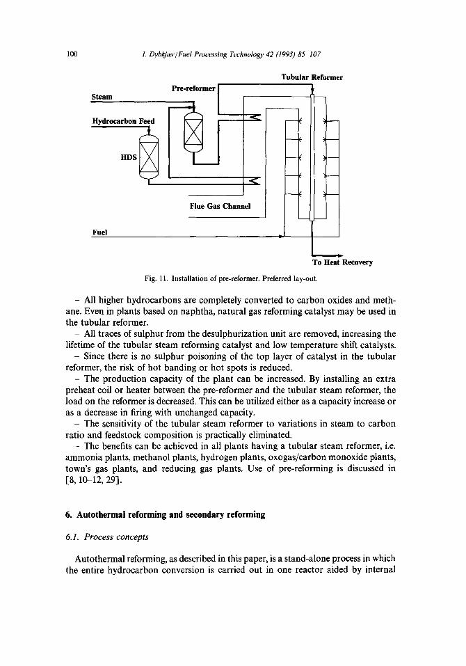
Fig. 11 shows the preferred solution for debottlenecking or revamp of existing plants and the most common process lay-out in new plants. By reheating the pre-reformer effluent to 650°C the required heat duty in the tubular reformer is decreased by up to 25%.
The installation of a pre-reformer in an existing plant is very simple since there is no change in the hot end of the tubular reformer. Most of the new equipment can be installed while the plant is in operation. If a new coil is to be installed in the flue gas waste heat section, this can be done during a scheduled shutdown.
If no modifications of existing coils are made, and no new preheat coils are installed, the duty of the tubular reformer will not change. However, the pre-reformer will act as a guard for the tubular reformer, and it will facilitate changes in operating conditions, e.g. reduction of steam to carbon ratio, and variations in feedstock.
The installation of an adiabatic pre-reformer upstream a steam reformer gives a number of benefits:
100 I. Dyb&zr/Fuel Processing Technology 42 (1995) 85-107
Tubular Reformer
Steam
Hvdrocarbon Feed
Fuel
Flue Gas Channel
I .
To Heat Recovery
Fig. 11. Installation of pre-reformer. Preferred lay-out.
- All higher hydrocarbons are completely converted to carbon oxides and meth- ane. Even in plants based on naphtha, natural gas reforming catalyst may be used in the tubular reformer.
- All traces of sulphur from the desulphurization unit are removed, increasing the lifetime of the tubular steam reforming catalyst and low temperature shift catalysts.
- Since there is no sulphur poisoning of the top layer of catalyst in the tubular reformer, the risk of hot banding or hot spots is reduced.
- The production capacity of the plant can be increased. By installing an extra preheat coil or heater between the pre-reformer and the tubular steam reformer, the load on the reformer is decreased. This can be utilized either as a capacity increase or as a decrease in firing with unchanged capacity.
_ The sensitivity of the tubular steam reformer to variations in steam to carbon ratio and feedstock composition is practically eliminated.
- The benefits can be achieved in all plants having a tubular steam reformer, i.e. ammonia plants, methanol plants, hydrogen plants, oxogas/carbon monoxide plants, town’s gas plants, and reducing gas plants. Use of pre-reforming is discussed in [&lo-12, 29).
6. Autothermal reforming and secondary reforming
6. I. Process concepts
Autothermal reforming, as described in this paper, is a stand-alone process in which the entire hydrocarbon conversion is carried out in one reactor aided by internal
I. DybkjwlFuel Processing Technology 42 (1995) 85-107 101
combustion with oxygen. Secondary reforming is a process in which partially con- verted process gas form a primary (tubular) reformer is further converted by internal combustion. The secondary reformer in ammonia plants will typically be air-blown while in methanol plants it will be oxygen-blown. The concentration of combustibles in the feed to the autothermal reformers is higher than in the feed to the secondary reformers. Therefore, flow conditions, the heat release, and the risk of soot formation are different in the autothermal and secondary reformers resulting in different require- ments to burner and reactor design.
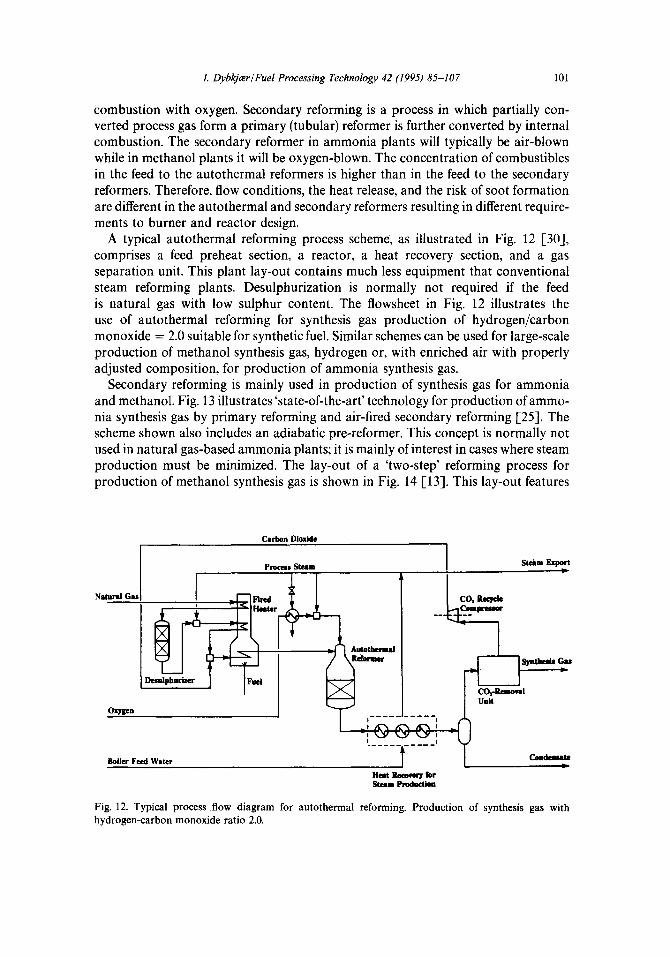
A typical autothermal reforming process scheme, as illustrated in Fig. 12 [30], comprises a feed preheat section, a reactor, a heat recovery section, and a gas separation unit. This plant lay-out contains much less equipment that conventional steam reforming plants. Desulphurization is normally not required if the feed is natural gas with low sulphur content. The flowsheet in Fig. 12 illustrates the use of autothermal reforming for synthesis gas production of hydrogen/carbon monoxide = 2.0 suitable for synthetic fuel. Similar schemes can be used for large-scale production of methanol synthesis gas, hydrogen or, with enriched air with properly adjusted composition, for production of ammonia synthesis gas.
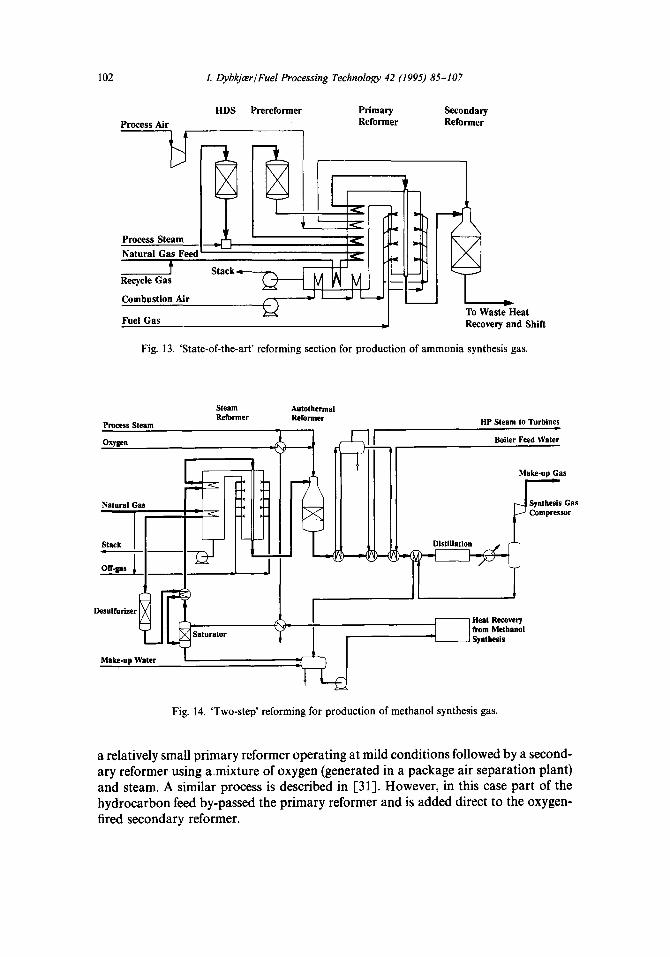
Secondary reforming is mainly used in production of synthesis gas for ammonia and methanol. Fig. 13 illustrates ‘state-of-the-art’ technology for production of ammo- nia synthesis gas by primary reforming and air-fired secondary reforming [25]. The scheme shown also includes an adiabatic pre-reformer. This concept is normally not used in natural gas-based ammonia plants; it is mainly of interest in cases where steam production must be minimized. The lay-out of a ‘two-step’ reforming process for production of methanol synthesis gas is shown in Fig. 14 [13]. This lay-out features
Carbon Dioxide
Boikr Feed Water
Fig. 12. Typical process flow diagram for autothermal reforming. Production of synthesis gas with hydrogen-carbon monoxide ratio 2.0.
102 I. DybkjcerlFuel Processing Technology 42 (1995) 85-307
Process Air HDS Prereformer Primary Secondary
Reformer Reformer
< Process Steam < Natural Gas Feed
t Stack 11:”
Recycle Gas
Combustion Air
Fuel Gas J To Waste Heat Recovery and Shih
Fig. 13. ‘State-of-the-art’ reforming section for production of ammonia synthesis gas.
Process Steam
Oxrw
Natural Gas
Boiler Feed Water
HP Steam to Turbines
_ I Heat Recovey
I
(mm Methanol
I Synthesis
Fig. 14. ‘Two-step’ reforming for production of methanol synthesis gas.
Make-up Gas
a relatively small primary reformer operating at mild conditions followed by a second- ary reformer using a.mixture of oxygen (generated in a package air separation plant) and steam. A similar process is described in [31]. However, in this case part of the hydrocarbon feed by-passed the primary reformer and is added direct to the oxygen- fired secondary reformer.
I. DybkjmlFuel Processing Technology 42 (1995) 85-107 103
6.2. Reactor design
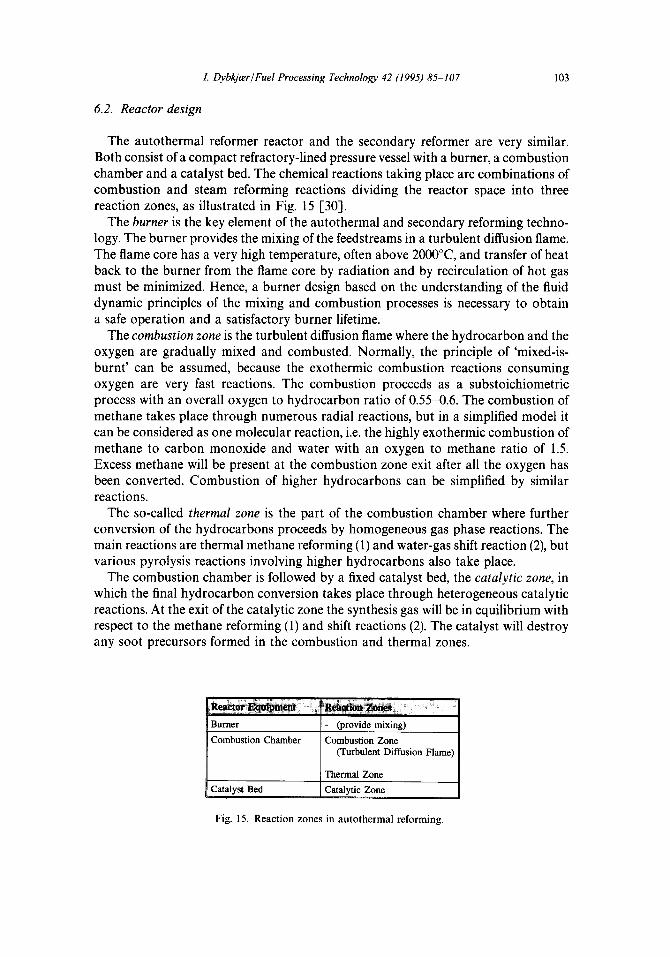
The autothermal reformer reactor and the secondary reformer are very similar. Both consist of a compact refractory-lined pressure vessel with a burner, a combustion chamber and a catalyst bed. The chemical reactions taking place are combinations of combustion and steam reforming reactions dividing the reactor space into three reaction zones, as illustrated in Fig. 15 [30].
The burner is the key element of the autothermal and secondary reforming techno- logy. The burner provides the mixing of the feedstreams in a turbulent diffusion flame. The flame core has a very high temperature, often above 2OOo”C, and transfer of heat back to the burner from the flame core by radiation and by recirculation of hot gas must be minimized. Hence, a burner design based on the understanding of the fluid dynamic principles of the mixing and combustion processes is necessary to obtain a safe operation and a satisfactory burner lifetime.
The combustion zone is the turbulent diffusion flame where the hydrocarbon and the oxygen are gradually mixed and combusted. Normally, the principle of ‘mixed-is- burnt’ can be assumed, because the exothermic combustion reactions consuming oxygen are very fast reactions. The combustion proceeds as a substoichiometric process with an overall oxygen to hydrocarbon ratio of 0.55-0.6. The combustion of methane takes place through numerous radial reactions, but in a simplified model it can be considered as one molecular reaction, i.e. the highly exothermic combustion of methane to carbon monoxide and water with an oxygen to methane ratio of 1.5. Excess methane will be present at the combustion zone exit after all the oxygen has been converted. Combustion of higher hydrocarbons can be simplified by similar reactions.
The so-called thermal zone is the part of the combustion chamber where further conversion of the hydrocarbons proceeds by homogeneous gas phase reactions. The main reactions are thermal methane reforming (1) and water-gas shift reaction (2), but various pyrolysis reactions involving higher hydrocarbons also take place.
The combustion chamber is followed by a fixed catalyst bed, the catalytic zone, in which the final hydrocarbon conversion takes place through heterogeneous catalytic reactions. At the exit of the catalytic zone the synthesis gas will be in equilibrium with respect to the methane reforming (1) and shift reactions (2). The catalyst will destroy any soot precursors formed in the combustion and thermal zones.
Catalyst Bed
Thermal Zone
I Catalvtic Zone
Fig. 15. Reaction zones in autothermal reforming.
104 I. LIybkjwlFuel Processing Technology 42 (1995) 85-107
The top of the catalyst bed is exposed to the process gas leaving the combustion chamber at temperatures of llOO-14OO”C, and high thermal stability of the catalyst and the carrier system is required. A nickel catalyst supported by a magnesia-alumina spine1 carrier has shown high stability and activity for operation in autothermal and secondary reformers. The reactions are mainly controlled by film diffusion at the outer catalyst pellet surface, meaning that the process can be carried out at very high space velocities. In practice the catalyst volume is determined by optimal flow distribution and pressure drop in the reactor.
6.3. Pilot plant
A pilot plant was built for testing and demonstration of new process and reaction engineering developments in the autothermal reforming technology. The plant was designed for operation on natural gas and pure oxygen at a capacity corresponding to 100 Nm3/h natural gas producing synthesis gas (carbon monoxide + hydrogen) in the range of 250-300 N m3/h. Mixtures of natural gas and butane are also applied as feedstocks.
The scale of the pilot plant was chosen in order to enable reliable adiabatic tests of the highly exothermic combustion process. In laboratory-scale equipment it is difficult to carry out adiabatic as well as isothermal experiments on methane oxidation.
Pilot plant testing also provides the advantages that development of the combus- tion equipment (burner, combustion chamber and refractory) can be made at realistic conditions which is required for the scale-up to larger industrial plants.
The pilot plant has been in operation for three years, and recent tests have shown that trouble-free operation is possible at very low steam to carbon ratios, at high equilibrium temperatures, as well as at high addition of carbon dioxide feed. Synthesis gases with a hydrogen to carbon monoxide ratio below 1.0 have been produced [30].
6.4. Development of burner and combustion chamber
Although autothermal reformer burners of conventional design are operating industrially with satisfactory lifetime, the pilot testing revealed that for production of carbon monoxide-rich synthesis gas a more resistant burner design was required. A new generation within the burner technology, the CTS burner [32], was developed using the following tools: (i) computational fluid dynamics (CFD); (ii) isothermal physical modelling (hydraulic modelling); (iii) pilot plant testing.
The CFD calculations of the flame, the region near the burner nozzles and the whole combustion chamber were made with the LCFDSFLOW3D program. The calculations were supported by isothermal physical modelling experiments with acid and alkali simulating the mixing in the flame. The performance of various burner models was predicted by CFD calculations and verified in the pilot plant, and the results were used to optimize the burner design into the new CTS burner technology. The CTS burner design is patent-pending in countries worldwide.
I. DybkjmlFuel Processing Technology 42 (I 995) 85-I 07 105
In the design of the burner and the combustion chamber, the following reaction engineering aspects are of general importance: (i) effective mixing at the burner nozzles; (ii) low metal temperatures of the burner; (iii) soot-free combustion; (iv) homogeneous gas and temperature distribution at the entrance to the catalyst bed; (v) protection of the refractory from the hot flame core.
Recirculation of the reacted gas from the thermal zone back to the burner can protect the refractory and the burner from the hot flame core and ensure a homogene- ous gas and temperature distribution at the entrance to the catalyst bed.
The CTS burner technology can be used both for new plants and for revamp of existing plants, e.g. for boosting the production capacity. In a modified version the CTS burner may be used also in secondary reformers. Industrially, CTS burners have been used in recent revamps of existing autothermal reformers. After 1 year in operation the CTS burner at one of the plants was inspected. It showed no sign of wear or corrosion indicating much improved burner performance and extended burner lifetime.
Use of autothermal reforming is discussed in [30, 331.
7. Alternative processes
Recently, investigations at atmospheric pressure on catalytic methane oxidation to carbon monoxide and hydrogen through mild exothermic partial oxidation (5) have been published, claiming high selectivity [34-361.
In all cases formation of carbon dioxide and water is reported, demonstrating that the catalysts are active for methane reforming (l), for shift conversion (2), and also for complete oxidation to carbon dioxide. The apparent selectivity for partial oxidation (5) can be explained by the equilibrium for the methane reforming and the shift reactions favouring formation of carbon monoxide and hydrogen at atmospheric pressure and temperature above 800°C. The data reported in [36] correspond to the chemical equilibrium at the measured temperature. Some degree of complete combus- tion has taken place as the oxygen conversion is higher than that corresponding to partial oxidation. The experiments described in [35] showed that carbon monoxide and hydrogen were the primary products, and accordingly it was possible to obtain a product gas with a lower hydrogen to carbon monoxide ratio than predicted at equilibrium. However, these experiments showed only partial methane conversion and high consumption of oxygen. In [34] is reported high yields of carbon monoxide and hydrogen at reactor temperatures as low as 3OO”C, but investigations of the reported data have shown that these apparently high activities at low temperature can be explained by catalyst over-temperatures, i.e. the catalyst particles being hotter than the gas due to testing at low Reynolds number. A more detailed discussion of this is given in [30].
So far no catalyst has shown selectivity for methane oxidation to carbon monoxide and hydrogen at industrial conditions yielding less carbon dioxide than predicted by equilibrium, taking both methane reforming and shift conversion into account, In order to be economically attractive, catalytic methane oxidation must be carried out
106 I. LlybkjwlFuel Processing Technology 42 (1995) 85-107
at elevated pressure and at high methane conversion. Irrespective of whether a thermal burner or a catalytic burner, whether a fixed or a fluidized catalyst bed is used, the composition of the product exit gas will be determined by the thermody- namic equilibrium at the exit temperature which is determined by the adiabatic heat balance.
Another process route which has attracted much interest is direct, oxidative conversion of natural gas into useful products such as methanol or ethylene. The problems related to such processes were discussed in some detail in [l], and reference is made to that paper. The conclusion is that the chemistry of the direct, oxidative conversion of methane may well be exciting, but the process engineering requirements still represent severe obstacles before these routes may become economic alternatives to the indirect processes via synthesis gas.
8. Conclusions
Steam reforming and autothermal reforming are the most important technologies for production of synthesis gas. Important new developments with respect to both process and equipment design have recently been introduced to the industry. Alterna- tive processes such as selective oxidation of methane to carbon monoxide and hydrogen and direct conversion of methane to products such as methanol or ethylene are widely discussed, but have not yet been developed to a point where they are of industrial interest.
References
[l] Rostrup-Nielsen, J.R., Dybkjrer, I. and Christiansen, L.J., 1993. Steam reforming, opportunities and limits of the technology, In: de Lasa, H.J. et al (Eds.), Chemical Reactor Technology for Environ- mentally Safe Reactors and Products. Kluwer Academic Press, Dordrecht, pp. 249-281.
[2] Rostrup-Nielsen, J.R., 1984. Catalytic steam reforming. In: Anderson, J.R. and Boudart, M. (Eds.), Catalysis, Science and Technology. Springer, Berlin, pp. l-130.
[3] Alstrup, I., 1988. A model explaining carbon filament growth on nickel, iron and Ni-Cu alloy catalysts. J. Catal., 109: 241-251.
[4] Rostrup-Nielsen, J.R., 1993. Production of synthesis gas. Catal. Today, 19: 305-324. [S] Vannby, R., Stub Nielsen, C. and Kim, J.S., 1992. Operating experience in advanced steam reforming.
Paper presented at the Symposium on Large Chemical Plants, October 12-14, Antwerp, Belgium, pp. l-10.
[6] Rostrup-Nielsen, J.R. and Bak Hansen, J.-H., 1993. CO1-reforming of methane over transition metals. J. Catal., 144: 38-49.
[7] Rostrup-Nielsen, J.R., 1984a. Sulfur-passivated nickel catalysts for carbon-free steam reforming of methane. J. Catal., 85: 31-43.
[8] Vannby, R. and Winter-Madsen, S.E.L., 1992. Adiabatic pre-reforming. Ammonia Plant Sat, 32: 122-128.
[9] Mohri, T., Takemura, K. and Shibasaki, I., 1993. Application of advanced materials for catalyst tubes for steam reformers. Ammonia Plant Saf., 33: 86100.
[lo] Storgaard, L., 1991. Process options in natural gas steam reforming and evaluation of catalyst performance. In: Proceedings of Nitrogen ‘91, British Sulphur Conference, Copenhagen, pp 97-113.
I. DybkjwlFuel Processing Technology 42 (1995) 85-107 107
[ll] Nitrogen 1992. Reforming the front end, Nitrogen, 195: 22-36. [12] Appl, M., 1992. Modern ammonia technology: Where have we got to, where are we going? Nitrogen,
199: 5675. [13] Sogaard-Andersen, P., 1989. Review of Topsee’s methanol technology. Proceedings of World Meth-
anol Conference, Houston, XVII, pp l-20. [14] Schneider, R.V. III and Le Blanc, J.R. Jr., 1992. Choose optimal syngas route. Hydrocarbon Process.,
71(3): 51-57. [15] Johansen, T., Raghuraman, K.S. and Hackett, L.A., 1992. Trends in hydrogen plant design. Hydrocar-
bon Process., 71(8): 119-127. [16] TOPSOE TOPICS, 1993. Hydrogen, Haldor Topsne A/S, Lyngby, Denmark, pp l-10. [17] Stal, J.A., Hanson, DC., Bak Hansen, J.-H. and Udengaard, N.R., 1992. Sulfur passivated reforming
process lowers syngas Hz/CO ratio. Oil and Gas J., 90(10): 62-67. [lS] Stahl, H., Rostrup-Nielsen, J.R. and Udengaard, N.R., 1985. High efficiency heat exchange reformer.
In: Fuel Cell Seminar, Tucson, Arizona, pp. 83-88 [19] Topsae, H., 1979. Preparation of synthesis gas, particularly Ammonia-Synthesis Gas, Danish Pat.
148882. [20] Miyasugi, T., Tosaka, S., Kawai, T. and Suzuki, A., 1984. A heat-exchanger type steam reformer for
ammonia production. Ammonia Plant Saf., 25: 6468. [21] Elkins, K.J., Jeffery, I.C., Kitchen, D. and Pinto, A., 1991 The ICI gas heated reformer (GHR) system.
In: Proceedings of Nitrogen ‘91, British Sulphur Conference, Copenhagen, pp 83-95. [22] Schneider, R.V. III, 1990. Advanced in reforming system design. Fertilizer Association of India
Seminar, New Delhi, paper SII-1, pp l-7. [23] March, H.D. and Thiagarajan, N., 1993. CAR demonstration unit on stream. Ammonia Plant Saf., 33:
1088122. [24] Sosna, M., Bondar, I., Gunko, B. and Grotz, B.J., 1993. History of development of the Tandem
reforming process. AIChE Ammonia Safety Symposium, Orlando, paper 2a, pp l-15. [25] Dybkjar, I., 1990. Advances in ammonia production technology. Fertilizer Association of India
Seminar, New Delhi, paper SIII-2, pp l-18. [26] Grabke, H.J. and Wolf, I., 1987. Carburization and oxidation. Mater. Sci. Eng., 87: 23-33. [27] Grabke, H.J., Krajak, R. and Miiller-Lorenz, E.M., 1993. Metal dusting of high temperature alloys.
Werkstoffe und Korrosion, 44: 89-97. [ZS] Christensen, T.S. and Bak Hansen, J.-H., 1989. Fundamentals in design of adiabatic preconverters for
steam reforming of hydrocarbons. Paper presented at second Nordic Symposium on Catalysis, Lyngby, Denmark, pp l-l 1.
[29] Verduijn, W.D., 1993. Experience with a prereformer. Ammonia Plant Saf., 33: 165-170. [30] Christensen, T.S. and Primdahl, I.I., 1994. Improve syngas production using autothermal reforming.
Hydrocarbon Process, March: 39-46. [31] Farina, G.L. and Supp, E., 1992. Produce syngas for methanol. Hydrocarbon Process., 71(3): 77-79. [32] Christensen, T.S., Dybkjrer, I., Hansen, L. and Primdahl, I.I., 1994. Burners for secondary and
autothermal reforming ~ design and industrial performance. AIChE Ammonia Safety Meeting, Vancouver, USA, October 1994, paper No. 39.
[33] Lowson, A., Primdahl, I.I., Smith, D. and Wang, S.-I., 1990. Paper 106A presented at AIChE Spring Natl. Meeting, Orlando, pp 145.
[34] Choudhary, V.R., Rajput, A.M. and Prabhakar, B., 1992. Low temperature oxidative conversion of methane to syngas over NiO-CaO catalyst. Cat. Lett., 15: 363-370.
[35] Hickman, D.A. and Schmidt, L.D., 1992. Synthesis gas formation by direct oxidation of methane over Pt Monoliths. J. Catal., 138: 267-281.
[36] Ashcroft, A.T., Cheetham, A.K., Foord, J.S., Green, M.L.H., Grey, C.P., Murrell, A.J. and Vernon, P.D.F., 1990. Selective oxidation of methane to synthesis gas using transition metal catalysts. Nature, 344: 319-321.