Tube Screaming Preamp - GuitarPCB
4
Tube Screaming Preamp Introducing the Tube Screaming Preamp. Finally we have the coveted Tube Screamer tone now with the ability to adjust the Tone for any guitar in any situation quickly. By removing the passive tone control and inserting a Baxandall style 3 Band Active EQ along with Presence control you can now get amazing Screamer Tones never before achievable. It makes you wonder why nobody has really tried to improve on the old passive tone in one of the most talked about guitar pedals in history. Board Dimensions (W x H) 2.15” x 1.95” Build Notes: * IC: TL072 – You may also try other Dual Opamps like NE5532, 4558, Burr Brown 2134 etc... ** D1 – D2 – Clipping LEDs – Try Red, Blue or Violet for a warm tube tone or you may also try our “hand tested” Germanium Diodes for a different character. Since the circuit uses a Baxandall Active EQ you will still have enough Gain on tap. Also feel free to try Silicon Diodes as well. Socket and See! A / B Pads were added if you wish to use an off-board clipping selector like our Roto-Tone or DPDT boards.
Transcript of Tube Screaming Preamp - GuitarPCB
Tube Screaming Preamp
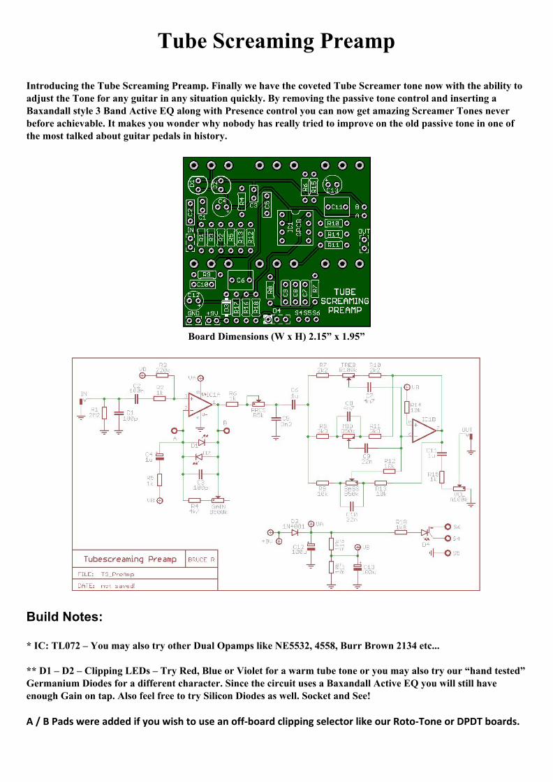
Introducing the Tube Screaming Preamp. Finally we have the coveted Tube Screamer tone now with the ability to adjust the Tone for any guitar in any situation quickly. By removing the passive tone control and inserting a Baxandall style 3 Band Active EQ along with Presence control you can now get amazing Screamer Tones never before achievable. It makes you wonder why nobody has really tried to improve on the old passive tone in one of the most talked about guitar pedals in history.
Board Dimensions (W x H) 2.15” x 1.95”
Build Notes: * IC: TL072 – You may also try other Dual Opamps like NE5532, 4558, Burr Brown 2134 etc... ** D1 – D2 – Clipping LEDs – Try Red, Blue or Violet for a warm tube tone or you may also try our “hand tested” Germanium Diodes for a different character. Since the circuit uses a Baxandall Active EQ you will still have enough Gain on tap. Also feel free to try Silicon Diodes as well. Socket and See! A / B Pads were added if you wish to use an off-board clipping selector like our Roto-Tone or DPDT boards.
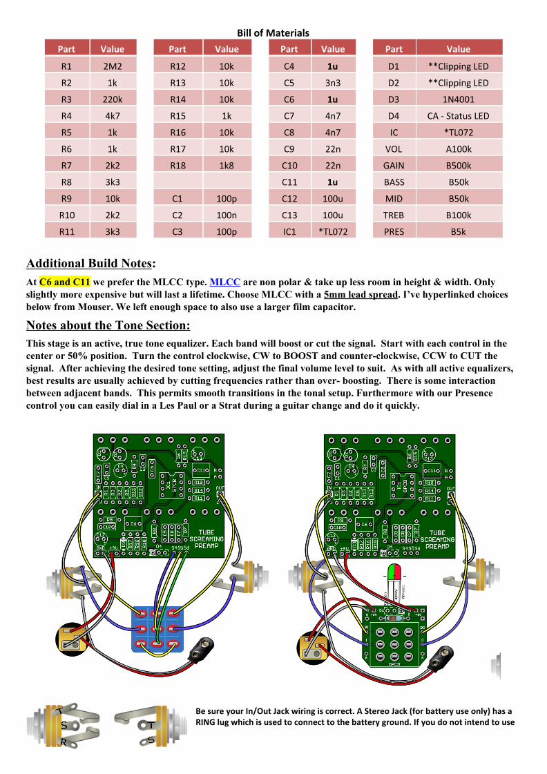
Bill of Materials
Part Value Part Value Part Value Part Value
R1 2M2 R12 10k C4 1u D1 **Clipping LED
R2 1k R13 10k C5 3n3 D2 **Clipping LED
R3 220k R14 10k C6 1u D3 1N4001
R4 4k7 R15 1k C7 4n7 D4 CA - Status LED
R5 1k R16 10k C8 4n7 IC *TL072
R6 1k R17 10k C9 22n VOL A100k
R7 2k2 R18 1k8 C10 22n GAIN B500k
R8 3k3 C11 1u BASS B50k
R9 10k C1 100p C12 100u MID B50k
R10 2k2 C2 100n C13 100u TREB B100k
R11 3k3 C3 100p IC1 *TL072 PRES B5k
Additional Build Notes: At C6 and C11 we prefer the MLCC type. MLCC are non polar & take up less room in height & width. Only slightly more expensive but will last a lifetime. Choose MLCC with a 5mm lead spread. I’ve hyperlinked choices below from Mouser. We left enough space to also use a larger film capacitor.
Notes about the Tone Section: This stage is an active, true tone equalizer. Each band will boost or cut the signal. Start with each control in the center or 50% position. Turn the control clockwise, CW to BOOST and counter-clockwise, CCW to CUT the signal. After achieving the desired tone setting, adjust the final volume level to suit. As with all active equalizers, best results are usually achieved by cutting frequencies rather than over- boosting. There is some interaction between adjacent bands. This permits smooth transitions in the tonal setup. Furthermore with our Presence control you can easily dial in a Les Paul or a Strat during a guitar change and do it quickly.
Be sure your In/Out Jack wiring is correct. A Stereo Jack (for battery use only) has a RING lug which is used to connect to the battery ground. If you do not intend to use
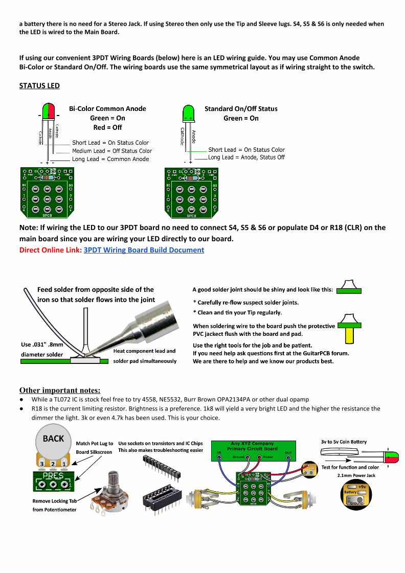
a battery there is no need for a Stereo Jack. If using Stereo then only use the Tip and Sleeve lugs. S4, S5 & S6 is only needed when the LED is wired to the Main Board.
If using our convenient 3PDT Wiring Boards (below) here is an LED wiring guide. You may use Common Anode Bi-Color or Standard On/Off. The wiring boards use the same symmetrical layout as if wiring straight to the switch. STATUS LED
Note: If wiring the LED to our 3PDT board no need to connect S4, S5 & S6 or populate D4 or R18 (CLR) on the
main board since you are wiring your LED directly to our board.
Direct Online Link: 3PDT Wiring Board Build Document
Other important notes: ● While a TL072 IC is stock feel free to try 4558, NE5532, Burr Brown OPA2134PA or other dual opamp
● R18 is the current limiting resistor. Brightness is a preference. 1k8 will yield a very bright LED and the higher the resistance the
dimmer the light. 3k or even 4.7k has been used. This is your choice.
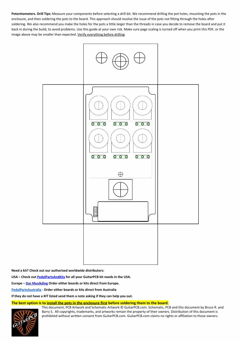
Potentiometers. Drill Tips: Measure your components before selecting a drill bit. We recommend drilling the pot holes, mounting the pots in the
enclosure, and then soldering the pots to the board. This approach should resolve the issue of the pots not fitting through the holes after
soldering. We also recommend you make the holes for the pots a little larger than the threads in case you decide to remove the board and put it
back in during the build, to avoid problems. Use this guide at your own risk. Make sure page scaling is turned off when you print this PDF, or the
image above may be smaller than expected. Verify everything before drilling.
Need a kit? Check out our authorized worldwide distributors:
USA – Check out PedalPartsAndKits for all your GuitarPCB kit needs in the USA.
Europe – Das Musikding Order either boards or kits direct from Europe.
PedalPartsAustralia - Order either boards or kits direct from Australia
If they do not have a KIT listed send them a note asking if they can help you out.
The best option is to install the pots in the enclosure first before soldering them to the board. This document, PCB Artwork and Schematic Artwork © GuitarPCB.com. Schematic, PCB and this document by Bruce R. and Barry S. All copyrights, trademarks, and artworks remain the property of their owners. Distribution of this document is prohibited without written consent from GuitarPCB.com. GuitarPCB.com claims no rights or affiliation to those owners.