Tsubaki Drive Chains & Sprockets
210
TSUBAKI DRIVE CHAINS & SPROCKETS
Transcript of Tsubaki Drive Chains & Sprockets

TSUBAKIDRIVE CHAINS &SPROCKETS

ISO 9001 ISO 14001
Kyotanabe Plant Concepts
Kind consideration towards the global environment
Harmony and coexistence with the global environment
Pursuit of high efficiency and high quality
Courage to look to the future
Tsubakimoto Chain's Kyotanabe Plant is a state-of-the-art facility outfitted with the latest environmental systems to produce environment-friendly products that meet the needs of the times and our customers.
Tsubakimoto Chain aims to make products that are people-friendly, environmentally friendly, and reliable. Tsubakimoto Chain acquired ISO9001 accreditation in 1995 and ISO14001 accreditation in 2003.
Philosophy
Policy
1
Tsubaki’s pursuit of outstanding quality drives the world.Since its founding, Tsubaki has pursued the world’s most outstanding quality while contributing to a better society. And Tsubaki will continue providing the world with only the best.

2
Reduce your maintenance times, improve your work environment, and increase your productivity.
Super Roller ChainRS-HT ChainSuper H Roller ChainUltra Super Roller Chain
Provides higher kilowatt ratings, allowable loads, and greater tensile strength than RS Roller Chain, allowing users to go 1 – 2 sizes down.
Provide resistance to a variety of operating environments.
RS® Curved Roller ChainLeaf Chain
Chains designed for special applications.
3
Before Use
Notes on Using Roller ChainGeneral Comparison of Transmission ElementsFeatures and Precautions of Roller Chain Transmission
……………………Pg. 7……Pg. 8
……………………Pg. 8
Roller Chain Construction Pg. 11
Roller Chain Product Line-up Pg. 13
Glossary Pg. 9
Pg. 7
Pg. 190
New Products Pg. 5
Ordering RS Roller Chain Pg. 15
Pg. 206
Pg. 162Roller Chain Selection
1. Selection Guide2. Service Factors3. Provisional Selection Graph4. Selection Formulae5. General Selection6. Allowable Load Selection7. Example of Lifting Transmissions8. Calculating Moment of Inertia9. Example of Shuttle Traction10.Pin Gear Drive Selection11.Temperature Selection12.Special Selection Method for Corrosion Resistant Roller Chain13.Corrosion Resistance Reference Guide for Corrosion Resistant Drive Chains and Sprockets
……………………………… Pg. 163……………………………… Pg. 165
…………… Pg. 166………………………… Pg. 168………………………… Pg. 171
……………… Pg. 173…… Pg. 178
………… Pg. 180…………… Pg. 181
………………… Pg. 182…………………… Pg. 188
… Pg. 188
…Pg. 189
Handling Roller Chains and Sprockets
1. How to Cut Roller Chain2. How to Connect Roller Chain3. Roller Chain Lubrication4. Layout and Installation5. Sprockets6. Chain Test Run7. Roller Chain Inspection8. Cautions on Use in Special Environments9. Troubleshooting
………………… Pg. 190………… Pg. 191
………………… Pg. 192…………………… Pg. 194
……………………………………… Pg. 196……………………………… Pg. 197
…………………… Pg. 197… Pg. 201
……………………………… Pg. 202
Roller Chain Inquiry Sheet
Eco Link MarkThese products meet Tsubaki’s voluntary eco assessment criteria.
Pg. 18
Pg. 53
Pg. 69
Pg. 78
Pg. 91
Standard Roller Chain
Lube Free Roller Chains
Heavy Duty Roller Chains
Corrosion Resistant Roller Chains
Specialty Roller Chains
…………Pg. 18
…………Pg. 49
………Pg. 71………………Pg. 74
……Pg. 77…Pg. 78
…Pg. 81
…Pg. 84
…………Pg. 87
………Pg. 87
………Pg. 88………………Pg. 90
………Pg. 90
…Pg. 91…………………Pg. 92
……………Pg. 57…Pg. 58
…………Pg. 59…Pg. 60…Pg. 63…Pg. 65…Pg. 66
Index
Trust Tsubaki’s Robust Line-up to Increase Your Productivity

4
Pg. 134Easy Bore Finishing Service
Pg. 139Sprocket Engineering Information
Pg. 208For Safe Use
Pg. 98
Pg. 142
Pg. 152
Pg. 101
Pg. 108
Pg. 122
Pg. 133
RS® Sprocket Standard Pilot Bore Series
Fit Bore Series
Lock Series
Corrosion Resistant Series
Specialty Sprockets
Accessories (Peripheral Instruments)
Pin Gear Drives
Wide selection of standard sprockets for general use RS Roller Chain.
……Pg. 17,Pg. 98…Pg. 99…Pg. 100
…………Pg. 133
Each model is provided with a finished bore, keyway, and set screws.
……………………Pg. 101
Peripheral instruments for your chain maintenance needs.
………Pg. 153……Pg. 157…Pg. 158
………………Pg. 159…Pg. 160…Pg. 161
Pin gear drives use Tsubaki’s long experience in creating drive units to provide increased performance, easier mounting, and a greater operating range. (Linear and rotating drive types available.)
………Pg. 142
…Pg. 145
RS standard sprockets can be mounted to shafts without using keys.
……Pg. 109……Pg. 120
Sprockets made of excellent corrosion-resistant stainless steel, and sprockets made of engineering plastic that can be used without lubrication.
…Pg. 122
……Pg. 127
Sprockets for special applications, such as torque limiter sprockets.
…Pg. 133
Index
BS/DIN RS® Roller Chain GT4 Winner
5
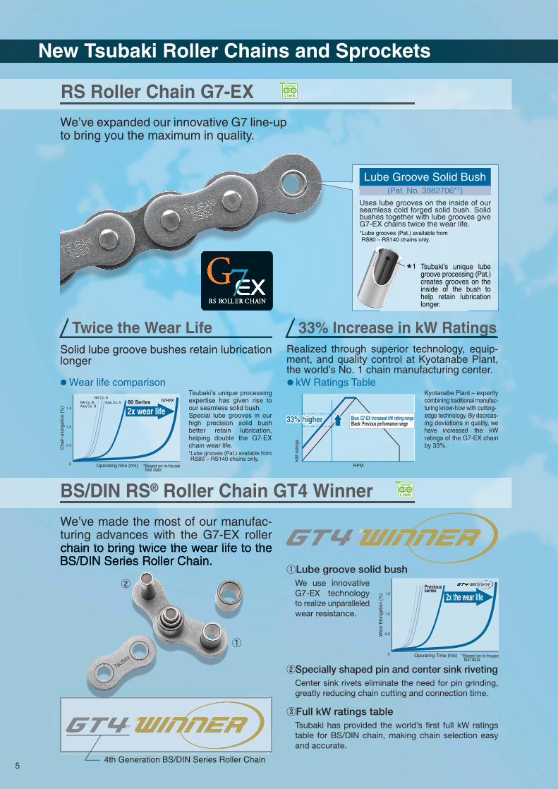
Twice the Wear Life 33% Increase in kW Ratings
Tsubaki’s unique processing expertise has given rise to our seamless solid bush.Special lube grooves in our high precision solid bush better retain lubrication, helping double the G7-EX chain wear life.
We use innovative G7-EX technology to realize unparalleled wear resistance.
Kyotanabe Plant – expertly combining traditional manufac-turing know-how with cutting-edge technology. By decreas-ing deviations in quality, we have increased the kW ratings of the G7-EX chain by 33%.
We’ve made the most of our manufac-turing advances with the G7-EX roller chain to bring twice the wear life to the BS/DIN Series Roller Chain.
We’ve expanded our innovative G7 line-up to bring you the maximum in quality.
①Lube groove solid bush
Center sink rivets eliminate the need for pin grinding, greatly reducing chain cutting and connection time.
②Specially shaped pin and center sink riveting
Tsubaki has provided the world’s first full kW ratings table for BS/DIN chain, making chain selection easy and accurate.
③Full kW ratings table
● kW Ratings Table● Wear life comparison
Previousseries
①
②
New Tsubaki Roller Chains and Sprockets
RS Roller Chain G7-EX
Solid lube groove bushes retain lubrication longer
Realized through superior technology, equip-ment, and quality control at Kyotanabe Plant, the world’s No. 1 chain manufacturing center.
Cha
in e
long
atio
n (%
)
NA Co. BAsia Co. B
NA Co. AAsia Co. A 80 Series
2x wear life
Operating time (hrs) *Based on in-house test data
*Lube grooves (Pat.) available from RS80 – RS140 chains only.
Lube Groove Solid Bush(Pat. No. 3982706*1)
Uses lube grooves on the inside of our seamless cold forged solid bush. Solid bushes together with lube grooves give G7-EX chains twice the wear life.*Lube grooves (Pat.) available from RS80 – RS140 chains only.
*1 Tsubaki’s unique lube groove processing (Pat.) creates grooves on the inside of the bush to help retain lubrication longer.
33% higher33% higher33% higher
kW r
atin
gs
RPM
Blue: G7-EX increased kW rating rangeBlack: Previous performance range
4th Generation BS/DIN Series Roller Chain
Wea
r E
long
atio
n (%
) 2x the wear life
Operating Time (hrs) *Based on in-house test data
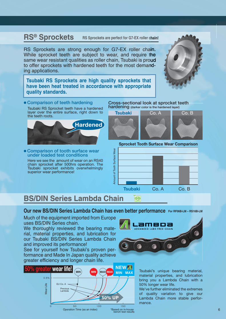
BS/DIN Series Lambda Chain
6
Our new BS/DIN Series Lambda Chain has even better performanceMuch of the equipment imported from Europe uses BS/DIN Series chain.We thoroughly reviewed the bearing mate-rial, material properties, and lubrication for our Tsubaki BS/DIN Series Lambda Chain and improved its performance!See for yourself how Tsubaki’s proven per-formance and Made In Japan quality achieve greater efficiency and longer chain life.
RS® Sprockets
RS Sprockets are strong enough for G7-EX roller chain. While sprocket teeth are subject to wear, and require the same wear resistant qualities as roller chain, Tsubaki is proud to offer sprockets with hardened teeth for the most demand-ing applications.
Tsubaki RS Sprocket teeth have a hardened layer over the entire surface, right down to the teeth roots.
● Comparison of teeth hardening
Here we see the amount of wear on an RS40 chain sprocket after 500hrs operation. The Tsubaki sprocket exhibits overwhelmingly superior wear performance!
● Comparison of tooth surface wear under loaded test conditions
RS Sprockets are perfect for G7-EX roller chain!
Tsubaki RS Sprockets are high quality sprockets that have been heat treated in accordance with appropriate quality standards.
Tsubaki
Tsubaki Co. A Co. B
Co. A Co. B
*Based on in-house bench test results
0 50
0.5%
100 150Operation Time (as an index)
NEWMIN MIN MAXMAX MAXMIN
For RF06B-LM – RS16B-LM
Tsubaki’s unique bearing material, material properties, and lubrication bring you a Lambda Chain with a 50% longer wear life.We’ve further eliminated the extremes of quality variation to give our Lambda Chain more stable perfor-mance.
50% UP
33% higher
Hardened
Cross-sectional look at sprocket teeth hardening (darker color is the hardened layer)
Sprocket Tooth Surface Wear Comparison
Am
ount
of T
ooth
Sur
face
Wea
r
50% greater wear life!
Wea
r Li
fe EU Co. A
Previous Lambda

7
With the exception of endless chains, the transmission power tables in this catalog are based on use with connecting parts (connecting links or offset links).See page 12 for details on connecting parts.
This drive chain catalog explains how to select, install and maintain all listed Tsubaki Roller Chains. Numerical figures are indicated in both SI and gravimetric units. Read through this catalog before use to ensure proper selection and usage. Also, carefully inform persons involved in installation and maintenance of all pertinent matters.
NOTE
NOTE
Ordinary Transmission
Shuttle Traction
When using a roller chain in lifting applications, keep clear from underneath the load.If there is the possibility of serious accident or death in the event of roller chain breakage during lifting or other applications, install reliable safety devices to prevent accidents.Inspect and replace worn roller chain periodically.Roller chains can break and climb up on the sprocket from wear elongation. (Lubrication can extend service life against wear elongation. Tsubaki also offers lube-free drive chains that deliver long-lasting service without lubrication.)Overload may cause roller chain to break. (Avoid breakage by properly selecting products with consideration of inertia, etc. Tsubaki offers heavy-duty drive chains in identical sizes that deliver the high strength of larger chains.) Roller chains can break due to corrosion and other environmental conditions. (Avoid breakage by preventing exposure to corrosive liquids, atmospheres, etc. Tsubaki offers excellent corrosion-resistant drive chains.)Correctly install roller chain to avoid misalignment or uneven wear and possible breakage.
Pin Gear Drive
Lifting Applications
Drum
Pin gearsprocket
Pin gear attachment chain
Before Use
Notes on Using Roller Chains
Befo
re Use
Standard R
oller Chains
Lube-Free Roller C
hainsH
eavy Duty R
oller Chains
Corrosion Resistant Roller ChainsS
pecialty Roller C
hainsS
pro
cketsP
in G
ear Drives
Accesso
riesS
election
Han
dlin
g
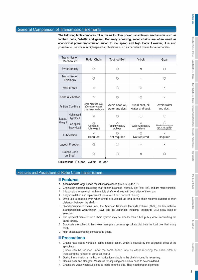
Accommodate large speed reductions/increases (usually up to 1:7).Chains can accommodate long shaft center distances (normally less than 4 m), and are more versatile.It is possible to use chain with multiple shafts or drives with both sides of the chain.Easy installation and replacement (easy to cut and connect chains).Drive use is possible even when shafts are vertical, as long as the chain receives support in short distances between the shafts.Standardization of chains under the American National Standards Institute (ANSI), the International Standardization Organization (ISO), and the Japanese Industrial Standards (JIS) allow ease of selection.The sprocket diameter for a chain system may be smaller than a belt pulley while transmitting the same torque.Sprockets are subject to less wear than gears because sprockets distribute the load over their many teeth.High shock absorbency compared to gears.
Chains have speed variation, called chordal action, which is caused by the polygonal effect of the sprockets.(Shock can be reduced under the same speed ratio by either reducing the chain pitch or increasing the number of sprocket teeth.)During transmission, a method of lubrication suitable to the chain's speed is necessary.Chains wear and elongate. Measures for adjusting chain slack need to be considered.Chains are weak when subjected to loads from the side. They need proper alignment.
8
The following table compares roller chains to other power transmission mechanisms such as toothed belts, V-belts and gears. Generally speaking, roller chains are often used as economical power transmission suited to low speed and high loads. However, it is also possible to use chain in high-speed applications such as camshaft drives for automobiles.
TransmissionMechanism
Synchronicity ◎
TransmissionEfficiency ◎
Anti-shock ×
Noise & Vibration ×
Ambient Conditions
High speed,light load
Low speed,heavy load
Space,Weight
◯
◯
Lubrication
Layout Freedom
Excess Loadon Shaft
×Required
×
◎
Roller Chain
Avoid water and dust.(Corrosion-resistant
drive chains available.)
Compact,lightweight
Slightly heavypulleys
Wide with heavypulleys
Avoid heat, oil,water and dust.
Avoid heat, oil,water and dust.
Needs high strengthdue to low numberof engaging teeth.
Avoid waterand dust.
◎ ◎ ×
◎ ◎ △
△ ◯ ◎
△ ◎ ◎
× ◎ ◯
◎ △ ×
×Required
◎Not required
◎Not required
◎ ◯ △
◎ ◯ ×
◎Excellent ◯Good △Fair ×Poor
Toothed Belt V-belt Gear
1.2.3.4.5.
6.
7.
8.
9.
1.
2.3.4.
Features
Precautions
Features and Precautions of Roller Chain Transmissions
General Comparison of Transmission Elements
Befo
re Use
Standard R
oller Chains
Lube-Free Roller C
hainsH
eavy Duty R
oller Chains
Corrosion Resistant Roller ChainsS
pecialty Roller C
hainsS
pro
cketsP
in G
ear Drives
Accesso
riesS
election
Han
dlin
g
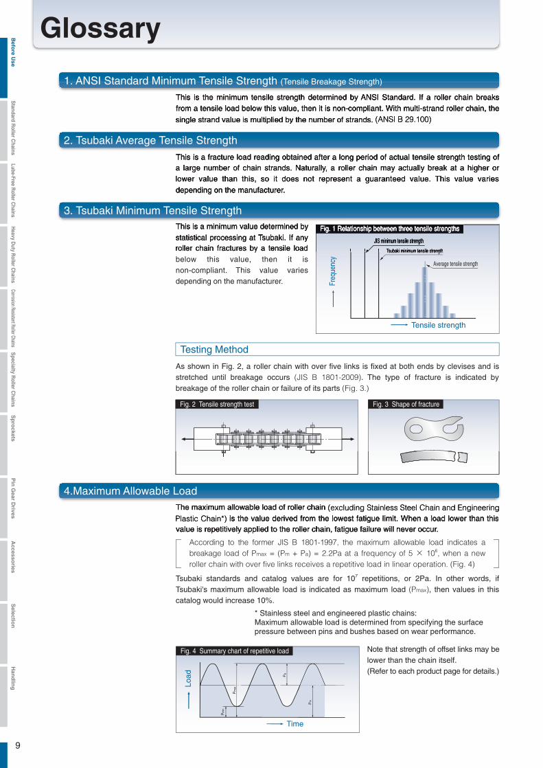
Fig. 4 Summary chart of repetitive load
9
This is the minimum tensile strength determined by ANSI Standard. If a roller chain breaks from a tensile load below this value, then it is non-compliant. With multi-strand roller chain, the single strand value is multiplied by the number of strands. (ANSI B 29.100)
This is a fracture load reading obtained after a long period of actual tensile strength testing of a large number of chain strands. Naturally, a roller chain may actually break at a higher or lower value than this, so it does not represent a guaranteed value. This value varies depending on the manufacturer.
As shown in Fig. 2, a roller chain with over five links is fixed at both ends by clevises and is stretched until breakage occurs (JIS B 1801-2009). The type of fracture is indicated by breakage of the roller chain or failure of its parts (Fig. 3.)
This is a minimum value determined by statistical processing at Tsubaki. If any roller chain fractures by a tensile load below this value, then it is non-compliant. This value varies depending on the manufacturer.
Note that strength of offset links may be lower than the chain itself.(Refer to each product page for details.)
The maximum allowable load of roller chain (excluding Stainless Steel Chain and Engineering Plastic Chain*) is the value derived from the lowest fatigue limit. When a load lower than this value is repetitively applied to the roller chain, fatigue failure will never occur.
Tsubaki standards and catalog values are for 107 repetitions, or 2Pa. In other words, if Tsubaki's maximum allowable load is indicated as maximum load (Pmax), then values in this catalog would increase 10%.
According to the former JIS B 1801-1997, the maximum allowable load indicates a breakage load of Pmax = (Pm + Pa) = 2.2Pa at a frequency of 5 × 10⁶, when a new roller chain with over five links receives a repetitive load in linear operation. (Fig. 4)
Tsubaki minimum tensile strength
Average tensile strength
JIS minimum tensile strength
Fig. 1 Relationship between three tensile strengths
Fig. 2 Tensile strength test Fig. 3 Shape of fracture
* Stainless steel and engineered plastic chains: Maximum allowable load is determined from specifying the surfacepressure between pins and bushes based on wear performance.
Freq
uenc
yTensile strength
Time
Load
Testing Method
Glossary
1. ANSI Standard Minimum Tensile Strength (Tensile Breakage Strength)
2. Tsubaki Average Tensile Strength
3. Tsubaki Minimum Tensile Strength
4.Maximum Allowable Load
Befo
re Use
Standard R
oller Chains
Lube-Free Roller C
hainsH
eavy Duty R
oller Chains
Corrosion Resistant Roller ChainsS
pecialty Roller C
hainsS
pro
cketsP
in G
ear Drives
Accesso
riesS
election
Han
dlin
g
10
RS Roller Chain, SUPER Roller Chain, Heavy Duty Chain, and Low Noise Drive Chain kilowatt ratings tables show kW values for 15,000 hours of operation using a two-shaft drive and 100 pitches of roller chain under conditions 1 - 5 below.The kW ratings table of Lambda Chain is based on conditions 1 - 4 and shows kW rating values when Lambda Chain is used with two shafts. Lambda Chain has more than seven times the wear elongation of Standard RS Roller Chain operated without lubrication (#120 and #140 are over 2.5 times). X-LAMBDA has more than five times the wear elongation life of Lambda Roller Chain.
1)
2)
3)
4)
5)
The chains are operated under ordinary conditions where the ambient temperature is -10℃ - +60℃
(+14°F to +140°F) and there is no abrasive dust.
There are no negative effects from corrosive gasses or high humidity.
The two shafts are level and the chains are properly installed. (See item 4 on pg. 194.)There is minimal fluctuation in load during transmission.
The recommended lubrication system and lubricant shown in the kW ratings tables is used for RS Roller
Chain and Super Roller Chain. (See pgs. 192 - 193.)
6. Moment of Inertia (I / J / GD2)
7. Total Length Tolerance of Roller Chain
8. Elastic Elongation of Chain under Load
Length test method and length tolerance are specified in JIS B 1801-2009. The length tolerance of any individual size when subjected to a measured load (e.g. 500 N [50.99 kgf] for RS 80) specified in JIS is 0 to +0.15% of the reference length. The reference length is calculated by multiplying the reference pitch (P) by the number of links. (Applicable to products bearing a JIS identification number.)
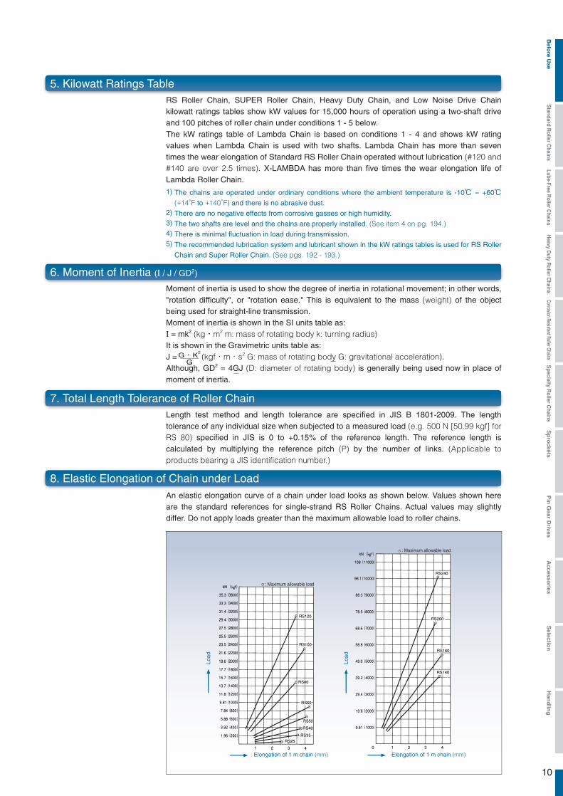
An elastic elongation curve of a chain under load looks as shown below. Values shown here are the standard references for single-strand RS Roller Chains. Actual values may slightly differ. Do not apply loads greater than the maximum allowable load to roller chains.
Load
Elongation of 1 m chain (mm)
: Maximum allowable load
Load
Elongation of 1 m chain (mm)
: Maximum allowable load
5. Kilowatt Ratings Table
Moment of inertia is used to show the degree of inertia in rotational movement; in other words, "rotation difficulty", or "rotation ease." This is equivalent to the mass (weight) of the object being used for straight-line transmission.Moment of inertia is shown in the SI units table as:I = mk2 (kg・m2 m: mass of rotating body k: turning radius)It is shown in the Gravimetric units table as:J = (kgf・m・s2 G: mass of rotating body G: gravitational acceleration).Although, GD2 = 4GJ (D: diameter of rotating body) is generally being used now in place of moment of inertia.
G・K2
G
Befo
re Use
Standard R
oller Chains
Lube-Free Roller C
hainsH
eavy Duty R
oller Chains
Corrosion Resistant Roller ChainsS
pecialty Roller C
hainsS
pro
cketsP
in G
ear Drives
Accesso
riesS
election
Han
dlin
g
11
Roller Chain Construction
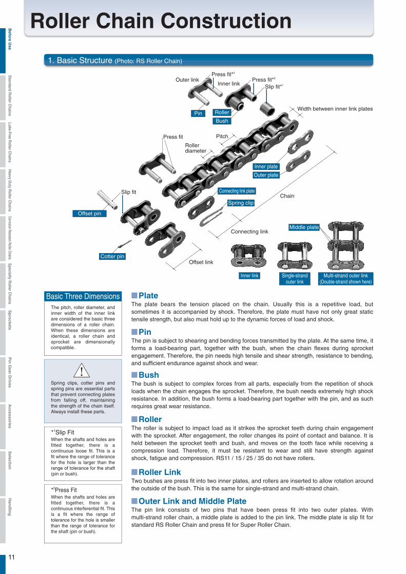
1. Basic Structure (Photo: RS Roller Chain)
The plate bears the tension placed on the chain. Usually this is a repetitive load, but sometimes it is accompanied by shock. Therefore, the plate must have not only great static tensile strength, but also must hold up to the dynamic forces of load and shock.
The pitch, roller diameter, and inner width of the inner link are considered the basic three dimensions of a roller chain. When these dimensions are identical, a roller chain and sprocket are dimensionally compatible.
Basic Three Dimensions
When the shafts and holes are fitted together, there is a continuous loose fit. This is a fit where the range of tolerance for the hole is larger than the range of tolerance for the shaft (pin or bush).
*1Slip Fit
When the shafts and holes are fitted together, there is a continuous interferential fit. This is a fit where the range of tolerance for the hole is smaller than the range of tolerance for the shaft (pin or bush).
*2Press Fit
Spring clips, cotter pins and spring pins are essential parts that prevent connecting plates from falling off, maintaining the strength of the chain itself. Always install these parts.
The pin is subject to shearing and bending forces transmitted by the plate. At the same time, it forms a load-bearing part, together with the bush, when the chain flexes during sprocket engagement. Therefore, the pin needs high tensile and shear strength, resistance to bending, and sufficient endurance against shock and wear.
The bush is subject to complex forces from all parts, especially from the repetition of shock loads when the chain engages the sprocket. Therefore, the bush needs extremely high shock resistance. In addition, the bush forms a load-bearing part together with the pin, and as such requires great wear resistance.
The roller is subject to impact load as it strikes the sprocket teeth during chain engagement with the sprocket. After engagement, the roller changes its point of contact and balance. It is held between the sprocket teeth and bush, and moves on the tooth face while receiving a compression load. Therefore, it must be resistant to wear and still have strength against shock, fatigue and compression. RS11 / 15 / 25 / 35 do not have rollers.
Two bushes are press fit into two inner plates, and rollers are inserted to allow rotation around the outside of the bush. This is the same for single-strand and multi-strand chain.
The pin link consists of two pins that have been press fit into two outer plates. With multi-strand roller chain, a middle plate is added to the pin link. The middle plate is slip fit for standard RS Roller Chain and press fit for Super Roller Chain.
Chain
Rollerdiameter
Pitch
Width between inner link plates
Inner linkOuter link
Slip fit
Connecting link
Offset linkCotter pin
Offset pin
Slip fit*1
Press fit
Press fit*2
Press fit*2
Pin Roller
Bush
Connecting link plate
Inner plate
Outer plate
Middle plate
Spring clip
Inner link Single-strandouter link
Multi-strand outer link(Double-strand shown here)
!
Plate
Pin
Bush
Roller
Roller Link
Outer Link and Middle Plate
Befo
re Use
Standard R
oller Chains
Lube-Free Roller C
hainsH
eavy Duty R
oller Chains
Corrosion Resistant Roller ChainsS
pecialty Roller C
hainsS
pro
cketsP
in G
ear Drives
Accesso
riesS
election
Han
dlin
g
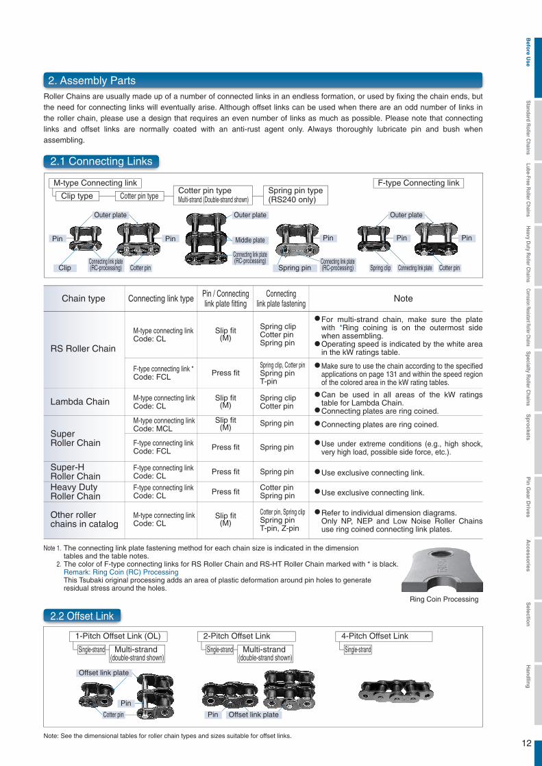
2.1 Connecting Links
12
Roller Chains are usually made up of a number of connected links in an endless formation, or used by fixing the chain ends, but the need for connecting links will eventually arise. Although offset links can be used when there are an odd number of links in the roller chain, please use a design that requires an even number of links as much as possible. Please note that connecting links and offset links are normally coated with an anti-rust agent only. Always thoroughly lubricate pin and bush when assembling.
M-type Connecting link F-type Connecting link
Clip type Cotter pin typeCotter pin typeMulti-strand (Double-strand shown)
Spring pin type(RS240 only)
Outer plate
Connecting link plate(RC-processing)
Connecting link plate(RC-processing) Connecting link plate
(RC-processing)
Outer plate
Middle plate
Connecting link plate
Pin Pin Pin Pin Pin
Cotter pin Cotter pinClip Spring clipSpring pin
Outer plate
1-Pitch Offset Link (OL)
Single-strand Multi-strand (double-strand shown)
Single-strand Multi-strand (double-strand shown)
2-Pitch Offset Link
Single-strand
4-Pitch Offset Link
Chain type Connecting link type NotePin / Connectinglink plate fitting
Connectinglink plate fastening
M-type connecting linkCode: CL
Spring clipCotter pinSpring pin
Slip fit(M)
Cotter pin, Spring clipSpring pinT-pin, Z-pin
F-type connecting link *Code: FCL
F-type connecting linkCode: FCL
Spring clip, Cotter pinSpring pinT-pin
Press fit
F-type connecting linkCode: CL
M-type connecting linkCode: CL
M-type connecting linkCode: MCL
M-type connecting linkCode: CL
Spring clipCotter pin
Spring pin
Slip fit(M)
Cotter pinSpring pin
Slip fit(M)
Slip fit(M)
Spring pinPress fit
Spring pinPress fit
F-type connecting linkCode: CL Press fit
RS Roller Chain
Lambda Chain
Super-HRoller ChainHeavy DutyRoller Chain
Other rollerchains in catalog
SuperRoller Chain
2.2 Offset Link
For multi-strand chain, make sure the plate with *Ring coining is on the outermost side when assembling.Operating speed is indicated by the white area in the kW ratings table.
Can be used in all areas of the kW ratings table for Lambda Chain.Connecting plates are ring coined.
Use under extreme conditions (e.g., high shock, very high load, possible side force, etc.).
Use exclusive connecting link.
Use exclusive connecting link.
Refer to individual dimension diagrams.Only NP, NEP and Low Noise Roller Chains use ring coined connecting link plates.
Connecting plates are ring coined.
Make sure to use the chain according to the specified applications on page 131 and within the speed region of the colored area in the kW rating tables.
Note 1.
2.
The connecting link plate fastening method for each chain size is indicated in the dimensiontables and the table notes.The color of F-type connecting links for RS Roller Chain and RS-HT Roller Chain marked with * is black.Remark: Ring Coin (RC) ProcessingThis Tsubaki original processing adds an area of plastic deformation around pin holes to generateresidual stress around the holes.
2. Assembly Parts
Note: See the dimensional tables for roller chain types and sizes suitable for offset links.
Pin
Offset link plate
Cotter pin Pin Offset link plate
Ring Coin Processing
Befo
re Use
Standard R
oller Chains
Lube-Free Roller C
hainsH
eavy Duty R
oller Chains
Corrosion Resistant Roller ChainsS
pecialty Roller C
hainsS
pro
cketsP
in G
ear Drives
Accesso
riesS
election
Han
dlin
g
13
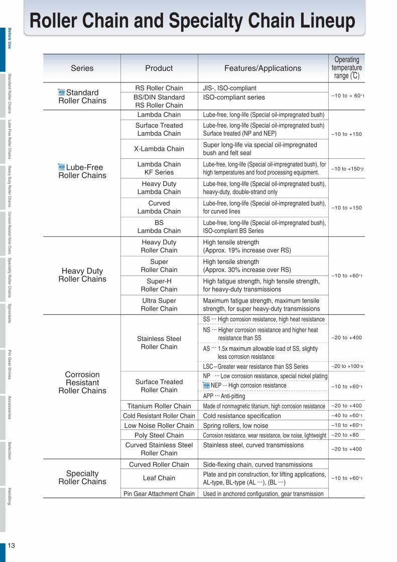
Roller Chain and Specialty Chain Lineup
Series
StandardRoller Chains
RS Roller Chain JIS-, ISO-compliant–10 to + 60*1BS/DIN Standard
RS Roller ChainISO-compliant series
Product Features/ApplicationsOperating
temperaturerange (℃)
Lube-FreeRoller Chains
Lambda Chain Lube-free, long-life (Special oil-impregnated bush)
–10 to +150
–10 to +150*2
–10 to +150
X-Lambda Chain
Lube-free, long-life (Special oil-impregnated bush) Surface treated (NP and NEP)
Curved Roller Chain Side-flexing chain, curved transmissions
Used in anchored configuration, gear transmission
Leaf Chain
Pin Gear Attachment Chain
Plate and pin construction, for lifting applications, AL-type, BL-type (AL ), (BL )
Surface TreatedLambda Chain
Super long-life via special oil-impregnated bush and felt seal
Lambda ChainKF Series
Lube-free, long-life (Special oil-impregnated bush), for high temperatures and food processing equipment.
Heavy DutyLambda Chain
Lube-free, long-life (Special oil-impregnated bush), heavy-duty, double-strand only
CurvedLambda Chain
Lube-free, long-life (Special oil-impregnated bush), for curved lines
BSLambda Chain
Lube-free, long-life (Special oil-impregnated bush), ISO-compliant BS Series
Heavy DutyRoller Chains
Heavy DutyRoller Chain
High tensile strength (Approx. 19% increase over RS)
SuperRoller Chain
High tensile strength (Approx. 30% increase over RS)
Super-HRoller Chain
High fatigue strength, high tensile strength, for heavy-duty transmissions
–10 to +60*1
Ultra SuperRoller Chain
Maximum fatigue strength, maximum tensile strength, for super heavy-duty transmissions
CorrosionResistant
Roller Chains
SpecialtyRoller Chains
Surface TreatedRoller Chain
SS High corrosion resistance, high heat resistance
NS Higher corrosion resistance and higher heat resistance than SS
AS 1.5x maximum allowable load of SS, slightly less corrosion resistance
LSC Greater wear resistance than SS Series
–20 to +400
–20 to +100*4
–20 to +400Titanium Roller Chain Made of nonmagnetic titanium, high corrosion resistance
Cold Resistant Roller Chain Cold resistance specification –40 to +60*1
Low Noise Roller Chain Spring rollers, low noise –10 to +60*1
Poly Steel Chain Corrosion resistance, wear resistance, low noise, lightweight –20 to +80
Curved Stainless SteelRoller Chain
–20 to +400Stainless steel, curved transmissions
Stainless SteelRoller Chain
NP Low corrosion resistance, special nickel plating NEP High corrosion resistance
APP Anti-pitting
–10 to +60*1
–10 to +60*1
Befo
re Use
Standard R
oller Chains
Lube-Free Roller C
hainsH
eavy Duty R
oller Chains
Corrosion Resistant Roller ChainsS
pecialty Roller C
hainsS
pro
cketsP
in G
ear Drives
Accesso
riesS
election
Han
dlin
g

RS48B
●● ● ● ● ● ● ● ● ● ●
*1: The operating temperature range of pre-lubricated chains (those coated with oil when delivered) is -10 to +60℃℃ (-40 to +60℃ for KT specification). Chain kW ratings do not decrease until 150℃. To use in +60 to 150℃ environments, apply a high temperature lubrication. For details and precautions in usage, see "Temperature Selection Method" (page 188) and "Roller Chain Lubrication" (page 192).
*2. Lambda Chain KF Series gives better lubrication performance in high temperature ranges (from ambient temperatures to ~230℃. When using in the 150℃ - 230℃ range, refer to pg. 188 for temperature selection methods.
*3. RS11-SS-1 comes lubricated.*4. Operating temperature range when using stainless steel rollers. Operating temperature range for plastic rollers is -20℃ to 80℃.*5: Sizes marked with are standard products shown in this catalog. For details, see the corresponding section. Blank cells are specialty items and may be
specially ordered. Contact a Tsubaki representative for details.*6: RS05B (pitch 8.00) and RS56B (pitch 88.9) are also available.
14
Chain No. (Pitch: mm) *2
11(3.7465)
Ref. page
15
55
69
79
91
15(4.7625)
25(6.35)
35(9.525)
40(12.70)
50(15.875)
60(19.05)
80(25.40)
100(31.75)
120(38.10)
140(44.45)
160(50.80)
180(57.15)
200(63.50)
240(76.20)
RF06B RS08B RS10B RS12B RS16B RS20B RS24B RS28B RS32B RS40B
● ● ● ● ● ● ● ● ● ● ● ● ● ●
● ● ●● ● ● ● ● ● ● ● ● ● ●
● ● ● ● ● ● ● ●
●● ● ● ● ● ● ● ●
●● ● ● ● ● ● ● ●
● ● ● ● ● ● ● ●
● ● ● ● ● ● ● ● ● ●
●
● ● ● ●
● ● ●● ●
● ● ● ●
● ● ● ●
● ●● ● ● ● ● ●
● ●● ● ● ●
●●
● ● ● ●
● ● ● ●
● ● ● ● ● ● ● ●
● ● ● ● ● ● ●
● ● ● ● ● ● ●
● ● ● ● ● ●
● ● ● ● ● ● ●
● ● ● ● ● ●
● ● ● ●
●● ● ● ● ● ●
● ● ● ● ●
● ● ●
RF06B RS08B RS10B RS12B RS16B RS20B RS24B RS28B RS32B RS40B
4 5 6 8 10 12 14 16
●● ● ● ● ● ●
*6 *6
Eco Link MarkThese new products meet our voluntary eco assessment criteria.
Befo
re Use
Standard R
oller Chains
Lube-Free Roller C
hainsH
eavy Duty R
oller Chains
Corrosion Resistant Roller ChainsS
pecialty Roller C
hainsS
pro
cketsP
in G
ear Drives
Accesso
riesS
election
Han
dlin
g
15
Product code Chainnumber
UnitsCount
Product code Chainnumber
UnitsCount
Product code UnitsCount
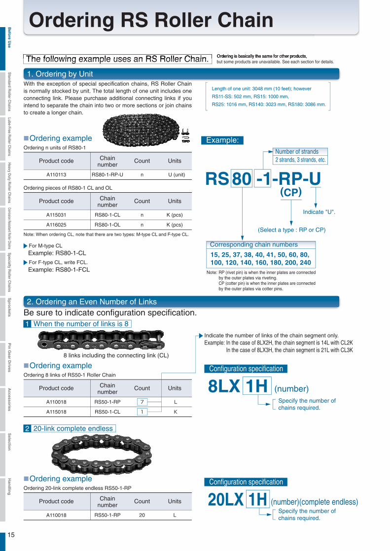
1. Ordering by Unit
2. Ordering an Even Number of Links
With the exception of special specification chains, RS Roller Chain is normally stocked by unit. The total length of one unit includes one connecting link. Please purchase additional connecting links if you intend to separate the chain into two or more sections or join chains to create a longer chain.
A110113 RS80-1-RP-U n U (unit)
A110018 RS50-1-RP
Ordering pieces of RS80-1 CL and OL
A115031 RS80-1-CL
Example: RS80-1-CL
n
A116025 RS80-1-OL n
K (pcs)
K (pcs)
A115018 RS50-1-CL 1
L
K
Product code Chainnumber
UnitsCount
A110018 RS50-1-RP L20
For F-type CL, write FCL.
Example: RS80-1-FCL
Configuration specification
RS 80 -1-RP-U(CP)
8LX 1H
Corresponding chain numbers
15, 25, 37, 38, 40, 41, 50, 60, 80, 100, 120, 140, 160, 180, 200, 240
Specify the number of chains required.
Specify the number of chains required.
20LX 1H (number)(complete endless)
1 When the number of links is 8
2 20-link complete endless
Number of strands2 strands, 3 strands, etc.
(Select a type : RP or CP)
Indicate "U".
7
(number)
Ordering is basically the same for other products, but some products are unavailable. See each section for details.The following example uses an RS Roller Chain.
Ordering exampleOrdering n units of RS80-1
Ordering exampleOrdering 8 links of RS50-1 Roller Chain
Ordering exampleOrdering 20-link complete endless RS50-1-RP
For M-type CL
Be sure to indicate configuration specification.
Length of one unit: 3048 mm (10 feet); however
RS11-SS: 502 mm, RS15: 1000 mm,
RS25: 1016 mm, RS140: 3023 mm, RS180: 3086 mm.
Chainnumber
Example:
Note: When ordering CL, note that there are two types: M-type CL and F-type CL.
Indicate the number of links of the chain segment only.Example: In the case of 8LX2H, the chain segment is 14L with CL2K
In the case of 8LX3H, the chain segment is 21L with CL3K8 links including the connecting link (CL)
Configuration specification
Note: RP (rivet pin) is when the inner plates are connectedby the outer plates via riveting.CP (cotter pin) is when the inner plates are connectedby the outer plates via cotter pins.
Ordering RS Roller ChainBefo
re Use
Standard R
oller Chains
Lube-Free Roller C
hainsH
eavy Duty R
oller Chains
Corrosion Resistant Roller ChainsS
pecialty Roller C
hainsS
pro
cketsP
in G
ear Drives
Accesso
riesS
election
Han
dlin
g
16
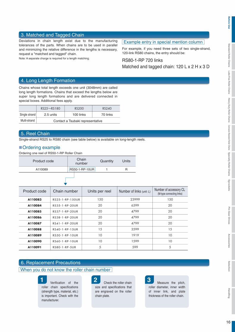
5. Reel Chain
6. Replacement Precautions
Single-strand RS25 to RS80 chain (see table below) is available on long-length reels.
For example, if you need three sets of two single-strand, 120-link RS80 chains, the entry should be:
3. Matched and Tagged ChainDeviations in chain length exist due to the manufacturing tolerances of the parts. When chains are to be used in parallel and minimizing the relative difference in the lengths is necessary, request a "matched and tagged" chain.Note: A separate charge is required for a length matching.
Chains whose total length exceeds one unit (3048mm) are called long length formations. Chains that exceed the lengths below are super long length formations and are delivered connected in special boxes. Additional fees apply.
4. Long Length Formation
Chain number Units per reel Number of links (unit: L) Number of accessory CL (M-type connecting links)
RS25-1-RP-150UR 23999 150
RS35-1-RP-20UR 6399 20
RS37-1-RP-20UR 4799
RS38-1-RP-20UR 4799
RS41-1-RP-20UR 4799
RS40-1-RP-15UR 3599
RS50-1-RP-10UR 1919
RS60-1-RP-10UR 1599
RS80-1-RP-5UR 599
150
20
20
20
20
15
10
10
5
20
20
20
15
10
10
5
When you do not know the roller chain number
1 2 3
A110089 1 RRS50-1-RP-10UR
Example entry in special mention column
RS80-1-RP 720 linksMatched and tagged chain: 120 L x 2 H x 3 D
Product code UnitsQuantity
Ordering exampleOrdering one reel of RS50-1-RP Roller Chain
Chainnumber
Verification of the roller chain specifications (strength type, material, etc.) is important. Check with the manufacturer.
Check the roller chain size and specifications that are engraved on the roller chain plate.
Measure the pitch, roller diameter, inner width of inner link, and plate thickness of the roller chain.
A110083
A110084
A110085
A110086
A110087
A110088
A110089
A110090
A110091
Product code
Single strand
Multi-strand
70 links
Contact a Tsubaki representative
2.5 units 100 links
Befo
re Use
Standard R
oller Chains
Lube-Free Roller C
hainsH
eavy Duty R
oller Chains
Corrosion Resistant Roller ChainsS
pecialty Roller C
hainsS
pro
cketsP
in G
ear Drives
Accesso
riesS
election
Han
dlin
g
17
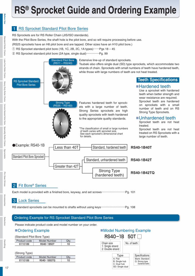
Please indicate product code and model number on your order.
■Ordering Example
■Hardened teeth
Product code Model Number Qty.
Product code Model Number Qty.
■Model Numbering Example
□
●Example: RS40-1B RS40-1B40T
RS40-1B42T
RS40-1B42TQ
0189 1B50T
RS40-1B 50T
1B50TQ0189
1 RS Sprocket Standard Pilot Bore Series
Each model is provided with a finished bore, keyway, and set screws……………………Pg. 101
2 Fit Bore® Series
RS standard sprockets can be mounted to shafts without using keys………………………Pg. 108
3 Lock Series
Teeth Specifications
Use a sprocket with hardened teeth when better strength and wear resistance are required.Sprocket teeth are hardened on sprockets with a small number of teeth and on RS Strong Type Sprockets.
■Unhardened teethSprocket teeth are not heat treated.Sprocket teeth are not heat treated on RS Sprockets with a large number of teeth.
RS® Sprocket Guide and Ordering Example
RS Sprockets are for RS Roller Chain (JIS/ISO standards).
With the Pilot Bore Series, the shaft hole is the pilot bore, and so will require processing before use.
(RS25 sprockets have an H8 pilot bore and are tapped. Other sizes have an H10 pilot bore.)
① RS Sprocket standard pilot bore (1B, 1C, 2B, 2C, 1A types)……Pgs 18 – 45
② RS Sprocket standard pilot bore (2A type, single dual)……………Pg. 99
RS Sprocket StandardPilot Bore Series
Standard Pilot Bore(RS11 – RS240)
Strong Type(RS35 – RS160)
Extensive line-up of standard sprockets.Tsubaki also offers single dual (SD) type sprockets, which accommodate two strands of chain. Sprockets with small numbers of teeth have hardened teeth, while those with large numbers of teeth are not heat treated.
Features hardened teeth for sprock-ets with a large number of teeth. Strong Series sprockets are high quality sprockets with teeth hardened to the appropriate quality standards.
*The classification of small or large numbers of teeth varies with sprocket size. See each sprocket’s dimensional chart for details.
Standard Pilot Bore Sprocket
Less than 40T
Greater than 42T
Standard, hardened teeth
Standard, unhardened teeth
Strong Type(hardened teeth)
Ordering Example for RS Sprocket Standard Pilot Bore Series
(Standard Pilot Bore Type)
(Strong Type)
Chain size1: Single strand2: Double strand
A: FlatB: Single hubC: Dual hubSD: Single dual
No. of teeth
Blank: StandardQ: Strong type (hardened teeth)
Type Specifications
Befo
re Use
Standard R
oller Chains
Lube-Free Roller C
hainsH
eavy Duty R
oller Chains
Corrosion Resistant Roller ChainsS
pecialty Roller C
hainsS
pro
cketsP
in G
ear Drives
Accesso
riesS
election
Han
dlin
g

18
11 16.90 19.0 4 7 11 10 912 18.40 20.5 4 8 12 10 1013 19.90 22.0 4 9 14 10 1414 21.40 23.5 6 10 15 12 1715 22.91 25.0 6 12 17 12 2216 24.41 26.5 8 12 18 12 2317 25.92 28.0 8 14 20 14 3218 27.43 29.5 8 14 22 14 4019 28.93 31.0 8 15 23 14 4420 30.44 32.5 8 15 24 14 4921 31.95 34.0 8 17 26 14 5722 33.46 35.5 8 17 27 14 6223 34.98 37.5 8 17 28 14 6824 36.49 39.0 8 20 30 16 8825 38.00 40.5 8 20 32 16 10026 39.51 42.0 10 22 33 16 10427 41.02 43.5 10 25 35 16 11728 42.54 45.0 10 25 37 16 13129 44.05 46.5 10 25 38 16 13930 45.56 48.0 10 25 39 16 14731 47.08 49.5 10 25 40 18 17532 48.59 51.0 10 25 40 18 17633 50.10 52.5 10 25 40 18 17834 51.62 54.0 10 25 40 18 18035 53.13 55.5 10 25 40 18 182
RS15-1 1.77{180} 2.26{230} 0.31{32} 75 210
0.6
1.62
0.6
2.48
2.38
3.05
3.85
4.3
4.7625 4.7625
d DP
DO
DH
L
Note: 1. Bore diameter noted above is the typical range. Determine bore diameter and key bearing pressure based on general mechanical design.
2. Pilot bore diameters are finished to an H10 tolerance.
Bore Diameter (d )Number ofTeeth
Pitch CircularDiameter
(DP )
Sprocket OuterDiameter
(DO)
Hub
Pilot BoreDiameter Maximum Diameter (DH ) Length (L )
ApproximateWeight
(g)Material
Machine-structural carbon steel
Mechanically machined1B type
Sprocket Number
Chain numberType
Number of teeth
MinimumTensile Strength
kN{kg f } kN{kg f } kN{kg f } g/m
Drawing Scale 1.5/1
AverageTensile Strength
MaximumAllowable Load
ApproximateMass
Number ofLinks Per Unit
Note: 1. No offset links available.2. Bushed chain.
TSUBAKIChain Number
RS15 Sprocket
Standard Roller Chains RS Roller Chain
RS15 Befo
re Use
Standard R
oller Chains
Lube-Free Roller C
hainsH
eavy Duty R
oller Chains
Corrosion Resistant Roller ChainsS
pecialty Roller C
hainsS
pro
cketsP
in G
ear Drives
Accesso
riesS
election
Han
dlin
g

C
0.02 0.02 0.02 0.02 0.03
0.03 0.03 0.03 0.03 0.04
0.04 0.04 0.04 0.04 0.05
0.05 0.05 0.05 0.06 0.06
0.07 0.07 0.08 0.10
0.03 0.04 0.04 0.04 0.05
0.05 0.05 0.06 0.06 0.07
0.07 0.07 0.08 0.08 0.09
0.09 0.10 0.10 0.11 0.12
0.12 0.14 0.16 0.18
0.08 0.10 0.11 0.12 0.13
0.14 0.15 0.16 0.17 0.18
0.19 0.20 0.21 0.22 0.23
0.25 0.26 0.27 0.29 0.31
0.33 0.37 0.43 0.48
0.13 0.15 0.17 0.18 0.20
0.22 0.23 0.25 0.27 0.28
0.30 0.32 0.34 0.35 0.37
0.39 0.41 0.42 0.46 0.49
0.53 0.58 0.67 0.77
0.18 0.20 0.23 0.25 0.27
0.29 0.32 0.34 0.36 0.39
0.41 0.43 0.45 0.48 0.50
0.53 0.55 0.57 0.62 0.67
0.72 0.79 0.91 1.04
0.23 0.26 0.28 0.31 0.34
0.37 0.40 0.43 0.45 0.48
0.51 0.54 0.57 0.60 0.63
0.66 0.69 0.72 0.78 0.84
0.90 0.99 1.14 1.30
0.30 0.33 0.37 0.40 0.44
0.48 0.51 0.55 0.59 0.63
0.66 0.70 0.74 0.78 0.82
0.85 0.89 0.93 1.01 1.09
1.16 1.28 1.48 1.68
0.36 0.41 0.45 0.49 0.54
0.58 0.63 0.67 0.72 0.76
0.81 0.86 0.90 0.95 1.00
1.04 1.09 1.14 1.23 1.33
1.42 1.57 1.81 2.06
0.43 0.48 0.53 0.58 0.63
0.69 0.74 0.79 0.85 0.90
0.96 1.01 1.06 1.12 1.17
1.23 1.28 1.34 1.45 1.56
1.68 1.85 2.13 2.42
0.49 0.55 0.61 0.67 0.73
0.79 0.85 0.91 0.97 1.04
1.10 1.16 1.22 1.29 1.35
1.41 1.48 1.54 1.67 1.80
1.93 2.12 2.45 2.78
0.57 0.64 0.71 0.78 0.85
0.92 0.99 1.07 1.14 1.21
1.28 1.36 1.43 1.50 1.58
1.65 1.73 1.80 1.95 2.10
2.25 2.48 2.87 3.26
0.67 0.76 0.84 0.92 1.00
1.09 1.17 1.26 1.34 1.43
1.51 1.60 1.69 1.77 1.86
1.95 2.03 2.12 2.30 2.48
2.66 2.93 3.38 3.84
0.78 0.87 0.96 1.06 1.15
1.25 1.35 1.44 1.54 1.64
1.74 1.84 1.94 2.04 2.14
2.24 2.34 2.44 2.64 2.85
3.05 3.36 3.88 4.41
0.76 0.89 1.03 1.17 1.30
1.41 1.52 1.63 1.74 1.85
1.96 2.07 2.18 2.30 2.41
2.52 2.64 2.75 2.98 3.21
3.44 3.79 4.38 4.97
0.64 0.75 0.86 0.98 1.11
1.24 1.37 1.51 1.66 1.81
1.96 2.11 2.28 2.44 2.61
2.78 2.93 3.06 3.31 3.57
3.83 4.21 4.87 5.53
0.55 0.64 0.74 0.84 0.95
1.06 1.17 1.29 1.42 1.54
1.67 1.81 1.94 2.08 2.23
2.37 2.52 2.68 2.99 3.32
3.65 4.18 5.11 6.08
0.47 0.55 0.64 0.73 0.82
0.92 1.02 1.12 1.23 1.34
1.45 1.57 1.68 1.81 1.93
2.06 2.19 2.32 2.59 2.88
3.17 3.62 4.43 5.28
0.41 0.49 0.56 0.64 0.72
0.80 0.89 0.98 1.08 1.17
1.27 1.37 1.48 1.58 1.69
1.81 1.92 2.04 2.28 2.52
2.78 3.18 3.89 4.64
0.37 0.43 0.50 0.57 0.64
0.71 0.79 0.87 0.95 1.04
1.13 1.22 1.31 1.41 1.50
1.60 1.70 1.81 2.02 2.24
2.47 2.82 3.45 4.11
0.33 0.39 0.44 0.51 0.57
0.64 0.71 0.78 0.85 0.93
1.01 1.09 1.17 1.26 1.34
1.43 1.52 1.62 1.81 2.00
2.21 2.52 3.08 3.68
0.30 0.35 0.40 0.46 0.52
0.58 0.64 0.70 0.77 0.84
0.91 0.98 1.06 1.13 1.21
1.29 1.37 1.46 1.63 1.81
1.99 2.28 2.78 3.32
0.27 0.32 0.36 0.41 0.47
0.52 0.58 0.64 0.70 0.76
0.83 0.89 0.96 1.03 1.10
1.17 1.25 1.32 1.48 1.64
1.81 2.07 2.52 3.01
0.25 0.29 0.33 0.38 0.43
0.48 0.53 0.58 0.64 0.70
0.75 0.81 0.88 0.94 1.00
1.07 1.14 1.21 1.35 1.50
1.65 1.89 2.30 2.75
0.23 0.26 0.30 0.35 0.39
0.44 0.49 0.54 0.59 0.64
0.69 0.75 0.80 0.86 0.92
0.98 1.04 1.11 1.24 1.37
1.51 1.73 2.11 2.52
0.19 0.23 0.26 0.30 0.33
0.37 0.41 0.46 0.50 0.55
0.59 0.64 0.69 0.74 0.79
0.84 0.89 0.95 1.06 1.17
1.29 1.48 1.81 2.15
910111213
1415161718
1920212223
2425262830
32354045
19
RS25-1 1 8.3 3.8 4.5 - 3.6 {367} 4.12 {420}
4.9 {500}
4.71 {480} 0.64 {65} 0.14
RS25-2 2 14.7 6.95 7.75 6.4 7.2 {734} 8.24 {840} 9.41 {960} 1.08{110} 0.27
RS25-3 3 21.1 10.15 10.95 6.4 10.8{1101} 12.4{1260} 14.1{1440} 1.57{160} 0.42
BF25-H-1 1 8.82 4.01 4.81 - - {- } 5.88 {600} 0.78 {80} 0.17
L1
C
L2
L1L1
L1L2
6.35 6.35
5.84
0.74
2.31
1.0
3.30
3.18
BF25-H-1
A B
50 100 300 500 700 900 1200 1500 1800 2100 2500 3000 3500 4000 4500 5000 5500 6000 6500 7000 7500 8000 8500 9000 10000
C
L1L2
0.74
2.31
0.74
3.18
3.30
5.84
6.356.35
5.05
Single strand Double strand
Small Sprocket Max rpm
Small Sprocket
Lubrication Type
No. of Teeth
Number ofchain strands
Multi-strandfactor
Double strand 1.7
Triple strand 2.5
A Manual lubrication or drip lubricationDetails
onPg. 193
B Oil bath or slinger disc lubrication
C Forced pump lubrication
Multi-strandfactor
Lubricationmethod
RS25-1 Maximum Kilowatt Ratings Table (kW Ratings for Single Strand Chain)
TSUBAKIChain Number
Numberof Strands
TransversePitch
ANSI StandardMin. Tensile Strength
Tsubaki MinimumTensile Strength
Tsubaki AverageTensile Strength
MaximumAllowable Load
ApproximateMass
CPin Type
kN{kg f } kN{kg f } kN{kg f } kN{kg f } kg/m
Riveting
Drawing Scale 1.25/1
Note: 1. The offset link of RS25 is a two-pitch offset link only. 2. BF25H has no offset links. 3. Number of links per unit =1604. RS25 and BF25H are both bushed chains.*Maximum allowable load when using an M type connecting link is 80% of the above.
L1+L2
Pin LengthL1
DimensionsL2
Dimensions
Note: 1. Please contact a Tsubaki representative prior to use of kW ratings in the colored area of the table.
Standard Roller Chains RS Roller Chain
RS25, BF25-H-1Befo
re Use
Standard R
oller Chains
Lube-Free Roller C
hainsH
eavy Duty R
oller Chains
Corrosion Resistant Roller ChainsS
pecialty Roller C
hainsS
pro
cketsP
in G
ear Drives
Accesso
riesS
election
Han
dlin
g
0.02 0.03 0.03 0.03 0.03
0.04 0.04 0.04 0.05 0.05
0.05 0.05 0.06 0.06 0.06
0.07 0.07 0.07 0.08 0.08
0.09 0.10 0.12 0.13
0.05 0.06 0.07 0.07 0.08
0.08 0.09 0.10 0.10 0.11
0.12 0.12 0.13 0.14 0.14
0.15 0.16 0.16 0.18 0.19
0.21 0.23 0.26 0.30
0.10 0.11 0.12 0.13 0.15
0.16 0.17 0.18 0.19 0.21
0.22 0.23 0.24 0.26 0.27
0.28 0.29 0.31 0.33 0.36
0.38 0.42 0.49 0.56
0.18 0.20 0.23 0.25 0.27
0.29 0.32 0.34 0.36 0.39
0.41 0.43 0.46 0.48 0.50
0.53 0.55 0.57 0.62 0.67
0.72 0.79 0.91 1.04
0.34 0.38 0.42 0.46 0.51
0.55 0.59 0.63 0.68 0.72
0.76 0.81 0.85 0.89 0.94
0.98 1.03 1.07 1.16 1.25
1.34 1.48 1.71 1.94
0.49 0.55 0.61 0.67 0.73
0.79 0.85 0.91 0.97 1.04
1.10 1.16 1.22 1.29 1.35
1.41 1.48 1.54 1.67 1.80
1.93 2.13 2.46 2.79
0.64 0.71 0.79 0.87 0.95
1.02 1.10 1.18 1.26 1.34
1.42 1.51 1.59 1.67 1.75
1.83 1.92 2.00 2.16 2.33
2.50 2.75 3.18 3.61
0.78 0.87 0.96 1.06 1.16
1.25 1.35 1.45 1.54 1.64
1.74 1.84 1.94 2.04 2.14
2.24 2.34 2.44 2.65 2.85
3.06 3.37 3.89 4.42
1.05 1.18 1.31 1.43 1.56
1.69 1.83 1.96 2.09 2.22
2.36 2.49 2.63 2.76 2.90
3.03 3.17 3.31 3.58 3.86
4.14 4.56 5.27 5.98
1.32 1.48 1.64 1.80 1.96
2.12 2.29 2.45 2.62 2.79
2.95 3.12 3.29 3.46 3.63
3.80 3.97 4.15 4.49 4.84
5.19 5.72 6.60 7.50
1.24 1.46 1.68 1.91 2.16
2.34 2.52 2.70 2.88 3.06
3.25 3.43 3.62 3.81 3.99
4.18 4.37 4.56 4.94 5.32
5.70 6.28 7.26 8.24
0.95 1.11 1.28 1.46 1.64
1.84 2.04 2.24 2.46 2.68
2.90 3.13 3.37 3.62 3.87
4.12 4.38 4.65 5.19 5.76
6.34 7.26 8.55 9.71
0.75 0.88 1.01 1.16 1.30
1.46 1.62 1.78 1.95 2.12
2.30 2.49 2.68 2.87 3.07
3.27 3.48 3.69 4.12 4.57
5.03 5.76 7.04 8.39
0.61 0.72 0.83 0.95 1.07
1.19 1.32 1.46 1.60 1.74
1.89 2.04 2.19 2.35 2.51
2.68 2.85 3.02 3.37 3.74
4.12 4.71 5.76 6.87
0.52 0.60 0.70 0.79 0.89
1.00 1.11 1.22 1.34 1.46
1.58 1.71 1.84 1.97 2.10
2.24 2.38 2.53 2.83 3.13
3.45 3.95 4.83 5.76
0.41 0.48 0.55 0.63 0.71
0.79 0.88 0.97 1.06 1.16
1.25 1.35 1.46 1.56 1.67
1.78 1.89 2.01 2.24 2.49
2.74 3.13 3.83 4.57
0.33 0.39 0.45 0.52 0.58
0.65 0.72 0.79 0.87 0.95
1.03 1.11 1.19 1.28 1.37
1.46 1.55 1.64 1.84 2.04
2.24 2.57 3.13 3.74
0.28 0.33 0.38 0.43 0.49
0.54 0.60 0.66 0.73 0.79
0.86 0.93 1.00 1.07 1.15
1.22 1.30 1.38 1.54 1.71
1.88 2.15 2.63 3.13
0.24 0.28 0.32 0.37 0.42
0.46 0.52 0.57 0.62 0.68
0.73 0.79 0.85 0.91 0.98
1.04 1.11 1.18 1.31 1.46
1.60 1.84 2.24 2.68
0.19 0.22 0.26 0.29 0.33
0.37 0.41 0.45 0.49 0.54
0.58 0.63 0.68 0.73 0.78
0.83 0.88 0.93 1.04 1.16
1.27 1.46 1.78 2.12
0.16 0.18 0.21 0.24 0.27
0.30 0.33 0.37 0.40 0.44
0.48 0.52 0.55 0.59 0.64
0.68 0.72 0.76 0.85 0.95
1.04 1.19 1.46 1.74
0.11 0.13 0.15 0.17 0.19
0.22 0.24 0.26 0.29 0.31
0.34 0.37 0.40 0.43 0.45
0.48 0.52 0.55 0.61 0.68
0.75 0.85 1.04
0.08 0.10 0.11 0.13 0.15
0.16 0.18 0.20 0.22 0.24
0.26 0.28 0.30 0.32 0.35
0.37 0.39 0.42 0.46 0.52
0.07 0.08 0.09 0.10 0.12
0.13 0.14 0.16 0.17 0.19
0.21 0.22 0.24 0.26 0.27
0.29
0.05 0.06 0.07 0.08 0.10
0.11 0.12 0.13 0.14
910111213
1415161718
1920212223
2425262830
32354045
S
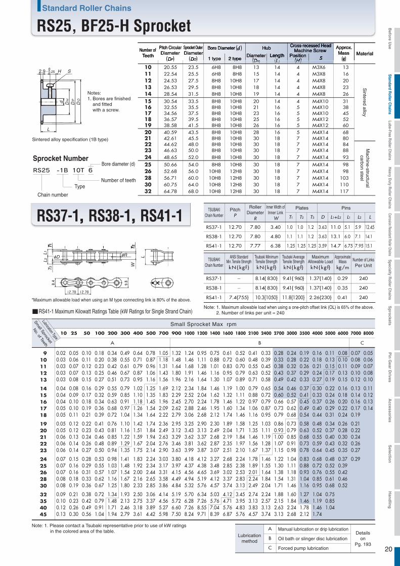
25 50.66 54.0 8H8 10H8 30 18 7 M4X14 9826 52.68 56.0 10H8 12H8 30 18 7 M4X14 9828 56.71 60.0 10H8 12H8 30 18 7 M4X14 10330 60.75 64.0 10H8 12H8 30 18 7 M4X14 11032 64.78 68.0 10H8 12H8 30 18 7 M4X14 117
10 20.55 23.5 6H8 8H8 13 14 4 M3X6 1311 22.54 25.5 6H8 8H8 15 14 4 M3X8 1612 24.53 27.5 8H8 10H8 17 14 4 M4X8 2013 26.53 29.5 8H8 10H8 18 14 4 M4X8 2314 28.54 31.5 8H8 10H8 19 14 4 M4X8 26
15 30.54 33.5 8H8 10H8 20 14 4 M4X10 3116 32.55 35.5 8H8 10H8 21 16 5 M4X10 3817 34.56 37.5 8H8 10H8 23 16 5 M4X10 4518 36.57 39.5 8H8 10H8 25 16 5 M4X12 5219 38.58 41.5 8H8 10H8 26 16 5 M4X12 6020 40.59 43.5 8H8 10H8 28 16 5 M4X14 6821 42.61 45.5 8H8 10H8 30 18 7 M4X14 8022 44.62 48.0 8H8 10H8 30 18 7 M4X14 8423 46.63 50.0 8H8 10H8 30 18 7 M4X14 8824 48.65 52.0 8H8 10H8 30 18 7 M4X14 93
20
2.9 - 0.25
T1 T2 T3 D L1+L2 L1 L2 L
RS37-1 12.70 7.80 3.40 1.0 1.0 1.2 3.63 11.0 5.1 5.9 12.45
RS38-1 12.70 7.80 4.80 1.1 1.1 1.2 3.63 13.1 6.0 7.1 14.1
RS41-1 12.70 7.77 6.38 1.25 1.25 1.25 3.59 14.7 6.75 7.95 15.1
RS37-1 - 8.14{ 830} 9.41{ 960} 1.37{140} 0.29 240
RS38-1 - 8.14{ 830} 9.41{ 960} 1.37{140} 0.35 240
RS41-1 7.4{755} 10.3{1050} 11.8{1200} 2.26{230} 0.41 240
A B C
10 25 50 100 200 300 400 500 700 900 1000 1200 1400 1600 1800 2100 2400 2700 3000 3500 4000 5000 6000 7000 8000
d DP
DO
DH
L
H S
L1L2
D
T1T3
RR
TW
L
2
R
Sintered alloy specification (1B type)
Notes:1. Bores are finished
and fitted with a screw.
Bore diameter (d)Sprocket Number
Chain number
TypeNumber of teeth
Number ofTeeth
Bore Diameter (d )Pitch CircularDiameter
(DP )
Sprocket OuterDiameter
(DO) Diameter(DH)
Length(L )
Approx.Mass
(g)Material
1 type 2 type
Hub
Position(H )
Cross-recessed HeadMachine Screw
Sintered alloy
Machine-structuralcarbon steel
Number of LinksPer Unit
Small Sprocket Max rpm
Small Sprocket
Lubrication Type
No. of Teeth
A Manual lubrication or drip lubricationDetails
onPg. 193
B Oil bath or slinger disc lubrication
C Forced pump lubrication
Lubricationmethod
RS41-1 Maximum Kilowatt Ratings Table (kW Ratings for Single Strand Chain)
TSUBAKIChain Number
PitchP
RollerDiameter
Inner Width ofInner Link
R W
Plates Pins
TSUBAKIChain Number kN{kg f } kN{kg f} kN{kg f}
MaximumAllowable LoadkN{kg f}
ApproximateMass
kg/m
Note: 1. Maximum allowable load when using a one-pitch offset link (OL) is 65% of the above. 2. Number of links per unit = 240
Note: 1. Please contact a Tsubaki representative prior to use of kW ratings in the colored area of the table.
ANSI StandardMin. Tensile Strength
Tsubaki MinimumTensile Strength
Tsubaki AverageTensile Strength
Standard Roller Chains
RS25, BF25-H Sprocket
RS37-1, RS38-1, RS41-1
*Maximum allowable load when using an M type connecting link is 80% of the above.
Befo
re Use
Standard R
oller Chains
Lube-Free Roller C
hainsH
eavy Duty R
oller Chains
Corrosion Resistant Roller ChainsS
pecialty Roller C
hainsS
pro
cketsP
in G
ear Drives
Accesso
riesS
election
Han
dlin
g

21
RS35-1 1 12.7 5.85 6.85 13.5
10.18.7 {887} 9.81{1000} 11.3{1150} 2.16{220} 0.33
RS35-2 2 22.8 10.9 11.9 24.5 17.4{1774} 19.6{2000} 22.6{2300} 3.63{370} 0.69
RS35-3 3 32.9 16.0 16.9 34.6 26.1{2661} 29.4{3000} 33.8{3450} 5.39{550} 1.05
A B C
50 100 300 500 700 900 1200 1500 1800 2100 2500 3000 3500 4000 4500 5000 5500 6000 6500 7000 7500 8000 8500 9000 10000
L1L
L
1
L1L
C
2
L1L
CC
2
1.25
1.25
4.78
L1L2
3.59 5.08
9.0
9.525 9.525
7.8
Triple strandSingle strand Double strand
RS35-1 Maximum Kilowatt Ratings Table (kW Ratings for Single Strand Chain)
Small Sprocket Max rpm
Small Sprocket
Lubrication Type
No. of Teeth
TSUBAKIChain Number L1+L2 L1 L2 L kN{kg f } kN{kg f } kN{kg f } kN{kg f } kg/m
Riveting
Drawing Scale 1/1.2
Numberof Strands
Pin Length Dimensions DimensionsTransverse
PitchOffset Pin
LengthC
Pin TypeMaximum
Allowable LoadApproximate
Mass
Note: 1. Maximum allowable load when using a one-pitch offset link (OL) is 65% of the above. 2. Number of links per unit = 320 3. Bushed chain.
Note: 1. KW rating when using a one-pitch offset link (OL) is 80% of the above. 2. Please contact a Tsubaki representative prior to use of kW ratings in the colored area of the table.
Number of chain strandsNumber of chain strands Multi-strand factorMulti-strand factor1.7 3.92.5 4.63.3 - -
A
B
C
Manual lubrication or drip lubricationDetails
onPg. 193
Oil bath or slinger disc lubrication
Forced pump lubrication
Lubricationmethod
Quintuple strandSextuple strand
Double strandTriple strand
Quadruple strand
Multi-strandfactor
ANSI StandardMin. Tensile Strength
Tsubaki MinimumTensile Strength
Tsubaki AverageTensile Strength
Standard Roller Chains RS Roller Chain
RS35
0.090.100.120.130.14
0.150.160.170.190.20
0.210.220.230.240.26
0.270.280.290.320.34
0.370.400.470.53
0.170.190.220.240.26
0.280.300.320.350.37
0.390.410.430.460.48
0.500.520.550.590.64
0.680.750.870.99
0.470.520.580.640.70
0.750.810.870.930.99
1.051.111.171.231.29
1.351.411.471.591.72
1.842.032.342.66
0.740.830.921.011.10
1.191.291.381.471.56
1.661.751.851.942.04
2.132.232.332.522.72
2.913.213.714.21
1.001.121.241.371.49
1.611.741.871.992.12
2.252.372.5
2.632.76
2.893.023.153.413.68
3.944.345.025.70
1.261.411.561.711.87
2.022.182.342.502.66
2.822.983.143.303.46
3.623.793.954.284.61
4.945.456.297.14
1.631.822.022.222.42
2.622.833.033.233.44
3.653.864.064.274.48
4.694.915.125.545.97
6.407.068.159.26
1.992.232.472.712.96
3.213.453.703.954.21
4.464.714.975.225.48
5.746.006.266.787.30
7.838.639.9611.3
2.342.632.913.203.49
3.784.074.364.664.96
5.255.555.856.166.46
6.767.077.377.998.60
9.2310.211.713.3
2.693.023.343.674.01
4.344.685.015.355.69
6.046.386.727.077.42
7.778.128.479.189.89
10.611.713.515.3
2.132.502.883.283.70
4.144.595.055.546.03
6.547.067.6
8.158.68
9.099.509.9110.711.6
12.413.715.817.9
1.621.902.192.502.82
3.153.493.854.214.59
4.985.375.786.206.63
7.067.517.978.909.87
10.912.415.218.1
1.291.511.741.982.23
2.502.773.053.343.64
3.954.264.594.925.26
5.615.966.327.067.83
8.639.8712.114.4
1.051.231.421.621.83
2.042.272.5
2.742.98
3.233.493.764.034.30
4.594.885.175.786.41
7.068.089.8711.8
0.881.031.191.361.53
1.711.902.092.292.50
2.712.933.153.373.61
3.854.094.344.855.37
5.926.778.279.87
0.750.881.021.161.31
1.461.621.791.962.13
2.312.502.692.883.08
3.283.493.704.144.59
5.055.787.068.43
0.650.770.881.011.13
1.271.411.551.701.85
2.002.162.332.502.67
2.853.033.213.593.98
4.385.016.127.31
0.570.670.770.881.00
1.111.231.361.491.62
1.761.902.042.192.34
2.502.662.823.153.49
3.854.405.376.41
0.510.600.690.780.88
0.991.091.211.321.44
1.561.691.811.942.08
2.212.352.502.793.10
3.413.904.775.69
0.460.530.610.700.79
0.880.981.081.181.29
1.401.511.621.741.86
1.982.112.232.502.77
3.053.494.265.09
0.410.480.550.630.71
0.800.880.971.071.16
1.261.361.461.571.68
1.791.902.022.252.50
2.753.153.85
0.370.440.500.570.65
0.720.800.880.971.05
1.141.231.331.421.52
1.621.721.832.042.27
2.502.863.49
0.340.400.460.520.59
0.660.730.810.880.96
1.041.131.211.301.39
1.481.571.671.872.07
2.282.61
0.310.370.420.480.54
0.610.670.740.810.88
0.961.031.111.191.28
1.361.451.531.711.90
2.092.39
0.270.310.360.410.46
0.520.570.630.690.75
0.820.880.951.021.09
1.161.231.311.461.62
910111213
1415161718
1920212223
2425262830
32354045
Befo
re Use
Standard R
oller Chains
Lube-Free Roller C
hainsH
eavy Duty R
oller Chains
Corrosion Resistant Roller ChainsS
pecialty Roller C
hainsS
pro
cketsP
in G
ear Drives
Accesso
riesS
election
Han
dlin
g
22
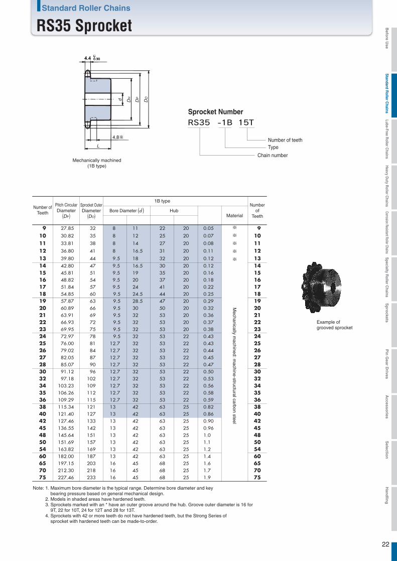
4.4 -0.30
L
d DH
DP
DO
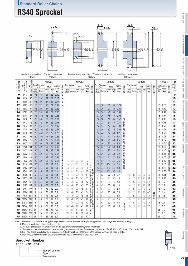
Note: 1. Maximum bore diameter is the typical range. Determine bore diameter and key bearing pressure based on general mechanical design.
2. Models in shaded areas have hardened teeth.3. Sprockets marked with an * have an outer groove around the hub. Groove outer diameter is 16 for
9T, 22 for 10T, 24 for 12T and 28 for 13T.4. Sprockets with 42 or more teeth do not have hardened teeth, but the Strong Series of
sprocket with hardened teeth can be made-to-order.
Example ofgrooved sprocket
Mechanically machined(1B type)
Sprocket Number
Chain number
TypeNumber of teeth
Bore Diameter (d )Number ofTeeth
Pitch CircularDiameter
(DP )
Sprocket OuterDiameter
(DO)Hub
Material
1B typeNumber
ofTeeth
Mechanically m
achined: machine-structural carbon steel
Standard Roller Chains
RS35 Sprocket
6065
182.00 187 13 42 63 25 1.4 197.15 203 16 45 68 25 1.6
6065
75 227.46 233 16 45 68 25 1.9 75
9 27.85 32 8 11 22 20 0.05 ※
※
※
※
※
9
10 30.82 35 8 12 25 20 0.07 1011 33.81 38 8 14 27 20 0.08 1112 36.80 41 8 16.5 31 20 0.11 1213 39.80 44 9.5 18 32 20 0.12 1314 42.80 47 9.5 16.5 30 20 0.12 1415 45.81 51 9.5 19 35 20 0.16 1516 48.82 54 9.5 20 37 20 0.18 1617 51.84 57 9.5 24 41 20 0.22 1718 54.85 60 9.5 24.5 44 20 0.25 1819 57.87 63 9.5 28.5 47 20 0.29 1920 60.89 66 9.5 30 50 20 0.32 2021 63.91 69 9.5 32 53 20 0.36 2122 66.93 72 9.5 32 53 20 0.37 2223 69.95 75 9.5 32 53 20 0.38 2324 72.97 78 9.5 32 53 22 0.43 2425 76.00 81 12.7 32 53 22 0.43 2526 79.02 84 12.7 32 53 22 0.44 2627 82.05 87 12.7 32 53 22 0.45 2728 85.07 90 12.7 32 53 22 0.47 2830 91.12 96 12.7 32 53 22 0.50 3032 97.18 102 12.7 32 53 22 0.53 3234 103.23 109 12.7 32 53 22 0.56 3435 106.26 112 12.7 32 53 22 0.58 3536 109.29 115 12.7 32 53 22 0.59 3638 115.34 121 13 42 63 25 0.82 384042
121.40 127 13 42 63 25 0.86 127.46 133 13 42 63 25 0.90
4042
45 136.55 142 13 42 63 25 0.96 454850
145.64 151 13 42 63 25 1.0151.69 157 13 42 63 25 1.1
4850
54 163.82 169 13 42 63 25 1.2 54
70 212.30 218 16 45 68 25 1.7 70
Befo
re Use
Standard R
oller Chains
Lube-Free Roller C
hainsH
eavy Duty R
oller Chains
Corrosion Resistant Roller ChainsS
pecialty Roller C
hainsS
pro
cketsP
in G
ear Drives
Accesso
riesS
election
Han
dlin
g
0.07 0.07 0.08 0.09 0.10
0.11 0.11 0.12 0.13 0.14
0.15 0.16 0.16 0.17 0.18
0.19 0.20 0.210.22 0.24
0.26 0.28 0.33 0.37
0.15 0.17 0.19 0.20 0.22
0.24 0.26 0.28 0.30 0.32
0.33 0.35 0.37 0.39 0.41
0.43 0.45 0.47 0.51 0.55
0.59 0.65 0.75 0.85
0.28 0.31 0.35 0.38 0.41
0.45 0.48 0.52 0.55 0.59
0.62 0.66 0.70 0.73 0.77
0.80 0.84 0.88 0.95 1.02
1.10 1.21 1.40 1.59
0.52 0.58 0.65 0.71 0.77
0.84 0.90 0.97 1.03 1.10
1.17 1.23 1.30 1.37 1.43
1.50 1.57 1.64 1.77 1.91
2.05 2.26 2.60 2.96
0.97 1.09 1.21 1.32 1.44
1.56 1.69 1.81 1.93 2.05
2.18 2.30 2.42 2.55 2.67
2.80 2.93 3.05 3.31 3.56
3.82 4.21 4.86 5.52
1.40 1.57 1.74 1.91 2.08
2.25 2.43 2.60 2.78 2.96
3.13 3.31 3.49 3.67 3.85
4.03 4.21 4.40 4.76 5.13
5.50 6.06 7.00 7.95
1.81 2.03 2.25 2.47 2.69
2.92 3.14 3.37 3.60 3.83
4.06 4.29 4.52 4.76 4.99
5.22 5.46 5.70 6.17 6.65
7.13 7.85 9.07 10.3
2.21 2.48 2.75 3.02 3.29
3.57 3.84 4.12 4.40 4.68
4.96 5.24 5.53 5.81 6.10
6.39 6.67 6.96 7.54 8.13
8.71 9.60 11.1 12.6
3.00 3.36 3.72 4.09 4.46
4.83 5.20 5.58 5.96 6.34
6.72 7.10 7.48 7.87 8.26
8.65 9.03 9.43 10.2 11.0
11.8 13.0 15.0 17.0
3.75 4.21 4.67 5.13 5.59
6.06 6.52 7.00 7.47 7.94
8.42 8.90 9.38 9.87 10.4
10.8 11.3 11.8 12.8 13.8
14.8 16.3 18.8 21.4
3.754.405.075.646.15
6.667.177.698.218.73
9.26 9.79 10.3 10.8 11.4
11.9 12.5 13.0 14.1 15.2
16.3 17.9 20.7 23.5
3.75 4.40 5.07 5.67 6.18
6.70 7.21 7.74 8.26 8.79
9.43 10.2 11.0 11.7 12.6
13.4 14.1 14.7 16.0 17.2
18.4 20.3 24.1 27.7
3.75 4.40 5.07 5.67 6.18
6.70 7.21 7.74 8.26 8.79
9.43 10.2 11.0 11.7 12.6
13.4 14.1 14.7 16.0 17.2
18.4 20.3 24.1 28.8
3.07 3.60 4.15 4.73 5.34
5.96 6.61 7.28 7.98 8.69
9.4310.2 11.0 11.7 12.6
13.4 14.1 14.7 16.0 17.2
18.4 20.3 24.1 28.8
2.58 3.02 3.48 3.97 4.47
5.00 5.54 6.10 6.69 7.28
7.90 8.53 9.18 9.84 10.5
11.2 11.9 12.6 14.1 15.7
17.3 19.8 24.1 28.8
2.04 2.39 2.76 3.15 3.55
3.97 4.40 4.84 5.31 5.78
6.27 6.77 7.28 7.81 8.35
8.90 9.46 10.0 11.2 12.4
13.7 15.7 19.2 22.9
1.67 1.96 2.26 2.58 2.90
3.25 3.60 3.97 4.34 4.73
5.13 5.54 5.96 6.39 6.83
7.28 7.74 8.21 9.18 10.2
11.2 12.8 15.7 18.7
1.40 1.64 1.89 2.16 2.43
2.72 3.02 3.32 3.64 3.97
4.30 4.64 5.00 5.36 5.73
6.10 6.49 6.88 7.69 8.53
9.40 10.8 13.1 15.7
1.20 1.40 1.62 1.84 2.08
2.32 2.58 2.84 3.11 3.39
3.67 3.97 4.27 4.57 4.89
5.21 5.54 5.88 6.57 7.28
8.03 9.18 11.2 13.4
0.95 1.11 1.28 1.46 1.65
1.84 2.04 2.25 2.47 2.69
2.91 3.15 3.39 3.63 3.88
4.14 4.40 4.66 5.21 5.78
6.37 7.28 8.90 10.6
0.78 0.91 1.05 1.20 1.35
1.51 1.67 1.84 2.02 2.20
2.38 2.58 2.77 2.97 3.18
3.39 3.60 3.82 4.27 4.73
5.21 5.96 7.28 8.69
0.56 0.65 0.75 0.86 0.97
1.08 1.20 1.32 1.44 1.57
1.71 1.84 1.98 2.13 2.27
2.42 2.58 2.73 3.05 3.39
3.73 4.27 5.21
0.42 0.50 0.57 0.65 0.73
0.82 0.91 1.00 1.10 1.20
1.30 1.40 1.51 1.62 1.73
1.84 1.96 2.08 2.32 2.58
0.34 0.39 0.45 0.52 0.58
0.65 0.72 0.80 0.87 0.95
1.03 1.11 1.20 1.28 1.37
1.46
0.27 0.32 0.37 0.42 0.48
0.53 0.59 0.65 0.71
23
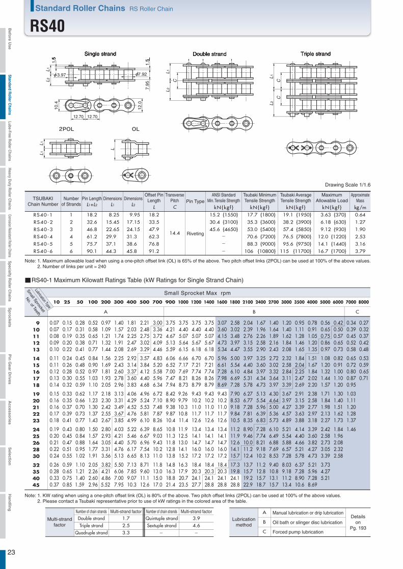
RS40-1 1 18.2 8.25 9.95 18.2
14.4
15.2 {1550} 17.7 {1800} 19.1 {1950} 3.63 {370} 0.64
RS40-5 5 75.7 37.1 38.6 76.8 88.3 {9000} 95.6 {9750} 14.1 {1440} 3.16
RS40-6 6 90.1 44.3 45.8 91.2 106 {10800} 115 {11700} 16.7 {1700} 3.79
RS40-2 2 32.6 15.45 17.15 33.5 30.4 {3100} 35.3 {3600} 38.2 {3900} 6.18 {630} 1.27
RS40-3 3 46.8 22.65 24.15 47.9 45.6 {4650} 53.0 {5400} 57.4 {5850} 9.12 {930} 1.90
RS40-4 4 61.2 29.9 31.3 62.3 70.6 {7200} 76.5 {7800} 12.0 {1220} 2.53
A B C
10 25 50 100 200 300 400 500 700 900 1000 1200 1400 1600 1800 2100 2400 2700 3000 3500 4000 5000 6000 7000 8000
910111213
1415161718
1920212223
2425262830
32354045
L
L
1L1
C
L1L2
CC
L1L2
-
-
-
L1L2
10.4
12.0
12.70 12.70
1.5
3.97
1.5
7.92
7.95
Triple strandSingle strand Double strand
RS40-1 Maximum Kilowatt Ratings Table (kW Ratings for Single Strand Chain)
Small Sprocket Max rpm
Small Sprocket
Lubrication Type
No. of Teeth
Number of chain strandsNumber of chain strands Multi-strand factorMulti-strand factor1.7 3.92.5 4.63.3 - -
A
B
C
Manual lubrication or drip lubricationDetails
onPg. 193
Oil bath or slinger disc lubrication
Forced pump lubrication
Lubricationmethod
Quintuple strandSextuple strand
Double strandTriple strand
Quadruple strand
Multi-strandfactor
Riveting
Note: 1. Maximum allowable load when using a one-pitch offset link (OL) is 65% of the above. Two pitch offset links (2POL) can be used at 100% of the above values.2. Number of links per unit = 240
L1+L2 L1 L2 L kN{kg f } kN{kg f } kN{kg f } kN{kg f } kg/m
Drawing Scale 1/1.6
Dimensions Dimensions
C
TSUBAKIChain Number
Numberof Strands
Pin LengthTransverse
PitchOffset Pin
Length Pin TypeMaximum
Allowable LoadApproximate
Mass
Note: 1. KW rating when using a one-pitch offset link (OL) is 80% of the above. Two pitch offset links (2POL) can be used at 100% of the above values.2. Please contact a Tsubaki representative prior to use of kW ratings in the colored area of the table.
ANSI StandardMin. Tensile Strength
Tsubaki MinimumTensile Strength
Tsubaki AverageTensile Strength
Standard Roller Chains RS Roller Chain
RS40Befo
re Use
Standard R
oller Chains
Lube-Free Roller C
hainsH
eavy Duty R
oller Chains
Corrosion Resistant Roller ChainsS
pecialty Roller C
hainsS
pro
cketsP
in G
ear Drives
Accesso
riesS
election
Han
dlin
g
24
7.3 -0.36
L
d DH
DP
DO
L
7.3
d DH
DP
DO
7.121.5
-0.36
L
d DH
DP
DO
7.121.5
-0.36
L
d DH
DP
DO
7.121.5
- -0.36
L
d DH
DP
DO
7.3 00.36
d DP
DO
00.36
Mechanically machined1B type
Welded construction1C type
Mechanically machined
Welded construction Welded construction2C type2B type
2B type 1A type
Bore Diameter(d ) Hub
PilotBore
Diameter MaximumDiameter(DH )
Length(L )
Approx.Mass
(kg)
Num
ber ofTeeth
Num
ber ofTeeth
Pitch C
ircularD
iameter
(DP)
Sprocket Outer Diameter(D
O)
Material
1B type 1C type
Bore Diameter(d ) Hub
PilotBore
Diameter MaximumDiameter(DH )
Length(L )
Approx.Mass(kg)
Material
Approx.Mass(kg)
Material
Pilot B
oreD
iameter
d
Welded specification: m
achine-structuralcarbon steel (teeth) and structural rolled steel (hub)
Mechanically m
achined: machine-structural carbon steel
Precut specification: m
achine-structural carbon steel
Machine-structural carbon steel
Note: 1. Maximum bore diameter is the typical range. Determine bore diameter and key bearing pressure based on general mechanical design.2. Models in shaded areas have hardened teeth.3. The outer diameters above are given for the 1B type. Diameters vary slightly for all other types.4. 1B-type sprockets marked with an * have an outer groove around the hub. Groove outer diameter is 21 for 9T, 25 for 10T, 30 for 11T and 32 for 12T.5. For single-strand sprockets without hardened teeth, the Strong Series of sprocket with hardened teeth can be made-to-order.6. Welded specification: machine-structural carbon steel (teeth) and structural rolled steel (hub)
2C type
Bore Diameter(d ) Hub
PilotBore
Diameter MaximumDiameter(DH )
Length(L )
Approx.Mass(kg)
Material
Bore Diameter(d ) Hub
PilotBore
Diameter MaximumDiameter(DH )
Length(L )
Approx.Mass
(kg)
Material
Standard Roller Chains
RS40 Sprocket
50 202.26 209 18 5054 218.42 226 1860 242.66 250 1865 262.87 270 23
75 303.28 311 23
9 37.13 43 9.5 15 28 22 0.10 0.13 0.17 0.21 0.22 0.28 0.33 0.37 0.44 0.49 0.57 0.73 0.82 0.91 0.98 0.80 0.83 0.87 0.91 0.95 1.0 1.3 1.4 1.4 1.5 1.6 1.7 2.0 2.2 2.4 2.5 2.8 3.3 4.0 4.5 5.0
※ 910 41.10 47 9.5 16.5 32 2211 45.08 51 9.5 20 37 2212 49.07 55 9.5 22 40 22 9.5 18 32 35 0.29
0.36 0.44 0.53 0.62 0.71 0.80 0.93 1.2 1.3 1.5 1.6 1.8 2.0 2.2 2.4 2.6 3.0 4.2 4.9 3.9 4.0 4.3 4.6 5.0 5.5 6.0 6.5 7.3 8.8
13 53.07 59 9.5 20 37 22 12.7 20 37 3514 57.07 63 9.5 24 42 22 12.7 24 42 35 1415 61.08 67 9.5 28.5 46 22 12.7 29 46 35 1616 65.10 71 12.7 30 50 22 12.7 30 50 35 1617 69.12 76 12.7 32 54 22 12.7 32 54 35 16
16 0.08 0.10 0.12 0.14 0.16 0.18 0.21 0.24 0.26 0.29 0.32 0.35 0.39 0.42 0.46 0.50 0.53 0.62 0.71 0.80 0.85 0.90 1.0 1.1 1.2 1.4 1.6 1.8 2.1 2.6 3.0 3.5 4.0
1616
18 73.14 80 12.7 35 57 22 12.7 35 57 35 1619 77.16 84 12.7 39.5 62 22 12.7 40 62 35 16 1920 81.18 88 12.7 45.5 67 25 12.7 46 67 40 1621 85.21 92 12.7 45.5 71 25 12.7 47 71 40 1622 89.24 96 12.7 50 75 25 12.7 50 75 40 16
1623 93.27 100 12.7 50 77 25 12.7 50 77 4024 97.30 104 12.7 42 63 25 12.7 55 83 40 16 2425 101.33 108 12.7 42 63 25 12.7 59 87 40 1626 105.36 112 12.7 42 63 25 12.7 62 91 40
12.7 65 95 4012.7 67 99 40
161616
27 109.40 116 12.7 42 63 2528 113.43 120 12.7 42 63 2530 121.50 128 12.7 42 63 25 12.7 73 106 40
12.7 78 115 5012.7 84 124 50
16 3032 129.57 137 16 45 68 28 1634 137.64 145 16 45 68 28 1635 141.68 149 16 45 68 28 16 63 93 50
16 63 93 5016 63 93 50
16 63 93 70 4.9 5.1 5.4 5.7 6.0 6.5 7.1 7.5 8.4 9.8
16 63 93 7016 63 93 70
1636 145.72 153 16 45 68 28 16 48 73 45
16 48 73 4516 48 73 4516 48 73 4516 48 73 4516 48 73 45 1.7
1.8 1.9 2.0 2.1 2.1 2.2 2.3 2.4 2.6 2.8 3.0 3.3 3.8 4.7 5.2 5.7
1638 153.79 161 16 45 68 28 16 48 73 45 16 3840 161.87 169 16 45 68 28 16 48 73 45 16 63 93 50
16 63 93 5016 63 93 7016 63 93 70
1642 169.94 177 18 48 73 32 18 48 73 45 1845 182.06 189 18 48 73 32 18 48 73 45 18 63 93 50
18 63 93 5018 63 93 50
18 63 93 7018 63 93 7018 63 93 70
1848 194.18 201 18 48 73 32 18 48 73 45 18
18 48 73 32 18 48 73 4518 48 73 32 18 48 73 45 18 63 93 50 18 63 93 7018 48 73 32 18 48 73 45 18 63 93 50 18 63 93 7023 55 83 32 23 55 83 50
70 283.07 290 23 55 83 32 23 55 83 50 2323 55 83 32 23 55 83 50
10111213
15161718
20212223
25262728
32343536
40424548
5460657075
※
※
※
Note 6
Note 6
Sprocket Number
Chain numberTypeNumber of teeth
Befo
re Use
Standard R
oller Chains
Lube-Free Roller C
hainsH
eavy Duty R
oller Chains
Corrosion Resistant Roller ChainsS
pecialty Roller C
hainsS
pro
cketsP
in G
ear Drives
Accesso
riesS
election
Han
dlin
g
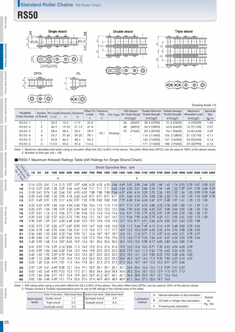
0.14 0.16 0.18 0.20 0.21
0.23 0.25 0.27 0.29 0.30
0.32 0.34 0.36 0.38 0.40
0.41 0.43 0.45 0.49 0.53
0.57 0.62 0.72 0.82
0.33 0.37 0.41 0.45 0.49
0.53 0.57 0.61 0.65 0.69
0.73 0.78 0.82 0.86 0.90
0.95 0.99 1.03 1.12 1.20
1.29 1.42 1.64 1.86
0.61 0.69 0.76 0.83 0.91
0.99 1.06 1.14 1.22 1.29
1.37 1.45 1.53 1.61 1.68
1.76 1.84 1.92 2.08 2.24
2.41 2.65 3.06 3.48
1.14 1.28 1.42 1.56 1.70
1.84 1.98 2.12 2.27 2.41
2.56 2.70 2.85 3.00 3.14
3.29 3.44 3.59 3.89 4.19
4.49 4.95 5.71 6.49
2.13 2.39 2.64 2.90 3.17
3.43 3.70 3.96 4.23 4.50
4.77 5.04 5.32 5.59 5.87
6.14 6.42 6.70 7.25 7.81
8.38 9.23 10.7 12.1
3.07 3.44 3.81 4.18 4.56
4.94 5.32 5.71 6.10 6.48
6.87 7.26 7.66 8.05 8.45
8.85 9.24 9.64 10.4 11.3
12.1 13.3 15.4 17.4
3.97 4.45 4.93 5.42 5.91
6.40 6.90 7.40 7.90 8.40
8.90 9.41 9.92 10.4 10.9
11.5 12.0 12.5 13.5 14.6
15.6 17.2 19.9 22.6
4.86 5.44 6.03 6.63 7.22
7.83 8.43 9.04 9.65 10.3
10.9 11.5 12.1 12.8 13.4
14.0 14.6 15.3 16.5 17.8
19.1 21.1 24.3 27.6
6.35 7.11 7.88 8.71 9.78
10.6 11.4 12.2 13.1 13.9
14.7 15.6 16.4 17.3 18.1
19.0 19.8 20.7 22.4 24.1
25.9 28.5 32.9 37.4
6.35 7.11 7.88 8.71 9.82
11.0 12.2 13.4 14.7 15.8
16.8 17.7 18.7 19.6 20.6
21.6 22.5 23.5 25.5 27.5
30.1 34.4 41.3 46.9
6.35 7.11 7.88 8.71 9.82
11.0 12.2 13.4 14.7 15.8
16.8 17.7 18.7 19.6 20.6
21.6 22.5 23.5 25.5 27.5
30.1 34.4 42.1 48.9
5.66 6.62 7.64 8.71 9.82
11.0 12.2 13.4 14.7 15.8
16.8 17.7 18.7 19.6 20.6
21.6 22.5 23.5 25.5 27.5
30.1 34.4 42.1 48.9
4.49 5.26 6.07 6.91 7.79
8.71 9.66 10.6 11.7 12.7
13.8 14.9 16.0 17.2 18.3
19.5 20.8 22.0 24.6 27.3
30.1 34.4 42.1 48.9
3.67 4.30 4.96 5.66 6.38
7.13 7.90 8.71 9.54 10.4
11.3 12.2 13.1 14.0 15.0
16.0 17.0 18.0 20.2 22.4
24.6 28.2 34.4 41.1
3.08 3.61 4.16 4.74 5.34
5.97 6.62 7.30 7.99 8.71
9.44 10.2 11.0 11.8 12.6
13.4 14.3 15.1 16.9 18.7
20.6 23.6 28.8 34.4
2.44 2.86 3.30 3.76 4.24
4.74 5.26 5.79 6.34 6.91
7.49 8.09 8.71 9.34 9.98
10.6 11.3 12.0 13.4 14.9
16.4 18.7 22.9 27.3
2.00 2.34 2.70 3.08 3.47
3.88 4.30 4.74 5.19 5.66
6.13 6.62 7.13 7.64 8.17
8.71 9.26 9.82 11.0 12.2
13.4 15.3 18.7 22.4
1.68 1.96 2.26 2.58 2.91
3.25 3.61 3.97 4.35 4.74
5.14 5.55 5.97 6.41 6.85
7.30 7.76 8.23 9.20 10.2
11.2 12.9 15.7 18.7
1.43 1.68 1.93 2.20 2.48
2.78 3.08 3.39 3.71 4.05
4.39 4.74 5.10 5.47 5.85
6.23 6.62 7.03 7.85 8.71
9.59 11.0 13.4 16.0
1.14 1.33 1.53 1.75 1.97
2.20 2.44 2.69 2.95 3.21
3.48 3.76 4.05 4.34 4.64
4.94 5.26 5.58 6.23 6.91
7.61 8.71 10.6
0.93 1.09 1.26 1.43 1.61
1.80 2.00 2.20 2.41 2.63
2.85 3.08 3.31 3.55 3.80
4.05 4.30 4.56 5.10 5.66
6.23 7.13
0.78 0.91 1.05 1.20 1.35
1.51 1.68 1.85 2.02 2.20
2.39 2.58 2.78 2.98 3.18
3.39 3.61 3.82 4.27
0.67 0.78 0.90 1.02 1.15
1.29 1.43 1.58 1.73 1.88
2.04 2.20 2.37 2.54
0.58 0.68 0.78 0.89 1.00
1.12 1.24 1.37 1.50
0.51 0.59 0.68 0.78
25
RS50-1 1 22.2 10.3 11.9 22.6
18.1
24 {2447} 28.4 {2900} 31.4 {3200} 6.37{650} 1.04
RS50-5 5 94.8 46.5 48.3 96.2 142 {14500} 157 {16000} 24.9{2540} 5.14
RS50-6 6 113.0 55.6 57.4 114.4 171 {17400} 188 {19200} 29.3{2990} 6.16
RS50-2 2 40.5 19.35 21.15 41.8 48 {4895} 56.9 {5800} 62.8 {6400} 10.7{1100} 2.07
RS50-3 3 58.6 28.4 30.2 59.9 72 {7342} 85.3 {8700} 94.1 {9600} 16.0{1630} 3.09
RS50-4 4 76.7 37.45 39.25 78.1 114 {11600} 126 {12800} 21.1{2150} 4.11
A B C
10 25 50 100 200 300 400 500 700 900 1000 1200 1400 1600 1800 2100 2400 2700 3000 3500 4000 4500 5000 5500 6000
910111213
1415161718
1920212223
2425262830
32354045
L1L1
L
L1L2
C
L1L2
CC
--
-
13.0
15.0
15.875 15.875
2.0
5.09
2.0
10.16
9.53
L 1L2
Triple strandSingle strand Double strand
RS50-1 Maximum Kilowatt Ratings Table (kW Ratings for Single Strand Chain)
Small Sprocket Max rpm
Small Sprocket
Lubrication Type
No. of Teeth
Number of chain strandsNumber of chain strands Multi-strand factorMulti-strand factor1.7 3.92.5 4.63.3 - -
A
B
C
Manual lubrication or drip lubricationDetails
onPg. 193
Oil bath or slinger disc lubrication
Forced pump lubrication
Lubricationmethod
Quintuple strandSextuple strand
Double strandTriple strand
Quadruple strand
Multi-strandfactor
Riveting
Note: 1. Maximum allowable load when using a one-pitch offset link (OL) is 65% of the above. Two pitch offset links (2POL) can be used at 100% of the above values.2. Number of links per unit = 192
L1+L2 L1 L2 L kN{kg f } kN{kg f } kN{kg f } kN{kg f } kg/m
Drawing Scale 1/2
Dimensions Dimensions
C
TSUBAKIChain Number
Numberof Strands
Pin LengthTransverse
PitchOffset Pin
Length Pin TypeMaximum
Allowable LoadApproximate
Mass
Note: 1. KW rating when using a one-pitch offset link (OL) is 80% of the above. Two pitch offset links (2POL) can be used at 100% of the above values.2. Please contact a Tsubaki representative prior to use of kW ratings in the colored area of the table.
ANSI StandardMin. Tensile Strength
Tsubaki MinimumTensile Strength
Tsubaki AverageTensile Strength
Standard Roller Chains RS Roller Chain
RS50Befo
re Use
Standard R
oller Chains
Lube-Free Roller C
hainsH
eavy Duty R
oller Chains
Corrosion Resistant Roller ChainsS
pecialty Roller C
hainsS
pro
cketsP
in G
ear Drives
Accesso
riesS
election
Han
dlin
g
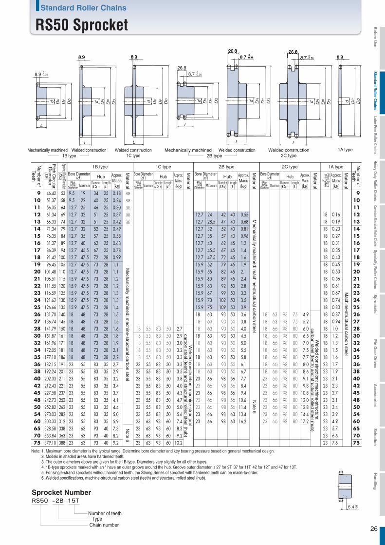
50 252.82 262 23 5054 273.03 282 2360 303.33 312 2365 328.58 338 23
75 379.10 388 23
9 46.42 53 9.5 19 34 25 0.18 0.24 0.30 0.37 0.42 0.49 0.58 0.68 0.78 0.99 1.1 1.1 1.2 1.2 1.3 1.3 1.4 1.5 1.5 1.6 1.8 1.9 2.1 2.2 2.7 2.9 3.2 3.4 3.7 4.1 4.4 5.0 5.9 7.3 8.2 9.2
※ 910 51.37 58 9.5 22 40 2511 56.35 64 12.7 25 46 2512 61.34 69 12.7 32 51 25 12.7 24 42 40 0.55
0.680.810.961.2 1.4 1.6 1.9 2.1 2.4 2.8 3.2 3.5 3.9 3.6 3.8 4.0 4.5 5.0 5.5 5.8 6.1 6.7 7.7 8.4 9.4
10.6 11.4 13.4 16.2
18 0.16 0.19 0.23 0.27 0.31 0.35 0.40 0.45 0.50 0.56 0.61 0.67 0.74 0.80 0.87 0.94 1.0 1.2 1.3 1.5 1.6 1.7 1.9 2.1 2.3 2.7 3.1 3.4 3.9 4.9 5.7 6.6 7.6
13 66.33 74 12.7 32 51 25 12.7 28.5 47 40 1814 71.34 79 12.7 32 52 25 12.7 32 52 40 18 1415 76.35 84 12.7 35 57 25 12.7 35 57 40 1816 81.37 89 12.7 40 62 25 12.7 40 62 45 1817 86.39 94 12.7 45.5 67 25 12.7 45.5 67 45 1818 91.42 100 12.7 47.5 72 28 12.7 47.5 72 45 1819 96.45 105 12.7 47.5 73 28 15.9 52 79 45 18 1920 101.48 110 12.7 47.5 73 28 15.9 55 82 45 1821 106.51 115 15.9 47.5 73 28 15.9 60 89 45 1822 111.55 120 15.9 47.5 73 28 15.9 63 92 50 18
1823 116.59 125 15.9 47.5 73 28 15.9 67 99 5024 121.62 130 15.9 47.5 73 28 15.9 70 102 50 18 2425 126.66 135 15.9 47.5 73 28 15.9 75 109 50 1826 131.70 140 18 48 73 28 18 63 93 50
18 63 93 5018 63 93 50
1827 136.74 145 18 48 73 28 1828 141.79 150 18 48 73 28 1830 151.87 161 18 48 73 28 18 63 93 50
18 63 93 5018 63 93 50
18 3032 161.96 171 18 48 73 28 1834 172.05 181 18 48 73 28 1835 177.10 186 18 48 73 28 18 63 93 50
18 63 93 5018 66 98 8018 66 98 8018 66 98 80
23 66 98 80
23 66 98 80
18 66 98 8018 66 98 8018 66 98 8018 66 98 8018 63 93 7518 63 93 75 4.9
5.2 6.0 6.5 7.0 7.5 7.7 8.0 8.6 9.1 9.8
10.8 12.0 12.8 14.4 17.2
1836 182.15 191 23 55 83 35 23 55 83 50
18 55 83 5018 55 83 5018 55 83 5018 55 83 5018 55 83 50 2.7
2.9 3.0 3.2 3.3 3.3 3.5 3.8 4.0 4.3 4.7 5.0 5.6 7.4 8.3 9.2
10.2
2338 192.24 201 23 55 83 35 23 55 83 50 23 3840 202.33 211 23 55 83 35 23 55 83 50 23 66 98 56
18 63 93 50
23 66 98 5623 66 98 80 23
42 212.43 221 23 55 83 35 23 55 83 50 2345 227.58 237 23 55 83 35 23 55 83 50 23 66 98 56 23 66 98 80
23 66 98 80
2348 242.73 252 23 55 83 35 23 55 83 50 23
23 55 83 35 23 55 83 5023 55 83 35 23 55 83 50 23 66 98 63
23 66 98 5623 66 98 56
23 66 98 8023 55 83 35 23 63 93 60 23 66 98 63 23 66 98 8023 63 93 40 23 63 93 60
70 353.84 363 23 63 93 40 23 63 93 60 2323 63 93 40 23 63 93 60
10111213
15161718
20212223
25262728
32343536
40424548
5460657075
※
※
※
※
26
8.9 -0.36
8.9 8.9 8.98.726.8
-0.36
8.726.8
-0.36
8.726.8
-0.36
L
d DH
DP
DO
L
d DH
DP
DO
Ld DH
DP
DO
L
d DH
DP
DO
L
d DH
DP
DO
L
d dDH
DP
DO
DP
DO
Welded construction1C type
Mechanically machined Welded construction1B type
Mechanically machined Welded construction2B type
Welded construction2C type
1A type
Machine-structural carbon steel
Note 6
Note 6
Note: 1. Maximum bore diameter is the typical range. Determine bore diameter and key bearing pressure based on general mechanical design.2. Models in shaded areas have hardened teeth.3. The outer diameters above are given for the 1B type. Diameters vary slightly for all other types.4. 1B-type sprockets marked with an * have an outer groove around the hub. Groove outer diameter is 27 for 9T, 37 for 11T, 42 for 12T and 47 for 13T.5. For single-strand sprockets without hardened teeth, the Strong Series of sprocket with hardened teeth can be made-to-order.6. Welded specifications, machine-structural carbon steel (teeth) and structural rolled steel (hub).
Sprocket Number
Chain numberType
Number of teeth
Mechanically m
achined: machine-structural carbon steel
Mechanically m
achined: machine-structural carbon steel
Welded construction: m
achine-structuralcarbon steel (teeth) and structural rolled steel (hub)
Welded construction: m
achine-structuralcarbon steel (teeth) and structural rolled steel (hub)
2B type 1A type
Bore Diameter(d ) Hub
PilotBore
Diameter MaximumDiameter(DH )
Length(L )
Approx.Mass
(kg)
Num
ber ofTeeth
Num
ber ofTeeth
Pitch C
ircularD
iameter
(DP)
Sprocket Outer Diameter(D
O)
Material
1B type 1C type
Bore Diameter(d ) Hub
PilotBore
Diameter MaximumDiameter(DH )
Length(L )
Approx.Mass(kg)
Material
Approx.Mass(kg)
Material
Pilot B
oreD
iameter
d
2C type
Bore Diameter(d ) Hub
PilotBore
Diameter MaximumDiameter(DH )
Length(L )
Approx.Mass(kg)
Material
Bore Diameter(d ) Hub
PilotBore
Diameter MaximumDiameter(DH )
Length(L )
Approx.Mass
(kg)
Material
Standard Roller Chains
RS50 Sprocket Befo
re Use
Standard R
oller Chains
Lube-Free Roller C
hainsH
eavy Duty R
oller Chains
Corrosion Resistant Roller ChainsS
pecialty Roller C
hainsS
pro
cketsP
in G
ear Drives
Accesso
riesS
election
Han
dlin
g
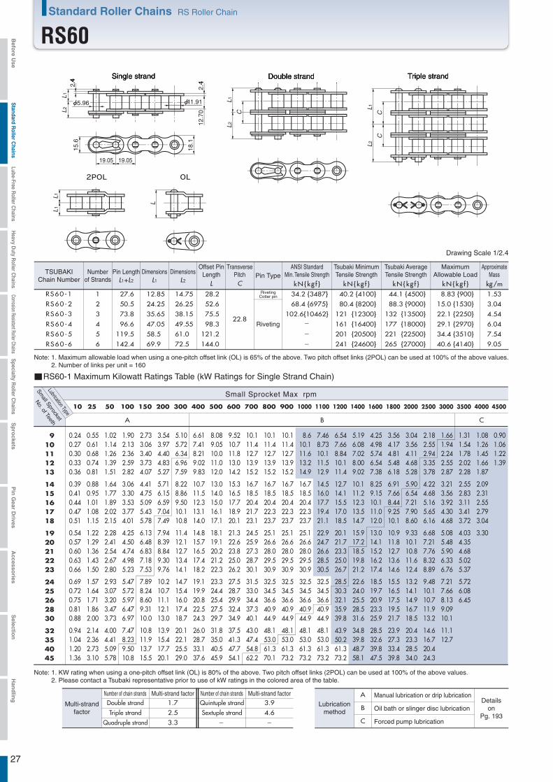
0.24 0.27 0.30 0.33 0.36
0.39 0.41 0.44 0.47 0.51
0.54 0.57 0.60 0.63 0.66
0.69 0.72 0.75 0.81 0.88
0.94 1.04 1.20 1.36
0.55 0.61 0.68 0.74 0.81
0.88 0.95 1.01 1.08 1.15
1.22 1.29 1.36 1.43 1.50
1.57 1.64 1.71 1.86 2.00
2.14 2.36 2.73 3.10
1.02 1.14 1.26 1.39 1.51
1.64 1.77 1.89 2.02 2.15
2.28 2.41 2.54 2.67 2.80
2.93 3.07 3.20 3.47 3.73
4.00 4.41 5.09 5.78
1.90 2.13 2.36 2.59 2.82
3.06 3.30 3.53 3.77 4.01
4.25 4.50 4.74 4.98 5.23
5.47 5.72 5.97 6.47 6.97
7.47 8.23 9.50 10.8
2.73 3.06 3.40 3.73 4.07
4.41 4.75 5.09 5.43 5.78
6.13 6.48 6.83 7.18 7.53
7.89 8.24 8.60 9.31 10.0
10.8 11.9 13.7 15.5
3.54 3.97 4.40 4.83 5.27
5.71 6.15 6.59 7.04 7.49
7.94 8.39 8.84 9.30 9.76
10.2 10.7 11.1 12.1 13.0
13.9 15.4 17.7 20.1
5.10 5.72 6.34 6.96 7.59
8.22 8.86 9.50 10.1 10.8
11.4 12.1 12.7 13.4 14.1
14.7 15.4 16.0 17.4 18.7
20.1 22.1 25.5 29.0
6.61 7.41 8.21 9.02 9.83
10.7 11.5 12.3 13.1 14.0
14.8 15.7 16.5 17.4 18.2
19.1 19.9 20.8 22.5 24.3
26.0 28.7 33.1 37.6
8.08 9.05 10.0 11.0 12.0
13.0 14.0 15.0 16.1 17.1
18.1 19.1 20.2 21.2 22.3
23.3 24.4 25.4 27.5 29.7
31.8 35.0 40.5 45.9
9.52 10.7 11.8 13.0 14.2
15.3 16.5 17.7 18.9 20.1
21.3 22.6 23.8 25.0 26.2
27.5 28.7 29.9 32.4 34.9
37.5 41.3 47.7 54.1
10.1 11.4 12.7 13.9 15.2
16.7 18.5 20.4 21.7 23.1
24.5 25.9 27.3 28.7 30.1
31.5 33.0 34.4 37.3 40.1
43.0 47.4 54.8 62.2
10.1 11.4 12.7 13.9 15.2
16.7 18.5 20.4 22.3 23.7
25.1 26.6 28.0 29.5 30.9
32.5 34.5 36.6 40.9 44.9
48.1 53.0 61.3 70.1
10.1 11.4 12.7 13.9 15.2
16.7 18.5 20.4 22.3 23.7
25.1 26.6 28.0 29.5 30.9
32.5 34.5 36.6 40.9 44.9
48.1 53.0 61.3 73.2
8.6 10.1 11.6 13.2 14.9
16.7 18.5 20.4 22.3 23.7
25.1 26.6 28.0 29.5 30.9
32.5 34.5 36.6 40.9 44.9
48.1 53.0 61.3 73.2
7.46 8.73 10.1 11.5 12.9
14.5 16.0 17.7 19.4 21.1
22.9 24.7 26.6 28.5 30.5
32.5 34.5 36.6 40.9 44.9
48.1 53.0 61.3 73.2
6.54 7.66 8.84 10.1 11.4
12.7 14.1 15.5 17.0 18.5
20.1 21.7 23.3 25.0 26.7
28.5 30.3 32.1 35.9 39.8
43.9 50.2 61.3 73.2
5.19 6.08 7.02 8.00 9.02
10.1 11.2 12.3 13.5 14.7
15.9 17.2 18.5 19.8 21.2
22.6 24.0 25.5 28.5 31.6
34.8 39.8 48.7 58.1
4.25 4.98 5.74 6.54 7.38
8.25 9.15 10.1 11.0 12.0
13.0 14.1 15.2 16.2 17.4
18.5 19.7 20.9 23.3 25.9
28.5 32.6 39.8 47.5
3.56 4.17 4.81 5.48 6.18
6.91 7.66 8.44 9.25 10.1
10.9 11.8 12.7 13.6 14.6
15.5 16.5 17.5 19.5 21.7
23.9 27.3 33.4 39.8
3.04 3.56 4.11 4.68 5.28
5.90 6.54 7.21 7.90 8.60
9.33 10.1 10.8 11.6 12.4
13.2 14.1 14.9 16.7 18.5
20.4 23.3 28.5 34.0
2.18 2.55 2.94 3.35 3.78
4.22 4.68 5.16 5.65 6.16
6.68 7.21 7.76 8.32 8.89
9.48 10.1 10.7 11.9 13.2
14.6 16.7 20.4 24.3
1.66 1.94 2.24 2.55 2.87
3.21 3.56 3.92 4.30 4.68
5.08 5.48 5.90 6.33 6.76
7.21 7.66 8.13 9.09 10.1
11.1 12.7
1.31 1.54 1.78 2.02 2.28
2.55 2.83 3.11 3.41 3.72
4.03 4.35 4.68 5.02 5.37
5.72 6.08 6.45
1.08 1.26 1.45 1.66 1.87
2.09 2.31 2.55 2.79 3.04
3.30
0.90 1.06 1.22 1.39
27
L1
CC
L2
L1L1
L
RS60-1 1 27.6 12.85 14.75 28.2
22.8
34.2 {3487} 40.2 {4100} 44.1 {4500} 8.83 {900} 1.53
RS60-5 5 119.5 58.5 61.0 121.2 201 {20500} 221 {22500} 34.4 {3510} 7.54
RS60-6 6 142.4 69.9 72.5 144.0 241 {24600} 265 {27000} 40.6 {4140} 9.05
RS60-2 2 50.5 24.25 26.25 52.6 68.4 {6975} 80.4 {8200} 88.3 {9000} 15.0 {1530} 3.04
RS60-3 3 73.8 35.65 38.15 75.5 102.6{10462} 121 {12300} 132 {13500} 22.1 {2250} 4.54
RS60-4 4 96.6 47.05 49.55 98.3 161 {16400} 177 {18000} 29.1 {2970} 6.04
L1
C
L2
A B C
10 25 50 100 150 200 300 400 500 600 700 800 900 1000 1100 1200 1400 1600 1800 2000 2500 3000 3500 4000 4500
910111213
1415161718
1920212223
2425262830
32354045
-
-
-
2.4
5.96
2.4
11.91
12.7
0
L 1L2
15.6
18.1
19.05 19.05
Triple strandSingle strand Double strand
RS60-1 Maximum Kilowatt Ratings Table (kW Ratings for Single Strand Chain)
Small Sprocket Max rpm
Small Sprocket
Lubrication Type
No. of Teeth
Number of chain strandsNumber of chain strands Multi-strand factorMulti-strand factor1.7 3.92.5 4.63.3 - -
A
B
C
Manual lubrication or drip lubricationDetails
onPg. 193
Oil bath or slinger disc lubrication
Forced pump lubrication
Lubricationmethod
Quintuple strandSextuple strand
Double strandTriple strand
Quadruple strand
Multi-strandfactor
L1+L2 L1 L2
Dimensions Dimensions
L kN{kg f }C kN{kg f } kN{kg f } kN{kg f } kg/m
Drawing Scale 1/2.4
Riveting
RivetingCotter pin
Note: 1. Maximum allowable load when using a one-pitch offset link (OL) is 65% of the above. Two pitch offset links (2POL) can be used at 100% of the above values.2. Number of links per unit = 160
TSUBAKIChain Number
Numberof Strands
Pin LengthTransverse
PitchOffset Pin
Length Pin TypeMaximum
Allowable LoadApproximate
Mass
Note: 1. KW rating when using a one-pitch offset link (OL) is 80% of the above. Two pitch offset links (2POL) can be used at 100% of the above values.2. Please contact a Tsubaki representative prior to use of kW ratings in the colored area of the table.
ANSI StandardMin. Tensile Strength
Tsubaki MinimumTensile Strength
Tsubaki AverageTensile Strength
Standard Roller Chains RS Roller Chain
RS60Befo
re Use
Standard R
oller Chains
Lube-Free Roller C
hainsH
eavy Duty R
oller Chains
Corrosion Resistant Roller ChainsS
pecialty Roller C
hainsS
pro
cketsP
in G
ear Drives
Accesso
riesS
election
Han
dlin
g

Hanging Hole Dimensions
P.C.D. 293
φ30
The phase relationship between the hanging hole and teeth may vary.
28
11.9
11.9
-0.43
11.9 11.9
34.511.7-0.43
34.511.7-0.43
34.511.7-0.43
L
L L
L
L L
d DH
DP
DO d DH
DP
DO d DH
DP
DO d DH
DP
DO d DH
DP
DO d dDH
DP
DO DP
DO
Welded construction1C type
Mechanically machined Welded construction1B type
Mechanically machined Welded construction2B type
Welded construction2C type
1A type
Welded construction: m
achine-structuralcarbon steel (teeth) and structural rolled steel (hub)
Welded construction: m
achine-structuralcarbon steel (teeth) and structural rolled steel (hub)
Welded construction: machine-structuralcarbon steel (teeth) and structural rolled steel (hub)
Machine-structural carbon steel
Note: 1. Maximum bore diameter is the typical range. Determine bore diameter and key bearing pressure based on general mechanical design.2. Models in shaded areas have hardened teeth.3. Outer diameters above are given for the 1B type. Diameters vary slightly for all other types.4. 1B-type sprockets marked with an * have an outer groove around the hub. Groove outer diameter is 32 for 9T, 37 for 10T and 45 for 11T.5. For single-strand sprockets without hardened teeth, the Strong Series of sprocket with hardened teeth can be made-to-order.6. Models with approximate masses in bold have one hanging hole processed. See the diagram on the right for information.
Sprocket Number
Chain numberTypeNumber of teeth
Mechanically m
achined: machine-structural carbon steel
Mechanically m
achined: machine-structural carbon steel
Welded construction: m
achine-structuralcarbon steel (teeth) and structural rolled steel (hub)
2B type 1A type
Bore Diameter(d ) Hub
PilotBore
Diameter MaximumDiameter(DH )
Length(L )
Approx.Mass
(kg)
Num
ber ofTeeth
Num
ber ofTeeth
Pitch C
ircularD
iameter
(DP)
Sprocket Outer Diameter(D
O)
Material
1B type 1C type
Bore Diameter(d ) Hub
PilotBore
Diameter MaximumDiameter(DH )
Length(L )
Approx.Mass(kg)
Material
Approx.Mass(kg)
Material
Pilot B
oreD
iameter
d
2C type
Bore Diameter(d ) Hub
PilotBore
Diameter MaximumDiameter(DH )
Length(L )
Approx.Mass(kg)
Material
Bore Diameter(d ) Hub
PilotBore
Diameter MaximumDiameter(DH )
Length(L )
Approx.Mass
(kg)
Material
Standard Roller Chains
RS60 Sprocket
50 303.39 314 23 5054 327.63 338 2360 363.99 375 2365 394.30 405 28
75 454.92 466 28
9 55.70 64 9.5 24.5 43 32 0.36 0.45 0.55 0.63 0.76 0.90 1.1 1.2 1.3 1.9 2.0 2.1 2.2 2.3 2.4 2.6 2.7 2.8 3.0 3.1 3.4 3.8 4.1 4.3 4.5 4.9 5.3 6.2 6.9 7.6 8.2 9.3
11.1 13.2 15.0 16.9
※ 910 61.65 70 12.7 30 49 3211 67.62 76 12.7 32 51 3212 73.60 83 12.7 32 51 32 12.7 32 51 50 1.1
1.3 1.6 1.9 2.3 2.7 3.0 3.5 3.9 4.4 4.9 4.8 5.1 5.4 5.8 6.2 6.6 7.5 8.4 9.4 9.9
10.4 11.5 12.7 15.1 17.1 19.1 20.6 23.7 28.7
18 0.330.390.460.530.610.690.780.880.981.1 1.2 1.3 1.4 1.6 1.7 1.8 2.0 2.3 2.6 3.0 3.1 3.3 3.7 4.1 4.5 5.2 6.0 6.5 7.6 9.4
11.0 12.8 14.7
13 79.60 89 15.9 35 57 32 15.9 35 57 50 1814 85.61 95 15.9 39.5 62 32 15.9 39.5 62 56 18 1415 91.63 101 15.9 45.5 68 32 15.9 45.5 68 56 1816 97.65 107 15.9 47.5 73 32 15.9 50 76 56 1817 103.67 113 15.9 47.5 73 32 15.9 55 82 56 1818 109.70 119 15.9 55 83 40 15.9 59 87 56 1819 115.74 126 15.9 55 83 40 15.9 63 95 56 18 1920 121.78 132 15.9 55 83 40 15.9 69 101 56 1821 127.82 138 15.9 55 83 40 15.9 75 107 56 1822 133.86 144 15.9 55 83 40 15.9 78 113 56 1823 139.90 150 18 55 83 40 18 66 98 56 1824 145.95 156 18 55 83 40 18 66 98 56 18 2425 151.99 162 18 55 83 40 18 66 98 56 1826 158.04 168 18 55 83 40 18 66 98 56
18 66 98 5618 66 98 56
1827 164.09 174 18 55 83 40 1828 170.14 181 18 55 83 40 18 55 83 50 3.6
3.9 4.2 4.5 4.7 4.9 6.0 6.4 6.7 7.4 8.2 8.7 9.8
13.3 14.9 16.7 18.6
1830 182.25 193 18 55 83 40 18 55 83 50 18 66 98 56
18 66 98 5618 66 98 56
18 66 98 80
18 66 98 8018 66 98 8018 66 98 8018 66 98 8018 66 98 80 6.2
6.6 6.9 7.3 7.7 8.1 8.9 9.9
10.8 12.2 12.7 13.8 15.0 16.1 18.1 20.1 21.6 24.7 30.1
18 66 98 8018 30
32 194.35 205 18 55 83 40 18 55 83 50 1834 206.46 217 18 55 83 40 18 55 83 50 1835 212.52 223 18 55 83 40 18 55 83 50 18 66 98 56
18 66 98 5618 75 107 85
18 66 98 8018 66 98
107
80
10718 75 8510718 75 85
10723 75 85
10723 75 85
1836 218.57 229 18 55 83 40 18 55 83 50 1838 230.69 241 18 55 83 40 18 63 93 55 18 3840 242.80 253 18 55 83 40 18 63 93 55 18 66 98 56
23 75 71
18 66 98 5618 75 85 18
42 254.92 266 23 63 93 45 23 63 93 55 2345 273.09 284 23 63 93 45 23 63 93 55 23 75 107
10771
23 75 107 7123 75 107 71
23 75 107 85 2348 291.27 302 23 63 93 45 23 63 93 55 23
23 63 93 45 23 63 93 5523 63 93 45 23 63 93 55 23 75 107 71 23 75 107 85
23 75 107 85
23 63 93 45 23 75 107 70 23 75 107 71 23 75 107 9028 75 107 45 28 75 107 70
70 424.61 436 28 75 107 45 28 75 107 70 2828 75 107 45 28 75 107 70
10111213
15161718
20212223
25262728
32343536
40424548
5460657075
※
※
Befo
re Use
Standard R
oller Chains
Lube-Free Roller C
hainsH
eavy Duty R
oller Chains
Corrosion Resistant Roller ChainsS
pecialty Roller C
hainsS
pro
cketsP
in G
ear Drives
Accesso
riesS
election
Han
dlin
g

29
L1
CC
L 2
L1L1
L
3.2
7.94
3.2
15.88
15.8
8
L1L2
20.8
24.1
25.40 25.40
L1
C
L2
RS80-1 1 35.5 16.25 19.25 36.6
29.3
61.2 {6241} 71.6{7300} 78.5{8000} 14.7{1500} 2.66
RS80-5 5 152.9 74.95 77.95 155.6 358 {36500} 392 {40000} 57.4{5850} 13.11
RS80-6 6 182.1 89.6 92.5 184.9 430 {43800} 471 {48000} 67.7{6900} 15.73
RS80-2 2 64.8 30.9 33.9 67.5 122.4{12481} 143 {14600} 157 {16000} 25.0{2550} 5.27
RS80-3 3 94.1 45.6 48.5 96.9 183.6{18722} 215 {21900} 235 {24000} 36.8{3750} 7.89
RS80-4 4 123.5 60.25 63.25 126.3 286 {29200} 314 {32000} 48.5{4950} 10.50
A B C
10 25 50 100 150 200 300 400 500 600 700 800 900 1000 1100 1200 1400 1600 1800 2000 2200 2400 2700 3000 3400
0.53 0.59 0.66 0.72 0.79
0.85 0.92 0.99 1.05 1.12
1.19 1.26 1.32 1.39 1.46
1.53 1.60 1.67 1.81 1.95
2.09 2.30 2.66 3.02
1.21 1.36 1.50 1.65 1.80
1.95 2.10 2.25 2.40 2.56
2.71 2.87 3.02 3.18 3.33
3.49 3.65 3.80 4.12 4.44
4.76 5.24 6.06 6.88
2.26 2.53 2.80 3.08 3.36
3.64 3.92 4.20 4.49 4.77
5.06 5.35 5.64 5.93 6.22
6.51 6.81 7.10 7.69 8.29
8.88 9.79 11.3 12.8
4.21 4.72 5.23 5.75 6.27
6.79 7.31 7.84 8.37 8.91
9.44 9.98 10.5 11.1 11.6
12.2 12.7 13.2 14.4 15.5
16.6 18.3 21.1 24.0
6.07 6.80 7.54 8.28 9.03
9.78 10.5 11.3 12.1 12.8
13.6 14.4 15.2 15.9 16.7
17.5 18.3 19.1 20.7 22.3
23.9 26.3 30.4 34.5
7.86 8.81 9.76 10.7 11.7
12.7 13.6 14.6 15.6 16.6
17.6 18.6 19.6 20.6 21.7
22.7 23.7 24.7 26.8 28.9
30.9 34.1 39.4 44.7
11.3 12.7 14.1 15.4 16.8
18.2 19.7 21.1 22.5 23.9
25.4 26.8 28.3 29.7 31.2
32.7 34.1 35.6 38.6 41.6
44.6 49.1 56.7 64.4
14.7 16.4 18.2 20.0 21.8
23.6 25.5 27.3 29.2 31.0
32.9 34.8 36.6 38.5 40.4
42.3 44.2 46.1 50.0 53.8
57.7 63.6 73.5 83.4
17.9 20.1 22.3 24.5 26.7
28.9 31.1 33.4 35.6 37.9
40.2 42.5 44.8 47.1 49.4
51.7 54.1 56.4 61.1 65.8
70.6 77.7 89.8 102
18.2 20.4 22.6 24.9 27.1
29.4 32.6 35.9 39.3 42.8
46.0 48.7 51.3 53.9 56.6
59.3 61.9 64.6 70.0 77.2
83.2 91.6 106 120
18.2 20.4 22.6 24.9 27.1
29.4 32.6 35.9 39.3 42.8
46.0 48.7 51.3 53.9 56.6
59.3 61.9 64.6 70.0 77.2
85.0 97.3 114 130
15.1 17.7 20.4 23.3 26.3
29.4 32.6 35.9 39.3 42.8
46.0 48.7 51.3 53.9 56.6
59.3 61.9 64.6 70.0 77.2
85.0 97.3 114130
12.7 14.9 17.1 19.5 22.0
24.6 27.3 30.1 32.9 35.9
38.9 42.0 45.2 48.5 51.8
55.2 58.7 62.3 69.6 77.2
85.0 97.3 114 130
10.8 12.7 14.6 16.7 18.8
21.0 23.3 25.7 28.1 30.6
33.2 35.9 38.6 41.4 44.2
47.2 50.1 53.2 59.4 65.9
72.6 83.0 101 121
9.39 11.0 12.7 14.5 16.3
18.2 20.2 22.2 24.4 26.5
28.8 31.1 33.5 35.9 38.3
40.9 43.5 46.1 51.5 57.1
62.9 72.0 87.9 105
8.24 9.65 11.1 12.7 14.3
16.0 17.7 19.5 21.4 23.3
25.3 27.3 29.4 31.5 33.7
35.9 38.1 40.5 45.2 50.1
55.2 63.2 77.2 92.1
6.54 7.66 8.83 10.1 11.3
12.7 14.1 15.5 17.0 18.5
20.1 21.7 23.3 25.0 26.7
28.5 30.3 32.1 35.9 39.8
43.8 50.1 61.3 73.1
5.35 6.27 7.23 8.24 9.29
10.4 11.5 12.7 13.9 15.1
16.4 17.7 19.1 20.4 21.9
23.3 24.8 26.3 29.4 32.6
35.9 41.0 50.1 59.8
4.48 5.25 6.06 6.90 7.78
8.70 9.65 10.6 11.6 12.7
13.8 14.9 16.0 17.1 18.3
19.5 20.8 22.0 24.6 27.3
30.1 34.4 42.0 50.1
3.83 4.48 5.17 5.89 6.65
7.43 8.24 9.08 9.94 10.8
11.7 12.7 13.6 14.6 15.6
16.7 17.7 18.8 21.0 23.3
25.7 29.4 35.9 40.4
3.32 3.89 4.48 5.11 5.76
6.44 7.14 7.87 8.62 9.39
10.2 11.0 11.8 12.7 13.6
14.5 15.4 16.3 18.2 20.2
22.2 25.5 14.9
2.91 3.41 3.94 4.48 5.06
5.65 6.27 6.90 7.56 8.24
8.93 9.65 10.4 11.1 11.9
12.7 13.5 14.3 16.0 17.7
19.5
2.44 2.86 3.30 3.76 4.24
4.74 5.25 5.79 6.34 6.90
7.49 8.09 8.70 9.33 9.97
10.6 11.3 12.0
2.08 2.44 2.82 3.21 3.62
4.04 4.48 4.94 5.41 5.89
6.39
1.73 2.02 1.27
910111213
1415161718
1920212223
2425262830
32354045
-
-
-
Triple strandSingle strand Double strand
RS80-1 Maximum Kilowatt Ratings Table (kW Ratings for Single Strand Chain)
Small Sprocket Max rpm
Small Sprocket
Lubrication Type
No. of Teeth
Number of chain strandsNumber of chain strands Multi-strand factorMulti-strand factor1.7 3.92.5 4.63.3 - -
A
B
C
Manual lubrication or drip lubricationDetails
onPg. 193
Oil bath or slinger disc lubrication
Forced pump lubrication
Lubricationmethod
Quintuple strandSextuple strand
Double strandTriple strand
Quadruple strand
Multi-strandfactor
L1+L2 L1 L2
Dimensions Dimensions
L kN{kg f }C kN{kg f } kN{kg f } kN{kg f } kg/m
Drawing Scale 1/3.2
Riveting
RivetingCotter pin
Note: 1. Maximum allowable load when using a one-pitch offset link (OL) is 65% of the above. Two pitch offset links (2POL) can be used at 100% of the above values.2. Number of links per unit = 120
TSUBAKIChain Number
Numberof Strands
Pin LengthTransverse
PitchOffset Pin
Length Pin TypeMaximum
Allowable LoadApproximate
Mass
Note: 1. KW rating when using a one-pitch offset link (OL) is 65% of the above. Two pitch offset links (2POL) can be used at 100% of the above values.2. Please contact a Tsubaki representative prior to use of kW ratings in the colored area of the table.
ANSI StandardMin. Tensile Strength
Tsubaki MinimumTensile Strength
Tsubaki AverageTensile Strength
Standard Roller Chains RS Roller Chain
RS80Befo
re Use
Standard R
oller Chains
Lube-Free Roller C
hainsH
eavy Duty R
oller Chains
Corrosion Resistant Roller ChainsS
pecialty Roller C
hainsS
pro
cketsP
in G
ear Drives
Accesso
riesS
election
Han
dlin
g
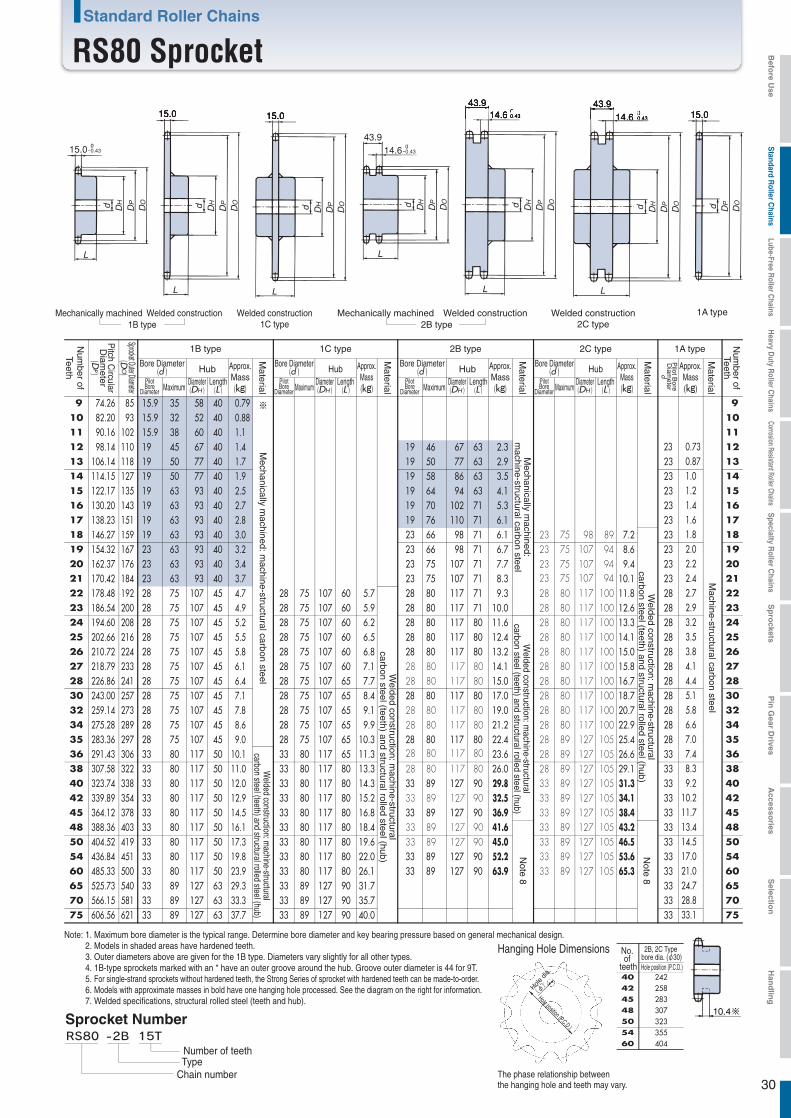
Hole position (P.C.D.)
Hole d
ia.
(φ)
505460
40 24242 25845 28348 307
323355404
Hole position (P.C.D.)
The phase relationship between the hanging hole and teeth may vary.
Hanging Hole Dimensions
30
15.0
15.0
-0.43
15.0 15.0
43.9
43.9
14.6
14.6
-0.43
-0.43
43.914.6-0.43
L
d DH
DP
DO
L L
L
L L
d DH
DP
DO d DH
DP
DO d DH
DP
DO d DH
DP
DO
d dDH
DP
DO
DP
DO
Welded construction1C type
Mechanically machined Welded construction1B type
Mechanically machined Welded construction2B type
Welded construction2C type
1A type
Machine-structural carbon steel
Note 8
Note 8
Welded construction: m
achine-structuralcarbon steel (teeth) and structural rolled steel (hub)
Welded construction: m
achine-structuralcarbon steel (teeth) and structural rolled steel (hub)
Welded construction: m
achine-structuralcarbon steel (teeth) and structural rolled steel (hub)
Welded construction: m
achine-structuralcarbon steel (teeth) and structural rolled steel (hub)
Note: 1. Maximum bore diameter is the typical range. Determine bore diameter and key bearing pressure based on general mechanical design.2. Models in shaded areas have hardened teeth.3. Outer diameters above are given for the 1B type. Diameters vary slightly for all other types.4. 1B-type sprockets marked with an * have an outer groove around the hub. Groove outer diameter is 44 for 9T.5. For single-strand sprockets without hardened teeth, the Strong Series of sprocket with hardened teeth can be made-to-order.6. Models with approximate masses in bold have one hanging hole processed. See the diagram on the right for information.7. Welded specifications, structural rolled steel (teeth and hub).
Sprocket Number
Chain numberTypeNumber of teeth
Mechanically m
achined: machine-structural carbon steel
Mechanically m
achined:m
achine-structural carbon steel
2B type 1A type
Bore Diameter(d ) Hub
PilotBore
Diameter MaximumDiameter(DH )
Length(L )
Approx.Mass
(kg)
Num
ber ofTeeth
Num
ber ofTeeth
Pitch C
ircularD
iameter
(DP)
Sprocket Outer Diameter(D
O)
Material
1B type 1C type
Bore Diameter(d ) Hub
PilotBore
Diameter MaximumDiameter(DH )
Length(L )
Approx.Mass(kg)
Material
Approx.Mass(kg)
Material
Pilot B
oreD
iameter
d
2C type
Bore Diameter(d ) Hub
PilotBore
Diameter MaximumDiameter(DH )
Length(L )
Approx.Mass(kg)
Material
Bore Diameter(d ) Hub
PilotBore
Diameter MaximumDiameter(DH )
Length(L )
Approx.Mass
(kg)
Material
Standard Roller Chains
RS80 Sprocket
50 404.52 419 33 5054 436.84 451 3360 485.33 500 3365 525.73 540 33
75 606.56 621 33
9 74.26 85 15.9 35 58 40 0.790.881.1 1.4 1.7 1.9 2.5 2.7 2.8 3.0 3.2 3.4 3.7 4.7 4.9 5.2 5.5 5.8 6.1 6.4 7.1 7.8 8.6 9.0
10.1 11.0 12.0 12.9 14.5 16.1 17.3 19.8 23.9 29.3 33.3 37.7
※ 910 82.20 93 15.9 32 52 4011 90.16 102 15.9 38 60 4012 98.14 110 19 45 67 40 19 46 67 63 2.3
2.9 3.5 4.1 5.3 6.1 6.1 6.7 7.7 8.3 9.3
10.0 11.6 12.4 13.2 14.1 15.0 17.0 19.0 21.2 22.4 23.6 26.0 29.8 32.5 36.9 41.6 45.0 52.2 63.9
23 0.730.871.0 1.2 1.4 1.6 1.8 2.0 2.2 2.4 2.7 2.9 3.2 3.5 3.8 4.1 4.4 5.1 5.8 6.6 7.0 7.4 8.3 9.2
10.2 11.7 13.4 14.5 17.0 21.0 24.7 28.8 33.1
13 106.14 118 19 50 77 40 19 50 77 63 2314 114.15 127 19 50 77 40 19 58 86 63 23 1415 122.17 135 19 63 93 40 19 64 94 63 2316 130.20 143 19 63 93 40 19 70 102 71 2317 138.23 151 19 63 93 40 19 76 110 71 2318 146.27 159 19 63 93 40 23 66 98 71 2319 154.32 167 23 63 93 40 23 66 98 71 23 1920 162.37 176 23 63 93 40 23 75 107 71 2321 170.42 184 23 63 93 40 23 75 107 71 2322 178.48 192 28 75 107 45 28 75 107 60 5.7
5.9 6.2 6.5 6.8 7.1 7.7 8.4 9.1 9.9
10.3 11.3 13.3 14.3 15.2 16.8 18.4 19.6 22.0 26.1 31.7 35.7 40.0
28 80 117 71 28 80 117 10023 75 107 9423 75 107 9423 75 107 9423 75 98 89 7.2
8.6 9.4
10.1 11.8 12.6 13.3 14.1 15.0 15.8 16.7 18.7 20.7 22.9 25.4 26.6 29.1 31.3 34.1 38.4 43.2 46.5 53.6 65.3
2823 186.54 200 28 75 107 45 28 75 107 60 28 80 117 71 28 80 117 100 2824 194.60 208 28 75 107 45 28 75 107 60 28 80 117 80 28 80 117 100 28 24
25 202.66 216 28 75 107 45 28 75 107 60 28 80 117 80 28 80 117 100 2826 210.72 224 28 75 107 45 28 75 107 60 28 80 117 80
28 80 117 8028 80 117 80
28 80 117 8028 80 117 80
28 80 117 8028 80 117 80
33 89 127 90
33 89 127 9033 89 127 90
28 80 117 10028 80 117 10028 80 117 100
28 80 117 10028 80 117 100
28 89 127 105
2827 218.79 233 28 75 107 45 28 75 107 60 2828 226.86 241 28 75 107 45 28 75 107 65 2830 243.00 257 28 75 107 45 28 75 107 65 28 80 117 80 28 80 117 100 28 3032 259.14 273 28 75 107 45 28 75 107 65 2834 275.28 289 28 75 107 45 28 75 107 65 2835 283.36 297 28 75 107 45 28 75 107 65 28 80 117 80 28 89 127 105 2836 291.43 306 33 80 117 50 33 80 117 65 3338 307.58 322 33 80 117 50 33 80 117 80 33 3840 323.74 338 33 80 117 50 33 80 117 80 33 89 127 90 33 89 127 105
33 89 127 105
28 89 127 105
33 89 127 10533 89 127 105
3342 339.89 354 33 80 117 50 33 80 117 80 3345 364.12 378 33 80 117 50 33 80 117 80 33 89 127 90 33 89 127 105 3348 388.36 403 33 80 117 50 33 80 117 80 33
33 80 117 50 33 80 117 8033 80 117 50 33 80 117 80 33 89 127 90 33 89 127 10533 80 117 50 33 80 117 80 33 89 127 90 33 89 127 10533 89 127 63 33 89 127 90
70 566.15 581 33 89 127 63 33 89 127 90 3333 89 127 63 33 89 127 90
10111213
15161718
20212223
2526
2728
32343536
40424548
5460657075
No. of
teeth
2B, 2C Type bore dia. (φ30)
Befo
re Use
Standard R
oller Chains
Lube-Free Roller C
hainsH
eavy Duty R
oller Chains
Corrosion Resistant Roller ChainsS
pecialty Roller C
hainsS
pro
cketsP
in G
ear Drives
Accesso
riesS
election
Han
dlin
g
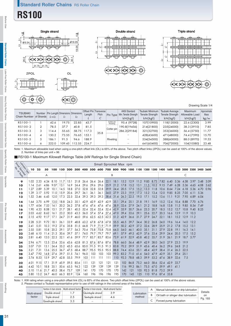
31
L1
CC
L2
L1L1
L
4.0
9.54
4.0
19.05
19.0
5
L1L2
26.0
30.1
31.75 31.75
L1
C
L2
RS100-1 1 42.6 19.75 22.85 43.7
35.8
95.4 {9728} 107{10900} 118{12000} 22.6 {2300} 3.99
RS100-5 5 186.1 91.5 94.6 188.9 534{54500} 588{60000} 88.0 {8970} 19.53
RS100-6 6 222.0 109.45 112.55 224.7 641{65400} 706{72000} 104{10580} 23.48
RS100-2 2 78.5 37.7 40.8 81.5 190.8{19456} 214{21800} 235{24000} 38.3 {3910} 7.85
RS100-3 3 114.4 55.65 58.75 117.3 286.2{29184} 321{32700} 353{36000} 56.4 {5750} 11.77
RS100-4 4 150.2 73.55 76.65 153.1 428{43600} 471{48000} 74.4 {7590} 15.70
A B C
10 25 50 100 150 200 300 400 500 600 700 800 900 1000 1100 1200 1300 1400 1600 1800 2000 2200 2400 2600
1.021.141.271.391.52
1.641.771.902.032.15
2.282.412.552.682.81
2.943.073.213.473.74
4.014.425.105.80
2.332.612.893.173.46
3.754.044.334.624.92
5.215.515.816.106.40
6.717.017.317.928.53
9.1510.111.613.2
4.344.865.395.926.45
6.997.538.088.629.17
9.7210.310.811.412.0
12.513.113.614.815.9
17.118.821.724.7
8.109.0710.111.012.0
13.014.115.116.117.1
18.119.220.221.322.3
23.424.425.527.629.7
31.935.140.546.0
11.713.114.515.917.3
18.820.221.723.224.7
26.127.629.130.632.1
33.635.236.739.742.8
45.950.658.466.3
15.116.918.820.622.5
24.326.228.130.031.9
33.935.837.739.741.6
43.645.547.551.555.5
59.565.575.785.9
21.824.427.029.732.4
35.137.840.543.346.0
48.851.554.357.159.9
62.865.668.474.179.9
85.694.3109124
26.429.632.836.139.3
42.947.652.456.059.6
63.266.870.474.077.7
81.385.088.796.0103
111122141160
26.429.632.836.139.3
42.947.652.457.462.5
67.871.975.879.783.7
87.691.595.5103111
121139170196
26.429.632.836.139.3
42.947.652.457.462.5
67.871.975.879.783.7
87.691.595.5103111
121139170196
22.125.929.934.038.4
42.947.652.457.462.5
67.871.975.879.783.6
87.691.595.5103111
121139170196
18.121.224.427.931.4
35.138.942.947.051.2
55.559.964.569.173.9
78.883.888.899.3110
121139170195
15.217.820.523.326.3
29.432.635.939.442.9
46.550.254.057.961.9
66.070.274.483.292.3
102116142170
12.915.217.519.922.5
25.127.930.733.636.6
39.742.946.149.552.9
56.459.963.671.078.8
86.899.3121145
11.213.115.217.319.5
21.824.126.629.131.7
34.437.240.042.945.8
48.951.955.161.668.3
75.286.1105125
9.8511.513.315.217.1
19.121.223.325.627.9
30.232.635.137.640.2
42.945.648.454.059.9
66.075.592.3110
8.7310.211.813.415.2
16.918.820.722.724.7
26.828.931.133.435.7
38.040.442.947.953.2
58.667.081.897.6
7.829.1510.612.013.6
15.216.818.520.322.1
24.025.927.929.931.9
34.036.238.442.947.6
52.459.973.287.4
6.407.498.649.8511.1
12.413.815.216.618.1
19.621.222.824.426.1
27.929.631.435.138.9
42.949.159.933.8
5.366.287.248.259.31
10.411.512.713.915.2
16.417.819.120.521.9
23.324.826.329.432.6
33.741.1
4.585.366.187.057.95
8.889.8510.811.912.9
14.015.216.317.518.7
19.921.222.525.17.5
3.974.655.366.116.89
7.708.549.4010.311.2
12.213.114.115.25.77
3.484.084.705.366.04
6.767.498.25
3.093.620.96
910111213
1415161718
1920212223
2425262830
32354045
--
-
Triple strandSingle strand Double strand
RS100-1 Maximum Kilowatt Ratings Table (kW Ratings for Single Strand Chain)
Small Sprocket Max rpm
Small Sprocket
Lubrication Type
No. of Teeth
Number of chain strandsNumber of chain strands Multi-strand factorMulti-strand factor1.7 3.92.5 4.63.3 - -
A
B
C
Manual lubrication or drip lubricationDetails
onPg. 193
Oil bath or slinger disc lubrication
Forced pump lubrication
Lubricationmethod
Quintuple strandSextuple strand
Double strandTriple strand
Quadruple strand
Multi-strandfactor
L1+L2 L1 L2
Dimensions Dimensions
L kN{kg f }C kN{kg f } kN{kg f } kN{kg f } kg/m
Drawing Scale 1/4
Riveting
Cotter pinRiveting
Note: 1. Maximum allowable load when using a one-pitch offset link (OL) is 65% of the above. Two pitch offset links (2POL) can be used at 100% of the above values.2. Number of links per unit = 96
Cotter pin
TSUBAKIChain Number
Numberof Strands
Pin LengthTransverse
PitchOffset Pin
Length Pin TypeMaximum
Allowable LoadApproximate
Mass
Note: 1. KW rating when using a one-pitch offset link (OL) is 65% of the above. Two pitch offset links (2POL) can be used at 100% of the above values.2. Please contact a Tsubaki representative prior to use of kW ratings in the colored area of the table.
ANSI StandardMin. Tensile Strength
Tsubaki MinimumTensile Strength
Tsubaki AverageTensile Strength
Standard Roller Chains RS Roller Chain
RS100Befo
re Use
Standard R
oller Chains
Lube-Free Roller C
hainsH
eavy Duty R
oller Chains
Corrosion Resistant Roller ChainsS
pecialty Roller C
hainsS
pro
cketsP
in G
ear Drives
Accesso
riesS
election
Han
dlin
g
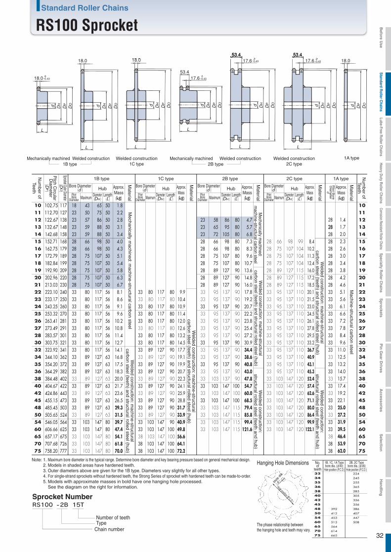
Hole position (P.C.D.)
Hole d
ia.
(φ)
The phase relationship between the hanging hole and teeth may vary.
Hanging Hole Dimensions
32
18.0
18.0
-0.43
18.0 18.0
53.417.6-0.43
53.417.6-0.43
53.417.6-0.43
L
d DH
DP
DO
L
d DH
DP
DO
L
L
Ld DH
DP
DO d DH
DP
DO d DH
DP
DO
L
d dDH
DP
DO
DP
DO
Welded construction1C type
Mechanically machined Welded construction1B type
Mechanically machined Welded construction2B type
Welded construction2C type
1A type
Mechanically m
achined: machine-structural carbon steel
Mechanically m
achined:m
achine-structural carbon steel
Machine-structural carbon steel
Welded construction: m
achine-structuralcarbon steel (teeth) and structural rolled steel (hub)
Welded construction:
structural rolled steel (teeth and hub)
Welded construction:
structural rolled steel (teeth and hub)
Welded construction: m
achine-structuralcarbon steel (teeth) and structural rolled steel (hub)
Welded construction: m
achine-structuralcarbon steel (teeth) and structural rolled steel (hub)
Welded construction: m
achine-structuralcarbon steel (teeth) and structural rolled steel (hub)
Note: 1. Maximum bore diameter is the typical range. Determine bore diameter and key bearing pressure based on general mechanical design.2. Models in shaded areas have hardened teeth.3. Outer diameters above are given for the 1B type. Diameters vary slightly for all other types.4. For single-strand sprockets without hardened teeth, the Strong Series of sprocket with hardened teeth can be made-to-order.5. Models with approximate masses in bold have one hanging hole processed.
See the diagram on the right for information.
Sprocket Number
Chain numberTypeNumber of teeth
2B type 1A type
Bore Diameter(d ) Hub
PilotBore
Diameter MaximumDiameter(DH )
Length(L )
Approx.Mass
(kg)
Num
ber ofTeeth
Num
ber ofTeeth
Pitch C
ircularD
iameter
(DP)
Sprocket Outer Diameter(D
O)
Material
1B type 1C type
Bore Diameter(d ) Hub
PilotBore
Diameter MaximumDiameter(DH )
Length(L )
Approx.Mass(kg)
Material
Approx.Mass(kg)
Material
Pilot B
oreD
iameter
d
2C type
Bore Diameter(d ) Hub
PilotBore
Diameter MaximumDiameter(DH )
Length(L )
Approx.Mass(kg)
Material
Bore Diameter(d ) Hub
PilotBore
Diameter MaximumDiameter(DH )
Length(L )
Approx.Mass
(kg)
Material
Standard Roller Chains
RS100 Sprocket
10 102.75 117 18 43 65 50 1.8 2.2 2.8 3.1 3.4 4.0 4.3 5.1 5.4 5.8 6.3 6.7 8.1 8.6 9.1 9.6
10.2 10.8 11.4 12.7 14.1 16.8 17.5 18.3 20.0 21.7 23.6 26.5 29.3 31.5 39.7 47.4 54.1 61.8 70.0
1011 112.70 127 23 50 75 50 1112 122.67 138 23 57 86 50 23 58 86 80 4.7
5.7 6.8 7.3 8.3 9.6
10.7 13.6 14.8 16.0 17.8 19.2 20.7 22.2 23.8 25.4 27.2 30.9 34.4 38.6 40.8 43.0 47.8 54.7 60.0 68.5 79.4 85.8 99.4
121.6
28 1.4 1.7 2.0 2.3 2.6 3.0 3.4 3.8 4.2 4.6 5.1 5.6 6.1 6.6 7.2 7.8 8.4 9.6
11.0 12.5 13.2 14.0 15.7 17.4 19.2 22.1 25.0 27.2 31.9 39.5 46.4 53.9 62.0
1213 132.67 148 23 59 88 50 23 65 95 80 28 1314 142.68 158 23 59 88 50 23 72 105 80 28 1415 152.71 168 28 66 98 50 28 66 98 80 28 1516 162.75 179 28 66 98 50 28 66 98 80 28 1617 172.79 189 28 75 107 50 28 75 107 80 28 1718 182.84 199 28 75 107 50 28 75 107 80 28 1819 192.90 209 28 75 107 50 28 89 127 90 28 1920 202.96 220 28 75 107 50 28 89 127 90 28 2021 213.03 230 28 75 107 50 28 89 127 90
33 95 137 9033 95 137 90
28 2122 223.10
233.17240250
33 80 117 5633 80 117 56
33 80 117 80 9.9 10.4 10.9 11.4 12.0 12.6 13.2 14.5 17.7 19.1 19.9 20.7 22.3 24.1 25.9 28.8 31.7 33.9 40.9 49.8 56.6 64.1 72.2
33 80 117 8033
28
3322
24 243.25 260 33 80 117 56 33 80 117 80 33 95 137 9033 95 137 9033 95 137 9033 95 137 9033 95 137 90
33 95 137 11033 95 137 11033 95 137 11033 95 137 11033 95 137 110
33 2423 23
25 253.32 270 33 80 117 56 33 80 117 80 33 2526 263.41 281
273.49 29133 80 117 56 33 80 117 80
33 80 117 803333
2627 2728 283.57 301 33 80 117 56
33 80 117 5633 80 117 80 33 28
30 303.75 321 33 80 117 56 33 80 117 80 33 95 137 90 33 95 137 110 33 3032 323.92 341
344.10 36233 80 117 5633 89 127 63
33 89 127 9033 89 127 90
33 89 127 90
3333
33
33
33
32
35 354.20 372 33 89 127 63 33 89 127 90 33 95 137 9033 95 137 9033 137 90
33 95 137 9033 95 137 90
33 95 137 11033 95 137 110
33 95 137 11033 95 137 110
33 3534 34
36 364.29 382384.48 402
33 89 127 6333 89 127 63
33 89 127 90 33 3638 3840 404.67 422
424.86 44333 89 127 6333 89 127 63
33 89 127 9033 89 127 90
33 89 127 90
33 103 147 10033 103
103
147 10033 103 147 12033 103 147 120
33 103 147 12033 40
45 455.15 473 33 89 127 63 33 89 127 90 33 103 147 10033 103 147 11533 103 147 11533 103 147 11533 103 147 115
33 103 147 12033 103 147 12033 103 147 12033 103 147 120
33 4542 42
48 485.45 503505.65 524
33 89 127 6333 89 127 63
33 89 127 90 33 4850 5054 546.05 564 33 103 147 80 33 103 147 90 33 5460 606.66 625
657.17 67533 103 147 8033 103 147 8033 103 147 8033 103 147 80
33 103 147 10038 103 147 100
33 103 147 120 3338
6065 6570 707.68 726 38 103 147 100 38 7075 758.20 777 38 103 147 100 38 75
28 66 98 99 8.4 10.2 11.3 12.4 16.0 17.2 18.5 20.1 21.5 23.0 24.5 26.1 27.8 29.5 33.2 36.7 40.9 43.1 45.3 52.4 57.4 62.6 71.1 80.0 86.4 99.9
122.1
28 75 107 10428 75 107 10428 75 107 10428 89 127 11528 89 127 11528 89 127 11533 95 137 11033 95 137 110
505460
40 305
42 326
45 356
48 386
407
447
508
Hole position (P.C.D.)
38 285
36 365
35 255
34 245
32 224
392
412
453
513
65 564
70 614
75 665
Hole position (P.C.D.)
No.of
teeth
1B, 1C, 1A Typebore dia. (φ40)
2B, 2C Typebore dia. (φ35)
Befo
re Use
Standard R
oller Chains
Lube-Free Roller C
hainsH
eavy Duty R
oller Chains
Corrosion Resistant Roller ChainsS
pecialty Roller C
hainsS
pro
cketsP
in G
ear Drives
Accesso
riesS
election
Han
dlin
g

33
L1
CC
L 2
L1L1
L
4.8
11.11
4.8
22.23
25.4
0
L 1L2
31.2
36.2
38.10 38.10
L1
C
L 2
RS120-1 1 53.8 24.9 28.9 55.0
45.4
137.1{13980} 148{15100} 167 {17000} 30.4 {3100} 5.93
RS120-5 5 235.7 115.85 119.85 239.4 740{75500} 834 {85000} 119{12090} 29.16
RS120-6 6 281.1 138.55 142.55 284.8 888{90600} 1000{102000} 140{14260} 34.96
RS120-2 2 99.2 47.6 51.6 103.2 274.2{27961} 296{30200} 333 {34000} 51.7 {5270} 11.70
RS120-3 3 144.8 70.4 74.4 148.6 411.3{41941} 444{45300} 500 {51000} 76.0 {7750} 17.53
RS120-4 4 190.2 93.1 97.1 194.0 592{60400} 667 {68000} 100{10230} 23.36
A B C
10 25 50 100 150 200 300 400 500 600 700 800 900 1000 1100 1200 1300 1400 1500 1600 1700 1800 1900 2000 2100
1.651.842.042.242.45
2.652.863.063.273.48
3.693.904.114.324.53
4.754.965.175.616.04
6.477.138.249.36
3.754.214.665.125.58
6.056.526.997.467.93
8.418.899.379.8510.3
10.811.311.812.813.8
14.816.318.821.3
7.007.858.709.5610.4
11.312.213.013.914.8
15.716.617.518.419.3
20.221.122.023.925.7
27.630.435.139.8
13.114.616.217.819.4
21.122.724.326.027.6
29.331.032.634.336.0
37.739.441.144.548.0
51.456.765.474.3
18.821.123.425.728.0
30.332.735.037.439.8
42.244.647.049.451.9
54.356.759.264.169.1
74.181.694.3107
24.427.330.333.336.3
39.342.345.448.551.6
54.757.860.964.067.2
70.373.576.783.189.5
96.0106122139
35.139.443.647.952.3
56.661.065.469.874.3
78.783.287.792.296.8
101106110120129
138152176200
41.146.151.056.161.1
66.271.376.583.791.2
98.9107114119125
131137143155167
179197228259
41.146.051.056.161.1
66.271.376.583.791.2
98.9107115123132
140146152165178
191210242286
32.237.743.549.655.9
62.569.376.483.791.2
98.9107115123132
140146152165178
191210242286
25.630.034.639.444.4
49.655.060.666.472.3
78.484.791.297.7104
111118126140156
171196240286
20.924.528.332.236.3
40.645.049.654.359.2
64.269.374.680.085.5
91.296.9103115127
140161196234
17.520.523.727.030.5
34.037.741.645.549.6
53.858.162.567.071.7
76.481.286.196.3107
118135164196
15.017.520.223.126.0
29.132.235.538.942.4
45.949.653.457.261.2
65.269.373.582.291.2
100115140167
13.015.217.520.022.5
25.227.930.833.736.7
39.843.046.349.653.0
56.560.163.771.279.0
87.099.6122145
11.413.315.417.519.8
22.124.527.029.632.2
35.037.740.643.546.6
49.652.855.962.569.3
76.487.4107127
10.111.813.715.617.5
19.621.724.026.228.6
31.033.536.038.641.3
44.046.849.655.561.5
67.877.594.759.7
9.0410.612.213.915.7
17.519.521.423.525.6
27.730.032.234.636.9
39.441.944.449.655.0
60.669.344.4
8.159.5511.012.614.2
15.817.519.321.223.1
25.027.029.131.233.3
35.537.740.044.749.6
54.735.6
7.408.6710.011.412.8
14.415.917.519.220.9
22.724.526.428.330.2
32.234.336.340.631.6
6.767.919.1310.411.7
13.114.516.017.519.1
20.722.424.125.827.6
29.430.819.8
6.207.268.389.5510.8
12.013.314.716.117.5
19.020.522.112.4
5.726.707.738.819.93
11.112.313.614.88.43
5.306.207.168.159.19
6.67
4.925.76
910111213
1415161718
1920212223
2425262830
32354045
--
-
Triple strandSingle strand Double strand
RS120-1 Maximum Kilowatt Ratings Table (kW Ratings for Single Strand Chain)
Small Sprocket Max rpm
Small Sprocket
Lubrication Type
No. of Teeth
Number of chain strandsNumber of chain strands Multi-strand factorMulti-strand factor1.7 3.92.5 4.63.3 - -
A
B
C
Manual lubrication or drip lubricationDetails
onPg. 193
Oil bath or slinger disc lubrication
Forced pump lubrication
Lubricationmethod
Quintuple strandSextuple strand
Double strandTriple strand
Quadruple strand
Multi-strandfactor
L1+L2 L1 L2
Dimensions Dimensions
L kN{kg f }C kN{kg f } kN{kg f } kN{kg f } kg/m
Drawing Scale 1/4.8
Riveting
Note: 1. Maximum allowable load when using a one-pitch offset link (OL) is 65% of the above. Two pitch offset links (2POL) can be used at 100% of the above values.2. Number of links per unit = 80
Cotter pinRiveting
Cotter pin
TSUBAKIChain Number
Numberof Strands
Pin LengthTransverse
PitchOffset Pin
Length Pin TypeMaximum
Allowable LoadApproximate
Mass
Note: 1. KW rating when using a one-pitch offset link (OL) is 65% of the above. Two pitch offset links (2POL) can be used at 100% of the above values.2. Please contact a Tsubaki representative prior to use of kW ratings in the colored area of the table.
ANSI StandardMin. Tensile Strength
Tsubaki MinimumTensile Strength
Tsubaki AverageTensile Strength
Standard Roller Chains RS Roller Chain
RS120Befo
re Use
Standard R
oller Chains
Lube-Free Roller C
hainsH
eavy Duty R
oller Chains
Corrosion Resistant Roller ChainsS
pecialty Roller C
hainsS
pro
cketsP
in G
ear Drives
Accesso
riesS
election
Han
dlin
g
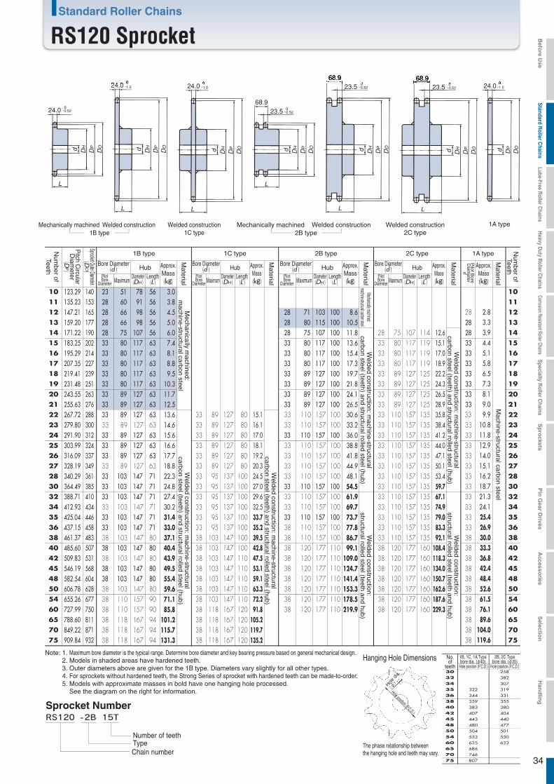
The phase relationship between the hanging hole and teeth may vary.
Hanging Hole Dimensions
Hole position (P.C.D.)
Hole d
ia.
(φ)
50
5460
40 38042 40445 44048 477
501550623
Hole position (P.C.D.)
38 355
36 331
35 319
34 307
32 382
30 258
480443407383359344322
504553625
65 68670 74675 807
Hole position (P.C.D.)
34
24.0
24.0
-0.52
24.0 24.0
68.923.5 -0.52
23.5 -0.52
68.923.5 -0.52
68.9
L
d DH
DP
DO
L
d DH
DP
DO
L
L
d DH
DP
DO d DH
DP
DO
L
d DH
DP
DO
L
d dDH
DP
DO
DP
DO
0-1.0
0-1.0
0-1.0
Welded construction1C type
Mechanically machined Welded construction1B type
Mechanically machined Welded construction2B type
Welded construction2C type
1A type
Mechanically m
achined:m
achine-structural carbon steel
Mechanically machined:machine-structural carbon steel
Machine-structural carbon steel
Welded construction: m
achine-structuralcarbon steel (teeth) and structural rolled steel (hub)
Welded construction: m
achine-structuralcarbon steel (teeth) and structural rolled steel (hub)
Welded construction: m
achine-structuralcarbon steel (teeth) and structural rolled steel (hub)
Welded construction: m
achine-structuralcarbon steel (teeth) and structural rolled steel (hub)
Welded construction:
structural rolled steel (teeth and hub)
Welded construction:
structural rolled steel (teeth and hub)
Note: 1. Maximum bore diameter is the typical range. Determine bore diameter and key bearing pressure based on general mechanical design.2. Models in shaded areas have hardened teeth.3. Outer diameters above are given for the 1B type. Diameters vary slightly for all other types.4. For sprockets without hardened teeth, the Strong Series of sprocket with hardened teeth can be made-to-order.5. Models with approximate masses in bold have one hanging hole processed.
See the diagram on the right for information.
Sprocket Number
Chain numberTypeNumber of teeth
2B type 1A type
Bore Diameter(d ) Hub
PilotBore
Diameter MaximumDiameter(DH )
Length(L )
Approx.Mass
(kg)
Num
ber ofTeeth
Num
ber ofTeeth
Pitch C
ircularD
iameter
(DP)
Sprocket Outer Diameter(D
O)
Material
1B type 1C type
Bore Diameter(d ) Hub
PilotBore
Diameter MaximumDiameter(DH )
Length(L )
Approx.Mass(kg)
Material
Approx.Mass(kg)
Material
Pilot B
oreD
iameter
d
2C type
Bore Diameter(d ) Hub
PilotBore
Diameter MaximumDiameter(DH )
Length(L )
Approx.Mass(kg)
Material
Bore Diameter(d ) Hub
PilotBore
Diameter MaximumDiameter(DH )
Length(L )
Approx.Mass
(kg)
Material
Standard Roller Chains
RS120 Sprocket
10 123.29 140 23 51 78 56 3.0 3.8 4.5 5.0 6.0 7.4 8.1 8.8 9.5
10.3 11.7 12.5 13.6 14.6 15.6 16.6 17.7 18.8 22.3 24.8 27.4 30.2 31.4 33.0 37.1 40.4 43.9 49.5 55.4 59.6 71.1 85.8
101.2 115.7 131.3
1011 135.23 153 28 60 91 56 1112 147.21 165 28 66 98 56 28 71 103 100 8.6
10.5 11.8 13.6 15.4 17.3 19.7 21.8 24.1 26.5 30.6 33.2 36.0 38.8 41.8 44.9 48.1 54.5 61.9 69.7 73.7 77.8 86.7 99.1
109.0 124.7 141.4 153.3 178.5 219.9
28 2.8 3.3 3.9 4.4 5.1 5.8 6.5 7.3 8.1 9.0 9.9
10.8 11.8 12.9 14.0 15.1 16.2 18.7 21.3 24.1 25.4 26.9 30.0 33.3 36.8 42.4 48.4 52.6 61.5 76.1 89.6
104.0 119.6
1213 159.20 177 28 66 98 56 28 80 115 100 28 1314 171.22 190 28 75 107 56 28 75 107 100 28 1415 183.25 202 33 80 117 63 33 80 117 100 33 1516 195.29 214 33 80 117 63 33 80 117 100 33 1617 207.35 227 33 80 117 63 33 80 117 100 33 1718 219.41 239 33 80 117 63 33 89 127 100 33 1819 231.48 251 33 80 117 63 33 89 127 100 33 1920 243.55 263 33 89 127 63 33 89 127 100 33 2021 255.63 276 33 89 127 63 33 89 127 100
33 157 10033 21
22 267.72 288279.80 300
33 89 127 6333 89 127 63
33 89 127 80 15.1 16.1 17.0 18.1 19.2 20.3 24.5 27.0 29.6 32.5 33.7 35.2 39.5 42.8 47.5 53.1 59.1 63.3 72.2 91.8
105.2 119.7 135.2
33 89 127 8033 22
23 2324 291.90 312 33 89 127 63 33 89 127 80 33 110
11033 157 100110
157 10033 110 157 10033 110 157 10033 110 157 10033 110 157 100
33 110110110
157 135
28 75 107 114 12.6 15.1 17.0 18.9 22.2 24.3 26.5 28.9 35.8 38.4 41.2 44.0 47.1 50.1 53.4 59.7 67.1 74.9 79.0 83.3 92.1
108.4 118.3 134.0 150.7 162.6 187.6 229.3
33 80 117 11933 80 117 11933 80 117 11933 89 127 12533 89 127 12533 89 127 12533 89 127 12533 157 13533 157 135
3333
2425 303.99 324 33 89 127 63 33 89 127 80 33 2526 316.09 337
328.19 34933 89 127 6333 89 127 63
33 89 127 8033 89 127 80
3333
2627 2728 340.29 361 33 103 147 71 33 95 137 100 33 2830 364.49 385 33 103 147 71 33 95 137 100 33 110 157 100
33 110 157 10033 110 157 100
33 110 157 13533 110 157 13533 110 157 13533 110 157 13533 110 157 135
33 3032 388.71 410
412.93 43433 103 147 7133 103 147 71
33 95 137 10033 95 137 100
3333
3234 3435 425.04 446 33 103 147 71 33 95 137 100 33 110 157 100
38 110 157 10038 110 157 10038 120 177 11038 120 177 11038 120 177 11038 120 177 11038 120 177 11038 120 177 11038 120 177 110
33 110 157 13533 110 157 13533 110 157 135
33 110 157 13533 110 157 135
33 3536 437.15 458
461.37 48333 103 147 71 33 95 137 100 33
3836
38 3840 485.60 507
509.83 53138 103 147 8038 103 147 80
38 103 147 8038 103 147 10038 103 147 110
38 103 147 10038 120 177 16038 120 177 160
38 120 177 16038 120 177 16038 120 177 160
3838
4042 4245 546.19 568 38 103 147 80 38 103 147 110 38 120 177 160 38 4548 582.54 604
606.78 62838 103 147 8038 103 147 8038 110 157 9038 110 157 9038 118 167 9438 118 167 9438 118 167 94
38 103 147 11038 103 147 110
3838
4850 5054 655.26 677 38 103 147 110 38 54
60 727.99 750788.60 811
38 118 167 12038 118 167 120
38 120 177 160 3838
6065 6570 849.22 871 38 118 167 120 38 7075 909.84 932 38 118 167 120 38 75
No.of
teeth
1B, 1C, 1A Typebore dia. (φ40)
2B, 2C Typebore dia. (φ35)
Befo
re Use
Standard R
oller Chains
Lube-Free Roller C
hainsH
eavy Duty R
oller Chains
Corrosion Resistant Roller ChainsS
pecialty Roller C
hainsS
pro
cketsP
in G
ear Drives
Accesso
riesS
election
Han
dlin
g
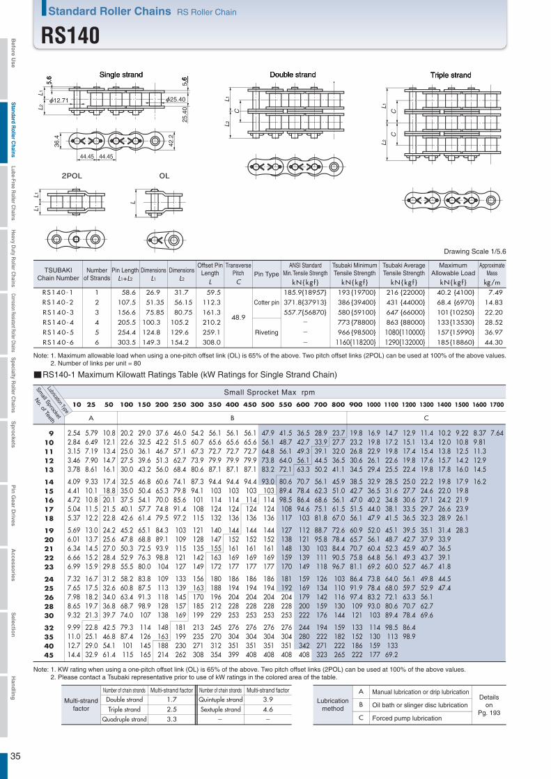
35
L1
CC
L2
L1L1
L
5.6
12.71
5.6
25.40
25.4
0
L1L2
36.4
42.2
44.45 44.45
L1
C
L2
RS140-1 1 58.6 26.9 31.7 59.5
48.9
185.9{18957} 193 {19700} 216 {22000} 40.2 {4100} 7.49
RS140-5 5 254.4 124.8 129.6 259.1 966 {98500} 1080{110000} 157{15990} 36.97
RS140-6 6 303.5 149.3 154.2 308.0 1160{118200} 1290{132000} 185{18860} 44.30
RS140-2 2 107.5 51.35 56.15 112.3 371.8{37913} 386 {39400} 431 {44000} 68.4 {6970} 14.83
RS140-3 3 156.6 75.85 80.75 161.3 557.7{56870} 580 {59100} 647 {66000} 101{10250} 22.20
RS140-4 4 205.5 100.3 105.2 210.2 773 {78800} 863 {88000} 133{13530} 28.52
A B C
10 25 50 100 150 200 250 300 350 400 450 500 550 600 700 800 900 1000 1100 1200 1300 1400 1500 1600 1700
2.542.843.153.463.78
4.094.414.725.045.37
5.696.016.346.666.99
7.327.657.988.659.32
9.9911.012.714.4
5.796.497.197.908.61
9.3310.110.811.512.2
13.013.714.515.215.9
16.717.518.219.721.3
22.825.129.032.9
10.812.113.414.716.1
17.418.820.121.522.8
24.225.627.028.429.8
31.232.634.036.839.7
42.546.854.161.4
20.222.625.027.530.0
32.535.037.540.142.6
45.247.850.352.955.5
58.260.863.468.774.0
79.387.4101115
29.032.536.139.643.2
46.850.454.157.761.4
65.168.872.576.380.0
83.887.591.398.9107
114126145165
37.642.246.751.356.0
60.665.370.074.879.5
84.389.193.998.8104
109113118128138
148163188214
46.051.557.162.768.4
74.179.885.691.497.2
103109115121127
133139145157169
181199230262
54.260.767.373.980.6
87.394.1101108115
121128135142149
156163170185199
213235271308
56.165.672.779.987.1
94.4103114124132
140147155163172
180188196212229
245270312354
56.165.672.779.987.1
94.4103114124136
144152161169177
186194204228253
276304351399
56.165.672.779.987.1
94.4103114124136
144152161169177
186194204228253
276304351408
47.956.164.873.883.2
93.0103114124136
144152161169177
186194204228253
276304351408
41.548.756.164.072.1
80.689.498.5108117
127138148159170
181192204228253
276304351408
36.542.749.356.163.3
70.778.486.494.6103
112121130139149
159169179200222
244280342408
28.933.939.144.550.2
56.162.368.675.181.8
88.795.8103111118
126134142159176
194222271323
23.727.732.036.541.1
45.951.056.161.567.0
72.678.484.490.596.7
103110116130144
159182222265
19.823.226.830.634.5
38.542.747.051.556.1
60.965.770.775.881.1
86.491.997.4109121
133152186222
16.919.822.926.129.4
32.936.540.244.047.9
52.056.160.464.869.2
73.878.483.293.0103
114130159177
14.717.219.822.625.5
28.531.634.838.141.5
45.148.752.356.160.0
64.068.072.180.689.4
98.511313369.2
12.915.117.419.822.4
25.027.730.633.536.5
39.542.745.949.352.7
56.159.763.370.778.4
86.498.9
11.413.415.417.619.8
22.224.627.129.732.3
35.137.940.743.746.7
49.852.956.162.769.6
10.212.013.815.717.8
19.822.024.226.628.9
31.433.936.539.141.8
44.547.4
9.2210.812.514.216.0
17.919.821.923.926.1
28.3
8.379.8111.312.914.5
16.2
7.64910111213
1415161718
1920212223
2425262830
32354045
-
-
-
Triple strandSingle strand Double strand
RS140-1 Maximum Kilowatt Ratings Table (kW Ratings for Single Strand Chain)
Small Sprocket Max rpm
Small Sprocket
Lubrication Type
No. of Teeth
Number of chain strandsNumber of chain strands Multi-strand factorMulti-strand factor1.7 3.92.5 4.63.3 - -
A
B
C
Manual lubrication or drip lubricationDetails
onPg. 193
Oil bath or slinger disc lubrication
Forced pump lubrication
Lubricationmethod
Quintuple strandSextuple strand
Double strandTriple strand
Quadruple strand
Multi-strandfactor
L1+L2 L1 L2
Dimensions Dimensions
L kN{kg f }C kN{kg f } kN{kg f } kN{kg f } kg/m
Drawing Scale 1/5.6
Riveting
Note: 1. Maximum allowable load when using a one-pitch offset link (OL) is 65% of the above. Two pitch offset links (2POL) can be used at 100% of the above values.2. Number of links per unit = 80
Cotter pin
TSUBAKIChain Number
Numberof Strands
Pin LengthTransverse
PitchOffset Pin
Length Pin TypeMaximum
Allowable LoadApproximate
Mass
Note: 1. KW rating when using a one-pitch offset link (OL) is 65% of the above. Two pitch offset links (2POL) can be used at 100% of the above values.2. Please contact a Tsubaki representative prior to use of kW ratings in the colored area of the table.
ANSI StandardMin. Tensile Strength
Tsubaki MinimumTensile Strength
Tsubaki AverageTensile Strength
Standard Roller Chains RS Roller Chain
RS140Befo
re Use
Standard R
oller Chains
Lube-Free Roller C
hainsH
eavy Duty R
oller Chains
Corrosion Resistant Roller ChainsS
pecialty Roller C
hainsS
pro
cketsP
in G
ear Drives
Accesso
riesS
election
Han
dlin
g

36
24.0
24.0
-0.52
24.0 24.0
L
L
d DH
DP
DO d DH
DP
DO
L
d dDH
DP
DO
DP
DO
0-1.0
0-1.0
0-1.0
Welded construction1C type
Mechanically machined Welded construction1B type
1A type
Mechanically m
achined:m
achine-structural carbon steel
Machine-structural carbon steel
Welded construction: m
achine-structuralcarbon steel (teeth) and structural rolled steel (hub)
Welded construction: m
achine-structuralcarbon steel (teeth) and structural rolled steel (hub)
Note: 1. Maximum bore diameter is the typical range. Determine bore diameter and key bearing pressure based on general mechanical design.2. Models in shaded areas have hardened teeth.3. For sprockets without hardened teeth, the Strong Series of sprocket with hardened teeth can be made-to-order.4. Models with approximate masses in bold have one hanging hole processed.
See the diagram on the right for information.
Sprocket Number
Chain numberTypeNumber of teeth
Num
ber ofTeeth
1C type
Approx.Mass(kg)
Material
Pilot BoreD
iameter
(d)
1A type
Num
ber ofTeeth
Pitch C
ircularD
iameter
(DP)
Sprocket Outer Diameter(D
O)
Bore Diameter(d ) Hub
Pilot BoreDiameter Maximum Diameter
(DH )Length
(L )
Approx.Mass
(kg)M
aterial
1B type
Bore Diameter(d ) Hub
Pilot BoreDiameter Maximum Diameter
(DH )Length
(L )
Approx.Mass
(kg)
Material
Standard Roller Chains
RS140 Sprocket
10 143.84 163 28 60 91 56 4.1 5.1 6.3 7.5 8.9 9.7
10.6 11.5 12.5 15.1 16.2 17.4 19.6 21.0 22.3 24.7 26.0 27.6 29.2 32.6 36.3 40.1 44.6 46.7 51.1 55.6 62.3 70.0 78.3 84.0 96.7
116.6
28 1011 157.77 178 33 73 106 56 33 1112 171.74 193 33 80 117 56 33 1213 185.74 207 33 80 117 63 33 1314 199.76 221 33 89 127 63 33 1415 213.79 236 33 89 127 63 33 1516 227.84 250 33 89 127 63 33 1617 241.91 264 33 89 127 63 33 1718 255.98 279 33 89 127 63 33 1819 270.06 293 33 95 137 71 33 1920 284.14 307 33 95 137 71 33 2021 298.24 322 33 95 137 71 33 2122 312.34 336
326.44 3503333
147147147
7171
33 147 11533 147 115
3333
2223 2324 340.54 364 33 71 33 147 115 33 2425 354.65 379 38 103
103103103
147 80 38 103103103103
147 115 38 2526 368.77 393
382.88 407397.00 421
383838
3838
103103103
147147147
147147
808080
38 103 147 11538 103 147 11538 103 147 115
383838
2627 2728 2830 425.24 450
453.49 478481.75 506
38 103103103
147 808080
38 103 147 115 383838
3838
3032 3234 3435 495.88 521
510.01 535538.27 563
383838
383838383838
110110110
118118118118118118
157157157
909090
38 110 157 125 38 3536 3638 3840 566.54 591
594.81 62038 110 157
167167167167167167
90949494949494
38 118 167 130 3838
3838
4042 4245 637.22 662 38 118 167 130 38 4548 679.63 705
707.91 733764.47 790
38 118 167 13038 118 167 130
38 118 167 130
38 110 157 12538 110 157 125
38 103 147 11538 103 147 115
38 4850 5054 5460 849.32 875 38 118 167 155
38 118 167 13038 60
505460
40424548
38363534
291
32
277263
30
282726
461432404390376348319
489531574602659743
1B, 1C, 1A Typebore dia. (φ40)
Hole position (P.C.D.)
2.6 3.2 3.8 4.5 5.3 6.1 7.0 7.9 9.0
10.0 11.1 12.3 13.6 14.8 16.2 17.6 18.8 20.3 21.9 25.3 28.9 32.7 34.7 36.8 41.1 45.6 50.4 58.0 66.1 71.8 84.0
103.9
25.1 26.4 27.7 28.9 30.1 31.7 33.2 36.6 40.2 44.0 49.2 51.2 55.5 62.9 67.6 75.2 83.4 89.1
101.2 125.2
The phase relationship between the hanging hole and teeth may vary.
Hanging Hole Dimensions
Hole position (P.C.D.)
Hole d
ia.
(φ)
No.of
teeth
Befo
re Use
Standard R
oller Chains
Lube-Free Roller C
hainsH
eavy Duty R
oller Chains
Corrosion Resistant Roller ChainsS
pecialty Roller C
hainsS
pro
cketsP
in G
ear Drives
Accesso
riesS
election
Han
dlin
g
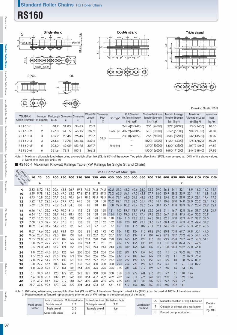
37
L1
CC
L 2
L1L1
L
6.4
14.29
6.4
28.58
31.7
5
L1L2
41.6
48.2
50.80 50.80
L1
C
L2
RS160-1 1 68.7 31.85 36.85 70.2
58.5
244.6{24942} 255 {26000} 279 {28500} 53.0{5400} 10.10
RS160-5 5 303.0 149.05 153.95 307.7 1270{130000} 1400{142500} 207{21060} 49.89
RS160-6 6 361.6 178.3 183.3 366.2 1530{156000} 1680{171000} 244{24840} 59.93
RS160-2 2 127.3 61.15 66.15 132.2 489.2{49885} 510 {52000} 559 {57000} 90.0{9180} 20.04
RS160-3 3 185.9 90.45 95.45 190.7 733.8{74827} 765 {78000} 838 {85500} 132{13500} 30.02
RS160-4 4 244.4 119.75 124.65 249.2 1020{104000} 1120{114000} 175{17820} 40.06
A B C
10 25 50 100 150 200 250 300 350 400 450 500 550 600 650 700 750 800 850 900 1000 1100 1200 1300
3.824.294.755.225.69
6.166.647.127.608.09
8.579.069.5510.010.5
11.011.512.013.014.0
15.116.619.221.7
8.729.7810.811.913.0
14.115.116.217.318.4
19.620.721.822.924.0
25.226.327.429.732.0
34.337.843.749.6
16.318.220.222.224.2
26.228.330.332.434.4
36.538.640.642.744.8
47.049.151.255.559.8
64.170.681.592.6
30.434.037.741.445.2
49.052.756.660.464.2
68.172.075.979.883.7
87.691.695.5103112
120132152173
43.849.054.359.765.1
70.576.081.587.092.5
98.1104109115121
126132138149161
172190219249
56.763.570.477.384.3
91.498.4106113120
127134142149156
164171178193208
223246284322
69.377.686.194.5103
112120129138146
155164173182191
200209218236254
273300347394
74.587.398.5108118
128138148162173
183193204214225
236246257278300
321354409464
74.587.398.5108118
128138148162177
192207220231243
254266277300325
358407470533
74.587.398.5108118
128138148162177
192207220231243
254266277300325
358409485551
62.573.284.496.2108
121134148162177
192207220231243
254266277300325
358409485551
53.362.572.182.192.6
103115126138151
164177190204218
232247262293325
358409485551
46.254.162.571.280.2
89.799.5110120131
142153165177189
201214227254281
310354433517
40.647.554.862.570.4
78.787.396.2105115
124134145155166
177188199223247
272311380454
36.042.148.655.462.5
69.877.485.393.4102
110119128138147
157167177197219
241276337402
32.237.743.549.655.9
62.569.376.383.691.1
98.8107115123132
140149158177196
216247302360
29.034.039.244.750.4
56.362.568.875.482.1
89.096.2103111119
126134143159177
195223272312
26.430.935.640.645.7
51.156.762.568.474.5
80.887.393.9101108
115122129145160
177202247260
24.128.232.537.041.8
46.751.857.062.568.1
73.879.785.892.098.3
105111118132146
161185225202
22.125.929.834.038.3
42.847.552.357.362.5
67.773.278.784.490.2
96.2102108121134
148169192141
18.922.125.529.032.7
36.640.644.748.953.3
57.862.567.272.177.0
82.187.392.6103115
126134
16.319.122.125.228.4
31.735.238.742.446.2
50.154.158.362.566.8
71.275.480.289.7
14.316.819.422.124.9
27.830.934.037.240.6
44.047.551.1
12.714.917.219.622.1
24.7
910111213
1415161718
1920212223
2425262830
32354045
-
-
-
Triple strandSingle strand Double strand
RS160-1 Maximum Kilowatt Ratings Table (kW Ratings for Single Strand Chain)
Small Sprocket Max rpm
Small Sprocket
Lubrication Type
No. of Teeth
Number of chain strandsNumber of chain strands Multi-strand factorMulti-strand factor1.7 3.92.5 4.63.3 - -
A
B
C
Manual lubrication or drip lubricationDetails
onPg. 193
Oil bath or slinger disc lubrication
Forced pump lubrication
Lubricationmethod
Quintuple strandSextuple strand
Double strandTriple strand
Quadruple strand
Multi-strandfactor
L1+L2 L1 L2
Dimensions Dimensions
L kN{kg f }C kN{kg f } kN{kg f } kN{kg f } kg/m
Drawing Scale 1/6.5
Riveting
Cotter pin
Note: 1. Maximum allowable load when using a one-pitch offset link (OL) is 65% of the above. Two pitch offset links (2POL) can be used at 100% of the above values.2. Number of links per unit = 60
TSUBAKIChain Number
Numberof Strands
Pin LengthTransverse
PitchOffset Pin
Length Pin TypeMaximum
Allowable LoadApproximate
Mass
Note: 1. KW rating when using a one-pitch offset link (OL) is 65% of the above. Two pitch offset links (2POL) can be used at 100% of the above values.2. Please contact a Tsubaki representative prior to use of kW ratings in the colored area of the table.
ANSI StandardMin. Tensile Strength
Tsubaki MinimumTensile Strength
Tsubaki AverageTensile Strength
Standard Roller Chains RS Roller Chain
RS160Befo
re Use
Standard R
oller Chains
Lube-Free Roller C
hainsH
eavy Duty R
oller Chains
Corrosion Resistant Roller ChainsS
pecialty Roller C
hainsS
pro
cketsP
in G
ear Drives
Accesso
riesS
election
Han
dlin
g
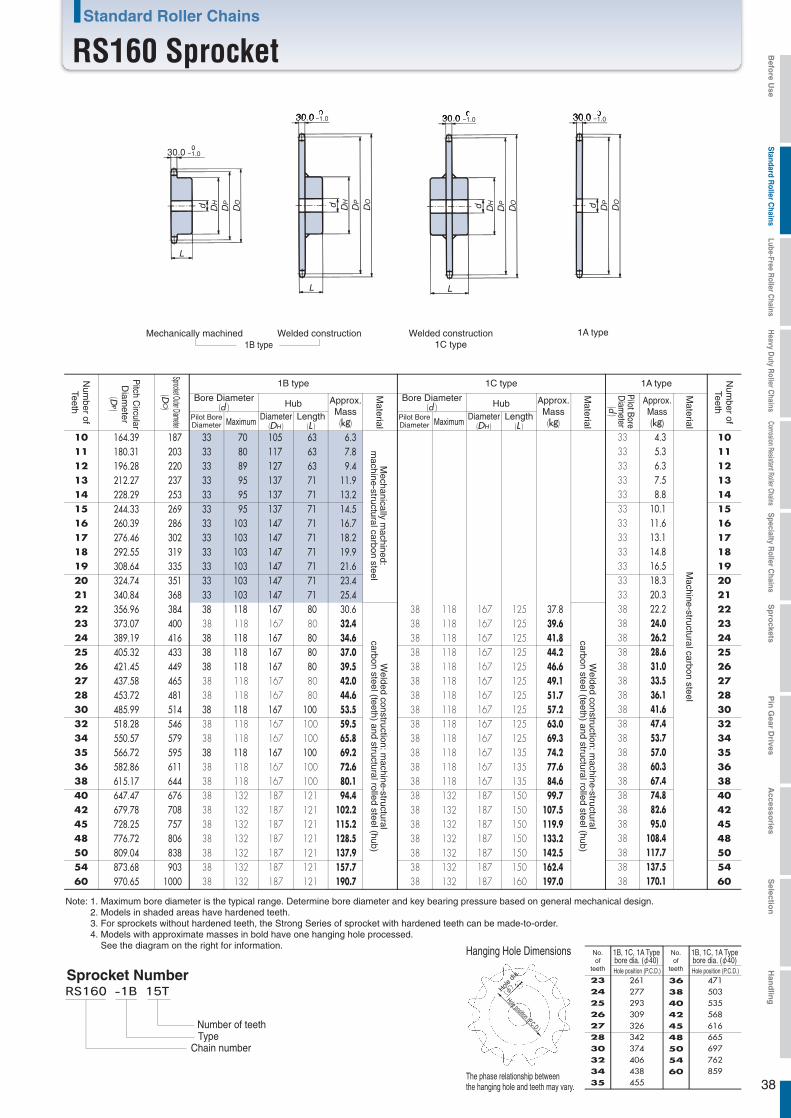
The phase relationship between the hanging hole and teeth may vary.
Hanging Hole Dimensions
Hole position (P.C.D.)
Hole d
ia.
(φ)
38
30.0 -1.0
30.0 30.0 30.0
L
d DH
DP
DO
L
d DH
DP
DO
L
d dDH
DP
DO
DP
DO
Welded construction1C type
Mechanically machined Welded construction1B type
1A type
Mechanically m
achined:m
achine-structural carbon steel
Machine-structural carbon steel
Welded construction: m
achine-structuralcarbon steel (teeth) and structural rolled steel (hub)
Welded construction: m
achine-structuralcarbon steel (teeth) and structural rolled steel (hub)
Note: 1. Maximum bore diameter is the typical range. Determine bore diameter and key bearing pressure based on general mechanical design.2. Models in shaded areas have hardened teeth.3. For sprockets without hardened teeth, the Strong Series of sprocket with hardened teeth can be made-to-order.4. Models with approximate masses in bold have one hanging hole processed.
See the diagram on the right for information.
Sprocket Number
Chain numberTypeNumber of teeth
Num
ber ofTeeth
1C type
Approx.Mass(kg)
Material
Pilot BoreD
iameter
(d)
1A type
Num
ber ofTeeth
Pitch C
ircularD
iameter
(DP)
Sprocket Outer Diameter(D
O)
Bore Diameter(d ) Hub
Pilot BoreDiameter Maximum Diameter
(DH )Length
(L )
Approx.Mass
(kg)M
aterial
1B type
Bore Diameter(d ) Hub
Pilot BoreDiameter Maximum Diameter
(DH )Length
(L )
Approx.Mass
(kg)
Material
Standard Roller Chains
RS160 Sprocket
10 164.39 187 33 70 105 63 6.3 7.8 9.4
11.9 13.2 14.5 16.7 18.2 19.9 21.6 23.4 25.4 30.6 32.4 34.6 37.0 39.5 42.0 44.6 53.5 59.5 65.8 69.2 72.6 80.1 94.4
102.2 115.2 128.5 137.9 157.7 190.7
33 4.3 5.3 6.3 7.5 8.8
10.1 11.6 13.1 14.8 16.5 18.3 20.3 22.2 24.0 26.2 28.6 31.0 33.5 36.1 41.6 47.4 53.7 57.0 60.3 67.4 74.8 82.6 95.0
108.4 117.7 137.5 170.1
1011 180.31 203 33 80 117 63 33 1112 196.28 220 33 89 127 63 33 1213 212.27 237 33 95 137 71 33 1314 228.29 253 33 95 137 71 33 1415 244.33 269 33 95 137 71 33 1516 260.39 286 33 103 147 71 33 1617 276.46 302 33 103 147 71 33 1718 292.55 319 33 103 147 71 33 1819 308.64 335 33 103 147 71 33 1920 324.74 351 33 103 147 71 33 2021 340.84 368 33 103 147 71 33 2122 356.96 384
373.07 4003838
118118
167167
8080
3838
118118
118118
118118
118118
132
167167
167167
167167
167
125125
37.8 39.6 41.8 44.2 46.6 49.1 51.7 57.2 63.0 69.3 74.2 77.6 84.6 99.7
107.5 119.9 133.2 142.5 162.4 197.0
3838
2223 2324 389.19 416 38 118 167 80 38 118 167 125 38 2425 405.32 433 38 118 167 80 38 118 167 125 38 2526 421.45 449
437.58 465453.72 481
383838
3838
383838383838383838
118118118
118118
118118132132132132132132132
167167167
167167
167167187187187187187187187
808080
383838
3838
3838
38
118 167 125125125
383838
2627 2728 2830 485.99 514 38 118 167 100
100100
38 118 167 125125125
383838
3032 518.28 546
550.57 57932
34 3435 566.72 595
582.86 611615.17 644
38 118 167 100100100121121121121121121121
38 118 167 135135135
383838
3536 3638 3840 647.47 676
679.78 70838 132 187
187
167150150
3838
4042 4245 728.25 757 38 132 187 150 38 45
60 970.65 1000 38 132 187 160 38 60
48 776.72 806809.04 838873.68 903
383838
132132132
187187187
150150150
383838
4850 5054 54
309326342374406438455
293277261
3534323028272625
2324
471503535568616665697762859
505460
40424548
3836
1B, 1C, 1A Typebore dia. (φ40)
1B, 1C, 1A Typebore dia. (φ40)
No.of
teeth
No.of
teethHole position (P.C.D.) Hole position (P.C.D.)
-1.0 -1.0 -1.0
Befo
re Use
Standard R
oller Chains
Lube-Free Roller C
hainsH
eavy Duty R
oller Chains
Corrosion Resistant Roller ChainsS
pecialty Roller C
hainsS
pro
cketsP
in G
ear Drives
Accesso
riesS
election
Han
dlin
g
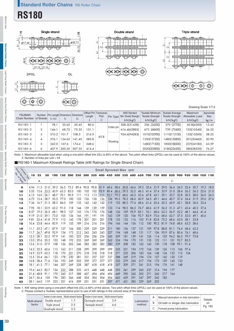
L1
CC
L2
L1L1
L
7.15
17.46
7.15
35.71
35.7
2
L1L2
46.8
54.2
57.15 57.15
L1
C
L 2
RS180-1 1 78.1 35.65 42.45 80.6
65.8
308.2{31428} 336 {34300} 370 {37700} 60.8{6200} 13.45
RS180-5 5 342.0 167.6 174.4 348.6 - 1680{171500} 1850{188500} 237{24180} 63.59
RS180-6 6 407.9 200.55 207.35 414.4 - 2020{205800} 2180{226200} 280{28520} 76.27
RS180-2 2 144.1 68.75 75.35 151.1 616.4{62885} 673 {68600} 739 {75400} 103{10540} 26.52
RS180-3 3 210.2 101.7 108.5 216.9 924.6{94283} 1010{102900} 1110{113100} 152{15500} 38.22
RS180-4 4 276.1 134.65 141.45 282.8 - 1350{137200} 1480{150800} 201{20460} 50.90
A B C
10 25 50 100 150 200 250 300 350 400 450 500 550 600 650 700 750 800 850 900 950 1000 1050 1100
4.945.536.136.737.34
7.958.579.199.8110.4
11.111.712.313.013.6
14.214.915.516.818.1
19.421.424.728.1
11.312.614.015.416.7
18.119.521.022.423.8
25.226.728.129.631.0
32.533.935.438.441.3
44.348.856.464.0
21.023.526.128.731.3
33.936.539.141.844.4
47.149.852.555.257.9
60.663.366.171.677.1
82.791.1105119
39.243.948.753.558.3
63.268.173.077.982.9
87.992.997.9103108
113118123134144
154170196223
56.563.370.177.084.0
91.098.0105112119
127134141148156
163170178192207
222245283321
73.282.090.9100109
118127136145155
164173183192202
211221230249269
288317366416
89.4100111122133
144155166178189
200212223235246
258270281305328
352388448509
90.8102113126142
159176191201216
229243256269282
299318331359387
415457504551
90.8102113126142
159176191201216
229243256269282
299318337377418
448494504551
81.995.9111126142
159176191201216
229243256269282
299318337377418
448494504551
68.680.492.7106119
133148163178194
211227245262280
299318337377418
448494504507
58.668.679.290.2102
114126139152166
180194209224239
255271288322357
393449463471
50.859.568.678.288.2
98.5109120132144
156168181194208
221235249279309
341390429431
44.652.260.268.677.4
86.595.9106116126
137148159170182
194206219245271
299342391383
39.546.353.460.968.6
76.785.193.7103112
121131141151162
172183194217241
265303347329
35.441.447.854.561.4
68.676.183.991.8100
109117126135145
154164174194215
237271297269
31.937.443.149.155.4
61.968.675.682.890.2
97.8106114122130
139148157175194
214245242202
29.033.939.144.650.3
56.262.368.675.281.9
88.895.9103111118
126134142159176
194217182
26.431.035.740.745.9
51.356.962.768.674.8
81.187.694.2101108
115122130145161
177164
24.328.432.837.442.1
47.152.257.563.068.6
74.480.486.592.799.1
106112119133148
22.426.230.234.438.8
43.448.153.058.163.3
68.674.179.785.591.4
97.4104
20.724.328.031.936.0
40.244.649.153.858.6
63.568.673.8
19.322.626.029.633.4
37.441.445.6
18.021.024.327.6
910111213
1415161718
1920212223
2425262830
32354045
Triple strandSingle strand Double strand
39
RS180-1 Maximum Kilowatt Ratings Table (kW Ratings for Single Strand Chain)
Small Sprocket Max rpm
Small Sprocket
Lubrication Type
No. of Teeth
Number of chain strandsNumber of chain strands Multi-strand factorMulti-strand factor1.7 3.92.5 4.63.3 - -
A
B
C
Manual lubrication or drip lubricationDetails
onPg. 193
Oil bath or slinger disc lubrication
Forced pump lubrication
Lubricationmethod
Quintuple strandSextuple strand
Double strandTriple strand
Quadruple strand
Multi-strandfactor
L1+L2 L1 L2
Dimensions Dimensions
L kN{kg f }C kN{kg f } kN{kg f } kN{kg f } kg/m
Drawing Scale 1/7.2
Riveting
Cotter pin
Note: 1. Maximum allowable load when using a one-pitch offset link (OL) is 65% of the above. Two pitch offset links (2POL) can be used at 100% of the above values.2. Number of links per unit = 54
TSUBAKIChain Number
Numberof Strands
Pin LengthTransverse
PitchOffset Pin
Length Pin TypeMaximum
Allowable LoadApproximate
Mass
Note: 1. KW rating when using a one-pitch offset link (OL) is 65% of the above. Two pitch offset links (2POL) can be used at 100% of the above values.2. Please contact a Tsubaki representative prior to use of kW ratings in the colored area of the table.
ANSI StandardMin. Tensile Strength
Tsubaki MinimumTensile Strength
Tsubaki AverageTensile Strength
Standard Roller Chains RS Roller Chain
RS180Befo
re Use
Standard R
oller Chains
Lube-Free Roller C
hainsH
eavy Duty R
oller Chains
Corrosion Resistant Roller ChainsS
pecialty Roller C
hainsS
pro
cketsP
in G
ear Drives
Accesso
riesS
election
Han
dlin
g

40
33.7 33.7 33.7
L
d DH
DP
DO
L
d dDH
DP
DO
DP
DO
0-1.2
0-1.2
0-1.2
Welded construction1C type
Welded construction1B type
1A type
Machine-structural carbon steel
Welded construction: m
achine-structuralcarbon steel (teeth) and structural rolled steel (hub)
Welded construction: m
achine-structuralcarbon steel (teeth) and structural rolled steel (hub)
Welded construction:
structural rolled steel(teeth and hub)
Note: 1. Maximum bore diameter is the typical range. Determine bore diameter and key bearing pressure based on general mechanical design.2. Models with approximate masses in bold have one hanging hole processed.
See the diagram on the right for information.
Sprocket Number
Chain numberTypeNumber of teeth
Num
ber ofTeeth
1C type
Approx.Mass(kg)
Material
Pilot BoreD
iameter
(d)
1A type
Num
ber ofTeeth
Pitch C
ircularD
iameter
(DP)
Sprocket Outer Diameter(D
O)
Bore Diameter(d ) Hub
Pilot BoreDiameter Maximum Diameter
(DH )Length
(L )
Approx.Mass
(kg)M
aterial
1B type
Bore Diameter(d ) Hub
Pilot BoreDiameter Maximum Diameter
(DH )Length
(L )
Approx.Mass
(kg)
Material
Standard Roller Chains
RS180 Sprocket
11 202.85 229 43 75 110 55 8.6 11.6 15.6 19.7 22.6 24.6 26.8 29.2 31.6 34.2
43 7.0 8.5
10.1 11.9 13.8 15.8 17.9 20.2 22.7 25.2 27.5 30.0 33.0 36.1 39.4 42.8 46.3 50.0 57.7 65.9 74.8 79.4 84.1 94.0
104.5 115.6 133.1 151.8 165.1 193.1 239.2
1112 220.81 248 43 85 130 65 43 1213 238.81 266 43 95 150 75 43 1314 256.83 285 43 105 170 80 43 1415 274.87 303 43 110 180 80 43 1516 292.94 322 43 110 180 80 43 1617 311.02 340 43 115 180 80 43 1718 329.12 358 43 115 180 80 43 1819 347.21 377 43 115 180 80 43 1920 365.33 395 43 115 180 80 43 2021 383.45 413 63 120 190 85 37.8
40.4 45.7 48.8 52.0 55.4 58.9 62.6 78.7 86.9 95.8
100.4 105.1 115.0 134.7 145.8 163.3 182.1 195.3 223.3 269.5
63 2122 401.57 432
419.70 45063 120 190 8563 120 200 90
6363
2223 2324 437.84 468 63 125 200 90 63 2425 455.99 487 63 125 200 90 63 2526 474.13 505
492.28 523510.43 542
63 125 200 9063 125 200 9063 125 200 90
636363
2627 2728 2830 546.74 578
583.06 615619.39 651
63 135 220 11063 135 220 11063 135 220 110
636363
3032 3234 3435 637.55 669
655.72 688692.06 724
63 135 220 11063 135 220 11063 135 220 110
63 150 240 125
636363
3536 3638 3840 728.41 760
764.75 79763 150 240 125 63
6340
42 4245 819.28 852 63 150 240 125 63 4548 873.81 906
910.17 943982.89
63 150 240 12563 150 240 12563 150 240 125
636363
4850 5054 5460 1091.98 1125
101663 150 240 125 63 60
349367385422458464
331313294276
34323028272625
2322
24
512531567603640694749785858967
505460
40424548
383635
The phase relationship between the hanging hole and teeth may vary.
Hanging Hole Dimensions
Hole position (P.C.D.)
Hole d
ia.
(φ)
1B, 1C, 1A Typebore dia. (φ40)
1B, 1C, 1A Typebore dia. (φ40)
No.of
teeth
No.of
teethHole position (P.C.D.) Hole position (P.C.D.)
Befo
re Use
Standard R
oller Chains
Lube-Free Roller C
hainsH
eavy Duty R
oller Chains
Corrosion Resistant Roller ChainsS
pecialty Roller C
hainsS
pro
cketsP
in G
ear Drives
Accesso
riesS
election
Han
dlin
g

41
L1
CC
L2
L1L1
L
8.0
19.85
8.0
39.68
38.1
0
L1L2
52.0
60.3
63.50 63.50
L1
C
L2
RS200-1 1 83.8 39.0 44.8 87.3
71.6
381.7 {38923} 427 {43500} 471 {48000} 71.6{7300} 16.49
RS200-5 5 370.6 182.4 188.2 376.3 2130{217500} 2350{240000} 279{28470} 81.32
RS200-6 6 442.3 218.25 224.05 448.0 2560{261000} 2820{288000} 329{33580} 97.59
RS200-2 2 155.5 74.85 80.65 161.2 763.4 {77845} 853 {87000} 941 {96000} 122{12410} 32.63
RS200-3 3 227.2 110.75 116.45 233.0 1145.1{116768} 1280{130500} 1410{144000} 179{18250} 49.02
RS200-4 4 298.9 146.6 152.3 304.7 1710{174000} 1880{192000} 236{24090} 65.16
A B C
10 15 20 30 40 50 70 100 150 200 250 300 350 400 450 500 550 600 650
6.467.248.028.819.61
10.411.212.012.813.7
14.515.316.117.017.8
18.619.520.3
9.3010.411.612.713.8
15.016.217.318.519.7
20.822.023.224.425.6
26.828.029.3
12.113.515.016.417.9
19.420.922.424.025.5
27.028.530.131.633.2
34.836.337.9
17.419.521.623.725.8
28.030.132.334.536.7
38.941.143.345.647.8
50.152.354.6
22.525.227.930.733.5
36.239.041.944.747.5
50.453.356.259.062.0
64.967.870.7
27.530.834.137.540.9
44.347.751.254.658.1
61.665.168.672.275.7
79.382.986.5
37.241.746.250.855.4
60.064.669.374.078.7
83.488.292.997.7103
107112117
51.357.563.770.076.3
82.789.195.5102108
115122128135141
148155161
73.982.891.8101110
119128138147156
166175185194204
213223232
95.73107119131142
154166178190202
215227239251264
276289301
108122135148161
175192211231247
262277292307322
338353368
108122135148161
175192211231252
273290305321337
353369385
108122135148161
175192211231252
273290305321337
353369385
89.1104120137155
173192211231252
273290305321337
353369385
74.787.5101115130
145161177194211
229247266285305
325346367
63.874.786.198.2111
124137151166180
196211227244260
278295313
55.364.774.785.195.9
107119131143156
170183197211226
241256271
48.556.865.574.784.2
94.1104115126137
149
43.050.458.1
910111213
1415161718
1920212223
242526
-
-
-
Triple strandSingle strand Double strand
RS200-1 Maximum Kilowatt Ratings Table (kW Ratings for Single Strand Chain)
Small Sprocket Max rpm
Small Sprocket
Lubrication Type
No. of Teeth
Number of chain strandsNumber of chain strands Multi-strand factorMulti-strand factor1.7 3.92.5 4.63.3 - -
A
B
C
Manual lubrication or drip lubricationDetails
onPg. 193
Oil bath or slinger disc lubrication
Forced pump lubrication
Lubricationmethod
Quintuple strandSextuple strand
Double strandTriple strand
Quadruple strand
Multi-strandfactor
L1+L2 L1 L2
Dimensions Dimensions
L kN{kg f }C kN{kg f } kN{kg f } kN{kg f } kg/m
Drawing Scale 1/8
Riveting
Cotter pin
Note: 1. Maximum allowable load when using a one-pitch offset link (OL) is 65% of the above. Two pitch offset links (2POL) can be used at 100% of the above values.2. Number of links per unit = 48
TSUBAKIChain Number
Numberof Strands
Pin LengthTransverse
PitchOffset Pin
Length Pin TypeMaximum
Allowable LoadApproximate
Mass
Note: 1. KW rating when using a one-pitch offset link (OL) is 65% of the above. Two pitch offset links (2POL) can be used at 100% of the above values.2. Please contact a Tsubaki representative prior to use of kW ratings in the colored area of the table.
ANSI StandardMin. Tensile Strength
Tsubaki MinimumTensile Strength
Tsubaki AverageTensile Strength
Standard Roller Chains RS Roller Chain
RS200Befo
re Use
Standard R
oller Chains
Lube-Free Roller C
hainsH
eavy Duty R
oller Chains
Corrosion Resistant Roller ChainsS
pecialty Roller C
hainsS
pro
cketsP
in G
ear Drives
Accesso
riesS
election
Han
dlin
g
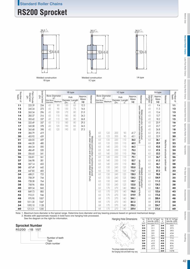
42
36.0 36.0 36.0
L
d DH
DP
DO
L
d DH
DP
DO d DP
DO
0-1.2
0-1.2
0-1.2
Welded construction1C type
Welded construction1B type
1A type
Machine-structural carbon steel
Welded construction: m
achine-structuralcarbon steel (teeth) and structural rolled steel (hub)
Welded construction: m
achine-structuralcarbon steel (teeth) and structural rolled steel (hub)
Welded construction:
structural rolled steel (teeth and hub)
Note: 1. Maximum bore diameter is the typical range. Determine bore diameter and key bearing pressure based on general mechanical design.2. Models with approximate masses in bold have one hanging hole processed.
See the diagram on the right for information.
Sprocket Number
Chain numberTypeNumber of teeth
Num
ber ofTeeth
1C type
Approx.Mass(kg)
Material
Pilot BoreD
iameter
(d)
1A type
Num
ber ofTeeth
Pitch C
ircularD
iameter
(DP)
Sprocket Outer Diameter(D
O)
Bore Diameter(d ) Hub
Pilot BoreDiameter Maximum Diameter
(DH )Length
(L )
Approx.Mass
(kg)M
aterial
1B type
Bore Diameter(d ) Hub
Pilot BoreDiameter Maximum Diameter
(DH )Length
(L )
Approx.Mass
(kg)
Material
Standard Roller Chains
RS200 Sprocket
11 225.39 254 43 80 130 65 12.3 16.6 21.0 24.3 26.8 29.5 34.5 37.5
43 9.4 11.3 13.4 15.7 18.2 20.9 23.7 26.8 29.5 32.9 36.1 39.9 43.8 47.8 52.2 56.7 61.3 66.1 76.3 87.2 98.8
104.9 111.2 124.2 138.1 152.6 175.8 200.4 217.8 254.7 315.6
1112 245.34 275 43 90 150 75 43 1213 265.34 296 43 100 170 80 43 1314 285.37 316 43 110 180 80 43 1415 305.42 337 43 115 180 80 43 1516 325.49 357 43 115 180 80 43 1617 345.58 378 43 120 190 85 43 1718 365.68 398 43 120 190 85 43 1819 385.79 419 63 125 200 90 41.7
45.1 56.5 60.2 66.2 70.3 74.6 79.1 83.7 88.5
105.8 116.7 128.3 134.5 140.7 153.8 182.3 196.8 219.9 244.1 261.5 298.5 359.4
63 1920 405.92 439 63 125 200 90 63 2021 426.05 459 63 135 220 110 63 2122 446.20 480
466.34 50063 135 220 11063 140 230 110
6363
2223 2324 486.49 520 63 140 230 110 63 2425 506.65 541 63 140 230 110 63 2526 526.81 561
546.98 581567.14 602
63 140 230 11063 140 230 11063 140 230 110
636363
2627 2728 2830 607.49 642
647.85 683688.21 723
63 150 240 12563 150 240 12563 150 240 125
63 150 240 12563 150 240 125
6363
3032 3234 3435 708.39 744
728.58 764768.96 804
63 150 240 125 6363
6363
3536 3638 3840 809.34 845
849.73 88563 170 270 14063 170 270 140
6363
4042 4245 910.31 946 63 170 270 140 63 4548 970.90 1007 68 170 270 140
68 170 270 14068 170 270 140
686868
4850 5054 5460 1213.31 1250
1092.10 11281011.30 1047
68 170 270 140 68 60
412432472513
392371351331311291
323028272625
23
2122
24
5535735936346747157758368769571078
505460
40424548
38363534
The phase relationship between the hanging hole and teeth may vary.
Hanging Hole Dimensions
Hole position (P.C.D.)
Hole d
ia.
(φ)
1B, 1C, 1A Typebore dia. (φ40)
1B, 1C, 1A Typebore dia. (φ40)
No.of
teeth
No.of
teethHole position (P.C.D.) Hole position (P.C.D.)
Befo
re Use
Standard R
oller Chains
Lube-Free Roller C
hainsH
eavy Duty R
oller Chains
Corrosion Resistant Roller ChainsS
pecialty Roller C
hainsS
pro
cketsP
in G
ear Drives
Accesso
riesS
election
Han
dlin
g

43
L1
CC
L2
L1L1
L
9.5
23.81
9.5
47.63
47.6
3
L1L2
62.4
72.4
76.20 76.20
L1
C
L 2
RS240-1 1 103.4 47.9 55.5 106.7
87.8
550.4{56125} 623 {63500} 686 {70000} 99.0{10100} 24.5
RS240-5 5 455.0 223.75 231.25 462.0 3110{317500} 3430{350000} 386{39390} 118.6
RS240-6 6 542.8 267.7 275.1 550.1 3740{381000} 4120{420000} 456{46460} 142.1
RS240-2 2 191.3 91.9 99.4 198.4 1100.8{112250} 1250{127000} 1370{140000} 168{17170} 48.1
RS240-3 3 279.0 135.85 143.15 286.3 1651.2{168376} 1870{190500} 2060{210000} 248{25250} 71.6
RS240-4 4 367.1 179.8 187.3 374.2 2490{254000} 2750{280000} 327{33330} 95.1
A B C
5 10 15 20 25 30 40 50 60 80 100 125 150 175 200 250 300 350 400 450
5.746.437.137.838.54
9.259.9710.711.412.1
12.913.614.315.115.8
16.617.318.1
10.712.013.314.615.9
17.318.619.921.322.7
24.025.426.828.129.5
30.932.333.7
15.417.319.221.123.0
24.926.828.730.732.6
34.636.638.540.542.5
44.546.548.5
20.022.424.827.329.7
32.234.737.239.742.3
44.847.449.952.555.1
57.760.362.9
24.427.430.433.436.4
39.442.445.548.651.7
54.857.961.064.267.3
70.573.776.9
28.832.335.839.342.8
46.450.053.657.260.9
64.668.271.975.679.3
83.186.890.6
37.341.846.350.955.5
60.164.869.574.278.9
83.688.493.298.0103
108112117
45.651.156.762.267.9
73.579.284.990.796.4
102108114120126
132137143
53.760.266.873.380.0
86.693.3100107114
120127134141148
155162169
69.678.086.595.0104
112121130138147
156165174183192
201210219
85.195.4106116127
137148158169180
191202213223234
246257268
104117129142155
168181194207220
233246260273287
300314327
123137152167182
198213228244259
275290306322338
354370386
141158175192210
227245262280298
316330345346370
396410418
159178197217236
256276296300303
317330345346370
396410418
159183202222242
263283299300303
317330345346370
396410418
159183202222242
263283299300303
317330345342359
376388397
126148170194219
245271269281291
304316328339350
360370380
103121140159179
200222245268281
293304314315334
86.5101116
910111213
1415161718
1920212223
242526
-
-
-
Triple strandSingle strand Double strand
RS240-1 Maximum Kilowatt Ratings Table (kW Ratings for Single Strand Chain)
Small Sprocket Max rpm
Small Sprocket
Lubrication Type
No. of Teeth
Number of chain strandsNumber of chain strands Multi-strand factorMulti-strand factor1.7 3.92.5 4.63.3 - -
A
B
C
Manual lubrication or drip lubricationDetails
onPg. 193
Oil bath or slinger disc lubrication
Forced pump lubrication
Lubricationmethod
Quintuple strandSextuple strand
Double strandTriple strand
Quadruple strand
Multi-strandfactor
L1+L2 L1 L2 L kN{kg f }C kN{kg f } kN{kg f } kN{kg f } kg/m
Drawing Scale 1/9.5
Riveting
Note: 1. Maximum allowable load when using a one-pitch offset link (OL) is 65% of the above. Two pitch offset links (2POL) can be used at 100% of the above values.2. Number of links per unit = 40
Dimensions DimensionsTSUBAKIChain Number
Numberof Strands
Pin LengthTransverse
PitchOffset Pin
Length Pin TypeMaximum
Allowable LoadApproximate
Mass
Note: 1. KW rating when using a one-pitch offset link (OL) is 65% of the above. Two pitch offset links (2POL) can be used at 100% of the above values.2. Please contact a Tsubaki representative prior to use of kW ratings in the colored area of the table.
ANSI StandardMin. Tensile Strength
Tsubaki MinimumTensile Strength
Tsubaki AverageTensile Strength
Standard Roller Chains RS Roller Chain
RS240Befo
re Use
Standard R
oller Chains
Lube-Free Roller C
hainsH
eavy Duty R
oller Chains
Corrosion Resistant Roller ChainsS
pecialty Roller C
hainsS
pro
cketsP
in G
ear Drives
Accesso
riesS
election
Han
dlin
g
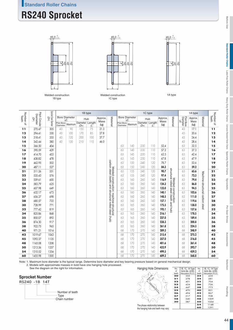
44
45.0 45.0 45.0
L
d DH
DP
DO
L
d DH
DP
DO d DP
DO
0-1.2
0-1.2
0-1.2
Welded construction1C type
Welded construction1B type
1A type
Machine-structural carbon steel
Welded construction: m
achine-structuralcarbon steel (teeth) and structural rolled steel (hub)
Welded construction:
structural rolled steel (teeth and hub)
Note: 1. Maximum bore diameter is the typical range. Determine bore diameter and key bearing pressure based on general mechanical design.2. Models with approximate masses in bold have one hanging hole processed.
See the diagram on the right for information.
Sprocket Number
Chain numberTypeNumber of teeth
Num
ber ofTeeth
1C type
Approx.Mass(kg)
Material
Pilot BoreD
iameter
(d)
1A type
Num
ber ofTeeth
Pitch C
ircularD
iameter
(DP)
Sprocket Outer Diameter(D
O)
Bore Diameter(d ) Hub
Pilot BoreDiameter Maximum Diameter
(DH )Length
(L )
Approx.Mass
(kg)M
aterial
1B type
Bore Diameter(d ) Hub
Pilot BoreDiameter Maximum Diameter
(DH )Length
(L )
Approx.Mass
(kg)
Material
Standard Roller Chains
RS240 Sprocket
11 270.47 305 43 90 150 75 21.3 27.8 37.7 46.0
43 17.1 20.6 24.4 28.6 32.5 37.3 42.4 47.9 53.6 59.2 65.6 72.3 79.4 86.8 94.5
102.6 111.0 119.6 138.0 157.6 178.5 189.4 200.8 224.3 248.9 275.2 316.8 361.4 392.7 459.2 568.8
1112 294.41 330 43 100 170 85 43 1213 318.41 355 43 120 200 100 43 1314 342.44 380 43 130 210 110 43 1415 366.50 404 63 140 230 110 52.4
57.2 62.3 67.8 78.7 84.3 90.7 97.4
116.9 124.3 132.0 140.1 148.5 157.1 175.5 195.1 216.1 227.0 238.3 261.8 289.3 315.4 357.0 401.6 432.9 499.5 609.3
63 1516 390.59 429 63 140 230 110 63 1617 414.70 453 63 145 230 110 63 1718 438.82 478 63 145 230 110 63 1819 462.95 502 63 150 240 120 63 1920 487.11 527 63 150 240 120 63 2021 511.26 551 63 155 240 120 63 2122 535.43 576
559.61 60063 155 240 12063 160 260 140
6363
2223 2324 583.79 625 63 160 260 140 63 2425 607.98 649 63 160 260 140 63 2526 632.17 673
656.37 698680.57 722
63 160 260 14063 160 260 14063 160 260 140
636363
2627 2728 2830 728.99 771
777.42 819825.86 868
63 165 260 14063 165 260 14063 165 260 140
636363
3032 3234 3435 850.07 892
874.30 917922.75 965
63 165 260 14063 165 260 14063 165 260 140
636363
3536 3638 3840 971.21 1014 68 170 270 140
68 170 270 1406868
4042 4245 1092.37 1135
1019.67 1063
1213.56 12571310.52 1354
68 170 270 140 68 4548 1165.08 1208 68 170 270 140
68 170 270 14068 170 270 140
686868
4850 5054 5460 1455.98 1500 68 170 270 140 68 60
517540587
494470447424401378355
30
28272625
23
2120
22
24
6356817047267738218679381009105411481291
505460
40424548
3836353432
The phase relationship between the hanging hole and teeth may vary.
Hanging Hole Dimensions
Hole position (P.C.D.)
Hole d
ia.
(φ)
1B, 1C, 1A Typebore dia. (φ40)
1B, 1C, 1A Typebore dia. (φ40)
No.of
teeth
No.of
teethHole position (P.C.D.) Hole position (P.C.D.)
Befo
re Use
Standard R
oller Chains
Lube-Free Roller C
hainsH
eavy Duty R
oller Chains
Corrosion Resistant Roller ChainsS
pecialty Roller C
hainsS
pro
cketsP
in G
ear Drives
Accesso
riesS
election
Han
dlin
g
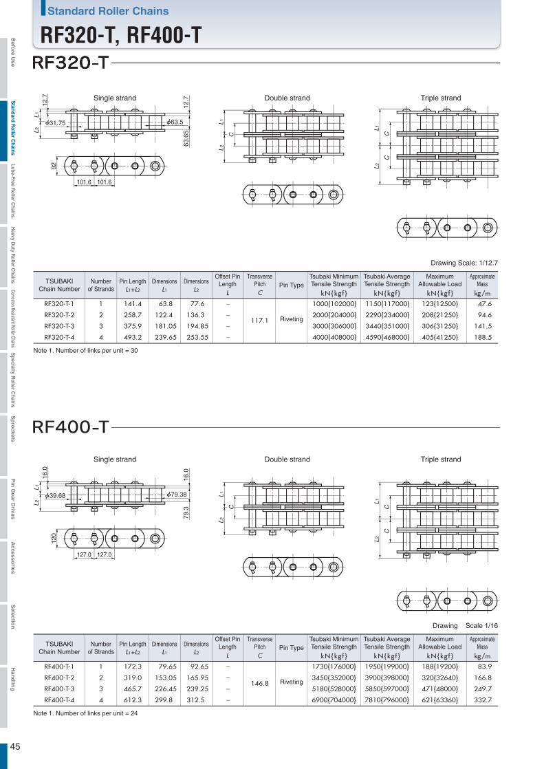
45
L1
CC
L2
12.7
31.75
12.7
63.5
63.6
5
L 1L2
92
101.6 101.6
L1
C
L2
L1
CC
L2
16.0
39.68
16.0
79.38
79.3
L 1L2
120
127.0 127.0
L1
C
L2
RF320-T-1 1 141.4 63.8 77.6 -
117.1
1000{102000} 1150{117000} 123{12500} 47.6
RF320-T-2 2 258.7 122.4 136.3 - 2000{204000} 2290{234000} 208{21250} 94.6
RF320-T-3 3 375.9 181.05 194.85 - 3000{306000} 3440{351000} 306{31250} 141.5
RF320-T-4 4 493.2 239.65 253.55 - 4000{408000} 4590{468000} 405{41250} 188.5
RF400-T-1 1 172.3 79.65 92.65 -
146.8
1730{176000} 1950{199000} 188{19200} 83.9
RF400-T-2 2 319.0 153.05 165.95 - 3450{352000} 3900{398000} 320{32640} 166.8
RF400-T-3 3 465.7 226.45 239.25 - 5180{528000} 5850{597000} 471{48000} 249.7
RF400-T-4 4 612.3 299.8 312.5 - 6900{704000} 7810{796000} 621{63360} 332.7
Note 1. Number of links per unit = 30
Note 1. Number of links per unit = 24
Triple strandSingle strand Double strand
Triple strandSingle strand Double strand
Drawing Scale: 1/12.7
Drawing Scale 1/16
L1
DimensionsL2
DimensionsTSUBAKIChain Number
Numberof Strands L1+L2
Pin Length
C
TransversePitch
L
Offset PinLength Pin Type
kN{kg f } kN{kg f } kN{kg f }
MaximumAllowable Load
kg/m
ApproximateMass
Riveting
L1
DimensionsL2
DimensionsTSUBAKIChain Number
Numberof Strands L1+L2
Pin Length
C
TransversePitch
L
Offset PinLength Pin Type
kN{kg f } kN{kg f } kN{kg f }
MaximumAllowable Load
kg/m
ApproximateMass
Riveting
Tsubaki MinimumTensile Strength
Tsubaki AverageTensile Strength
Tsubaki MinimumTensile Strength
Tsubaki AverageTensile Strength
Standard Roller Chains
RF320-T, RF400-TBefo
re Use
Standard R
oller Chains
Lube-Free Roller C
hainsH
eavy Duty R
oller Chains
Corrosion Resistant Roller ChainsS
pecialty Roller C
hainsS
pro
cketsP
in G
ear Drives
Accesso
riesS
election
Han
dlin
g
M E M O
46
Befo
re Use
Standard R
oller Chains
Lube-Free Roller C
hainsH
eavy Duty R
oller Chains
Corrosion Resistant Roller ChainsS
pecialty Roller C
hainsS
pro
cketsP
in G
ear Drives
Accesso
riesS
election
Han
dlin
g
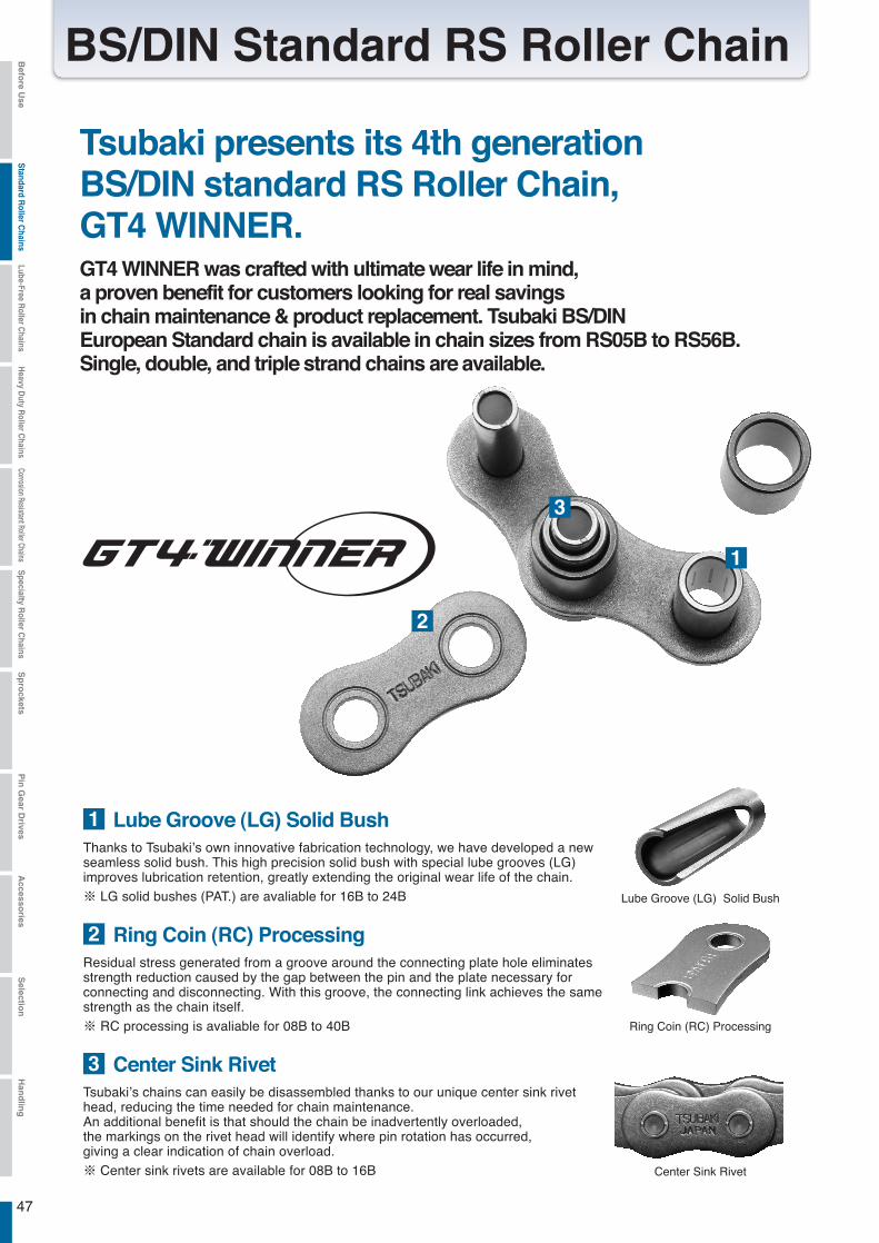
47
BS/DIN Standard RS Roller ChainBefo
re Use
Standard R
oller Chains
Lube-Free Roller C
hainsH
eavy Duty R
oller Chains
Corrosion Resistant Roller ChainsS
pecialty Roller C
hainsS
pro
cketsP
in G
ear Drives
Accesso
riesS
election
Han
dlin
g
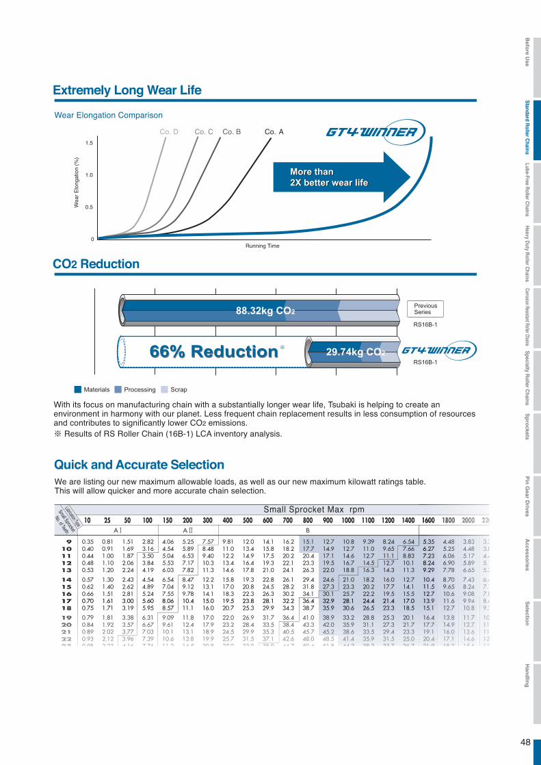
48
Befo
re Use
Standard R
oller Chains
Lube-Free Roller C
hainsH
eavy Duty R
oller Chains
Corrosion Resistant Roller ChainsS
pecialty Roller C
hainsS
pro
cketsP
in G
ear Drives
Accesso
riesS
election
Han
dlin
g
rpm
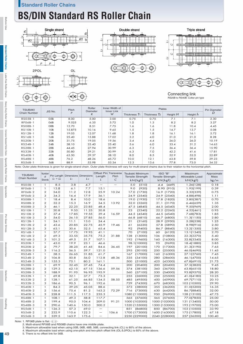
49
Connecting linkRS20B to RS40B: Cotter pin type
L2L
T2
W
H
T1
h
1
L
C
CC
2L1
L2L1
L1L
L
1
D
P P
R
Triple strandSingle strand Double strand
Note: 1. RF06B plate is flat:2. Multi-strand RF06B and RS08B chains have one middle plate.3. Maximum allowable load when using 05B, 06B, 48B, 56B, connecting link (CL) is 80% of the above.4. Maximum allowable load when using one-pitch and two-pitch offset link (OL&2POL) is 60% of the above.5. There is no offset link for 56B.
RF06B-1 06B 9.525 6.35 5.72 1.0 8.2 8.2 3.27RS05B-1 05B 8.00 5.00 3.00 0.75 7.1 7.1 2.30
RS08B-1 08B 12.70 8.51 7.75 1.6 11.8 10.4 4.45RS10B-1 10B 15.875 10.16 9.65 1.5 14.7 13.7 5.08RS12B-1 12B 19.05 12.07 11.68 1.8 16.1 16.1 5.72RS16B-1 16B 25.40 15.88 17.02 3.2 21.0 21.0 8.28RS20B-1 20B 31.75 19.05 19.56 3.4 26.0 26.0 10.19RS24B-1 24B 38.10 25.40 25.40 5.6 33.4 31.2 14.63RS28B-1 28B 44.45 27.94 30.99 6.3 36.4 36.4 15.90RS32B-1 32B 50.80 29.21 30.99 6.3 42.2 41.6 17.81RS40B-1 40B 63.50 39.37 38.10 8.0 52.9 52.0 22.89
kN{kg f }
RF06B-1 1 13.8 6.1 7.7 15.125.936.1
10.249.0 {920} 8.90
4.40.39
RS05B-1 1 8.5 3.8 4.7 - - 5.0 {510} 0.18
RF06B-2 2 24.0 11.2 12.8 17.0 {1730} 16.9 0.75RF06B-3 3 34.3 16.4 17.9 24.9 {2540} 24.9 1.11RS08B-1 1 18.4 8.4 10.0 18.6 19.0 {1930} 17.8 0.70RS08B-2 2 32.2 15.3 16.9 34.5 32.0 {3260} 31.1 1.35RS08B-3 3 46.1 22.25 23.85 48.4 47.5 {4840} 44.5 2.00RS10B-1 1 20.8 9.55 11.25 20.8 23 {2340} 22.2 0.95RS10B-2 2 37.4 17.85 19.55 39.4 44.5 {4540} 44.5 1.85RS10B-3 3 54.0 26.15 27.85 56.0 66.8 {6810} 66.7 2.80RS12B-1 1 24.1 11.1 13.0 24.4 31 {3160} 28.9 1.25RS12B-2 2 43.6 20.85 22.75 45.9 61 {6220} 57.8 2.50RS12B-3 3 63.1 30.6 32.5 65.4 92 {9400} 86.7
{910}{449}
{1720}{2540}{1820}{3170}{4540}{2260}{4540}{6800}{2950}{5890}{8840} 3.80
RS16B-1 1 37.7 17.75 19.95 41.1 70 {7100} 60 {6120} 2.70RS16B-2 2 69.3 33.55 35.75 75.2 128 {13000} 106 {10800} 5.40RS16B-3 3 101.2 49.5 51.7 107.1 192 {19600} 160 {16300} 8.00RS20B-1 1 43.0 19.9 23.1 46.6 98.1{10000} 95 {9690} 3.85RS20B-2 2 79.7 38.25 41.45 84.6 197 {20100} 170 {17300} 7.65RS20B-3 3 116.2 56.5 59.7 121.0 295 {30100} 250 {25500} 11.45RS24B-1 1 58.5 26.65 31.85 61.7 167 {17000} 160 {16300} 7.45RS24B-2 2 106.8 50.8 56.0 112.8 335 {34100} 280 {28600} 14.65RS24B-3 3 155.3 75.1 80.2 161.1 500 {51000} 425 {43300} 21.75RS28B-1 1 69.9 32.45 37.45 74.4 200 {20400} 200 {20400} 9.45RS28B-2 2 129.3 62.15 67.15 136.6 374 {38100} 360 {36700} 18.80RS28B-3 3 188.9 91.95 96.95 195.9 560 {57100} 530 {54000} 28.20RS32B-1 1 69.8 32.1 37.7 73.3 255 {26000} 250 {25500} 10.25RS32B-2 2 128.1 61.25 66.85 134.5 485 {49500} 450 {45900} 20.10RS32B-3 3 186.6 90.5 96.1 192.6 729 {74300} 670 {68300} 29.90RS40B-1 1 84.3 39.25 45.05 88.6 373 {38000} 355 {36200} 16.35RS40B-2 2 156.6 75.4 81.2 163.2 716 {73000} 630 {64200} 32.00RS40B-3RS48B-1RS48B-2RS48B-3RS56B-1RS56B-2RS56B-3
3 228.8 111.5 117.3 235.3 1080 {110000} 950 {96900} 47.751 108.1 49.3 58.8 117.7 565 {57600} 565 {57600} 25.002 199.4 95.0 104.4 209.0 1000 {102000} 1000 {102000} 50.003 290.6 140.6 150.0 300.2 1520 {155000} 1500 {153000} 75.001 126.3 57.3 69.0 - 851 {86800} 850 {86700} 33.902 232.9 110.6 122.3 - 1700 {173000} 1600 {163000} 67.183 339.5 163.9 175.6 - 2250 {229000} 2240 {228000} 100.40
13.92
16.59
19.46
31.88
36.45
48.36
59.56
58.55
72.29
91.21
106.6
PitchP
RollerDiameter
R
Inner Width ofInner Link
W
PlatesJIS No.
Thickness T1 Thickness T2 Height H Height h
Pin DiameterD
Note: Outer plate thickness is given for single-strand chain. Outer plate thickness will vary for multi-strand chains due to their relation to the horizontal pitch.
Numberof
Strands
Pin LengthL1+L2
DimensionsL1
DimensionsL 2
Offset PinLength
L
ISO "B"Tensile Strength
TSUBAKIChain Number
TSUBAKIChain Number
C
TransversePitch
kN{kg f } kg/m
ApproximateMass
Tsubaki MinimumTensile Strength
1.30.75
1.61.51.84.04.46.07.57.08.5
RS48B-1 48B 76.2 48.26 45.72 10.0 63.8 59.8 29.2312.1RS56B-1 56B 88.9 53.98 53.34 12.3 77.8 73.0 34.3213.6
kN{kg f }
MaximumAllowable Load
1.26{128}1.95{199}3.32{339}4.88{498}3.80{387}6.46{659}9.50{969}4.52{461}7.68{783}
11.3{1150}5.28{538}8.98{916}
13.2{1350}13.1{1340}22.3{2270}32.8{3340}18.4{1880}31.3{3190}46.0{4690}27.1{2760}46.1{4700}67.8{6910}37.5{3820}63.8{6510}93.8{9570}41.0{4180}69.7{7110}
103 {10500}51.0{5200}86.7{8840}
128 {13100}77.0{7850}
131 {13400}193 {19700}103 {10500}175 {17800}257 {26200}
Standard Roller Chains
BS/DIN Standard RS Roller ChainBefo
re Use
Standard R
oller Chains
Lube-Free Roller C
hainsH
eavy Duty R
oller Chains
Corrosion Resistant Roller ChainsS
pecialty Roller C
hainsS
pro
cketsP
in G
ear Drives
Accesso
riesS
election
Han
dlin
g
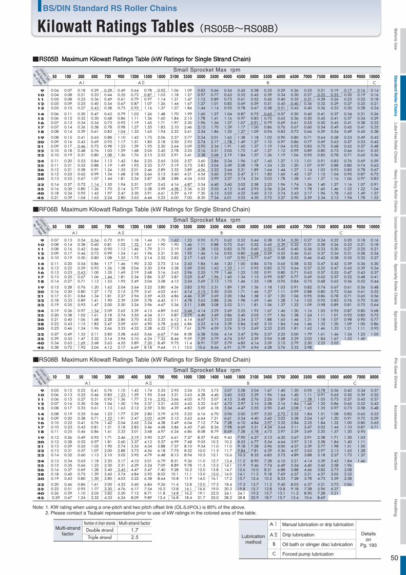
50
B CA A
50 100 300 500 700 900 1200 1500 1800 2100 2500 3000 3500 4000 4500 5000 5500 6000 6500 7000 7500 8000 8500 9000 10000
10 25 50 100 200 300 400 500 700 900 1000 1200 1400 1600 1800 2100 2400 2700 3000 3500 4000 5000 6000 7000 8000
0.04 0.04 0.05 0.05 0.05
0.06 0.06 0.07 0.07 0.08
0.08 0.09 0.09 0.10 0.10
0.11 0.11 0.12 0.12 0.13
0.14 0.16 0.18 0.21
0.07 0.08 0.08 0.09 0.10
0.11 0.12 0.13 0.14 0.14
0.15 0.16 0.17 0.18 0.19
0.20 0.21 0.21 0.23 0.25
0.27 0.30 0.34 0.39
0.18 0.21 0.23 0.25 0.27
0.30 0.32 0.34 0.36 0.39
0.41 0.43 0.46 0.48 0.51
0.53 0.55 0.58 0.62 0.67
0.72 0.80 0.92 1.04
0.29 0.33 0.36 0.40 0.43
0.47 0.50 0.54 0.58 0.61
0.65 0.69 0.73 0.76 0.80
0.84 0.88 0.91 0.99 1.07
1.14 1.26 1.45 1.65
0.39 0.44 0.49 0.54 0.58
0.63 0.68 0.73 0.78 0.83
0.88 0.93 0.98 1.03 1.08
1.13 1.19 1.24 1.34 1.44
1.55 1.70 1.97 2.24
0.49 0.55 0.61 0.67 0.73
0.79 0.86 0.92 0.98 1.04
1.10 1.17 1.23 1.29 1.36
1.42 1.49 1.55 1.68 1.81
1.94 2.14 2.47 2.80
0.64 0.72 0.79 0.87 0.95
1.03 1.11 1.19 1.27 1.35
1.43 1.51 1.59 1.68 1.76
1.84 1.93 2.01 2.18 2.34
2.51 2.77 3.20 3.63
0.78 0.87 0.97 1.07 1.16
1.26 1.36 1.45 1.55 1.65
1.75 1.85 1.95 2.05 2.15
2.25 2.35 2.46 2.66 2.87
3.07 3.38 3.91 4.44
0.92 1.03 1.14 1.26 1.37
1.48 1.60 1.71 1.83 1.94
2.06 2.18 2.30 2.42 2.53
2.65 2.77 2.89 3.13 3.38
3.62 3.99 4.61 5.23
1.06 1.18 1.31 1.44 1.57
1.70 1.84 1.97 2.10 2.23
2.37 2.50 2.64 2.78 2.91
3.05 3.19 3.32 3.60 3.88
4.16 4.58 5.29 6.00
1.09 1.27 1.47 1.67 1.84
1.99 2.15 2.30 2.46 2.61
2.77 2.93 3.09 3.25 3.41
3.57 3.73 3.89 4.21 4.54
4.87 5.36 6.19 7.00
0.83 0.97 1.12 1.27 1.44
1.60 1.78 1.96 2.15 2.34
2.54 2.74 2.95 3.16 3.38
3.60 3.83 4.06 4.54 5.03
5.54 6.32 7.30 8.30
0.66 0.77 0.89 1.01 1.14
1.27 1.41 1.56 1.70 1.86
2.01 2.17 2.34 2.51 2.68
2.86 3.04 3.22 3.60 3.99
4.40 5.03 6.15 7.34
0.54 0.63 0.73 0.83 0.93
1.04 1.16 1.27 1.39 1.52
1.65 1.78 1.91 2.05 2.19
2.34 2.49 2.64 2.95 3.27
3.60 4.12 5.03 6.01
0.45 0.53 0.61 0.69 0.78
0.87 0.97 1.07 1.17 1.27
1.38 1.49 1.60 1.72 1.84
1.96 2.08 2.21 2.47 2.74
3.02 3.45 4.22 5.03
0.38 0.45 0.52 0.59 0.67
0.75 0.83 0.91 1.00 1.09
1.18 1.27 1.37 1.47 1.57
1.67 1.78 1.89 2.11 2.34
2.58 2.95 3.60 4.30
0.33 0.39 0.45 0.51 0.58
0.65 0.72 0.79 0.86 0.94
1.02 1.10 1.19 1.27 1.36
1.45 1.54 1.64 1.83 2.03
2.23 2.56 3.12 3.72
0.29 0.34 0.40 0.45 0.51
0.57 0.63 0.69 0.76 0.83
0.90 0.97 1.04 1.12 1.19
1.27 1.35 1.44 1.60 1.78
1.96 2.24 2.74 3.27
0.26 0.30 0.35 0.40 0.45
0.50 0.56 0.61 0.67 0.73
0.80 0.86 0.92 0.99 1.06
1.13 1.20 1.27 1.42 1.58
1.74 1.99 2.43 2.90
0.23 0.27 0.31 0.36 0.40
0.45 0.50 0.55 0.60 0.66
0.71 0.77 0.83 0.89 0.95
1.01 1.07 1.14 1.27 1.41
1.56 1.78 2.17 2.59
0.21 0.25 0.28 0.32 0.36
0.41 0.45 0.50 0.54 0.59
0.64 0.69 0.75 0.80 0.85
0.91 0.97 1.03 1.15 1.27
1.40 1.60 1.96 2.34
0.19 0.22 0.26 0.29 0.33
0.37 0.41 0.45 0.49 0.54
0.58 0.63 0.68 0.73 0.78
0.83 0.88 0.93 1.04 1.16
1.27 1.46 1.78 2.12
0.17 0.20 0.23 0.27 0.30
0.34 0.37 0.41 0.45 0.49
0.53 0.57 0.62 0.66 0.71
0.76 0.80 0.85 0.95 1.06
1.16 1.33 1.62 1.94
0.16 0.19 0.22 0.25 0.28
0.31 0.34 0.38 0.41 0.45
0.49 0.53 0.57 0.61 0.65
0.69 0.74 0.78 0.87 0.97
1.07 1.22 1.49 1.78
0.14 0.16 0.18 0.21 0.24
0.26 0.29 0.32 0.35 0.38
0.42 0.45 0.48 0.52 0.56
0.59 0.63 0.67 0.75 0.83
0.91 1.04 1.27 1.52
■RS05B Maximum Kilowatt Ratings Table (kW Ratings for Single Strand Chain)
Small Sprocket Max rpm
A B CA
■RS08B Maximum Kilowatt Ratings Table (kW Ratings for Single Strand Chain)
Small Sprocket
No. of TeethLubrication Type
910111213
1415161718
1920212223
2425262830
32354045
50 100 300 500 700 900 1200 1500 1800 2100 2500 3000 3500 4000 4500 5000 5500 6000 6500 7000 7500 8000 8500 9000 10000
■RF06B Maximum Kilowatt Ratings Table (kW Ratings for Single Strand Chain)
Small Sprocket Max rpm
A B CA
Small Sprocket
No. of TeethLubrication Type
Small Sprocket Max rpmSmall Sprocket
No. of TeethLubrication Type
Note: 1. KW rating when using a one-pitch and two pitch offset link (OL&2POL) is 80% of the above. 2. Please contact a Tsubaki representative prior to use of kW ratings in the colored area of the table.
Drip lubrication
Number of chain strands Multi-strand factor1.72.5
B
C
Detailson
Pg. 193Oil bath or slinger disc lubrication
Forced pump lubrication
Lubricationmethod
Double strandTriple strand
Multi-strandfactor
A Manual lubrication or drip lubrication
910111213
1415161718
1920212223
2425262830
32354045
0.07 0.08 0.08 0.09 0.10
0.11 0.12 0.13 0.13 0.14
0.15 0.16 0.17 0.18 0.19
0.19 0.20 0.21 0.23 0.25
0.27 0.29 0.34 0.38
0.13 0.14 0.16 0.17 0.19
0.20 0.22 0.23 0.25 0.27
0.28 0.30 0.31 0.33 0.35
0.36 0.38 0.40 0.43 0.46
0.49 0.55 0.63 0.72
0.34 0.38 0.42 0.46 0.50
0.54 0.59 0.63 0.67 0.71
0.76 0.80 0.84 0.89 0.93
0.97 1.02 1.06 1.15 1.24
1.33 1.47 1.69 1.92
0.54 0.60 0.66 0.73 0.80
0.86 0.93 1.00 1.06 1.13
1.20 1.27 1.34 1.41 1.47
1.54 1.61 1.68 1.82 1.96
2.11 2.32 2.68 3.04
0.72 0.81 0.90 0.99 1.08
1.17 1.26 1.35 1.44 1.53
1.62 1.72 1.81 1.90 2.00
2.09 2.18 2.28 2.47 2.66
2.85 3.14 3.63 4.12
0.91 1.02 1.13 1.24 1.35
1.46 1.58 1.69 1.81 1.92
2.04 2.15 2.27 2.39 2.50
2.62 2.74 2.86 3.09 3.33
3.58 3.94 4.55 5.17
1.18 1.32 1.46 1.61 1.75
1.90 2.04 2.19 2.34 2.49
2.64 2.79 2.94 3.09 3.24
3.39 3.55 3.70 4.01 4.32
4.63 5.10 5.89 6.69
1.44 1.61 1.79 1.96 2.14
2.32 2.50 2.68 2.86 3.04
3.22 3.41 3.59 3.78 3.96
4.15 4.34 4.52 4.90 5.28
5.66 6.24 7.20 8.18
1.70 1.90 2.11 2.31 2.52
2.73 2.94 3.16 3.37 3.58
3.80 4.02 4.23 4.45 4.67
4.89 5.11 5.33 5.78 6.22
6.67 7.35 8.49 9.64
1.62 1.90 2.19 2.50 2.82
3.14 3.38 3.63 3.87 4.12
4.36 4.61 4.86 5.11 5.36
5.62 5.87 6.12 6.63 7.15
7.66 8.44 9.75 11.1
1.25 1.46 1.69 1.92 2.17
2.43 2.69 2.96 3.25 3.54
3.83 4.14 4.46 4.78 5.11
5.44 5.79 6.14 6.86 7.61
8.38 9.59 11.4 13.0
0.95 1.11 1.28 1.46 1.65
1.84 2.05 2.25 2.47 2.69
2.92 3.15 3.39 3.63 3.88
4.14 4.40 4.67 5.22 5.79
6.38 7.29 8.91 10.6
0.75 0.88 1.02 1.16 1.31
1.46 1.62 1.79 1.96 2.13
2.31 2.50 2.69 2.88 3.08
3.29 3.49 3.71 4.14 4.59
5.06 5.79 7.07 8.44
0.62 0.72 0.83 0.95 1.07
1.20 1.33 1.46 1.60 1.75
1.89 2.05 2.20 2.36 2.52
2.69 2.86 3.03 3.39 3.76
4.14 4.74 5.79 6.91
0.52 0.61 0.70 0.80 0.90
1.00 1.11 1.23 1.34 1.46
1.59 1.71 1.84 1.98 2.11
2.25 2.40 2.54 2.84 3.15
3.47 3.97 4.85 5.79
0.44 0.52 0.60 0.68 0.77
0.86 0.95 1.05 1.15 1.25
1.36 1.46 1.58 1.69 1.81
1.92 2.05 2.17 2.43 2.69
2.96 3.39 4.14 4.94
0.38 0.45 0.52 0.59 0.67
0.74 0.82 0.91 0.99 1.08
1.18 1.27 1.37 1.46 1.56
1.67 1.77 1.88 2.10 2.33
2.57 2.94 3.59 4.28
0.34 0.39 0.45 0.52 0.58
0.65 0.72 0.80 0.87 0.95
1.03 1.11 1.20 1.28 1.37
1.46 1.56 1.65 1.84 2.05
2.25 2.58 3.15 3.76
0.30 0.35 0.40 0.46 0.52
0.58 0.64 0.71 0.77 0.84
0.91 0.99 1.06 1.14 1.22
1.30 1.38 1.46 1.64 1.81
2.00 2.29 2.79 3.33
0.27 0.31 0.36 0.41 0.46
0.52 0.57 0.63 0.69 0.75
0.82 0.88 0.95 1.02 1.09
1.16 1.24 1.31 1.46 1.62
1.79 2.05 2.50 2.98
0.24 0.28 0.33 0.37 0.42
0.47 0.52 0.57 0.62 0.68
0.74 0.80 0.86 0.92 0.98
1.05 1.11 1.18 1.32 1.46
1.61 1.84 2.25
0.22 0.26 0.30 0.34 0.38
0.42 0.47 0.52 0.57 0.62
0.67 0.72 0.78 0.83 0.89
0.95 1.01 1.07 1.20 1.33
1.46 1.67 2.05
0.20 0.23 0.27 0.31 0.35
0.39 0.43 0.47 0.52 0.56
0.61 0.66 0.71 0.76 0.81
0.87 0.92 0.98 1.09 1.21
1.34 1.53
0.18 0.21 0.25 0.28 0.32
0.36 0.39 0.43 0.48 0.52
0.56 0.61 0.65 0.70 0.75
0.80 0.85 0.90 1.00 1.11
1.23 1.40
0.16 0.18 0.21 0.24 0.27
0.30 0.34 0.37 0.41 0.44
0.48 0.52 0.56 0.60 0.64
0.68 0.72 0.77 0.86 0.95
1.05
910111213
1415161718
1920212223
2425262830
32354045
0.05 0.06 0.06 0.07 0.08
0.08 0.09 0.10 0.10 0.11
0.12 0.12 0.13 0.13 0.14
0.15 0.15 0.16 0.18 0.19
0.20 0.22 0.26 0.29
0.12 0.13 0.15 0.16 0.17
0.19 0.20 0.22 0.23 0.25
0.26 0.28 0.29 0.31 0.32
0.34 0.35 0.37 0.40 0.43
0.46 0.51 0.59 0.67
0.22 0.25 0.27 0.30 0.33
0.35 0.38 0.41 0.43 0.46
0.49 0.52 0.55 0.57 0.60
0.63 0.66 0.69 0.75 0.80
0.86 0.95 1.10 1.24
0.41 0.46 0.51 0.56 0.61
0.66 0.71 0.76 0.81 0.86
0.92 0.97 1.02 1.07 1.13
1.18 1.23 1.28 1.39 1.50
1.61 1.77 2.05 2.32
0.76 0.85 0.95 1.04 1.13
1.23 1.32 1.42 1.51 1.61
1.71 1.81 1.90 2.00 2.10
2.20 2.30 2.40 2.60 2.80
3.00 3.30 3.82 4.33
1.10 1.23 1.36 1.50 1.63
1.77 1.91 2.04 2.18 2.32
2.46 2.60 2.74 2.88 3.02
3.17 3.31 3.45 3.74 4.03
4.32 4.76 5.50 6.24
1.42 1.59 1.77 1.94 2.12
2.29 2.47 2.65 2.83 3.01
3.19 3.37 3.55 3.73 3.92
4.10 4.29 4.47 4.84 5.22
5.60 6.17 7.12 8.09
1.74 1.95 2.16 2.37 2.59
2.80 3.02 3.24 3.46 3.68
3.90 4.12 4.34 4.56 4.79
5.01 5.24 5.47 5.92 6.38
6.84 7.54 8.71 9.89
2.35 2.64 2.92 3.21 3.50
3.79 4.09 4.38 4.68 4.97
5.27 5.57 5.88 6.18 6.48
6.79 7.09 7.40 8.02 8.64
9.26 10.2 11.8 13.4
2.95 3.31 3.66 4.03 4.39
4.75 5.12 5.49 5.86 6.24
6.61 6.99 7.37 7.75 8.13
8.51 8.89 9.28 10.1 10.8
11.6 12.8 14.8 16.8
3.24 3.63 4.03 4.43 4.83
5.23 5.63 6.04 6.45 6.86
7.27 7.68 8.10 8.52 8.94
9.36 9.78 10.2 11.1 11.9
12.8 14.1 16.2 18.4
3.75 4.28 4.75 5.22 5.69
6.16 6.64 7.12 7.60 8.08
8.57 9.05 9.54 10.0 10.5
11.0 11.5 12.0 13.0 14.0
15.0 16.6 19.1 21.7
3.75 4.40 5.07 5.67 6.18
6.70 7.21 7.74 8.26 8.79
9.43 10.2 11.0 11.5 12.1
12.7 13.2 13.8 15.0 16.1
17.3 19.0 22.0 25.0
3.07 3.60 4.15 4.73 5.34
5.96 6.61 7.28 7.98 8.69
9.43 10.2 11.0 11.7 12.6
13.4 14.1 14.7 16.0 17.2
18.4 20.3 24.1 28.2
2.58 3.02 3.48 3.97 4.47
5.00 5.54 6.10 6.69 7.28
7.90 8.53 9.18 9.84 10.5
11.2 11.9 12.6 14.1 15.7
17.3 19.8 24.1 28.8
2.04 2.39 2.76 3.15 3.55
3.97 4.40 4.84 5.31 5.78
6.27 6.77 7.28 7.81 8.35
8.90 9.46 10.0 11.2 12.4
13.7 15.7 19.2 22.9
1.67 1.96 2.26 2.58 2.90
3.25 3.60 3.97 4.34 4.73
5.13 5.54 5.96 6.39 6.83
7.28 7.74 8.21 9.18 10.2
11.2 12.8 15.7 18.7
1.40 1.64 1.89 2.16 2.43
2.72 3.02 3.32 3.64 3.97
4.30 4.64 5.00 5.36 5.73
6.10 6.49 6.88 7.69 8.53
9.40 10.8 13.1 15.7
1.20 1.40 1.62 1.84 2.08
2.32 2.58 2.84 3.11 3.39
3.67 3.97 4.27 4.57 4.89
5.21 5.54 5.88 6.57 7.28
8.03 9.18 11.2 13.4
0.95 1.11 1.28 1.46 1.65
1.84 2.04 2.25 2.47 2.69
2.91 3.15 3.39 3.63 3.88
4.14 4.40 4.66 5.21 5.78
6.37 7.28 8.90 10.6
0.78 0.91 1.05 1.20 1.35
1.51 1.67 1.84 2.02 2.20
2.38 2.58 2.77 2.97 3.18
3.39 3.60 3.82 4.27 4.73
5.21 5.96 7.28 8.69
0.56 0.65 0.75 0.86 0.97
1.08 1.20 1.32 1.44 1.57
1.71 1.84 1.98 2.13 2.27
2.42 2.58 2.73 3.05 3.39
3.73 4.27 5.21
0.42 0.50 0.57 0.65 0.73
0.82 0.91 1.00 1.10 1.20
1.30 1.40 1.51 1.62 1.73
1.84 1.96 2.08 2.32 2.58
0.86
0.34 0.39 0.45 0.52 0.58
0.65 0.72 0.80 0.87 0.95
1.03 1.11 1.20 1.28 1.37
1.46
0.27 0.32 0.37 0.42 0.48
0.53 0.59 0.65 0.71
BS/DIN Standard RS Roller Chains
Kilowatt Ratings Tables(RS05B~RS08B) Befo
re Use
Standard R
oller Chains
Lube-Free Roller C
hainsH
eavy Duty R
oller Chains
Corrosion Resistant Roller ChainsS
pecialty Roller C
hainsS
pro
cketsP
in G
ear Drives
Accesso
riesS
election
Han
dlin
g

51
B CA A
910111213
1415161718
1920212223
2425262830
32354045
10 25 50 100 150 200 300 400 500 600 700 800 900 1000 1100 1200 1400 1600 1800 2000 2500 3000 3500 4000 4500
10 25 50 100 150 200 300 400 500 600 700 800 900 1000 1100 1200 1400 1600 1800 2000 2200 2400 2700 3000 3400
A B CA
910111213
1415161718
1920212223
2425262830
32354045
Note: 1. KW rating when using a one-pitch and two pitch offset link (OL&2POL) is 80% of the above. 2. Please contact a Tsubaki representative prior to use of kW ratings in the colored area of the table.
Drip lubrication
Number of chain strands Multi-strand factor1.72.5
B
C
Detailson
Pg. 193Oil bath or slinger disc lubrication
Forced pump lubrication
Lubricationmethod
Double strandTriple strand
Multi-strandfactor
A Manual lubrication or drip lubrication
■RS16B Maximum Kilowatt Ratings Table (kW Ratings for Single Strand Chain)
Small Sprocket Max rpmSmall Sprocket
No. of TeethLubrication Type
■RS12B Maximum Kilowatt Ratings Table (kW Ratings for Single Strand Chain)
Small Sprocket Max rpmSmall Sprocket
No. of TeethLubrication Type
A B CA10 25 50 100 200 300 400 500 700 900 1000 1200 1400 1600 1800 2100 2400 2700 3000 3500 4000 4500 5000 5500 6000
910111213
1415161718
1920212223
2425262830
32354045
■RS10B Maximum Kilowatt Ratings Table (kW Ratings for Single Strand Chain)
Small Sprocket Max rpmSmall Sprocket
No. of TeethLubrication Type
0.11 0.12 0.13 0.15 0.16
0.17 0.19 0.20 0.21 0.23
0.24 0.25 0.27 0.28 0.30
0.31 0.32 0.34 0.37 0.39
0.42 0.46 0.54 0.61
0.24 0.27 0.30 0.33 0.36
0.39 0.42 0.46 0.49 0.52
0.55 0.58 0.61 0.64 0.67
0.71 0.74 0.77 0.83 0.90
0.96 1.06 1.22 1.39
0.46 0.51 0.57 0.62 0.68
0.74 0.79 0.85 0.91 0.96
1.02 1.08 1.14 1.20 1.26
1.32 1.37 1.43 1.55 1.67
1.80 1.98 2.28 2.59
0.85 0.95 1.06 1.16 1.27
1.37 1.48 1.58 1.69 1.80
1.91 2.02 2.13 2.23 2.34
2.46 2.57 2.68 2.90 3.12
3.35 3.69 4.26 4.84
1.23 1.37 1.52 1.67 1.82
1.98 2.13 2.28 2.44 2.59
2.75 2.90 3.06 3.22 3.38
3.54 3.70 3.86 4.18 4.50
4.82 5.32 6.14 6.97
1.59 1.78 1.97 2.17 2.36
2.56 2.76 2.96 3.16 3.36
3.56 3.76 3.97 4.17 4.38
4.58 4.79 5.00 5.41 5.83
6.25 6.89 7.95 9.03
2.29 2.56 2.84 3.12 3.40
3.69 3.97 4.26 4.55 4.84
5.13 5.42 5.71 6.01 6.30
6.60 6.90 7.19 7.79 8.40
9.00 9.92 11.5 13.0
2.96 3.32 3.68 4.04 4.41
4.78 5.15 5.52 5.89 6.27
6.64 7.02 7.40 7.78 8.17
8.55 8.93 9.32 10.1 10.9
11.7 12.8 14.8 16.9
3.62 4.06 4.50 4.94 5.39
5.84 6.29 6.74 7.20 7.66
8.12 8.58 9.05 9.51 10.0
10.5 10.9 11.4 12.3 13.3
14.3 15.7 18.1 20.6
4.27 4.78 5.30 5.82 6.35
6.88 7.41 7.95 8.49 9.03
9.57 10.1 10.7 11.2 11.8
12.3 12.9 13.4 14.5 15.7
16.8 18.5 21.4 24.3
4.90 5.50 6.09 6.69 7.30
7.90 8.52 9.13 9.75 10.4
11.0 11.6 12.2 12.9 13.5
14.1 14.8 15.4 16.7 18.0
19.3 21.3 24.6 27.9
5.53 6.20 6.87 7.55 8.23
8.91 9.60 10.3 11.0 11.7
12.4 13.1 13.8 14.5 15.2
16.0 16.7 17.4 18.8 20.3
21.8 24.0 27.7 31.5
6.15 6.89 7.64 8.39 9.15
9.91 10.7 11.4 12.2 13.0
13.8 14.6 15.4 16.1 16.9
17.7 18.5 19.3 21.0 22.6
24.2 26.7 30.8 35.0
6.76 7.58 8.40 9.22 10.1
10.9 11.7 12.6 13.4 14.3
15.2 16.0 16.9 17.8 18.6
19.5 20.4 21.3 23.0 24.8
26.6 29.3 33.9 38.5
7.37 8.25 9.15 10.1 11.0
11.9 12.8 13.7 14.6 15.6
16.5 17.5 18.4 19.3 20.3
21.2 22.2 23.2 25.1 27.0
29.0 31.9 36.9 41.9
6.54 7.66 8.84 10.1 11.4
12.7 13.8 14.8 15.8 16.8
17.9 18.9 19.9 20.9 21.9
23.0 24.0 25.1 27.1 29.2
31.4 34.5 39.9 45.3
5.19 6.08 7.02 8.00 9.02
10.1 11.2 12.3 13.5 14.7
15.9 17.2 18.5 19.8 21.2
22.6 24.0 25.5 28.5 31.6
34.8 39.7 45.8 52.1
4.25 4.98 5.74 6.54 7.38
8.25 9.15 10.1 11.0 12.0
13.0 14.1 15.2 16.2 17.4
18.5 19.7 20.9 23.3 25.9
28.5 32.6 39.8 47.5
3.56 4.17 4.81 5.48 6.18
6.91 7.66 8.44 9.25 10.1
10.9 11.8 12.7 13.6 14.6
15.5 16.5 17.5 19.5 21.7
23.9 27.3 33.4 39.8
3.04 3.56 4.11 4.68 5.28
5.90 6.54 7.21 7.90 8.60
9.33 10.1 10.8 11.6 12.4
13.2 14.1 14.9 16.7 18.5
20.4 23.3 28.5 34.0
2.18 2.55 2.94 3.35 3.78
4.22 4.68 5.16 5.65 6.16
6.68 7.21 7.76 8.32 8.89
9.48 10.1 10.7 11.9 13.2
14.6 16.7 20.4 24.3
1.66 1.94 2.24 2.55 2.87
3.21 3.56 3.92 4.30 4.68
5.08 5.48 5.90 6.33 6.76
7.21 7.66 8.13 9.09 10.1
11.1 12.7
1.31 1.54 1.78 2.02 2.28
2.55 2.83 3.11 3.41 3.72
4.03 4.35 4.68 5.02 5.37
5.72 6.08 6.45
1.08 1.26 1.45 1.66 1.87
2.09 2.31 2.55 2.79 3.04
3.30
0.90 1.06 1.22 1.39
0.35 0.40 0.44 0.48 0.53
0.57 0.62 0.66 0.70 0.75
0.79 0.84 0.89 0.93 0.98
1.02 1.07 1.11 1.21 1.30
1.40 1.54 1.78 2.02
0.81 0.91 1.00 1.10 1.20
1.30 1.40 1.51 1.61 1.71
1.81 1.92 2.02 2.12 2.23
2.33 2.44 2.54 2.75 2.97
3.18 3.51 4.05 4.60
1.51 1.69 1.87 2.06 2.24
2.43 2.62 2.81 3.00 3.19
3.38 3.57 3.77 3.96 4.16
4.35 4.55 4.75 5.14 5.54
5.94 6.54 7.56 8.58
2.82 3.16 3.50 3.84 4.19
4.54 4.89 5.24 5.60 5.95
6.31 6.67 7.03 7.39 7.76
8.12 8.49 8.85 9.59 10.3
11.1 12.2 14.1 16.0
4.06 4.54 5.04 5.53 6.03
6.54 7.04 7.55 8.06 8.57
9.09 9.61 10.1 10.6 11.2
11.7 12.2 12.8 13.8 14.9
16.0 17.6 20.3 23.1
5.25 5.89 6.53 7.17 7.82
8.47 9.12 9.78 10.4 11.1
11.8 12.4 13.1 13.8 14.5
15.2 15.8 16.5 17.9 19.3
20.7 22.8 26.3 29.9
7.57 8.48 9.40 10.3 11.3
12.2 13.1 14.1 15.0 16.0
17.0 17.9 18.9 19.9 20.8
21.8 22.8 23.8 25.8 27.8
29.8 32.8 37.9 43.0
9.81 11.0 12.2 13.4 14.6
15.8 17.0 18.3 19.5 20.7
22.0 23.2 24.5 25.7 27.0
28.3 29.6 30.8 33.4 36.0
38.6 42.5 49.1 55.8
12.0 13.4 14.9 16.4 17.8
19.3 20.8 22.3 23.8 25.3
26.9 28.4 29.9 31.5 33.0
34.6 36.1 37.7 40.8 44.0
47.2 52.0 60.0 68.2
14.1 15.8 17.5 19.3 21.0
22.8 24.5 26.3 28.1 29.9
31.7 33.5 35.3 37.1 38.9
40.7 42.6 44.4 48.1 51.8
55.6 61.2 70.7 80.3
16.2 18.2 20.2 22.1 24.1
26.1 28.2 30.2 32.2 34.3
36.4 38.4 40.5 42.6 44.7
46.8 48.9 51.0 55.3 59.6
63.9 70.3 81.3 92.3
15.1 17.7 20.4 23.3 26.3
29.4 31.8 34.1 36.4 38.7
41.0 43.3 45.7 48.0 50.4
52.8 55.2 57.5 62.3 67.2
72.0 79.3 91.6 104
12.7 14.9 17.1 19.5 22.0
24.6 27.3 30.1 32.9 35.9
38.9 42.0 45.2 48.5 51.8
55.2 58.7 62.3 69.3 74.7
80.1 88.2 102 116
10.8 12.7 14.6 16.7 18.8
21.0 23.3 25.7 28.1 30.6
33.2 35.9 38.6 41.4 44.2
47.2 50.1 53.2 59.4 65.9
72.6 83.0 101 121
9.39 11.0 12.7 14.5 16.3
18.2 20.2 22.2 24.4 26.5
28.8 31.1 33.5 35.9 38.3
40.9 43.5 46.1 51.5 57.1
62.9 72.0 87.9 105
8.24 9.65 11.1 12.7 14.3
16.0 17.7 19.5 21.4 23.3
25.3 27.3 29.4 31.5 33.7
35.9 38.1 40.5 45.2 50.1
55.2 63.2 77.2 92.1
6.54 7.66 8.83 10.1 11.3
12.7 14.1 15.5 17.0 18.5
20.1 21.7 23.3 25.0 26.7
28.5 30.3 32.1 35.9 39.8
43.8 50.1 61.3 73.1
5.35 6.27 7.23 8.24 9.29
10.4 11.5 12.7 13.9 15.1
16.4 17.7 19.1 20.4 21.9
23.3 24.8 26.3 29.4 32.6
35.9 41.0 50.1 59.8
4.48 5.25 6.06 6.90 7.78
8.70 9.65 10.6 11.6 12.7
13.8 14.9 16.0 17.1 18.3
19.5 20.8 22.0 24.6 27.3
30.1 34.4 42.0 50.1
3.83 4.48 5.17 5.89 6.65
7.43 8.24 9.08 9.94 10.8
11.7 12.7 13.6 14.6 15.6
16.7 17.7 18.8 21.0 23.3
25.7 29.4 35.9 42.8
3.32 3.89 4.48 5.11 5.76
6.44 7.14 7.87 8.62 9.39
10.2 11.0 11.8 12.7 13.6
14.5 15.4 16.3 18.2 20.2
22.2 25.5 31.1 25.6
2.91 3.41 3.94 4.48 5.06
5.65 6.27 6.90 7.56 8.24
8.93 9.65 10.4 11.1 11.9
12.7 13.5 14.3 16.0 17.7
19.5 22.3 11.5
2.44 2.86 3.30 3.76 4.24
4.74 5.25 5.79 6.34 6.90
7.49 8.09 8.70 9.33 9.97
10.6 11.3 12.0 13.4 14.9
9.65
2.08 2.44 2.82 3.21 3.62
4.04 4.48 4.94 5.41 5.89
6.39 6.90 7.43 7.96 8.51
9.08 6.15
1.73 2.02 2.33 2.66 3.00
3.35 3.72 4.09 0.01
0.08 0.09 0.09 0.10 0.11
0.12 0.13 0.14 0.15 0.16
0.17 0.18 0.19 0.20 0.21
0.22 0.23 0.24 0.26 0.28
0.30 0.33 0.38 0.43
0.17 0.20 0.22 0.24 0.26
0.28 0.30 0.32 0.35 0.37
0.39 0.41 0.44 0.46 0.48
0.50 0.53 0.55 0.59 0.64
0.69 0.76 0.87 0.99
0.33 0.36 0.40 0.44 0.48
0.52 0.56 0.61 0.65 0.69
0.73 0.77 0.81 0.85 0.90
0.94 0.98 1.02 1.11 1.19
1.28 1.41 1.63 1.85
0.61 0.68 0.75 0.83 0.90
0.98 1.05 1.13 1.21 1.28
1.36 1.44 1.52 1.59 1.67
1.75 1.83 1.91 2.07 2.23
2.39 2.63 3.04 3.45
1.13 1.27 1.41 1.55 1.69
1.83 1.97 2.11 2.25 2.40
2.54 2.68 2.83 2.98 3.12
3.27 3.42 3.56 3.86 4.16
4.46 4.91 5.67 6.44
1.63 1.83 2.03 2.23 2.43
2.63 2.83 3.04 3.24 3.45
3.66 3.87 4.08 4.29 4.50
4.71 4.92 5.13 5.56 5.99
6.42 7.08 8.17 9.28
2.11 2.37 2.63 2.88 3.15
3.41 3.67 3.94 4.20 4.47
4.74 5.01 5.28 5.55 5.82
6.10 6.37 6.65 7.20 7.76
8.32 9.17 10.6 12.0
2.58 2.90 3.21 3.53 3.84
4.17 4.49 4.81 5.14 5.46
5.79 6.12 6.45 6.79 7.12
7.46 7.79 8.13 8.81 9.49
10.2 11.2 12.9 14.7
3.50 3.92 4.35 4.77 5.20
5.64 6.07 6.51 6.95 7.40
7.84 8.29 8.74 9.19 9.64
10.1 10.5 11.0 11.9 12.8
13.8 15.2 17.5 19.9
4.39 4.92 5.45 5.99 6.53
7.07 7.62 8.17 8.72 9.27
9.83 10.4 11.0 11.5 12.1
12.7 13.2 13.8 14.9 16.1
17.3 19.0 22.0 24.9
4.82 5.40 5.99 6.58 7.17
7.77 8.37 8.98 9.59 10.2
10.8 11.4 12.0 12.7 13.3
13.9 14.5 15.2 16.4 17.7
19.0 20.9 24.2 27.4
5.66 6.37 7.06 7.75 8.45
9.16 9.87 10.6 11.3 12.0
12.7 13.5 14.2 14.9 15.7
16.4 17.1 17.9 19.4 20.9
22.4 24.6 28.5 32.3
4.49 5.26 6.07 6.91 7.79
8.71 9.66 10.6 11.7 12.7
13.8 14.9 16.0 17.1 18.0
18.8 19.7 20.5 22.2 24.0
25.7 28.3 32.7 37.1
3.67 4.30 4.96 5.66 6.38
7.13 7.90 8.71 9.54 10.4
11.3 12.2 13.1 14.0 15.0
16.0 17.0 18.0 20.2 22.4
24.6 28.2 34.4 41.1
3.08 3.61 4.16 4.74 5.34
5.97 6.62 7.30 7.99 8.71
9.44 10.2 11.0 11.8 12.6
13.4 14.3 15.1 16.9 18.7
20.6 23.6 28.8 34.4
2.44 2.86 3.30 3.76 4.24
4.74 5.26 5.79 6.34 6.91
7.49 8.09 8.71 9.34 9.98
10.6 11.3 12.0 13.4 14.9
16.4 18.7 22.9 27.3
2.00 2.34 2.70 3.08 3.47
3.88 4.30 4.74 5.19 5.66
6.13 6.62 7.13 7.64 8.17
8.71 9.26 9.82 11.0 12.2
13.4 15.3 18.7 22.4
1.68 1.96 2.26 2.58 2.91
3.25 3.61 3.97 4.35 4.74
5.14 5.55 5.97 6.41 6.85
7.30 7.76 8.23 9.20 10.2
11.2 12.9 15.7 18.7
1.43 1.68 1.93 2.20 2.48
2.78 3.08 3.39 3.71 4.05
4.39 4.74 5.10 5.47 5.85
6.23 6.62 7.03 7.85 8.71
9.59 11.0 13.4 16.0
1.14 1.33 1.53 1.75 1.97
2.20 2.44 2.69 2.95 3.21
3.48 3.76 4.05 4.34 4.64
4.94 5.26 5.58 6.23 6.91
7.61 8.71 10.6
0.93 1.09 1.26 1.43 1.61
1.80 2.00 2.20 2.41 2.63
2.85 3.08 3.31 3.55 3.80
4.05 4.30 4.56 5.10 5.66
6.23 6.92
0.78 0.91 1.05 1.20 1.35
1.51 1.68 1.85 2.02 2.20
2.39 2.58 2.78 2.98 3.18
3.39 3.61 3.82 4.27
0.67 0.78 0.90 1.02 1.15
1.29 1.43 1.58 1.73 1.88
2.04 2.20 2.37 2.54
0.58 0.68 0.78 0.89 1.00
1.12 1.24 1.37 1.50
0.51 0.59 0.68 0.78
BS/DIN Standard RS Roller Chains
Kilowatt Ratings Tables(RS10B~RS16B)Befo
re Use
Standard R
oller Chains
Lube-Free Roller C
hainsH
eavy Duty R
oller Chains
Corrosion Resistant Roller ChainsS
pecialty Roller C
hainsS
pro
cketsP
in G
ear Drives
Accesso
riesS
election
Han
dlin
g

52
Note: 1. KW rating when using a one-pitch and two pitch offset link (OL&2POL) is 80% of the above. 2. Please contact a Tsubaki representative prior to use of kW ratings in the colored area of the table.
Drip lubrication
Number of chain strands Multi-strand factor1.72.5
B
C
Detailson
Pg. 193Oil bath or slinger disc lubrication
Forced pump lubrication
Lubricationmethod
Double strandTriple strand
Multi-strandfactor
A Manual lubrication or drip lubrication
B CA A
910111213
1415161718
1920212223
2425262830
32354045
10 25 50 100 150 200 300 400 500 600 700 800 900 1000 1100 1200 1300 1400 1500 1600 1700 1800 1900 2000 2100
10 25 50 100 150 200 250 300 350 400 450 500 550 600 700 800 900 1000 1100 1200 1300 1400 1500 1600 1700
B CA A
910111213
1415161718
1920212223
2425262830
32354045
■RS24B Maximum Kilowatt Ratings Table (kW Ratings for Single Strand Chain)
Small Sprocket Max rpm
■RS28B Maximum Kilowatt Ratings Table (kW Ratings for Single Strand Chain)
Small Sprocket
No. of TeethLubrication Type
Small Sprocket Max rpmSmall Sprocket
No. of TeethLubrication Type
B CA A10 25 50 100 150 200 300 400 500 600 700 800 900 1000 1100 1200 1300 1400 1600 1800 2000 2200 2400 2600
910111213
1415161718
1920212223
2425262830
32354045
■RS20B Maximum Kilowatt Ratings Table (kW Ratings for Single Strand Chain)
Small Sprocket Max rpmSmall Sprocket
No. of TeethLubrication Type
1.78 1.99 2.21 2.42 2.64
2.86 3.08 3.31 3.53 3.75
3.98 4.21 4.43 4.66 4.89
5.12 5.35 5.58 6.05 6.52
6.99 7.70 8.89 10.1
4.05 4.54 5.03 5.53 6.03
6.53 7.03 7.54 8.05 8.56
9.08 9.60 10.1 10.6 11.2
11.7 12.2 12.7 13.8 14.9
15.9 17.6 20.3 23.0
7.56 8.47 9.39 10.3 11.2
12.2 13.1 14.1 15.0 16.0
16.9 17.9 18.9 19.8 20.8
21.8 22.8 23.8 25.8 27.7
29.7 32.8 37.9 43.0
14.1 15.8 17.5 19.2 21.0
22.7 24.5 26.3 28.0 29.8
31.6 33.4 35.2 37.0 38.9
40.7 42.5 44.4 48.1 51.8
55.5 61.2 70.6 80.2
20.3 22.8 25.2 27.7 30.2
32.7 35.3 37.8 40.4 43.0
45.5 48.1 50.7 53.3 56.0
58.6 61.2 63.9 69.2 74.6
80.0 88.1 102 116
26.3 29.5 32.7 35.9 39.2
42.4 45.7 49.0 52.3 55.6
59.0 62.4 65.7 69.1 72.5
75.9 79.3 82.8 89.7 96.6
104 114 132 150
32.2 36.1 40.0 43.9 47.9
51.9 55.9 59.9 64.0 68.0
72.1 76.2 80.3 84.5 88.6
92.8 97.0 101 110 118
127 139 161 183
37.9 42.5 47.1 51.7 56.4
61.1 65.8 70.6 75.4 80.2
85.0 89.8 94.7 100 104
109 114 119 129 139
149 164 190 216
43.6 48.8 54.1 59.4 64.8
70.2 75.6 81.1 86.6 92.1
97.6 103 109 114 120
126 131 137 148 160
171 189 218 248
49.1 55.0 61.0 67.0 73.1
79.2 85.3 91.4 97.6 104
110 116 123 129 135
142 148 154 167 180
193 213 246 279
54.6 61.2 67.8 74.5 81.2
88.0 94.8 102 109 115
122 129 136 143 150
158 165 172 186 200
215 237 273 311
47.9 56.1 64.8 73.8 83.2
93.0 103 112 119 127
135 142 150 158 165
173 181 189 205 220
236 260 301 341
41.5 48.7 56.1 64.0 72.1
80.6 89.4 98.5 108 117
127 138 148 159 170
181 192 204 223 240
257 284 328 341
36.5 42.7 49.3 56.1 63.3
70.7 78.4 86.4 94.6 103
112 121 130 139 149
159 169 179 200 222
244 280 318 326
28.9 33.9 39.1 44.5 50.2
56.1 62.3 68.6 75.1 81.8
88.7 95.8 103 111 118
126 134 142 159 176
194 222 271 284
23.7 27.7 32.0 36.5 41.1
45.9 51.0 56.1 61.5 67.0
72.6 78.4 84.4 90.5 96.7
103 110 116 130 144
159 182 222 230
19.8 23.2 26.8 30.6 34.5
38.5 42.7 47.0 51.5 56.1
60.9 65.7 70.7 75.8 81.1
86.4 91.9 97.4 109 121
133 152 186 165
16.9 19.8 22.9 26.1 29.4
32.9 36.5 40.2 44.0 47.9
52.0 56.1 60.4 64.8 69.2
73.8 78.4 83.2 93.0 103
114 130 128 90.3
14.7 17.2 19.8 22.6 25.5
28.5 31.6 34.8 38.1 41.5
45.1 48.7 52.3 56.1 60.0
64.0 68.0 72.1 80.6 89.4
98.5 96.9 58.2 6.45
12.9 15.1 17.4 19.8 22.4
25.0 27.7 30.6 33.5 36.5
39.5 42.7 45.9 49.3 52.7
56.1 59.7 63.3 70.7 71.9
58.4 33.8
11.4 13.4 15.4 17.6 19.8
22.2 24.6 27.1 29.7 32.3
35.1 37.9 40.7 43.7 46.7
49.8 52.5 46.6 32.8 16.5
10.2 12.0 13.8 15.7 17.8
19.8 22.0 24.2 26.6 28.9
31.4 33.9 32.7 26.9 20.4
13.3 5.51
9.22 10.8 12.5 14.2 16.0
17.9 19.8 21.9 18.1 12.7
6.60
8.37 9.81 11.3 12.1 8.18
3.47
2.37
1.10 1.23 1.37 1.50 1.64
1.77 1.91 2.05 2.19 2.33
2.47 2.61 2.75 2.89 3.03
3.17 3.32 3.46 3.75 4.04
4.33 4.77 5.51 6.26
2.51 2.81 3.12 3.42 3.73
4.04 4.36 4.67 4.99 5.30
5.62 5.94 6.27 6.59 6.91
7.24 7.56 7.89 8.55 9.21
9.87 10.9 12.6 14.3
4.68 5.25 5.82 6.39 6.97
7.55 8.13 8.72 9.31 9.90
10.5 11.1 11.7 12.3 12.9
13.5 14.1 14.7 16.0 17.2
18.4 20.3 23.4 26.6
8.74 9.79 10.9 11.9 13.0
14.1 15.2 16.3 17.4 18.5
19.6 20.7 21.8 22.9 24.1
25.2 26.3 27.5 29.8 32.1
34.4 37.9 43.8 49.7
12.6 14.1 15.6 17.2 18.7
20.3 21.9 23.4 25.0 26.6
28.2 29.8 31.4 33.0 34.7
36.3 37.9 39.6 42.9 46.2
49.5 54.6 63.0 71.6
16.3 18.3 20.3 22.2 24.3
26.3 28.3 30.4 32.4 34.5
36.5 38.6 40.7 42.8 44.9
47.0 49.1 51.3 55.5 59.8
64.2 70.7 81.6 92.7
23.5 26.3 29.2 32.0 34.9
37.8 40.8 43.7 46.7 49.6
52.6 55.6 58.6 61.7 64.7
67.7 70.8 73.9 80.0 86.2
92.4 102 118 134
30.4 34.1 37.8 41.5 45.3
49.0 52.8 56.6 60.5 64.3
68.2 72.1 76.0 79.9 83.8
87.8 91.7 95.7 104 112
120 132 152 173
37.2 41.7 46.2 50.7 55.3
59.9 64.6 69.2 73.9 78.6
83.4 88.1 92.9 97.7 102
107 112 117 127 137
146 161 186 212
32.2 37.7 43.5 49.6 55.9
62.5 69.3 76.4 83.7 91.2
98.2 104 109 115 121
126 132 138 149 161
172 190 219 249
25.6 30.0 34.6 39.4 44.4
49.6 55.0 60.6 66.4 72.3
78.4 84.7 91.2 97.7 104
111 118 126 140 156
171 196 240 286
20.9 24.5 28.3 32.2 36.3
40.6 45.0 49.6 54.3 59.2
64.2 69.3 74.6 80.0 85.5
91.2 96.9 103 115 127
140 161 196 234
17.5 20.5 23.7 27.0 30.5
34.0 37.7 41.6 45.5 49.6
53.8 58.1 62.5 67.0 71.7
76.4 81.2 86.1 96.3 107
118 135 164 196
15.0 17.5 20.2 23.1 26.0
29.1 32.2 35.5 38.9 42.4
45.9 49.6 53.4 57.2 61.2
65.2 69.3 73.5 82.2 91.2
100 115 140 167
13.0 15.2 17.5 20.0 22.5
25.2 27.9 30.8 33.7 36.7
39.8 43.0 46.3 49.6 53.0
56.5 60.1 63.7 71.2 79.0
87.0 99.6 122 145
11.4 13.3 15.4 17.5 19.8
22.1 24.5 27.0 29.6 32.2
35.0 37.7 40.6 43.5 46.6
49.6 52.8 55.9 62.5 69.3
76.4 87.4 107 102
10.1 11.8 13.7 15.6 17.5
19.6 21.7 24.0 26.2 28.6
31.0 33.5 36.0 38.6 41.3
44.0 46.8 49.6 55.5 61.5
67.8 77.5 83.7 32.0
9.04 10.6 12.2 13.9 15.7
17.5 19.5 21.4 23.5 25.6
27.7 30.0 32.2 34.6 36.9
39.4 41.9 44.4 49.6 55.0
60.6 69.3 20.8
8.15 9.55 11.0 12.6 14.2
15.8 17.5 19.3 21.2 23.1
25.0 27.0 29.1 31.2 33.3
35.5 37.7 40.0 44.7 49.6
44.1 14.8
7.40 8.67 10.0 11.4 12.8
14.4 15.9 17.5 19.2 20.9
22.7 24.5 26.4 28.3 30.2
32.2 34.3 36.3 31.0 12.8
6.76 7.91 9.13 10.4 11.7
13.1 14.5 16.0 17.5 19.1
20.7 22.4 24.1 25.8 27.6
21.6 13.5 4.6
6.20 7.26 8.38 9.55 10.8
12.0 13.3 14.7 16.1 17.5
19.0 15.3 8.05 0.02
5.72 6.70 7.73 8.81 9.93
11.1 12.3 11.3 5.18
5.30 6.20 7.16 8.15 4.00
3.57
0.62 0.70 0.77 0.85 0.93
1.00 1.08 1.16 1.24 1.32
1.39 1.47 1.55 1.63 1.71
1.80 1.88 1.96 2.12 2.28
2.45 2.70 3.12 3.54
1.42 1.59 1.76 1.94 2.11
2.29 2.46 2.64 2.82 3.00
3.18 3.36 3.54 3.73 3.91
4.09 4.28 4.46 4.84 5.21
5.59 6.15 7.11 8.07
2.65 2.97 3.29 3.61 3.94
4.27 4.60 4.93 5.27 5.60
5.94 6.28 6.62 6.96 7.30
7.64 7.99 8.33 9.03 9.72
10.4 11.5 13.3 15.1
4.94 5.54 6.14 6.75 7.35
7.97 8.58 9.20 9.83 10.5
11.1 11.7 12.3 13.0 13.6
14.3 14.9 15.5 16.8 18.1
19.5 21.4 24.8 28.1
7.12 7.98 8.84 9.72 10.6
11.5 12.4 13.3 14.2 15.1
16.0 16.9 17.8 18.7 19.6
20.5 21.5 22.4 24.3 26.1
28.0 30.9 35.7 40.5
9.23 10.3 11.5 12.6 13.7
14.9 16.0 17.2 18.3 19.5
20.7 21.9 23.0 24.2 25.4
26.6 27.8 29.0 31.4 33.9
36.3 40.0 46.2 52.5
13.3 14.9 16.5 18.1 19.8
21.4 23.1 24.7 26.4 28.1
29.8 31.5 33.2 34.9 36.6
38.3 40.1 41.8 45.3 48.8
52.3 57.6 66.5 75.6
17.2 19.3 21.4 23.5 25.6
27.7 29.9 32.0 34.2 36.4
38.6 40.8 43.0 45.2 47.4
49.7 51.9 54.1 58.6 63.2
67.7 74.6 86.2 97.9
21.0 23.6 26.1 28.7 31.3
33.9 36.5 39.2 41.8 44.5
47.2 49.8 52.5 55.3 58.0
60.7 63.4 66.2 71.7 77.2
82.8 91.2 105 120
24.8 27.8 30.8 33.8 36.9
40.0 43.1 46.2 49.3 52.4
55.6 58.7 61.9 65.1 68.3
71.5 74.7 78.0 84.5 91.0
97.6 107 124 141
22.1 25.9 29.9 34.0 38.4
42.9 47.6 52.4 56.6 60.2
63.8 67.5 71.1 74.8 78.5
82.2 85.9 89.6 97.0 105
112 123 143 162
18.1 21.2 24.4 27.9 31.4
35.1 38.9 42.9 47.0 51.2
55.5 59.9 64.5 69.1 73.9
78.8 83.8 88.8 99.3 110
121 139 161 183
15.2 17.8 20.5 23.3 26.3
29.4 32.6 35.9 39.4 42.9
46.5 50.2 54.0 57.9 61.9
66.0 70.2 74.4 83.2 92.3
102 116 142 170
12.9 15.2 17.5 19.9 22.5
25.1 27.9 30.7 33.6 36.6
39.7 42.9 46.1 49.5 52.9
56.4 59.9 63.6 71.0 78.8
86.8 99.3 121 145
11.2 13.1 15.2 17.3 19.5
21.8 24.1 26.6 29.1 31.7
34.4 37.2 40.0 42.9 45.8
48.9 51.9 55.1 61.6 68.3
75.2 86.1 105 125
9.85 11.5 13.3 15.2 17.1
19.1 21.2 23.3 25.6 27.9
30.2 32.6 35.1 37.6 40.2
42.9 45.6 48.4 54.0 59.9
66.0 75.5 92.3 110
8.73 10.2 11.8 13.4 15.2
16.9 18.8 20.7 22.7 24.7
26.8 28.9 31.1 33.4 35.7
38.0 40.4 42.9 47.9 53.2
58.6 67.0 81.8 97.6
7.82 9.15 10.6 12.0 13.6
15.2 16.8 18.5 20.3 22.1
24.0 25.9 27.9 29.9 31.9
34.0 36.2 38.4 42.9 47.6
52.4 59.9 73.2 87.4
6.40 7.49 8.64 9.85 11.1
12.4 13.8 15.2 16.6 18.1
19.6 21.2 22.8 24.4 26.1
27.9 29.6 31.4 35.1 38.9
42.9 49.1 59.9 42.7
5.36 6.28 7.24 8.25 9.31
10.4 11.5 12.7 13.9 15.2
16.4 17.8 19.1 20.5 21.9
23.3 24.8 26.3 29.4 32.6
35.9 41.1
4.58 5.36 6.18 7.05 7.95
8.88 9.85 10.8 11.9 12.9
14.0 15.2 16.3 17.5 18.7
19.9 21.2 22.5 25.1 19.0
3.97 4.65 5.36 6.11 6.89
7.70 8.54 9.40 10.3 11.2
12.2 13.1 14.1 15.2 15.5
6.46
3.48 4.08 4.70 5.36 6.04
6.76 7.49 8.25 9.04 1.81
3.09 3.62 4.17 1.76
BS/DIN Standard RS Roller Chains
Kilowatt Ratings Tables(RS20B~RS28B) Befo
re Use
Standard R
oller Chains
Lube-Free Roller C
hainsH
eavy Duty R
oller Chains
Corrosion Resistant Roller ChainsS
pecialty Roller C
hainsS
pro
cketsP
in G
ear Drives
Accesso
riesS
election
Han
dlin
g
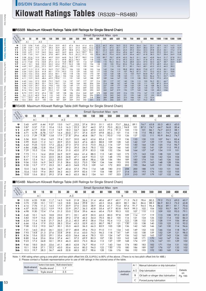
53
Note: 1. KW rating when using a one-pitch and two-pitch offset link (OL&2POL) is 80% of the above. (There is no two-pitch offset link for 48B.)2. Please contact a Tsubaki representative prior to use of kW ratings in the colored area of the table.
Drip lubrication
Number of chain strands Multi-strand factor1.72.5
B
C
Detailson
Pg. 193Oil bath or slinger disc lubrication
Forced pump lubrication
Lubricationmethod
Double strandTriple strand
Multi-strandfactor
A Manual lubrication or drip lubrication
B CA A
910111213
1415161718
1920212223
242526
10 15 20 30 40 50 70 100 150 200 250 300 350 400 450 500 550 600 650
5 10 15 20 25 30 40 50 60 80 100 125 150 175 200 250 300 350 400 450
B CA A
910111213
1415161718
1920212223
242526
■RS48B Maximum Kilowatt Ratings Table (kW Ratings for Single Strand Chain)
Small Sprocket Max rpmSmall Sprocket
No. of TeethLubrication Type
■RS40B Maximum Kilowatt Ratings Table (kW Ratings for Single Strand Chain)
Small Sprocket Max rpmSmall Sprocket
No. of TeethLubrication Type
B CA A10 25 50 100 150 200 250 300 350 400 450 500 550 600 650 700 750 800 850 900 1000 1100 1200 1300
910111213
1415161718
1920212223
2425262830
32354045
■RS32B Maximum Kilowatt Ratings Table (kW Ratings for Single Strand Chain)
Small Sprocket Max rpmSmall Sprocket
No. of TeethLubrication Type
3.45 3.87 4.29 4.71 5.13
5.56 5.99 6.42 6.86 7.29
7.73 8.17 8.61 9.06 9.50
10.0 10.4 10.8
4.97 5.57 6.17 6.78 7.39
8.01 8.63 9.25 9.88 10.5
11.1 11.8 12.4 13.0 13.7
14.3 15.0 15.6
6.44 7.21 8.00 8.78 9.58
10.4 11.2 12.0 12.8 13.6
14.4 15.3 16.1 16.9 17.7
18.6 19.4 20.2
9.27 10.4 11.5 12.7 13.8
14.9 16.1 17.3 18.4 19.6
20.8 22.0 23.2 24.3 25.5
26.7 28.0 29.2
12.0 13.5 14.9 16.4 17.9
19.4 20.9 22.4 23.9 25.4
26.9 28.5 30.0 31.5 33.1
34.7 36.2 37.8
14.7 16.5 18.2 20.0 21.8
23.7 25.5 27.3 29.2 31.0
32.9 34.8 36.7 38.6 40.5
42.4 44.3 46.2
19.9 22.3 24.7 27.1 29.6
32.0 34.5 37.0 39.5 42.0
44.6 47.1 49.6 52.2 54.8
57.3 59.9 62.5
27.4 30.7 34.0 37.4 40.8
44.2 47.6 51.0 54.5 57.9
61.4 64.9 68.4 72.0 75.5
79.0 82.6 86.2
39.5 44.2 49.0 53.9 58.7
63.6 68.5 73.5 78.5 83.5
88.5 93.5 98.6 104 109
114 119 124
51.1 57.3 63.5 69.8 76.1
82.4 88.8 95.2 102 108
115 121 128 134 141
148 154 161
62.5 70.0 77.6 85.3 93.0
101 109 116 124 132
140 148 156 164 172
180 188 197
73.7 82.5 91.5 101 110
119 128 137 146 156
165 175 184 193 203
210 217 223
84.6 94.8 105 116 126
136 145 153 160 168
175 182 189 195 202
208 214 219
89.1 101 110 118 127
135 142 150 157 164
171 177 183 189 195
200 205 210
74.7 87.5 101 115 122
130 137 144 150 157
163 168 174 179 184
188 193 197
63.8 74.7 86.1 98.2 111
123 129 135 141 147
152 156 161 165 169
173 176 179
55.3 64.7 74.7 85.1 95.9
107 119 125 129 134
138 142 145 148 151
153 155 157
48.5 56.8 65.5 74.7 84.2
94.1 104 112 115 119
122 124 126 128 130
131 132 132
43.0 50.4 58.1 66.2 74.7
83.4 92.5 96.7 99.2 101
103 104 105 106 106
105 105 104
3.35 3.75 4.16 4.57 4.98
5.40 5.82 6.24 6.66 7.08
7.51 7.93 8.36 8.80 9.23
9.66 10.1 10.5
6.25 7.00 7.76 8.53 9.30
10.1 10.9 11.6 12.4 13.2
14.0 14.8 15.6 16.4 17.2
18.0 18.8 19.7
9.00 10.1 11.2 12.3 13.4
14.5 15.6 16.8 17.9 19.0
20.2 21.3 22.5 23.6 24.8
26.0 27.1 28.3
11.7 13.1 14.5 15.9 17.4
18.8 20.3 21.7 23.2 24.7
26.1 27.6 29.1 30.6 32.1
33.6 35.2 36.7
14.3 16.0 17.7 19.5 21.2
23.0 24.8 26.5 28.3 30.1
32.0 33.8 35.6 37.4 39.3
41.1 43.0 44.8
16.8 18.8 20.9 22.9 25.0
27.1 29.2 31.3 33.4 35.5
37.7 39.8 42.0 44.1 46.3
48.5 50.6 52.8
21.8 24.4 27.0 29.7 32.4
35.1 37.8 40.5 43.3 46.0
48.8 51.6 54.4 57.2 60.0
62.8 65.6 68.5
26.6 29.8 33.0 36.3 39.6
42.9 46.2 49.5 52.9 56.3
59.6 63.0 66.4 69.9 73.3
76.7 80.2 83.7
31.4 35.1 38.9 42.8 46.6
50.5 54.4 58.4 62.3 66.3
70.3 74.3 78.3 82.3 86.4
90.4 94.5 98.6
40.6 45.5 50.4 55.4 60.4
65.5 70.5 75.6 80.7 85.9
91.0 96.2 101 107 112
117 122 128
49.7 55.6 61.7 67.7 73.9
80.0 86.2 92.4 98.7 105
111 118 124 130 137
143 150 156
60.7 68.0 75.4 82.8 90.3
97.8 105 113 121 128
134 141 147 153 159
164 170 176
71.5 80.1 87.6 94.9 102
109 116 123 130 136
143 149 156 162 168
174 180 186
76.2 84.1 91.7 99.3 107
114 121 128 135 142
149 155 162 168 174
180 186 192
78.6 86.6 94.5 102 110
117 124 132 138 145
152 158 165 171 177
183 189 195
80.5 88.5 96.4 104 112
119 126 133 140 146
152 159 165 170 176
182 187 192
79.2 86.9 94.4 102 109
115 122 128 135 141
146 152 157 162 167
171 176 180
75.2 82.3 89.1 95.7 102
108 114 119 125 130
134 139 143 147 151
154 157 160
69.0 75.2 81.1 86.7 92.0
97.0 102 106 110 114
118 121 124 126 129
131 133 134
60.7 65.8 70.6 75.0 79.1
82.9 86.3 89.4 92.2 94.6
96.7 98.5 100 101 102
102 102 102
2.222.492.763.033.30
3.583.854.134.414.69
4.975.265.545.836.11
6.406.696.987.568.14
8.739.6
11.1 12.6
5.06 5.67 6.29 6.91 7.53
8.16 8.79 9.42 10.1 10.7
11.3 12.0 12.6 13.3 13.9
14.6 15.3 15.9 17.2 18.6
19.9 21.9 25.3 28.8
9.45 10.6 11.7 12.9 14.1
15.2 16.4 17.6 18.8 20.0
21.2 22.4 23.6 24.8 26.0
27.2 28.5 29.7 32.2 34.7
37.2 40.9 47.3 53.7
17.6 19.7 21.9 24.0 26.2
28.4 30.6 32.8 35.0 37.3
39.5 41.8 44.0 46.3 48.6
50.8 53.1 55.4 60.0 64.7
69.4 76.4 88.3 100
25.4 28.4 31.5 34.6 37.8
40.9 44.1 47.3 50.5 53.7
56.9 60.1 63.4 66.7 69.9
73.2 76.5 79.8 86.5 93.2
100 110 127 144
32.9 36.9 40.8 44.9 48.9
53.0 57.1 61.2 65.4 69.5
73.7 77.9 82.1 86.4 90.6
94.9 99.1 103 112 121
129 143 165 187
40.2 45.1 49.9 54.9 59.8
64.8 69.8 74.8 79.9 85.0
90.1 95.2 100 106 111
116 121 126 137 148
158 174 201 229
47.4 53.1 58.8 64.6 70.5
76.3 82.3 88.2 94.2 100
106 112 118 124 131
137 143 149 161 174
186 205 237 269
54.4 61.0 67.6 74.3 81.0
87.7 94.5 101 108 115
122 129 136 143 150
157 164 171 185 200
214 236 273 310
61.4 68.8 76.2 83.7 91.3
98.9 107 114 122 130
138 145 153 161 169
177 185 193 209 225
242 266 307 342
62.5 73.2 84.4 93.1 102
110 118 127 136 144
153 162 170 179 188
197 206 215 232 250
269 296 318 331
53.3 62.5 72.1 82.1 92.6
103 115 126 138 151
164 177 187 197 207
216 226 236 256 269
278 291 306 314
46.2 54.1 62.5 71.2 80.2
89.7 100 110 120 131
142 153 165 177 189
201 214 227 251 260
268 278 289 293
40.6 47.5 54.8 62.5 70.4
78.7 87.3 96.2 105 115
124 134 145 155 166
177 188 199 223 247
255 262 268 266
36.0 42.1 48.6 55.4 62.5
69.8 77.4 85.3 93.4 102
110 119 128 138 147
157 167 177 197 219
239 243 243 235
32.2 37.7 43.5 49.6 55.9
62.5 69.3 76.3 83.6 91.1
98.8 107 115 123 132
140 149 158 177 196
216 221 215 201
29.0 34.0 39.2 44.7 50.4
56.3 62.5 68.8 75.4 82.1
89.0 96.2 103 111 119
126 134 143 159 177
195 195 184 163
26.4 30.9 35.6 40.6 45.7
51.1 56.7 62.5 68.4 74.5
80.8 87.3 93.9 101 108
115 122 129 145 160
174 168 150 121
24.1 28.2 32.5 37.0 41.8
46.7 51.8 57.0 62.5 68.1
73.8 79.7 85.8 92.0 98.3
105 111 118 132 146
147 137 112 76.2
22.1 25.9 29.8 34.0 38.3
42.8 47.5 52.3 57.3 62.5
67.7 73.2 78.7 84.4 90.2
96.2 102 108 121 125
119 105 72.6 28.4
18.9 22.1 25.5 29.0 32.7
36.6 40.6 44.7 48.9 53.3
57.8 62.5 67.2 72.1 77.0
82.1 87.3 86.3 78.2 68.0
55.7 33.3
16.3 19.1 22.1 25.2 28.4
31.7 35.2 38.7 42.4 46.2
50.1 54.1 57.4 53.7 49.5
44.7 39.4 33.4 19.8 3.84
14.3 16.8 19.4 22.1 24.9
27.8 30.9 34.0 32.1 28.3
23.8 18.8 13.1 6.77
12.7 14.9 17.2 16.8 13.8
10.1 5.67 0.57
BS/DIN Standard RS Roller Chains
Kilowatt Ratings Tables(RS32B~RS48B)Befo
re Use
Standard R
oller Chains
Lube-Free Roller C
hainsH
eavy Duty R
oller Chains
Corrosion Resistant Roller ChainsS
pecialty Roller C
hainsS
pro
cketsP
in G
ear Drives
Accesso
riesS
election
Han
dlin
g
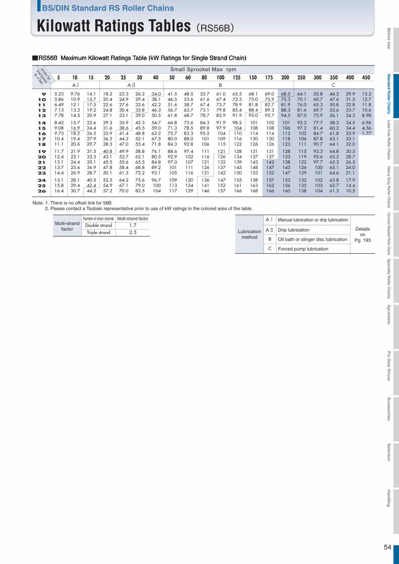
54
Note: 1. There is no offset link for 56B. 2. Please contact a Tsubaki representative prior to use of kW ratings in the colored area of the table.
Drip lubrication
Number of chain strands Multi-strand factor1.72.5
B
C
Detailson
Pg. 193Oil bath or slinger disc lubrication
Forced pump lubrication
Lubricationmethod
Double strandTriple strand
Multi-strandfactor
A Manual lubrication or drip lubrication
B CA A5 10 15 20 25 30 40 50 60 80 100 125 150 175 200 250 300 350 400 450
910111213
1415161718
1920212223
242526
Small Sprocket Max rpmSmall Sprocket
No. of TeethLubrication Type
■RS56B Maximum Kilowatt Ratings Table (kW Ratings for Single Strand Chain)
5.23 5.86 6.49 7.13 7.78
8.42 9.08 9.73 10.4 11.1
11.7 12.4 13.1 13.7 14.4
15.1 15.8 16.4
9.76 10.9 12.1 13.3 14.5
15.7 16.9 18.2 19.4 20.6
21.9 23.1 24.4 25.6 26.9
28.1 29.4 30.7
14.1 15.7 17.5 19.2 20.9
22.6 24.4 26.2 27.9 29.7
31.5 33.3 35.1 36.9 38.7
40.5 42.4 44.2
18.2 20.4 22.6 24.8 27.1
29.3 31.6 33.9 36.2 38.5
40.8 43.1 45.5 47.8 50.1
52.5 54.9 57.2
22.3 24.9 27.6 30.4 33.1
35.9 38.6 41.4 44.2 47.0
49.9 52.7 55.6 58.4 61.3
64.2 67.1 70.0
26.2 29.4 32.6 35.8 39.0
42.3 45.5 48.8 52.1 55.4
58.8 62.1 65.5 68.8 72.2
75.6 79.0 82.5
34.0 38.1 42.2 46.3 50.5
54.7 59.0 63.2 67.5 71.8
76.1 80.5 84.8 89.2 93.1
96.7 100 104
41.5 46.5 51.6 56.7 61.8
66.8 71.3 75.7 80.0 84.3
88.6 92.9 97.0 101 105
109 113 117
48.5 53.6 58.7 63.7 68.7
73.6 78.5 83.3 88.0 92.8
97.4 102 107 111 116
120 124 129
55.7 61.6 67.4 73.1 78.7
84.3 89.8 95.2 101 106
111 116 121 126 131
136 141 146
61.0 67.4 73.7 79.8 85.9
91.9 97.9 104 109 115
121 126 132 137 142
147 152 157
65.5 72.3 78.9 85.4 91.9
98.2 104 110 116 122
128 134 139 145 150
155 161 166
68.1 75.0 81.8 88.4 95.0
101 108 114 120 126
131 137 143 148 153
158 163 168
69.0 75.9 82.7 89.3 95.7
102 108 114 120 126
131 137 142 147 152
157 162 166
68.5 75.3 81.9 88.3 94.5
101 106 112 118 123
128 133 138 143 147
152 156 160
64.1 70.1 76.0 81.6 87.0
92.2 97.2 102 106 111
115 119 122 126 129
132 135 138
55.8 60.7 65.3 69.7 73.9
77.7 81.4 84.7 87.8 90.7
93.3 95.6 97.7 100 101
102 103 104
44.2 47.6 50.8 53.6 56.1
58.3 60.2 61.8 63.1 64.1
64.8 65.2 65.3 65.1 64.6
63.8 62.7 61.3
29.9 31.5 32.8 33.7 34.3
34.5 34.4 33.9 33.1 32.0
30.5 28.7 26.5 24.0 21.1
17.9 14.4 10.5
13.2 12.7 11.8 10.6 8.98
6.96 4.56 1.77
BS/DIN Standard RS Roller Chains
Kilowatt Ratings Tables(RS56B) Befo
re Use
Standard R
oller Chains
Lube-Free Roller C
hainsH
eavy Duty R
oller Chains
Corrosion Resistant Roller ChainsS
pecialty Roller C
hainsS
pro
cketsP
in G
ear Drives
Accesso
riesS
election
Han
dlin
g
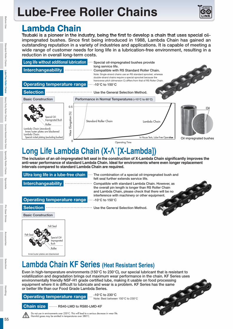
55
Lambda Chain
Lube-Free Roller Chains
Long Life Lambda Chain (X-Λ [X-Lambda])
Lambda Chain KF Series (Heat Resistant Series)
decrease in wear life.
Oil impregnated bushes
Oil
The inclusion of an oil-impregnated felt seal in the construction of X-Lambda Chain significantly improves the anti-wear performance of standard Lambda Chain. Ideal for environments where even longer replacement intervals compared to standard Lambda Chain are required.
Befo
re Use
Standard R
oller Chains
Lube-Free Roller C
hainsH
eavy Duty R
oller Chains
Corrosion Resistant Roller ChainsS
pecialty Roller C
hainsS
pro
cketsP
in G
ear Drives
Accesso
riesS
election
Han
dlin
g
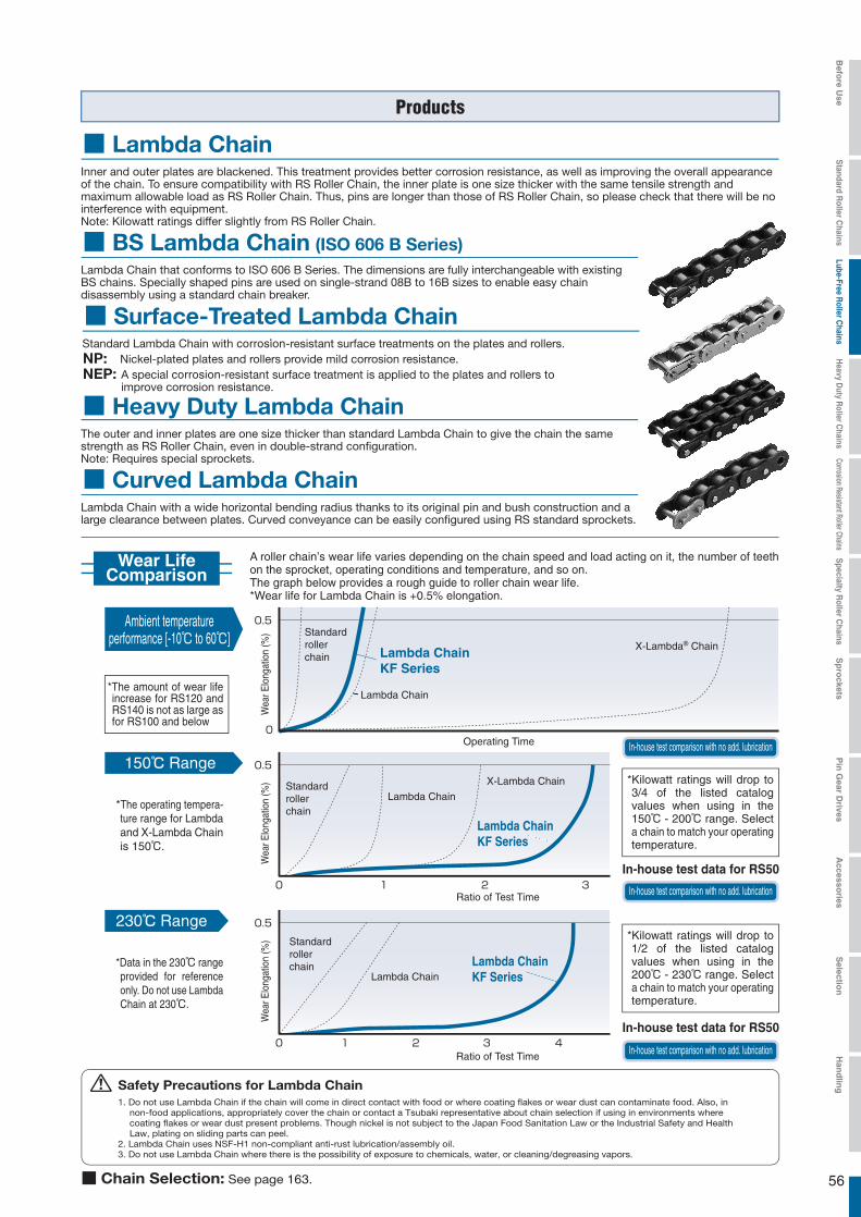
56163.
Wear LifeComparison
150℃ Range
230℃ Range
*The amount of wear life increase for RS120 and RS140 is not as large as for RS100 and below
*The operating tempera-ture range for Lambda and X-Lambda Chain is 150℃.
*Data in the 230℃ range provided for reference only. Do not use Lambda Chain at 230℃.
*Kilowatt ratings will drop to 3/4 of the listed catalog values when using in the 150℃ - 200℃ range. Select a chain to match your operating temperature.
*Kilowatt ratings will drop to 1/2 of the listed catalog values when using in the 200℃ - 230℃ range. Select a chain to match your operating temperature.
A roller chain’s wear life varies depending on the chain speed and load acting on it, the number of teeth on the sprocket, operating conditions and temperature, and so on.The graph below provides a rough guide to roller chain wear life.*Wear life for Lambda Chain is +0.5% elongation.
Ambient temperatureperformance [-10℃ to 60℃]
Wea
r Elo
ngat
ion
(%) Standard
roller chain Lambda Chain
KF Series
Lambda Chain
X-Lambda® Chain
Operating Time
In-house test comparison with no add. lubrication
In-house test comparison with no add. lubrication
In-house test comparison with no add. lubrication
0 1 2 3
Wea
r Elo
ngat
ion
(%) Standard
roller chain
Lambda Chain KF Series
Lambda Chain
X-Lambda Chain
Ratio of Test Time
In-house test data for RS50
In-house test data for RS500 1 2 3 4
Wea
r Elo
ngat
ion
(%) Standard
roller chain Lambda Chain
KF SeriesLambda Chain
Ratio of Test Time
corrosion
corrosion
Befo
re Use
Standard R
oller Chains
Lube-Free Roller C
hainsH
eavy Duty R
oller Chains
Corrosion Resistant Roller ChainsS
pecialty Roller C
hainsS
pro
cketsP
in G
ear Drives
Accesso
riesS
election
Han
dlin
g
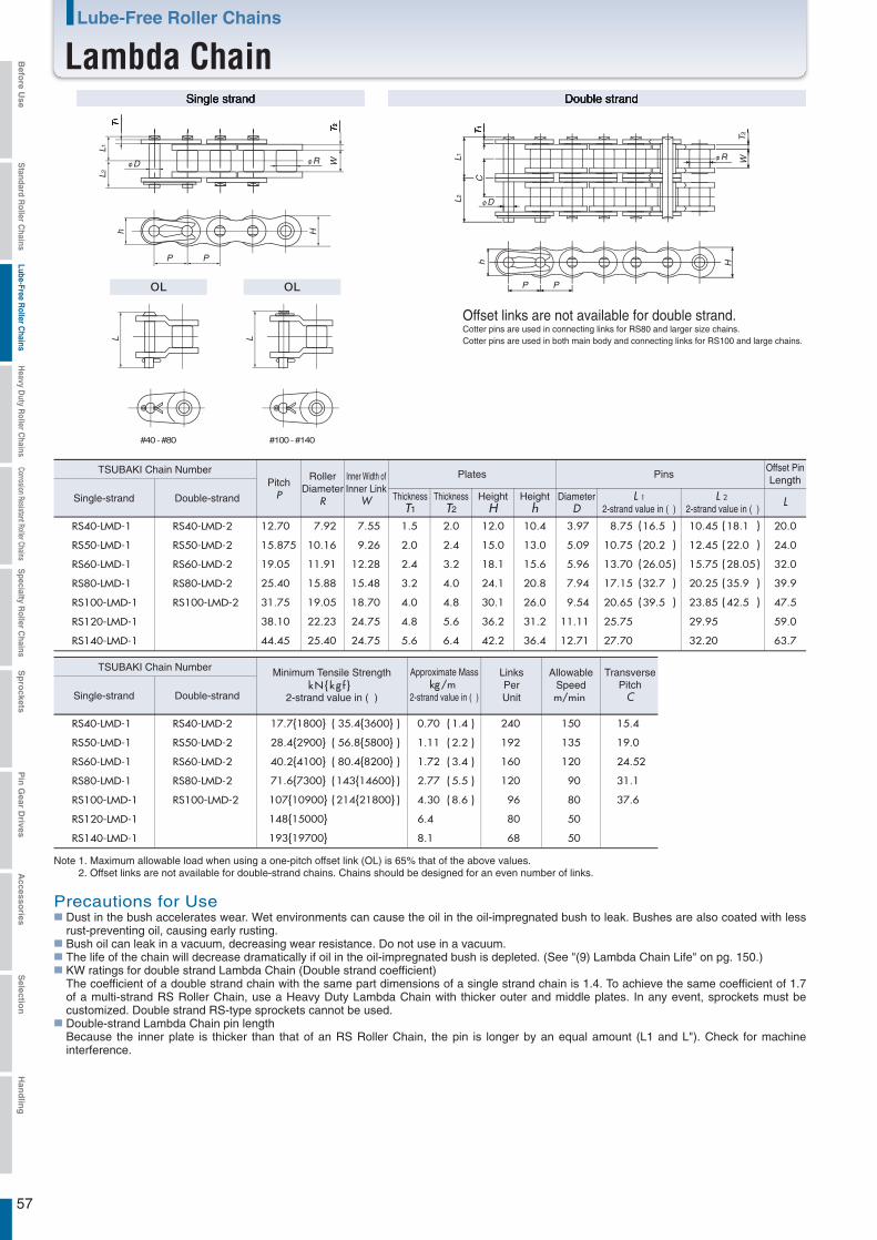
57
#40 - #80 #100 - #140
RS40-LMD-1 12.70 7.92 7.55 1.5 2.0 12.0 10.4 3.97 8.75 10.45 20.0
RS50-LMD-1 15.875 10.16 9.26 2.0 2.4 15.0 13.0 5.09 10.75 12.45 24.0
RS60-LMD-1 19.05 11.91 12.28 2.4 3.2 18.1 15.6 5.96 13.70 15.75 32.0
RS80-LMD-1 25.40 15.88 15.48 3.2 4.0 24.1 20.8 7.94 17.15 20.25 39.9
RS100-LMD-1 31.75 19.05 18.70 4.0 4.8 30.1 26.0 9.54 20.65 23.85 47.5
RS120-LMD-1 38.10 22.23 24.75 4.8 5.6 36.2 31.2 11.11 25.75 29.95 59.0
RS140-LMD-1
RS40-LMD-1
RS50-LMD-1
RS60-LMD-1
RS80-LMD-1
RS100-LMD-1
RS120-LMD-1
RS140-LMD-1
RS40-LMD-2
RS50-LMD-2
RS60-LMD-2
RS80-LMD-2
RS100-LMD-2
RS40-LMD-2
RS50-LMD-2
RS60-LMD-2
RS80-LMD-2
RS100-LMD-2
44.45 25.40 24.75 5.6 6.4 42.2 36.4 12.71 27.70 32.20
16.5 18.1
20.2 22.0
26.05 28.05
32.7 35.9
39.5 42.5
63.7
kN{kg f }
17.7{1800}
kg/m
0.70 240 150
28.4{2900} 1.11 192 135
40.2{4100} 1.72 160 120
71.6{7300} 2.77 120 90
107{10900} 4.30 96 80
148{15000} 6.4 80 50
193{19700}
35.4{( )3600}
( )
( )
( )
(
(
(
(
(
()
)
)
)
)
)
(
(
(
(
(
(
(
(
(
(
)
)
)
)
)
)
)
)
)
)
56.8{5800}
80.4{8200}
143{14600}
214{21800}
8.1
1.4
2.2
3.4
5.5
8.6
68 50
15.4
19.0
24.52
31.1
37.6
PP
h H
L1T
1
T2
L2
WφRφD
L L
φR
T2
W
φD
CT
1
L1L2
PP
h H
Single strand Double strand
Offset links are not available for double strand.Cotter pins are used in connecting links for RS80 and larger size chains.Cotter pins are used in both main body and connecting links for RS100 and large chains.
LDouble-strandSingle-strand
TSUBAKI Chain NumberPitch
P
RollerDiameter
R
Inner Width ofInner Link
W
Plates Pins
DiameterD
L 12-strand value in ( )
L 2 2-strand value in ( )
Offset PinLength
ThicknessT1
ThicknessT2
HeightH
Heighth
Double-strandSingle-strand
TSUBAKI Chain Number Minimum Tensile Strength
2-strand value in ( )
Approximate Mass
2-strand value in ( )
TransversePitch
C
LinksPerUnit
AllowableSpeedm/min
Note 1. Maximum allowable load when using a one-pitch offset link (OL) is 65% that of the above values.2. Offset links are not available for double-strand chains. Chains should be designed for an even number of links.
Precautions for UseDust in the bush accelerates wear. Wet environments can cause the oil in the oil-impregnated bush to leak. Bushes are also coated with less rust-preventing oil, causing early rusting.Bush oil can leak in a vacuum, decreasing wear resistance. Do not use in a vacuum.The life of the chain will decrease dramatically if oil in the oil-impregnated bush is depleted. (See "(9) Lambda Chain Life" on pg. 150.)KW ratings for double strand Lambda Chain (Double strand coefficient)The coefficient of a double strand chain with the same part dimensions of a single strand chain is 1.4. To achieve the same coefficient of 1.7 of a multi-strand RS Roller Chain, use a Heavy Duty Lambda Chain with thicker outer and middle plates. In any event, sprockets must be customized. Double strand RS-type sprockets cannot be used.Double-strand Lambda Chain pin lengthBecause the inner plate is thicker than that of an RS Roller Chain, the pin is longer by an equal amount (L1 and L"). Check for machine interference.
Lube-Free Roller Chains
Lambda ChainBefo
re Use
Standard R
oller Chains
Lube-Free Roller C
hainsH
eavy Duty R
oller Chains
Corrosion Resistant Roller ChainsS
pecialty Roller C
hainsS
pro
cketsP
in G
ear Drives
Accesso
riesS
election
Han
dlin
g
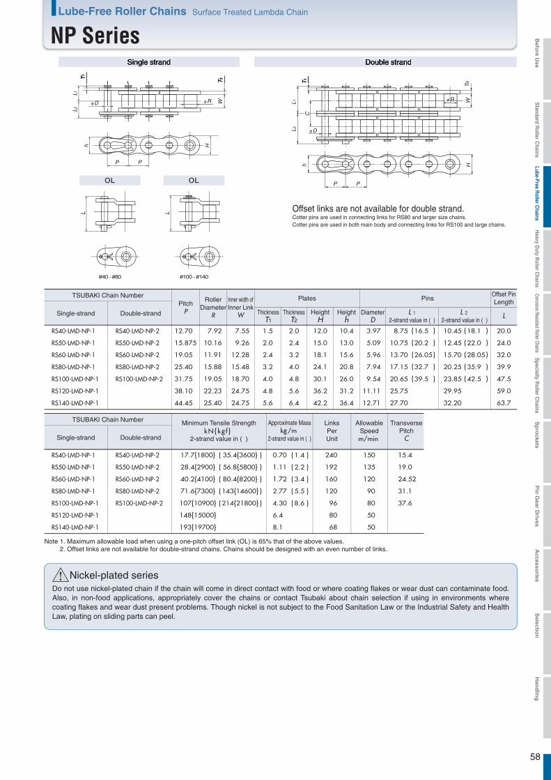
58
RS40-LMD-NP-1 12.70 7.92 7.55 1.5 2.0 12.0 10.4 3.97 8.75 10.45 20.0
RS50-LMD-NP-1 15.875 10.16 9.26 2.0 2.4 15.0 13.0 5.09 10.75 12.45 24.0
RS60-LMD-NP-1 19.05 11.91 12.28 2.4 3.2 18.1 15.6 5.96 13.70 15.70 32.0
RS80-LMD-NP-1 25.40 15.88 15.48 3.2 4.0 24.1 20.8 7.94 17.15 20.25 39.9
RS100-LMD-NP-1 31.75 19.05 18.70 4.0 4.8 30.1 26.0 9.54 20.65 23.85 47.5
RS120-LMD-NP-1 38.10 22.23 24.75 4.8 5.6 36.2 31.2 11.11 25.75 29.95 59.0
RS140-LMD-NP-1
RS40-LMD-NP-2
RS50-LMD-NP-2
RS60-LMD-NP-2
RS80-LMD-NP-2
RS100-LMD-NP-2
RS40-LMD-NP-1
RS50-LMD-NP-1
RS60-LMD-NP-1
RS80-LMD-NP-1
RS100-LMD-NP-1
RS120-LMD-NP-1
RS140-LMD-NP-1
RS40-LMD-NP-2
RS50-LMD-NP-2
RS60-LMD-NP-2
RS80-LMD-NP-2
RS100-LMD-NP-2
44.45 25.40 24.75 5.6 6.4 42.2 36.4 12.71 27.70 32.20
16.5 18.1
20.2 22.0
26.05 28.05
32.7 35.9
39.5 42.5
63.7
0.70 240 150
1.11 192 135
1.72 160 120
2.77 120 90
4.30 96 80
6.4 80 50
(
(
(
(
(
)
)
)
)
)
(
(
(
(
(
(
(
(
(
(
)
)
)
)
)
)
)
)
)
)
8.1
1.4
2.2
3.4
5.5
8.6
68 50
15.4
19.0
24.52
31.1
37.6
! Nickel-plated seriesDo not use nickel-plated chain if the chain will come in direct contact with food or where coating flakes or wear dust can contaminate food. Also, in non-food applications, appropriately cover the chains or contact Tsubaki about chain selection if using in environments where coating flakes and wear dust present problems. Though nickel is not subject to the Food Sanitation Law or the Industrial Safety and Health Law, plating on sliding parts can peel.
#40 - #80 #100 - #140
PP
h H
L1T
1
T2
L2
WφRφD
PP
h H
T1
T2
L1L2
C
WφR
φD
L L
Single strand Double strand
kN{kg f } kg/m
Note 1. Maximum allowable load when using a one-pitch offset link (OL) is 65% that of the above values.2. Offset links are not available for double-strand chains. Chains should be designed with an even number of links.
LDouble-strandSingle-strand
TSUBAKI Chain NumberPitch
P
RollerDiameter
R
Inner width ofInner Link
W
Plates Pins
DiameterD
L 12-strand value in ( )
L 2 2-strand value in ( )
Offset PinLength
ThicknessT1
ThicknessT2
HeightH
Heighth
Double-strandSingle-strand
TSUBAKI Chain Number Approximate Mass
2-strand value in ( )
LinksPerUnit
AllowableSpeedm/min
Minimum Tensile Strength
2-strand value in ( )
TransversePitch
C
Offset links are not available for double strand.Cotter pins are used in connecting links for RS80 and larger size chains.Cotter pins are used in both main body and connecting links for RS100 and large chains.
Lube-Free Roller Chains Surface Treated Lambda Chain
NP Series
17.7{1800}
28.4{2900}
40.2{4100}
71.6{7300}
107{10900}
148{15000}
193{19700}
35.4{( )3600}
( )
( )
( )
( )
56.8{5800}
80.4{8200}
143{14600}
214{21800}
Befo
re Use
Standard R
oller Chains
Lube-Free Roller C
hainsH
eavy Duty R
oller Chains
Corrosion Resistant Roller ChainsS
pecialty Roller C
hainsS
pro
cketsP
in G
ear Drives
Accesso
riesS
election
Han
dlin
g
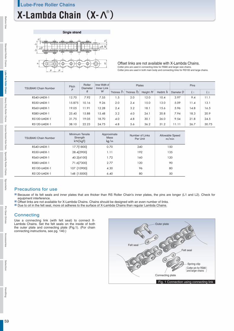
59
L 1 L 2
RS40-LMDX-1 12.70 7.92 7.55 1.5 2.0 12.0 10.4 3.97 99.4 11.1
RS50-LMDX-1 15.875 10.16 9.26 2.0 2.4 15.0 13.0 5.09 11.4 13.1
RS60-LMDX-1 19.05 11.91 12.28 2.4 3.2 18.1 15.6 5.96 14.8 16.5
RS80-LMDX-1 25.40 15.88 15.48 3.2 4.0 24.1 20.8 7.94 18.3 20.9
RS100-LMDX-1
RS40-LMDX-1
RS50-LMDX-1
RS60-LMDX-1
RS80-LMDX-1
RS100-LMDX-1
31.75 19.05 18.70 4.0 4.8 30.1 26.0 9.54 21.8 24.5
kN{kg f } kg/mm/min
17.7{1800} 0.70 240 150
28.4{2900} 1.11 192 135
40.2{4100} 1.72 160 120
71.6{7300} 2.77 120 190
107 {10900} 4.30 196 180
RS120-LMDX-1
RS120-LMDX-1
38.10 22.23 24.75 4.8 5.6 36.2 31.2 11.11 26.7 30.75
148 {15000} 6.40 80 50
Outer plate
Felt seal
Felt seal
Connecting plate
Spring clip
Cotter pin for RS80and larger chains
Fig. 1 Connection using connecting link
T1
T2
WφD φR
L1L2
H
PP
h
Single strand
TSUBAKI Chain Number
TSUBAKI Chain Number
PitchP
RollerDiameter
R
Inner Width ofInner Link
W
Plates Pins
Diameter DThickness T1 Thickness T2 Height H Heibht h
Number of LinksPer Unit
Allowable Speed
ConnectingUse a connecting link (with felt seal) to connect X- Lambda Chains. Set the felt seals on the inside of both the outer plate and connecting plate (Fig.1). (For chain connecting instructions, see pg. 140.)
Precautions for useBecause of its felt seals and inner plates that are thicker than RS Roller Chain’s inner plates, the pins are longer (L1 and L2). Check for equipment interference.Offset links are not available for X-Lambda Chains. Chains should be designed with an even number of links.Due to oil in the felt seal, more oil adheres to the surface of X-Lambda Chains than regular Lambda Chains.
ApproximateMass
Minimum TensileStrength
Offset links are not available with X-Lambda Chains.Cotter pins are used in connecting links for RS80 and larger size chains.Cotter pins are used in both main body and connecting links for RS100 and large chains.
Lube-Free Roller Chains
X-Lambda Chain(X-Λ )Befo
re Use
Standard R
oller Chains
Lube-Free Roller C
hainsH
eavy Duty R
oller Chains
Corrosion Resistant Roller ChainsS
pecialty Roller C
hainsS
pro
cketsP
in G
ear Drives
Accesso
riesS
election
Han
dlin
g
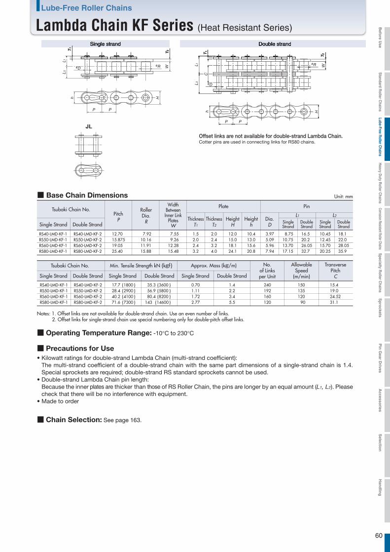
60
Single strand Double strand
163.
Lube-Free Roller Chains
Lambda Chain KF Series (Heat Resistant Series) Befo
re Use
Standard R
oller Chains
Lube-Free Roller C
hainsH
eavy Duty R
oller Chains
Corrosion Resistant Roller ChainsS
pecialty Roller C
hainsS
pro
cketsP
in G
ear Drives
Accesso
riesS
election
Han
dlin
g
plates are those
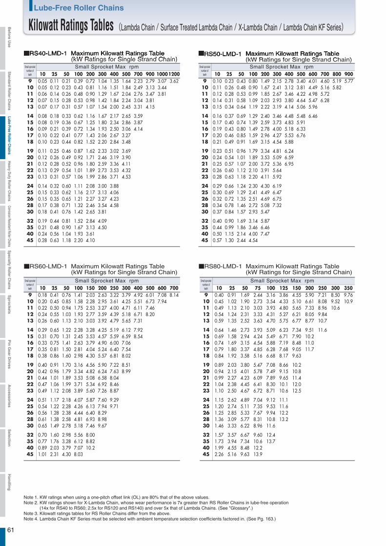
61
Small sprocketnumber of
teeth
Small Sprocket Max rpm10 25 50 100 200 300 400 500 700 900 10001200
9 0.05 0.11 0.21 0.39 0.72 1.04 1.35 1.64 2.23 2.79 3.07 3.6210 0.05 0.12 0.23 0.43 0.81 1.16 1.51 1.84 2.49 3.13 3.4411 0.06 0.14 0.26 0.48 0.90 1.29 1.67 2.04 2.76 3.47 3.8112 0.07 0.15 0.28 0.53 0.98 1.42 1.84 2.24 3.04 3.8113 0.07 0.17 0.31 0.57 1.07 1.54 2.00 2.45 3.31 4.15
14 0.08 0.18 0.33 0.62 1.16 1.67 2.17 2.65 3.5915 0.08 0.19 0.36 0.67 1.25 1.80 2.34 2.86 3.8716 0.09 0.21 0.39 0.72 1.34 1.93 2.50 3.06 4.1417 0.10 0.22 0.41 0.77 1.43 2.06 2.67 3.2718 0.10 0.23 0.44 0.82 1.52 2.20 2.84 3.48
19 0.11 0.25 0.46 0.87 1.62 2.33 3.02 3.6920 0.12 0.26 0.49 0.92 1.71 2.46 3.19 3.9021 0.12 0.28 0.52 0.96 1.80 2.59 3.36 4.1122 0.13 0.29 0.54 1.01 1.89 2.73 3.53 4.3223 0.13 0.31 0.57 1.06 1.99 2.86 3.71 4.53
24 0.14 0.32 0.60 1.11 2.08 3.00 3.8825 0.15 0.33 0.62 1.16 2.17 3.13 4.0626 0.15 0.35 0.65 1.21 2.27 3.27 4.2328 0.17 0.38 0.71 1.32 2.46 3.54 4.5830 0.18 0.41 0.76 1.42 2.65 3.81
32 0.19 0.44 0.81 1.52 2.84 4.0935 0.21 0.48 0.90 1.67 3.13 4.5040 0.24 0.56 1.04 1.93 3.6145 0.28 0.63 1.18 2.20 4.10
Small sprocketnumber of
teeth
Small Sprocket Max rpm10 25 50 100 200 300 400 500 600 700 800 900
9 0.10 0.23 0.43 0.80 1.49 2.15 2.78 3.40 4.01 4.60 5.19 5.7710 0.11 0.26 0.48 0.90 1.67 2.41 3.12 3.81 4.49 5.16 5.8211 0.12 0.28 0.53 0.99 1.85 2.67 3.46 4.22 4.98 5.7212 0.14 0.31 0.58 1.09 2.03 2.93 3.80 4.64 5.47 6.2813 0.15 0.34 0.64 1.19 2.22 3.19 4.14 5.06 5.96
14 0.16 0.37 0.69 1.29 2.40 3.46 4.48 5.48 6.4615 0.17 0.40 0.74 1.39 2.59 3.73 4.83 5.9116 0.19 0.43 0.80 1.49 2.78 4.00 5.18 6.3317 0.20 0.46 0.85 1.59 2.96 4.27 5.53 6.7618 0.21 0.49 0.91 1.69 3.15 4.54 5.88
19 0.23 0.51 0.96 1.79 3.34 4.81 6.2420 0.24 0.54 1.01 1.89 3.53 5.09 6.5921 0.25 0.57 1.07 2.00 3.72 5.36 6.9522 0.26 0.60 1.12 2.10 3.91 5.6423 0.28 0.63 1.18 2.20 4.11 5.92
24 0.29 0.66 1.24 2.30 4.30 6.1925 0.30 0.69 1.29 2.41 4.49 6.4726 0.32 0.72 1.35 2.51 4.69 6.7528 0.34 0.78 1.46 2.72 5.08 7.3230 0.37 0.84 1.57 2.93 5.47
32 0.40 0.90 1.69 3.14 5.8735 0.44 0.99 1.86 3.46 6.4640 0.50 1.15 2.14 4.00 7.4745 0.57 1.30 2.44 4.54
Small sprocketnumber of
teeth
Small Sprocket Max rpm10 25 50 100 150 200 250 300 400 500 600 700
9 0.18 0.41 0.76 1.41 2.03 2.63 3.22 3.79 4.92 6.01 7.08 8.1410 0.20 0.45 0.85 1.58 2.28 2.95 3.61 4.25 5.51 6.73 7.9411 0.22 0.50 0.94 1.75 2.53 3.27 4.00 4.71 6.11 7.4612 0.24 0.55 1.03 1.93 2.77 3.59 4.39 5.18 6.71 8.2013 0.26 0.60 1.13 2.10 3.03 3.92 4.79 5.65 7.31
14 0.29 0.65 1.22 2.28 3.28 4.25 5.19 6.12 7.9215 0.31 0.70 1.31 2.45 3.53 4.57 5.59 6.59 8.5416 0.33 0.75 1.41 2.63 3.79 4.90 6.00 7.0617 0.35 0.81 1.50 2.81 4.04 5.24 6.40 7.5418 0.38 0.86 1.60 2.98 4.30 5.57 6.81 8.02
19 0.40 0.91 1.70 3.16 4.56 5.90 7.22 8.5120 0.42 0.96 1.79 3.34 4.82 6.24 7.63 8.9921 0.44 1.01 1.89 3.53 5.08 6.58 8.0422 0.47 1.06 1.99 3.71 5.34 6.92 8.4623 0.49 1.12 2.08 3.89 5.60 7.26 8.87
24 0.51 1.17 2.18 4.07 5.87 7.60 9.2925 0.54 1.22 2.28 4.26 6.13 7.94 9.7126 0.56 1.28 2.38 4.44 6.40 8.2928 0.61 1.38 2.58 4.81 6.93 8.9830 0.65 1.49 2.78 5.18 7.46 9.67
32 0.70 1.60 2.98 5.56 8.0035 0.77 1.76 3.28 6.12 8.8240 0.89 2.03 3.79 7.07 10.245 1.01 2.31 4.30 8.03
Small sprocketnumber of
teeth
Small Sprocket Max rpm10
9 0.4010111213
1415161718
1920212223
2425262830
32354045
25 50 75 100 125 150 200 250 300 3500.91 1.69 2.44 3.16 3.86 4.55 5.90 7.21 8.50 9.76
0.45 1.02 1.90 2.73 3.54 4.33 5.10 6.61 8.08 9.52 10.90.49 1.13 2.10 3.03 3.93 4.80 5.65 7.33 8.96 10.60.54 1.24 2.31 3.33 4.31 5.27 6.21 8.05 9.840.59 1.35 2.52 3.63 4.70 5.75 6.77 8.77 10.7
0.64 1.46 2.73 3.93 5.09 6.23 7.34 9.51 11.60.69 1.58 2.94 4.24 5.49 6.71 7.90 10.20.74 1.69 3.15 4.54 5.88 7.19 8.48 11.00.79 1.80 3.37 4.85 6.28 7.68 9.05 11.70.84 1.92 3.58 5.16 6.68 8.17 9.63
0.89 2.03 3.80 5.47 7.08 8.66 10.20.94 2.15 4.01 5.78 7.49 9.15 10.80.99 2.27 4.23 6.09 7.89 9.65 11.41.04 2.38 4.45 6.41 8.30 10.1 12.01.10 2.50 4.67 6.72 8.71 10.6 12.5
1.15 2.62 4.89 7.04 9.12 11.11.20 2.74 5.11 7.35 9.53 11.61.25 2.85 5.33 7.67 9.94 12.21.36 3.09 5.77 8.31 10.8 13.21.46 3.33 6.22 8.96 11.6
1.57 3.57 6.67 9.60 12.41.73 3.94 7.34 10.6 13.71.99 4.55 8.48 12.22.26 5.16 9.63 13.9
Note 1. KW ratings when using a one-pitch offset link (OL) are 80% that of the above values.Note 2. KW ratings shown for X-Lambda Chain, whose wear performance is 7x greater than RS Roller Chains in lube-free operation
(14x for RS40 to RS60; 2.5x for RS120 and RS140) and over 5x that of Lambda Chains. (See "Glossary".)Note 3. Kilowatt ratings tables for RS Roller Chains differ from the above.Note 4. Lambda Chain KF Series must be selected with ambient temperature selection coefficients factored in. (See Pg. 163.)
RS40-LMD-1 Maximum Kilowatt Ratings Table (kW Ratings for Single Strand Chain)
RS60-LMD-1 Maximum Kilowatt Ratings Table (kW Ratings for Single Strand Chain)
RS80-LMD-1 Maximum Kilowatt Ratings Table (kW Ratings for Single Strand Chain)
RS50-LMD-1 Maximum Kilowatt Ratings Table (kW Ratings for Single Strand Chain)
Lube-Free Roller Chains
Kilowatt Ratings Tables (Lambda Chain / Surface Treated Lambda Chain / X-Lambda Chain / Lambda Chain KF Series)Befo
re Use
Standard R
oller Chains
Lube-Free Roller C
hainsH
eavy Duty R
oller Chains
Corrosion Resistant Roller ChainsS
pecialty Roller C
hainsS
pro
cketsP
in G
ear Drives
Accesso
riesS
election
Han
dlin
g
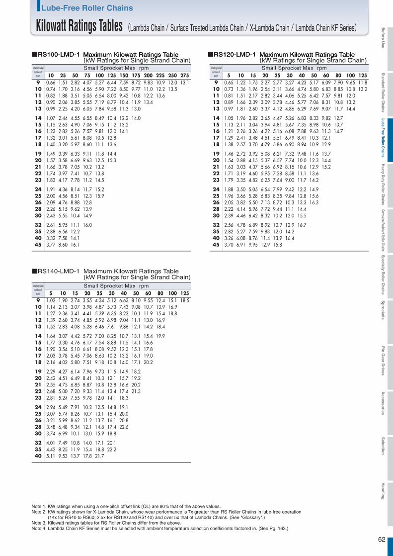
62
10 25 50 75 100 125 150 175 200 225 250 2759 0.66 1.51 2.82 4.07 5.27 6.44 7.59 8.72 9.83 10.9 12.0 13.110 0.74 1.70 3.16 4.56 5.90 7.22 8.50 9.77 11.0 12.2 13.511 0.82 1.88 3.51 5.05 6.54 8.00 9.42 10.8 12.2 13.612 0.90 2.06 3.85 5.55 7.19 8.79 10.4 11.9 13.413 0.99 2.25 4.20 6.05 7.84 9.58 11.3 13.0
14 1.07 2.44 4.55 6.55 8.49 10.4 12.2 14.015 1.15 2.63 4.90 7.06 9.15 11.2 13.216 1.23 2.82 5.26 7.57 9.81 12.0 14.117 1.32 3.01 5.61 8.08 10.5 12.818 1.40 3.20 5.97 8.60 11.1 13.6
19 1.49 3.39 6.33 9.11 11.8 14.420 1.57 3.58 6.69 9.63 12.5 15.321 1.66 3.78 7.05 10.2 13.222 1.74 3.97 7.41 10.7 13.823 1.83 4.17 7.78 11.2 14.5
24 1.91 4.36 8.14 11.7 15.225 2.00 4.56 8.51 12.3 15.926 2.09 4.76 8.88 12.828 2.26 5.15 9.62 13.930 2.43 5.55 10.4 14.9
32 2.61 5.95 11.1 16.035 2.88 6.56 12.240 3.32 7.58 14.145 3.77 8.60 16.1
5 10 15 20 25 30 40 50 60 80 100 1259 0.65 1.22 1.75 2.27 2.77 3.27 4.23 5.17 6.09 7.90 9.65 11.8
10 0.73 1.36 1.96 2.54 3.11 3.66 4.74 5.80 6.83 8.85 10.8 13.211 0.81 1.51 2.17 2.82 3.44 4.06 5.25 6.42 7.57 9.81 12.012 0.89 1.66 2.39 3.09 3.78 4.46 5.77 7.06 8.31 10.8 13.213 0.97 1.81 2.60 3.37 4.12 4.86 6.29 7.69 9.07 11.7 14.4
14 1.05 1.96 2.82 3.65 4.47 5.26 6.82 8.33 9.82 12.715 1.13 2.11 3.04 3.94 4.81 5.67 7.35 8.98 10.6 13.716 1.21 2.26 3.26 4.22 5.16 6.08 7.88 9.63 11.3 14.717 1.29 2.41 3.48 4.51 5.51 6.49 8.41 10.3 12.118 1.38 2.57 3.70 4.79 5.86 6.90 8.94 10.9 12.9
19 1.46 2.72 3.92 5.08 6.21 7.32 9.48 11.6 13.720 1.54 2.88 4.15 5.37 6.57 7.74 10.0 12.3 14.421 1.63 3.03 4.37 5.66 6.92 8.15 10.6 12.9 15.222 1.71 3.19 4.60 5.95 7.28 8.58 11.1 13.623 1.79 3.35 4.82 6.25 7.64 9.00 11.7 14.2
24 1.88 3.50 5.05 6.54 7.99 9.42 12.2 14.925 1.96 3.66 5.28 6.83 8.35 9.84 12.8 15.626 2.05 3.82 5.50 7.13 8.72 10.3 13.3 16.328 2.22 4.14 5.96 7.72 9.44 11.1 14.430 2.39 4.46 6.42 8.32 10.2 12.0 15.5
32 2.56 4.78 6.89 8.92 10.9 12.9 16.735 2.82 5.27 7.59 9.83 12.0 14.240 3.26 6.08 8.76 11.4 13.9 16.445 3.70 6.91 9.95 12.9 15.8
5 10 15 20 25 30 40 50 60 80 100 1259 1.02 1.90 2.74 3.55 4.34 5.12 6.63 8.10 9.55 12.4 15.1 18.510 1.14 2.13 3.07 3.98 4.87 5.73 7.43 9.08 10.7 13.9 16.911 1.27 2.36 3.41 4.41 5.39 6.35 8.23 10.1 11.9 15.4 18.812 1.39 2.60 3.74 4.85 5.92 6.98 9.04 11.1 13.0 16.913 1.52 2.83 4.08 5.28 6.46 7.61 9.86 12.1 14.2 18.4
14 1.64 3.07 4.42 5.72 7.00 8.25 10.7 13.1 15.4 19.915 1.77 3.30 4.76 6.17 7.54 8.88 11.5 14.1 16.616 1.90 3.54 5.10 6.61 8.08 9.52 12.3 15.1 17.817 2.03 3.78 5.45 7.06 8.63 10.2 13.2 16.1 19.018 2.16 4.02 5.80 7.51 9.18 10.8 14.0 17.1 20.2
19 2.29 4.27 6.14 7.96 9.73 11.5 14.9 18.220 2.42 4.51 6.49 8.41 10.3 12.1 15.7 19.221 2.55 4.75 6.85 8.87 10.8 12.8 16.6 20.222 2.68 5.00 7.20 9.33 11.4 13.4 17.4 21.323 2.81 5.24 7.55 9.78 12.0 14.1 18.3
24 2.94 5.49 7.91 10.2 12.5 14.8 19.125 3.07 5.74 8.26 10.7 13.1 15.4 20.026 3.21 5.99 8.62 11.2 13.7 16.1 20.828 3.48 6.48 9.34 12.1 14.8 17.4 22.630 3.74 6.99 10.1 13.0 15.9 18.8
32 4.01 7.49 10.8 14.0 17.1 20.135 4.42 8.25 11.9 15.4 18.8 22.240 5.11 9.53 13.7 17.8 21.7
RS100-LMD-1 Maximum Kilowatt Ratings Table (kW Ratings for Single Strand Chain)
RS120-LMD-1 Maximum Kilowatt Ratings Table (kW Ratings for Single Strand Chain)
RS140-LMD-1 Maximum Kilowatt Ratings Table (kW Ratings for Single Strand Chain)
Small sprocketnumber of
teeth
Small Sprocket Max rpm
Small sprocketnumber of
teeth
Small Sprocket Max rpm Small sprocketnumber of
teeth
Small Sprocket Max rpm
Note 1. KW ratings when using a one-pitch offset link (OL) are 80% that of the above values.Note 2. KW ratings shown for X-Lambda Chain, whose wear performance is 7x greater than RS Roller Chains in lube-free operation
(14x for RS40 to RS60; 2.5x for RS120 and RS140) and over 5x that of Lambda Chains. (See "Glossary".)Note 3. Kilowatt ratings tables for RS Roller Chains differ from the above.Note 4. Lambda Chain KF Series must be selected with ambient temperature selection coefficients factored in. (See Pg. 163.)
Lube-Free Roller Chains
Kilowatt Ratings Tables (Lambda Chain / Surface Treated Lambda Chain / X-Lambda Chain / Lambda Chain KF Series) Befo
re Use
Standard R
oller Chains
Lube-Free Roller C
hainsH
eavy Duty R
oller Chains
Corrosion Resistant Roller ChainsS
pecialty Roller C
hainsS
pro
cketsP
in G
ear Drives
Accesso
riesS
election
Han
dlin
g
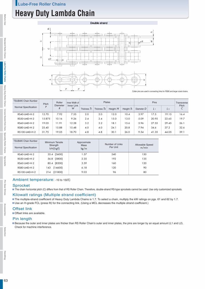
63
RS40-LMD-H-2 12.70 7.92 7.55 2.0 12.0 10.4 3.97 17.5 19.15
RS50-LMD-H-2 15.875 10.16 9.26
2.0
2.4 15.0 13.0 5.09 20.95 22.65
RS60-LMD-H-2 19.05 11.91 12.28
2.4
3.2 18.1 15.6 5.96 27.55 29.45
RS80-LMD-H-2 25.40 15.88 15.48
3.2
4.0 24.1 20.8 7.94 34.6 37.2
RS100-LMD-H-2 31.75 19.05 18.70
4.0
4.8 4.8 30.1 26.0 9.54 41.35 44.05
16.4
19.7
26.1
32.6
39.1
RS40-LMD-H-2
RS50-LMD-H-2
RS60-LMD-H-2
RS80-LMD-H-2
RS100-LMD-H-2
kN{kg f } kg/m m/min
1.57 240 150
2.35 192 135
3.59 160 120
6.18 120 90
9.03 96 80
L1
T1
T2
W
Hh
L 2
C
P P
φR
Double strand
Cotter pins are used in connecting links for RS80 and larger sized chains.
L 1 L 2
TSUBAKI Chain Number
TSUBAKI Chain Number
PitchP
RollerDiameter
R
Inner Width ofInner Link
W
Plates Pins
Diameter DThickness T1 Thickness T2 Height H Height h
Number of LinksPer Unit
Allowable Speed
Normal Specification
Normal Specification
Ambient temperature: -10 to 150℃
The chain horizontal pitch (C) differs from that of RS Roller Chain. Therefore, double-strand RS-type sprockets cannot be used. Use only customized sprockets.
Pin lengthBecause the outer and inner plates are thicker than RS Roller Chain’s outer and inner plates, the pins are longer by an equal amount (L1 and L2).Check for machine interference.
Sprocket
Kilowatt ratings (Multiple strand coefficient)The multiple-strand coefficient of Heavy Duty Lambda Chains is 1.7. To select a chain, multiply the kW ratings on pgs. 61 and 62 by 1.7.Use an H-grade FCL (press fit) for the connecting link. (Using a MCL decreases the multiple strand coefficient.)
Offset linkOffset links are available.
TransversePitch
C
Minimum TensileStrength
ApproximateMass
Lube-Free Roller Chains
Heavy Duty Lambda Chain
35.4 {3600}
56.8 {5800}
80.4 {8200}
143
214 {21800}
{14600}
φD
Befo
re Use
Standard R
oller Chains
Lube-Free Roller C
hainsH
eavy Duty R
oller Chains
Corrosion Resistant Roller ChainsS
pecialty Roller C
hainsS
pro
cketsP
in G
ear Drives
Accesso
riesS
election
Han
dlin
g

64
RS40-LMD-H-NP-2 12.70 7.92 7.55 2.0 12.0 10.4 3.97 17.5 19.15
RS50-LMD-H-NP-2 15.875 10.16 9.26
2.0
2.4 15.0 13.0 5.09 20.95 22.65
RS60-LMD-H-NP-2 19.05 11.91 12.28
2.4
3.2 18.1 15.6 5.96 27.55 29.45
RS80-LMD-H-NP-2 25.40 15.88 15.48
3.2
4.0 24.1 20.8 7.94 34.6 37.2
RS100-LMD-H-NP-2
RS40-LMD-H-NP-2
RS50-LMD-H-NP-2
RS60-LMD-H-NP-2
RS80-LMD-H-NP-2
RS100-LMD-H-NP-2
31.75 19.05 18.70
4.0
4.8 4.8 30.1 26.0 9.54 41.35 44.05
16.4
19.7
26.1
32.6
39.1
kN{kg f } kg/m m/min
1.57 240 150
2.35 192 135
3.59 160 120
6.18 120 90
9.03 96 80
Double strand
L1
T1
T2
WHh
L 2
C
P P
φR
TSUBAKI Chain Number
Nickel-platedSpecification
TSUBAKI Chain Number
Nickel-platedSpecification
PitchP
RollerDiameter
R
Inner Width ofInner Link
W
Plates
L 1 L 2
Pins
Diameter DThickness T1 Thickness T2 Height H Height h
Number of LinksPer Unit
Allowable Speed
TransversePitch
C
Minimum TensileStrength
ApproximateMass
Cotter pins are used in connecting links for RS80 and larger sized chains.
Ambient temperature: -10 to 150℃
The chain horizontal pitch (C) differs from that of RS Roller Chain. Therefore, double-strand RS-type sprockets cannot be used. Use only customized sprockets.
Pin lengthBecause the outer and inner plates are thicker than RS Roller Chain’s outer and inner plates, the pins are longer by an equal amount (L1 and L2).Check for machine interference with equipment in use.
Sprocket
Kilowatt ratings (Multiple strand coefficient)The multiple-strand coefficient of Heavy Duty Lambda Chains is 1.7. To select a chain, multiply the kW ratings on pgs. 61 and 62 by 1.7.Use an H-grade FCL (press fit) for the connecting link. (Using a MCL decreases the multiple strand coefficient.)
Offset linkOffset links are available.
Lube-Free Roller Chains Surface Treated Lambda Chain
Heavy Duty Lambda Chain NP Series
35.4 {3600}
56.8 {5800}
80.4 {8200}
143
214 {21800}
{14600}
φD
Befo
re Use
Standard R
oller Chains
Lube-Free Roller C
hainsH
eavy Duty R
oller Chains
Corrosion Resistant Roller ChainsS
pecialty Roller C
hainsS
pro
cketsP
in G
ear Drives
Accesso
riesS
election
Han
dlin
g
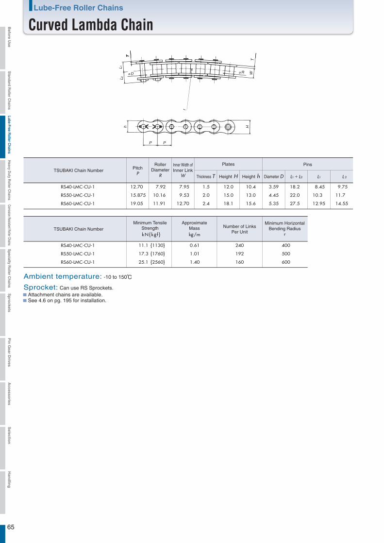
65
RS40-LMC-CU-1
RS50-LMC-CU-1
RS60-LMC-CU-1
RS40-LMC-CU-1
RS50-LMC-CU-1
RS60-LMC-CU-1
7.95
9.53
12.70
12.0 10.4 3.59 8.45 9.751.5
15.0 13.0 4.45 10.3 11.72.0
18.1 15.6 5.35 12.95
18.2
22.0
27.5 14.552.4
TSUBAKI Chain Number
12.70 7.92
15.875 10.16
19.05 11.91
TSUBAKI Chain Number
11.1 {1130} 0.61 240 400
17.3 {1760} 1.01 192 500
25.1 {2560} 1.40 160 600
T
TWφD φR
L1
r
L2
H
PP
h
Attachment chains are available.See 4.6 on pg. 195 for installation.
PitchP
RollerDiameter
R
Inner Width ofInner Link
W
Plates Pins
Diameter DThickness T Height H Height h L1+L2 L1 L 2
kN{kg f } kg/m
Number of LinksPer Unit
Minimum HorizontalBending Radius
r
Ambient temperature: -10 to 150℃
Sprocket: Can use RS Sprockets.
Minimum TensileStrength
ApproximateMass
Lube-Free Roller Chains
Curved Lambda ChainBefo
re Use
Standard R
oller Chains
Lube-Free Roller C
hainsH
eavy Duty R
oller Chains
Corrosion Resistant Roller ChainsS
pecialty Roller C
hainsS
pro
cketsP
in G
ear Drives
Accesso
riesS
election
Han
dlin
g
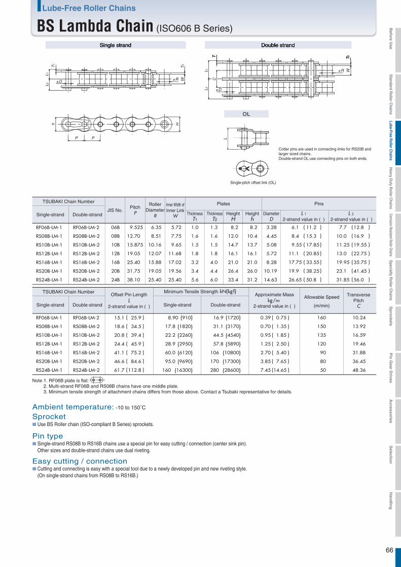
66
Double strandSingle strand
6.35 5.72 1.0 8.2 8.2
8.51 7.75 1.6 12.0 10.4
10.16 9.65 1.5 14.7 13.7
12.07 11.68 1.8 16.1 16.1
9.525
12.70
15.875
19.05
25.40
31.75
38.10
06B
08B
10B
12B
16B
20B
24B
15.88
19.05
25.40
17.02
19.56
25.40
1.3
1.6
1.5
1.8
4.0
4.4
6.0
3.2
3.4
5.6
21.0
26.4
33.4
21.0
26.0
31.2
3.28
4.45
5.08
5.72
8.28
10.19
14.63
Single-strand RS08B to RS16B chains use a special pin for easy cutting / connection (center sink pin).Other sizes and double-strand chains use dual riveting.
Pin type
Cutting and connecting is easy with a special tool due to a newly developed pin and new riveting style.(On single-strand chains from RS08B to RS16B.)
Easy cutting / connection
6.1 11.2
8.4 15.3
9.55 17.85
11.1 20.85
17.75 33.55
19.9 38.25
26.65 50.8
7.7 12.8
10.0 16.9
11.25 19.55
13.0 22.75
19.95 35.75
23.1 41.45
31.85 56.0
15.1 25.9
18.6 34.5
20.8 39.4
24.4 45.9
41.1 75.2
46.6 84.6
61.7 112.8
8.90 {910} 0.39 0.75
17.8 {1820} 31.1 {3170}
16.9 {1720}
0.70 1.35
22.2 {2260} 44.5 {4540}
28.9 {2950} 57.8 {5890}
60.0 {6120} 106 {10800}
170 {17300}95.0 {9690}
160 {16300} 280 {28600}
0.95 1.85
1.25 2.50
2.70 5.40
3.85 7.65
7.45 14.65
T1
T1
T2
WH
φD
φD
PP
h
φR
T2
WφR
L1L2
L1L2
C
L
TSUBAKI Chain Number
Single-strand Double-strand
RF06B-LM-1
RS08B-LM-1
RS10B-LM-1
RS12B-LM-1
RS16B-LM-1
RS20B-LM-1
RS24B-LM-1
RF06B-LM-2
RS08B-LM-2
RS10B-LM-2
RS12B-LM-2
RS16B-LM-2
RS20B-LM-2
RS24B-LM-2
RF06B-LM-1
RS08B-LM-1
RS10B-LM-1
RS12B-LM-1
RS16B-LM-1
RS20B-LM-1
RS24B-LM-1
RF06B-LM-2
RS08B-LM-2
RS10B-LM-2
RS12B-LM-2
RS16B-LM-2
RS20B-LM-2
RS24B-LM-2
JIS No.
Single-strand Double-strand
kN{kg f}
(
(
(
(
(
)
)
)
)
)
( )
(
(
(
(
(
(
(
(
(
(
(
(
(
(
(
(
(
(
(
(
(
(
)
)
)
)
)
)
)
)
)
)
)
)
)
)
)
)
)
)
)
)
)
)
kg/m
TSUBAKI Chain Number
Single-strand Double-strand
Cotter pins are used in connecting links for RS20B andlarger sized chains.Double-strand OL use connecting pins on both ends.
Single-pitch offset link (OL)
PitchP
RollerDiameter
R
Inner Width ofInner Link
W
Plates
ThicknessT1
ThicknessT2
HeightH
Heighth
Pins
DiameterD
L 12-strand value in ( )
L 2 2-strand value in ( )
Offset Pin LengthL
2-strand value in ( )
Approximate Mass
2-strand value in ( )
160
150
135
120
90
80
50
Allowable Speed
(m/min)
10.24
13.92
16.59
19.46
31.88
36.45
48.36
TransversePitch
C
Note 1. RF06B plate is flat: 2. Multi-strand RF06B and RS08B chains have one middle plate.3. Minimum tensile strength of attachment chains differs from those above. Contact a Tsubaki representative for details.
Ambient temperature: -10 to 150˚C
Use BS Roller chain (ISO-compliant B Series) sprockets.Sprocket
Minimum Tensile Strength
Lube-Free Roller Chains
BS Lambda Chain (ISO606 B Series) Befo
re Use
Standard R
oller Chains
Lube-Free Roller C
hainsH
eavy Duty R
oller Chains
Corrosion Resistant Roller ChainsS
pecialty Roller C
hainsS
pro
cketsP
in G
ear Drives
Accesso
riesS
election
Han
dlin
g

67
Note 1. KW ratings when using a one-pitch offset link (OL) are 80% that of the above values.2. Kilowatt ratings tables for BS Roller Chains differ from the above.
Small sprocketnumber of
teeth
Small Sprocket Max rpm
RF06B-LM-1 Maximum Kilowatt Ratings Table (kW Ratings for Single Strand Chain)
Small sprocketnumber of
teeth
Small Sprocket Max rpm
RS08B-LM-1 Maximum Kilowatt Ratings Table (kW Ratings for Single Strand Chain)
Small sprocketnumber of
teeth
Small Sprocket Max rpm
RS10B-LM-1 Maximum Kilowatt Ratings Table (kW Ratings for Single Strand Chain)
Small sprocketnumber of
teeth
Small Sprocket Max rpm
RS12B-LM-1 Maximum Kilowatt Ratings Table (kW Ratings for Single Strand Chain)
Number of chain strands Multi-strand factor
1.4Double strandMulti-strand
factor
Lube-Free Roller Chains
Kilowatt Ratings Tables(BS Lambda Chain [ISO 606 B Series])Befo
re Use
Standard R
oller Chains
Lube-Free Roller C
hainsH
eavy Duty R
oller Chains
Corrosion Resistant Roller ChainsS
pecialty Roller C
hainsS
pro
cketsP
in G
ear Drives
Accesso
riesS
election
Han
dlin
g

68
Small sprocketnumber of
teeth
Small Sprocket Max rpm
RS16B-LM-1 Maximum Kilowatt Ratings Table (kW Ratings for Single Strand Chain)
Small sprocketnumber of
teeth
Small Sprocket Max rpm
RS20B-LM-1 Maximum Kilowatt Ratings Table (kW Ratings for Single Strand Chain)
Small sprocketnumber of
teeth
Small Sprocket Max rpm
RS24B-LM-1 Maximum Kilowatt Ratings Table (kW Ratings for Single Strand Chain)
Note 1. KW ratings when using a one-pitch offset link (OL) are 80% that of the above values.2. Kilowatt ratings tables for BS Roller Chains differ from the above.
Number of chain strands Multi-strand factor
1.4Double strandMulti-strand
factor
Lube-Free Roller Chains
Kilowatt Ratings Tables(BS Lambda Chain [ISO 606 B Series]) Befo
re Use
Standard R
oller Chains
Lube-Free Roller C
hainsH
eavy Duty R
oller Chains
Corrosion Resistant Roller ChainsS
pecialty Roller C
hainsS
pro
cketsP
in G
ear Drives
Accesso
riesS
election
Han
dlin
g
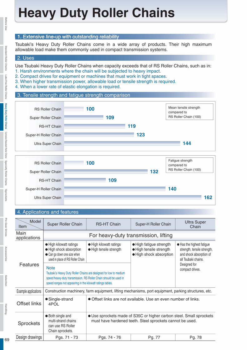
2. Uses
Tsubaki’s Heavy Duty Roller Chains come in a wide array of products. Their high maximum allowable load make them commonly used in compact transmission systems.
Use Tsubaki Heavy Duty Roller Chains when capacity exceeds that of RS Roller Chains, such as in:1. Harsh environments where the chain will be subjected to heavy impact.2. Compact drives for equipment or machines that must work in tight spaces.3. When higher transmission power, allowable load or tensile strength is required.4. When a lower rate of elastic elongation is required.
1. Extensive line-up with outstanding reliability
4. Applications and features
Sprockets
Example applications
For heavy-duty transmission, lifting
Offset links
Design drawings Pgs. 71 - 73 Pgs. 74 - 76 Pg. 77 Pg. 78
Ultra SuperChain
Super-H Roller ChainRS-HT ChainSuper Roller Chain
High kilowatt ratingsHigh shock absorptionCan go down one size whenused in place of RS Roller Chain
Both single andmulti-strand chainscan use RS RollerChain sprockets.
Construction machinery, farm equipment, lifting mechanisms, port equipment, parking structures, etc.
Single-strand4POL
Offset links are not available. Use an even number of links.
High kilowatt ratingsHigh tensile strength
Use sprockets made of S35C or higher carbon steel. Small sprocketsmust have hardened teeth. Steel sprockets cannot be used.
High fatigue strengthHigh tensile strengthHigh shock absorption
Has the highest fatigue strength, tensile strength,and shock absorption ofall Tsubaki chains.Designed forcompact drives.
ItemModel
Mainapplications
FeaturesNoteTsubaki’s Heavy Duty Roller Chains are designed for low to mediumspeed heavy-duty transmission. RS Roller Chain should be used inspeed ranges not appearing in the kilowatt ratings tables.
69
Heavy Duty Roller Chains
3. Tensile strength and fatigue strength comparison
Super Roller Chain
RS-HT Chain
Super-H Roller Chain
Ultra Super Chain
109
119
123
144
132
RS Roller Chain 100
100
109
140
162
Fatigue strengthcompared toRS Roller Chain (100)
Super Roller Chain
RS-HT Chain
Super-H Roller Chain
Ultra Super Chain
RS Roller Chain
Mean tensile strengthcompared toRS Roller Chain (100)
Befo
re Use
Standard R
oller Chains
Lube-Free Roller C
hainsH
eavy Duty R
oller Chains
Corrosion Resistant Roller ChainsS
pecialty Roller C
hainsS
pro
cketsP
in G
ear Drives
Accesso
riesS
election
Han
dlin
g
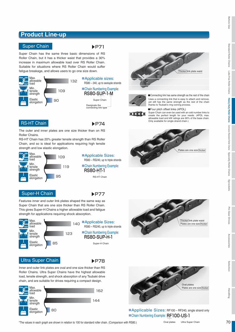
70
■Applicable Sizes:
■Chain Numbering Example:
RS60 – RS240, up to triple strands
■Applicable Sizes:
■Chain Numbering Example:
RS80 – RS240, up to triple strands140
123
85
162
144
80
Thicker link plate waistPlates are one size thicker
Oval platesPlates are one size thicker
●Connecting link has same strength as the rest of the chain
●Four pitch offset links (4POL)
*The values in each graph are shown in relation to 100 for standard roller chain. (Comparison with RS80.)
132
109
90
109
119
95
Plates are one size thicker
Thicker link plate waist
■Applicable sizes:
■Chain Numbering Example:
Super Chain
Designate the connecting link type
RS80-SUP-1-M
RS80 – 240, up to sextuple strands
RS-HT Chain
RS80-HT-1
Super-H Chain
RS80-SUP-H-1
■Applicable Sizes:■Chain Numbering Example:
Ultra Super ChainOval plates
RF100-US-1RF100 – RF240, single strand only
▶P71
▶P74
▶P77
▶P78
Product Line-up
Super Chain
RS-HT Chain
Super-H Chain
Ultra Super Chain
Super Chain has the same three basic dimensions of RS Roller Chain, but it has a thicker waist that provides a 30% increase in maximum allowable load over RS Roller Chain. Suitable for situations where RS Roller Chain would suffer fatigue breakage, and allows users to go one size down.
The outer and inner plates are one size thicker than on RS Roller Chains.RS-HT Chain has 20% greater tensile strength than RS Roller Chain, and so is ideal for applications requiring high tensile strength and low elastic elongation.
Features inner and outer link plates shaped the same way as Super Chain that are one size thicker than RS Roller Chain. This gives Super-H Chains a higher allowable load and fatigue strength for applications requiring shock absorption.
Inner and outer link plates are oval and one size thicker than RS Roller Chains. Ultra Super Chains have the highest allowable load, tensile strength, and shock absorption of any Tsubaki drive chain, and are suitable for drives requiring a compact design.
Max. allowable load
Elastic elongation
Min. tensile strength
Max. allowable load
Elastic elongation
Min. tensile strength
Max. allowable load
Elastic elongation
Min. tensile strength
Max. allowable load
Elastic elongation
Min. tensile strength
Uses a connecting link that is easy to attach and remove, yet still has the same strength as the rest of the chain thanks to Tsubaki’s ring coining process.
Super Chain can even be used with an odd number links to create the perfect length for your needs. (4POL max. allowable load and kW ratings are 90% of the base chain. Only available for single strand chain.)
Befo
re Use
Standard R
oller Chains
Lube-Free Roller C
hainsH
eavy Duty R
oller Chains
Corrosion Resistant Roller ChainsS
pecialty Roller C
hainsS
pro
cketsP
in G
ear Drives
Accesso
riesS
election
Han
dlin
g
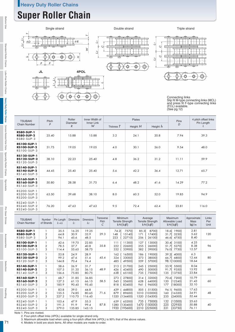
71
Heavy Duty Roller Chains
Super Roller Chain
4POLJL
RS80-SUP-1 1 16.25 19.2529.3
74.2{ 7570} 85.3{ 8700} 18.6{ 1900}RS80-SUP-2 2 30.9 33.9 148 { 15140} 171 { 17400} 31.7{ 3230} 120RS80-SUP-3
RS80-SUP-1RS80-SUP-2RS80-SUP-3
3 45.6 48.5 223 { 22710} 256 { 26100} 46.6{ 4750}
DimensionsL1
DimensionsL2
TransversePitchC
2.815.628.40
L2
L1
L2
L1
L2
L1
CC
L1
L1
hT
TW
H
P
R
P
LC
15.88 24.1 20.8 7.943.2 39.3
PitchP
RollerDiameter
R
Inner Width ofInner Link
W
4 pitch offset linksPin Length
L
Plates PinsD
D
Thickness T Height H Height h
25.40 15.88
RS100-SUP-1 1 19.75 22.8535.8
111 { 11300} 127 { 13000} 30.4{ 3100}RS100-SUP-2 2 37.7 40.8 222 { 22600} 255 { 26000} 51.7{ 5270} 96RS100-SUP-3
RS100-SUP-1RS100-SUP-2RS100-SUP-3
3 55.65 58.75 332 { 33900} 382 { 39000} 76.0{ 7750}
4.258.38
12.57
19.05 30.1 26.0 9.544.0 48.031.75 19.05
RS120-SUP-1 1 24.9 28.945.4
162 { 16500} 186 { 19000} 39.2{ 4000}RS120-SUP-2 2 47.6 51.6 324 { 33000} 373 { 38000} 66.7{ 6800} 80RS120-SUP-3
RS120-SUP-1RS120-SUP-2RS120-SUP-3
3 70.4 74.4 485 { 49500} 559 { 57000} 98.1{10000}
6.312.4418.64
25.40 36.2 31.2 11.114.8 59.938.10 22.23
RS140-SUP-1 1 26.9 31.748.9
213 { 21700} 245 { 25000} 53.9{ 5500}RS140-SUP-2 2 51.35 56.15 426 { 43400} 490 { 50000} 91.7{ 9350} 68RS140-SUP-3
RS140-SUP-1RS140-SUP-2RS140-SUP-3
3 75.85 80.75 638 { 65100} 735 { 75000} 135 {13750}
8.0415.9223.84
25.40 42.2 36.4 12.715.6 65.744.45 25.40
RS160-SUP-1 1 31.85 36.8558.5
273 { 27800} 314 { 32000} 70.6{ 7200}RS160-SUP-2 2 61.15 66.15 545 { 55600} 628 { 64000} 120 {12240} 60RS160-SUP-3
RS160-SUP-1RS160-SUP-2RS160-SUP-3
3 90.45 95.45 818 { 83400} 941 { 96000} 177 {18000}
10.7921.4332.10
31.75 48.2 41.6 14.296.4 77.250.80 28.58
RS200-SUP-1 1 39.0 44.871.6
439 { 44800} 505 { 51500} 94.1{ 9600}RS200-SUP-2 2 74.85 80.65 879 { 89600} 1010 {103000} 160 {16320} 48RS200-SUP-3
RS200-SUP-1RS200-SUP-2RS200-SUP-3
3 110.75 116.45 1320 {134400} 1520 {154500} 235 {24000}
17.6334.9152.44
38.10 60.3 52.0 19.858.0 94.963.50 39.68
RS240-SUP-1 1 47.9 55.587.8
639 { 65200} 735 { 75000} 132 {13500}RS240-SUP-2 2 91.9 99.4 1280 {130400} 1470 {150000} 225 {22950} 40RS240-SUP-3
RS240-SUP-1RS240-SUP-2RS240-SUP-3
3 135.85
35.564.894.1
Pin LengthL1+L2
42.678.5
114.4
53.899.2
144.8
58.6107.5156.6
68.7127.3185.9
83.8155.5227.2
103.4191.3279.0 143.15 1920 {195600} 2210 {225000} 331 {33750}
25.6350.8876.11
47.63 72.4 62.4 23.819.5 116.076.20 47.63
Triple strandSingle strand Double strand
TSUBAKIChain Number
TSUBAKIChain Number
Numberof Strands
MaximumAllowable Load
kN{kgf }
ApproximateMasskg/m
LinksPerUnit
MinimumTensile Strength
kN{kgf }
AverageTensile Strength
kN{kgf }
Note 1. Pins are riveted. 2. Four-pitch offset links (4POL) available for single strand only.3. Maximum allowable load when using a four-pitch offset link (4POL) is 90% that of the above values.4. Models in bold are stock items. All other models are made-to-order.
Connecting linksSlip fit M-type connecting links (MCL) and press fit F-type connecting links (FCL) available.(See pg.12)
Befo
re Use
Standard R
oller Chains
Lube-Free Roller C
hainsH
eavy Duty R
oller Chains
Corrosion Resistant Roller ChainsS
pecialty Roller C
hainsS
pro
cketsP
in G
ear Drives
Accesso
riesS
election
Han
dlin
g
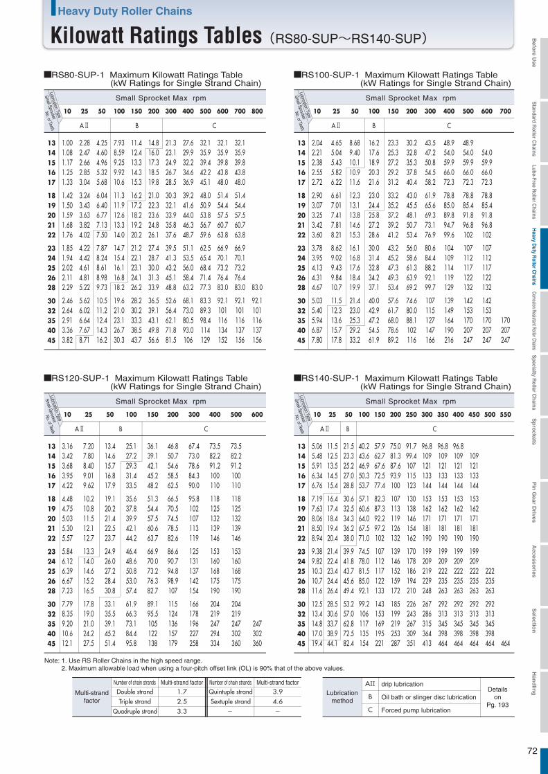
72
Heavy Duty Roller Chains
Kilowatt Ratings Tables(RS80-SUP~RS140-SUP)
B C
10 25 50 100 150 200 300 400 500 600 700
2.04 2.21 2.38 2.55 2.72
2.90 3.07 3.25 3.42 3.60
3.78 3.95 4.13 4.31 4.67
5.03 5.40 5.94 6.87 7.80
4.65 5.04 5.43 5.82 6.22
6.61 7.01 7.41 7.81 8.21
8.62 9.02 9.43 9.84 10.7
11.5 12.3 13.6 15.7 17.8
8.68 9.40 10.1 10.9 11.6
12.3 13.1 13.8 14.6 15.3
16.1 16.8 17.6 18.4 19.9
21.4 23.0 25.3 29.2 33.2
16.2 17.6 18.9 20.3 21.6
23.0 24.4 25.8 27.2 28.6
30.0 31.4 32.8 34.2 37.1
40.0 42.9 47.2 54.5 61.9
23.3 25.3 27.2 29.2 31.2
33.2 35.2 37.2 39.2 41.2
43.2 45.2 47.3 49.3 53.4
57.6 61.7 68.0 78.6 89.2
30.2 32.8 35.3 37.8 40.4
43.0 45.5 48.1 50.7 53.4
56.0 58.6 61.3 63.9 69.2
74.6 80.0 88.1 102 116
43.5 47.2 50.8 54.5 58.2
61.9 65.6 69.3 73.1 76.9
80.6 84.4 88.2 92.1 99.7
107 115 127 147 166
48.9 54.0 59.9 66.0 72.3
78.8 85.0 89.8 94.7 99.6
104 109 114 119 129
139 149 164 190 216
48.9 54.0 59.9 66.0 72.3
78.8 85.4 91.8 96.8 102
107 112 117 122 132
142 153 170 207 247
54.0 59.9 66.0 72.3
78.8 85.4 91.8 96.8 102
107 112 117 122 132
142 153 170 207 247
170 207 247
1314151617
1819202122
2324252628
3032354045
B C
10 25 50 100 150 200 300 400 500 600
3.16 3.42 3.68 3.95 4.22
4.48 4.75 5.03 5.30 5.57
5.84 6.12 6.39 6.67 7.23
7.79 8.35 9.20 10.6 12.1
7.20 7.80 8.40 9.01 9.62
10.2 10.8 11.5 12.1 12.7
13.3 14.0 14.6 15.2 16.5
17.8 19.0 21.0 24.2 27.5
13.4 14.6 15.7 16.8 17.9
19.1 20.2 21.4 22.5 23.7
24.9 26.0 27.2 28.4 30.8
33.1 35.5 39.1 45.2 51.4
25.1 27.2 29.3 31.4 33.5
35.6 37.8 39.9 42.1 44.2
46.4 48.6 50.8 53.0 57.4
61.9 66.3 73.1 84.4 95.8
36.1 39.1 42.1 45.2 48.2
51.3 54.4 57.5 60.6 63.7
66.9 70.0 73.2 76.3 82.7
89.1 95.5 105 122 138
46.8 50.7 54.6 58.5 62.5
66.5 70.5 74.5 78.5 82.6
86.6 90.7 94.8 98.9 107
115 124 136 157 179
67.4 73.0 78.6 84.3 90.0
95.8 102 107 113 119
125 131 137 142 154
166 178 196 227 258
73.5 82.2 91.2 100 110
118 125 132 139 146
153 160 168 175 190
204 219 247 294 334
73.5 82.2 91.2 100 110
118 125 132 139 146
153 160 168 175 190
204 219 247 302 360
247 302 360
1314151617
1819202122
2324252628
3032354045
B C
10 25 50 100 150 200 250 300 350 400 450 500 550
5.06 5.48 5.91 6.34 6.76
7.19 7.63 8.06 8.50 8.94
9.38 9.82 10.3 10.7 11.6
12.5 13.4 14.8 17.0 19.4
11.5 12.5 13.5 14.5 15.4
16.4 17.4 18.4 19.4 20.4
21.4 22.4 23.4 24.4 26.4
28.5 30.6 33.7 38.9 44.1
21.5 23.3 25.2 27.0 28.8
30.6 32.5 34.3 36.2 38.0
39.9 41.8 43.7 45.6 49.4
53.2 57.0 62.8 72.5 82.4
40.2 43.6 46.9 50.3 53.7
57.1 60.6 64.0 67.5 71.0
74.5 78.0 81.5 85.0 92.1
99.2 106 117 135 154
57.9 62.7 67.6 72.5 77.4
82.3 87.3 92.2 97.2 102
107 112 117 122 133
143 153 169 195 221
75.0 81.3 87.6 93.9 100
107 113 119 126 132
139 146 152 159 172
185 199 219 253 287
91.7 99.4 107 115 123
130 138 146 154 162
170 178 186 194 210
226 243 267 309 351
96.8 109 121 133 144
153 162 171 181 190
199 209 219 229 248
267 286 315 364 413
96.8 109 121 133 144
153 162 171 181 190
199 209 222 235 263
292 313 345 398 464
96.8 109 121 133 144
153 162 171 181 190
199 209 222 235 263
292 313 345 398 464
109 121 133 144
153 162 171 181 190
199 209 222 235 263
292 313 345 398 464
222 235 263
292 313 345 398 464 464
1314151617
1819202122
2324252628
3032354045
B C
10 25 50 100 150 200 300 400 500 600 700 800
1.00 1.08 1.17 1.25 1.33
1.42 1.50 1.59 1.68 1.76
1.85 1.94 2.02 2.11 2.29
2.46 2.64 2.91 3.36 3.82
2.28 2.47 2.66 2.85 3.04
3.24 3.43 3.63 3.82 4.02
4.22 4.42 4.61 4.81 5.22
5.62 6.02 6.64 7.67 8.71
4.25 4.60 4.96 5.32 5.68
6.04 6.40 6.77 7.13 7.50
7.87 8.24 8.61 8.98 9.73
10.5 11.2 12.4 14.3 16.2
7.93 8.59 9.25 9.92 10.6
11.3 11.9 12.6 13.3 14.0
14.7 15.4 16.1 16.8 18.2
19.6 21.0 23.1 26.7 30.3
11.4 12.4 13.3 14.3 15.3
16.2 17.2 18.2 19.2 20.2
21.2 22.1 23.1 24.1 26.2
28.2 30.2 33.3 38.5 43.7
14.8 16.0 17.3 18.5 19.8
21.0 22.3 23.6 24.8 26.1
27.4 28.7 30.0 31.3 33.9
36.5 39.1 43.1 49.8 56.6
21.3 23.1 24.9 26.7 28.5
30.3 32.1 33.9 35.8 37.6
39.5 41.3 43.2 45.1 48.8
52.6 56.4 62.1 71.8 81.5
27.6 29.9 32.2 34.6 36.9
39.2 41.6 44.0 46.3 48.7
51.1 53.5 56.0 58.4 63.2
68.1 73.0 80.5 93.0 106
32.1 35.9 39.4 42.2 45.1
48.0 50.9 53.8 56.7 59.6
62.5 65.4 68.4 71.4 77.3
83.3 89.3 98.4 114 129
32.1 35.9 39.8 43.8 48.0
51.4 54.4 57.5 60.7 63.8
66.9 70.1 73.2 76.4 83.0
92.1 101 116 134 152
32.1 35.9 39.8 43.8 48.0
51.4 54.4 57.5 60.7 63.8
66.9 70.1 73.2 76.4 83.0
92.1 101 116 137 156
83.0
92.1 101 116 137 156
1314151617
1819202122
2324252628
3032354045
Small Sprocket
No. of TeethLubrication Type
Small Sprocket Max rpm
RS100-SUP-1 Maximum Kilowatt Ratings Table (kW Ratings for Single Strand Chain)
Small Sprocket
No. of TeethLubrication Type
Small Sprocket Max rpm
RS80-SUP-1 Maximum Kilowatt Ratings Table (kW Ratings for Single Strand Chain)
Small Sprocket
No. of TeethLubrication Type
Small Sprocket Max rpm
RS120-SUP-1 Maximum Kilowatt Ratings Table (kW Ratings for Single Strand Chain)
Small Sprocket
No. of TeethLubrication Type
Small Sprocket Max rpm
RS140-SUP-1 Maximum Kilowatt Ratings Table (kW Ratings for Single Strand Chain)
Number of chain strandsNumber of chain strands Multi-strand factorMulti-strand factor1.7 3.92.5 4.63.3 - -
AII
B
C
drip lubricationDetails
onPg. 193
Oil bath or slinger disc lubrication
Forced pump lubrication
Lubricationmethod
Quintuple strandSextuple strand
Double strandTriple strand
Quadruple strand
Multi-strandfactor
Note: 1. Use RS Roller Chains in the high speed range.2. Maximum allowable load when using a four-pitch offset link (OL) is 90% that of the above values.
Befo
re Use
Standard R
oller Chains
Lube-Free Roller C
hainsH
eavy Duty R
oller Chains
Corrosion Resistant Roller ChainsS
pecialty Roller C
hainsS
pro
cketsP
in G
ear Drives
Accesso
riesS
election
Han
dlin
g
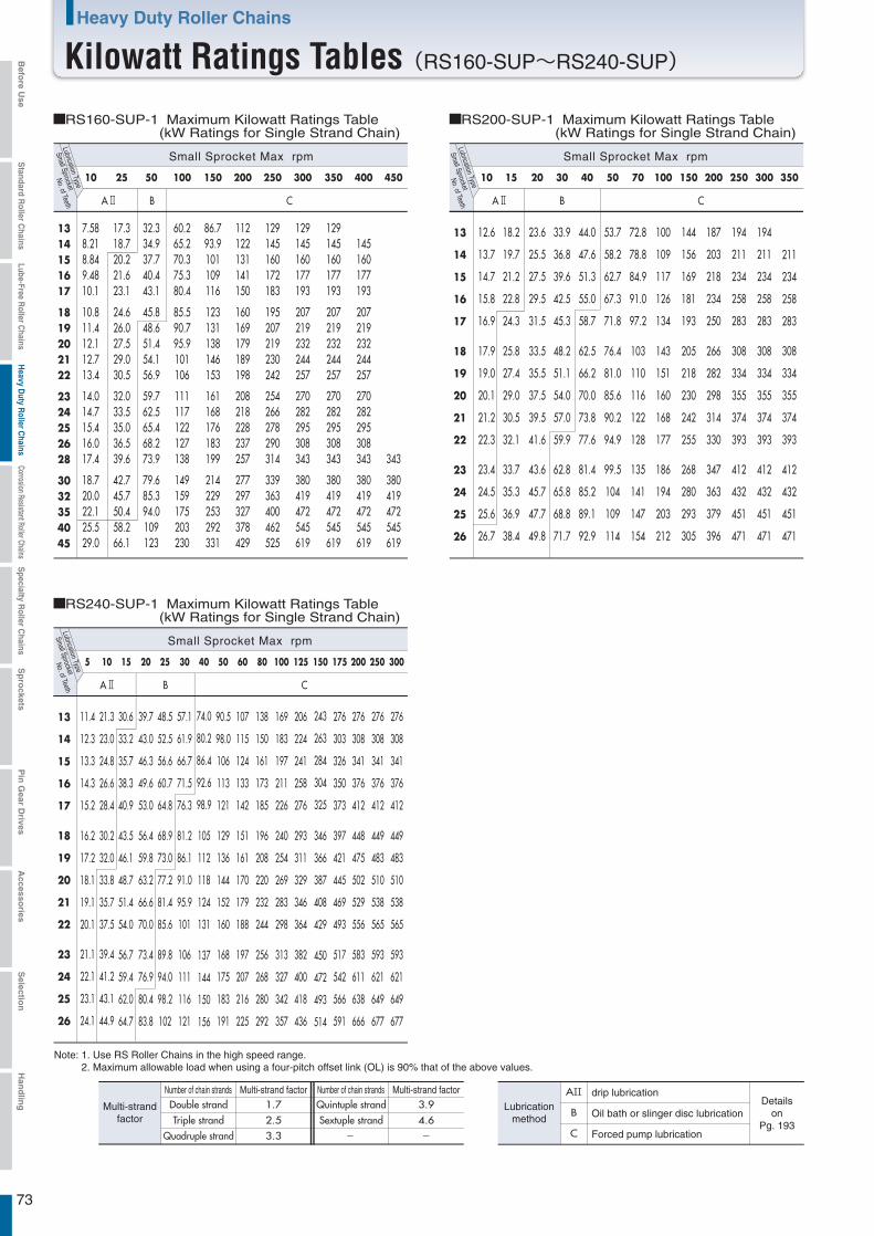
73
Heavy Duty Roller Chains
Kilowatt Ratings Tables(RS160-SUP~RS240-SUP)
CB
10 25 50 100 150 200 250 300 350 400 450
7.58 8.21 8.84 9.48 10.1
10.8 11.4 12.1 12.7 13.4
14.0 14.7 15.4 16.0 17.4
18.7 20.0 22.1 25.5 29.0
17.3 18.7 20.2 21.6 23.1
24.6 26.0 27.5 29.0 30.5
32.0 33.5 35.0 36.5 39.6
42.7 45.7 50.4 58.2 66.1
32.3 34.9 37.7 40.4 43.1
45.8 48.6 51.4 54.1 56.9
59.7 62.5 65.4 68.2 73.9
79.6 85.3 94.0 109 123
60.2 65.2 70.3 75.3 80.4
85.5 90.7 95.9 101 106
111 117 122 127 138
149 159 175 203 230
86.7 93.9 101 109 116
123 131 138 146 153
161 168 176 183 199
214 229 253 292 331
112 122 131 141 150
160 169 179 189 198
208 218 228 237 257
277 297 327 378 429
129 145 160 172 183
195 207 219 230 242
254 266 278 290 314
339 363 400 462 525
129 145 160 177 193
207 219 232 244 257
270 282 295 308 343
380 419 472 545 619
129 145 160 177 193
207 219 232 244 257
270 282 295 308 343
380 419 472 545 619
145 160 177 193
207 219 232 244 257
270 282 295 308 343
380 419 472 545 619
343
380 419 472 545 619
1314151617
1819202122
2324252628
3032354045
B C
10 15 20 30 40 50 70 100 150 200 250 300 350
B C
5 10 15 20 25 30 40 50 60 80 100 125 150 175 200 250 300
12.6
13.7
14.7
15.8
16.9
17.9
19.0
20.1
21.2
22.3
23.4
24.5
25.6
26.7
18.2
19.7
21.2
22.8
24.3
25.8
27.4
29.0
30.5
32.1
33.7
35.3
36.9
38.4
23.6
25.5
27.5
29.5
31.5
33.5
35.5
37.5
39.5
41.6
43.6
45.7
47.7
49.8
33.9
36.8
39.6
42.5
45.3
48.2
51.1
54.0
57.0
59.9
62.8
65.8
68.8
71.7
44.0
47.6
51.3
55.0
58.7
62.5
66.2
70.0
73.8
77.6
81.4
85.2
89.1
92.9
53.7
58.2
62.7
67.3
71.8
76.4
81.0
85.6
90.2
94.9
99.5
104
109
114
72.8
78.8
84.9
91.0
97.2
103
110
116
122
128
135
141
147
154
100
109
117
126
134
143
151
160
168
177
186
194
203
212
144
156
169
181
193
205
218
230
242
255
268
280
293
305
187
203
218
234
250
266
282
298
314
330
347
363
379
396
194
211
234
258
283
308
334
355
374
393
412
432
451
471
194
211
234
258
283
308
334
355
374
393
412
432
451
471
211
234
258
283
308
334
355
374
393
412
432
451
471
13
14
15
16
17
18
19
20
21
22
23
24
25
26
11.4
12.3
13.3
14.3
15.2
16.2
17.2
18.1
19.1
20.1
21.1
22.1
23.1
24.1
21.3
23.0
24.8
26.6
28.4
30.2
32.0
33.8
35.7
37.5
39.4
41.2
43.1
44.9
30.6
33.2
35.7
38.3
40.9
43.5
46.1
48.7
51.4
54.0
56.7
59.4
62.0
64.7
39.7
43.0
46.3
49.6
53.0
56.4
59.8
63.2
66.6
70.0
73.4
76.9
80.4
83.8
48.5
52.5
56.6
60.7
64.8
68.9
73.0
77.2
81.4
85.6
89.8
94.0
98.2
102
57.1
61.9
66.7
71.5
76.3
81.2
86.1
91.0
95.9
101
106
111
116
121
74.0
80.2
86.4
92.6
98.9
105
112
118
124
131
137
144
150
156
90.5
98.0
106
113
121
129
136
144
152
160
168
175
183
191
107
115
124
133
142
151
161
170
179
188
197
207
216
225
138
150
161
173
185
196
208
220
232
244
256
268
280
292
169
183
197
211
226
240
254
269
283
298
313
327
342
357
206
224
241
258
276
293
311
329
346
364
382
400
418
436
243
263
284
304
325
346
366
387
408
429
450
472
493
514
276
303
326
350
373
397
421
445
469
493
517
542
566
591
276
308
341
376
412
448
475
502
529
556
583
611
638
666
276
308
341
376
412
449
483
510
538
565
593
621
649
677
276
308
341
376
412
449
483
510
538
565
593
621
649
677
13
14
15
16
17
18
19
20
21
22
23
24
25
26
Small Sprocket
No. of TeethLubrication Type
Small Sprocket Max rpm
RS200-SUP-1 Maximum Kilowatt Ratings Table (kW Ratings for Single Strand Chain)
Small Sprocket
No. of TeethLubrication Type
Small Sprocket Max rpm
RS160-SUP-1 Maximum Kilowatt Ratings Table (kW Ratings for Single Strand Chain)
Small Sprocket
No. of TeethLubrication Type
Small Sprocket Max rpm
RS240-SUP-1 Maximum Kilowatt Ratings Table (kW Ratings for Single Strand Chain)
Number of chain strandsNumber of chain strands Multi-strand factorMulti-strand factor1.7 3.92.5 4.63.3 - -
AII
B
C
drip lubricationDetails
onPg. 193
Oil bath or slinger disc lubrication
Forced pump lubrication
Lubricationmethod
Quintuple strandSextuple strand
Double strandTriple strand
Quadruple strand
Multi-strandfactor
Note: 1. Use RS Roller Chains in the high speed range.2. Maximum allowable load when using a four-pitch offset link (OL) is 90% that of the above values.
Befo
re Use
Standard R
oller Chains
Lube-Free Roller C
hainsH
eavy Duty R
oller Chains
Corrosion Resistant Roller ChainsS
pecialty Roller C
hainsS
pro
cketsP
in G
ear Drives
Accesso
riesS
election
Han
dlin
g
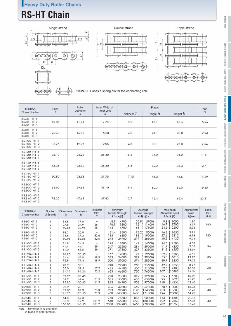
74
Heavy Duty Roller Chains
RS-HT Chain
H
P P
TWR
L2
L1
C
h
D
L2
L1
T
C
L2
L1
C
CL
12 1603
12 1203
12 963
12 803
12 683
12 603
12 483
12 403
RS60-HT-1RS60-HT-2RS60-HT-3
19.05 11.91 12.70 3.2 18.1 15.6 5.96
14.8 17.0 - 48.1{ 4900} 55.9{ 5700} 9.81{ 1000} 1.8027.8 29.9 26.1 96.1{ 9800} 112 { 11400} 16.7 { 1700} 3.5940.85 42.95 26.1 144 { 14700} 168 { 17100} 24.5 { 2500} 5.36
25.40 15.88 15.88 4.0 24.1 20.8 7.94
18.3 20.9 - 81.4{ 8300} 93.2{ 9500} 16.2 { 1650} 3.1134.6 37.2 32.6
32.6163 { 16600} 186 { 19000} 27.6 { 2810} 6.18
50.95 53.55 244 { 24900} 279 { 28500} 40.5 { 4130} 9.24
RS80-HT-1RS80-HT-2RS80-HT-3
31.75 19.05 19.05 4.8 30.1 26.0 9.54
21.8 24.5 - 124 { 12600} 142 { 14500} 24.5 { 2500} 4.5841.4 44.1 39.1
39.1247 { 25200} 284 { 29000} 41.7 { 4250} 9.03
61.0 63.6 371 { 37800} 427 { 43500} 61.3 { 6250} 13.54
RS100-HT-1RS100-HT-2RS100-HT-3
38.10 22.23 25.40 5.6 36.2 31.2 11.11
26.95 30.55 - 167 { 17000} 191 { 19500} 32.4 { 3300} 6.5351.4 55.0 48.9
48.9333 { 34000} 382 { 39000} 55.0 { 5610} 12.90
75.9 79.4 500 { 51000} 574 { 58500} 80.9 { 8250} 19.33
RS120-HT-1RS120-HT-2RS120-HT-3
44.45 25.40 25.40 6.4 42.2 36.4 12.71
28.9 33.1 - 218 { 22200} 250 { 25500} 42.7 { 4350} 8.2755.0 59.5 52.2 435 { 44400} 500 { 51000} 72.6 { 7400} 16.3881.15 85.25 653 { 66600} 750 { 76500} 107 {10880} 24.54
RS140-HT-1RS140-HT-2RS140-HT-3
50.80 28.58 31.75 7.15 48.2 41.6 14.29
33.95 38.45 - 278 { 28300} 319 { 32500} 55.9 { 5700} 10.9764.9 69.6 61.9
52.2
61.9555 { 56600} 638 { 65000} 95 { 9690} 21.78
95.95 100.45 833 { 84900} 956 { 97500} 140 {14250} 32.63
RS160-HT-1RS160-HT-2RS160-HT-3
63.50 39.68 38.10 9.5 60.3 52.0 19.85
42.9 48.1 - 486 { 49600} 559 { 57000} 78.5 { 8000} 18.4182.05 87.3 78.3 973 { 99200} 1120 {114000} 133 {13600} 36.47
121.25 126.55 1460 {148800} 1680 {171000} 196 {20000} 54.77
RS200-HT-1RS200-HT-2RS200-HT-3
76.20 47.63 47.63 12.7 72.4 62.4 23.81
54.8 62.3 - 768 { 78300} 883 { 90000} 113 {11500} 29.13105.3 112.9 101.2
78.3
101.21540 {156600} 1770 {180000} 192 {19550} 57.35
156.05 163.55 2300 {234900} 2650 {270000} 282 {28750} 85.47
RS240-HT-1RS240-HT-2RS240-HT-3
RS60-HT-1RS60-HT-2RS60-HT-3
RS80-HT-1RS80-HT-2RS80-HT-3
RS100-HT-1RS100-HT-2RS100-HT-3
RS120-HT-1RS120-HT-2RS120-HT-3
RS140-HT-1RS140-HT-2RS140-HT-3
RS160-HT-1RS160-HT-2RS160-HT-3
RS200-HT-1RS200-HT-2RS200-HT-3
RS240-HT-1RS240-HT-2RS240-HT-3
Triple strandSingle strand Double strand
PitchP
RollerDiameter
R
Inner Width ofInner Link
W
Plates PinsD
Thickness T Height H Height hTSUBAKI
Chain Number
DimensionsL1
DimensionsL2
TransversePitchC
TSUBAKIChain Number
Numberof Strands
MaximumAllowable Load
kN{kgf }
ApproximateMasskg/m
LinksPerUnit
MinimumTensile Strength
kN{kgf }
AverageTensile Strength
kN{kgf }
*RS240-HT uses a spring pin for the connecting link.
Note 1. No offset links available. 2. Made-to-order product.
Befo
re Use
Standard R
oller Chains
Lube-Free Roller C
hainsH
eavy Duty R
oller Chains
Corrosion Resistant Roller ChainsS
pecialty Roller C
hainsS
pro
cketsP
in G
ear Drives
Accesso
riesS
election
Han
dlin
g
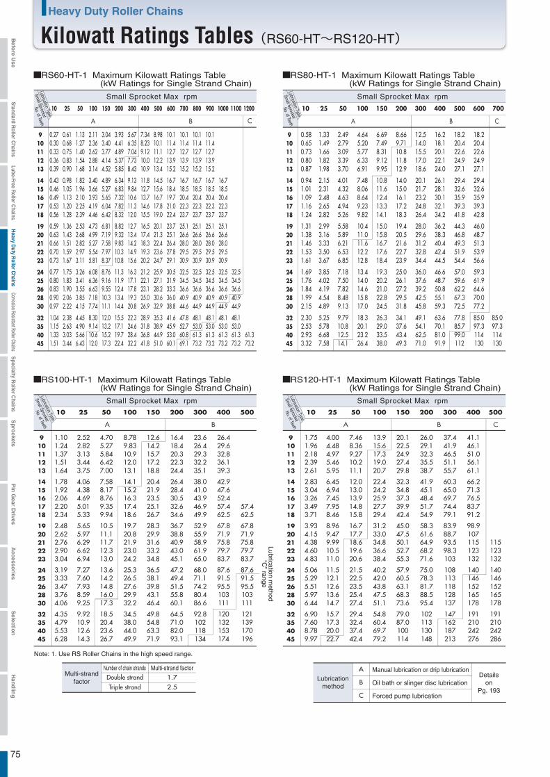
75
Heavy Duty Roller Chains
Kilowatt Ratings Tables(RS60-HT~RS120-HT)
A B C
910111213
1415161718
1920212223
2425262830
32354045
10 25 50 100 150 200 300 400 500 600 700 800 900 1000 1100 1200
0.27 0.30 0.33 0.36 0.39
0.43 0.46 0.49 0.53 0.56
0.59 0.63 0.66 0.70 0.73
0.77 0.80 0.83 0.90 0.97
1.04 1.15 1.33 1.51
0.61 0.68 0.75 0.83 0.90
0.98 1.05 1.13 1.20 1.28
1.36 1.43 1.51 1.59 1.67
1.75 1.83 1.90 2.06 2.22
2.38 2.63 3.03 3.44
1.13 1.27 1.40 1.54 1.68
1.82 1.96 2.10 2.25 2.39
2.53 2.68 2.82 2.97 3.11
3.26 3.41 3.55 3.85 4.15
4.45 4.90 5.66 6.43
2.11 2.36 2.62 2.88 3.14
3.40 3.66 3.93 4.19 4.46
4.73 4.99 5.27 5.54 5.81
6.08 6.36 6.63 7.18 7.74
8.30 9.14 10.6 12.0
3.04 3.40 3.77 4.14 4.52
4.89 5.27 5.65 6.04 6.42
6.81 7.19 7.58 7.97 8.37
8.76 9.16 9.55 10.3 11.1
12.0 13.2 15.2 17.3
3.93 4.41 4.89 5.37 5.85
6.34 6.83 7.32 7.82 8.32
8.82 9.32 9.83 10.3 10.8
11.3 11.9 12.4 13.4 14.4
15.5 17.1 19.7 22.4
5.67 6.35 7.04 7.73 8.43
9.13 9.84 10.6 11.3 12.0
12.7 13.4 14.2 14.9 15.6
16.3 17.1 17.8 19.3 20.8
22.3 24.6 28.4 32.2
7.34 8.23 9.12 10.0 10.9
11.8 12.7 13.7 14.6 15.5
16.5 17.4 18.3 19.3 20.2
21.2 22.1 23.1 25.0 26.9
28.9 31.8 36.8 41.8
8.98 10.1 11.1 12.2 13.4
14.5 15.6 16.7 17.8 19.0
20.1 21.3 22.4 23.6 24.7
25.9 27.1 28.2 30.6 32.9
35.3 38.9 44.9 51.0
10.1 11.4 12.7 13.9 15.2
16.7 18.4 19.7 21.0 22.4
23.7 25.1 26.4 27.8 29.1
30.5 31.9 33.3 36.0 38.8
41.6 45.9 53.0 60.1
10.1 11.4 12.7 13.9 15.2
16.7 18.5 20.4 22.3 23.7
25.1 26.6 28.0 29.5 30.9
32.5 34.5 36.6 40.9 44.6
47.8 52.7 60.8 69.1
10.1 11.4 12.7 13.9 15.2
16.7 18.5 20.4 22.3 23.7
25.1 26.6 28.0 29.5 30.9
32.5 34.5 36.6 40.9 44.9
48.1 53.0 61.3 73.2
10.1 11.4 12.7 13.9 15.2
16.7 18.5 20.4 22.3 23.7
25.1 26.6 28.0 29.5 30.9
32.5 34.5 36.6 40.9 44.9
48.1 53.0 61.3 73.2
16.7 18.5 20.4 22.3 23.7
25.1 26.6 28.0 29.5 30.9
32.5 34.5 36.6 40.9 44.9
48.1 53.0 61.3 73.2
32.5 34.5 36.6 40.9 44.9
48.1 53.0 61.3 73.2
61.3 73.2
A B C
910111213
1415161718
1920212223
2425262830
32354045
10 25 50 100 150 200 300 400 500 600 700
0.58 0.65 0.73 0.80 0.87
0.94 1.01 1.09 1.16 1.24
1.31 1.38 1.46 1.53 1.61
1.69 1.76 1.84 1.99 2.15
2.30 2.53 2.93 3.32
1.33 1.49 1.66 1.82 1.98
2.15 2.31 2.48 2.65 2.82
2.99 3.16 3.33 3.50 3.67
3.85 4.02 4.19 4.54 4.89
5.25 5.78 6.68 7.58
2.49 2.79 3.09 3.39 3.70
4.01 4.32 4.63 4.94 5.26
5.58 5.89 6.21 6.53 6.85
7.18 7.50 7.82 8.48 9.13
9.79 10.8 12.5 14.1
4.64 5.20 5.77 6.33 6.91
7.48 8.06 8.64 9.23 9.82
10.4 11.0 11.6 12.2 12.8
13.4 14.0 14.6 15.8 17.0
18.3 20.1 23.2 26.4
6.69 7.49 8.31 9.12 9.95
10.8 11.6 12.4 13.3 14.1
15.0 15.8 16.7 17.6 18.4
19.3 20.2 21.0 22.8 24.5
26.3 29.0 33.5 38.0
8.66 9.71 10.8 11.8 12.9
14.0 15.0 16.1 17.2 18.3
19.4 20.5 21.6 22.7 23.9
25.0 26.1 27.2 29.5 31.8
34.1 37.6 43.4 49.3
12.5 14.0 15.5 17.0 18.6
20.1 21.7 23.2 24.8 26.4
28.0 29.6 31.2 32.8 34.4
36.0 37.6 39.2 42.5 45.8
49.1 54.1 62.5 71.0
16.2 18.1 20.1 22.1 24.0
26.1 28.1 30.1 32.1 34.2
36.2 38.3 40.4 42.4 44.5
46.6 48.7 50.8 55.1 59.3
63.6 70.1 81.0 91.9
18.2 20.4 22.6 24.9 27.1
29.4 32.6 35.9 39.3 41.8
44.3 46.8 49.3 51.9 54.4
57.0 59.6 62.2 67.3 72.5
77.8 85.7 99.0 112
18.2 20.4 22.6 24.9 27.1
29.4 32.6 35.9 39.3 42.8
46.0 48.7 51.3 53.9 56.6
59.3 61.9 64.6 70.0 77.2
85.0 97.3 114 130
85.0 97.3 114 130
A B
910111213
1415161718
1920212223
2425262830
32354045
10 25 50 100 150 200 300 400 500
1.10 1.24 1.37 1.51 1.64
1.78 1.92 2.06 2.20 2.34
2.48 2.62 2.76 2.90 3.04
3.19 3.33 3.47 3.76 4.06
4.35 4.79 5.53 6.28
2.52 2.82 3.13 3.44 3.75
4.06 4.38 4.69 5.01 5.33
5.65 5.97 6.29 6.62 6.94
7.27 7.60 7.93 8.59 9.25
9.92 10.9 12.6 14.3
4.70 5.27 5.84 6.42 7.00
7.58 8.17 8.76 9.35 9.94
10.5 11.1 11.7 12.3 13.0
13.6 14.2 14.8 16.0 17.3
18.5 20.4 23.6 26.7
8.78 9.83 10.9 12.0 13.1
14.1 15.2 16.3 17.4 18.6
19.7 20.8 21.9 23.0 24.2
25.3 26.5 27.6 29.9 32.2
34.5 38.0 44.0 49.9
12.6 14.2 15.7 17.2 18.8
20.4 21.9 23.5 25.1 26.7
28.3 29.9 31.6 33.2 34.8
36.5 38.1 39.8 43.1 46.4
49.8 54.8 63.3 71.9
16.4 18.4 20.3 22.3 24.4
26.4 28.4 30.5 32.6 34.6
36.7 38.8 40.9 43.0 45.1
47.2 49.4 51.5 55.8 60.1
64.5 71.0 82.0 93.1
23.6 26.4 29.3 32.2 35.1
38.0 41.0 43.9 46.9 49.9
52.9 55.9 58.9 61.9 65.0
68.0 71.1 74.2 80.4 86.6
92.8 102 118 134
26.4 29.6 32.8 36.1 39.3
42.9 47.6 52.4 57.4 62.5
67.8 71.9 75.8 79.7 83.7
87.6 91.5 95.5 103 111
120 132 153 174
57.4 62.5
67.8 71.9 75.8 79.7 83.7
87.6 91.5 95.5 103 111
121 139 170 196
A B C
910111213
1415161718
1920212223
2425262830
32354045
10 25 50 100 150 200 300 400 500
1.75 1.96 2.18 2.39 2.61
2.83 3.04 3.26 3.49 3.71
3.93 4.15 4.38 4.60 4.83
5.06 5.29 5.51 5.97 6.44
6.90 7.60 8.78 9.97
4.00 4.48 4.97 5.46 5.95
6.45 6.94 7.45 7.95 8.46
8.96 9.47 9.99 10.5 11.0
11.5 12.1 12.6 13.6 14.7
15.7 17.3 20.0 22.7
7.46 8.36 9.27 10.2 11.1
12.0 13.0 13.9 14.8 15.8
16.7 17.7 18.6 19.6 20.6
21.5 22.5 23.5 25.4 27.4
29.4 32.4 37.4 42.4
13.9 15.6 17.3 19.0 20.7
22.4 24.2 25.9 27.7 29.4
31.2 33.0 34.8 36.6 38.4
40.2 42.0 43.8 47.5 51.1
54.8 60.4 69.7 79.2
20.1 22.5 24.9 27.4 29.8
32.3 34.8 37.3 39.9 42.4
45.0 47.5 50.1 52.7 55.3
57.9 60.5 63.1 68.3 73.6
79.0 87.0 100 114
26.0 29.1 32.3 35.5 38.7
41.9 45.1 48.4 51.7 54.9
58.3 61.6 64.9 68.2 71.6
75.0 78.3 81.7 88.5 95.4
102 113 130 148
37.4 41.9 46.5 51.1 55.7
60.3 65.0 69.7 74.4 79.1
83.9 88.7 93.5 98.3 103
108 113 118 128 137
147 162 187 213
41.1 46.1 51.0 56.1 61.1
66.2 71.3 76.5 83.7 91.2
98.9 107 115 123 132
140 146 152 165 178
191 210 242 276
115 123 132
140 146 152 165 178
191 210 242 286
Small Sprocket
No. of TeethLubrication Type
Small Sprocket Max rpm
RS80-HT-1 Maximum Kilowatt Ratings Table (kW Ratings for Single Strand Chain)
Small Sprocket
No. of TeethLubrication Type
Small Sprocket Max rpm
RS60-HT-1 Maximum Kilowatt Ratings Table (kW Ratings for Single Strand Chain)
Small Sprocket
No. of TeethLubrication Type
Small Sprocket Max rpm
RS100-HT-1 Maximum Kilowatt Ratings Table (kW Ratings for Single Strand Chain)
Small Sprocket
No. of TeethLubrication Type
Small Sprocket Max rpm
RS120-HT-1 Maximum Kilowatt Ratings Table (kW Ratings for Single Strand Chain)
Number of chain strands Multi-strand factor1.72.5
A
B
C
Manual lubrication or drip lubricationDetails
onPg. 193
Oil bath or slinger disc lubrication
Forced pump lubrication
Lubricationmethod
Double strandTriple strand
Multi-strandfactor
Note: 1. Use RS Roller Chains in the high speed range.
Lubrication method
“C” range
Befo
re Use
Standard R
oller Chains
Lube-Free Roller C
hainsH
eavy Duty R
oller Chains
Corrosion Resistant Roller ChainsS
pecialty Roller C
hainsS
pro
cketsP
in G
ear Drives
Accesso
riesS
election
Han
dlin
g
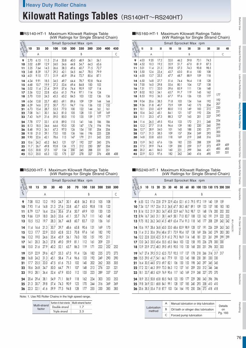
76
Heavy Duty Roller Chains
Kilowatt Ratings Tables(RS140HT~RS240HT)
A B C
910111213
1415161718
1920212223
2425262830
32354045
10 25 50 100 150 200 250 300 350 400 450
2.70 3.02 3.35 3.68 4.01
4.34 4.68 5.02 5.36 5.70
6.04 6.39 6.73 7.08 7.43
7.78 8.13 8.48 9.18 9.90
10.6 11.7 13.5 15.3
6.15 6.89 7.64 8.39 9.15
9.91 10.7 11.4 12.2 13.0
13.8 14.6 15.4 16.1 16.9
17.7 18.5 19.3 21.0 22.6
24.2 26.7 30.8 35.0
11.5 12.9 14.3 15.7 17.1
18.5 19.9 21.4 22.8 24.3
25.7 27.2 28.7 30.1 31.6
33.1 34.6 36.1 39.1 42.1
45.2 49.8 57.5 65.3
21.4 24.0 26.6 29.2 31.9
34.5 37.2 39.9 42.6 45.3
48.0 50.7 53.5 56.2 59.0
61.8 64.6 67.3 73.0 78.6
84.3 92.8 107 122
30.8 34.6 38.3 42.1 45.9
49.7 53.6 57.4 61.3 65.2
69.1 73.1 77.0 81.0 85.0
89.0 93.0 97.0 105 113
121 134 154 175
40.0 44.8 49.6 54.5 59.4
64.4 69.4 74.4 79.4 84.5
89.6 94.7 100 105 110
115 120 126 136 147
157 173 200 227
48.9 54.7 60.7 66.7 72.7
78.7 84.8 90.9 97.1 103
109 116 122 128 135
141 147 154 166 179
192 212 245 278
56.1 64.5 71.5 78.5 85.6
92.8 100 107 114 122
129 136 144 151 159
166 174 181 196 211
227 250 288 327
56.1 65.6 72.7 79.9 87.1
94.4 103 114 124 136
144 152 161 169 177
186 194 204 225 243
260 287 331 376
136
144 152 161 169 177
186 194 204 228 253
276 304 351 408 408
A B C
910111213
1415161718
1920212223
2425262830
32354045
10 25 50 100 150 200 250 300 350 400
4.03 4.52 5.01 5.50 6.00
6.50 7.00 7.51 8.02 8.53
9.04 9.56 10.1 10.6 11.1
11.6 12.2 12.7 13.7 14.8
15.9 17.5 20.2 22.9
9.20 10.3 11.4 12.6 13.7
14.8 16.0 17.1 18.3 19.5
20.6 21.8 23.0 24.2 25.3
26.5 27.7 28.9 31.3 33.8
36.2 39.9 46.1 52.3
17.2 19.2 21.3 23.4 25.5
27.7 29.8 32.0 34.1 36.3
38.5 40.7 42.9 45.1 47.3
49.5 51.8 54.0 58.5 63.0
67.6 74.4 86.0 97.6
32.0 35.9 39.8 43.7 47.7
51.6 55.6 59.6 63.7 67.7
71.8 75.9 80.0 84.1 88.3
92.4 96.6 101 109 118
126 139 160 182
46.2 51.7 57.3 63.0 68.7
74.4 80.1 85.9 91.7 97.6
103 109 115 121 127
133 139 145 157 169
182 200 231 262
59.8 67.0 74.3 81.6 88.9
96.4 104 111 119 126
134 142 149 157 165
172 180 188 204 219
235 259 299 340
73.1 81.9 90.8 100 109
118 127 136 145 155
164 173 183 192 201
211 220 230 249 268
288 317 366 416
74.5 87.3 98.5 108 118
128 138 148 162 177
192 204 215 226 237
248 260 271 293 316
339 373 431 490
177
192 207 220 231 243
254 266 277 300 325
358 409 485 551
409 485 551
A B C
910111213
1415161718
1920212223
242526
10 15 20 30 40 50 70 100 150 200 300
7.08 7.93 8.79 9.66 10.5
11.4 12.3 13.2 14.1 15.0
15.9 16.8 17.7 18.6 19.5
20.4 21.3 22.3
10.2 11.4 12.7 13.9 15.2
16.4 17.7 19.0 20.3 21.6
22.9 24.2 25.5 26.8 28.1
29.4 30.7 32.1
13.2 14.8 16.4 18.0 19.7
21.3 22.9 24.6 26.3 27.9
29.6 31.3 33.0 34.7 36.4
38.1 39.8 41.6
19.0 21.3 23.6 26.0 28.3
30.7 33.0 35.4 37.8 40.2
42.7 45.1 47.5 50.0 52.4
54.9 57.4 59.9
24.7 27.6 30.6 33.6 36.7
39.7 42.8 45.9 49.0 52.1
55.3 58.4 61.6 64.7 67.9
71.1 74.3 77.5
30.1 33.8 37.4 41.1 44.8
48.6 52.3 56.1 59.9 63.7
67.5 71.4 75.3 79.1 83.0
86.9 90.9 94.8
40.8 45.7 50.7 55.7 60.7
65.8 70.8 76.0 81.1 86.3
91.4 96.6 102 107 112
118 123 128
56.2 63.0 69.9 76.7 83.7
90.6 97.6 105 112 119
126 133 140 148 155
162 170 177
81.0 90.8 101 111 121
131 141 151 161 171
182 192 202 213 223
234 244 255
105 118 130 143 156
169 182 195 209 222
235 249 262 276 289
303 316 330
252
273 290 305 321 337
353 369 385
250
108 122 135 148 161
175 192 211 231 252
273 290 305 321 337
353 369 385
A B
910111213
1415161718
1920212223
242526
5 10 15 20 25 30 40 50 60 80 100 125 150 175 200 250
6.55 7.34 8.14 8.94 9.75
10.6 11.4 12.2 13.0 13.9
14.7 15.5 16.4 17.2 18.1
18.9 19.8 20.6
12.2 13.7 15.2 16.7 18.2
19.7 21.2 22.8 24.3 25.9
27.4 29.0 30.5 32.1 33.7
35.3 36.9 38.5
17.6 19.7 21.9 24.0 26.2
28.4 30.6 32.8 35.0 37.2
39.5 41.7 44.0 46.3 48.5
50.8 53.1 55.4
22.8 25.6 28.3 31.1 34.0
36.8 39.6 42.5 45.4 48.3
51.2 54.1 57.0 59.9 62.9
65.8 68.8 71.8
27.9 31.3 34.7 38.1 41.5
45.0 48.4 51.9 55.5 59.0
62.5 66.1 69.7 73.3 76.9
80.5 84.1 87.7
32.9 36.8 40.8 44.9 48.9
53.0 57.1 61.2 65.3 69.5
73.7 77.9 82.1 86.3 90.6
94.8 99.1 103
42.6 47.7 52.9 58.1 63.4
68.6 73.9 79.3 84.6 90.0
95.5 101 106 112 117
123 128 134
52.1 58.3 64.7 71.0 77.4
83.9 90.4 96.9 103 110
117 123 130 137 143
150 157 164
61.3 68.7 76.2 83.7 91.3
98.9 107 114 122 130
137 145 153 161 169
177 185 193
79.5 89.1 98.7 108 118
128 138 148 158 168
178 188 198 209 219
229 240 250
97.2 109 121 133 145
157 169 181 193 205
218 230 243 255 268
280 293 306
119 133 148 162 177
191 206 221 236 251
266 281 297 312 327
343 358 373
140 157 174 191 208
226 243 261 278 296
314 330 345 346 370
396 410 418
159 180 200 219 239
259 279 299 300 303
317 330 345 346 370
396 410 418
159 183 202 222 242
263 283 299 300 303
317
183 202 222 242
263 283 299
※C区分
Small Sprocket
No. of TeethLubrication Type
Small Sprocket Max rpm
RS160-HT-1 Maximum Kilowatt Ratings Table (kW Ratings for Single Strand Chain)
Small Sprocket
No. of TeethLubrication Type
Small Sprocket Max rpm
RS140-HT-1 Maximum Kilowatt Ratings Table (kW Ratings for Single Strand Chain)
Small Sprocket
No. of TeethLubrication Type
Small Sprocket Max rpm
RS200-HT-1 Maximum Kilowatt Ratings Table (kW Ratings for Single Strand Chain)
Small Sprocket
No. of TeethLubrication Type
Small Sprocket Max rpm
RS240-HT-1 Maximum Kilowatt Ratings Table (kW Ratings for Single Strand Chain)
Number of chain strands Multi-strand factor1.72.5
A
B
C
Manual lubrication or drip lubricationDetails
onPg. 193
Oil bath or slinger disc lubrication
Forced pump lubrication
Lubricationmethod
Double strandTriple strand
Multi-strandfactor
Note: 1. Use RS Roller Chains in the high speed range.
Befo
re Use
Standard R
oller Chains
Lube-Free Roller C
hainsH
eavy Duty R
oller Chains
Corrosion Resistant Roller ChainsS
pecialty Roller C
hainsS
pro
cketsP
in G
ear Drives
Accesso
riesS
election
Han
dlin
g
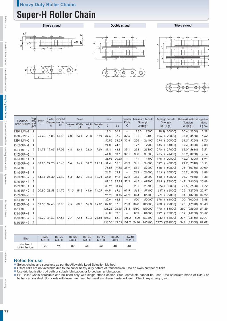
Single strand Double strand Triple strand
120 96 80 68 60 48 40
RS80-SUP-H-1 1
25.40 15.88 15.88 4.0 24.1 20.8 7.94
18.3 20.9 - 85.3{ 8700} 98.1{ 10000} 20.6{ 2100} 3.29
RS80-SUP-H-2 2 34.6 37.2 32.6 171 { 17400} 196 { 20000} 35.0{ 3570} 6.52
RS80-SUP-H-3 3 50.95 53.55 32.6 256 { 26100} 294 { 30000} 51.5{ 5250} 9.75
RS100-SUP-H-1
RS100-SUP-H-2
RS100-SUP-H-3RS120-SUP-H-1
RS120-SUP-H-2
RS120-SUP-H-3
RS140-SUP-H-1
RS140-SUP-H-2
RS140-SUP-H-3RS160-SUP-H-1
RS160-SUP-H-2
RS160-SUP-H-3
RS200-SUP-H-1
RS200-SUP-H-2
RS200-SUP-H-3
RS240-SUP-H-1
RS240-SUP-H-2
RS240-SUP-H-3
1
31.75 19.05 19.05 4.8 30.1 26.0 9.54
21.8 24.5 - 127 { 12900} 145 { 14800} 32.4{ 3300} 4.88
2 41.4 44.1 39.1 253 { 25800} 290 { 29600} 55.0{ 5610} 9.51
3 61.0 63.6 39.1 380 { 38700} 435 { 44400} 80.9{ 8250} 14.14
1
38.10 22.23 25.40 5.6 36.2 31.2 11.11
26.95 30.55 - 171 { 17400} 196 { 20000} 42.2{ 4300} 6.94
2 51.4 55.0 48.9 341 { 34800} 392 { 40000} 71.7{ 7310} 13.51
3 75.85 79.55 48.9 512 { 52200} 588 { 60000} 105 {10750} 20.09
1
44.45 25.40 25.40 6.4 42.2 36.4 12.71
28.9 33.1 - 222 { 22600} 255 { 26000} 56.9{ 5800} 8.88
2 55.0 59.5 52.2 443 { 45200} 510 { 52000} 96.7{ 9860} 17.38
3 81.15 85.25 52.2 665 { 67800} 765 { 78000} 142 {14500} 25.88
1
50.80 28.58 31.75 7.15 48.2 41.6 14.29
33.95 38.45 - 281 { 28700} 324 { 33000} 73.5{ 7500} 11.72
2 64.9 69.6 61.9 563 { 57400} 647 { 66000} 125 {12750} 22.97
3 95.95 100.45 61.9 844 { 86100} 971 { 99000} 184 {18750} 34.22
1
63.50 39.68 38.10 9.5 60.3 52.0 19.85
42.9 48.1 - 520 { 53000} 598 { 61000} 100 {10200} 19.68
2 82.05 87.3 78.3 1040 {106000} 1200 {122000} 170 {17340} 38.48
3 121.25 126.55 78.3 1560 {159000} 1790 {183000} 250 {25500} 57.29
1
76.20 47.63 47.63 12.7 72.4 62.4 23.81
54.8 62.3 - 802 { 81800} 922 { 94000} 139 {14200} 30.47
2 105.3 112.9 101.2 1600 {163600} 1840 {188000} 237 {24140} 59.77
3 156.05 163.55 101.2 2410 {245400} 2770 {282000} 348 {35500} 89.09
RS80SUP-H
RS100SUP-H
RS120SUP-H
RS140SUP-H
RS160SUP-H
RS200SUP-H
RS240SUP-H
WT
PP
D R
L2
L1
L2
L1
C
L2
L1
CC
Th H
kN{kg f } kN{kg f } kN{kg f } kg/m
TSUBAKIChain Number
Num
berof S
trands
PitchP
RollerDiameter
R
Inner Width ofInner Link
W
Plates
ThicknessT
WidthH
Widthh
Pins
DiameterD L 1 L 2
TransversePitch
C
Minimum TensileStrength
Maximum Allowable LoadTension
Average TensileStrength
ApproximateMass
Number ofLinks Per Unit
Size
Notes for useSelect chains and sprockets as per the Allowable Load Selection Method.Offset links are not available due to the super heavy duty nature of transmission. Use an even number of links.Use drip lubrication, oil bath or splash lubrication, or forced pump lubrication.RS Roller Chain sprockets can be used only with single strand chains. Steel sprockets cannot be used. Use sprockets made of S35C or higher carbon steel. Sprockets with lower teeth number must also have hardened teeth. Check key strength, etc.
77
Heavy Duty Roller Chains
Super-H Roller ChainBefo
re Use
Standard R
oller Chains
Lube-Free Roller C
hainsH
eavy Duty R
oller Chains
Corrosion Resistant Roller ChainsS
pecialty Roller C
hainsS
pro
cketsP
in G
ear Drives
Accesso
riesS
election
Han
dlin
g
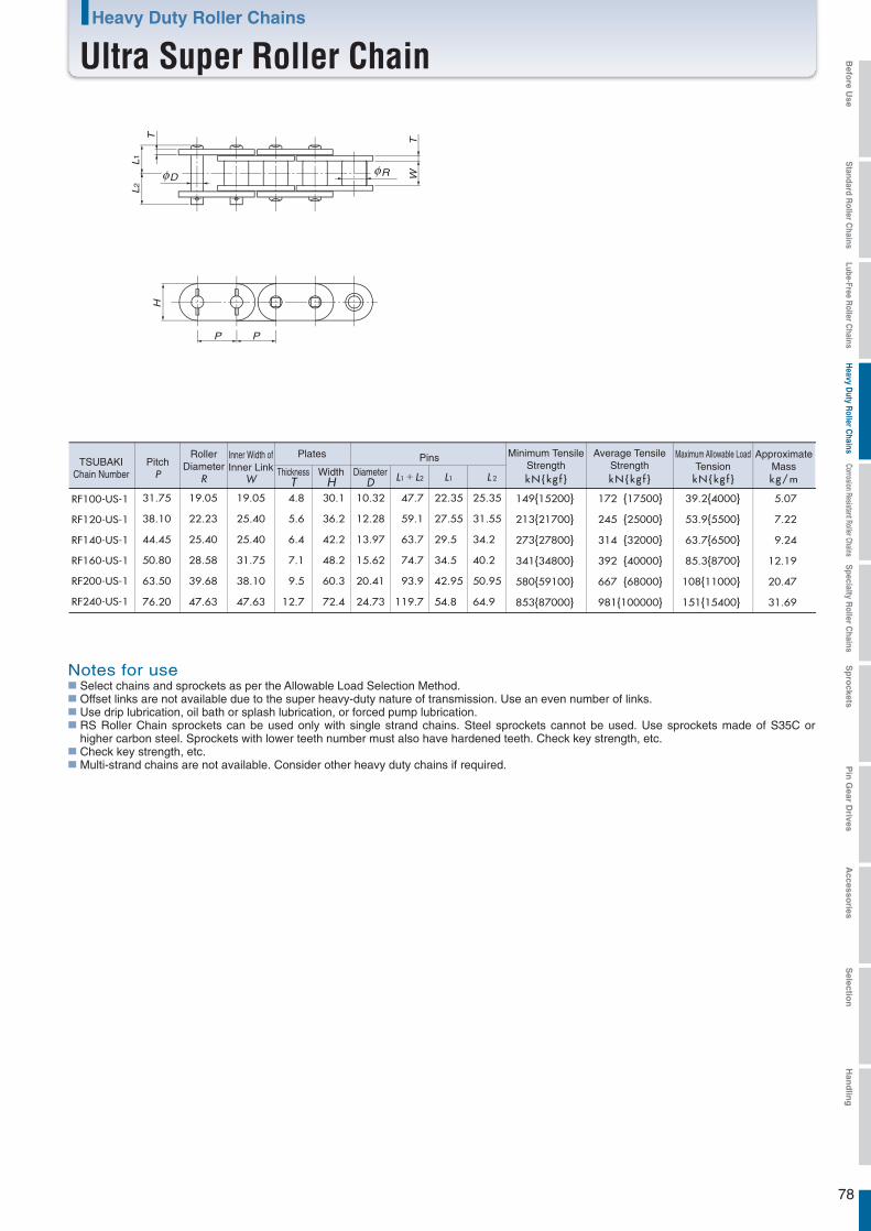
RF100-US-1
RF120-US-1
RF140-US-1
RF160-US-1
RF200-US-1
RF240-US-1
31.75 19.05 19.05 4.8 30.1 10.32 47.7 22.35 25.35
38.10 22.23 25.40 5.6 36.2 12.28 59.1 27.55 31.55
44.45 25.40 25.40 6.4 42.2 13.97 63.7 29.5 34.2
50.80 28.58 31.75 7.1 48.2 15.62 74.7 34.5 40.2
63.50 39.68 38.10 9.5 60.3 20.41 93.9 42.95 50.95
76.20 47.63 47.63 12.7 72.4 24.73 119.7 54.8 64.9
149{15200} 172 {17500} 39.2{4000} 5.07
213{21700} 245 {25000} 53.9{5500} 7.22
273{27800} 314 {32000} 63.7{6500} 9.24
341{34800} 392 {40000} 85.3{8700} 12.19
580{59100} 667 {68000} 108{11000} 20.47
853{87000} 981{100000} 151{15400} 31.69
WT
PP
D R
L1
L2
TH
TSUBAKIChain Number
PitchP
RollerDiameter
R
Inner Width ofInner Link
W
Plates PinsDiameter
DThickness
TWidth
H L1+L2 L1 L 2 kN{kg f }
Minimum TensileStrength
kN{kg f }
Maximum Allowable LoadTension
kN{kg f }
Average TensileStrength
kg/m
ApproximateMass
Notes for useSelect chains and sprockets as per the Allowable Load Selection Method.Offset links are not available due to the super heavy-duty nature of transmission. Use an even number of links.Use drip lubrication, oil bath or splash lubrication, or forced pump lubrication.RS Roller Chain sprockets can be used only with single strand chains. Steel sprockets cannot be used. Use sprockets made of S35C or higher carbon steel. Sprockets with lower teeth number must also have hardened teeth. Check key strength, etc.Check key strength, etc.Multi-strand chains are not available. Consider other heavy duty chains if required.
Heavy Duty Roller Chains
Ultra Super Roller Chain
78
Befo
re Use
Standard R
oller Chains
Lube-Free Roller C
hainsH
eavy Duty R
oller Chains
Corrosion Resistant Roller ChainsS
pecialty Roller C
hainsS
pro
cketsP
in G
ear Drives
Accesso
riesS
election
Han
dlin
g
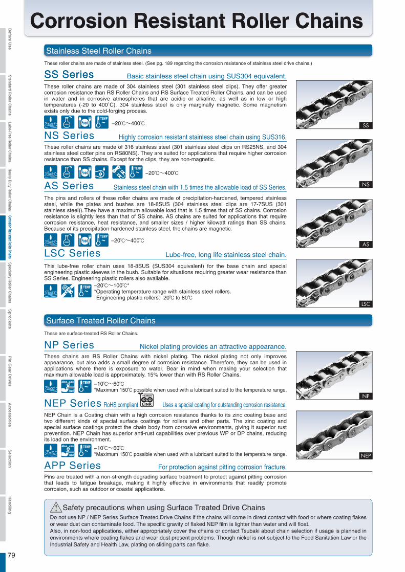
Pins are treated with a non-strength degrading surface treatment to protect against pitting corrosion that leads to fatigue breakage, making it highly effective in environments that readily promote corrosion, such as outdoor or coastal applications.
APP Series
! Safety precautions when using Surface Treated Drive ChainsDo not use NP / NEP Series Surface Treated Drive Chains if the chains will come in direct contact with food or where coating flakes or wear dust can contaminate food. The specific gravity of flaked NEP film is lighter than water and will float. Also, in non-food applications, either appropriately cover the chains or contact Tsubaki about chain selection if usage is planned in environments where coating flakes and wear dust present problems. Though nickel is not subject to the Food Sanitation Law or the Industrial Safety and Health Law, plating on sliding parts can flake.
These roller chains are made of 304 stainless steel (301 stainless steel clips). They offer greater corrosion resistance than RS Roller Chains and RS Surface Treated Roller Chains, and can be used in water and in corrosive atmospheres that are acidic or alkaline, as well as in low or high temperatures (-20 to 400˚C). 304 stainless steel is only marginally magnetic. Some magnetism exists only due to the cold-forging process.
SS Series
Corrosion Resistant Roller Chains
79
Stainless Steel Roller Chains
Surface Treated Roller ChainsThese are surface-treated RS Roller Chains.
These roller chains are made of stainless steel. (See pg. 189 regarding the corrosion resistance of stainless steel drive chains.)
Basic stainless steel chain using SUS304 equivalent.
For protection against pitting corrosion fracture.
−20℃~400℃
These roller chains are made of 316 stainless steel (301 stainless steel clips on RS25NS, and 304 stainless steel cotter pins on RS80NS). They are suited for applications that require higher corrosion resistance than SS chains. Except for the clips, they are non-magnetic.
NS Series Highly corrosion resistant stainless steel chain using SUS316.
−20℃~400℃
AS Series
LSC Series
The pins and rollers of these roller chains are made of precipitation-hardened, tempered stainless steel, while the plates and bushes are 18-8SUS (304 stainless steel clips are 17-7SUS (301 stainless steel)). They have a maximum allowable load that is 1.5 times that of SS chains. Corrosion resistance is slightly less than that of SS chains. AS chains are suited for applications that require corrosion resistance, heat resistance, and smaller sizes / higher kilowatt ratings than SS chains. Because of its precipitation-hardened stainless steel, the chains are magnetic.
Stainless steel chain with 1.5 times the allowable load of SS Series.
−20℃~400℃
Lube-free, long life stainless steel chain.
−20℃~100℃**Operating temperature range with stainless steel rollers. Engineering plastic rollers: -20℃ to 80℃
NP SeriesThese chains are RS Roller Chains with nickel plating. The nickel plating not only improves appearance, but also adds a small degree of corrosion resistance. Therefore, they can be used in applications where there is exposure to water. Bear in mind when making your selection that maximum allowable load is approximately. 15% lower than with RS Roller Chains.
Nickel plating provides an attractive appearance.
−10℃~60℃*Maximum 150℃ possible when used with a lubricant suited to the temperature range.
NEP SeriesNEP Chain is a Coating chain with a high corrosion resistance thanks to its zinc coating base and two different kinds of special surface coatings for rollers and other parts. The zinc coating and special surface coatings protect the chain body from corrosive environments, giving it superior rust prevention. NEP Chain has superior anti-rust capabilities over previous WP or DP chains, reducing its load on the environment.
Uses a special coating for outstanding corrosion resistance.
−10℃~60℃*Maximum 150℃ possible when used with a lubricant suited to the temperature range.
RoHS compliant
This lube-free roller chain uses 18-8SUS (SUS304 equivalent) for the base chain and special engineering plastic sleeves in the bush. Suitable for situations requiring greater wear resistance than SS Series. Engineering plastic rollers also available.
Befo
re Use
Standard R
oller Chains
Lube-Free Roller C
hainsH
eavy Duty R
oller Chains
Corrosion Resistant Roller ChainsS
pecialty Roller C
hainsS
pro
cketsP
in G
ear Drives
Accesso
riesS
election
Han
dlin
g

Poly Steel Chain that conforms to BS standards.BS-PC (BS Standard Series)
! Pre-Delivery Lubrication●
●
SS Series and NS Series Stainless Steel Roller Chains, Titanium Roller Chains, and Curved Stainless Steel Roller Chains are not lubricated before delivery. Always lubricate your chain before use, except when chains are to be used submerged in or in contact with water. If chains are not lubricated for use, then they may suffer articulation problems prematurely.The maximum allowable load is calculated under lubricated conditions (including water lubricant).
*RS11-SS-1 chain is lubricated.
Poly Steel® Chains
The pins and outer plates of these chains are made of titanium, while the inner plates are of a special engineered plastic (matte white); therefore they are suited for applications in which PC Chains have insufficient corrosion resistance. They can be used in temperatures of –20 to 80˚C. For details on corrosion resistance selection, see pg. 188. Bear in mind when making your selection that maximum allowable load is about 60% that of PC Chains.
PC-SY (Super Chemical Resistance Series)
The pins and outer plates of these chains are made of 304 stainless steel (301 stainless steel clips), while the inner plates are of engineered plastic (white). They are lube-free, low noise (5 dB less than RS Roller Chains) and lightweight (50% of RS Roller Chains). They can be used in temperatures of –20 to 80˚C. For details on corrosion resistance selection, see pg. 188.
PC (Standard Series)
These chains emit 6 to 8 dB less noise than pre-lubed RS Roller Chains (in-house comparison testing).
Low Noise Roller Chains
These roller chains have a wide sideflex due to its original pin / bush construction and the large clearance between its plates. Curved transmission is easy using RS-type standard sprockets.
Curved Stainless Steel Roller Chains
Titanium chains are non-magnetic and offer high corrosion resistance. For details on corrosion resistance selection, see pg. 188.
Titanium Roller Chains
These chains can be used in lower temperatures than RS Roller Chains yet deliver the same allowable load (when using an F-type connecting link). Expect a 20% reduction in strength when using an M-type connecting link.
Cold Resistant Roller Chains
80
KeyChemical resistantResistant to various chemicals. (Consult Tsubaki’s chemical resistance chart for more details.)
Allowable loadHas an allowable load similar to steel chains (80% to 100%)
Lube-freeRequires no additional lubrication
Non-magneticNo magnetism.
Corrosion resistantUsable in contact with water
Resistant to stress corrosion crackingResistant to hydrogen embrittlement fracture.
Low noiseRuns quieter than standard roller chain.
WeightRelatively lightweight and easy to handle.
Operating temperature rangeTemperature range for chain operation.
SanitaryRelatively hygienic to use.
Clean, quiet running chain.
Poly Steel Chain with superb chemical resistance.
-6~~-8dB
-5dB
−20℃~400℃
−10℃~60℃
−20℃~80℃
−20℃~80℃
−20℃~400℃
−40℃~60℃**Can be used at -60ºC when selected by temperature.
Befo
re Use
Standard R
oller Chains
Lube-Free Roller C
hainsH
eavy Duty R
oller Chains
Corrosion Resistant Roller ChainsS
pecialty Roller C
hainsS
pro
cketsP
in G
ear Drives
Accesso
riesS
election
Han
dlin
g
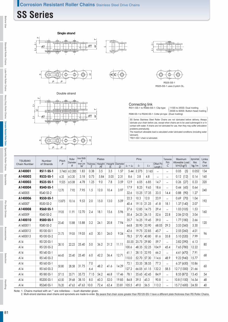
RS25-SS-1
RS25-SS-1 uses 2-pitch OL.
h
P P
L1
L2
L
T
TW
H
L1
L2
TC
h
P P
H
TW
L1
L1
D R
D R
Single strand
Double strand
Connecting linkRS11-SS-1 to RS60-SS-1: Clip-type
RS80-SS-1 to RS240-SS-1: Cotter pin-type
( 11SS to 25SS: Dual riveting 35SS to 60SS: Button-head riveting )(Dual riveting)
Note: 1. Chains marked with an ※ are rollerless - - bush diameter given.2. Multi-strand stainless steel chains and sprockets are made-to-order. Be aware that chain sizes greater than RS120-SS-1 have a different plate thickness than RS Roller Chains.
SS Series Stainless Steel Roller Chains are not lubricated before delivery. Always lubricate your chain before use, except when chains are to be used submerged in or in contact with water. If chains are not lubricated for use, then they may suffer articulation problems prematurely.The maximum allowable load is calculated under lubricated conditions (including water lubricant). *RS11-SS-1 chain is lubricated.
Corrosion Resistant Roller Chains Stainless Steel Drive Chains
SS Series
81
A140001 3.7465 ※2.285 1.83 0.38 3.5 3.5 1.57 5.44 2.275 3.165 0.05 {5} 0.052 134
A140002 6.35 ※3.30 3.18 0.75 5.84 5.05 2.31 8.6 3.8 4.8 0.12 {12} 0.14 160
A140003 9.525 ※5.08 4.78 1.25 9.0 7.8 3.59 12.9 6.05 6.85 14.7 0.26 {27} 0.33 320
A14000412.70 7.92 7.95 1.5 12.0 10.4 3.97
17.9 8.25 9.65 18.6 0.44 {45} 0.64240
32.6 15.25 17.35 33.5 14.4 0.88 {90} 1.27
A14000615.875 10.16 9.53 2.0 15.0 13.0 5.09
22.3 10.3 12.0 23.9 0.69 {70} 1.04192
40.4 19.15 21.25 41.8 18.1 1.37 {140} 2.07
A14000819.05 11.91 12.70 2.4 18.1 15.6 5.96
27.6 12.85 14.75 29.4 1.03 {105} 1.53160
50.4 24.25 26.15 52.6 22.8 2.06 {210} 3.04
A14001025.40 15.88 15.88 3.2 24.1 20.8 7.94
35.7 16.25 19.45 39.0 1.77 {180} 2.66120
64.8 30.90 33.90 68.05 29.3 3.53 {360} 5.30
A140001231.75 19.05 19.05 4.0 30.1 26.0 9.54
42.6 19.75 22.85 45.7 2.55 {260} 4.0196
78.5 37.70 40.80 81.6 35.8 5.10 {520} 7.99
A1438.10 22.23 25.40 5.0 36.2 31.2 11.11
55.55 25.75 29.80 59.7 3.82 {390} 6.1380
A14 100.6 48.35 52.25 104.9 45.4 7.65 {780} 12.22
A1444.45 25.40 25.40 6.0 42.2 36.4 12.71
61.1 28.15 32.95 66.2 4.61 {470} 7.9168
A14 110.0 52.70 57.30 114.6 48.9 9.22 {940} 15.77
A1450.80 28.58 31.75
7.0
6.448.2 41.6 14.29
72.1 33.55 38.55 77.3 6.37 {650} 10.8660
A14 127.2 66.05 61.15 132.2 58.5 12.7 {1300} 21.66
A14 57.15 35.71 35.72 7.15 54.2 46.8 17.46 78.1 35.65 42.45 84.9 8.55 {872} 13.45 54
A14
RS11-SS-1
RS25-SS-1
RS35-SS-1
RS40-SS-1
RS50-SS-1
RS60-SS-1
RS80-SS-1
RS100-SS-1
RS120-SS-1
RS140-SS-1
RS160-SS-1
RS180-SS-1
RS200-SS-1
RS240-SS-1
RS40-SS-2
RS50-SS-2
RS60-SS-2
RS80-SS-2
RS100-SS-2
RS120-SS-2
RS140-SS-2
RS160-SS-2
63.50 39.68 38.10 8.0 60.3 52.0 19.85 84.8 39.5 45.3 90.8 10.8 {1100} 16.54 48
A14
A140005
A140007
A140009
A1400011
A1400013
76.20 47.63 47.63 10.0 72.4 62.4 23.81 105.5 49.0 56.5 113.2 15.7 {1600} 24.50 40
Numberof Strands
TSUBAKIChain Number
PitchP
RollerDiameter
R
Inner Widthof
Inner LinkW
Plates Pins
DiameterD
ThicknessT
HeightH
Heighth L1+L2 L1 L 2
Offset PinLength L
TransversePitchC kN{kg f }
MaximumAllowable Load
kg/m
ApproximateMass
LinksPerUnit
Befo
re Use
Standard R
oller Chains
Lube-Free Roller C
hainsH
eavy Duty R
oller Chains
Corrosion Resistant Roller ChainsS
pecialty Roller C
hainsS
pro
cketsP
in G
ear Drives
Accesso
riesS
election
Han
dlin
g
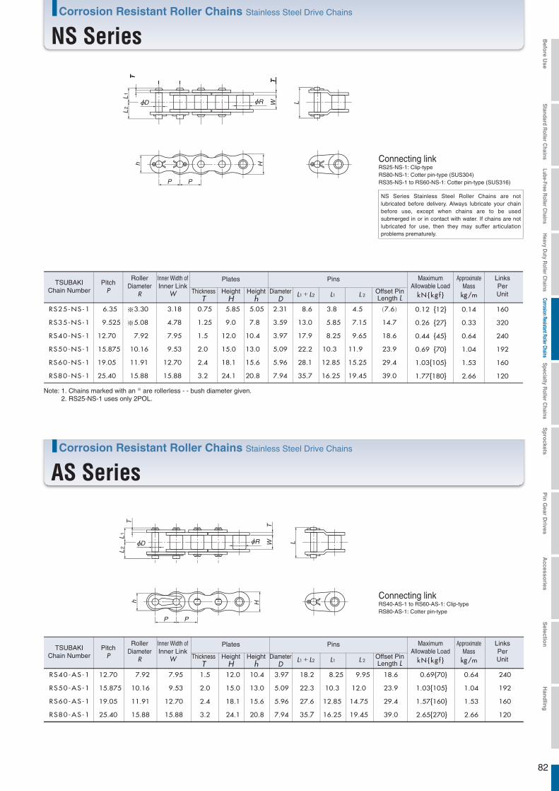
RS40-AS-1 12.70 7.92 7.95 1.5 12.0 10.4 3.97 18.2 8.25 9.95 18.6
RS50-AS-1 15.875 10.16 9.53 2.0 15.0 13.0 5.09 22.3 10.3 12.0 23.9
RS60-AS-1 19.05 11.91 12.70 2.4 18.1 15.6 5.96 27.6 12.85 14.75 29.4
RS80-AS-1 25.40 15.88 15.88 3.2 24.1 20.8 7.94 35.7 16.25 19.45 39.0
0.69{70} 0.64 240
1.03{105} 1.04 192
1.57{160} 1.53 160
2.65{270} 2.66 120
RS25-NS-1 6.35 ※3.30 3.18 0.75 5.85 5.05 2.31 8.6 3.8 4.5 (7.6)
RS35-NS-1 9.525 ※5.08 4.78 1.25 9.0 7.8 3.59 13.0 5.85 7.15 14.7
RS40-NS-1 12.70 7.92 7.95 1.5 12.0 10.4 3.97 17.9 8.25 9.65 18.6
RS80-NS-1 25.40 15.88 15.88 3.2 24.1 20.8 7.94 35.7 16.25 19.45 39.0
RS50-NS-1 15.875 10.16 9.53 2.0 15.0 13.0 5.09 22.2 10.3 11.9 23.9
RS60-NS-1 19.05 11.91 12.70 2.4 18.1 15.6 5.96 28.1 12.85 15.25 29.4
0.12 {12} 0.14 160
0.26 {27} 0.33 320
0.44 {45} 0.64 240
1.77{180} 2.66 120
0.69 {70} 1.04 192
1.03{105} 1.53 160
h
P P
L1
L2
L
T
TW
H
D R
h
P P
L1
L2
L
T
TW
H
D R
Connecting linkRS25-NS-1: Clip-typeRS80-NS-1: Cotter pin-type (SUS304)RS35-NS-1 to RS60-NS-1: Cotter pin-type (SUS316)
Connecting linkRS40-AS-1 to RS60-AS-1: Clip-typeRS80-AS-1: Cotter pin-type
kN{kg f } kg/m
TSUBAKIChain Number
PitchP
RollerDiameter
R
Inner Width ofInner Link
W
Plates Pins
DiameterD
ThicknessT
HeightH
Heighth L1+L2 L1 L 2
Offset PinLength L
MaximumAllowable Load
ApproximateMass
LinksPerUnit
Note: 1. Chains marked with an ※ are rollerless - - bush diameter given.2. RS25-NS-1 uses only 2POL.
kN{kg f } kg/m
TSUBAKIChain Number
PitchP
RollerDiameter
R
Inner Width ofInner Link
W
Plates Pins
DiameterD
ThicknessT
HeightH
Heighth L1+L2 L1 L 2
Offset PinLength L
MaximumAllowable Load
ApproximateMass
LinksPerUnit
NS Series Stainless Steel Roller Chains are not lubricated before delivery. Always lubricate your chain before use, except when chains are to be used submerged in or in contact with water. If chains are not lubricated for use, then they may suffer articulation problems prematurely.
Corrosion Resistant Roller Chains Stainless Steel Drive Chains
NS Series
82
Corrosion Resistant Roller Chains Stainless Steel Drive Chains
AS Series
Befo
re Use
Standard R
oller Chains
Lube-Free Roller C
hainsH
eavy Duty R
oller Chains
Corrosion Resistant Roller ChainsS
pecialty Roller C
hainsS
pro
cketsP
in G
ear Drives
Accesso
riesS
election
Han
dlin
g
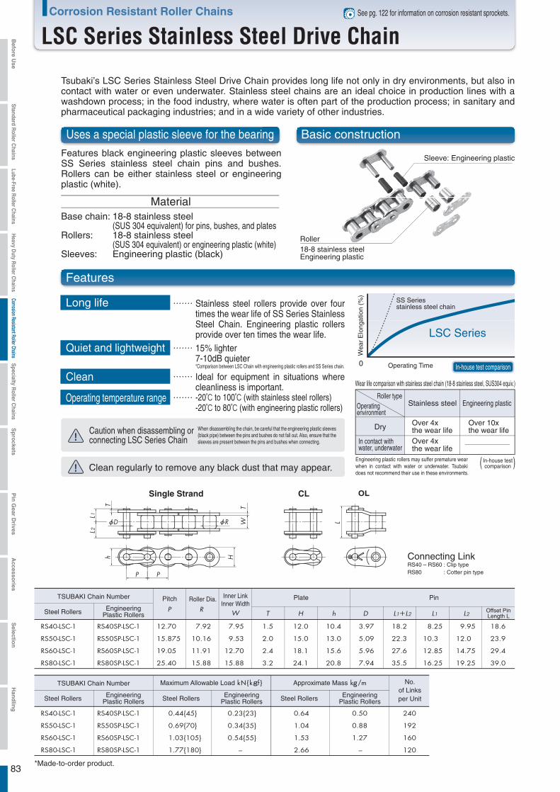
83
Corrosion Resistant Roller Chains
LSC Series Stainless Steel Drive Chain
*Made-to-order product.
See pg. 122 for information on corrosion resistant sprockets.
Tsubaki’s LSC Series Stainless Steel Drive Chain provides long life not only in dry environments, but also in contact with water or even underwater. Stainless steel chains are an ideal choice in production lines with a washdown process; in the food industry, where water is often part of the production process; in sanitary and pharmaceutical packaging industries; and in a wide variety of other industries.
Uses a special plastic sleeve for the bearing
Features black engineering plastic sleeves between SS Series stainless steel chain pins and bushes. Rollers can be either stainless steel or engineering plastic (white).
Stainless steel rollers provide over four times the wear life of SS Series Stainless Steel Chain. Engineering plastic rollers provide over ten times the wear life.
When disassembling the chain, be careful that the engineering plastic sleeves (black pipe) between the pins and bushes do not fall out. Also, ensure that the sleeves are present between the pins and bushes when connecting.
15% lighter7-10dB quieter*Comparison between LSC Chain with engineering plastic rollers and SS Series chain.
Ideal for equipment in situations where cleanliness is important.-20℃ to 100℃ (with stainless steel rollers)-20℃ to 80℃ (with engineering plastic rollers)
MaterialBase chain:
Rollers:
Sleeves:
18-8 stainless steel (SUS 304 equivalent) for pins, bushes, and plates18-8 stainless steel (SUS 304 equivalent) or engineering plastic (white)Engineering plastic (black)
Basic construction
Features
Long life
Quiet and lightweight
Clean
Operating temperature range
Sleeve: Engineering plastic
Roller18-8 stainless steelEngineering plastic
Caution when disassembling or connecting LSC Series Chain
Clean regularly to remove any black dust that may appear.
Wea
r E
long
atio
n (%
)
SS Series stainless steel chain
LSC Series
Operating Time In-house test comparison
Wear life comparison with stainless steel chain (18-8 stainless steel, SUS304 equiv.)
Roller typeOperating environment
Stainless steel Engineering plastic
Dry Over 4x the wear life
Over 10x the wear life
In contact with water, underwater
Over 4x the wear life
Engineering plastic rollers may suffer premature wear when in contact with water or underwater. Tsubaki does not recommend their use in these environments.
In-house testcomparison( )
CLSingle Strand
Connecting LinkRS40 – RS60 : Clip typeRS80 : Cotter pin type
TSUBAKI Chain Number
Steel Rollers EngineeringPlastic Rollers
TSUBAKI Chain Number
Steel Rollers EngineeringPlastic Rollers Steel Rollers Engineering
Plastic Rollers Steel Rollers EngineeringPlastic Rollers
Pitch Roller Dia. Inner LinkInner Width
Plate Pin
Offset PinLength L
kN{kgf }Maximum Allowable Load kg/mApproximate Mass No.of Linksper Unit
Befo
re Use
Standard R
oller Chains
Lube-Free Roller C
hainsH
eavy Duty R
oller Chains
Corrosion Resistant Roller ChainsS
pecialty Roller C
hainsS
pro
cketsP
in G
ear Drives
Accesso
riesS
election
Han
dlin
g

84
RS25-NP-1 6.35 ※3.30 3.18 0.75 5.84 5.05 2.31 8.3 3.8 4.5 7.6
RS35-NP-1 9.525 ※5.08 4.78 1.25 9.0 7.8 3.59 12.7 5.85 6.85 13.5 〃
RS40-NP-1 12.70 7.92 7.95 1.5 12.0 10.4 3.97 18.2 8.25 9.95 18.0 〃
RS50-NP-1 15.875 10.16 9.53 2.0 15.0 13.0 5.09 22.2 10.3 11.9 22.5 〃
RS60-NP-1 19.05 11.91 12.70 2.4 18.1 15.6 5.96 27.6 12.85 14.75 28.2 〃
RS80-NP-1 25.40 15.88 15.88 3.2 24.1 20.8 7.94 35.5 16.25 19.25 36.0 〃
RS100-NP-1 31.75 19.05 19.05 4.0 30.1 26.0 9.54 42.6 19.75 22.85 44.4
RS120-NP-1 38.10 22.23 25.40 4.8 36.2 31.2 11.11 53.8 24.9 28.9 45.4 〃
RS25-NP-1 4.12 {420} 4.7 {480}
RS35-NP-1 9.81{1000} 11.3 {1150}
RS40-NP-1 17.7 {1800} 19.1 {1950}
RS50-NP-1 28.4 {2900} 31.4 {3200}
RS60-NP-1 40.2 {4100} 44.1 {4500}
RS80-NP-1 71.6 {7300} 78.5 {8000}
RS100-NP-1 107 {10900} 118 {12000}
RS120-NP-1 148 {15100} 167 {17000}
0.64 {65} 0.14 160
1.86 {190} 0.33 320
3.04 {310} 0.64 240
5.39 {550} 1.04 192
7.26 {740} 1.53 160
12.7 {1300} 2.66 120
19.1 {1950} 3.99 96
25.5 {2600} 5.93 80
h
P P
L1
L2
L
T
TW
H
D R
Connecting linkRS25-NP-1 to RS60-NP-1: Clip-type (Dual riveting)RS80-NP-1 to RS120-NP-1: Cotter pin-type (Dual riveting)
RS25-NP-1 uses 2POL.
TSUBAKIChain Number
TSUBAKIChain Number
PitchP
RollerDiameter
R
Inner Width ofInner Link
W
Plates Pins
DiameterD
ThicknessT
HeightH
Heighth L1+L2 L1 L 2
Offset PinLength L
Pin type
Riveting
Cotter pin
Minimum TensileStrengthkN{kg f }
Average TensileStrengthkN{kg f }
MaximumAllowable Load
kN{kg f }
ApproximateMasskg/m
Number ofLinks Per Unit
Chains marked with an ※ are rollerless - - bush diameter given.Note: 1. Maximum allowable load when using a one-pitch offset link (OL) is 65% of the above.
1.2.
Do not use surface-treated drive chains if the chains will come in direct contact with food or where flaked coating can contaminate food.Though nickel is not subject to the Food Sanitation Law or Industrial Safety and Health Law, use with caution.
Precautions in Usage
Corrosion Resistant Roller Chains Surface-Treated Drive Chains
NP Series Befo
re Use
Standard R
oller Chains
Lube-Free Roller C
hainsH
eavy Duty R
oller Chains
Corrosion Resistant Roller ChainsS
pecialty Roller C
hainsS
pro
cketsP
in G
ear Drives
Accesso
riesS
election
Han
dlin
g
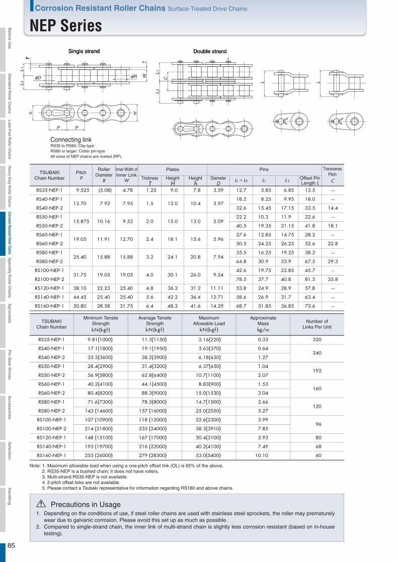
85
RS40-NEP-1 17.1{1800} 19.1{1950} 3.63{370} 0.64240
RS35-NEP-1 9.81{1000} 11.3{1150} 2.16{220} 0.33 320
RS40-NEP-2 35.3{3600} 38.2{3900} 6.18{630} 1.27
RS50-NEP-2 56.9{5800} 62.8{6400} 10.7{1100} 2.07
RS50-NEP-1 28.4{2900} 31.4{3200} 6.37{650} 1.04192
RS60-NEP-2 80.4{8200} 88.3{9000} 15.0{1530} 3.04
RS60-NEP-1 40.2{4100} 44.1{4500} 8.83{900} 1.53160
RS80-NEP-2 143 {14600} 157 {16000} 25.0{2550} 5.27
RS80-NEP-1 71.6{7300} 78.5{8000} 14.7{1500} 2.66120
RS100-NEP-1 107 {10900} 118 {12000} 22.6{2300} 3.9996
RS100-NEP-2 214 {21800} 235 {24000} 38.3{3910} 7.85
RS120-NEP-1 148 {15100} 167 {17000} 30.4{3100} 5.93 80
RS140-NEP-1 193 {19700} 216 {22000} 40.2{4100} 7.49 68
RS160-NEP-1 255 {26000} 279 {28500} 53.0{5400} 10.10 60
RS40-NEP-112.70 7.92 7.95 1.5 12.0 10.4 3.97
18.2 8.25 9.95
RS35-NEP-1 9.525 (5.08) 4.78 1.25 9.0 7.8 3.59 12.7 5.85 6.85
RS40-NEP-2 32.6 15.45 17.15
RS50-NEP-2 40.5 19.35 21.15
RS60-NEP-2 50.5 24.25 26.25
RS80-NEP-2 64.8 30.9 33.9
RS50-NEP-115.875 10.16 9.53 2.0 15.0 13.0 5.09
22.2 10.3 11.9
RS60-NEP-119.05 11.91 12.70 2.4 18.1 15.6 5.96
27.6 12.85 14.75
RS80-NEP-125.40 15.88 15.88 3.2 24.1 20.8 7.94
35.5 16.25 19.25
RS100-NEP-131.75 19.05 19.05 4.0 30.1 26.0 9.54
42.6 19.75 22.85
RS100-NEP-2 78.5 37.7 40.8
RS120-NEP-1 38.10 22.23 25.40 4.8 36.2 31.2 11.11 53.8 24.9 28.9
RS140-NEP-1 44.45 25.40 25.40 5.6 42.2 36.4 12.71 58.6 26.9 31.7
RS160-NEP-1 50.80 28.58 31.75 6.4 48.2 41.6 14.29 68.7 31.85 36.85
18.0
13.5
33.5
41.8
52.6
67.5
22.6
28.2
38.2
45.7
81.5
57.8
63.4
73.6
14.4
18.1
22.8
29.3
35.8
L
h
P P
L1
L2
L1
L2
L
T
TW
H
CD R
Single strand Double strand
Connecting linkRS35 to RS60: Clip-typeRS80 or larger: Cotter pin-typeAll sizes of NEP chains are riveted (RP).
TSUBAKIChain Number
PitchP
RollerDiameter
R
Inner Width ofInner Link
W
Plates Pins
DiameterD
ThicknessT
HeightH
Heighth L1+L2 L1 L 2
Offset PinLength L
TransversePitchC
TSUBAKIChain Number
Minimum TensileStrengthkN{kg f }
Average TensileStrengthkN{kg f }
MaximumAllowable Load
kN{kg f }
ApproximateMasskg/m
Number ofLinks Per Unit
Note: 1. Maximum allowable load when using a one-pitch offset link (OL) is 65% of the above. 2. RS35-NEP is a bushed chain; it does not have rollers.3. Multi-strand RS35-NEP is not available.
1.
2.
Depending on the conditions of use, if steel roller chains are used with stainless steel sprockets, the roller may prematurely wear due to galvanic corrosion. Please avoid this set up as much as possible. Compared to single-strand chain, the inner link of multi-strand chain is slightly less corrosion resistant (based on in-house testing).
Precautions in Usage
4. 2-pitch offset links are not available.5. Please contact a Tsubaki representative for information regarding RS180 and above chains.
Corrosion Resistant Roller Chains Surface-Treated Drive Chains
NEP SeriesBefo
re Use
Standard R
oller Chains
Lube-Free Roller C
hainsH
eavy Duty R
oller Chains
Corrosion Resistant Roller ChainsS
pecialty Roller C
hainsS
pro
cketsP
in G
ear Drives
Accesso
riesS
election
Han
dlin
g

86
Opposite side of worn surface Worn surface
Initiation point
Anti-Pitting Roller Chain
Outstanding performance in atmospheres conducive to pitting corrosion
Note: Pitting is a type of localized corrosion affecting metal surfaces. Pits form toward the interior, and if pitting occurs on pin surfaces, that pin can quickly lead to fatigue breakage and chain failure.
Pins are treated with a special surface treatment to protect against pitting corrosion that leads to fatigue breakage, thus preventing strength loss. This treatment is highly effective in environments that readily promote corrosion, such as outdoors or in coastal applications.
Features No strength loss! Eco-friendly chrome-free!Special surface treatment does not use hazardoushexavalent chromium.
Same as standard steel chain.
Example applications
Examples of fatigue breakage caused by pitting corrosion
Applicable models
Chain number
APP Chains are ideal for atmospheres that readily promote corrosion.Outdoor uses Coastal or riverside uses When regular lubrication is difficult
Bucket elevators Transfer cranes and other port machinery
Because equipment is used outdoors, rain can infiltrate gaps in covers, creating conditions that promote pitting corrosion.
Pitting readily occurs in equipment exposed to salty air or saltwater spray.
Chain: RS240 Equipment: Port container carrierPitting corrosion of the pin due to insufficient lubrication (effects of salty air and saltwater) and corrosive atmosphere - - Fatigue breakage
Pin breakage
Enlarged viewof fracture surface
Enlarged viewof breakage Secondary fracture in link plate
Initiation point
Load can become imbalanced after pin breakage, leading to secondary breaks in plates.Pitting corrosion readily
occurs on the opposite side of the bush wear surface.
Pitting was observed in more than one location.
Single/Double Strand RS Roller Chain (For other models, contact a Tsubaki representative.)Single Strand Heavy Duty Roller ChainExcept for the surface-treated pins, dimensions and other specifications are the same as other roller chains.
Note: Select connecting link (CL).
Corrosion Resistant Roller Chains Surface-Treated Drive Chains
APP Series Befo
re Use
Standard R
oller Chains
Lube-Free Roller C
hainsH
eavy Duty R
oller Chains
Corrosion Resistant Roller ChainsS
pecialty Roller C
hainsS
pro
cketsP
in G
ear Drives
Accesso
riesS
election
Han
dlin
g
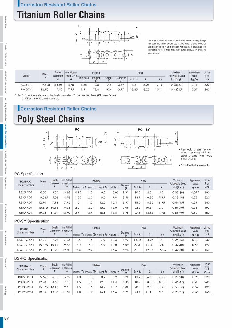
87
RS35-TI-1 9.525 ※5.08 4.78 1.25 9.0 7.8 3.59 13.2 6.05 7.15 0.26{27} 0.19 320
RS40-TI-1 12.70 7.92 7.95 1.5 12.0 10.4 3.97 18.35 8.25 10.1 0.44{45} 0.37 240
h
P P
L1
L2
T
TW
H
D R
PitchP
RollerDiameter
R
Inner Width ofInner Link
W
Plates Pins
DiameterD
ThicknessT
HeightH
Heighth L1+L2 L1 L 2 kN{kg f }
MaximumAllowable Load
kg/m
ApproximateMass
LinksPerUnit
Model
Note: 1. The figure shown is the bush diameter. 2. Connecting links (CL) use Z-pins.3. Offset links are not available.
RS25-PC-1 6.35 3.30 3.18 0.75 1.3 6.0 5.05 2.31 10.0 4.5 5.5 0.08 {8} 0.095 160
RS35-PC-1 9.525 5.08 4.78 1.25 2.2 9.0 7.8 3.59 14.7 6.85 7.85 0.18{18} 0.22 320
RS40-PC-1 12.70 7.92 7.95 1.5 1.5 12.0 10.4 3.97 18.2 8.25 9.95 0.44{45} 0.39 240
RS50-PC-1 15.875 10.16 9.53 2.0 2.0 15.0 13.0 5.09 22.3 10.3 12.0 0.69{70} 0.58 192
RS60-PC-1 19.05 11.91 12.70 2.4 2.4 18.1 15.6 5.96 27.6 12.85 14.75 0.88{90} 0.82 160
RS40-PC-SY-1 12.70 7.92 7.95 1.5 1.5 12.0 10.4 3.97 18.35 8.25 10.1 0.25{25} 0.39 240
RS50-PC-SY-1 15.875 10.16 9.53 2.0 2.0 15.0 13.0 5.09 22.3 10.3 12.0 0.39{40} 0.58 192
RS60-PC-SY-1 19.05 11.91 12.70 2.4 2.4 18.1 15.6 5.96 28.1 12.85 15.25 0.49{50} 0.82 160
h
P PHh
P P
H
-
L1
L2
T1
T2
W
L1
L2
T1
T2
WD R D R
TSUBAKIChain Number
PitchP
BushDiameter
R
BushDiameter
R
Inner Width ofInner Link
W
Plates
Thickness T1 Thickness T2 Height H Height h kN{kg f } kg/m
Pins
DiameterD L1+L2 L1 L 2
MaximumAllowable Load
ApproximateMass
LinksPerUnit
Recheck chain tension when replacing stainless steel chains with Poly Steel chains.
No offset links available.
TSUBAKIChain Number
PitchP
Inner Width ofInner Link
W
Plates
Thickness T1 Thickness T2 Height H Height h kN{kg f } kg/m
Pins
DiameterD L1+L2 L1 L 2
MaximumAllowable Load
ApproximateMass
LinksPerUnit
PC Specification
RF06B-PC-1 9.525 6.35 5.72 1.0 1.3 8.2 8.2 3.28 13.75 6.5 7.25 0.20{20} 0.23 320
RS08B-PC-1 12.70 8.51 7.75 1.5 1.6 12.0 11.4 4.45 18.4 8.35 10.05 0.46{47} 0.4 240
RS10B-PC-1 15.875 10.16 9.65 1.5 1.5 14.7 13.7 5.08 20.8 9.55 11.25 0.53{54} 0.52 192
RS12B-PC-1 19.05 12.07 11.68 1.8 1.8 16.1 15.6 5.72 24.1 11.1 13.0 0.70{71} 0.65 160
TSUBAKIChain Number
PitchP
BushDiameter
R
Inner Width ofInner Link
W
Plates
Thickness T1 Thickness T2 Height H Height h kN{kg f } kg/m
Pins
DiameterD L1+L2 L1 L 2
MaximumAllowable Load
ApproximateMass
LinksPerUnit(3m)
BS-PC Specification
PC-SY Specification
Titanium Roller Chains are not lubricated before delivery. Always lubricate your chain before use, except when chains are to be used submerged in or in contact with water. If chains are not lubricated for use, then they may suffer articulation problems prematurely.
Corrosion Resistant Roller Chains
Titanium Roller Chains
Corrosion Resistant Roller Chains
Poly Steel Chains
Befo
re Use
Standard R
oller Chains
Lube-Free Roller C
hainsH
eavy Duty R
oller Chains
Corrosion Resistant Roller ChainsS
pecialty Roller C
hainsS
pro
cketsP
in G
ear Drives
Accesso
riesS
election
Han
dlin
g
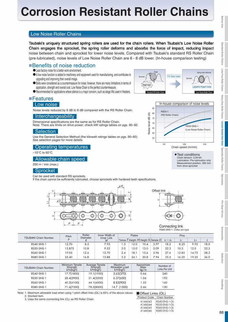
88
Less factory noise for a better work environment.A low noise function is added to machinery and equipment used for manufacturing, and contributes to upgrading and improving their overall image.Belts were considered as a countermeasure for noise; however, there are many limitations in terms of application, strength and overall cost. Low Noise Chain is the perfect countermeasure.Recommended for applications where silence is a major concern, such as stage lifts used in theaters.
Dimensional specifications are the same as for RS Roller Chain.Note: There are limits on drive power; check kW ratings tables on pgs. 90–92.
Interchangeability
Use the General Selection Method (the kilowatt ratings tables on pgs. 90–92).See selection pages for more details.
Selection
–10°C to 60°C
Operating temperatures
200 m / min (max.)
Allowable chain speed
Can be used with standard RS sprockets.If the chain cannot be sufficiently lubricated, choose sprockets with hardered teeth specifications.
Sprocket
Tsubaki's uniquely structured spring rollers are used for the chain rollers. When Tsubaki's Low Noise Roller Chain engages the sprocket, the spring roller deforms and absorbs the force of impact, reducing impact noise between chain and sprocket for lower noise levels. Compared with Tsubaki's standard RS Roller Chain (pre-lubricated), noise levels of Low Noise Roller Chain are 6 - 8 dB lower. (In-house comparison testing)
Benefits of noise reduction
FeaturesLow Noise Roller Chain
SprocketSprocket
Roller
Impact noise
Standard RS Roller Chain
For less noise
Spring roller (deforms)
Lessens impact noise
Low noiseNoise levels reduced by 6 dB to 8 dB compared with the RS Roller Chain.
50
Noi
se le
vel d
B (
A)
50
60
65
70
75
80
85
100 150
Chain speed (m/min)
In-house comparison of noise levels
RS50-1
(RS Roller Chain)
RS50-SNS-1
(Low Noise Roller Chain)
Chain tension: 3.29 kNLubrication: Pre-lubrication onlyMeasurement position: 300 mm from drive sprocket
Test conditions
Corrosion Resistant Roller Chains
Low Noise Roller Chains
φD
φR
L
LRS40-SNS-1 12.70 8.5 7.95 1.5 12.0 10.4 3.97 18.2 8.25 9.95 18.0
RS50-SNS-1 15.875 10.8 9.53 2.0 15.0 13.0 5.09 22.3 10.3 12.0 22.5
RS60-SNS-1 19.05 12.6 12.70 2.4 18.1 15.6 5.96 27.6 12.85 14.75 28.2
RS80-SNS-1 25.40 16.8 15.88 3.2 24.1 20.8 7.94 35.5 16.25 19.25 36.0
L1
L2
T TW
h H
P P
17.7{1800} 19.1{1950} 3.63{370} 0.64 240
28.4{2900} 31.4{3200} 6.37{650} 1.04 192
40.2{4100} 44.1{4500} 8.83{900} 1.53 160
71.6{7300} 78.5{8000} 14.7 {1500} 2.66 120
RS40-SNS-1
RS50-SNS-1
RS60-SNS-1
RS80-SNS-1
Connecting linkRS80-SNS-1: Cotter pin-type
Offset link
TSUBAKI Chain Number
TSUBAKI Chain Number
PitchP
RollerDiameter
R
Inner Width ofInner Link
W
Plates Pins
Diameter DThickness T Height H Height h L1+L2 L1 L 2
Minimum TensileStrengthkN{kg f }
Average TensileStrengthkN{kg f }
MaximumAllowable Load
kN{kg f }
ApproximateMasskg/m
Number ofLinks Per Unit
Note: 1. Maximum allowable load when using 1-pitch offset links (OL) is 65% of the above values.2. Stocked item.3. Uses the same connecting link (CL) as RS Roller Chain.
Offset Links (OL)Product Code Chain Number
Befo
re Use
Standard R
oller Chains
Lube-Free Roller C
hainsH
eavy Duty R
oller Chains
Corrosion Resistant Roller ChainsS
pecialty Roller C
hainsS
pro
cketsP
in G
ear Drives
Accesso
riesS
election
Han
dlin
g

89
Corrosion Resistant Roller Chains Surface-Treated Drive Chains
Kilowatt Ratings Tables(RS40-SNS-1~RS80-SNS-1)
Note: With a one-pitch offset link kW ratings are 80% of that shown above.
10 25 50 100 200 300 400 500 700 900 1000 1200 1400 1600
0.050.050.060.070.07
0.080.080.090.100.10
0.110.120.120.130.13
0.140.150.150.170.18
0.190.210.240.28
0.110.120.140.150.17
0.180.190.210.220.23
0.250.260.280.290.31
0.320.330.350.380.41
0.440.480.560.63
0.210.230.260.280.31
0.330.360.390.410.44
0.460.490.520.540.57
0.600.620.650.710.76
0.810.901.041.18
0.390.430.480.530.57
0.620.670.720.770.82
0.870.920.961.011.06
1.111.161.211.321.42
1.521.671.932.20
0.720.810.900.981.07
1.161.251.341.431.52
1.621.711.801.891.99
2.082.172.272.462.65
2.843.133.614.10
1.041.161.291.421.54
1.671.801.932.062.20
2.332.462.592.732.86
3.003.133.273.543.81
4.094.505.205.91
1.351.511.671.842.00
2.172.342.502.672.84
3.023.193.363.533.71
3.884.064.234.584.94
5.295.83
1.641.842.042.242.45
2.652.863.063.273.48
3.693.904.114.324.53
4.744.965.175.606.04
1.061.251.441.641.85
2.062.292.522.763.01
3.263.523.794.06
0.730.850.991.121.27
1.421.571.731.89
0.620.730.840.961.08
1.211.34
0.470.550.640.730.82
0.380.440.51
0.31910111213
1415161718
1920212223
2425262830
32354045
Oiled or with drip-oiling system
Small Sprocket Max rpmSmall Sprocket
Lubrication Type
No. of Teeth Oil bath
RS40-SNS-1 Maximum Kilowatt Ratings Table (kW Ratings for Single Strand Chain)
10 25 50 100 150 200 300 400 500 600 700 800 900 1000 1100
0.180.200.220.240.26
0.290.310.330.350.38
0.400.420.440.470.49
0.510.540.560.610.65
0.700.770.891.01
0.410.450.500.550.60
0.650.700.750.810.86
0.910.961.011.061.12
1.171.221.281.381.49
1.601.762.032.31
0.760.850.941.031.13
1.221.311.411.501.60
1.701.791.891.992.08
2.182.282.382.582.78
2.983.283.794.30
1.411.581.751.932.10
2.282.452.632.812.98
3.163.343.533.713.89
4.074.264.444.815.18
5.566.127.078.03
2.032.282.532.773.03
3.283.533.794.044.30
4.564.825.085.345.60
5.876.136.406.937.46
8.008.8210.211.6
2.632.593.273.593.92
4.254.574.905.245.57
5.906.246.586.927.26
7.607.948.298.989.67
10.411.413.215.0
3.794.254.715.185.65
6.126.597.067.548.02
8.518.999.489.9610.5
10.911.411.912.913.9
14.9
3.413.994.605.245.91
6.617.338.078.849.63
10.411.312.112.913.5
14.214.815.5
2.442.853.293.794.23
4.735.245.786.336.89
7.478.07
1.852.172.502.853.22
3.603.994.394.81
1.471.721.992.262.55
2.85
1.201.411.631.852.09
1.011.181.36
0.861.01
0.75910111213
1415161718
1920212223
2425262830
32354045
10 25 50 100 200 300 400 500 700 900 1000 1200
0.100.110.120.140.15
0.160.170.190.200.21
0.230.240.250.260.28
0.290.300.320.340.37
0.400.440.500.57
0.230.260.280.310.34
0.370.400.430.460.49
0.510.540.570.600.63
0.660.690.720.780.84
0.900.991.151.30
0.430.480.530.580.64
0.690.740.800.850.91
0.961.011.071.121.18
1.241.291.351.461.57
1.691.862.142.44
0.800.900.991.091.19
1.291.391.491.591.69
1.791.892.002.102.20
2.302.412.512.722.93
3.143.464.004.54
1.491.671.852.032.22
2.402.592.782.963.15
3.343.533.723.914.11
4.304.494.695.085.47
5.876.467.478.48
2.152.412.672.933.19
3.463.734.004.274.54
4.815.095.365.645.92
6.196.476.757.327.88
8.459.3110.8
2.783.123.463.804.14
4.484.835.185.535.88
6.246.596.957.317.66
8.038.398.759.4810.2
2.112.472.853.243.66
4.094.534.995.475.96
6.466.987.518.058.60
9.179.75
1.271.491.721.962.21
2.472.743.013.30
0.871.021.181.341.51
0.740.871.011.15
0.570.66
910111213
1415161718
1920212223
2425262830
32354045
Oiled or with drip-oiling system
Small Sprocket Max rpmSmall Sprocket
Lubrication Type
No. of Teeth
Oiled or with drip-oiling system
Small Sprocket Max rpmSmall Sprocket
Lubrication Type
No. of Teeth
RS50-SNS-1 Maximum Kilowatt Ratings Table (kW Ratings for Single Strand Chain)
RS60-SNS-1 Maximum Kilowatt Ratings Table (kW Ratings for Single Strand Chain)
Oil bath
Oil bath
10 25 50 100 150 200 300 400 500 600 700 800
0.400.450.490.540.59
0.640.690.740.790.84
0.890.940.991.041.10
1.151.201.251.361.46
1.571.731.992.26
0.911.021.131.241.35
1.461.581.691.801.92
2.032.152.272.382.50
2.622.742.853.093.33
3.573.944.555.16
1.691.902.102.312.52
2.732.943.153.373.58
3.804.014.234.454.67
4.895.115.335.776.22
6.677.348.489.63
3.163.543.934.314.70
5.095.495.886.286.68
7.087.497.898.308.71
9.129.539.9410.811.6
12.413.715.818.0
4.555.105.656.216.77
7.347.908.489.059.63
10.210.811.412.012.5
13.113.714.315.516.7
17.919.722.825.9
5.906.617.338.058.77
9.5110.211.011.712.5
13.214.014.715.516.2
17.017.818.520.121.6
23.225.6
6.607.738.9210.211.5
12.814.215.616.918.0
19.020.121.222.323.4
24.525.626.7
4.295.025.796.607.44
8.329.2210.211.112.1
13.1
3.073.594.144.725.33
5.956.60
2.332.733.153.594.05
1.852.172.50
1.52910111213
1415161718
1920212223
2425262830
32354045
Oiled or with drip-oiling system
Small Sprocket Max rpmSmall Sprocket
Lubrication Type
No. of Teeth
RS80-SNS-1 Maximum Kilowatt Ratings Table (kW Ratings for Single Strand Chain)
Oil bath
Befo
re Use
Standard R
oller Chains
Lube-Free Roller C
hainsH
eavy Duty R
oller Chains
Corrosion Resistant Roller ChainsS
pecialty Roller C
hainsS
pro
cketsP
in G
ear Drives
Accesso
riesS
election
Han
dlin
g

90
RS35-KT-1 9.81{1000} 11.3{1150} 2.16{220} 0.33 320RS40-KT-1 17.7 {1800} 19.1{1950} 3.63{370} 0.64 240RS50-KT-1 28.4 {2900} 31.4{3200} 6.37{650} 1.04 192RS60-KT-1 40.2 {4100} 44.1{4500} 8.83{900} 1.53 160RS80-KT-1 71.6 {7300} 78.5{8000} 14.7{1500} 2.66 120RS100-KT-1 107 {10900} 118 {12000} 22.6{2300} 3.99 96
RS140-KT-1 193 {19700} 216 {22000} 40.2{4100} 7.49 68RS120-KT-1 148 {15100} 167 {17000} 30.4{3100} 5.93 80
RS160-KT-1 255 {26000} 279 {28500} 53.0{5400} 10.10 60
RS35-KT-1 9.525 ※5.08 4.78 1.25 9.0 7.8 3.59 12.9 5.85 7.05 13.5RS40-KT-1 12.70 7.92 7.95 1.5 12.0 10.4 3.97 17.9 8.25 9.65 18.0RS50-KT-1 15.875 10.16 9.53 2.0 15.0 13.0 5.09 22.2 10.3 11.9 23.7RS60-KT-1 19.05 11.91 12.70 2.4 18.1 15.6 5.96 28.1 12.85 15.25 28.2RS80-KT-1 25.40 15.88 15.88 3.2 24.1 20.8 7.94 35.5 16.25 19.25 36.6
RS100-KT-1 31.75 19.05 19.05 4.0 30.1 26.0 9.54 42.6 19.75 22.85 43.7
RS140-KT-1 44.45 25.40 25.40 5.6 42.2 36.4 12.71 58.6 26.9 31.7 62.8RS120-KT-1 38.10 22.23 25.40 4.8 36.2 31.2 11.11 53.8 24.9 28.9 55.0
RS160-KT-1 50.80 28.58 31.75 6.4 48.2 41.6 14.29 68.7 31.85 36.85 70.2
h
P P
L1
L2
L
T
TW
H
D R
PitchP
RollerDiameter
R
Inner Width ofInner Link
W
Plates Pins
DiameterD
ThicknessT
HeightH
Heighth L1+L2 L1 L 2
ModelOffset PinLength L
ModelMinimum Tensile
StrengthkN{kg f }
Average TensileStrengthkN{kg f }
MaximumAllowable Load
kN{kg f }
ApproximateMasskg/m
Number ofLinks Per Unit
Note: 1. Values marked with * are rollerless.2. Offset pin shape varies according to size.3. Maximum allowable load when using MCL is 80% of the above values.4. Maximum allowable load when using 1-pitch offset links (OL) is 65% of the above values.5. Normally, chains are coated only with anti-rust oil when shipped. Chain should be lubricated with an oil suitable to the ambient temperature
during actual use. Customized models that are coated with a silicon (low temperature) oil are also available.
RS40-CU-SS-1 12.70 7.92 7.95 1.5 12.0 10.4 3.59 18.1 8.35 9.75 400 0.26 {27} 0.61 240
RS50-CU-SS-1 15.875 10.16 9.53 2.0 15.0 13.0 3.97 22.2 10.15 12.05 500 0.44 {45} 1.01 192
RS60-CU-SS-1 19.05 11.91 12.70 2.4 18.1 15.6 5.09 28.3 13.25 15.05 600 0.69 {70} 1.40 160
RS80-CU-SS-1 25.40 15.88 15.88 3.2 24.1 20.8 5.96 35.0 16.5 18.5 800 1.03{105} 2.47 120
Stainless Steel (SUS304) Specification
PitchP
RollerDiameter
R
Inner Width ofInner Link
W
Plates Pins
DiameterD
ThicknessT
HeightH
Heighth L1+L2 L1 L 2
ModelMaximum
Allowable LoadkN{kg f }
ApproximateMasskg/m
LinksPerUnit
Min.Radius
r
Note: 1. Made-to-order product.
L1
L2
T
TW
r
D R
h
P P
H
Curved Stainless Steel Roller Chains are not lubricated before delivery. Always lubricate your chain before use, except when chains are to be used submerged in or in contact with water. If chains are not lubricated for use, then they may suffer articulation problems prematurely.
Corrosion Resistant Roller Chains
Cold Resistant Roller Chains
Corrosion Resistant Roller Chains
Curved Stainless Steel Roller Chain
Befo
re Use
Standard R
oller Chains
Lube-Free Roller C
hainsH
eavy Duty R
oller Chains
Corrosion Resistant Roller ChainsS
pecialty Roller C
hainsS
pro
cketsP
in G
ear Drives
Accesso
riesS
election
Han
dlin
g
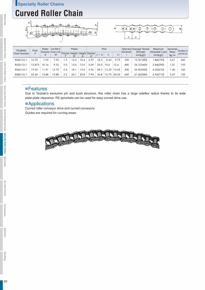
91
RS40-CU-1 12.70 7.92 7.95 1.5 12.0 10.4 3.97 18.2 8.45 9.75 350 15.5{1580} 1.86{190} 0.61 240
RS50-CU-1 15.875 10.16 9.53 2.0 15.0 13.0 5.09 23.0 10.6 12.4 400 24.1{2460} 2.84{290} 1.01 192
RS60-CU-1 19.05 11.91 12.70 2.4 18.1 15.6 5.96 28.3 13.25 15.05 500 34.9{3560} 4.02{410} 1.40 160
RS80-CU-1 25.40 15.88 15.88 3.2 24.1 20.8 7.94 36.8 16.75 20.05 600 61.6{6280} 6.96{710} 2.47 120
Due to Tsubaki's exclusive pin and bush structure, this roller chain has a large sideflex radius thanks to its wide plate-plate clearance. RS sprockets can be used for easy curved drive use.
D
L1
L2
T
r
R
TW
h H
P P
PitchP
RollerDiameter
R
Inner Width ofInner Link
W
Plates Pins
DiameterD
ThicknessT
HeightH
Heighth L1+L2 L1 L 2
MaximumAllowable Load
kN{kg f }
ApproximateMasskg/m
Number ofLinks Per Unit
Tightest lateralbend diameter
r
TSUBAKIChain Number
Features
Curved roller conveyor drive and curved conveyors.Guides are required for curving areas.
Applications
Average TensileStrengthkN{kg f }
Specialty Roller Chains
Curved Roller ChainBefo
re Use
Standard R
oller Chains
Lube-Free Roller C
hainsH
eavy Duty R
oller Chains
Corrosion Resistant Roller ChainsS
pecialty Roller C
hainsS
pro
cketsP
in G
ear Drives
Accesso
riesS
election
Han
dlin
g
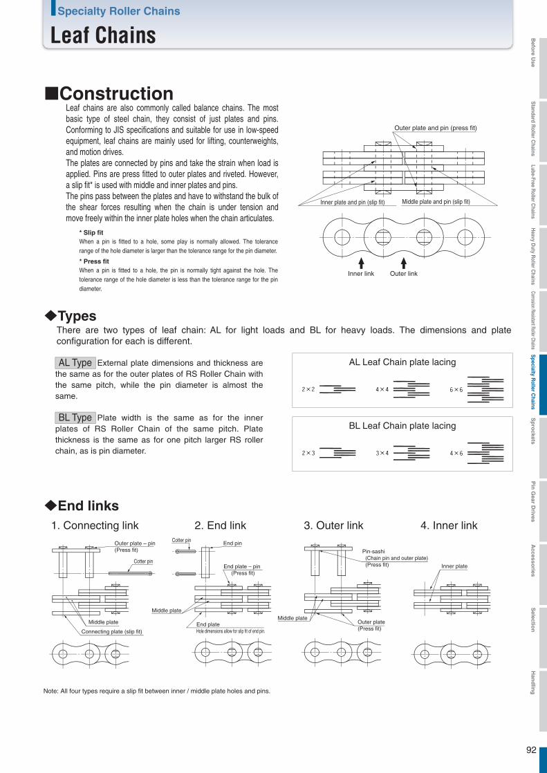
92
External plate dimensions and thickness are the same as for the outer plates of RS Roller Chain with the same pitch, while the pin diameter is almost the same.
Middle plate
ConstructionLeaf chains are also commonly called balance chains. The most basic type of steel chain, they consist of just plates and pins. Conforming to JIS specifications and suitable for use in low-speed equipment, leaf chains are mainly used for lifting, counterweights, and motion drives.The plates are connected by pins and take the strain when load is applied. Pins are press fitted to outer plates and riveted. However, a slip fit* is used with middle and inner plates and pins.The pins pass between the plates and have to withstand the bulk of the shear forces resulting when the chain is under tension and move freely within the inner plate holes when the chain articulates.
* Slip fitWhen a pin is fitted to a hole, some play is normally allowed. The tolerance range of the hole diameter is larger than the tolerance range for the pin diameter.
* Press fitWhen a pin is fitted to a hole, the pin is normally tight against the hole. The tolerance range of the hole diameter is less than the tolerance range for the pin diameter.
Outer plate and pin (press fit)
Inner plate and pin (slip fit) Middle plate and pin (slip fit)
Inner link Outer link
Types
End links
There are two types of leaf chain: AL for light loads and BL for heavy loads. The dimensions and plate configuration for each is different.
AL Type
Plate width is the same as for the inner plates of RS Roller Chain of the same pitch. Plate thickness is the same as for one pitch larger RS roller chain, as is pin diameter.
BL Type
AL Leaf Chain plate lacing
BL Leaf Chain plate lacing
Outer plate – pin(Press fit)
Cotter pin
Middle plate
Connecting plate (slip fit)
1. Connecting link 2. End link
Pin-sashi (Chain pin and outer plate) (Press fit)
Outer plate(Press fit)
Inner plate
Note: All four types require a slip fit between inner / middle plate holes and pins.
3. Outer link 4. Inner linkCotter pin End pin
Middle plate
End plate – pin (Press fit)
End plate Hole dimensions allow for slip fit of end pin.
Specialty Roller Chains
Leaf Chains Befo
re Use
Standard R
oller Chains
Lube-Free Roller C
hainsH
eavy Duty R
oller Chains
Corrosion Resistant Roller ChainsS
pecialty Roller C
hainsS
pro
cketsP
in G
ear Drives
Accesso
riesS
election
Han
dlin
g
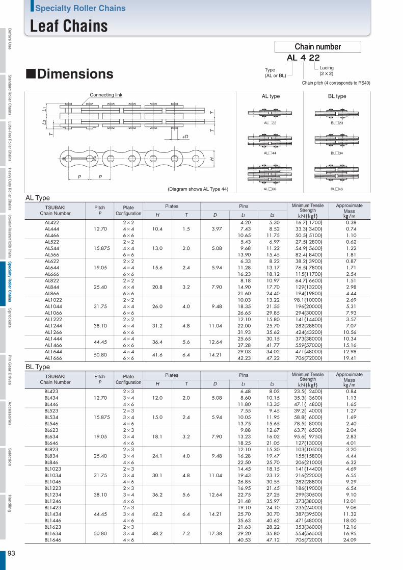
93
kN{kg f }H T D L1 L2
AL42212.70
2×210.4 1.5 3.97
4.20 5.30 16.7{ 1700} 0.38AL444 4×4 7.43 8.52 33.3{ 3400} 0.74AL466 6×6 10.65 11.75 50.5{ 5100} 1.10AL522
15.8752×2
13.0 2.0 5.085.43 6.97 27.5{ 2800} 0.62
AL544 4×4 9.68 11.22 54.9{ 5600} 1.22AL566 6×6 13.90 15.45 82.4{ 8400} 1.81AL622
19.052×2
15.6 2.4 5.946.33 8.22 38.2{ 3900} 0.87
AL644 4×4 11.28 13.17 76.5{ 7800} 1.71AL666 6×6 16.23 18.12 115{11700} 2.54AL822
25.402×2
20.8 3.2 7.908.18 10.97 64.7{ 6600} 1.51
AL844 4×4 14.90 17.70 129{13200} 2.98AL866 6×6 21.60 24.40 194{19800} 4.44AL1022
31.752×2
26.0 4.0 9.4810.03 13.22 98.1{10000} 2.69
AL1044 4×4 18.35 21.55 196{20000} 5.31AL1066 6×6 26.65 29.85 294{30000} 7.93AL1222
38.102×2
31.2 4.8 11.0412.10 15.80 141{14400} 3.57
AL1244 4×4 22.00 25.70 282{28800} 7.07AL1266 6×6 31.93 35.62 424{43200} 10.56AL1444
44.454×4
36.4 5.6 12.6425.65 30.15 373{38000} 10.34
AL1466 6×6 37.28 41.77 559{57000} 15.16AL1644
50.804×4
41.6 6.4 14.2129.03 34.02 471{48000} 12.98
AL1666 6×6 42.23 47.22 706{72000} 19.41
BL42312.70
2×312.0 2.0 5.08
6.48 8.02 23.5{ 2400} 0.84BL434 3×4 8.60 10.15 35.3{ 3600} 1.13BL446 4×6 11.80 13.35 47.1{ 4800} 1.65BL523
15.8752×3
15.0 2.4 5.947.55 9.45 39.2{ 4000} 1.27
BL534 3×4 10.05 11.95 58.8{ 6000} 1.69BL546 4×6 13.75 15.65 78.5{ 8000} 2.40BL623
19.052×3
18.1 3.2 7.909.88 12.67 63.7{ 6500} 2.04
BL634 3×4 13.23 16.02 95.6{ 9750} 2.83BL646 4×6 18.25 21.05 127{13000} 4.01BL823
25.402×3
24.1 4.0 9.4812.10 15.30 103{10500} 3.20
BL834 3×4 16.28 19.47 155{15800} 4.44BL846 4×6 22.50 25.70 206{21000} 6.32BL1023
31.752×3
30.1 4.8 11.0414.45 18.15 141{14400} 4.69
BL1034 3×4 19.43 23.12 216{22000} 6.55BL1046 4×6 26.85 30.55 282{28800} 9.29BL1223
38.102×3
36.2 5.6 12.6416.95 21.45 186{19000} 6.54
BL1234 3×4 22.75 27.25 299{30500} 9.10BL1246 4×6 31.48 35.97 373{38000} 12.01BL1423
44.452×3
42.2 6.4 14.2119.10 24.10 235{24000} 9.06
BL1434 3×4 25.70 30.70 387{39500} 11.32BL1446 4×6 35.63 40.62 471{48000} 18.00BL1623
50.802×3
48.2 7.2 17.3821.63 28.22 353{36000} 12.16
BL1634 3×4 29.20 35.80 554{56500} 16.95BL1646 4×6 40.53 47.12 706{72000} 24.09
L1
L2
T
P P
TT
H
D
Chain number
Type(AL or BL)
Lacing(2 x 2)
Chain pitch (4 corresponds to RS40)Dimensions
Connecting link AL type
AL Type
BL type
BL Type
(Diagram shows AL Type 44)
PlateConfiguration
Minimum TensileStrengthPitch
PPlates PinsTSUBAKI
Chain Number
ApproximateMasskg/m
kN{kg f }H T D L1 L2
PlateConfiguration
Minimum TensileStrengthPitch
PPlates PinsTSUBAKI
Chain Number
ApproximateMasskg/m
Specialty Roller Chains
Leaf ChainsBefo
re Use
Standard R
oller Chains
Lube-Free Roller C
hainsH
eavy Duty R
oller Chains
Corrosion Resistant Roller ChainsS
pecialty Roller C
hainsS
pro
cketsP
in G
ear Drives
Accesso
riesS
election
Han
dlin
g
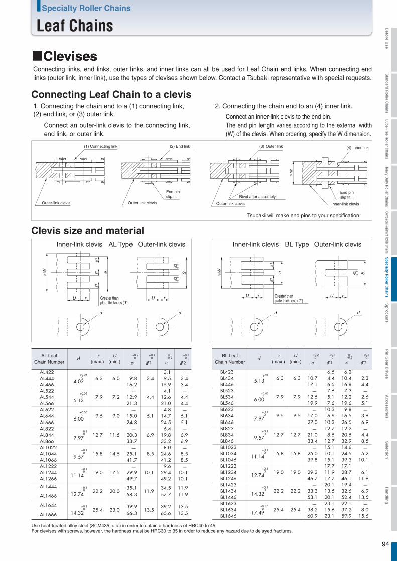
94
d r U +0.20
e
+0.10
g 1
0-0.2
s
+0.10
g 2
AL422+0.05
0
4.026.3 6.0
3.4
3.1 9.8 9.5 3.4
16.2 15.9 3.4AL522
+0.05 0
5.137.9 7.2
4.4
4.1 12.9 12.6 4.421.3 21.0 4.4
AL622+0.05
0
6.009.5 9.0
5.1
4.8 15.0 14.7 5.124.8 24.5 5.1
AL822+0.1
0
7.9712.7 11.5
6.9
6.4 20.3 19.8 6.933.7 33.2 6.9
AL1022+0.1
0
9.5715.8 14.5
8.5
8.0 25.1 24.6 8.541.7 41.2 8.5
AL1222+0.1
0
11.1419.0 17.5
10.1
9.6 29.9 29.4 10.149.7 49.2 10.1
AL1444 +0.1 0
12.7422.2 20.0
35.111.9
34.5 11.9
AL1466 58.3 57.7 11.9
AL1644 +0.1 0
14.3225.4 23.0
39.913.5
39.2 13.5
AL1666 66.3 65.6 13.5
AL444AL466
AL544AL566
AL644AL666
AL844AL866
AL1044AL1066
AL1244AL1266
dr U +0.2
0
e
+0.10
g 1
0-0.2
s
+0.10
g 2
BL423+0.05
0
5.13 6.3 6.3 6.5 6.2
10.7 10.4 2.317.1 16.8 4.4
BL523+0.05
0
6.00 7.9 7.9 7.6 7.3
12.5 12.2 2.619.9 19.6 5.1
BL623+0.1 0
7.979.5 9.5
10.3 9.8 17.0 16.5 3.627.0 26.5 6.9
BL823+0.1 0
9.5712.7 12.7
12.7 12.2 21.0 20.5 4.433.4 32.9 8.5
BL1023+0.1 0
11.1415.8 15.8
15.1 14.6 25.0 24.5 5.239.8 39.3 10.1
BL1623+0.15
0
17.4925.4 25.4
23.1 22.1 38.2 37.2 8.060.9 59.9 15.6
BL434BL446
BL534BL546
BL634BL646
BL834BL846
BL1034BL1046
BL1634BL1646
BL1223+0.1 0
12.7419.0 19.0
17.7 17.1 BL1234 29.3 28.7 6.1BL1246 46.7 46.1 11.9BL1423
+0.1 0
14.3222.2 22.2
20.1 19.4 BL1434 33.3 32.6 6.9BL1446 53.1 52.4 13.5
4.46.5
5.17.6
6.910.3
8.512.7
10.115.1
11.917.7
13.520.1
15.623.1
11
1
eW
U r
d
S
22
d
U r
W e
11
U r
d
S2
d
U r
(max.) (min.) (max.) (min.)
ClevisesConnecting links, end links, outer links, and inner links can all be used for Leaf Chain end links. When connecting end links (outer link, inner link), use the types of clevises shown below. Contact a Tsubaki representative with special requests.
Connecting Leaf Chain to a clevis1. Connecting the chain end to a (1) connecting link,(2) end link, or (3) outer link.
Connect an outer-link clevis to the connecting link, end link, or outer link.
2. Connecting the chain end to an (4) inner link.
Connect an inner-link clevis to the end pin.The end pin length varies according to the external width (W) of the clevis. When ordering, specify the W dimension.
(1) Connecting link
Outer-link clevis Outer-link clevis
Outer-link clevis
Outer-link clevis
(2) End link
End pinslip fit
End pinslip fit
(3) Outer link
Rivet after assembly
(4) Inner link
Inner-link clevis
Inner-link clevis
Tsubaki will make end pins to your specification.
AL Type Outer-link clevisInner-link clevis BL Type
Greater thanplate thickness (T )Greater than
plate thickness (T )
AL LeafChain Number
BL LeafChain Number
Use heat-treated alloy steel (SCM435, etc.) in order to obtain a hardness of HRC40 to 45. For clevises with screws, however, the hardness must be HRC30 to 35 in order to reduce any hazard due to delayed fractures.
Clevis size and material
Specialty Roller Chains
Leaf Chains Befo
re Use
Standard R
oller Chains
Lube-Free Roller C
hainsH
eavy Duty R
oller Chains
Corrosion Resistant Roller ChainsS
pecialty Roller C
hainsS
pro
cketsP
in G
ear Drives
Accesso
riesS
election
Han
dlin
g
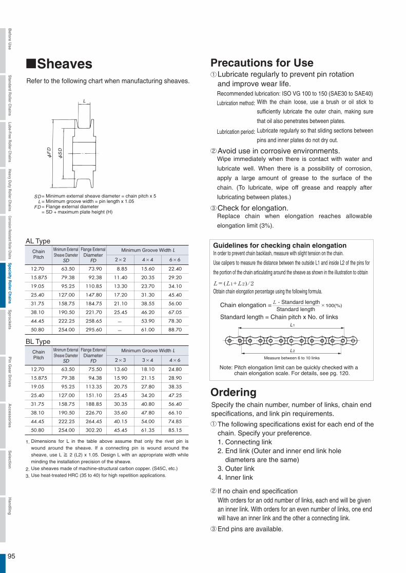
95
L= 1+ 2 )/2L( L
L
2×2 4×4 6×6
12.70 63.50 73.90 8.85 15.60 22.40
15.875 79.38 92.38 11.40 20.35 29.20
19.05 95.25 110.85 13.30 23.70 34.10
25.40 127.00 147.80 17.20 31.30 45.40
31.75 158.75 184.75 21.10 38.55 56.00
38.10 190.50 221.70 25.45 46.20 67.05
44.45 222.25 258.65 53.90 78.30
50.80 254.00 295.60 61.00 88.70
2×3 3×4 4×6
12.70 63.50 75.50 13.60 18.10 24.80
15.875 79.38 94.38 15.90 21.15 28.90
19.05 95.25 113.35 20.75 27.80 38.35
25.40 127.00 151.10 25.45 34.20 47.25
31.75 158.75 188.85 30.35 40.80 56.40
38.10 190.50 226.70 35.60 47.80 66.10
44.45 222.25 264.45 40.15 54.00 74.85
50.80 254.00 302.20 45.45 61.35 85.15
L
L
FD
SD
FD
SD
L1
L2
End pins are available.
SheavesRefer to the following chart when manufacturing sheaves.
= Minimum external sheave diameter = chain pitch x 5= Minimum groove width = pin length x 1.05= Flange external diameter= SD + maximum plate height (H)
ChainPitch
Minimum ExternalSheave Diameter
SD
Flange ExternalDiameter
FD
Minimum Groove Width L
AL Type
BL TypeChainPitch
Minimum ExternalSheave Diameter
SD
Flange ExternalDiameter
FD
Minimum Groove Width L
Precautions for Use
Recommended lubrication: ISO VG 100 to 150 (SAE30 to SAE40)
Lubrication method:
Lubrication period:
Lubricate regularly to prevent pin rotationand improve wear life.
Avoid use in corrosive environments.
Check for elongation.Replace chain when elongation reaches allowable
elongation limit (3%).
Guidelines for checking chain elongation
Note: Pitch elongation limit can be quickly checked with achain elongation scale. For details, see pg. 120.
In order to prevent chain backlash, measure with slight tension on the chain.
Use calipers to measure the distance between the outside L1 and inside L2 of the pins for
the portion of the chain articulating around the sheave as shown in the illustration to obtain
Obtain chain elongation percentage using the following formula.
- Standard lengthStandard length
Chain elongation = ×100(%)
Standard length = Chain pitch x No. of links
Measure between 6 to 10 links
OrderingSpecify the chain number, number of links, chain endspecifications, and link pin requirements.
The following specifications exist for each end of thechain. Specify your preference.1. Connecting link2. End link (Outer and inner end link hole
diameters are the same)3. Outer link4. Inner link
With orders for an odd number of links, each end will be givenan inner link. With orders for an even number of links, one endwill have an inner link and the other a connecting link.
If no chain end specification
With the chain loose, use a brush or oil stick to
sufficiently lubricate the outer chain, making sure
that oil also penetrates between plates.
Lubricate regularly so that sliding sections between
pins and inner plates do not dry out.
1.
2.3.
Dimensions for L in the table above assume that only the rivet pin is wound around the sheave. If a connecting pin is wound around the sheave, use L ≧ 2 (L2) x 1.05. Design L with an appropriate width while minding the installation precision of the sheave.Use sheaves made of machine-structural carbon copper. (S45C, etc.)Use heat-treated HRC (35 to 40) for high repetition applications.
Wipe immediately when there is contact with water and
lubricate well. When there is a possibility of corrosion,
apply a large amount of grease to the surface of the
chain. (To lubricate, wipe off grease and reapply after
lubricating between plates.)
Befo
re Use
Standard R
oller Chains
Lube-Free Roller C
hainsH
eavy Duty R
oller Chains
Corrosion Resistant Roller ChainsS
pecialty Roller C
hainsS
pro
cketsP
in G
ear Drives
Accesso
riesS
election
Han
dlin
g

96
Work load x Usage coefficient (Table 1) x Safety ratio (Table 2) ≦ Minimum tensile strength
4.
1.0
1.3
1.5
2×2、3×42×3、4×4
4×66×6
It is dangerous to use below the safety ratio in Table 2 as it may result in pin rotation and a reduction in strength. In addition, even if the safety ratio in Table 2 is followed, insufficient lubrication may also cause the pins to rotate. Always lubricate the chain regularly.
5.
Selection1. Determine the following based on usage conditions.
Chain speedNumber of repetitions per dayWork load (including inertia and impact strength)When a chain speed of 30 m/min or 1,000 cycles/day isexceeded, Leaf Chains may be inappropriate due to wear. Use an RS Roller Chain.
2. Determine the type of chain.BL Type is recommended.Limit use of AL Type to applications with no impact loador wear considerations (under 100 cycles/day).
3. Determine chain size using the following formula.
Table 1 Usage coefficient
Type of impact
Smooth powertransmission
Slightimpact
Impact
Usagecoefficient
Starts and stops are smooth, and load changes are slight (balance weight suspension, etc.)
Repeated starts and stops, load changes, and reverse operation (forklifts, etc.)
Violent starts and stops, load changes, and reverse operation (mining and construction, etc.)
Table 2 Safety ratio
No. of cycles
Plate combinations
1,000 cycles/day or less
10 cycles/day or less
100 cycles/day or less
8 or more
8 or more
11 or more
9 or more
9 or more
12 or moreAL Type
BL Type
Safety ratio
Applications
Where determining a chain's safety ratio is established by law, select a chain with some leeway using that method and this catalog.
Specialty Roller Chains
Leaf Chains Befo
re Use
Standard R
oller Chains
Lube-Free Roller C
hainsH
eavy Duty R
oller Chains
Corrosion Resistant Roller ChainsS
pecialty Roller C
hainsS
pro
cketsP
in G
ear Drives
Accesso
riesS
election
Han
dlin
g

Pg. 98Pg. 101Pg. 108Pg. 122Pg. 133Pg. 134Pg. 139
97
RS Sprocket Standard Pilot Bore Series (1B, 1C, 2B, 2C, and 1A types)
RS Sprocket Standard Pilot Bore Series (2A type, Single-Dual type)
Fit Bore SeriesLock Series (S/N types)
Corrosion Resistant Series (Stainless Steel, Engineering Plastic, and Fit Bore types)
Specialty SprocketsEasy Bore Finishing ServiceRS Sprocket Engineering Information
RS SprocketLine-up
IndexStarting from pg. 18
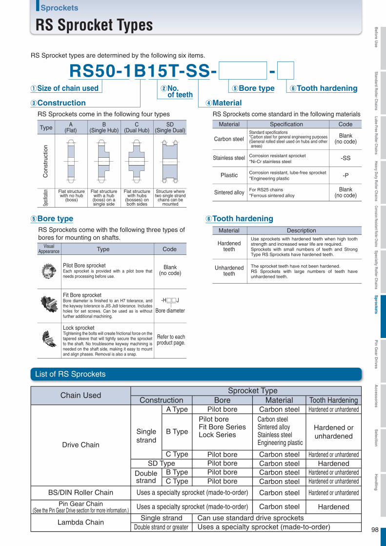
98
Sprockets
RS Sprocket Types
List of RS Sprockets
Type A(Flat)
B(Single Hub)
C(Dual Hub)
SD(Single Dual)
Con
stru
ctio
nSp
ecifica
tion Flat structurewith no hub
(boss)
Flat structurewith a hub(boss) on asingle side
Flat structurewith hubs
(bosses) onboth sides
Structure wheretwo single strand
chains can bemounted
RS Sprockets come in the following four types
RS Sprocket types are determined by the following six items.
VisualAppearance Type Code
RS Sprockets come with the following three types ofbores for mounting on shafts.
⑤Bore type
Carbon steel
Stainless steel
Plastic
Sintered alloy
Material Description
Hardenedteeth
Unhardenedteeth
⑥Tooth hardening
Chain UsedSprocket Type
Construction Bore Material Tooth Hardening
Drive Chain
BS/DIN Roller Chain
Pin Gear Chain(See the Pin Gear Drive section for more information.)
Lambda Chain
A Type
B Type
B Type
C Type
C Type
Pilot borePilot boreFit Bore SeriesLock Series
Pilot borePilot borePilot borePilot bore
Uses a specialty sprocket (made-to-order)
Uses a specialty sprocket (made-to-order)
SD Type
Single strandDouble strand or greater
Singlestrand
Doublestrand
Can use standard drive sprocketsUses a specialty sprocket (made-to-order)
Carbon steel
Carbon steel
Carbon steel
Carbon steelCarbon steelCarbon steelCarbon steel
Carbon steelSintered alloyStainless steelEngineering plastic
Hardened or unhardened
Hardened or unhardenedHardened or unhardened
Hardened or unhardened
Hardened orunhardened
Hardened
Hardened
Pilot Bore sprocketEach sprocket is provided with a pilot bore that needs processing before use.
Fit Bore sprocketBore diameter is finished to an H7 tolerance, and the keyway tolerance is JIS Js9 tolerance. Includes holes for set screws. Can be used as is without further additional machining.
Use sprockets with hardened teeth when high tooth strength and increased wear life are required.Sprockets with small numbers of teeth and Strong Type RS Sprockets have hardened teeth.
The sprocket teeth have not been hardened.RS Sprockets with large numbers of teeth have unhardened teeth.
Lock sprocketTightening the bolts will create frictional force on the tapered sleeve that will tightly secure the sprocket to the shaft. No troublesome keyway machining is needed on the shaft side, making it easy to mount and align phases. Removal is also a snap.
Blank(no code)
-H J
Bore diameter
Refer to eachproduct page.
Material Specification Code
Blank(no code)
Blank(no code)
-SS
-P
④Material③Construction
①Size of chain used ②No. of teeth
⑤Bore type ⑥Tooth hardening
RS Sprockets come standard in the following materials
RS50-1B15T-SS- -
Standard specifications*Carbon steel for general engineering purposes(General rolled steel used on hubs and other areas)
Corrosion resistant sprocket*Ni-Cr stainless steel
Corrosion resistant, lube-free sprocket*Engineering plastic
For RS25 chains*Ferrous sintered alloy
Hardened or unhardened
Befo
re Use
Standard R
oller Chains
Lube-Free Roller C
hainsH
eavy Duty R
oller Chains
Corrosion Resistant Roller ChainsS
pecialty Roller C
hainsS
pro
cketsP
in G
ear Drives
Accesso
riesS
election
Han
dlin
g
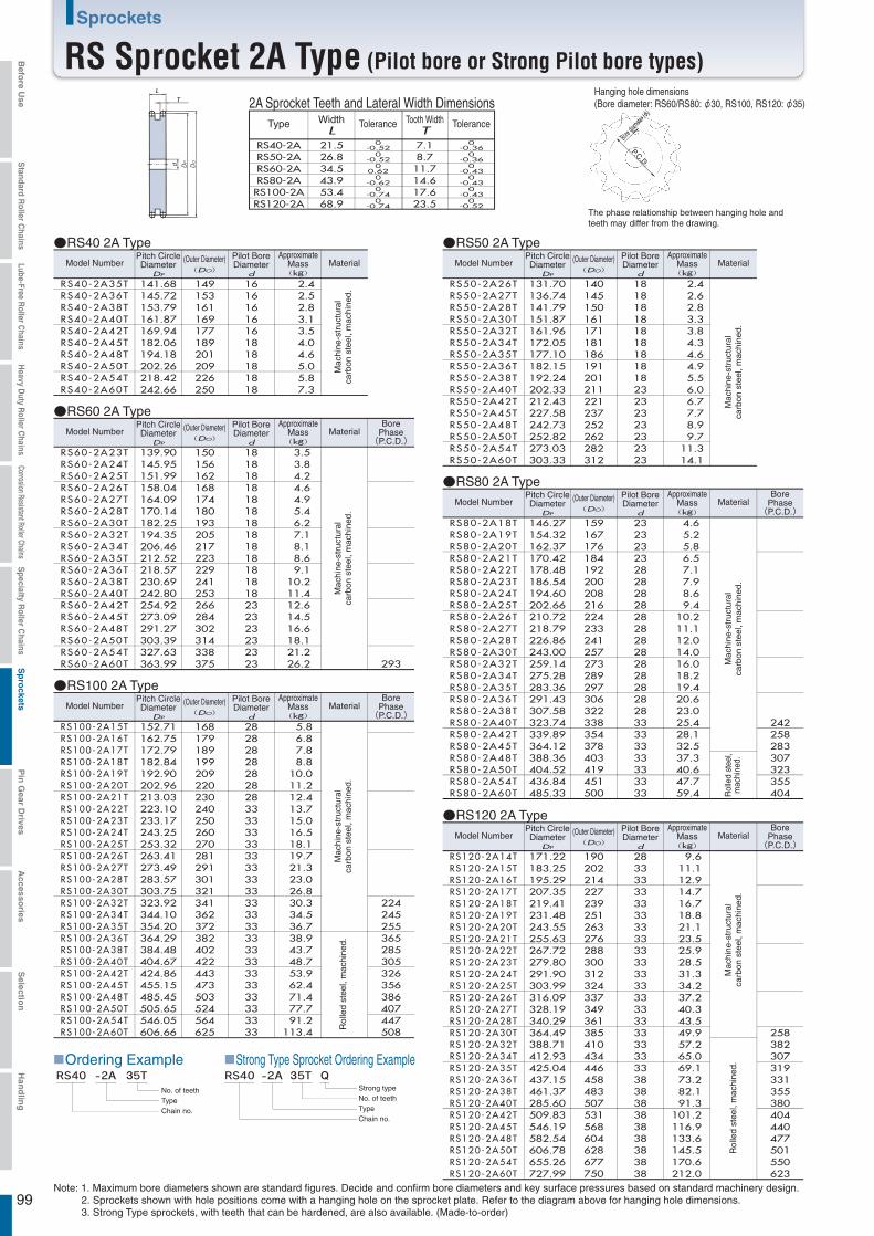
99
Sprockets
RS Sprocket 2A Type (Pilot bore or Strong Pilot bore types)
The phase relationship between hanging hole and teeth may differ from the drawing.
P.C.D.
Bore dia
meter (φ
)
Hanging hole dimensions(Bore diameter: RS60/RS80: φ30, RS100, RS120: φ35)T
L
RS40-2A35TRS40-2A36TRS40-2A38TRS40-2A40TRS40-2A42TRS40-2A45TRS40-2A48TRS40-2A50TRS40-2A54TRS40-2A60T
141.68145.72153.79161.87169.94182.06194.18202.26218.42242.66
149153161169177189201209226250
16161616161818181818
2.42.52.83.13.54.04.65.05.87.3
Model NumberPitch CircleDiameter
DP
(Outer Diameter)(DO)
Pilot BoreDiameter
d
ApproximateMass(kg)
Material
●RS40 2A Type
RS50-2A26TRS50-2A27TRS50-2A28TRS50-2A30TRS50-2A32TRS50-2A34TRS50-2A35TRS50-2A36TRS50-2A38TRS50-2A40TRS50-2A42TRS50-2A45TRS50-2A48TRS50-2A50TRS50-2A54TRS50-2A60T
131.70136.74141.79151.87161.96172.05177.10182.15192.24202.33212.43227.58242.73252.82273.03303.33
140145150161171181186191201211221237252262282312
18181818181818181823232323232323
2.42.62.83.33.84.34.64.95.56.06.77.78.99.7
11.314.1
●RS50 2A Type
RS60-2A23TRS60-2A24TRS60-2A25TRS60-2A26TRS60-2A27TRS60-2A28TRS60-2A30TRS60-2A32TRS60-2A34TRS60-2A35TRS60-2A36TRS60-2A38TRS60-2A40TRS60-2A42TRS60-2A45TRS60-2A48TRS60-2A50TRS60-2A54TRS60-2A60T
139.90145.95151.99158.04164.09170.14182.25194.35206.46212.52218.57230.69242.80254.92273.09291.27303.39327.63363.99
150156162168174180193205217223229241253266284302314338375
18181818181818181818181818232323232323
3.53.84.24.64.95.46.27.18.18.69.1
10.211.412.614.516.618.121.226.2
●RS60 2A Type
Type WidthL
Tolerance Tooth WidthT
Tolerance
RS40-2ARS50-2ARS60-2ARS80-2ARS100-2ARS120-2A
21.526.834.543.953.468.9
0-0.52
0-0.52
00.62
0-0.62
0-0.74
0-0.74
0-0.36
0-0.36
0-0.43
0-0.43
0-0.43
0-0.52
7.18.7
11.714.617.623.5
2A Sprocket Teeth and Lateral Width Dimensions
RS80-2A18TRS80-2A19TRS80-2A20TRS80-2A21TRS80-2A22TRS80-2A23TRS80-2A24TRS80-2A25TRS80-2A26TRS80-2A27TRS80-2A28TRS80-2A30TRS80-2A32TRS80-2A34TRS80-2A35TRS80-2A36TRS80-2A38TRS80-2A40TRS80-2A42TRS80-2A45TRS80-2A48TRS80-2A50TRS80-2A54TRS80-2A60T
146.27154.32162.37170.42178.48186.54194.60202.66210.72218.79226.86243.00259.14275.28283.36291.43307.58323.74339.89364.12388.36404.52436.84485.33
159167176184192200208216224233241257273289297306322338354378403419451500
232323232828282828282828282828282833333333333333
4.65.25.86.57.17.98.69.4
10.211.112.014.016.018.219.420.623.025.428.132.537.340.647.759.4
242258283307323355404
●RS80 2A Type
RS120-2A14TRS120-2A15TRS120-2A16TRS120-2A17TRS120-2A18TRS120-2A19TRS120-2A20TRS120-2A21TRS120-2A22TRS120-2A23TRS120-2A24TRS120-2A25TRS120-2A26TRS120-2A27TRS120-2A28TRS120-2A30TRS120-2A32TRS120-2A34TRS120-2A35TRS120-2A36TRS120-2A38TRS120-2A40TRS120-2A42TRS120-2A45TRS120-2A48TRS120-2A50TRS120-2A54TRS120-2A60T
171.22183.25195.29207.35219.41231.48243.55255.63267.72279.80291.90303.99316.09328.19340.29364.49388.71412.93425.04437.15461.37285.60509.83546.19582.54606.78655.26727.99
190202214227239251263276288300312324337349361385410434446458483507531568604628677750
28333333333333333333333333333333333333383838383838383838
9.611.112.914.716.718.821.123.525.928.531.334.237.240.343.549.957.265.069.173.282.191.3
101.2116.9133.6145.5170.6212.0
258382307319331355380404440477501550623
●RS120 2A Type
RS100-2A15TRS100-2A16TRS100-2A17TRS100-2A18TRS100-2A19TRS100-2A20TRS100-2A21TRS100-2A22TRS100-2A23TRS100-2A24TRS100-2A25TRS100-2A26TRS100-2A27TRS100-2A28TRS100-2A30TRS100-2A32TRS100-2A34TRS100-2A35TRS100-2A36TRS100-2A38TRS100-2A40TRS100-2A42TRS100-2A45TRS100-2A48TRS100-2A50TRS100-2A54TRS100-2A60T
152.71162.75172.79182.84192.90202.96213.03223.10233.17243.25253.32263.41273.49283.57303.75323.92344.10354.20364.29384.48404.67424.86455.15485.45505.65546.05606.66
168179189199209220230240250260270281291301321341362372382402422443473503524564625
282828282828283333333333333333333333333333333333333333
5.86.87.88.8
10.011.212.413.715.016.518.119.721.323.026.830.334.536.738.943.748.753.962.471.477.791.2
113.4
224245255365285305326356386407447508
293
●RS100 2A Type
■Ordering ExampleQ
Strong type
■Strong Type Sprocket Ordering ExampleA 3 A 3
Mac
hine
-str
uctu
ral
carb
on s
teel
, mac
hine
d.M
achi
ne-s
truc
tura
lca
rbon
ste
el, m
achi
ned.
Mac
hine
-str
uctu
ral
carb
on s
teel
, mac
hine
d.M
achi
ne-s
truc
tura
lca
rbon
ste
el, m
achi
ned.
Rol
led
stee
l,m
achi
ned.
Rol
led
stee
l, m
achi
ned.
Mac
hine
-str
uctu
ral
carb
on s
teel
, mac
hine
d.
Mac
hine
-str
uctu
ral
carb
on s
teel
, mac
hine
d.R
olle
d st
eel,
mac
hine
d.
Model NumberPitch CircleDiameter
DP
(Outer Diameter)(DO)
Pilot BoreDiameter
d
ApproximateMass(kg)
BorePhase(P.C.D.)
Material
Model NumberPitch CircleDiameter
DP
(Outer Diameter)(DO)
Pilot BoreDiameter
d
ApproximateMass(kg)
Material
Model NumberPitch CircleDiameter
DP
(Outer Diameter)(DO)
Pilot BoreDiameter
d
ApproximateMass(kg)
Material
Model NumberPitch CircleDiameter
DP
(Outer Diameter)(DO)
Pilot BoreDiameter
d
ApproximateMass(kg)
Material
Model NumberPitch CircleDiameter
DP
(Outer Diameter)(DO)
Pilot BoreDiameter
d
ApproximateMass(kg)
Material
BorePhase(P.C.D.)
BorePhase(P.C.D.)
BorePhase(P.C.D.)
No. of teethTypeChain no.
No. of teethTypeChain no.
Note: 1. Maximum bore diameters shown are standard figures. Decide and confirm bore diameters and key surface pressures based on standard machinery design.2. Sprockets shown with hole positions come with a hanging hole on the sprocket plate. Refer to the diagram above for hanging hole dimensions.3. Strong Type sprockets, with teeth that can be hardened, are also available. (Made-to-order)
Befo
re Use
Standard R
oller Chains
Lube-Free Roller C
hainsH
eavy Duty R
oller Chains
Corrosion Resistant Roller ChainsS
pecialty Roller C
hainsS
pro
cketsP
in G
ear Drives
Accesso
riesS
election
Han
dlin
g
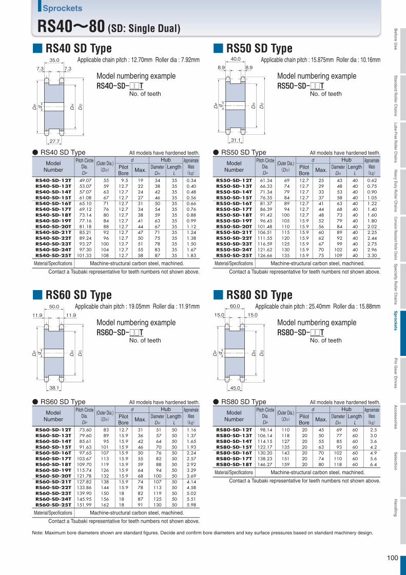
100
Sprockets
RS40~80 (SD: Single Dual)
Applicable chain pitch : 12.70mm Roller dia : 7.92mm■ RS40 SD Type
穴径
穴径 穴径
□□No. of teeth
35.0
7.3 7.3
27.7
50.0
11.9 11.9
38.1
60.0
15.0 15.0
45.0
RS40-SD-12TRS40-SD-13TRS40-SD-14TRS40-SD-15TRS40-SD-16TRS40-SD-17TRS40-SD-18TRS40-SD-19TRS40-SD-20TRS40-SD-21TRS40-SD-22TRS40-SD-23TRS40-SD-24TRS40-SD-25T
49.0753.0757.0761.0865.1069.1273.1477.1681.1885.2189.2493.2797.30
101.33
5559636771768084889296
100104108
9.512.712.712.712.712.712.712.712.712.712.712.712.712.7
1922242731343841444750515558
3438424650545963677175788387
3535353535353535353535353535
0.340.400.480.560.660.760.880.991.121.241.381.501.671.83
RS50-SD-12TRS50-SD-13TRS50-SD-14TRS50-SD-15TRS50-SD-16TRS50-SD-17TRS50-SD-18TRS50-SD-19TRS50-SD-20TRS50-SD-21TRS50-SD-22TRS50-SD-23TRS50-SD-24TRS50-SD-25T
61.3466.3371.3476.3581.3786.3991.4296.45
101.48106.51111.55116.59121.62126.66
697479848994
100105110115120125130135
12.712.712.712.712.712.712.715.915.915.915.915.915.915.9
2529333741444852566062677075
434853586368737984899299
102109
4040404040404040404040404040
0.620.750.901.051.221.401.601.802.022.252.442.752.963.30
40.0
8.9 8.9
31.1
RS60-SD-12TRS60-SD-13TRS60-SD-14TRS60-SD-15TRS60-SD-16TRS60-SD-17TRS60-SD-18TRS60-SD-19TRS60-SD-20TRS60-SD-21TRS60-SD-22TRS60-SD-23TRS60-SD-24TRS60-SD-25T
73.6079.6085.6191.6397.65
103.67109.70115.74121.78127.82133.86139.90145.95151.99
838995
101107113119126132138144150156162
12.715.915.915.915.915.915.915.915.915.915.9181818
3136424650555964687478828791
5157647076828894
100107113119125130
5050505050505050505050505050
1.161.371.651.932.242.572.923.293.694.144.585.025.515.98
RS80-SD-12TRS80-SD-13TRS80-SD-14TRS80-SD-15TRS80-SD-16TRS80-SD-17TRS80-SD-18T
98.14106.14114.15122.17130.20138.23146.27
110118127135143151159
20202020202020
45505563707480
69778593
102110118
60606060606060
2.53.03.64.24.95.66.4
Note: Maximum bore diameters shown are standard figures. Decide and confirm bore diameters and key surface pressures based on standard machinery design.
Model numbering example
Applicable chain pitch : 15.875mm Roller dia : 10.16mm■ RS50 SD Type
□□No. of teeth
Model numbering example
Applicable chain pitch : 19.05mm Roller dia : 11.91mm■ RS60 SD Type
□□No. of teeth
Model numbering example
Applicable chain pitch : 25.40mm Roller dia : 15.88mm■ RS80 SD Type
□□No. of teeth
Model numbering example
ModelNumber
Pitch CircleDia.
(Outer Dia.))
Hub ApproximateMass(kg)
PilotBore
Max. Diameter
Material/Specifications Machine-structural carbon steel, machined.
● RS40 SD Type
Contact a Tsubaki representative for teeth numbers not shown above.
All models have hardened teeth.
Length
ModelNumber
Pitch CircleDia.
(Outer Dia.))
Hub ApproximateMass(kg)
PilotBore
Max. Diameter
Material/Specifications Machine-structural carbon steel, machined.
● RS60 SD Type
Contact a Tsubaki representative for teeth numbers not shown above.
All models have hardened teeth.
LengthModel
Number
Pitch CircleDia.
(Outer Dia.))
Hub ApproximateMass(kg)
PilotBore
Max. Diameter
Material/Specifications Machine-structural carbon steel, machined.
● RS80 SD Type
Contact a Tsubaki representative for teeth numbers not shown above.
All models have hardened teeth.
Length
ModelNumber
Pitch CircleDia.
(Outer Dia.))
Hub ApproximateMass(kg)
PilotBore
Max. Diameter
Material/Specifications Machine-structural carbon steel, machined.
● RS50 SD Type
Contact a Tsubaki representative for teeth numbers not shown above.
All models have hardened teeth.
Length
Befo
re Use
Standard R
oller Chains
Lube-Free Roller C
hainsH
eavy Duty R
oller Chains
Corrosion Resistant Roller ChainsS
pecialty Roller C
hainsS
pro
cketsP
in G
ear Drives
Accesso
riesS
election
Han
dlin
g
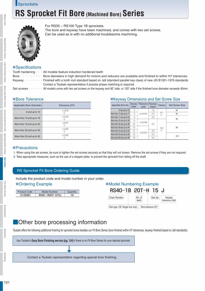
101
Sprockets
RS Sprocket Fit Bore (Machined Bore) Series
Include the product code and model number in your order.
■Ordering Example
Product Code Model Number Quantity
■Model Numbering Example
Chain Number No. ofteeth
Hub type (1B: Single hub only) Bore tolerance (H7)
Keywaytolerance (Js9)
Bore dia.
■SpecificationsAll models feature induction hardened teethBore diameters in high demand for motors and reducers are available and finished to within H7 tolerances.Finished with a tooth root standard based on Js9 (standard parallel key class) of new JIS B1301-1976 standards.Contact a Tsubaki representative if precise phase matching is required.All models come with two set screws on the keyway and 90° side, or 120° side if the finished bore diameter exceeds 40mm.
■Bore ToleranceApplicable Bore Dia. Keyway
WidthTolerance
(Js9)KeywayDepth
Tolerance Set Screw Size
■Keyway Dimensions and Set Screw SizeApplicable Bore Diameter Tolerance (H7)
■Precautions
■Other bore processing informationTsubaki offers the following additional finishing for sprocket bores besides our Fit Bore Series (bore finished within H7 tolerances, keyway finished based on Js9 standards).
Use Tsubaki’s Easy Bore Finishing service (pg. 134) if there is no Fit Bore Series for your desired sprocket.
Contact a Tsubaki representative regarding special bore finishing.
10 and up to 12More than 12 and up to 17More than 17 and up to 22More than 22 and up to 30More than 30 and up to 38More than 38 and up to 44More than 44 and up to 50More than 50 and up to 58More than 58 and up to 65
For RS35 – RS100 Type 1B sprockets.The bore and keyway have been machined, and comes with two set screws.Can be used as is with no additional troublesome machining.
Tooth hardening・・・Bore・・・・・・・・・Keyway・・・・・・・
Set screws・・・・・
6 and up to 10
More than 10 and up to 18
More than 18 and up to 30
More than 30 and up to 50
More than 50 and up to 65
1. When using the set screws, be sure to tighten the set screws securely so that they will not loosen. Remove the set screws if they are not required.2. Take appropriate measures, such as the use of a stopper plate, to prevent the sprocket from falling off the shaft.
RS Sprocket Fit Bore Ordering Guide
Befo
re Use
Standard R
oller Chains
Lube-Free Roller C
hainsH
eavy Duty R
oller Chains
Corrosion Resistant Roller ChainsS
pecialty Roller C
hainsS
pro
cketsP
in G
ear Drives
Accesso
riesS
election
Han
dlin
g
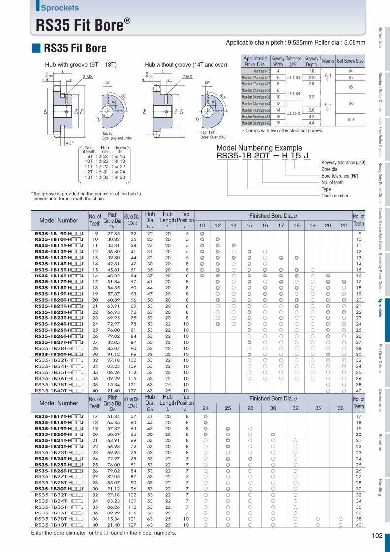
102
Sprockets
RS35 Fit Bore®
■ RS35 Fit Bore
2-MX
90°
KWa4.4
4.8※
0-0.30
KH
2-MX
90°
KWa4.4
0-0.30
KH
RS35-1B 20T - H 15 J 9T : φ 22 :φ: :
1610T : φ 25 :φ 1811T : φ 27 :φ 2212T : φ 31 :φ 2413T : φ 32 :φ 28
ApplicableBore Dia.
KeywayWidth
Tolerance(Js9)
KeywayDepth
Tolerance Set Screw Size
・Comes with two alloy steel set screws.
RS35-1B 9T-H□□□□JRS35-1B10T-H□□□□JRS35-1B11T-H□□□□JRS35-1B12T-H□□□□JRS35-1B13T-H□□□□JRS35-1B14T-H□□□□JRS35-1B15T-H□□□□JRS35-1B16T-H□□□□JRS35-1B17T-H□□□□JRS35-1B18T-H□□□□JRS35-1B19T-H□□□□JRS35-1B20T-H□□□□JRS35-1B21T-H□□□□JRS35-1B22T-H□□□□JRS35-1B23T-H□□□□JRS35-1B24T-H□□□□JRS35-1B25T-H□□□□JRS35-1B26T-H□□□□JRS35-1B27T-H□□□□JRS35-1B28T-H□□JRS35-1B30T-H□□□□JRS35-1B32T-H□□JRS35-1B34T-H□□JRS35-1B35T-H□□JRS35-1B36T-H□□JRS35-1B38T-H□□JRS35-1B40T-H□□J
91011121314151617181920212223242526272830323435363840
27.85 30.82 33.81 36.80 39.80 42.81 45.81 48.82 51.84 54.85 57.87 60.89 63.91 66.93 69.95 72.97 76.00 79.02 82.05 85.07 91.12 97.18
103.23 106.26 109.29 115.34 121.40
323538414447515457606366697275788184879096
102109112115121127
222527313230353741444750535353535353535353535353536363
202020202020202020202020202020222222222222222222222525
5 5 5 5 5 8 8 8 8 8 8 8 8 8 8101010101010101010101010
RS35-1B17T-H□□□□JRS35-1B18T-H□□□□JRS35-1B19T-H□□□□JRS35-1B20T-H□□□□JRS35-1B21T-H□□□□JRS35-1B22T-H□□□□JRS35-1B23T-H□□JRS35-1B24T-H□□□□JRS35-1B25T-H□□□□JRS35-1B26T-H□□□□JRS35-1B27T-H□□JRS35-1B28T-H□□JRS35-1B30T-H□□□□JRS35-1B32T-H□□JRS35-1B34T-H□□JRS35-1B35T-H□□JRS35-1B36T-H□□JRS35-1B38T-H□□JRS35-1B40T-H□□J
17181920212223242526272830323435363840
51.84 54.85 57.87 60.89 63.91 66.93 69.95 72.97 76.00 79.02 82.05 85.07 91.12 97.18
103.23 106.26 109.29 115.34 121.40
57606366697275788184879096
102109112115121127
41444750535353535353535353535353536363
20202020202020222222222222222222222525
8 8 8 8 8 8 8 7 7 7 7 7 7 7 7 7
71010
◎
◎
◎
◎
◎
◎
◎
◎
◎
◎
◎
◎
◎
◎
◎
◎
◎
○
◎
○
○
○
◎
◎
○
◎
○
○
○
○
○
○
○
○
○
○
○
◎
◎
◎
◎
◎
◎
◎
◎
◎
◎
◎
◎
◎
◎
○
◎
○
◎
○
○
○
○
○
○
○
◎
◎
○
◎
◎
◎
○
○
○
○
○
○
○
○
○
○
○
○
○
◎
◎
◎
◎
◎
◎
◎
○
○
◎
○
○
○
○
○
○
○
○
○
○
◎
◎
◎
○
◎
○
◎
◎
○
○
○
○
○
○
○
○
○
○
○
○
○
○
○
○
○
○
○
○
○
○
○
○
○
○
○
○
○
○
○
◎
◎
◎
◎
◎
◎
◎
◎
◎
◎
◎
○
○
◎
○
○
○
○
○
○
◎
○
○
◎
○
◎
○
○
○
○
○
○
○
○
○
○
○
○
○
91011121314151617181920212223242526272830323435363840
◎
◎
◎
◎
○
○
○
○
○
○
○
○
○
○
○
○
○
○
○
◎
◎
◎
◎
○
◎
◎
◎
○
○
◎
○
○
○
○
○
○
○
○
○
○
○
◎
○
○
○
○
○
○
○
○
○
○
○
◎
○
○
○
○
○
○
○
○
○
○
○
○
○
○
○
○
○
○
○
○
○
○
○
○
○
○
○
○
○
○
○
○
○
○
17181920212223242526272830323435363840
Hub with groove (9T – 13T) Hub without groove (14T and over)
Tap: 90°Bore: φ40 and under
Tap: 120°Bore: Over φ40
No.of teeth
Hubdia
Groovedia
*The groove is provided on the perimeter of the hub to prevent interference with the chain.
Applicable chain pitch : 9.525mm Roller dia : 5.08mm
10 and up to 12More than 12 and up to 17More than 17 and up to 22More than 22 and up to 30More than 30 and up to 38More than 38 and up to 44More than 44 and up to 50More than 50 and up to 58More than 58 and up to 65
Model Numbering Example
Keyway tolerance (Js9)Bore dia.Bore tolerance (H7)No. of teethTypeChain number
Model Numbera
No. ofTeeth
No. ofTeeth
PitchCircle Dia.
(Outer Dia.) HubDia.
HubLength
TapPosition
Finished Bore Dia.
Model Numbera
No. ofTeeth
No. ofTeeth
PitchCircle Dia.
(Outer Dia.) HubDia.
HubLength
TapPosition
Finished Bore Dia.
Enter the bore diameter for the found in the model numbers.
Befo
re Use
Standard R
oller Chains
Lube-Free Roller C
hainsH
eavy Duty R
oller Chains
Corrosion Resistant Roller ChainsS
pecialty Roller C
hainsS
pro
cketsP
in G
ear Drives
Accesso
riesS
election
Han
dlin
g
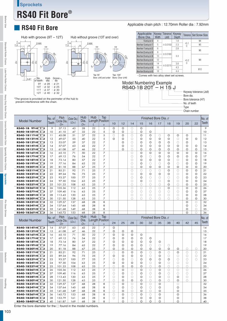
103
Sprockets
RS40 Fit Bore®
2-MX
90°
KWa7.3
5.8※
0-0.36 2-MX
a7.3
0-0.36
KH
90°
KW
KH 120
°
KW
KH
9T : φ 28 :φ 2110T : φ 32 :φ 2511T : φ 37 :φ 3012T : φ 40 :φ 32
RS40-1B 20T - H 15 J
RS40-1B 9T-H□□□□JRS40-1B10T-H□□□□JRS40-1B11T-H□□□□JRS40-1B12T-H□□□□JRS40-1B13T-H□□□□JRS40-1B14T-H□□□□JRS40-1B15T-H□□□□JRS40-1B16T-H□□□□JRS40-1B17T-H□□□□JRS40-1B18T-H□□□□JRS40-1B19T-H□□□□JRS40-1B20T-H□□□□JRS40-1B21T-H□□□□JRS40-1B22T-H□□□□JRS40-1B23T-H□□□□JRS40-1B24T-H□□□□JRS40-1B25T-H□□□□JRS40-1B26T-H□□□□JRS40-1B27T-H□□□□JRS40-1B28T-H□□□□JRS40-1B30T-H□□□□JRS40-1B32T-H□□□□JRS40-1B34T-H□□□□JRS40-1B35T-H□□□□JRS40-1B36T-H□□□□J
9101112131415161718192021222324252627283032343536
37.13 41.10 45.08 49.07 53.07 57.07 61.08 65.10 69.12 73.14 77.16 81.18 85.21 89.24 93.27 97.30
101.33 105.36 109.40 113.43 121.50 129.57 137.64 141.68 145.72
4347515559636771768084889296
100104108112116120128137145149153
28323740374246505457626771757763636363636368686868
22222222222222222222222525252525252525252528282828
5555777777777777777778888
◎
◎
○
◎
◎
◎
◎
◎
◎
◎
◎
○
○
○
○
○
○
○
○
○
○
○
○
○
○
○
○
○
○
○
○
○
◎
◎
◎
◎
◎
◎
◎
◎
◎
◎
◎
◎
○
◎
◎
◎
○
○
○
○
○
◎
◎
◎
◎
◎
◎
◎
○
◎
○
◎
○
◎
○
○
○
○
○
○
○
○
◎
◎
◎
◎
◎
◎
◎
○
◎
○
◎
○
○
○
○
○
○
○
◎
◎
◎
◎
◎
◎
◎
◎
◎
◎
◎
◎
○
◎
◎
◎
○
○
○
◎
○
○
◎
◎
◎
◎
○
○
◎
○
○
○
○
○
○
○
○
○
◎
◎
◎
◎
◎
◎
◎
◎
◎
◎
◎
◎
◎
◎
◎
◎
◎
◎
◎
◎
◎
◎
◎
◎
◎
◎
◎
◎
◎
◎
◎
◎
◎
◎
◎
◎
◎
◎
◎
◎
○
○
○
○
RS40-1B14T-H□□□□JRS40-1B15T-H□□□□JRS40-1B16T-H□□□□JRS40-1B17T-H□□□□JRS40-1B18T-H□□□□JRS40-1B19T-H□□□□JRS40-1B20T-H□□□□JRS40-1B21T-H□□□□JRS40-1B22T-H□□□□JRS40-1B23T-H□□□□JRS40-1B24T-H□□□□JRS40-1B25T-H□□□□JRS40-1B26T-H□□□□JRS40-1B27T-H□□□□JRS40-1B28T-H□□□□JRS40-1B30T-H□□□□JRS40-1B32T-H□□□□JRS40-1B34T-H□□□□JRS40-1B35T-H□□□□JRS40-1B36T-H□□□□JRS40-1B38T-H□□□□JRS40-1B40T-H□□□□J
14151617181920212223242526272830323435363840
14151617181920212223242526272830323435363840
57.07 61.08 65.10 69.12 73.14 77.16 81.18 85.21 89.24 93.27 97.30
101.33 105.36 109.40 113.43 121.50 129.57 137.64 141.68 145.72 153.79 161.87
636771768084889296
100104108112116120128137145149153161169
42465054576267717577636363636363686868686868
22222222222225252525252525252525282828282828
7777777777777777888888
9101112131415161718192021222324252627283032343536
◎
◎
◎
◎
◎
◎
◎
○
◎
○
◎
○
○
○
○
○
○
○
○
○
○
◎
◎
◎
◎
◎
◎
◎
◎
◎
◎
◎
◎
◎
◎
◎
◎
◎
◎
◎
◎
◎
◎
◎
◎
◎
◎
◎
◎
◎
○
◎
◎
○
○
○
◎
○
○
○
○
○
○
◎
◎
◎
◎
◎
◎
◎
◎
◎
◎
◎
◎
◎
◎
◎
◎
◎
◎
◎
◎
◎
◎
○
◎
○
○
◎
○
○
○
○
○
○
○
○
○
○
◎
◎
◎
○
◎
◎
◎
◎
◎
◎
◎
◎
◎
◎
◎
◎
◎
◎
◎
◎
○
◎
○
○
◎
○
○
○
○
○
○
◎
◎
○
○
○
○
○
○
◎
◎
○
◎
◎
◎
◎
◎
○
○
○
○
○
○
○
○
○
○
○
○
○
○
■ RS40 Fit Bore
: :
ApplicableBore Dia.
KeywayWidth
Tolerance(Js9)
KeywayDepth
Tolerance Set Screw Size
・Comes with two alloy steel set screws.
Hub with groove (9T – 12T) Hub without groove (13T and over)
Tap: 90°Bore: φ40 and under
Tap: 120°Bore: Over φ40No.
of teethHubdia
Groovedia
*The groove is provided on the perimeter of the hub to prevent interference with the chain.
Applicable chain pitch : 12.70mm Roller dia : 7.92mm
10 and up to 12More than 12 and up to 17More than 17 and up to 22More than 22 and up to 30More than 30 and up to 38More than 38 and up to 44More than 44 and up to 50More than 50 and up to 58More than 58 and up to 65
Model Numbering Example
Keyway tolerance (Js9)Bore dia.Bore tolerance (H7)No. of teethTypeChain number
Model Numbera
No. ofTeeth
No. ofTeeth
PitchCircle Dia.
(Outer Dia.) HubDia.
HubLength
TapPosition
Finished Bore Dia.
Model Numbera
No. ofTeeth
No. ofTeeth
PitchCircle Dia.
(Outer Dia.) HubDia.
HubLength
TapPosition
Finished Bore Dia.
Enter the bore diameter for the found in the model numbers.
Befo
re Use
Standard R
oller Chains
Lube-Free Roller C
hainsH
eavy Duty R
oller Chains
Corrosion Resistant Roller ChainsS
pecialty Roller C
hainsS
pro
cketsP
in G
ear Drives
Accesso
riesS
election
Han
dlin
g
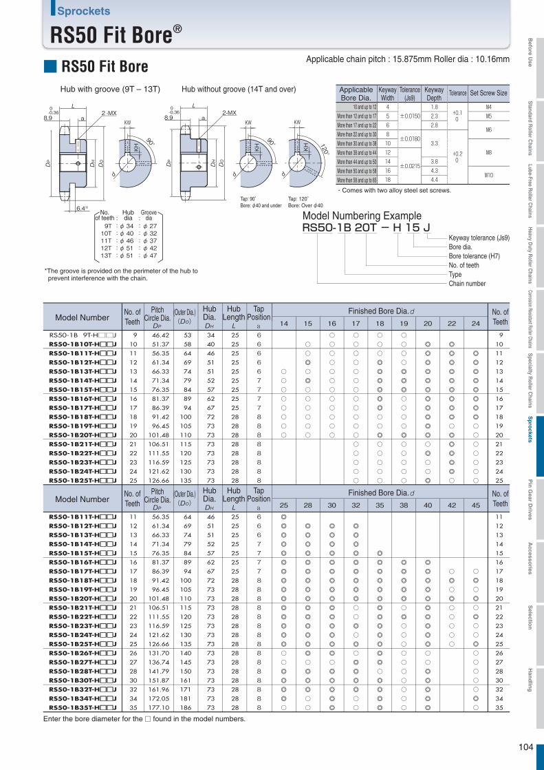
104
Sprockets
RS50 Fit Bore®
■ RS50 Fit Bore
: :
Hub with groove (9T – 13T) Hub without groove (14T and over)
Tap: 90°Bore: φ40 and under
Tap: 120°Bore: Over φ40
No.of teeth
Hubdia
Groovedia
Applicable chain pitch : 15.875mm Roller dia : 10.16mm
Model Numbering Example
2-MXa8.9
0-0.36
120°
KW
KH
2-MX
90°
KWa8.9
6.4※
0-0.36
KH
90°
KW
KH
9T : φ 34 :φ 2710T : φ 40 :φ 3211T : φ 46 :φ 3712T : φ 51 :φ 4213T : φ 51 :φ 47
RS50-1B 20T - H 15 J
○
○
○
○
○
○
○
○
○
○
◎◎
○
◎
○
○
○
○
○
○
○
○
○
○
○
○
○
○
○
○
○
○
○
○
○
○
○
○
○
○
○
○
○
○
○
○
○
○
○
○
○
○
◎
◎
◎
◎
◎
◎
○
○
◎
○
○
○
○
○
○
○
○
○
◎
◎
◎
○
○
○
○
◎
○
○
○
○
○
◎
◎
◎
◎
◎
◎
◎
◎
◎
◎
◎
○
◎
○
○
◎
◎
◎
◎
◎
◎
◎
◎
◎
◎
○
◎
◎
◎
◎
◎
○
◎
◎
◎
◎
◎
◎
◎
◎
○
○
○
○
○
○
○
RS50-1B 9T-H□□J
RS50-1B10T-H□□□□JRS50-1B11T-H□□□□JRS50-1B12T-H□□□□JRS50-1B13T-H□□□□JRS50-1B14T-H□□□□JRS50-1B15T-H□□□□JRS50-1B16T-H□□□□JRS50-1B17T-H□□□□JRS50-1B18T-H□□□□JRS50-1B19T-H□□□□JRS50-1B20T-H□□□□JRS50-1B21T-H□□□□JRS50-1B22T-H□□□□JRS50-1B23T-H□□□□JRS50-1B24T-H□□□□JRS50-1B25T-H□□□□J
9
10
11
12
13
14
15
16
17
18
19
20
21
22
23
24
25
9
10
11
12
13
14
15
16
17
18
19
20
21
22
23
24
25
46.42
51.37
56.35
61.34
66.33
71.34
76.35
81.37
86.39
91.42
96.45
101.48
106.51
111.55
116.59
121.62
126.66
53
58
64
69
74
79
84
89
94
100
105
110
115
120
125
130
135
34
40
46
51
51
52
57
62
67
72
73
73
73
73
73
73
73
25
25
25
25
25
25
25
25
25
28
28
28
28
28
28
28
28
66666777788888888
◎
◎
◎
◎
◎
◎
◎
◎
◎
◎
◎
◎
◎
◎
◎
○
○
◎
◎
◎
◎
○
◎
◎
◎
◎
◎
◎
◎
◎
◎
◎
◎
◎
◎
◎
◎
○
◎
◎
◎
○
○
◎
◎
◎
◎
◎
◎
◎
◎
◎
◎
◎
◎
◎
◎
◎
○
◎
◎
◎
◎
◎
◎
◎
◎
◎
◎
◎
◎
◎
◎
○
○
◎
○
◎
○
◎
◎
◎
◎
○
○
◎
◎
◎
◎
◎
◎
◎
◎
◎
◎
◎
◎
◎
○
◎
◎
◎
◎
◎
◎
◎
◎
◎
○
◎
○
○
○
○
○
○
○
○
○
○
◎
◎
◎
◎
◎
◎
◎
◎
◎
◎
○
○
◎
◎
◎
◎
◎
○
◎
○
◎
○
○
○
○
○
○
◎
○
◎
○
◎
○
○
◎
○
○
○
○
○
◎
○
RS50-1B11T-H□□□□JRS50-1B12T-H□□□□JRS50-1B13T-H□□□□JRS50-1B14T-H□□□□JRS50-1B15T-H□□□□JRS50-1B16T-H□□□□JRS50-1B17T-H□□□□JRS50-1B18T-H□□□□JRS50-1B19T-H□□□□JRS50-1B20T-H□□□□JRS50-1B21T-H□□□□JRS50-1B22T-H□□□□JRS50-1B23T-H□□□□JRS50-1B24T-H□□□□JRS50-1B25T-H□□□□JRS50-1B26T-H□□□□JRS50-1B27T-H□□□□JRS50-1B28T-H□□□□JRS50-1B30T-H□□□□JRS50-1B32T-H□□□□JRS50-1B34T-H□□□□JRS50-1B35T-H□□□□J
11
12
13
14
15
16
17
18
19
20
21
22
23
24
25
26
27
28
30
32
34
35
11
12
13
14
15
16
17
18
19
20
21
22
23
24
25
26
27
28
30
32
34
35
56.35
61.34
66.33
71.34
76.35
81.37
86.39
91.42
96.45
101.48
106.51
111.55
116.59
121.62
126.66
131.70
136.74
141.79
151.87
161.96
172.05
177.10
64
69
74
79
84
89
94
100
105
110
115
120
125
130
135
140
145
150
161
171
181
186
46
51
51
52
57
62
67
72
73
73
73
73
73
73
73
73
73
73
73
73
73
73
25
25
25
25
25
25
25
28
28
28
28
28
28
28
28
28
28
28
28
28
28
28
6667777888888888888888
ApplicableBore Dia.
KeywayWidth
Tolerance(Js9)
KeywayDepth
Tolerance Set Screw Size
・Comes with two alloy steel set screws.
10 and up to 12More than 12 and up to 17More than 17 and up to 22More than 22 and up to 30More than 30 and up to 38More than 38 and up to 44More than 44 and up to 50More than 50 and up to 58More than 58 and up to 65
Keyway tolerance (Js9)Bore dia.Bore tolerance (H7)No. of teethTypeChain number
*The groove is provided on the perimeter of the hub to prevent interference with the chain.
Model Numbera
No. ofTeeth
No. ofTeeth
PitchCircle Dia.
(Outer Dia.) HubDia.
HubLength
TapPosition
Finished Bore Dia.
Model Numbera
No. ofTeeth
No. ofTeeth
PitchCircle Dia.
(Outer Dia.) HubDia.
HubLength
TapPosition
Finished Bore Dia.
Enter the bore diameter for the found in the model numbers.
Befo
re Use
Standard R
oller Chains
Lube-Free Roller C
hainsH
eavy Duty R
oller Chains
Corrosion Resistant Roller ChainsS
pecialty Roller C
hainsS
pro
cketsP
in G
ear Drives
Accesso
riesS
election
Han
dlin
g
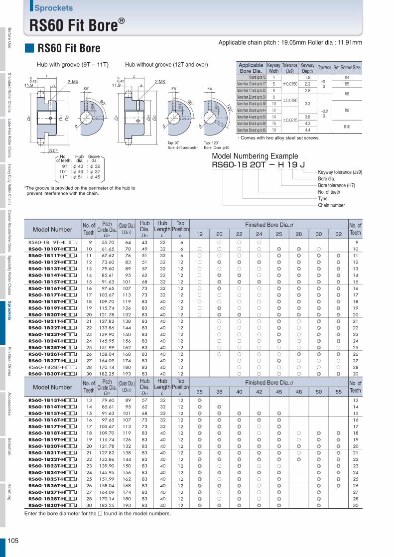
2-MXa11.9
0-0.43
120°
KW
KH
2-MX
90°
KWa11.9
8.0※
0-0.43
KH
90°
KW
KH
9T : φ 43 :φ 3210T : φ 49 :φ 3711T : φ 51 :φ 45
RS60-1B 20T - H 19 J
RS60-1B 9T-H□□J
RS60-1B10T-H□□□□JRS60-1B11T-H□□□□JRS60-1B12T-H□□□□JRS60-1B13T-H□□□□JRS60-1B14T-H□□□□JRS60-1B15T-H□□□□JRS60-1B16T-H□□□□JRS60-1B17T-H□□□□JRS60-1B18T-H□□□□JRS60-1B19T-H□□□□JRS60-1B20T-H□□□□JRS60-1B21T-H□□□□JRS60-1B22T-H□□□□JRS60-1B23T-H□□□□JRS60-1B24T-H□□□□JRS60-1B25T-H□□□□JRS60-1B26T-H□□□□JRS60-1B27T-H□□□□JRS60-1B28T-H□□J
RS60-1B30T-H□□□□J
9
10
11
12
13
14
15
16
17
18
19
20
21
22
23
24
25
26
27
28
30
55.70
61.65
67.62
73.60
79.60
85.61
91.63
97.65
103.67
109.70
115.74
121.78
127.82
133.86
139.90
145.95
151.99
158.04
164.09
170.14
182.25
64
70
76
83
89
95
101
107
113
119
126
132
138
144
150
156
162
168
174
180
193
43
49
51
51
57
62
68
73
73
83
83
83
83
83
83
83
83
83
83
83
83
32
32
32
32
32
32
32
32
32
40
40
40
40
40
40
40
40
40
40
40
40
6
6
6
12
12
12
12
12
12
12
12
12
12
12
12
12
12
12
12
12
12
○
○
○
○
○
○
○
○
○
○
○
◎
◎
◎
◎
◎
◎
◎
◎
◎
◎
◎
◎
◎
◎
◎
◎
◎
○
○
○
◎
○
◎
◎
◎
○
○
◎
◎
○
○
○
○
○
○
◎
◎
◎
◎
◎
◎
◎
◎
◎
○
◎
○
◎
○
○
◎
○
○
○
◎
○
◎
◎
○
○
○
○
◎
○
○
○
○
○
○
○
○
○
◎
◎
◎
◎
◎
◎
◎
◎
◎
◎
◎
◎
◎
◎
◎
○
○
○
◎
○
○
◎
○
○
○
○
○
○
○
○
○
○
○
○
○
○
◎
◎
○
○
◎
◎
◎
◎
○
◎
○
○
○
○
◎
◎
◎
◎
◎
◎
◎
◎
◎
◎
◎
◎
◎
◎
◎
◎
○
○
◎
○
○
◎
◎
◎
◎
◎
◎
◎
◎
○
◎
◎
◎
◎
◎
◎
◎
◎
◎
◎
◎
◎
◎
◎
◎
◎
◎
○
○
○
○
○
◎
○
○
○
○
○
◎
○
◎
○
◎
◎
◎
◎
◎
◎
◎
◎
◎
◎
◎
◎
◎
◎
◎
◎
○
○
◎
◎
◎
◎
◎
◎
◎
◎
◎
◎
◎
◎
◎
◎
◎
◎
◎
◎
◎
◎
◎
◎
◎
◎
◎
◎
◎
○
◎
○
○
◎
◎
◎
◎
◎
◎
◎
◎
◎
◎
12
12
12
12
12
12
12
12
12
12
12
12
12
12
12
12
12
32
32
32
32
32
40
40
40
40
40
40
40
40
40
40
40
40
57
62
68
73
73
83
83
83
83
83
83
83
83
83
83
83
83
89
95
101
107
113
119
126
132
138
144
150
156
162
168
174
180
193
79.60
85.61
91.63
97.65
103.67
109.70
115.74
121.78
127.82
133.86
139.90
145.95
151.99
158.04
164.09
170.14
182.25
13
14
15
16
17
18
19
20
21
22
23
24
25
26
27
28
30
9
10
11
12
13
14
15
16
17
18
19
20
21
22
23
24
25
26
27
28
30
13
14
15
16
17
18
19
20
21
22
23
24
25
26
27
28
30
RS60-1B13T-H□□□□JRS60-1B14T-H□□□□JRS60-1B15T-H□□□□JRS60-1B16T-H□□□□JRS60-1B17T-H□□□□JRS60-1B18T-H□□□□JRS60-1B19T-H□□□□JRS60-1B20T-H□□□□JRS60-1B21T-H□□□□JRS60-1B22T-H□□□□JRS60-1B23T-H□□□□JRS60-1B24T-H□□□□JRS60-1B25T-H□□□□JRS60-1B26T-H□□□□JRS60-1B27T-H□□□□JRS60-1B28T-H□□□□JRS60-1B30T-H□□□□J
105
Sprockets
RS60 Fit Bore®
■ RS60 Fit Bore
: :
ApplicableBore Dia.
KeywayWidth
Tolerance(Js9)
KeywayDepth
Tolerance Set Screw Size
・Comes with two alloy steel set screws.
Hub with groove (9T – 11T) Hub without groove (12T and over)
Tap: 90°Bore: φ40 and under
Tap: 120°Bore: Over φ40
No.of teeth
Hubdia
Groovedia
*The groove is provided on the perimeter of the hub to prevent interference with the chain.
Applicable chain pitch : 19.05mm Roller dia : 11.91mm
10 and up to 12More than 12 and up to 17More than 17 and up to 22More than 22 and up to 30More than 30 and up to 38More than 38 and up to 44More than 44 and up to 50More than 50 and up to 58More than 58 and up to 65
Model Numbering Example
Keyway tolerance (Js9)Bore dia.Bore tolerance (H7)No. of teethTypeChain number
Model Numbera
No. ofTeeth
No. ofTeeth
PitchCircle Dia.
(Outer Dia.) HubDia.
HubLength
TapPosition
Finished Bore Dia.
Model Numbera
No. ofTeeth
No. ofTeeth
PitchCircle Dia.
(Outer Dia.) HubDia.
HubLength
TapPosition
Finished Bore Dia.
Enter the bore diameter for the found in the model numbers.
Befo
re Use
Standard R
oller Chains
Lube-Free Roller C
hainsH
eavy Duty R
oller Chains
Corrosion Resistant Roller ChainsS
pecialty Roller C
hainsS
pro
cketsP
in G
ear Drives
Accesso
riesS
election
Han
dlin
g

2-MXa15.0
0-0.43
120°
KW
KH
2-MX
90°
KWa15.0
10.4※
0-0.43
KH
90°
KW
KH
9T : φ 58 :φ 44RS80-1B 20T - H 25 J
RS80-1B 9T-H□□□□JRS80-1B10T-H□□□□JRS80-1B11T-H□□□□JRS80-1B12T-H□□□□JRS80-1B13T-H□□□□JRS80-1B14T-H□□□□JRS80-1B15T-H□□□□JRS80-1B16T-H□□□□JRS80-1B17T-H□□□□JRS80-1B18T-H□□□□JRS80-1B19T-H□□□□JRS80-1B20T-H□□□□JRS80-1B21T-H□□J
9
10
11
12
13
14
15
16
17
18
19
20
21
9
10
11
12
13
14
15
16
17
18
19
20
21
74.26
82.20
90.16
98.14
106.14
114.15
122.17
130.20
138.23
146.27
154.32
162.37
170.42
85
93
102
110
118
127
135
143
151
159
167
176
184
58
52
60
67
77
77
93
93
93
93
93
93
93
40
40
40
40
40
40
40
40
40
40
40
40
40
8
12
12
12
12
12
12
12
12
12
12
12
12
◎
◎
◎
◎
◎
◎
◎
◎
◎
◎
○
◎
○
○
○
○
○
○
○
○
○
○
○
◎
◎
◎
◎
◎
◎
◎
○
◎
○
○
○
○
○
○
○
◎
○
○
○
○
○
○
◎
◎
◎
◎
◎
◎
◎
◎
◎
◎
○
◎
◎
◎
◎
◎
◎
◎
◎
◎
○
◎
○
◎
◎
◎
◎
◎
◎
○
◎
○
◎
◎
◎
◎
○
◎
◎
○
◎
◎
○
○
○
◎
◎
◎
◎
◎
◎
◎
◎
◎
◎
◎
◎
◎
◎
◎
◎
◎
◎
○
◎
○
◎
◎
◎
◎
◎
◎
◎
◎
◎
◎
◎
◎
◎
◎
◎
◎
◎
○
◎
◎
◎
◎
◎
◎
◎
RS80-1B12T-H□□□□JRS80-1B13T-H□□□□JRS80-1B14T-H□□□□JRS80-1B15T-H□□□□JRS80-1B16T-H□□□□JRS80-1B17T-H□□□□JRS80-1B18T-H□□□□JRS80-1B19T-H□□□□JRS80-1B20T-H□□□□JRS80-1B21T-H□□□□J
12
13
14
15
16
17
18
19
20
21
12
13
14
15
16
17
18
19
20
21
98.14
106.14
114.15
122.17
130.20
138.23
146.27
154.32
162.37
170.42
110
118
127
135
143
151
159
167
176
184
40
40
40
40
40
40
40
40
40
40
12
12
12
12
12
12
12
12
12
12
106
Sprockets
RS80 Fit Bore®
■ RS80 Fit Bore
: :
Hub with groove (9T) Hub without groove (10T and over)
Tap: 90°Bore: φ40 and under
Tap: 120°Bore: Over φ40
No.of teeth
Hubdia
Groovedia
Applicable chain pitch : 25.40mm Roller dia : 15.88mm
Model Numbering Example
ApplicableBore Dia.
KeywayWidth
Tolerance(Js9)
KeywayDepth
Tolerance Set Screw Size
・Comes with two alloy steel set screws.
10 and up to 12More than 12 and up to 17More than 17 and up to 22More than 22 and up to 30More than 30 and up to 38More than 38 and up to 44More than 44 and up to 50More than 50 and up to 58More than 58 and up to 65
Keyway tolerance (Js9)Bore dia.Bore tolerance (H7)No. of teethTypeChain number
*The groove is provided on the perimeter of the hub to prevent interference with the chain.
Model Numbera
No. ofTeeth
No. ofTeeth
PitchCircle Dia.
(Outer Dia.) HubDia.
HubLength
TapPosition
Finished Bore Dia.
Model Numbera
No. ofTeeth
No. ofTeeth
PitchCircle Dia.
(Outer Dia.) HubDia.
HubLength
TapPosition
Finished Bore Dia.
Enter the bore diameter for the found in the model numbers.
Befo
re Use
Standard R
oller Chains
Lube-Free Roller C
hainsH
eavy Duty R
oller Chains
Corrosion Resistant Roller ChainsS
pecialty Roller C
hainsS
pro
cketsP
in G
ear Drives
Accesso
riesS
election
Han
dlin
g

2-MXa18.0
0-0.43
120°
KW
KH
2-MXa18.0
0-0.43
90°
KWKH
RS100-1B 20T - H 38 J
○
○
○
○
○
○
○
○
○
○
○
○
○
○
○
○
○
○
○
○
○
○
○
○
○
○
○
○
○
○
○
○
○
○
○
○
○
○
○
○
○
○
○
○
○
○
○
○
○
○
◎◎
◎
○
◎
◎
○
◎
○
○
○
○
○
◎
○
○
◎
◎
◎
◎
◎
◎
○
○
○
◎
○
○
○
○
○
○
○
◎
◎
◎
◎
◎
◎
◎
RS100-1B10T-H□□J
RS100-1B11T-H□□J
RS100-1B12T-H□□□□JRS100-1B13T-H□□□□JRS100-1B14T-H□□J
RS100-1B15T-H□□□□JRS100-1B16T-H□□J
RS100-1B17T-H□□J
RS100-1B18T-H□□J
RS100-1B19T-H□□J
RS100-1B20T-H□□J
10
11
12
13
14
15
16
17
18
19
20
102.75
112.70
122.67
132.67
142.68
152.71
162.75
172.79
182.84
192.90
202.96
117
127
138
148
158
168
179
189
199
209
220
65
75
86
88
88
98
98
107
107
107
107
50
50
50
50
50
50
50
50
50
50
50
15
15
15
15
15
15
15
15
15
15
15
RS100-1B10T-H□□J
RS100-1B11T-H□□J
RS100-1B12T-H□□□□JRS100-1B13T-H□□□□JRS100-1B14T-H□□□□JRS100-1B15T-H□□□□JRS100-1B16T-H□□□□JRS100-1B17T-H□□□□JRS100-1B18T-H□□□□JRS100-1B19T-H□□□□JRS100-1B20T-H□□□□JRS100-1B21T-H□□□□J
10
11
12
13
14
15
16
17
18
19
20
21
10
11
12
13
14
15
16
17
18
19
20
10
11
12
13
14
15
16
17
18
19
20
21
102.75
112.70
122.67
132.67
142.68
152.71
162.75
172.79
182.84
192.90
202.96
213.03
117
127
138
148
158
168
179
189
199
209
220
230
65
75
86
88
88
98
98
107
107
107
107
107
50
50
50
50
50
50
50
50
50
50
50
50
15
15
15
15
15
15
15
15
15
15
15
15
107
Sprockets
RS100 Fit Bore®
■ RS100 Fit BoreApplicableBore Dia.
KeywayWidth
Tolerance(Js9)
KeywayDepth
Tolerance Set Screw Size
・Comes with two alloy steel set screws.Tap: 90°Bore: φ40 and under
Tap: 120°Bore: Over φ40
Applicable chain pitch : 31.75mm Roller dia : 19.05mm
10 and up to 12More than 12 and up to 17More than 17 and up to 22More than 22 and up to 30More than 30 and up to 38More than 38 and up to 44More than 44 and up to 50More than 50 and up to 58More than 58 and up to 65
Model Numbering Example
Keyway tolerance (Js9)Bore dia.Bore tolerance (H7)No. of teethTypeChain number
Model Numbera
No. ofTeeth
No. ofTeeth
PitchCircle Dia.
(Outer Dia.) HubDia.
HubLength
TapPosition
Finished Bore Dia.
Model Numbera
No. ofTeeth
No. ofTeeth
PitchCircle Dia.
(Outer Dia.) HubDia.
HubLength
TapPosition
Finished Bore Dia.
Enter the bore diameter for the found in the model numbers.
Befo
re Use
Standard R
oller Chains
Lube-Free Roller C
hainsH
eavy Duty R
oller Chains
Corrosion Resistant Roller ChainsS
pecialty Roller C
hainsS
pro
cketsP
in G
ear Drives
Accesso
riesS
election
Han
dlin
g
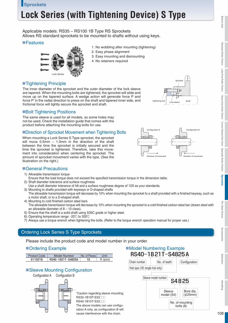
108
Sprockets
Lock Series (with Tightening Device) S Type
■Features
■Tightening Principle
■Bolt Tightening Positions
■Direction of Sprocket Movement when Tightening Bolts
■General Precautions
Please include the product code and model number in your order.
■Ordering Example
Product Code Model Number No. of Pieces Unit
■Model Numbering Example
■Sleeve Mounting ConfigurationConfiguration A Configuration B
Configuration A
Direction of movement Direction of movement
Configuration B
When mounting a Lock Series S Type sprocket, the sprocket will move 0.5mm – 1.0mm in the direction of the shaft between the time the sprocket is initially secured and the time the sprocket is tightened. Therefore, take this move-ment into consideration when centering the sprocket. The amount of sprocket movement varies with the type. (See the illustration on the right.)
Allowable transmission torqueEnsure that the load torque does not exceed the specified transmission torque in the dimension table.Shaft diameter tolerance and surface roughnessUse a shaft diameter tolerance of h8 and a surface roughness degree of 12S as your standards.Mounting to shafts provided with keyways or D-shaped shaftsThe allowable transmission torque will decrease by 10% when mounting the sprocket to a shaft provided with a finished keyway, such as a motor shaft, or to a D-shaped shaft.Mounting to cold finished carbon steel barsThe allowable transmission torque will decrease by 10% when mounting the sprocket to a cold finished carbon steel bar (drawn steel with an allowable diameter of 8 – 10 class).Ensure that the shaft is a solid shaft using S35C grade or higher steel.Operating temperature range: -20℃ to 200℃Always use a torque wrench when tightening the bolts. (Refer to the torque wrench operation manual for proper use.)
1)
2)
3)
4)
5)6)7)
Applicable models: RS35 – RS100 1B Type RS SprocketsAllows RS standard sprockets to be mounted to shafts without using keys.
Lock Series
1. No wobbling after mounting (tightening)2. Easy phase alignment3. Easy mounting and dismounting4. No retainers required
The inner diameter of the sprocket and the outer diameter of the lock sleeve are tapered. When the mounting bolts are tightened, the sprocket will slide and move up on the tapered surface. A wedge action will generate force P and force P’ in the radial direction to press on the shaft and tapered inner side, and frictional force will tightly secure the sprocket and shaft.
The same sleeve is used for all models, so some holes may not be used. Check the installation guide that comes with the product before attaching the mounting bolts for use.
Sprocket
Tightening boltLock sleeve Shaft
Ordering Lock Series S Type Sprockets
K (pcs)
*Caution regarding sleeve mounting:RS35-1B19T-S33□□□RS40-1B15T-S33□□□The above models can use configu-ration A only, as configuration B will cause interference with the chain.
Chain number
Hub type (1B: single hub only)
No. of teeth Configuration
Sleeve model number
Sleevemodel (S4)
No. of mountingbolts (8)
Bore dia.(φ25mm)
Befo
re Use
Standard R
oller Chains
Lube-Free Roller C
hainsH
eavy Duty R
oller Chains
Corrosion Resistant Roller ChainsS
pecialty Roller C
hainsS
pro
cketsP
in G
ear Drives
Accesso
riesS
election
Han
dlin
g
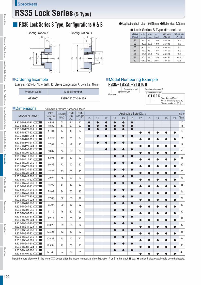
109
Sprockets
RS35 Lock Series (S Type)
■ RS35 Lock Series S Type, Configurations A & B
4.4
Sleeve
Model
φmm
φmm mm
Bolt Size
(M x S)
Tightening Torque
(N・m)
32.0 24.0 12.0 M4×16 4.2
42.0 32.0 14.0 M5×18 8.3
48.0 38.5 15.5 M5×20 8.3
56.0 46.0 15.5 M5×20 8.3
66.0 56.0 17.5 M5×22 8.3
80.0 68.0 21.0 M6×25 16.8
101.0 86.0 24.5 M8×30 40.5
■ Lock Series S Type dimensions
■Dimensions
16
Configuration B
10 11 12 14 15 16 17 18 19 20 22
RS35-1B15T-S14□□■RS35-1B16T-S14□□■RS35-1B17T-S14□□■RS35-1B17T-S24□□■RS35-1B18T-S14□□■RS35-1B18T-S24□□■RS35-1B19T-S14□□■RS35-1B19T-S24□□■RS35-1B20T-S14□□■RS35-1B20T-S24□□■RS35-1B21T-S16□□■RS35-1B21T-S24□□■RS35-1B22T-S16□□■RS35-1B22T-S24□□■RS35-1B23T-S16□□■RS35-1B23T-S24□□■RS35-1B24T-S16□□■RS35-1B24T-S24□□■RS35-1B25T-S16□□■RS35-1B25T-S24□□■RS35-1B26T-S16□□■RS35-1B26T-S24□□■RS35-1B27T-S16□□■RS35-1B27T-S24□□■RS35-1B28T-S16□□■RS35-1B28T-S24□□■RS35-1B30T-S16□□■RS35-1B30T-S24□□■RS35-1B32T-S16□□■RS35-1B32T-S24□□■RS35-1B34T-S16□□■RS35-1B34T-S24□□■RS35-1B35T-S16□□■RS35-1B35T-S24□□■RS35-1B36T-S16□□■RS35-1B36T-S24□□■RS35-1B38T-S16□□■RS35-1B38T-S24□□■RS35-1B40T-S16□□■RS35-1B40T-S24□□■
45.8148.82
51.84
54.85
57.87
60.89
63.91
66.93
69.95
72.97
76.00
79.02
82.05
85.07
91.12
97.18
103.23
106.26
109.29
115.34
121.40
5154
57
60
63
66
69
72
75
78
81
84
87
90
96
102
109
112
115
121
127
2020
20
20
20
20
20
20
20
20
20
22
22
22
22
22
22
22
22
25
25
●
●
●
●
●
●
●
●
●
●
●
●
●
●
●
●
●
●
●
●
●
●
●
●
●
●
●
●
●
●
●
●
●
●
●
●
●
●
●
●
●
●
●
●
●
●
●
●
●
●
●
●
●
●
●
●
●
●
●
●
●
●
●
●
●
●
●
●
●
●
●
●
●
●
●
●
●●●
●
●
●
●
●
●
●
●
●
●
●
●
●
●
●
●
●
●
●
●
●
●●●
●●●
●
●
●
●●●
●
●
●
●
●
●
●
●
●
●
●
●
●
●
●
●
●
●
●●●
●
●
●
●
●
●
●
●
●
●
●
●
●
●
●
●
●
●
●●●
●
●
●
●
●
●
●
●
●
●
●
●
●
●
●
●
●
●
3537
41
44
47
50
53
53
53
53
53
53
53
53
53
53
53
53
53
63
63
1516
17
18
19
20
21
22
23
24
25
26
27
28
30
32
34
35
36
38
40
Example: RS35-1B, No. of teeth: 15, Sleeve configuration: A, Bore dia.: 10mm
■Model Numbering Example
Sleeve model no.
Configuration A
●Applicable chain pitch : 9.525mm ●Roller dia : 5.08mm
■Ordering Example
Product Code Model NumberChain no.
Sprocket typeSprocket no. of teeth Configuration A or B
Bore dia. (φ16mm)No. of mounting bolts (6)Sleeve model no. (S1)
Input the bore diameter in the white boxes after the model number, and configuration A or B in the black box. circles indicate applicable bore diameters.
Model NumberNo. ofTeeth
PitchCircle Dia.
(Outer Dia.) HubDia.
HubLength
Applicable Bore Dia.
All models feature hardened teeth.
Befo
re Use
Standard R
oller Chains
Lube-Free Roller C
hainsH
eavy Duty R
oller Chains
Corrosion Resistant Roller ChainsS
pecialty Roller C
hainsS
pro
cketsP
in G
ear Drives
Accesso
riesS
election
Han
dlin
g

110
Sprockets
RS35 Lock Series (S Type)
24 25 28 30 32 35
■RS35 Lock Series (S Type) Maximum Allowable Torque
RS35-1B19T-S33□□ARS35-1B20T-S33□□■RS35-1B21T-S34□□■RS35-1B22T-S44□□■RS35-1B23T-S44□□■RS35-1B24T-S44□□■RS35-1B25T-S44□□■RS35-1B26T-S44□□■RS35-1B27T-S44□□■RS35-1B28T-S44□□■RS35-1B30T-S44□□■RS35-1B32T-S44□□■RS35-1B34T-S44□□■RS35-1B35T-S44□□■RS35-1B36T-S44□□■RS35-1B38T-S44□□■RS35-1B40T-S44□□■
※ 57.8760.8963.9166.9369.9572.9776.0079.0282.0585.0791.1297.18
103.23106.26109.29115.34121.40
15T16T17T18T19T20T21T
22-40T
5863
69 81
121
86
130
92
138
158 167 177 186 205 167
223
174
232
195
260279 298 325
6366697275788184879096
102109112115121127
2020202020202022222222222222222525
4750535353535353535353535353536363
●●●●●●●●●●●●●●●●●
●●●●●●●●●●●●●●●●●
●●●●●●●●●●●●●●●●●
●●●●●●●●●●●●●●
●●●●●●●●●●●●●●
●●●●●●●●●●●●●●
1920212223242526272830323435363840
■Dimensions
Input the bore diameter in the white boxes after the model number, and configuration A or B in the black box. circles indicate applicable bore diameters.Note: Models with asterisks * indicate that only configuration A is available.
Model NumberNo. ofTeeth
PitchCircle Dia.
(Outer Dia.) HubDia.
HubLength
Applicable Bore Dia.
All models feature hardened teeth.
(Unit: N・m)Boredia.No.
of teeth
Befo
re Use
Standard R
oller Chains
Lube-Free Roller C
hainsH
eavy Duty R
oller Chains
Corrosion Resistant Roller ChainsS
pecialty Roller C
hainsS
pro
cketsP
in G
ear Drives
Accesso
riesS
election
Han
dlin
g

111
Sprockets
RS40 Lock Series (S Type)
14 15 16 17 18 19 20 22
RS40-1B14T-S16□□■RS40-1B14T-S24□□■RS40-1B15T-S16□□■RS40-1B15T-S24□□■RS40-1B16T-S16□□■RS40-1B16T-S24□□■RS40-1B17T-S24□□■RS40-1B18T-S24□□■RS40-1B19T-S24□□■RS40-1B20T-S25□□■RS40-1B21T-S25□□■RS40-1B22T-S25□□■RS40-1B23T-S25□□■RS40-1B24T-S25□□■RS40-1B25T-S25□□■RS40-1B26T-S25□□■RS40-1B27T-S25□□■RS40-1B28T-S25□□■RS40-1B30T-S25□□■RS40-1B32T-S25□□■
57.07
61.08
65.10
69.12 73.14 77.16 81.18 85.21 89.24 93.27 97.30
101.33 105.36 109.40 113.43 121.50 129.57
63
67
71
76 80 84 88 92 96
100 104 108 112 116 120 128 137
22
22
22
2222222525252525252525252528
●
●
●●●●●●●●●●●●●●●
●
●
●●●●●●●●●
●
●
●●●●●●●●●●●●●●●
●
●
●
●
●
●●●●●●●●●●
●
●
●●●●●●●●●●●●●
●
●
●●●●●●●●●●●●●●
●
●
●●●●●●●●●●●●●
42
46
50
5457626771757763636363636368
14
15
16
1718192021222324252627283032
φmm
φmm mm
32.0 24.0 12.0 M4×16 4.2
42.0 32.0 14.0 M5×18 8.3
48.0 38.5 15.5 M5×20 8.3
56.0 46.0 15.5 M5×20 8.3
66.0 56.0 17.5 M5×22 8.3
80.0 68.0 21.0 M6×25 16.8
101.0 86.0 24.5 M8×30 40.5
7.3
7.3
■ RS40 Lock Series S Type, Configurations A & BConfiguration BConfiguration A Sleeve
Model
Bolt Size
(M x S)
Tightening Torque
(N・m)
■ Lock Series S Type dimensions
●Applicable chain pitch : 12.7mm ●Roller dia : 7.92mm
■Dimensions
Example: RS40-1B, No. of teeth: 14, Sleeve configuration: A, Bore dia.: 14mm■Model Numbering Example
Sleeve model no.
■Ordering Example
Product Code Model NumberChain no.
Sprocket typeSprocket no. of teeth Configuration A or B
Bore dia. (φ25mm)No. of mounting bolts (8)Sleeve model no. (S4)
Input the bore diameter in the white boxes after the model number, and configuration A or B in the black box. circles indicate applicable bore diameters.
Model NumberNo. ofTeeth
PitchCircle Dia.
(Outer Dia.) HubDia.
HubLength
Applicable Bore Dia.
All models feature hardened teeth.
Befo
re Use
Standard R
oller Chains
Lube-Free Roller C
hainsH
eavy Duty R
oller Chains
Corrosion Resistant Roller ChainsS
pecialty Roller C
hainsS
pro
cketsP
in G
ear Drives
Accesso
riesS
election
Han
dlin
g
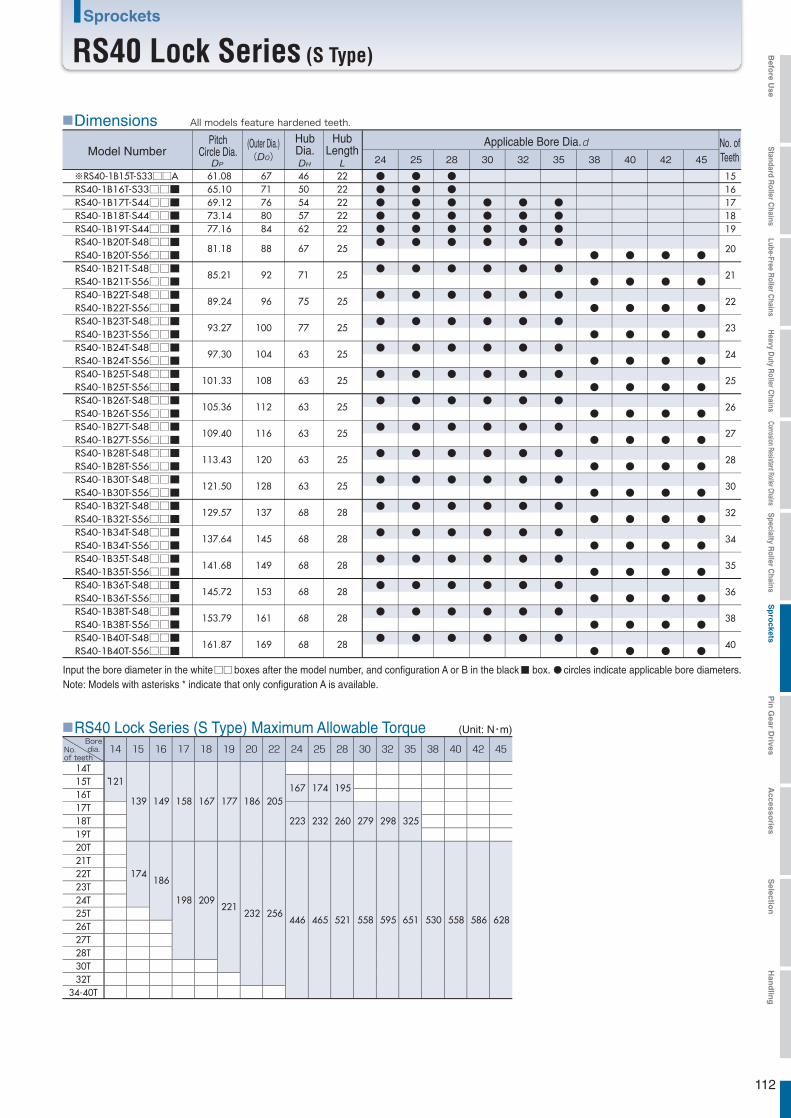
24 25 28 30 32 35
RS40-1B15T-S33□□ARS40-1B16T-S33□□■RS40-1B17T-S44□□■RS40-1B18T-S44□□■RS40-1B19T-S44□□■RS40-1B20T-S48□□■RS40-1B20T-S56□□■RS40-1B21T-S48□□■RS40-1B21T-S56□□■RS40-1B22T-S48□□■RS40-1B22T-S56□□■RS40-1B23T-S48□□■RS40-1B23T-S56□□■RS40-1B24T-S48□□■RS40-1B24T-S56□□■RS40-1B25T-S48□□■RS40-1B25T-S56□□■RS40-1B26T-S48□□■RS40-1B26T-S56□□■RS40-1B27T-S48□□■RS40-1B27T-S56□□■RS40-1B28T-S48□□■RS40-1B28T-S56□□■RS40-1B30T-S48□□■RS40-1B30T-S56□□■RS40-1B32T-S48□□■RS40-1B32T-S56□□■RS40-1B34T-S48□□■RS40-1B34T-S56□□■RS40-1B35T-S48□□■RS40-1B35T-S56□□■RS40-1B36T-S48□□■RS40-1B36T-S56□□■RS40-1B38T-S48□□■RS40-1B38T-S56□□■RS40-1B40T-S48□□■RS40-1B40T-S56□□■
61.08 65.10 69.12 73.14 77.16
81.18
85.21
89.24
93.27
97.30
101.33
105.36
109.40
113.43
121.50
129.57
137.64
141.68
145.72
153.79
161.87
67 71 76 80 84
88
92
96
100
104
108
112
116
120
128
137
145
149
153
161
169
2222222222
25
25
25
25
25
25
25
25
25
25
28
28
28
28
28
28
4650545762
67
71
75
77
63
63
63
63
63
63
68
68
68
68
68
68
●●●●●●
●
●
●
●
●
●
●
●
●
●
●
●
●
●
●
●●●●●●
●
●
●
●
●
●
●
●
●
●
●
●
●
●
●
●●●●●●
●
●
●
●
●
●
●
●
●
●
●
●
●
●
●
●●●●
●
●
●
●
●
●
●
●
●
●
●
●
●
●
●
●●●●
●
●
●
●
●
●
●
●
●
●
●
●
●
●
●
●●●●
●
●
●
●
●
●
●
●
●
●
●
●
●
●
●
38 40 42 45
●
●
●
●
●
●
●
●
●
●
●
●
●
●
●
●
●
●
●
●
●
●
●
●
●
●
●
●
●
●
●
●
●
●
●
●
●
●
●
●
●
●
●
●
●
●
●
●
●
●
●
●
●
●
●
●
●
●
●
●
●
●
●
●
1516171819
20
21
22
23
24
25
26
27
28
30
32
34
35
36
38
40
※
14T15T16T17T18T19T20T21T22T23T24T25T26T27T28T30T32T
34-40T
121
139
174
149
186
158
198
167
209
177
221
186
232
205
256
167
223
446
174
232
465
195
260
521
279
558
298
595
325
651 530 558 586 628
112
Sprockets
RS40 Lock Series (S Type)
■RS40 Lock Series (S Type) Maximum Allowable Torque
■Dimensions
Input the bore diameter in the white boxes after the model number, and configuration A or B in the black box. circles indicate applicable bore diameters.Note: Models with asterisks * indicate that only configuration A is available.
Model NumberNo. ofTeeth
PitchCircle Dia.
(Outer Dia.) HubDia.
HubLength
Applicable Bore Dia.
All models feature hardened teeth.
(Unit: N・m)Boredia.No.
of teeth
Befo
re Use
Standard R
oller Chains
Lube-Free Roller C
hainsH
eavy Duty R
oller Chains
Corrosion Resistant Roller ChainsS
pecialty Roller C
hainsS
pro
cketsP
in G
ear Drives
Accesso
riesS
election
Han
dlin
g
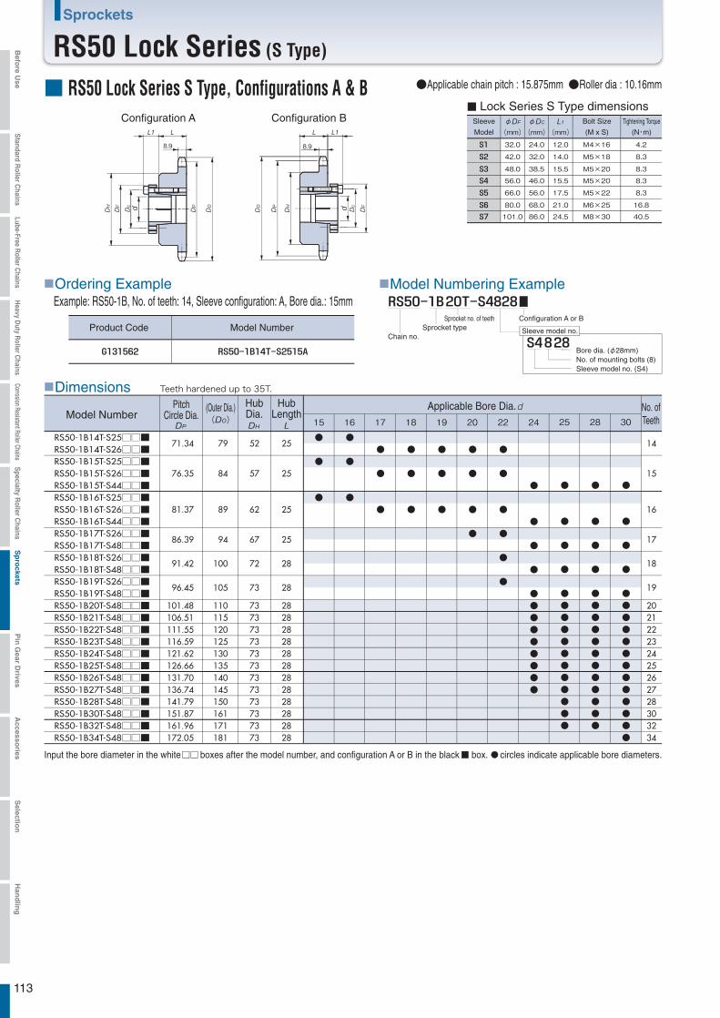
15 16 17 18 19 20 22 24
RS50-1B14T-S25□□■RS50-1B14T-S26□□■RS50-1B15T-S25□□■RS50-1B15T-S26□□■RS50-1B15T-S44□□■RS50-1B16T-S25□□■RS50-1B16T-S26□□■RS50-1B16T-S44□□■RS50-1B17T-S26□□■RS50-1B17T-S48□□■RS50-1B18T-S26□□■RS50-1B18T-S48□□■RS50-1B19T-S26□□■RS50-1B19T-S48□□■RS50-1B20T-S48□□■RS50-1B21T-S48□□■RS50-1B22T-S48□□■RS50-1B23T-S48□□■RS50-1B24T-S48□□■RS50-1B25T-S48□□■RS50-1B26T-S48□□■RS50-1B27T-S48□□■RS50-1B28T-S48□□■RS50-1B30T-S48□□■RS50-1B32T-S48□□■RS50-1B34T-S48□□■
71.34
76.35
81.37
86.39
91.42
96.45
101.48 106.51 111.55 116.59 121.62 126.66 131.70 136.74 141.79 151.87 161.96 172.05
79
84
89
94
100
105
110 115 120 125 130 135 140 145 150 161 171 181
25
25
25
25
28
28
282828282828282828282828
●
●
●
●
●●●●●●●●●
●
●
●
●
●
●
●
●
●
●
●
●
●
●
●
●
●
●
●
●
●
●
●
●
●
52
57
62
67
72
73
737373737373737373737373
14
15
16
17
18
19
202122232425262728303234
25 28 30
●
●
●
●
●●●●●●●●●●●●
●
●
●
●
●●●●●●●●●●●●
●
●
●
●
●●●●●●●●●●●●●
φmm
φmm mm
32.0 24.0 12.0 M4×16 4.2
42.0 32.0 14.0 M5×18 8.3
48.0 38.5 15.5 M5×20 8.3
56.0 46.0 15.5 M5×20 8.3
66.0 56.0 17.5 M5×22 8.3
80.0 68.0 21.0 M6×25 16.8
101.0 86.0 24.5 M8×30 40.5
8.9
8.9
113
Sprockets
RS50 Lock Series (S Type)
■ RS50 Lock Series S Type, Configurations A & BConfiguration BConfiguration A Sleeve
Model
Bolt Size
(M x S)
Tightening Torque
(N・m)
■ Lock Series S Type dimensions
●Applicable chain pitch : 15.875mm ●Roller dia : 10.16mm
■Dimensions
Example: RS50-1B, No. of teeth: 14, Sleeve configuration: A, Bore dia.: 15mm■Model Numbering Example
Sleeve model no.
■Ordering Example
Product Code Model NumberChain no.
Sprocket typeSprocket no. of teeth Configuration A or B
Bore dia. (φ28mm)No. of mounting bolts (8)Sleeve model no. (S4)
Input the bore diameter in the white boxes after the model number, and configuration A or B in the black box. circles indicate applicable bore diameters.
Model NumberNo. ofTeeth
PitchCircle Dia.
(Outer Dia.) HubDia.
HubLength
Applicable Bore Dia.
Teeth hardened up to 35T.
Befo
re Use
Standard R
oller Chains
Lube-Free Roller C
hainsH
eavy Duty R
oller Chains
Corrosion Resistant Roller ChainsS
pecialty Roller C
hainsS
pro
cketsP
in G
ear Drives
Accesso
riesS
election
Han
dlin
g

32 35 38 40 42 45
RS50-1B15T-S44□□■RS50-1B16T-S44□□■RS50-1B17T-S48□□■RS50-1B17T-S56□□■RS50-1B18T-S48□□■RS50-1B18T-S56□□■RS50-1B19T-S48□□■RS50-1B19T-S56□□■RS50-1B20T-S48□□■RS50-1B20T-S56□□■RS50-1B21T-S48□□■RS50-1B21T-S56□□■RS50-1B22T-S48□□■RS50-1B22T-S56□□■RS50-1B23T-S48□□■RS50-1B23T-S56□□■RS50-1B24T-S48□□■RS50-1B24T-S56□□■RS50-1B25T-S48□□■RS50-1B25T-S56□□■RS50-1B26T-S48□□■RS50-1B26T-S56□□■RS50-1B27T-S48□□■RS50-1B27T-S56□□■RS50-1B28T-S48□□■RS50-1B28T-S56□□■RS50-1B30T-S48□□■RS50-1B30T-S56□□■RS50-1B32T-S48□□■RS50-1B32T-S56□□■RS50-1B34T-S48□□■RS50-1B34T-S56□□■RS50-1B35T-S48□□■RS50-1B35T-S56□□■RS50-1B36T-S510□□■RS50-1B36T-S66□□■RS50-1B38T-S510□□■RS50-1B38T-S66□□■RS50-1B40T-S510□□■RS50-1B40T-S66□□■
76.35 81.37
86.39
91.42
96.45
101.48
106.51
111.55
116.59
121.62
126.66
131.70
136.74
141.79
151.87
161.96
172.05
177.10
182.15
192.24
202.33
84 89
94
100
105
110
115
120
125
130
135
140
145
150
161
171
181
186
191
201
211
2525
25
28
28
28
28
28
28
28
28
28
28
28
28
28
28
28
35
35
35
5762
67
72
73
73
73
73
73
73
73
73
73
73
73
73
73
73
83
83
83
●●●
●
●
●
●
●
●
●
●
●
●
●
●
●
●
●
●●●
●
●
●
●
●
●
●
●
●
●
●
●
●
●
●
●
●
●
●
●
●
●
●
●
●
●
●
●
●
●
●●
●
●
●
●
●
●
●
●
●
●
●
●
●
●
●
●
●
●●
●
●
●
●
●
●
●
●
●
●
●
●
●
●
●
●
●
●●
●
●
●
●
●
●
●
●
●
●
●
●
●
●
●
●
●
●●
●
●
48 50 55
●
●
●
●
●
●
●
●
●
1516
17
18
19
20
21
22
23
24
25
26
27
28
30
32
34
35
36
38
40
14T15T16T17T18T19T20T21T22T23T24T25T26T27T28T30T32T34T35T
36-40T
174 186 237 251 265279
307223
446
232
465
260
521
279
558
298
595
325
651 530
883
558
930
586
976
628
1046 1116 1162 1279
114
Sprockets
RS50 Lock Series (S Type)
■RS50 Lock Series (S Type) Maximum Allowable Torque
■Dimensions
Input the bore diameter in the white boxes after the model number, and configuration A or B in the black box. circles indicate applicable bore diameters.
Teeth hardened up to 35T.
(Unit: N・m)
Model NumberNo. ofTeeth
PitchCircle Dia.
(Outer Dia.) HubDia.
HubLength
Applicable Bore Dia.
Boredia.No.
of teeth
Befo
re Use
Standard R
oller Chains
Lube-Free Roller C
hainsH
eavy Duty R
oller Chains
Corrosion Resistant Roller ChainsS
pecialty Roller C
hainsS
pro
cketsP
in G
ear Drives
Accesso
riesS
election
Han
dlin
g
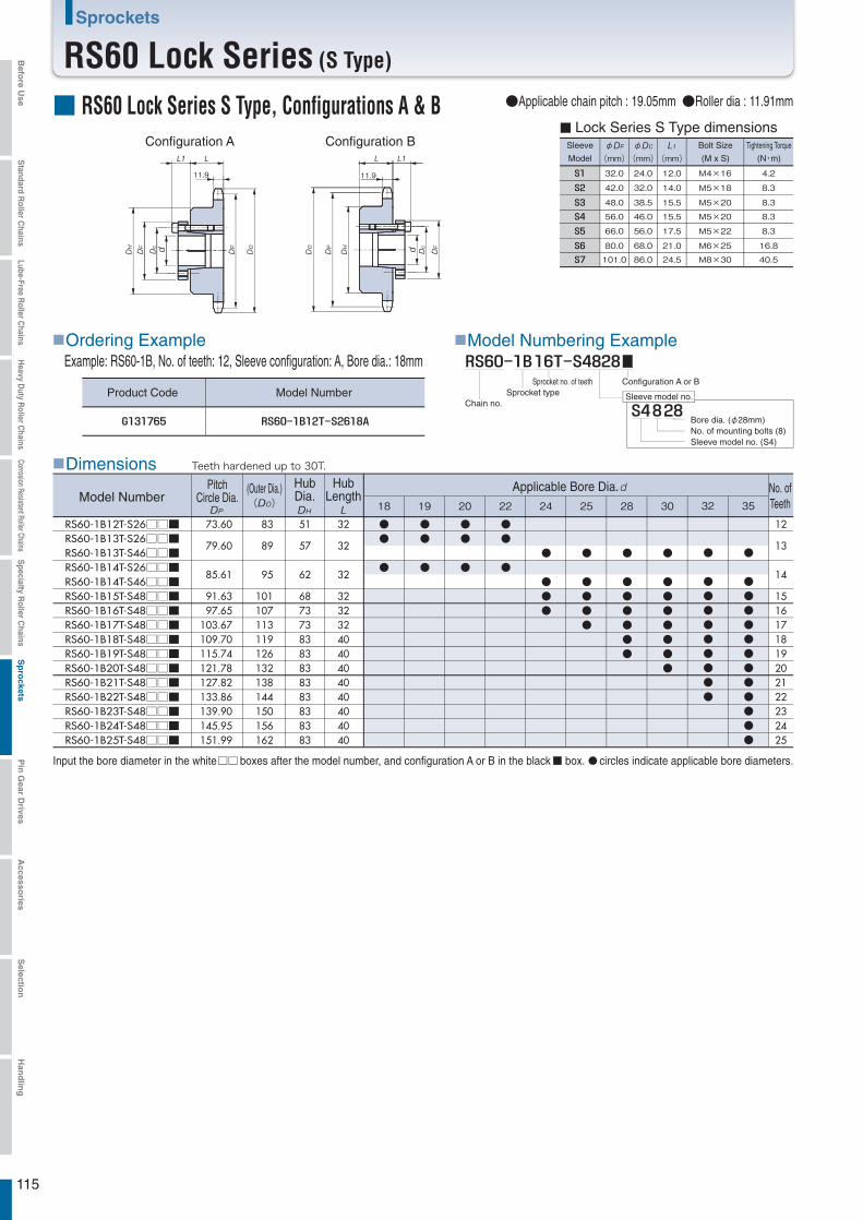
18 19 20 22 24 25 28 30
RS60-1B12T-S26□□■RS60-1B13T-S26□□■RS60-1B13T-S46□□■RS60-1B14T-S26□□■RS60-1B14T-S46□□■RS60-1B15T-S48□□■RS60-1B16T-S48□□■RS60-1B17T-S48□□■RS60-1B18T-S48□□■RS60-1B19T-S48□□■RS60-1B20T-S48□□■RS60-1B21T-S48□□■RS60-1B22T-S48□□■RS60-1B23T-S48□□■RS60-1B24T-S48□□■RS60-1B25T-S48□□■
73.60
79.60
85.61
91.63 97.65
103.67 109.70 115.74 121.78 127.82 133.86 139.90 145.95 151.99
83
89
95
101 107 113 119 126 132 138 144 150 156 162
32
32
32
3232324040404040404040
●
●●●●●●●
●●
●●
●●●●●●
●●
●
●●
●
●●
●●
●●●●
●
●●●
51
57
62
6873738383838383838383
12
13
14
1516171819202122232425
32 35
●
●●●●●●●●●
●
●●●●●●●●●●●●
φmm
φmm mm
32.0 24.0 12.0 M4×16 4.2
42.0 32.0 14.0 M5×18 8.3
48.0 38.5 15.5 M5×20 8.3
56.0 46.0 15.5 M5×20 8.3
66.0 56.0 17.5 M5×22 8.3
80.0 68.0 21.0 M6×25 16.8
101.0 86.0 24.5 M8×30 40.5
11.9
11.9
115
Sprockets
RS60 Lock Series (S Type)
■ RS60 Lock Series S Type, Configurations A & BConfiguration BConfiguration A Sleeve
Model
Bolt Size
(M x S)
Tightening Torque
(N・m)
■ Lock Series S Type dimensions
●Applicable chain pitch : 19.05mm ●Roller dia : 11.91mm
■Dimensions
Example: RS60-1B, No. of teeth: 12, Sleeve configuration: A, Bore dia.: 18mm■Model Numbering Example
Sleeve model no.
■Ordering Example
Product Code Model NumberChain no.
Sprocket typeSprocket no. of teeth Configuration A or B
Bore dia. (φ28mm)No. of mounting bolts (8)Sleeve model no. (S4)
Input the bore diameter in the white boxes after the model number, and configuration A or B in the black box. circles indicate applicable bore diameters.
Model NumberNo. ofTeeth
PitchCircle Dia.
(Outer Dia.) HubDia.
HubLength
Applicable Bore Dia.
Teeth hardened up to 30T.
Befo
re Use
Standard R
oller Chains
Lube-Free Roller C
hainsH
eavy Duty R
oller Chains
Corrosion Resistant Roller ChainsS
pecialty Roller C
hainsS
pro
cketsP
in G
ear Drives
Accesso
riesS
election
Han
dlin
g
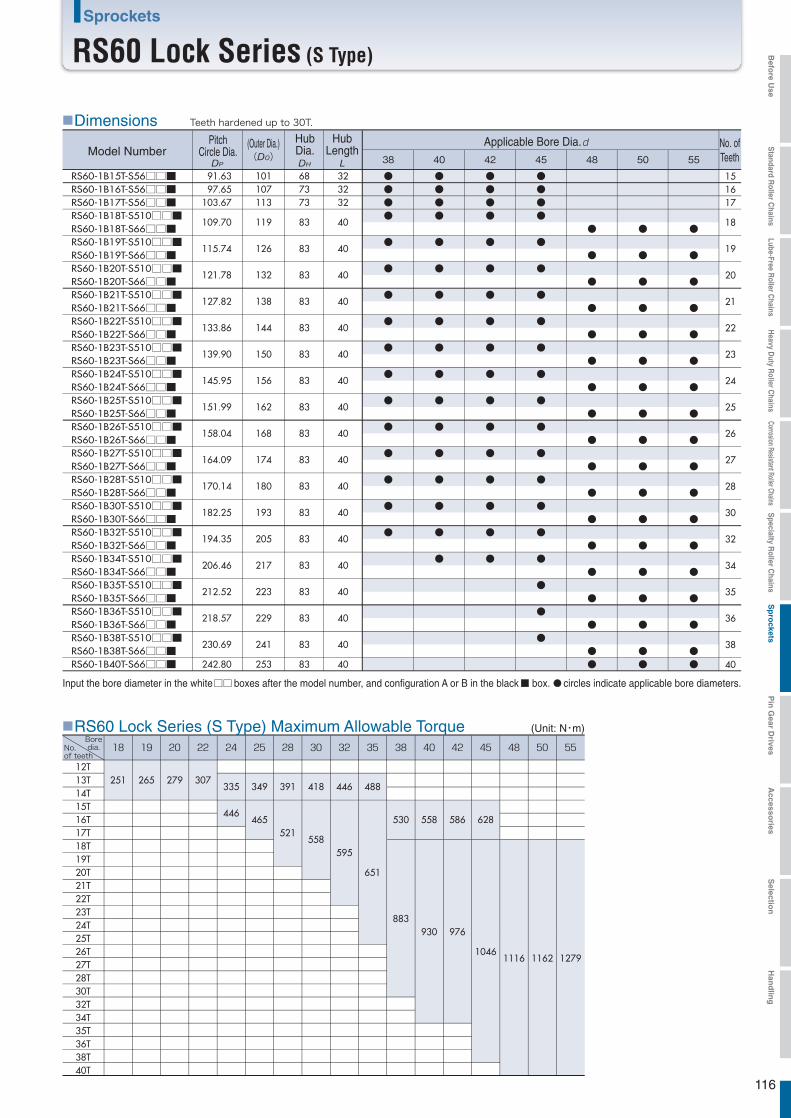
38 40 42 45 48 50
RS60-1B15T-S56□□■RS60-1B16T-S56□□■RS60-1B17T-S56□□■RS60-1B18T-S510□□■RS60-1B18T-S66□□■RS60-1B19T-S510□□■RS60-1B19T-S66□□■RS60-1B20T-S510□□■RS60-1B20T-S66□□■RS60-1B21T-S510□□■RS60-1B21T-S66□□■RS60-1B22T-S510□□■RS60-1B22T-S66□□■RS60-1B23T-S510□□■RS60-1B23T-S66□□■RS60-1B24T-S510□□■RS60-1B24T-S66□□■RS60-1B25T-S510□□■RS60-1B25T-S66□□■RS60-1B26T-S510□□■RS60-1B26T-S66□□■RS60-1B27T-S510□□■RS60-1B27T-S66□□■RS60-1B28T-S510□□■RS60-1B28T-S66□□■RS60-1B30T-S510□□■RS60-1B30T-S66□□■RS60-1B32T-S510□□■RS60-1B32T-S66□□■RS60-1B34T-S510□□■RS60-1B34T-S66□□■RS60-1B35T-S510□□■RS60-1B35T-S66□□■RS60-1B36T-S510□□■RS60-1B36T-S66□□■RS60-1B38T-S510□□■RS60-1B38T-S66□□■RS60-1B40T-S66□□■
91.63 97.65
103.67
109.70
115.74
121.78
127.82
133.86
139.90
145.95
151.99
158.04
164.09
170.14
182.25
194.35
206.46
212.52
218.57
230.69
242.80
101 107 113
119
126
132
138
144
150
156
162
168
174
180
193
205
217
223
229
241
253
323232
40
40
40
40
40
40
40
40
40
40
40
40
40
40
40
40
40
40
687373
83
83
83
83
83
83
83
83
83
83
83
83
83
83
83
83
83
83
●●●●
●
●
●
●
●
●
●
●
●
●
●
●
●●●●
●
●
●
●
●
●
●
●
●
●
●
●
●
●●●●
●
●
●
●
●
●
●
●
●
●
●
●
●
●●●●
●
●
●
●
●
●
●
●
●
●
●
●
●
●
●
●
●
●
●
●
●
●
●
●
●
●
●
●
●
●
●
●
●●
●
●
●
●
●
●
●
●
●
●
●
●
●
●
●
●
●●
55
●
●
●
●
●
●
●
●
●
●
●
●
●
●
●
●
●●
151617
18
19
20
21
22
23
24
25
26
27
28
30
32
34
35
36
38
40
12T13T14T15T16T17T18T19T20T21T22T23T24T25T26T27T28T30T32T34T35T36T38T40T
251 265 279 307335
446
349
465
391
521
418
558
446
595
488
651
530
883
558
930
586
976
628
10461116 1162 1279
116
Sprockets
RS60 Lock Series (S Type)
■RS60 Lock Series (S Type) Maximum Allowable Torque
■Dimensions
Input the bore diameter in the white boxes after the model number, and configuration A or B in the black box. circles indicate applicable bore diameters.
Teeth hardened up to 30T.
(Unit: N・m)
Model NumberNo. ofTeeth
PitchCircle Dia.
(Outer Dia.) HubDia.
HubLength
Applicable Bore Dia.
Boredia.No.
of teeth
Befo
re Use
Standard R
oller Chains
Lube-Free Roller C
hainsH
eavy Duty R
oller Chains
Corrosion Resistant Roller ChainsS
pecialty Roller C
hainsS
pro
cketsP
in G
ear Drives
Accesso
riesS
election
Han
dlin
g
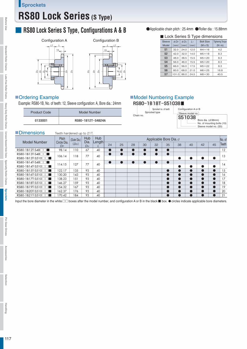
24 25 28 30 32 35 38 40
RS80-1B12T-S48□□■RS80-1B13T-S48□□■RS80-1B13T-S510□□■RS80-1B14T-S48□□■RS80-1B14T-S510□□■RS80-1B15T-S510□□■RS80-1B16T-S510□□■RS80-1B17T-S510□□■RS80-1B18T-S510□□■RS80-1B19T-S510□□■RS80-1B20T-S510□□■RS80-1B21T-S510□□■
98.14
106.14
114.15
122.17 130.20 138.23 146.27 154.32 162.37 170.42
110
118
127
135 143 151 159 167 176 184
40
40
40
40404040404040
●
●●●●●●●●
●●
●●
●●●●●●●●
●●
●
●●
●
●●
●
●●
●
●●●●●●●
●●
●
67
77
77
93939393939393
12
13
14
15161718192021
42 45
●
●●●●●●●●
●
●●●●●●●●
φmm
φmm mm
32.0 24.0 12.0 M4×16 4.2
42.0 32.0 14.0 M5×18 8.3
48.0 38.5 15.5 M5×20 8.3
56.0 46.0 15.5 M5×20 8.3
66.0 56.0 17.5 M5×22 8.3
80.0 68.0 21.0 M6×25 16.8
101.0 86.0 24.5 M8×30 40.5
15
15
117
Sprockets
RS80 Lock Series (S Type)
■ RS80 Lock Series S Type, Configurations A & BConfiguration BConfiguration A Sleeve
Model
Bolt Size
(M x S)
Tightening Torque
(N・m)
■ Lock Series S Type dimensions
●Applicable chain pitch : 25.4mm ●Roller dia : 15.88mm
■Dimensions
Example: RS80-1B, No. of teeth: 12, Sleeve configuration: A, Bore dia.: 24mm■Model Numbering Example
Sleeve model no.
■Ordering Example
Product Code Model NumberChain no.
Sprocket typeSprocket no. of teeth Configuration A or B
Bore dia. (φ38mm)No. of mounting bolts (10)Sleeve model no. (S5)
Input the bore diameter in the white boxes after the model number, and configuration A or B in the black box. circles indicate applicable bore diameters.
Model NumberNo. ofTeeth
PitchCircle Dia.
(Outer Dia.) HubDia.
HubLength
Applicable Bore Dia.
Teeth hardened up to 21T.
Befo
re Use
Standard R
oller Chains
Lube-Free Roller C
hainsH
eavy Duty R
oller Chains
Corrosion Resistant Roller ChainsS
pecialty Roller C
hainsS
pro
cketsP
in G
ear Drives
Accesso
riesS
election
Han
dlin
g
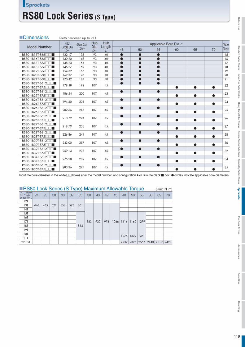
48 50 55 60 65 70
RS80-1B15T-S66□□■RS80-1B16T-S66□□■RS80-1B17T-S66□□■RS80-1B18T-S66□□■RS80-1B19T-S66□□■RS80-1B20T-S68□□■RS80-1B21T-S68□□■RS80-1B22T-S612□□■RS80-1B22T-S75□□■RS80-1B23T-S612□□■RS80-1B23T-S75□□■RS80-1B24T-S612□□■RS80-1B24T-S75□□■RS80-1B25T-S612□□■RS80-1B25T-S75□□■RS80-1B26T-S612□□■RS80-1B26T-S75□□■RS80-1B27T-S612□□■RS80-1B27T-S75□□■RS80-1B28T-S612□□■RS80-1B28T-S75□□■RS80-1B30T-S612□□■RS80-1B30T-S75□□■RS80-1B32T-S612□□■RS80-1B32T-S75□□■RS80-1B34T-S612□□■RS80-1B34T-S75□□■RS80-1B35T-S612□□■RS80-1B35T-S75□□■
122.17 130.20 138.23 146.27 154.32 162.37 170.42
178.48
186.54
194.60
202.66
210.72
218.79
226.86
243.00
259.14
275.28
283.36
135 143 151 159 167 176 184
192
200
208
216
224
233
241
257
273
289
297
40404040404040
45
45
45
45
45
45
45
45
45
45
45
93939393939393
107
107
107
107
107
107
107
107
107
107
107
●●●●●●●●
●
●
●
●
●
●
●
●
●
●
●●●●●●●●
●
●
●
●
●
●
●
●
●
●
●●●●●●●●
●
●
●
●
●
●
●
●
●
●
●
●
●
●
●
●
●
●
●
●
●
●
●
●
●
●
●
●
●
●
●
●
●
●
●
●
●
●
●
●
●
●
●
15161718192021
22
23
24
25
26
27
28
30
32
34
35
12T13T14T15T16T17T18T19T20T21T
22-35T
446 465 521 558 595 651
814883 930 976 1046 1116
1275
2232
1162
1329
2325
1279
1461
2557 2140 2319 2497
118
Sprockets
RS80 Lock Series (S Type)
■RS80 Lock Series (S Type) Maximum Allowable Torque
■Dimensions
Input the bore diameter in the white boxes after the model number, and configuration A or B in the black box. circles indicate applicable bore diameters.
Teeth hardened up to 21T.
(Unit: N・m)
Model NumberNo. ofTeeth
PitchCircle Dia.
(Outer Dia.) HubDia.
HubLength
Applicable Bore Dia.
Boredia.No.
of teeth
Befo
re Use
Standard R
oller Chains
Lube-Free Roller C
hainsH
eavy Duty R
oller Chains
Corrosion Resistant Roller ChainsS
pecialty Roller C
hainsS
pro
cketsP
in G
ear Drives
Accesso
riesS
election
Han
dlin
g
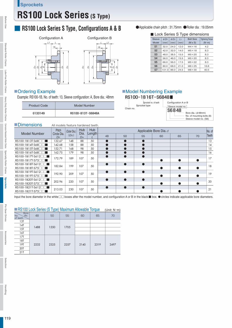
48 50 55 60 65 70
RS100-1B13T-S68□□■RS100-1B14T-S68□□■RS100-1B15T-S68□□■RS100-1B16T-S68□□■RS100-1B17T-S612□□■RS100-1B17T-S75□□■RS100-1B18T-S612□□■RS100-1B18T-S75□□■RS100-1B19T-S612□□■RS100-1B19T-S75□□■RS100-1B20T-S612□□■RS100-1B20T-S75□□■RS100-1B21T-S612□□■RS100-1B21T-S75□□■
132.67 142.68 152.71 162.75
172.79
182.84
192.90
202.96
213.03
148 158 168 179
189
199
209
220
230
50505050
50
50
50
50
50
●●●●●
●
●
●
●
●●●●●
●
●
●
●
●●●●●
●
●
●
●
●
●
●
●
●
●
●
●
●
●
●
●
●
●
●
88889898
107
107
107
107
107
13141516
17
18
19
20
21
φmm
φmm mm
32.0 24.0 12.0 M4×16 4.2
42.0 32.0 14.0 M5×18 8.3
48.0 38.5 15.5 M5×20 8.3
56.0 46.0 15.5 M5×20 8.3
66.0 56.0 17.5 M5×22 8.3
80.0 68.0 21.0 M6×25 16.8
101.0 86.0 24.5 M8×30 40.5
18
18
13T14T15T16T17T18T19T20T21T
1488
2232
1550
2325
1705
2257 2140 2319 2497
119
Sprockets
RS100 Lock Series (S Type)
■ RS100 Lock Series S Type, Configurations A & BConfiguration BConfiguration A Sleeve
Model
Bolt Size
(M x S)
Tightening Torque
(N・m)
■ Lock Series S Type dimensions
●Applicable chain pitch : 31.75mm ●Roller dia : 19.05mm
■Dimensions
Example: RS100-1B, No. of teeth: 13, Sleeve configuration: A, Bore dia.: 48mm■Model Numbering Example
Sleeve model no.
■Ordering Example
Product Code Model NumberChain no.
Sprocket typeSprocket no. of teeth Configuration A or B
Bore dia. (φ48mm)No. of mounting bolts (8)Sleeve model no. (S6)
Input the bore diameter in the white boxes after the model number, and configuration A or B in the black box. circles indicate applicable bore diameters.
Model NumberNo. ofTeeth
PitchCircle Dia.
(Outer Dia.) HubDia.
HubLength
Applicable Bore Dia.
All models feature hardened teeth.
■RS100 Lock Series (S Type) Maximum Allowable Torque (Unit: N・m)Boredia.No.
of teeth
Befo
re Use
Standard R
oller Chains
Lube-Free Roller C
hainsH
eavy Duty R
oller Chains
Corrosion Resistant Roller ChainsS
pecialty Roller C
hainsS
pro
cketsP
in G
ear Drives
Accesso
riesS
election
Han
dlin
g
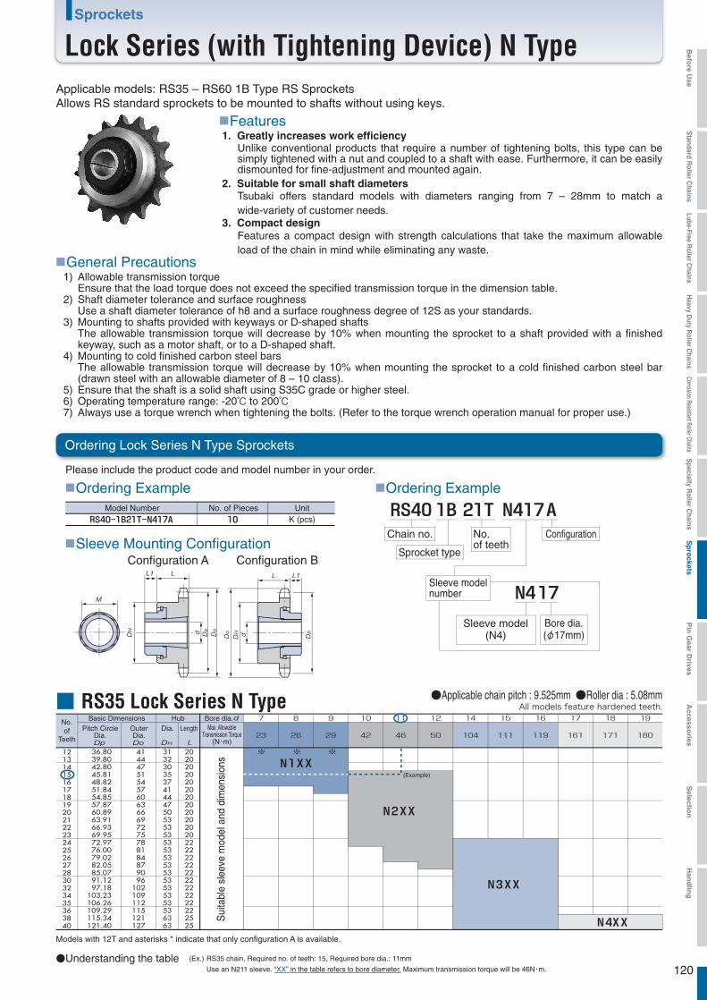
ConfigurationNo.of teeth
120
Sprockets
Lock Series (with Tightening Device) N Type
■Ordering Example ■Ordering Example
Chain no.
Sprocket type
Sleeve model(N4)
Bore dia.(φ17mm)
Sleeve modelnumber
■Sleeve Mounting Configuration
■General Precautions
●Understanding the table
All models feature hardened teeth.
※ ※ ※
No.of
Teeth
121314151617181920212223242526272830323435363840
202020202020202020202020222222222222222222222525
313230353741444750535353535353535353535353536363
414447515457606366697275788184879096
102109112115121127
36.8039.8042.8045.8148.8251.8454.8557.8760.8963.9166.9369.9572.9776.0079.0282.0585.0791.1297.18
103.23106.26109.29115.34121.40
(Ex.) RS35 chain, Required no. of teeth: 15, Required bore dia.: 11mm
Use an N211 sleeve. “XX” in the table refers to bore diameter. Maximum transmission torque will be 46N・m.
Applicable models: RS35 – RS60 1B Type RS SprocketsAllows RS standard sprockets to be mounted to shafts without using keys.
■Features 1. Greatly increases work efficiency
2. Suitable for small shaft diameters
3. Compact design
Unlike conventional products that require a number of tightening bolts, this type can be simply tightened with a nut and coupled to a shaft with ease. Furthermore, it can be easily dismounted for fine-adjustment and mounted again.
Features a compact design with strength calculations that take the maximum allowable load of the chain in mind while eliminating any waste.
Tsubaki offers standard models with diameters ranging from 7 – 28mm to match a wide-variety of customer needs.
Allowable transmission torqueEnsure that the load torque does not exceed the specified transmission torque in the dimension table.Shaft diameter tolerance and surface roughnessUse a shaft diameter tolerance of h8 and a surface roughness degree of 12S as your standards.Mounting to shafts provided with keyways or D-shaped shaftsThe allowable transmission torque will decrease by 10% when mounting the sprocket to a shaft provided with a finished keyway, such as a motor shaft, or to a D-shaped shaft.Mounting to cold finished carbon steel barsThe allowable transmission torque will decrease by 10% when mounting the sprocket to a cold finished carbon steel bar (drawn steel with an allowable diameter of 8 – 10 class).Ensure that the shaft is a solid shaft using S35C grade or higher steel.Operating temperature range: -20℃ to 200℃Always use a torque wrench when tightening the bolts. (Refer to the torque wrench operation manual for proper use.)
1)
2)
3)
4)
5)6)7)
Please include the product code and model number in your order.
Ordering Lock Series N Type Sprockets
Model Number No. of Pieces UnitK (pcs)
Configuration A Configuration B
■ RS35 Lock Series N Type ●Applicable chain pitch : 9.525mm ●Roller dia : 5.08mm
Max. AllowableTransmission Torque
(N・m)
Basic Dimensions Hub Bore dia.Pitch Circle
Dia.OuterDia.
Dia. Length
Sui
tabl
e sl
eeve
mod
el a
nd d
imen
sion
s
(Example)
Models with 12T and asterisks * indicate that only configuration A is available.
Befo
re Use
Standard R
oller Chains
Lube-Free Roller C
hainsH
eavy Duty R
oller Chains
Corrosion Resistant Roller ChainsS
pecialty Roller C
hainsS
pro
cketsP
in G
ear Drives
Accesso
riesS
election
Han
dlin
g

Sleeve Protrusion
※ ※ ※※ ※ ※
※ ※ ※※ ※ ※ ※ ※ ※
※ ※ ※
※ ※ ※※ ※ ※
※ ※ ※
11121314151617181920212223242526272830323435363840
22222222222222222225252525252525252525282828282828
37403742465054576267717577636363636363686868686868
515559636771768084889296
100104108112116120128137145149153161169
45.0849.0753.0757.0761.0865.1069.1273.1477.1681.1885.2189.2493.2797.30
101.33105.36109.40113.43121.50129.57137.64141.68145.72153.79161.87
111213141516171819202122232425
252525252525252828282828282828
465151525762677273737373737373
64697479848994
100105110115120125130135
56.3561.3466.3371.3476.3581.3786.3991.4296.45
101.48106.51111.55116.59121.62126.66
910111213141516171819202122232425
3232323232323232324040404040404040
4349515157626873738383838383838383
647076838995
101107113119126132138144150156162
55.7061.6567.6273.6079.6085.6191.6397.65
103.67109.70115.74121.78127.82133.86139.90145.95151.99
121
Sprockets
RS35 – RS60 Lock Series (N Type)
Configuration A Configuration BSleeve
Model
Nut Width Across Flats
(M x S)
Nut Tightening Torque
(N・m)
■ Lock Series N Type dimensions
●Applicable chain pitch : 12.7mm ●Roller dia : 7.92mmAll models feature hardened teeth.■ RS40 Lock Series N Type
No.of
Teeth
Max. AllowableTransmission Torque
(N・m)
Basic Dimensions Hub Bore dia.Pitch Circle
Dia.OuterDia.
Dia. Length
Sui
tabl
e sl
eeve
mod
el a
nd d
imen
sion
s
Models with 11 and 12T and asterisks * indicate that only configuration A is available.
●Applicable chain pitch : 15.875mm ●Roller dia : 10.16mmAll models feature hardened teeth.■ RS50 Lock Series N Type
No.of
Teeth
Max. AllowableTransmission Torque
(N・m)
Basic Dimensions Hub Bore dia.Pitch Circle
Dia.OuterDia.
Dia. Length
Suita
ble sl
eeve
mod
el an
d dim
ensio
ns
Models with 11, 12, and 13T and asterisks * indicate that only configuration A is available.
●Applicable chain pitch : 19.05mm ●Roller dia : 11.91mmAll models feature hardened teeth.■ RS60 Lock Series N Type
No.of
Teeth
Max. AllowableTransmission Torque
(N・m)
Basic Dimensions Hub Bore dia.Pitch Circle
Dia.OuterDia.
Dia. Length
Suita
ble
sleev
e m
odel
and
dim
ensio
ns
Models with 9, 10, and 11T and asterisks * indicate that only configuration A is available.
Befo
re Use
Standard R
oller Chains
Lube-Free Roller C
hainsH
eavy Duty R
oller Chains
Corrosion Resistant Roller ChainsS
pecialty Roller C
hainsS
pro
cketsP
in G
ear Drives
Accesso
riesS
election
Han
dlin
g

122
■ RS11 1B Type with stainless steel pilot bore ■ RS11 1C Type with stainless steel pilot bore
■Stainless steel pilot bore series
■Engineering plastic pilot bore series
■Ordering Example
Product Code Model No. Quantity Unit(pcs)
Stainless steel
Engineering plastic
■Model Numbering Example
335 B
Series
Model No.No.
of Teeth
Pitch CircleDia.
(Outer Dia.)Bore Dia.
)Hub Dia.
Set Screw Hole1B Approx.Mass (g)Pilot bore Max.
1C Approx.Mass (g)
RS11-1■12T-SSRS11-1■15T-SSRS11-1■16T-SSRS11-1■18T-SSRS11-1■20T-SSRS11-1■24T-SSRS11-1■28T-SSRS11-1■30T-SSRS11-1■34T-SSRS11-1■36T-SSRS11-1■40T-SSRS11-1■48T-SS
12
15
16
18
20
24
28
30
34
36
40
48
14.475
18.020
19.204
21.575
23.949
28.703
33.462
35.842
40.604
42.986
47.751
57.283
16.2
19.9
21.1
23.5
25.9
30.7
35.5
37.9
42.7
45.1
49.8
59.4
4
4
4
4
6
6
6
6
6
6
6
6
6
9
9
11
13
13
13
13
13
13
13
13
9.4
13
14
16
19
19
19
19
19
19
19
19
M3×0.5
M4×0.7
1.6
4
0 -0.1
9.710.5
1.6
2.3
9.710.5
4
0 -0.1
5.9
11.5
13.5
17.7
23.3
25.7
28.7
29.7
37.9
40.7
46.5
60.5
7.4
14.7
17.3
22.8
30.8
32.7
35.7
39.3
48.9
52.4
59.9
77.8
Sprockets
RS Sprocket Corrosion Resistant Series
RS11 (Corrosion Resistant Stainless Steel)See pg. 79 for Tsubaki’s corrosion resistant chain series
Contact a Tsubaki representative regarding numbers of teeth other than those above.
See pg. 79 for Tsubaki’s corrosion resistant chain series
Includes our stainless steel pilot bore series with excellent corrosion resistance and our engineering plastic series that can be operated with no lubrication. *See pg. 189 for a table of corrosion resistance.
Uses stainless steel for excellent corrosion resistance. These sprockets are also highly heat and cold resistant and can be used in special environments as well. Tsubaki has a stock of single-strand 1B type sprockets (single-hub type) for RS11 – RS80 chain sizes.
Made of special MC901 nylon (dark blue), these sprockets can be operated without lubrication. Chain speed should not exceed 70m/min, but chain speeds up to 150m/min are possible with additional lubrication. Tsubaki has a limited stock of single-strand 1B type sprockets (single-hub type) for RS35 – RS60 chain sizes.
Ordering Standard Pilot Bore Series Sprockets
Please indicate product code and model number on your order.
Product Code Model No. Quantity Unit(pcs)
Chain no. No.of teeth
1B: single hub1C: Dual hub Stainless steel: -SS
Eng. p last ic : -P
Hub type
Applicable chain pitch: 3.7465mm Roller dia.: 2.285mm
No. of teeth: 12T – 28TNo tooth step
No. of teeth: 30T – 48TWith tooth step
No. of teeth: 12T – 28TNo tooth step
No. of teeth: 30T – 48TWith tooth step
(Be aware that no set screws are provided.)
Material/Specifications Machined stainless steel
Indicate type (B or C) in the ■ in the table above.
Note: Max. shaft bore diameter shown is for general situations. Please decide or confirm shaft bore diameter and key contact stress based on general machine design.
Befo
re Use
Standard R
oller Chains
Lube-Free Roller C
hainsH
eavy Duty R
oller Chains
Corrosion Resistant Roller ChainsS
pecialty Roller C
hainsS
pro
cketsP
in G
ear Drives
Accesso
riesS
election
Han
dlin
g
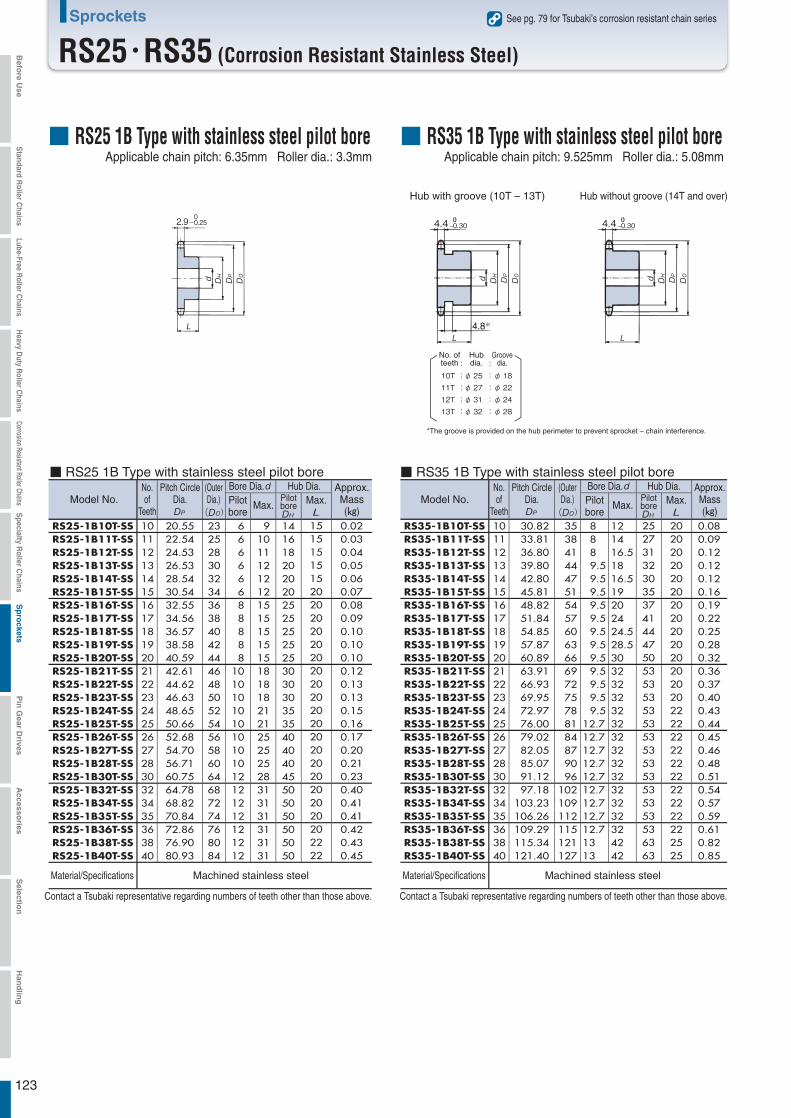
123
Sprockets
RS25・RS35 (Corrosion Resistant Stainless Steel)
Material/Specifications Machined stainless steel Material/Specifications Machined stainless steel
■ RS25 1B Type with stainless steel pilot bore ■ RS35 1B Type with stainless steel pilot bore
Contact a Tsubaki representative regarding numbers of teeth other than those above. Contact a Tsubaki representative regarding numbers of teeth other than those above.
2.9-0.2504.4 -0.30 4.4 -0.30
※
: :10T : φ 25 :φ 1811T : φ 27 :φ 2212T : φ 31 :φ 2413T : φ 32 :φ 28
RS25-1B10T-SSRS25-1B11T-SSRS25-1B12T-SSRS25-1B13T-SSRS25-1B14T-SSRS25-1B15T-SSRS25-1B16T-SSRS25-1B17T-SSRS25-1B18T-SSRS25-1B19T-SSRS25-1B20T-SSRS25-1B21T-SSRS25-1B22T-SSRS25-1B23T-SSRS25-1B24T-SSRS25-1B25T-SSRS25-1B26T-SSRS25-1B27T-SSRS25-1B28T-SSRS25-1B30T-SSRS25-1B32T-SSRS25-1B34T-SSRS25-1B35T-SSRS25-1B36T-SSRS25-1B38T-SSRS25-1B40T-SS
1011121314151617181920212223242526272830323435363840
20.5522.5424.5326.5328.5430.5432.5534.5636.5738.5840.5942.6144.6246.6348.6550.6652.6854.7056.7160.7564.7868.8270.8472.8676.9080.93
2325283032343638404244464850525456586064687274768084
66666688888
101010101010101012121212121212
910111212121515151515181818212125252528313131313131
1416182020202525252525303030353540404045505050505050
1515151515202020202020202020202020202020202020202222
0.020.030.040.050.060.070.080.090.100.100.100.120.130.130.150.160.170.200.210.230.400.410.410.420.430.45
RS35-1B10T-SSRS35-1B11T-SSRS35-1B12T-SSRS35-1B13T-SSRS35-1B14T-SSRS35-1B15T-SSRS35-1B16T-SSRS35-1B17T-SSRS35-1B18T-SSRS35-1B19T-SSRS35-1B20T-SSRS35-1B21T-SSRS35-1B22T-SSRS35-1B23T-SSRS35-1B24T-SSRS35-1B25T-SSRS35-1B26T-SSRS35-1B27T-SSRS35-1B28T-SSRS35-1B30T-SSRS35-1B32T-SSRS35-1B34T-SSRS35-1B35T-SSRS35-1B36T-SSRS35-1B38T-SSRS35-1B40T-SS
1011121314151617181920212223242526272830323435363840
30.82 33.81 36.80 39.80 42.80 45.81 48.82 51.84 54.85 57.87 60.89 63.91 66.93 69.95 72.97 76.00 79.02 82.05 85.07 91.12 97.18103.23106.26109.29115.34121.40
35 38 41 44 47 51 54 57 60 63 66 69 72 75 78 81 84 87 90 96102109112115121127
8 8 8 9.5 9.5 9.5 9.5 9.5 9.5 9.5 9.5 9.5 9.5 9.5 9.512.712.712.712.712.712.712.712.712.71313
121416.51816.519202424.528.530323232323232323232323232324242
2527313230353741444750535353535353535353535353536363
2020202020202020202020202020222222222222222222222525
0.080.090.120.120.120.160.190.220.250.280.320.360.370.400.430.440.450.460.480.510.540.570.590.610.820.85
Hub Dia. Approx.Mass(kg)
Max.Model No.No.of
Teeth
Pitch CircleDia.
(OuterDia.)
Bore Dia.PilotborePilot
boreMax.
See pg. 79 for Tsubaki’s corrosion resistant chain series
■ RS25 1B Type with stainless steel pilot boreApplicable chain pitch: 6.35mm Roller dia.: 3.3mm
■ RS35 1B Type with stainless steel pilot boreApplicable chain pitch: 9.525mm Roller dia.: 5.08mm
Hub without groove (14T and over)Hub with groove (10T – 13T)
Groovedia.
No. ofteeth
Hubdia.
*The groove is provided on the hub perimeter to prevent sprocket – chain interference.
Hub Dia. Approx.Mass(kg)
Model No.No.of
Teeth
Pitch CircleDia.
Bore Dia.(OuterDia.) Pilot
boreMax. Max.Pilot
bore
Befo
re Use
Standard R
oller Chains
Lube-Free Roller C
hainsH
eavy Duty R
oller Chains
Corrosion Resistant Roller ChainsS
pecialty Roller C
hainsS
pro
cketsP
in G
ear Drives
Accesso
riesS
election
Han
dlin
g
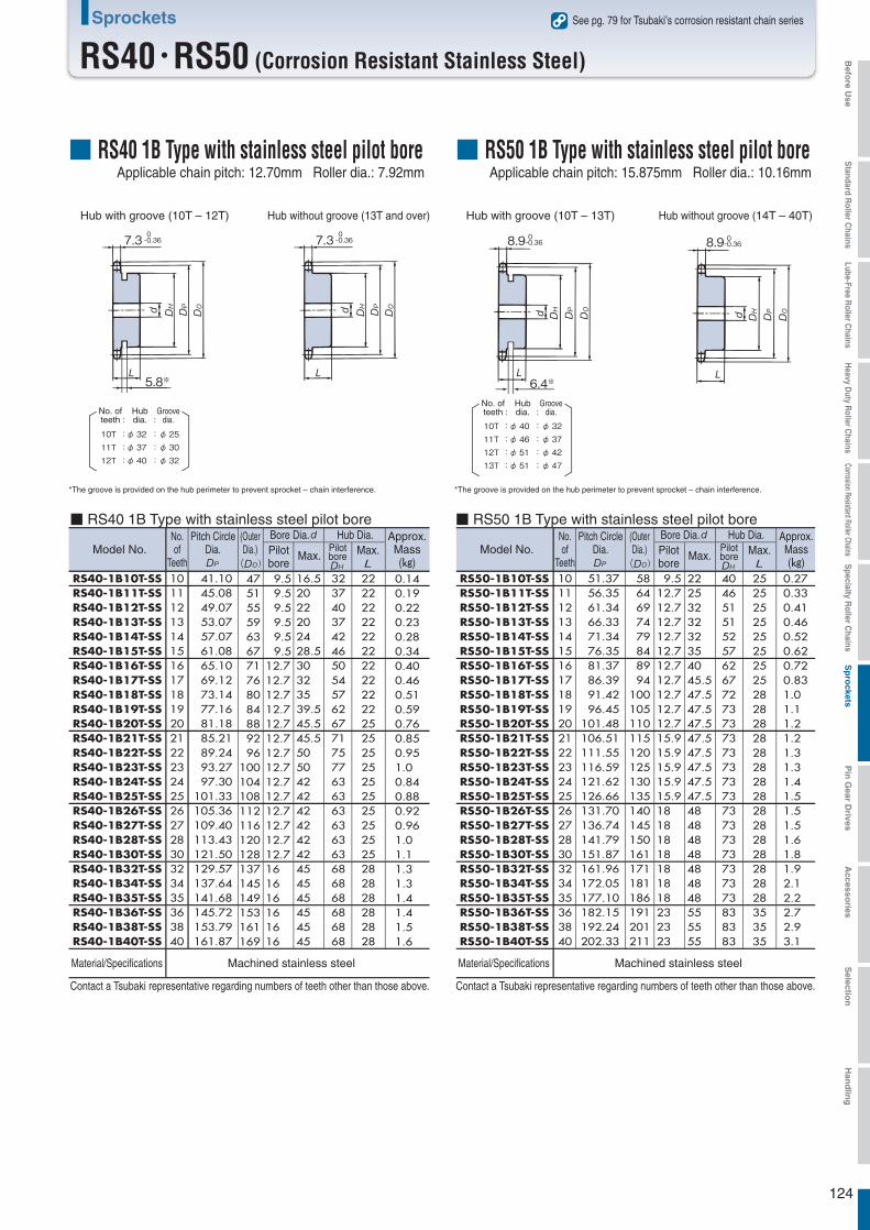
124
Sprockets
RS40・RS50 (Corrosion Resistant Stainless Steel)
*The groove is provided on the hub perimeter to prevent sprocket – chain interference.
10T : φ 32 :φ 2511T : φ 37 :φ 3012T : φ 40 :φ 32
*The groove is provided on the hub perimeter to prevent sprocket – chain interference.
10T : φ 40 :φ 3211T : φ 46 :φ 3712T : φ 51 :φ 4213T : φ 51 :φ 47
7.3 -0.36 0
5.8※
7.3 -0.36 0
8.9-0.360
6.4※
8.9-0.360
RS40-1B10T-SSRS40-1B11T-SSRS40-1B12T-SSRS40-1B13T-SSRS40-1B14T-SSRS40-1B15T-SSRS40-1B16T-SSRS40-1B17T-SSRS40-1B18T-SSRS40-1B19T-SSRS40-1B20T-SSRS40-1B21T-SSRS40-1B22T-SSRS40-1B23T-SSRS40-1B24T-SSRS40-1B25T-SSRS40-1B26T-SSRS40-1B27T-SSRS40-1B28T-SSRS40-1B30T-SSRS40-1B32T-SSRS40-1B34T-SSRS40-1B35T-SSRS40-1B36T-SSRS40-1B38T-SSRS40-1B40T-SS
1011121314151617181920212223242526272830323435363840
41.1045.0849.0753.0757.0761.0865.1069.1273.1477.1681.1885.2189.2493.2797.30
101.33105.36109.40113.43121.50129.57137.64141.68145.72153.79161.87
47515559636771768084889296
100104108112116120128137145149153161169
9.5 9.5 9.5 9.5 9.5 9.512.712.712.712.712.712.712.712.712.712.712.712.712.712.7161616161616
16.52022202428.530323539.545.545.55050424242424242454545454545
3237403742465054576267717577636363636363686868686868
2222222222222222222225252525252525252525282828282828
0.140.190.220.230.280.340.400.460.510.590.760.850.951.0 0.840.880.920.961.0 1.1 1.3 1.3 1.4 1.4 1.5 1.6
RS50-1B10T-SSRS50-1B11T-SSRS50-1B12T-SSRS50-1B13T-SSRS50-1B14T-SSRS50-1B15T-SSRS50-1B16T-SSRS50-1B17T-SSRS50-1B18T-SSRS50-1B19T-SSRS50-1B20T-SSRS50-1B21T-SSRS50-1B22T-SSRS50-1B23T-SSRS50-1B24T-SSRS50-1B25T-SSRS50-1B26T-SSRS50-1B27T-SSRS50-1B28T-SSRS50-1B30T-SSRS50-1B32T-SSRS50-1B34T-SSRS50-1B35T-SSRS50-1B36T-SSRS50-1B38T-SSRS50-1B40T-SS
1011121314151617181920212223242526272830323435363840
51.3756.3561.3466.3371.3476.3581.3786.3991.4296.45
101.48106.51111.55116.59121.62126.66131.70136.74141.79151.87161.96172.05177.10182.15192.24202.33
5864697479848994
100105110115120125130135140145150161171181186191201211
9.512.712.712.712.712.712.712.712.712.712.715.915.915.915.915.918181818181818232323
2225323232354045.547.547.547.547.547.547.547.547.548484848484848555555
4046515152576267727373737373737373737373737373838383
2525252525252525282828282828282828282828282828353535
0.270.330.410.460.520.620.720.831.01.11.21.21.31.31.41.51.51.51.61.81.92.12.22.72.93.1
Material/Specifications Machined stainless steel Material/Specifications Machined stainless steel
■ RS40 1B Type with stainless steel pilot bore ■ RS50 1B Type with stainless steel pilot bore
Contact a Tsubaki representative regarding numbers of teeth other than those above. Contact a Tsubaki representative regarding numbers of teeth other than those above.
Approx.Mass(kg)
Model No.No.of
Teeth
Pitch CircleDia.
(OuterDia.)
Bore Dia.Pilotbore
Max.
See pg. 79 for Tsubaki’s corrosion resistant chain series
■ RS40 1B Type with stainless steel pilot boreApplicable chain pitch: 12.70mm Roller dia.: 7.92mm
■ RS50 1B Type with stainless steel pilot boreApplicable chain pitch: 15.875mm Roller dia.: 10.16mm
Hub without groove (14T – 40T)Hub with groove (10T – 13T)Hub without groove (13T and over)Hub with groove (10T – 12T)
: :Groove
dia.No. ofteeth
Hubdia.
: :Groove
dia.No. ofteeth
Hubdia.
Approx.Mass(kg)
Model No.No.of
Teeth
Pitch CircleDia.
(OuterDia.)
Bore Dia.Pilotbore
Max.
Hub Dia.Max.Pilot
bore
Hub Dia.Max.Pilot
bore
Befo
re Use
Standard R
oller Chains
Lube-Free Roller C
hainsH
eavy Duty R
oller Chains
Corrosion Resistant Roller ChainsS
pecialty Roller C
hainsS
pro
cketsP
in G
ear Drives
Accesso
riesS
election
Han
dlin
g
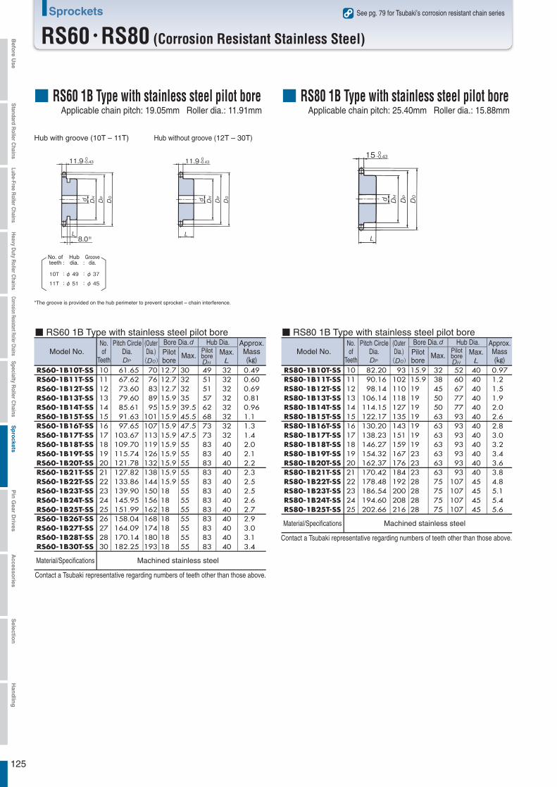
125
Sprockets
RS60・RS80 (Corrosion Resistant Stainless Steel)
■ RS60 1B Type with stainless steel pilot bore ■ RS80 1B Type with stainless steel pilot bore
See pg. 79 for Tsubaki’s corrosion resistant chain series
■ RS60 1B Type with stainless steel pilot boreApplicable chain pitch: 19.05mm Roller dia.: 11.91mm
■ RS80 1B Type with stainless steel pilot boreApplicable chain pitch: 25.40mm Roller dia.: 15.88mm
Hub without groove (12T – 30T)Hub with groove (10T – 11T)
Material/Specifications Machined stainless steel
*The groove is provided on the hub perimeter to prevent sprocket – chain interference.
10T : φ 49 :φ 3711T : φ 51 :φ 45
Material/Specifications Machined stainless steel
Contact a Tsubaki representative regarding numbers of teeth other than those above.
Contact a Tsubaki representative regarding numbers of teeth other than those above.
11.9-0.430
8.0※
11.9-0.430 15 -0.43
0
RS80-1B10T-SSRS80-1B11T-SSRS80-1B12T-SSRS80-1B13T-SSRS80-1B14T-SSRS80-1B15T-SSRS80-1B16T-SSRS80-1B17T-SSRS80-1B18T-SSRS80-1B19T-SSRS80-1B20T-SSRS80-1B21T-SSRS80-1B22T-SSRS80-1B23T-SSRS80-1B24T-SSRS80-1B25T-SS
10111213141516171819202122232425
82.20 90.16 98.14106.14114.15122.17130.20138.23146.27154.32162.37170.42178.48186.54194.60202.66
93102110118127135143151159167176184192200208216
15.915.91919191919191923232328282828
32384550506363636363636375757575
526067777793939393939393
107107107107
40404040404040404040404045454545
0.971.2 1.5 1.9 2.0 2.6 2.8 3.0 3.2 3.4 3.6 3.8 4.8 5.1 5.4 5.6
RS60-1B10T-SSRS60-1B11T-SSRS60-1B12T-SSRS60-1B13T-SSRS60-1B14T-SSRS60-1B15T-SSRS60-1B16T-SSRS60-1B17T-SSRS60-1B18T-SSRS60-1B19T-SSRS60-1B20T-SSRS60-1B21T-SSRS60-1B22T-SSRS60-1B23T-SSRS60-1B24T-SSRS60-1B25T-SSRS60-1B26T-SSRS60-1B27T-SSRS60-1B28T-SSRS60-1B30T-SS
1011121314151617181920212223242526272830
61.65 67.62 73.60 79.60 85.61 91.63 97.65103.67109.70115.74121.78127.82133.86139.90145.95151.99158.04164.09170.14182.25
70 76 83 89 95101107113119126132138144150156162168174180193
12.712.712.715.915.915.915.915.915.915.915.915.915.918181818181818
3032323539.545.547.547.5555555555555555555555555
4951515762687373838383838383838383838383
3232323232323232404040404040404040404040
0.490.600.690.810.961.1 1.3 1.4 2.0 2.1 2.2 2.3 2.5 2.5 2.6 2.7 2.9 3.0 3.1 3.4
: :Groove
dia.No. ofteeth
Hubdia.
Approx.Mass(kg)
Model No.No.of
Teeth
Pitch CircleDia.
Bore Dia.(OuterDia.) Pilot
boreMax.
Approx.Mass(kg)
Model No.No.of
Teeth
Pitch CircleDia.
(OuterDia.)
Bore Dia.Pilotbore
Max.
Hub Dia.Max.Pilot
bore
Hub Dia.Max.Pilot
bore
Befo
re Use
Standard R
oller Chains
Lube-Free Roller C
hainsH
eavy Duty R
oller Chains
Corrosion Resistant Roller ChainsS
pecialty Roller C
hainsS
pro
cketsP
in G
ear Drives
Accesso
riesS
election
Han
dlin
g

126
Sprockets
RS35 – RS60 (Corrosion Resistant Engineering Plastic)
See pg. 79 for Tsubaki’s corrosion resistant chain series
Hub without groove (14T and over)Hub with groove (13T)
Hub without groove (14T and over)Hub with groove (13T)
Hub without groove (13T and over)Hub with groove (12T)
Bold lettering indicates stock items.
■Corrosion Resistant Engineering Plastic Pilot Bore Series●Operating Conditions
N・m
● RS35 Engineering plastic pilot bore sprocket ● RS40 Engineering plastic pilot bore sprocket
● RS50 Engineering plastic pilot bore sprocket ● RS60 Engineering plastic pilot bore sprocket
4.4 -0.30
13T:φ 32:φ 28
4.4 -0.30 7.3 -0.36 0
5.8※
7.3 -0.36 0
12T:φ 40:φ 32
8.9-0.360
6.4※
8.9-0.360-0.360
13T:φ 51:φ 47
11.9-0.360-0.360
RS50-1B13T-PRS50-1B14T-PRS50-1B15T-PRS50-1B16T-PRS50-1B17T-PRS50-1B18T-PRS50-1B20T-PRS50-1B22T-PRS50-1B24T-PRS50-1B25T-PRS50-1B26T-PRS50-1B28T-PRS50-1B30T-P
13141516171820222425262830
22.824.526.227.929.631.434.838.241.843.445.248.652.2
66.34 71.34 76.35 81.37 86.39 91.42101.48111.55121.62126.66131.70141.79151.87
73 78 83 89 93 98110120130135140150161
12.712.712.712.712.712.715.915.915.915.9181818
25283032354050556060657070
51 52 57 62 67 72 80 90100100110120120
25252525252828282828282828
0.070.080.090.110.120.150.200.240.290.310.340.400.43
RS60-1B13T-PRS60-1B14T-PRS60-1B15T-PRS60-1B16T-PRS60-1B17T-PRS60-1B18T-PRS60-1B20T-PRS60-1B22T-PRS60-1B24T-PRS60-1B25T-PRS60-1B26T-PRS60-1B28T-PRS60-1B30T-P
13141516171820222425262830
41.044.147.250.353.356.562.768.975.178.381.487.693.8
79.60 85.61 91.62 97.65103.67109.71121.78133.86145.95151.99158.04170.14182.25
88 93 99107113119132144156162168180193
15.915.915.915.915.915.915.915.91818181818
30323542505260657070707070
57 62 68 73 80 85 95110120120120120120
32323232324040404040404040
0.120.140.160.190.210.300.380.510.570.590.620.650.70
RS35-1B13T-PRS35-1B14T-PRS35-1B15T-PRS35-1B16T-PRS35-1B17T-PRS35-1B18T-PRS35-1B20T-PRS35-1B22T-PRS35-1B24T-PRS35-1B25T-PRS35-1B26T-PRS35-1B28T-PRS35-1B30T-P
13141516171820222425262830
5.30 5.69 6.08 6.47 6.86 7.26 8.04 8.83 9.7110.1 10.5 11.3 12.1
39.8042.8045.8148.8251.8454.8560.8966.9372.9776.0079.0285.0791.12
44465153576066727881839096
9.5 9.5 9.5 9.5 9.512.712.712.712.712.712.712.712.7
14151719222227283232354042
32303537414450535353535353
20202020202020202222222222
0.020.020.020.030.030.040.050.060.080.080.090.100.12
RS40-1B12T-PRS40-1B13T-PRS40-1B14T-PRS40-1B15T-PRS40-1B16T-PRS40-1B17T-PRS40-1B18T-PRS40-1B20T-PRS40-1B22T-PRS40-1B24T-PRS40-1B25T-PRS40-1B26T-PRS40-1B28T-PRS40-1B30T-P
1213141516171820222425262830
10.811.712.613.414.315.316.217.919.621.522.423.225.026.8
49.07 53.07 57.07 61.08 65.10 69.12 73.1481.18
89.24 97.30
101.33105.36113.43121.50
53 58 63 67 71 75 78 88 96104108112120128
9.512.712.712.712.712.712.712.712.712.712.712.712.712.7
1618222527283035425050525560
40 37 42 46 50 54 57 67 75 80 80 85 90100
2222222222222225252525252525
0.030.040.040.050.060.070.080.110.140.160.170.180.210.26
Operating temperature : -10℃ to 60℃Permiss ib le speed : Recommended at a circumferential speed of 70m/min or below (lube-free operation) (Can be used up to 150m/min in lubed or pre-lubed operation.)Mater ia l : Special MC901 nylon (dark blue)
Approx.Mass(kg)
Model No.No.of
Teeth
PitchCircleDia.
AllowableTransmission
Torque
(OuterDia.)
Bore Dia.
Pilotbore
Max.
Hub Dia.
Max.Pilotbore
N・m
Approx.Mass(kg)
Model No.No.of
Teeth
PitchCircleDia.
AllowableTransmission
Torque
(OuterDia.)
Bore Dia.
Pilotbore
Max.
Hub Dia.
Max.Pilotbore
Bold lettering indicates stock items.
: :Groove
dia.No. ofteeth
Hubdia. : :
Groovedia.
No. ofteeth
Hubdia.
: :Groove
dia.No. ofteeth
Hubdia.
N・m
Approx.Mass(kg)
Model No.No.of
Teeth
PitchCircleDia.
AllowableTransmission
Torque
(OuterDia.)
Bore Dia.
Pilotbore
Max.
Hub Dia.
Max.Pilotbore
N・m
Approx.Mass(kg)
Model No.No.of
Teeth
PitchCircleDia.
AllowableTransmission
Torque
(OuterDia.)
Bore Dia.
Pilotbore
Max.
Hub Dia.
Max.Pilotbore
Befo
re Use
Standard R
oller Chains
Lube-Free Roller C
hainsH
eavy Duty R
oller Chains
Corrosion Resistant Roller ChainsS
pecialty Roller C
hainsS
pro
cketsP
in G
ear Drives
Accesso
riesS
election
Han
dlin
g
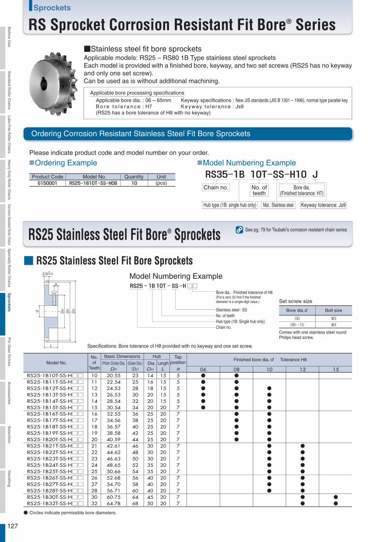
RS25 Stainless Steel Fit Bore® Sprockets See pg. 79 for Tsubaki’s corrosion resistant chain series
127
Sprockets
RS Sprocket Corrosion Resistant Fit Bore® Series■Stainless steel fit bore sprockets
Applicable bore processing specifications
Quantity Unit(pcs)
■Model Numbering Example
Chain no. No. ofteeth
Hub type (1B: single hub only) Mat.: Stainless steel
Bore dia.(Finished tolerance: H7)
Keyway tolerance: Js9
2.9 0-0.25
Model No.No.of
Teeth
Basic Dimensions Hub Tapposition
Finished bore dia. Tolerance H8Pitch Circle Dia. (Outer Dia.)
)Dia. Length
~
Set screw size
Comes with one stainless steel round Philips head screw.
□□
●●●●●●●●●●●
●●●●●●
06 08 10 12 15
●●●●●●●●●●●●●●●●●
●●●●●●●●●●
●●
RS25-1B10T-SS-H□□RS25-1B11T-SS-H□□RS25-1B12T-SS-H□□RS25-1B13T-SS-H□□RS25-1B14T-SS-H□□RS25-1B15T-SS-H□□RS25-1B16T-SS-H□□RS25-1B17T-SS-H□□RS25-1B18T-SS-H□□RS25-1B19T-SS-H□□RS25-1B20T-SS-H□□RS25-1B21T-SS-H□□RS25-1B22T-SS-H□□RS25-1B23T-SS-H□□RS25-1B24T-SS-H□□RS25-1B25T-SS-H□□RS25-1B26T-SS-H□□RS25-1B27T-SS-H□□RS25-1B28T-SS-H□□RS25-1B30T-SS-H□□RS25-1B32T-SS-H□□
101112131415161718192021222324252627283032
20.5522.5424.5326.5328.5430.5432.5534.5636.5738.5840.5942.6144.6246.6348.6550.6652.6854.7056.7160.7564.78
232528303234363840424446485052545658606468
141618202020252525252530303035354040404550
151515151520202020202020202020202020202020
555557777777777777777
● Circles indicate permissible bore diameters.
Applicable models: RS25 – RS80 1B Type stainless steel sprocketsEach model is provided with a finished bore, keyway, and two set screws (RS25 has no keyway and only one set screw).Can be used as is without additional machining.
Applicable bore dia. : 06 – 65mmB o r e t o l e r a n c e : H7(RS25 has a bore tolerance of H8 with no keyway)
Keyway specifications : New JIS standards (JIS B 1301 – 1996), normal type parallel keyKeyway to le rance : Js9
Ordering Corrosion Resistant Stainless Steel Fit Bore Sprockets
Please indicate product code and model number on your order.
■ RS25 Stainless Steel Fit Bore Sprockets
■Ordering Example
Product Code Model No.
Model Numbering Example
Bore dia. : Finished tolerance of H8(Put a zero (0) first if the finisheddiameter is a single-digit value.)
Stainless steel : SSNo. of teethHub type (1B: Single hub only)Chain no.
Bolt sizeBore dia.
Specifications: Bore tolerance of H8 provided with no keyway and one set screw.
Befo
re Use
Standard R
oller Chains
Lube-Free Roller C
hainsH
eavy Duty R
oller Chains
Corrosion Resistant Roller ChainsS
pecialty Roller C
hainsS
pro
cketsP
in G
ear Drives
Accesso
riesS
election
Han
dlin
g

128
Sprockets
RS35 Stainless Steel Fit Bore® SprocketsSee pg. 79 for Tsubaki’s corrosion resistant chain series
Applicable Bore Dia.KeywayWidthKW
Tolerance
(Js9)
KeywayDepthKH
ToleranceSet Screw Size
MX
□□
2-MX
90°
KWa4.4
4.8※
0-0.30
KH
2-MX
90°
KWa4.4
0-0.30
KH
10T : φ 25 :φ 1811T : φ 27 :φ 2212T : φ 31 :φ 2413T : φ 32 :φ 28
Model Numbering Example
*The groove is provided on the hub perimeter to prevent sprocket – chain interference.
●●●●●●●
●●●●●●●●
●●●●●●●●●●●●●●
●●●●●●●●●●●●●●●●●●
●●●●●●●●●●●●●●●●●●
●
●●●●●●●●●●●●●●●
●
●●●●●●●●●●●●●●●
●●●●●●●●●●●●●●●
●●●●●●●●●●●●●●
●●●●●●●●●●●●●
●●●●●●●○○○○○○
●●●●●○○○○○○
●●●●●○○○○○○
●●●●○○○○○○
●●●○○○○○○
1011121314151617181920212223242526272830
RS35-1B10T-SS-H□□JRS35-1B11T-SS-H□□JRS35-1B12T-SS-H□□JRS35-1B13T-SS-H□□JRS35-1B14T-SS-H□□JRS35-1B15T-SS-H□□JRS35-1B16T-SS-H□□JRS35-1B17T-SS-H□□JRS35-1B18T-SS-H□□JRS35-1B19T-SS-H□□JRS35-1B20T-SS-H□□JRS35-1B21T-SS-H□□JRS35-1B22T-SS-H□□JRS35-1B23T-SS-H□□JRS35-1B24T-SS-H□□JRS35-1B25T-SS-H□□JRS35-1B26T-SS-H□□JRS35-1B27T-SS-H□□JRS35-1B28T-SS-H□□JRS35-1B30T-SS-H□□J
30.8233.8136.8039.8042.8145.8148.8251.8454.8557.8760.8963.9166.9369.9572.9776.0079.0282.0585.0791.12
3538414447515457606366697275788184879096
2527313230353741444750535353535353535353
2020202020202020202020202020222222222222
55558888888888
10/7※
10/7※
10/7※
10/7※
10/7※
10/7※
10 12 14 15 16 17 18 19 20 22 24 25 28 30 32
● circles indicate applicable bore diameters. circles indicate that the tap position is at 7mm for applicable bore diameters.
10 and up to 12More than 12 and up to 17More than 17 and up to 22More than 22 and up to 30More than 30 and up to 38More than 38 and up to 44More than 44 and up to 50More than 50 and up to 58More than 58 and up to 65
Provided with two stainless steel set screws.
Keyway tolerance (Js9)Bore dia.Bore tolerance (H7)Stainless steel : SSNo of teethTypeChain no.
Model No.No.of
Teeth
Basic Dimensions Hub Tapposition
Finished bore dia. Tolerance H7Pitch Circle Dia. (Outer Dia.)
)Dia. Length
: :Groove
dia.No. ofteeth
Hubdia.
■ RS35 Stainless Steel Fit Bore SprocketsApplicable chain pitch: 9.525mm Roller dia.: 5.08mm
Hub without groove (14T and over)Hub with groove (10T – 13T)
Befo
re Use
Standard R
oller Chains
Lube-Free Roller C
hainsH
eavy Duty R
oller Chains
Corrosion Resistant Roller ChainsS
pecialty Roller C
hainsS
pro
cketsP
in G
ear Drives
Accesso
riesS
election
Han
dlin
g
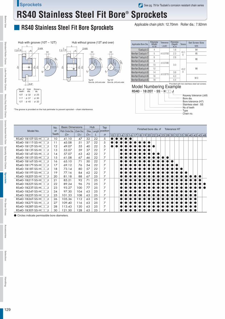
129
Sprockets
RS40 Stainless Steel Fit Bore® SprocketsSee pg. 79 for Tsubaki’s corrosion resistant chain series
Model Numbering ExampleProvided with two stainless steel set screws.
Keyway tolerance (Js9)Bore dia.Bore tolerance (H7)Stainless steel : SSNo of teethTypeChain no.
: :Groove
dia.No. ofteeth
Hubdia.
■ RS40 Stainless Steel Fit Bore SprocketsApplicable chain pitch: 12.70mm Roller dia.: 7.92mm
Hub without groove (13T and over)Hub with groove (10T – 12T)
□□
2-MX
90°
KWa7.3
5.8※
0-0.36
KH
2-MXa7.3
Tap 120°Bore dia. φ40 and under
0-0.36
KH
90°
KW
KHKH 120
°
KW
KHKH
*The groove is provided on the hub perimeter to prevent sprocket – chain interference.
10T : φ 32 :φ 2511T : φ 37 :φ 3012T : φ 40 :φ 32
●●●
●●●●●●●●●●●●●●●●●●●●
●●●●●●●●●●●●●●●●●●●●
●●●●●●●●●●●●●●●●●●●●
●●●●●●●●●●●●●●●●●●●
●●●●●●●●●●●●●●●●●●●
●●●●●●●●●●●●●●●●●●●
●●●●●●●●●●●●●●●●●●●
●
●●●●●●●●●●●●●●●●
●●●●●●●●●●●●●●●●
●●●●●●●●●●●●●●●
●●●●●●●●●●●●●●●
●●●●●●●●●●●●●●
●●●●●●●●●●●●●
●●●●●●●●●●●●
●●●●●●●●●●●
●●●●●●●●●●
●●●●●●●●●●
●●●●●●
RS40-1B10T-SS-H□□JRS40-1B11T-SS-H□□JRS40-1B12T-SS-H□□JRS40-1B13T-SS-H□□JRS40-1B14T-SS-H□□JRS40-1B15T-SS-H□□JRS40-1B16T-SS-H□□JRS40-1B17T-SS-H□□JRS40-1B18T-SS-H□□JRS40-1B19T-SS-H□□JRS40-1B20T-SS-H□□JRS40-1B21T-SS-H□□JRS40-1B22T-SS-H□□JRS40-1B23T-SS-H□□JRS40-1B24T-SS-H□□JRS40-1B25T-SS-H□□JRS40-1B26T-SS-H□□JRS40-1B27T-SS-H□□JRS40-1B28T-SS-H□□JRS40-1B30T-SS-H□□J
1011121314151617181920212223242526272830
41.10 45.08 49.07 53.07 57.07 61.08 65.10 69.12 73.14 77.16 81.18 85.21 89.24 93.27 97.30101.33105.36109.40113.43121.50
47 51 55 59 63 67 71 76 80 84 88 92 96100104108112116120128
3237403742465054576267717577636363636363
2222222222222222222225252525252525252525
55577777777777777777
● Circles indicate permissible bore diameters.
●●●
10 12 14 15 16 17 18 19 20 22 24 25 28 30 32 35 38 40 42 45 48
Applicable Bore Dia.KeywayWidthKW
Tolerance
(Js9)
KeywayDepthKH
ToleranceSet Screw Size
MX
10 and up to 12More than 12 and up to 17More than 17 and up to 22More than 22 and up to 30More than 30 and up to 38More than 38 and up to 44More than 44 and up to 50More than 50 and up to 58More than 58 and up to 65
Model No.No.of
Teeth
Basic Dimensions Hub Tapposition
Finished bore dia. Tolerance H7Pitch Circle Dia. (Outer Dia.)
)Dia. Length
Tap 90°Bore dia. φ40 and under
Befo
re Use
Standard R
oller Chains
Lube-Free Roller C
hainsH
eavy Duty R
oller Chains
Corrosion Resistant Roller ChainsS
pecialty Roller C
hainsS
pro
cketsP
in G
ear Drives
Accesso
riesS
election
Han
dlin
g

130
Sprockets
RS50 Stainless Steel Fit Bore® SprocketsSee pg. 79 for Tsubaki’s corrosion resistant chain series
Model Numbering Example
Provided with two stainless steel set screws.
Keyway tolerance (Js9)Bore dia.Bore tolerance (H7)Stainless steel : SSNo of teethTypeChain no.
■ RS50 Stainless Steel Fit Bore SprocketsApplicable chain pitch: 15.875mm Roller dia.: 10.16mm
Hub without groove (14T and over)Hub with groove (10T – 13T)
□□
2-MXa8.9
0-0.36
120°
KW
KH
2-MX
90°
KWa8.9
6.4※
0-0.36
KH
90°
KW
KH
*The groove is provided on the hub perimeter to prevent sprocket – chain interference.
10T : φ 40 :φ 3211T : φ 46 :φ 3712T : φ 51 :φ 4213T : φ 51 :φ 47
● ● ●●●●●●●●●
●●●●●●●●●
●●●●●●●●●
●●●●●●●●●●●●●●●●
●●●●●●●●●●●●●●●●
●●●●●●●●●●●●●●●●●●●●
●●●●●●●●●●●●●●●●●●●●
●●●●●●●●●●●●●●●●●●●●
●●●●●●●●●●●●●●●●●●●
●●●●●●●●●●●●●●●●●●●
●●●●●●●●●●●●●●●●●●
●●●●●●●●●●●●●●●●●●
●●●●●●●●●●●●●●●●●●
●●●●●●●●●●●●●●●
●●●●●●●●●●●●●●
●●●●●●●●●●●●●●
●●●●●●●●●●●●●
●●●●●●●●●●●●●
●●●●
RS50-1B10T-SS-H□□JRS50-1B11T-SS-H□□JRS50-1B12T-SS-H□□JRS50-1B13T-SS-H□□JRS50-1B14T-SS-H□□JRS50-1B15T-SS-H□□JRS50-1B16T-SS-H□□JRS50-1B17T-SS-H□□JRS50-1B18T-SS-H□□JRS50-1B19T-SS-H□□JRS50-1B20T-SS-H□□JRS50-1B21T-SS-H□□JRS50-1B22T-SS-H□□JRS50-1B23T-SS-H□□JRS50-1B24T-SS-H□□JRS50-1B25T-SS-H□□JRS50-1B26T-SS-H□□JRS50-1B27T-SS-H□□JRS50-1B28T-SS-H□□JRS50-1B30T-SS-H□□J
1011121314151617181920212223242526272830
51.37 56.35 61.34 66.34 71.34 76.35 81.37 86.39 91.41 96.45101.48106.51111.55116.58121.62126.66131.70136.74141.79151.87
58 64 69 74 79 84 89 94100105110115120125130135140145150161
4046515152576267727373737373737373737373
2525252525252525282828282828282828282828
66667777888888888888
● circles indicate applicable bore diameters.
10 12 14 15 16 17 18 19 20 22 24 25 28 30 32 35 38 40 42 45 48
Tap 120°Bore dia. φ40 and under
Tap 90°Bore dia. φ40 and under
Applicable Bore Dia.KeywayWidthKW
Tolerance
(Js9)
KeywayDepthKH
ToleranceSet Screw Size
MX
10 and up to 12More than 12 and up to 17More than 17 and up to 22More than 22 and up to 30More than 30 and up to 38More than 38 and up to 44More than 44 and up to 50More than 50 and up to 58More than 58 and up to 65
: :Groove
dia.No. ofteeth
Hubdia.
Model No.No.of
Teeth
Basic Dimensions Hub Tapposition
Finished bore dia. Tolerance H7Pitch Circle Dia. (Outer Dia.)
)Dia. Length
Befo
re Use
Standard R
oller Chains
Lube-Free Roller C
hainsH
eavy Duty R
oller Chains
Corrosion Resistant Roller ChainsS
pecialty Roller C
hainsS
pro
cketsP
in G
ear Drives
Accesso
riesS
election
Han
dlin
g
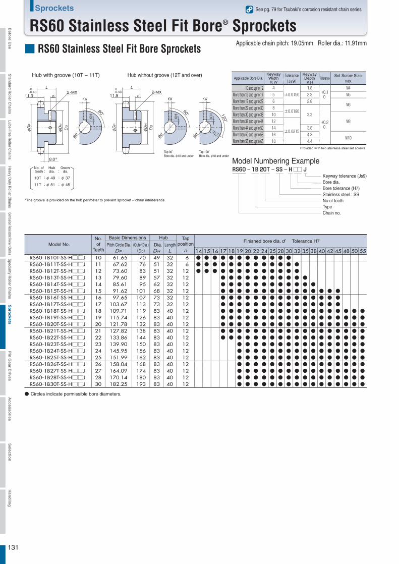
131
Sprockets
RS60 Stainless Steel Fit Bore® SprocketsSee pg. 79 for Tsubaki’s corrosion resistant chain series
Model Numbering Example
Keyway tolerance (Js9)Bore dia.Bore tolerance (H7)Stainless steel : SSNo of teethTypeChain no.
■ RS60 Stainless Steel Fit Bore SprocketsApplicable chain pitch: 19.05mm Roller dia.: 11.91mm
Hub without groove (12T and over)Hub with groove (10T – 11T)
Tap 120°Bore dia. φ40 and under
Tap 90°Bore dia. φ40 and under
□□
2-MXa11.9
0-0.43
φ φ
120°
KW
φ
KH
2-MX
90°
KWa11.9
8.0※
0-0.43
φ φ
φ
KH
90°
KW
φ
KH
*The groove is provided on the hub perimeter to prevent sprocket – chain interference.
10T : φ 49 :φ 3711T : φ 51 :φ 45
●●●
●●●
●●●
●●●●●●●●●●●●●
●●●●●●●●●●●●●
●●●●●●●●●●●●●●●●●●●●
●●●●●●●●●●●●●●●●●●●●
●●●●●●●●●●●●●●●●●●●●
●●●●●●●●●●●●●●●●●●●●
●●●●●●●●●●●●●●●●●●●●
●●●●●●●●●●●●●●●●●●●●
●●●●●●●●●●●●●●●●●●●●
●●●●●●●●●●●●●●●●●●●
●●●●●●●●●●●●●●●●●
●●●●●●●●●●●●●●●●
●●●●●●●●●●●●●●●
●●●●●●●●●●●●●●●
●●●●●●●●●●●●●●●
●●●●●●●●●●●●
●●●●●●●●●●●●
●●●●●●●●●●●●
RS60-1B10T-SS-H□□JRS60-1B11T-SS-H□□JRS60-1B12T-SS-H□□JRS60-1B13T-SS-H□□JRS60-1B14T-SS-H□□JRS60-1B15T-SS-H□□JRS60-1B16T-SS-H□□JRS60-1B17T-SS-H□□JRS60-1B18T-SS-H□□JRS60-1B19T-SS-H□□JRS60-1B20T-SS-H□□JRS60-1B21T-SS-H□□JRS60-1B22T-SS-H□□JRS60-1B23T-SS-H□□JRS60-1B24T-SS-H□□JRS60-1B25T-SS-H□□JRS60-1B26T-SS-H□□JRS60-1B27T-SS-H□□JRS60-1B28T-SS-H□□JRS60-1B30T-SS-H□□J
1011121314151617181920212223242526272830
61.65 67.62 73.60 79.60 85.61 91.62 97.65103.67109.71115.74121.78127.82133.86139.90145.95151.99158.04164.09170.14182.25
70 76 83 89 95101107113119126132138144150156162168174180193
4951515762687373838383838383838383838383
3232323232323232404040404040404040404040
6 6121212121212121212121212121212121212
● Circles indicate permissible bore diameters.
14 15 16 17 18 19 20 22 24 25 28 30 32 35 38 40 42 45 48 50 55
Provided with two stainless steel set screws.
Applicable Bore Dia.KeywayWidthKW
Tolerance
(Js9)
KeywayDepthKH
ToleranceSet Screw Size
MX
10 and up to 12More than 12 and up to 17More than 17 and up to 22More than 22 and up to 30More than 30 and up to 38More than 38 and up to 44More than 44 and up to 50More than 50 and up to 58More than 58 and up to 65
: :Groove
dia.No. ofteeth
Hubdia.
Model No.No.of
Teeth
Basic Dimensions Hub Tapposition
Finished bore dia. Tolerance H7Pitch Circle Dia. (Outer Dia.)
)Dia. Length
Befo
re Use
Standard R
oller Chains
Lube-Free Roller C
hainsH
eavy Duty R
oller Chains
Corrosion Resistant Roller ChainsS
pecialty Roller C
hainsS
pro
cketsP
in G
ear Drives
Accesso
riesS
election
Han
dlin
g
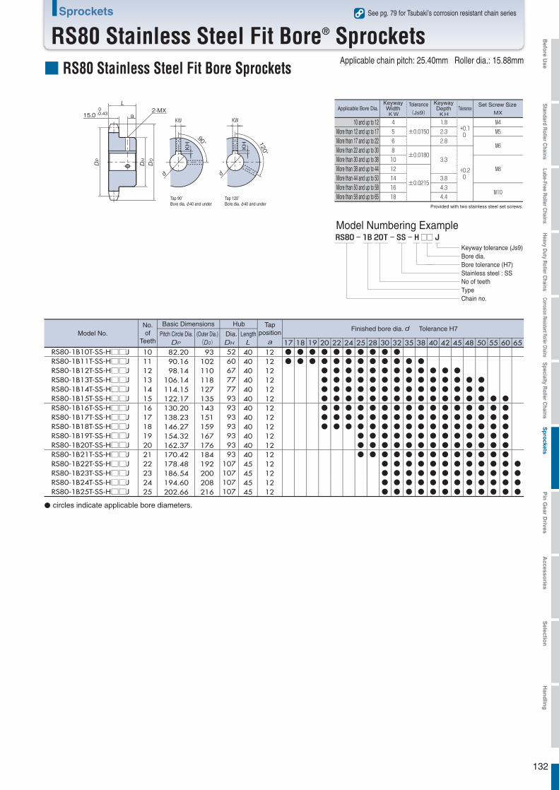
132
Sprockets
RS80 Stainless Steel Fit Bore® SprocketsSee pg. 79 for Tsubaki’s corrosion resistant chain series
Model Numbering Example
Keyway tolerance (Js9)Bore dia.Bore tolerance (H7)Stainless steel : SSNo of teethTypeChain no.
■ RS80 Stainless Steel Fit Bore SprocketsApplicable chain pitch: 25.40mm Roller dia.: 15.88mm
Tap 120°Bore dia. φ40 and under
Tap 90°Bore dia. φ40 and under
□□
2-MXa15.0
0-0.43
120°
KW
KH
90°
KW
KH
●●●●●●●●●●●●●●●
●●●●●●●●●
●●●●●●●●●
●●●●●●●●●●●●
●●●●●●●●●●●●
●●●●●●●●●●●●●●●●
●●●●●●●●●●●●●●●●
●●●●●●●●●●●●●●●
●●●●●●●●●●●●●●●
●●●●●●●●●●●●●●
●●●●●●●●●●●●●●
●●●●●●●●●●●●●●
●●●●●●●●●●●●●
●●●●●●●●●●●●●
●●●●●●●●●●●
●●●●●●●●●●●
●●●●
RS80-1B10T-SS-H□□JRS80-1B11T-SS-H□□JRS80-1B12T-SS-H□□JRS80-1B13T-SS-H□□JRS80-1B14T-SS-H□□JRS80-1B15T-SS-H□□JRS80-1B16T-SS-H□□JRS80-1B17T-SS-H□□JRS80-1B18T-SS-H□□JRS80-1B19T-SS-H□□JRS80-1B20T-SS-H□□JRS80-1B21T-SS-H□□JRS80-1B22T-SS-H□□JRS80-1B23T-SS-H□□JRS80-1B24T-SS-H□□JRS80-1B25T-SS-H□□J
10111213141516171819202122232425
82.20 90.16 98.14106.14114.15122.17130.20138.23146.27154.32162.37170.42178.48186.54194.60202.66
93102110118127135143151159167176184192200208216
52 60 67 77 77 93 93 93 93 93 93 93107107107107
40404040404040404040404045454545
12121212121212121212121212121212
17 18 19 20 22 24 25 28 30 32 35 38 40 42 45 48 50 55 60 65
Provided with two stainless steel set screws.
Applicable Bore Dia.KeywayWidthKW
Tolerance
(Js9)
KeywayDepthKH
ToleranceSet Screw Size
MX
10 and up to 12More than 12 and up to 17More than 17 and up to 22More than 22 and up to 30More than 30 and up to 38More than 38 and up to 44More than 44 and up to 50More than 50 and up to 58More than 58 and up to 65
● circles indicate applicable bore diameters.
Model No.No.of
Teeth
Basic Dimensions Hub Tapposition
Finished bore dia. Tolerance H7Pitch Circle Dia. (Outer Dia.)
)Dia. Length
Befo
re Use
Standard R
oller Chains
Lube-Free Roller C
hainsH
eavy Duty R
oller Chains
Corrosion Resistant Roller ChainsS
pecialty Roller C
hainsS
pro
cketsP
in G
ear Drives
Accesso
riesS
election
Han
dlin
g
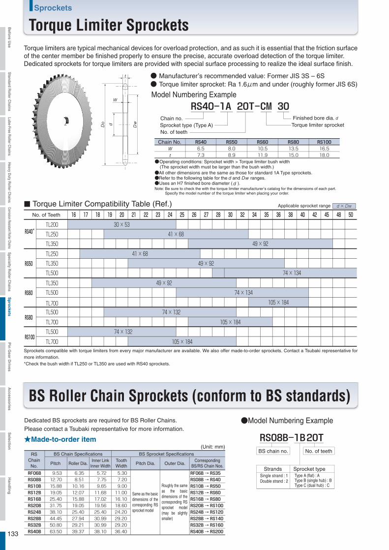
133
Sprockets
Torque Limiter Sprockets
Chain no.Sprocket type (Type A)No. of teeth
Torque limiter sprocketFinished bore dia.
●All other dimensions are the same as those for standard 1A Type sprockets.●Refer to the following table for the and ranges.●Uses an H7 finished bore diameter ( ).
●Operating conditions: Sprocket width > Torque limiter bush width (The sprocket width must be larger than the bush width.)
● Manufacturer’s recommended value: Former JIS 3S – 6S● Torque limiter sprocket: Ra 1.6μm and under (roughly former JIS 6S)
..
..
..
Model Numbering Example
●Model Numbering Example
No. of teeth
Sprocket typeStrands
RSChainNo.
BS Chain Specifications BS Sprocket Specifications
Pitch Roller Dia.Inner Link
Inner WidthToothWidth Pitch Dia. Outer Dia.
CorrespondingBS/RS Chain Nos.
→→→→→→→→→→
■ Torque Limiter Compatibility Table (Ref.)
BS Roller Chain Sprockets (conform to BS standards)
××
××
××
×
××
×
××
×
Torque limiters are typical mechanical devices for overload protection, and as such it is essential that the friction surface of the center member be finished properly to ensure the precise, accurate overload detection of the torque limiter.Dedicated sprockets for torque limiters are provided with special surface processing to realize the ideal surface finish.
Chain No.
Note: Be sure to check the with the torque limiter manufacturer’s catalog for the dimensions of each part. Specify the model number of the torque limiter when placing your order.
Applicable sprocket range
No. of Teeth
*
Sprockets compatible with torque limiters from every major manufacturer are available. We also offer made-to-order sprockets. Contact a Tsubaki representative for more information.*Check the bush width if TL250 or TL350 are used with RS40 sprockets.
Dedicated BS sprockets are required for BS Roller Chains.Please contact a Tsubaki representative for more information.
★Made-to-order item(Unit: mm)
Same as the basic dimensions of the corresponding RS sprocket model
Roughly the same as the basic dimensions of the corresponding RS sprocket model (may be slightly smaller)
BS chain no.
Type A (flat) : AType B (single hub) : BType C (dual hub) : C
Single strand : 1Double strand : 2
Befo
re Use
Standard R
oller Chains
Lube-Free Roller C
hainsH
eavy Duty R
oller Chains
Corrosion Resistant Roller ChainsS
pecialty Roller C
hainsS
pro
cketsP
in G
ear Drives
Accesso
riesS
election
Han
dlin
g
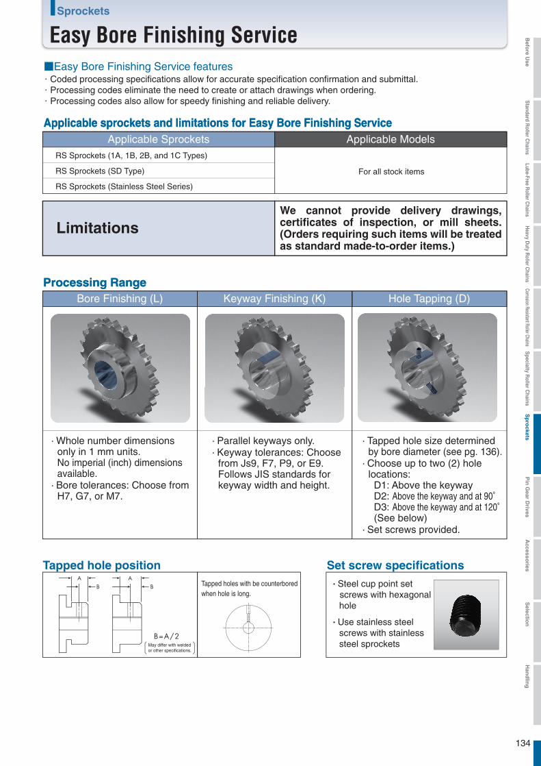
134
Sprockets
Easy Bore Finishing Service
Applicable Sprockets Applicable Models
Applicable sprockets and limitations for Easy Bore Finishing ServiceApplicable sprockets and limitations for Easy Bore Finishing Service
For all stock items
Bore Finishing (L) Keyway Finishing (K) Hole Tapping (D)Processing RangeProcessing Range
Tapped hole position Set screw specifications・Steel cup point set screws with hexagonal hole
・Use stainless steel screws with stainless steel sprockets
AB
AB
B=A/2
■Easy Bore Finishing Service features・Coded processing specifications allow for accurate specification confirmation and submittal.・Processing codes eliminate the need to create or attach drawings when ordering.・Processing codes also allow for speedy finishing and reliable delivery.
RS Sprockets (1A, 1B, 2B, and 1C Types)
RS Sprockets (SD Type)
RS Sprockets (Stainless Steel Series)
LimitationsWe cannot provide delivery drawings, certificates of inspection, or mill sheets. (Orders requiring such items will be treated as standard made-to-order items.)
・Parallel keyways only.・Keyway tolerances: Choose from Js9, F7, P9, or E9. Follows JIS standards for keyway width and height.
・Tapped hole size determined by bore diameter (see pg. 136).・Choose up to two (2) hole locations: D1: Above the keyway D2: Above the keyway and at 90° D3: Above the keyway and at 120° (See below)・Set screws provided.
・Whole number dimensions only in 1 mm units. No imperial (inch) dimensions available.・Bore tolerances: Choose from H7, G7, or M7.
May differ with weldedor other specifications.
Tapped holes with be counterbored when hole is long.
Befo
re Use
Standard R
oller Chains
Lube-Free Roller C
hainsH
eavy Duty R
oller Chains
Corrosion Resistant Roller ChainsS
pecialty Roller C
hainsS
pro
cketsP
in G
ear Drives
Accesso
riesS
election
Han
dlin
g

135
Sprockets
Easy Bore Finishing Service
List of Applicable Sprockets for Easy Bore Finishing Service
●
●
●
●
●
●
●
●
●
●
●
●
●
●
●
●
●
●
●
●
●
●
●
●
●
●
●
○
○
○
○
○
○
○
○
○
◎
◎
◎
◎
◎
◎
◎
◎
◎
◎
◎
◎
◎
◎
◎
◎
◎
◎
◎
◎
◎
◎
◎
◎
◎
◎
◎
◎
◎
◎
◎
◎
◎
●
●
●
●
●
●
●
●
●
●
●
●
●
●
●
●
●
●
●
●
●
●
●
●
●
●
●
○
○
○
○
○
○
○
○
○
○
○
○
○
○
○
○
○
○
○
○
○
◎
◎
◎
◎
◎
◎
◎
◎
◎
◎
◎
◎
◎
◎
◎
◎
◎
◎
◎
◎
◎
◎
◎
◎
◎
◎
◎
◎
◎
◎
◎
◎
◎
●
●
●
●
●
●
●
●
●
●
●
●
●
●
●
●
●
●
●
●
●
●
●
●
◎
◎
◎
○
○
○
○
○
○
○
○
○
○
○
○
○
○
○
○
○
○
○
○
○
◎
◎
◎
◎
◎
◎
◎
◎
◎
◎
◎
◎
◎
◎
◎
◎
◎
◎
◎
◎
◎
◎
◎
◎
◎
◎
◎
◎
◎
◎
◎
◎
◎
●
●
●
●
●
●
●
●
●
●
●
●
●
●
●
●
●
●
●
●
●
○
○
○
○
○
○
○
○
○
○
○
○
○
○
○
◎
◎
○
○
○
○
○
○
○
○
○
○
○
○
○
○
○
◎
◎
◎
◎
◎
◎
◎
◎
◎
◎
◎
◎
◎
◎
◎
◎
◎
◎
◎
◎
◎
◎
◎
◎
◎
◎
◎
◎
◎
◎
◎
◎
◎
●
●
●
●
●
●
●
●
●
●
●
●
●
◎
◎
◎
◎
◎
◎
◎
◎
◎
◎
◎
◎
◎
◎
◎
◎
◎
◎
◎
◎
◎
◎
◎
○
○
○
○
○
○
○
○
○
○
○
○
○
○
○
○
○
○
○
○
○
○
○
◎
◎
◎
◎
◎
◎
◎
◎
◎
◎
◎
◎
◎
◎
◎
◎
◎
◎
◎
◎
◎
◎
◎
◎
◎
◎
◎
◎
●
●
●
●
●
●
●
●
●
●
●
●
○
○
○
○
○
○
○
○
○
○
○
○
○
○
○
○
◎
●
◎
◎
◎
●
◎
◎
○
○
○
○
○
○
○
○
○
○
◎
◎
◎
◎
◎
◎
◎
◎
◎
◎
●
●
●
●
●
●
●
●
●
●
●
●
○
○
○
○
○
○
○
○
○
○
○
○
●
●
●
●
●
●
●
●
●
●
●
●
●
●
●
●
○
○
○
○
○
●
●
●
●
●
●
●
●
●
●
●
●
●
●
○
○
○
○
○
○
○
●
●
●
●
●
●
●
●
●
●
●
○
○
○
○
○
○
○
○
○
○
●
●
●
●
●
●
○
○
○
○
○
○
○
○
○
○
○
○
○
○
○
●
●
●
○
○
○
○
○
○
○
○
○
○
○
○
●
●
○
○
○
○
○
○
○
○
○
○
○
●
●
●
●
●
●
●
●
●
●
●
●
●
●
●
●
●
●
●
●
●
●
●
●
●
●
●
●
●
●
●
●
●
●
●
●
●
●
●
●
●
●
●
●
●
●
●
●
●
○
○
○
○
○
○
○
○
○
○
○
○
○
○
○
○
○
○
○
○
○
○
○
○
○
○
○
○
○
○
○
○
○
○
○
○
○
○
○
○
○
○
○
○
○
○
○
○
○
○
○
○
○
○
○
○
○
○
○
○
○
○
○
○
○
○
○
○
○
○
○
○
○
○
○
○
○
○
○
○
○
○
○
○
○
○
○
○
○
○
○
○
○
○
○
○
○
○
○
○
○
○
○
○
○
○
○
○
○
○
○
○
○
○
○
○
○
○
○
○
○
○
○
○
○
○
○
○
○
○
○
○
○
○
○
○
○
○
○
○
9
10
11
12
13
14
15
16
17
18
19
20
21
22
23
24
25
26
27
28
30
32
34
35
36
38
40
42
45
48
50
54
60
65
70
75
35
B
●
●
●
●
●
●
●
●
●
●
●
●
○
○
○
○
○
○
○
140
B
●
●
●
●
●
●
●
●
●
●
●
●
○
○
○
○
○
○
160
BA
40
B C A
50
B C A
60
B C A
80
B C A
100
B
40
B
50
B
60
B
80
B
40
B
50
B
25
B
35
B
60
B
80
B40 50 60 80
100
B
120
BA B
120
C
RS Sprockets (●: Hardened teeth, ○ : Standard teeth, ◎ : Both)
Spr
ocke
t Mod
el /
No.
of T
eeth
Steel
Single Strand Double Strand SD Type Single Strand Type
Stainless Steel
*Note
Note: Processing fee for boxes colored blue in the thick outlined area is relatively high.
Befo
re Use
Standard R
oller Chains
Lube-Free Roller C
hainsH
eavy Duty R
oller Chains
Corrosion Resistant Roller ChainsS
pecialty Roller C
hainsS
pro
cketsP
in G
ear Drives
Accesso
riesS
election
Han
dlin
g
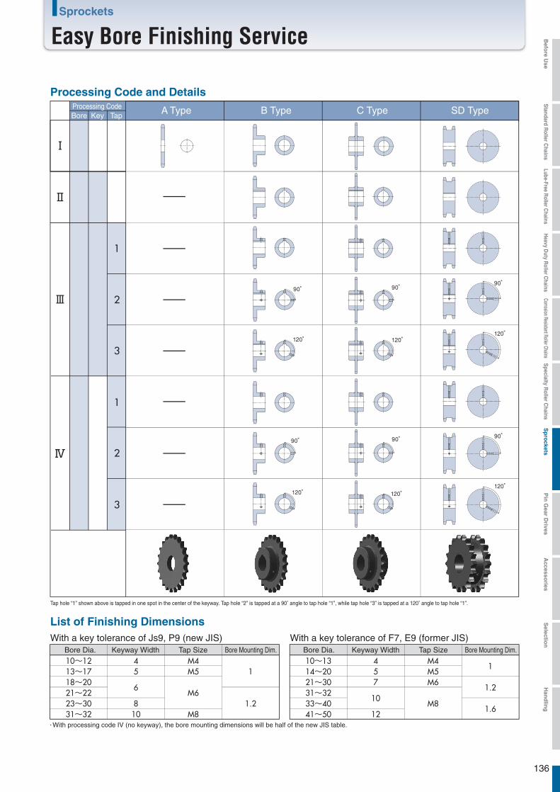
136
Sprockets
Easy Bore Finishing Service
Processing CodeBore Key Tap
Ⅰ
1
2
3
1
2
3
Ⅲ
Ⅳ
Ⅱ
・With processing code IV (no keyway), the bore mounting dimensions will be half of the new JIS table.
List of Finishing Dimensions
Bore Dia.
10~1213~1718~2021~2223~3031~32
Keyway Width
45
6
810
Tap Size
M4M5
M6
M8
Bore Mounting Dim.
1
1.2
With a key tolerance of F7, E9 (former JIS)Bore Dia.
10~1314~2021~3031~3233~4041~50
Keyway Width
457
10
12
Tap Size
M4M5M6
M8
Bore Mounting Dim.
1
1.2
1.6
90°
120°
90°
120°
90°
120°
90°
120°
90°
120°
120°
90°
Processing Code and Details
A Type B Type C Type SD Type
Tap hole “1” shown above is tapped in one spot in the center of the keyway. Tap hole “2” is tapped at a 90° angle to tap hole “1”, while tap hole “3” is tapped at a 120° angle to tap hole “1”.
With a key tolerance of Js9, P9 (new JIS)
Befo
re Use
Standard R
oller Chains
Lube-Free Roller C
hainsH
eavy Duty R
oller Chains
Corrosion Resistant Roller ChainsS
pecialty Roller C
hainsS
pro
cketsP
in G
ear Drives
Accesso
riesS
election
Han
dlin
g
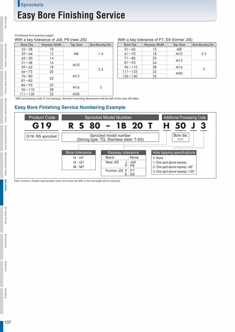
137
Sprockets
Easy Bore Finishing Service
Note: Contact a Tsubaki representative when set screws will differ or the hub length will be machined.
Sprocket Model Number Additional Processing Code
Easy Bore Finishing Service Numbering Example
G19 R S 80 - 1B 20 T H 50 J 3Sprocket model number
(Strong type: TQ, Stainless steel: T-SS)Bore dia.mm
Bore tolerance Hole tapping specificationsKeyway tolerance
(Continued from previous page)
・With processing code IV (no keyway), the bore mounting dimensions will be half of the new JIS table.
With a key tolerance of Js9, P9 (new JIS)
33~3839~4445~5051~5859~6566~7576~8081~8586~95
96~110111~130
101214161820
22
252832
M8
M10
M12
M16
M20
1.6
2.5
3
With a key tolerance of F7, E9 (former JIS)
51~6061~7071~8081~95
96~110111~125126~140
15182024283235
M8M10
M12
M16
M20
2.5
3
Bore Dia. Keyway Width Tap Size Bore Mounting Dim. Bore Dia. Keyway Width Tap Size Bore Mounting Dim.
0: None1: One spot above keyway2: One spot above keyway +90°3: One spot above keyway +120°
Product Code
G19: RS sprocket
H : H7G : G7M : M7
Blank : NoneNew JIS J : Js9 P : P9Former JIS F : F7 E : E9
Befo
re Use
Standard R
oller Chains
Lube-Free Roller C
hainsH
eavy Duty R
oller Chains
Corrosion Resistant Roller ChainsS
pecialty Roller C
hainsS
pro
cketsP
in G
ear Drives
Accesso
riesS
election
Han
dlin
g
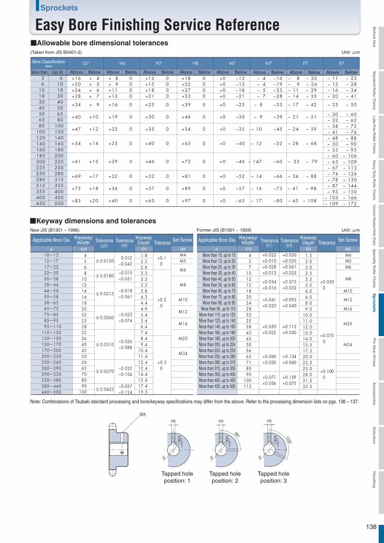
138
Sprockets
Easy Bore Finishing Service Reference
■Keyway dimensions and tolerances
■Allowable bore dimensional tolerances
Applicable Bore Dia. KeywayWidth Tolerance
(Js9)
KeywayDepth Tolerance Set Screw
(F7)d KW KH MX d KW KH MX
± 0.01501.82.32.83.33.33.33.84.34.44.95.45.46.47.48.49.4
10.411.412.412.414.415.417.419.5
+0.10
M4 +0.022+0.010
+0.0500
M4M5M6
M5
M6+0.028+0.013
± 0.0180
+0.20
M8
M10M8
+0.034+0.016
± 0.0215M10 +0.041
+0.020M12
M16
± 0.0260M12
+0.050+0.025
M20M16
+0.0750
± 0.0310M20
+0.30
M24
M 24+0.060+0.030
± 0.0370 +0.1000+0.071
+0.036
(E9)
+0.050+0.020+0.061+0.025
+0.075+0.032
+0.092+0.040
+0.112+0.050
+0.134+0.060
+0.159+0.072
± 0.0435
Tolerance(P9)
0.012
−0.015
−0.018
−0.022
−0.026
−0.032
−0.037
−0.042
−0.051
−0.061
−0.074
−0.088
−0.106
−0.124
G7 H6 H7 H8 M7 N7 P7 R7mmUp to Above Below Above Below Above Below Above Below Above Below Above Below Above Below BelowAbove
36
1018
6101830
30 4040 5050 6565 8080 100
100 120120 140140 160160 180180 200200 225225 250250 280280 315315 355355 400400 450450 500
Applicable Bore Dia. KeywayWidth Tolerance Keyway
Depth Tolerance Set ScrewTolerance
10~1212~1717~2222~3030~3838~4444~5050~5858~6565~7575~8585~9595~110
110~130130~150150~170170~200200~230230~260260~290290~330330~380380~440440~500
4568
10121416182022252832364045505663708090
100
1.52.03.03.53.55.06.06.08.09.0
10.011.012.013.014.015.517.520.022.525.028.031.535.5
457
101215182024283235384245505663718090
100112
New JIS (B1301 – 1996) Former JIS (B1301 – 1959)
+16+20+24+28
+ 4+ 5+ 6+ 7
+34
+40
+47
+54
+61
+69
+75
+83
+ 8+ 9+11+13
+16
+19
+22
+25
+29
+32
+36
+40
+12+15+18+21
+25
+30
+35
+40
+46
+52
+57
+63
−12−15−18−21
−25
−30
−35
−40
−46
−52
−57
−63
−16−19−23−28
−33
−39
−45
−52
−60
−66
−73
−80
+18+22+27+33
+39
+46
+54
+63
+72
+81
+89
+97
− 11− 13− 16− 20
− 30− 32− 38− 41− 48− 50− 53− 60− 63− 67− 74− 78− 87− 93
− 103− 109
− 60− 62− 73− 76− 88− 90− 93
− 106− 109− 113− 126− 130− 144− 150− 166− 172
− 25
− 23− 28− 34− 41
− 50
− 4− 4− 5− 7
− 8
− 9
− 10
− 12
− 147
− 14
− 16
− 17
− 8− 9− 11− 14
− 17
− 21
− 24
− 28
− 33
− 36
− 41
− 45
− 20− 24− 29− 35
− 42
− 51
− 59
− 68
− 79
− 88
− 98
− 108
+0+0+0+0
+0
+0
+0
+0
+0
+0
+0
+0
+ 9
+10
+12
+14
+15
+17
+18
+20
0000
0
0
0
0
0
0
0
0
0000
0
0
0
0
0
0
0
0
0000
0
0
0
0
0
0
0
0
(Taken from JIS B0401-2)
MX
120°
KW
KH
KW
KH
90°
KW
KH
Tapped holeposition: 1
Tapped holeposition: 2
Tapped holeposition: 3
Bore Classification
More than
Unit : μm
Unit : μm
Note: Combinations of Tsubaki standard processing and bore/keyway specifications may differ from the above. Refer to the processing dimension lists on pgs. 136 – 137.
More than 10, up to 13More than 13, up to 20More than 20, up to 30More than 30, up to 40More than 40, up to 50More than 50, up to 60More than 60, up to 70More than 70, up to 80More than 80, up to 95
More than 95, up to 110More than 110, up to 125More than 125, up to 140More than 140, up to 160More than 160, up to 180More than 180, up to 200More than 200, up to 224More than 224, up to 250More than 250, up to 280More than 280, up to 315More than 315, up to 355More than 355, up to 400More than 400, up to 450More than 450, up to 500
Befo
re Use
Standard R
oller Chains
Lube-Free Roller C
hainsH
eavy Duty R
oller Chains
Corrosion Resistant Roller ChainsS
pecialty Roller C
hainsS
pro
cketsP
in G
ear Drives
Accesso
riesS
election
Han
dlin
g
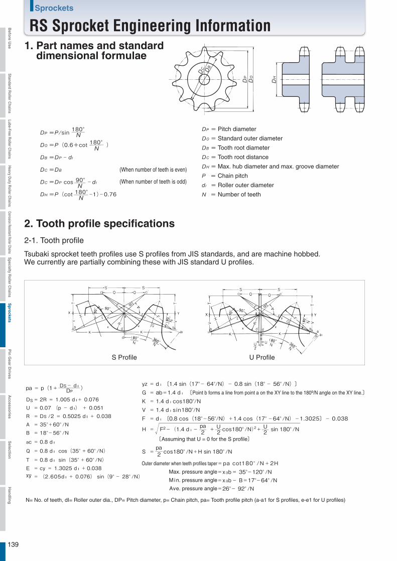
139
Sprockets
RS Sprocket Engineering Information
180°
)
-
90°-
180°-1)-0.76
=
=
=
=
=
=
=
=
2. Tooth profile specifications
2-1. Tooth profile
pa = p(1+ DS- d l )
DS = 2R = 1.005 d l+ 0.076U = 0.07 (p - d l) + 0.051R = DS /2 = 0.5025 d l + 0.038A = 35°+60°/NB = 18°-56°/N
ac = 0.8 d l
Q = 0.8 d l cos(35°+60°/N)
T = 0.8 d l sin(35°+60°/N)E = cy = 1.3025 d l +0.038xy = (2.605d l + 0.076) sin(9°- 28°/N)
yz = d l 〔1.4 sin(17°- 64°/N)- 0.8 sin(18°- 56°/N)〕G = ab=1.4 d l 〔Point b forms a line from point a on the XY line to the 180º/N angle on the XY line.〕K = 1.4 d l cos180°/NV = 1.4 d l s in180°/NF = d l 〔0.8 cos(18°-56°/N)+1.4 cos(17°-64°/N)-1.3025〕- 0.038
H = F2- (1.4 d l - pa + U cos180°/N)2+ U sin 180°/N
〔Assuming that U = 0 for the S profile〕
S = pa cos180°/N+H sin 180°/N
=pa cot180°/N+2H=xab= 35°-120°/N=xab- B=17°-64°/N=26°- 92°/N
DP
2 2 2
2
N= No. of teeth, dI= Roller outer dia., DP= Pitch diameter, p= Chain pitch, pa= Tooth profile pitch (a-a1 for S profiles, e-e1 for U profiles)
S Profile U Profile
1. Part names and standard dimensional formulae
(When number of teeth is even)
(When number of teeth is odd)
Pitch diameter
Standard outer diameter
Tooth root diameter
Tooth root distance
Max. hub diameter and max. groove diameter
Chain pitch
Roller outer diameter
Number of teeth
Tsubaki sprocket teeth profiles use S profiles from JIS standards, and are machine hobbed. We currently are partially combining these with JIS standard U profiles.
Outer diameter when teeth profiles taper
Max. pressure angle
M in. pressure angle
Ave. pressure angle
Befo
re Use
Standard R
oller Chains
Lube-Free Roller C
hainsH
eavy Duty R
oller Chains
Corrosion Resistant Roller ChainsS
pecialty Roller C
hainsS
pro
cketsP
in G
ear Drives
Accesso
riesS
election
Han
dlin
g
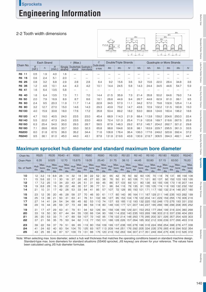
140
Sprockets
Engineering Information
Chain No.Each Strand (Max.)
Double strandsor more
Double/Triple Strands Quadruple or More Strands
(ref.) (min.)Singlestrand
Double/triplestrands
Quadruple ormore strands
RS 11 0.5 1.9 4.0 1.6 ― ― ― ― ― ― ― ― ― ― ― ―RS 15 0.6 2.4 5.1 2.0 ― ― ― ― ― ― ― ― ― ― ― ―RS 25 0.8 3.2 6.8 2.9 2.8 2.8 6.4 9.2 15.6 3.6 9.2 15.6 22.0 28.4 34.8 3.6RS 35 1.2 4.8 10.1 4.4 4.3 4.2 10.1 14.4 24.5 5.8 14.3 24.4 34.5 44.6 54.7 5.9RS 41 1.6 6.4 13.5 5.8 ― ― ― ― ― ― ― ― ― ― ― ―
RS 40 1.6 6.4 13.5 7.3 7.1 7.0 14.4 21.5 35.9 7.3 21.4 35.8 50.2 64.6 79.0 7.4RS 50 2.0 7.9 16.9 8.9 8.7 8.6 18.1 26.8 44.9 9.4 26.7 44.8 62.9 81.0 99.1 9.5RS 60 2.4 9.5 20.3 11.9 11.7 11.4 22.8 34.5 57.3 11.1 34.2 57.0 79.8 102.6 125.4 11.4RS 80 3.2 12.7 27.0 15.0 14.6 14.3 29.3 43.9 73.2 14.7 43.6 72.9 102.2 131.5 160.8 15.0RS100 4.0 15.9 33.8 18.0 17.6 17.2 35.8 53.4 89.2 18.2 53.0 88.8 124.6 160.4 196.2 18.6
RS120 4.7 19.0 40.5 24.0 23.5 23.0 45.4 68.9 114.3 21.9 68.4 113.8 159.2 204.6 250.0 22.4RS140 5.5 22.2 47.3 24.0 23.5 23.0 48.9 72.4 121.3 25.4 71.9 120.8 169.7 218.6 267.5 25.9RS160 6.3 25.4 54.0 30.0 29.3 28.7 58.5 87.8 146.3 29.2 87.2 145.7 204.2 262.7 321.2 29.8RS180 7.1 28.6 60.8 33.7 33.0 32.3 65.8 98.8 164.6 32.8 98.1 163.9 229.7 295.5 361.3 33.5RS200 8.0 31.8 67.5 36.0 35.2 34.4 71.6 106.8 178.4 36.4 106.0 177.6 249.2 320.8 392.4 37.2RS240 9.5 38.1 81.0 45.0 44.0 43.1 87.8 131.8 219.6 43.8 130.9 218.7 306.5 394.3 482.1 44.7
Chain No. RS25 RS35 RS40・41 RS50 RS60 RS80 RS100 RS120 RS140 RS160 RS180 RS200 RS240
Chain Pitch 6.35 9.525 12.70 15.875 19.05 25.40 31.75 38.10 44.45 50.80 57.15 63.50 76.20
No. of TeethHubdia.
Max.boredia.
Hubdia.
Max.boredia.
Hubdia.
Max.boredia.
Hubdia.
Max.boredia.
Hubdia.
Max.boredia.
Hubdia.
Max.boredia.
Hubdia.
Max.boredia.
Hubdia.
Max.boredia.
Hubdia.
Max.boredia.
Hubdia.
Max.boredia.
Hubdia.
Max.boredia.
Hubdia.
Max.boredia.
Hubdia.
Max.boredia.
10 12 3.2 19 8.8 26 14 32 18 39 22 52 32 65 42 78 50 92 60 105 70 118 78 131 88 158 10811 15 5.6 22 11 30 18 37 22 45 27 60 38 76 50 91 60 106 71 121 80 137 92 152 103 183 12612 17 7.2 25 13 34 20 43 26 51 31 69 45 86 57 103 69 121 80 138 93 155 106 173 118 207 14413 19 8.8 28 15 38 22 48 30 57 36 77 51 96 64 116 79 135 91 155 105 174 119 193 132 232 16214 21 10 31 17 42 26 53 33 64 41 85 57 107 72 128 85 150 101 171 117 192 132 214 148 257 180
15 23 12 35 20 46 28 58 37 70 46 93 61 117 80 140 95 164 111 187 129 211 146 235 163 282 19916 25 13 38 21 50 31 63 41 76 51 102 68 127 85 153 104 178 122 204 141 229 159 255 179 306 21617 27 14 41 24 54 34 68 45 82 53 110 74 137 93 165 112 193 132 220 152 248 173 275 193 331 23218 29 16 44 26 59 37 73 49 88 59 118 80 148 100 177 121 207 144 237 165 266 186 296 208 355 252
19 31 17 47 29 63 41 79 51 94 62 126 84 158 108 189 129 221 153 253 177 284 199 316 224 380 26820 33 19 50 30 67 44 84 55 100 66 134 90 168 114 202 140 235 163 269 188 303 213 337 238 404 28321 35 20 53 33 71 47 89 59 107 72 142 95 178 122 214 148 250 175 285 200 321 226 357 254 429 30322 37 21 56 35 75 50 94 62 113 77 150 101 188 128 226 157 264 185 302 212 339 239 377 266 453 318
23 39 22 59 37 79 51 99 65 119 80 159 109 199 137 238 165 278 196 318 224 358 254 398 278 477 33824 41 24 62 40 83 54 104 70 125 83 167 113 209 144 251 176 292 205 334 235 376 265 418 294 502 35425 43 25 65 42 87 57 109 73 131 88 175 120 219 152 263 184 307 217 351 249 394 275 438 310 526 372
2-2 Tooth width dimensions
Maximum sprocket hub diameter and standard maximum bore diameter
Note: When selecting max. bore diameter, select a hub wall thickness that matches the operating conditions based on standard machine design. Standard-type max. bore diameters for standard situations (SS400 sprocket, JIS keyway) are shown for your reference. The values have been calculated using JIS hub diameter formulae.
Befo
re Use
Standard R
oller Chains
Lube-Free Roller C
hainsH
eavy Duty R
oller Chains
Corrosion Resistant Roller ChainsS
pecialty Roller C
hainsS
pro
cketsP
in G
ear Drives
Accesso
riesS
election
Han
dlin
g

Pg. 143Pg. 142
Pg. 145Pg. 150
141
Sprockets for Chain-type Pin GearsAttachment Chains for Chain-type Pin GearsPin Gear Drive UnitsSelection Guide for Pin Gear Drive Units
Pin GearProducts Guide
Index
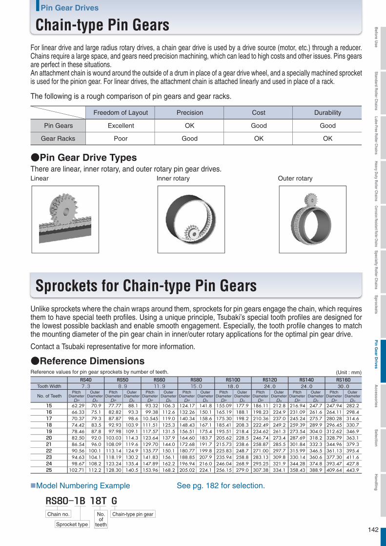
142
Pin Gear Drives
Chain-type Pin GearsFor linear drive and large radius rotary drives, a chain gear drive is used by a drive source (motor, etc.) through a reducer. Chains require a large space, and gears need precision machining, which can lead to high costs and other issues. Pins gears are perfect in these situations.An attachment chain is wound around the outside of a drum in place of a gear drive wheel, and a specially machined sprocket is used for the pinion gear. For linear drives, the attachment chain is attached linearly and used in place of a rack.
Unlike sprockets where the chain wraps around them, sprockets for pin gears engage the chain, which requires them to have special teeth profiles. Using a unique principle, Tsubaki’s special tooth profiles are designed for the lowest possible backlash and enable smooth engagement. Especially, the tooth profile changes to match the mounting diameter of the pin gear chain in inner/outer rotary applications for the optimal pin gear drive.
Contact a Tsubaki representative for more information.
The following is a rough comparison of pin gears and gear racks.
●Pin Gear Drive TypesThere are linear, inner rotary, and outer rotary pin gear drives.Linear Inner rotary Outer rotary
Freedom of Layout Precision Cost Durability
Pin Gears Excellent OK Good Good
Gear Racks Poor Good OK OK
●Reference Dimensions
■Model Numbering Example
Chain no. No.
ofteethSprocket type
Chain-type pin gear
Tooth Width
No. of TeethPitch
DiameterOuter
DiameterPitch
DiameterOuter
DiameterPitch
DiameterOuter
DiameterPitch
DiameterOuter
DiameterPitch
DiameterOuter
DiameterPitch
DiameterOuter
DiameterPitch
DiameterOuter
DiameterPitch
DiameterOuter
Diameter
62.2966.3370.3774.4278.4682.5086.5490.5694.6398.67
102.71
70.975.179.383.587.892.096.0
100.1104.1108.2112.2
77.7782.8287.8792.9397.98
103.03108.09113.14118.19123.24128.30
88.193.398.6
103.9109.1114.3119.6124.9130.2135.4140.5
93.3299.38
10.545111.51117.57123.64129.70135.77141.83147.89153.96
106.3112.6119.0125.3131.5137.9144.0150.1156.1162.2168.2
124.17132.26140.34148.43156.51164.60172.68180.77188.85196.94205.02
141.8150.1158.6167.1175.4183.7191.7199.8207.9216.0224.1
155.09165.19175.30185.41195.51205.62215.73225.83235.94246.04256.15
177.9188.1198.2208.3218.4228.5238.6248.7258.8268.9279.0
186.11198.23210.36222.49234.62246.74258.87271.00283.13295.25307.38
212.8224.9237.0249.2261.3273.4285.5297.7309.8321.9334.1
216.94231.09245.24259.39273.54287.69301.84315.99330.14344.28358.43
247.7261.6275.7289.9304.0318.2332.3346.5360.6374.8388.9
247.94264.11280.28296.45312.62328.79344.96361.13377.30393.47409.64
282.2298.4314.6330.7346.9363.1379.3395.4411.6427.8443.9
Sprockets for Chain-type Pin Gears
Reference values for pin gear sprockets by number of teeth. (Unit : mm)
See pg. 182 for selection.
Befo
re Use
Standard R
oller Chains
Lube-Free Roller C
hainsH
eavy Duty R
oller Chains
Corrosion Resistant Roller ChainsS
pecialty Roller C
hainsS
pro
cketsP
in G
ear Drives
Accesso
riesS
election
Han
dlin
g
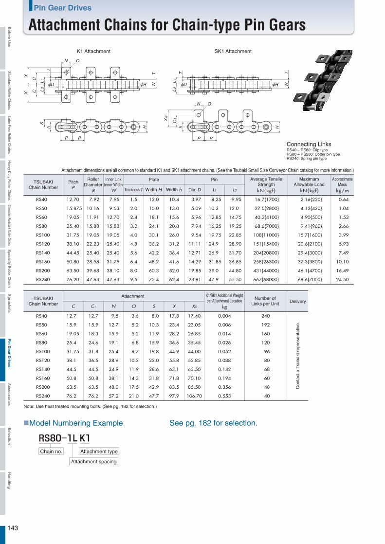
143
Pin Gear Drives
Attachment Chains for Chain-type Pin Gears
Attachment K1/SK1 Additional Weightper Attachment Location
kg
Number ofLinks per Unit Delivery
C C1 N O S X XS
RS40 12.7 12.7 9.5 3.6 8.0 17.8 17.40 0.004 240
RS50 15.9 15.9 12.7 5.2 10.3 23.4 23.05 0.006 192
RS60 19.05 18.3 15.9 5.2 11.9 28.2 26.85 0.014 160
RS80 25.4 24.6 19.1 6.8 15.9 36.6 35.45 0.026 120
RS100 31.75 31.8 25.4 8.7 19.8 44.9 44.00 0.052 96
RS120 38.1 36.5 28.6 10.3 23.0 55.8 52.85 0.088 80
RS140 44.5 44.5 34.9 11.9 28.6 63.1 63.50 0.142 68
RS160 50.8 50.8 38.1 14.3 31.8 71.8 70.10 0.194 60
RS200 63.5 63.5 48.0 17.5 42.9 83.5 85.50 0.356 48
RS240 76.2 76.2 57.2 21.0 47.7 97.9 106.70 0.553 40
TSUBAKIChain Number
TSUBAKIChain Number
PitchP
RollerDiameter
R
Inner LinkInner Width
W
Plate Pin Average TensileStrengthkN{kg f }
MaximumAllowable Load
kN{kg f }
ApproximateMass
kg/mThickness T Width H Width h Dia. D L1 L2
RS40 12.70 7.92 7.95 1.5 12.0 10.4 3.97 8.25 9.95 16.7{1700} 2.16{220} 0.64
RS50 15.875 10.16 9.53 2.0 15.0 13.0 5.09 10.3 12.0 27.5{2800} 4.12{420} 1.04
RS60 19.05 11.91 12.70 2.4 18.1 15.6 5.96 12.85 14.75 40.2{4100} 4.90{500} 1.53
RS80 25.40 15.88 15.88 3.2 24.1 20.8 7.94 16.25 19.25 68.6{7000} 9.41{960} 2.66
RS100 31.75 19.05 19.05 4.0 30.1 26.0 9.54 19.75 22.85 108{11000} 15.7{1600} 3.99
RS120 38.10 22.23 25.40 4.8 36.2 31.2 11.11 24.9 28.90 151{15400} 20.6{2100} 5.93
RS140 44.45 25.40 25.40 5.6 42.2 36.4 12.71 26.9 31.70 204{20800} 29.4{3000} 7.49
RS160 50.80 28.58 31.75 6.4 48.2 41.6 14.29 31.85 36.85 258{26300} 37.3{3800} 10.10
RS200 63.50 39.68 38.10 8.0 60.3 52.0 19.85 39.0 44.80 431{44000} 46.1{4700} 16.49
RS240 76.20 47.63 47.63 9.5 72.4 62.4 23.81 47.9 55.50 667{68000} 68.6{7000} 24.50
Attachment dimensions are all common to standard K1 and SK1 attachment chains. (See the Tsubaki Small Size Conveyor Chain catalog for more information.)
T
L1
L2
N O
Xs
hC
1
TW
P P
H
RD
T
N O
C
XX
P P
h
C
L1
TW
L2
S
H
RD
■Model Numbering Example
Attachment type
Attachment spacing
See pg. 182 for selection.
L KChain no.
K1 Attachment SK1 Attachment
Connecting LinksRS40 – RS60: Clip typeRS80 – RS200: Cotter pin typeRS240: Spring pin type
Con
tact
a T
suba
ki r
epre
sent
ativ
e.
Note: Use heat treated mounting bolts. (See pg. 182 for selection.)
Befo
re Use
Standard R
oller Chains
Lube-Free Roller C
hainsH
eavy Duty R
oller Chains
Corrosion Resistant Roller ChainsS
pecialty Roller C
hainsS
pro
cketsP
in G
ear Drives
Accesso
riesS
election
Han
dlin
g
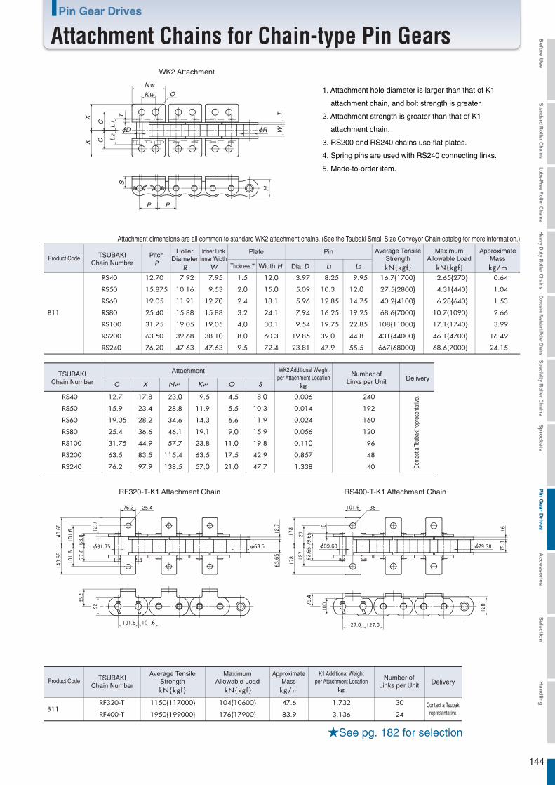
144
Pin Gear Drives
Attachment Chains for Chain-type Pin Gears
Product Code
RS40 12.70 7.92 7.95 1.5 12.0 3.97 8.25 9.95 16.7{1700} 2.65{270} 0.64
RS50 15.875 10.16 9.53 2.0 15.0 5.09 10.3 12.0 27.5{2800} 4.31{440} 1.04
RS60 19.05 11.91 12.70 2.4 18.1 5.96 12.85 14.75 40.2{4100} 6.28{640} 1.53
RS80B11
B11
25.40 15.88 15.88 3.2 24.1 7.94 16.25 19.25 68.6{7000} 10.7{1090} 2.66
RS100 31.75 19.05 19.05 4.0 30.1 9.54 19.75 22.85 108{11000} 17.1{1740} 3.99
RS200 63.50 39.68 38.10 8.0 60.3 19.85 39.0 44.8 431{44000} 46.1{4700} 16.49
RS240 76.20 47.63 47.63 9.5 72.4 23.81 47.9 55.5 667{68000} 68.6{7000} 24.15
RF320-T 1150{117000} 104{10600} 47.6 1.732 30 Contact a Tsubakirepresentative.RF400-T 1950{199000} 176{17900} 83.9 3.136 24
kgC X Nw Kw O S
RS40 12.7 17.8 23.0 9.5 4.5 8.0 0.006 240
RS50 15.9 23.4 28.8 11.9 5.5 10.3 0.014 192
RS60 19.05 28.2 34.6 14.3 6.6 11.9 0.024 160
RS80 25.4 36.6 46.1 19.1 9.0 15.9 0.056 120
RS100 31.75 44.9 57.7 23.8 11.0 19.8 0.110 96
RS200 63.5 83.5 115.4 63.5 17.5 42.9 0.857 48
RS240 76.2 97.9 138.5 57.0 21.0 47.7 1.338 40
Attachment dimensions are all common to standard WK2 attachment chains. (See the Tsubaki Small Size Conveyor Chain catalog for more information.)
CC
TXX
L1
L2
H
TW
P P
SRD
O
Nw
Kw
39.68
★See pg. 182 for selection
WK2 Attachment
1. Attachment hole diameter is larger than that of K1
attachment chain, and bolt strength is greater.
2. Attachment strength is greater than that of K1
attachment chain.
3. RS200 and RS240 chains use flat plates.
4. Spring pins are used with RS240 connecting links.
5. Made-to-order item.
Attachment Number ofLinks per Unit Delivery
Number ofLinks per Unit Delivery
TSUBAKIChain Number
Product Code TSUBAKIChain Number
TSUBAKIChain Number
PitchP
RollerDiameter
R
Inner LinkInner Width
W
Plate Pin Average TensileStrength
WK2 Additional Weightper Attachment Location
kg
K1 Additional Weightper Attachment Location
kN{kg f }
MaximumAllowable Load
kN{kg f }
ApproximateMasskg/m
Average TensileStrengthkN{kg f }
MaximumAllowable Load
kN{kg f }
ApproximateMass
kg/m
Thickness T Width H Dia. D L1 L2
Cont
act a
Tsub
aki r
epre
sent
ative
.
RF320-T-K1 Attachment Chain RS400-T-K1 Attachment Chain
Befo
re Use
Standard R
oller Chains
Lube-Free Roller C
hainsH
eavy Duty R
oller Chains
Corrosion Resistant Roller ChainsS
pecialty Roller C
hainsS
pro
cketsP
in G
ear Drives
Accesso
riesS
election
Han
dlin
g
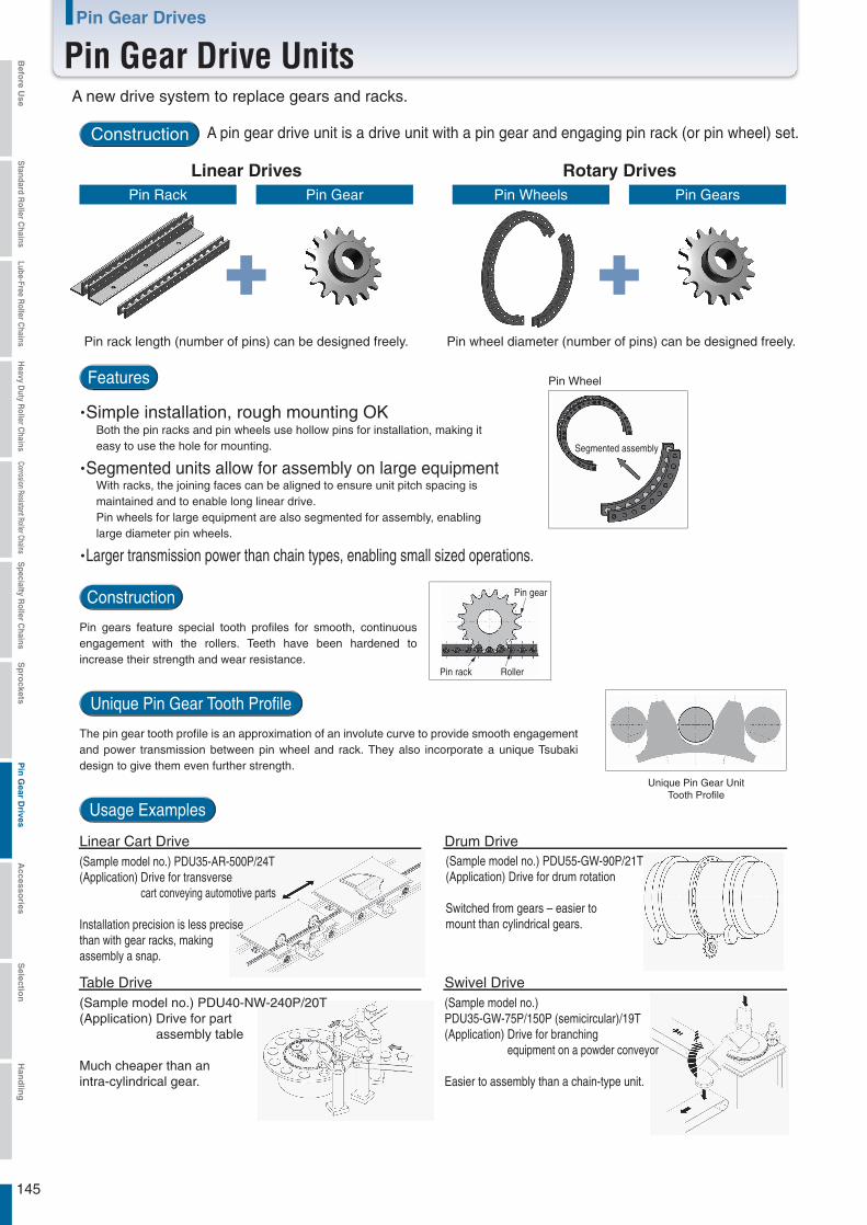
145
Pin Gear Drives
Pin Gear Drive Units
A pin gear drive unit is a drive unit with a pin gear and engaging pin rack (or pin wheel) set.
Features
・Simple installation, rough mounting OK ・Segmented units allow for assembly on large equipment
・Larger transmission power than chain types, enabling small sized operations.
Construction
Pin gears feature special tooth profiles for smooth, continuous engagement with the rollers. Teeth have been hardened to increase their strength and wear resistance.
Usage Examples
Unique Pin Gear Tooth Profile
The pin gear tooth profile is an approximation of an involute curve to provide smooth engagement and power transmission between pin wheel and rack. They also incorporate a unique Tsubaki design to give them even further strength.
Pin Rack Pin Gear Pin Wheels Pin Gears
Pin wheel diameter (number of pins) can be designed freely.
Pin gear
Pin rack Roller
(Sample model no.) PDU35-GW-75P/150P (semicircular)/19T(Application) Drive for branching equipment on a powder conveyor
Easier to assembly than a chain-type unit.
A new drive system to replace gears and racks.
Construction
Linear Drives Rotary Drives
Pin rack length (number of pins) can be designed freely.
Both the pin racks and pin wheels use hollow pins for installation, making it easy to use the hole for mounting.
With racks, the joining faces can be aligned to ensure unit pitch spacing is maintained and to enable long linear drive.Pin wheels for large equipment are also segmented for assembly, enabling large diameter pin wheels.
Pin Wheel
Segmented assembly
Unique Pin Gear UnitTooth Profile
Linear Cart Drive
Table Drive
Drum Drive
Swivel Drive
(Sample model no.) PDU35-AR-500P/24T(Application) Drive for transverse cart conveying automotive parts
Installation precision is less precise than with gear racks, making assembly a snap.
(Sample model no.) PDU40-NW-240P/20T(Application) Drive for part assembly table
Much cheaper than an intra-cylindrical gear.
(Sample model no.) PDU55-GW-90P/21T(Application) Drive for drum rotation
Switched from gears – easier to mount than cylindrical gears.
Befo
re Use
Standard R
oller Chains
Lube-Free Roller C
hainsH
eavy Duty R
oller Chains
Corrosion Resistant Roller ChainsS
pecialty Roller C
hainsS
pro
cketsP
in G
ear Drives
Accesso
riesS
election
Han
dlin
g
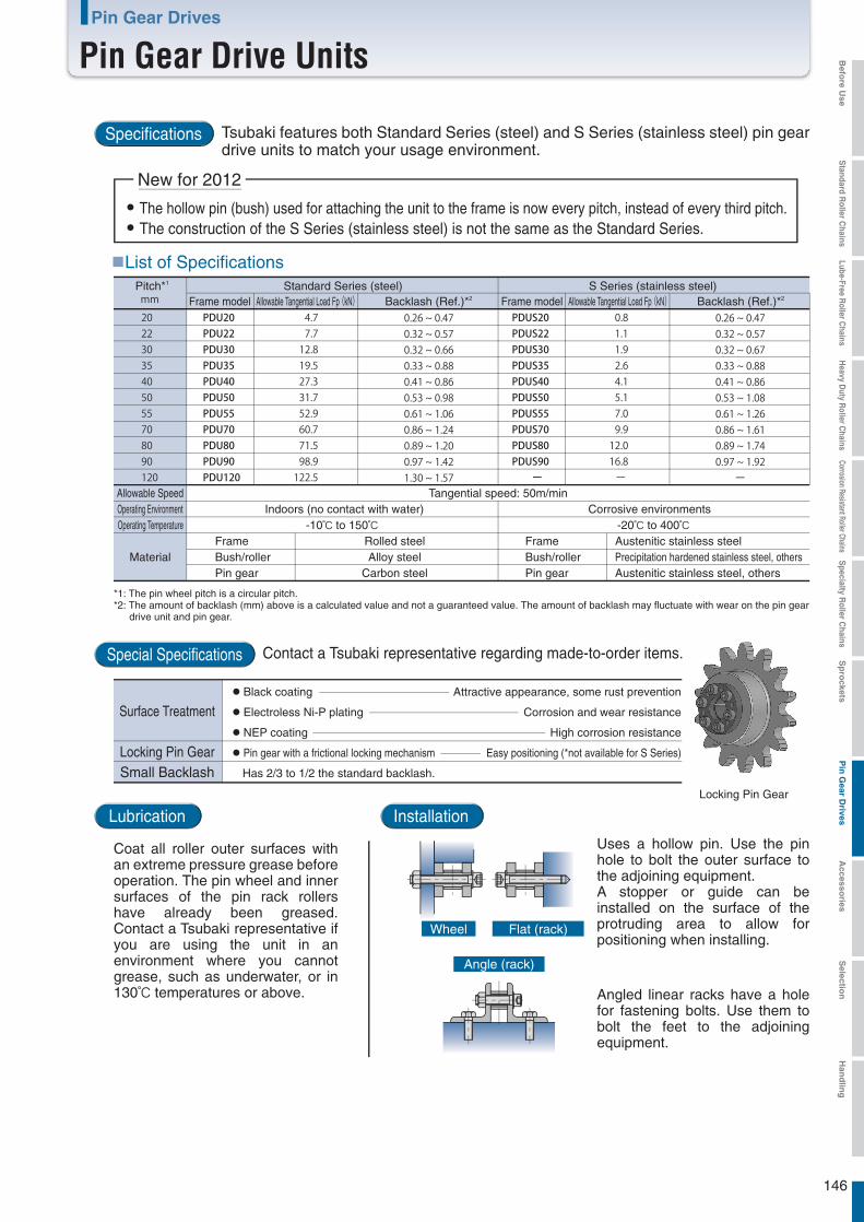
146
Pin Gear Drives
Pin Gear Drive Units
Specifications Tsubaki features both Standard Series (steel) and S Series (stainless steel) pin gear drive units to match your usage environment.
Special Specifications Contact a Tsubaki representative regarding made-to-order items.
● The hollow pin (bush) used for attaching the unit to the frame is now every pitch, instead of every third pitch.● The construction of the S Series (stainless steel) is not the same as the Standard Series.
New for 2012
■List of Specifications
Allowable SpeedOperating Environment Indoors (no contact with water) Corrosive environmentsOperating Temperature
Frame Rolled steelAlloy steel
Carbon steel
FrameBush/roller Bush/rollerPin gear Pin gear
Austenitic stainless steelPrecipitation hardened stainless steel, othersAustenitic stainless steel, others
-10℃ to 150℃ -20℃ to 400℃
Material
Tangential speed: 50m/min
Pitch*1
Attractive appearance, some rust prevention
Corrosion and wear resistance
High corrosion resistance
Easy positioning (*not available for S Series)
Has 2/3 to 1/2 the standard backlash.
● Black coating
● Electroless Ni-P plating
● NEP coating
● Pin gear with a frictional locking mechanism
Lubrication
Coat all roller outer surfaces with an extreme pressure grease before operation. The pin wheel and inner surfaces of the pin rack rollers have already been greased. Contact a Tsubaki representative if you are using the unit in an environment where you cannot grease, such as underwater, or in 130℃ temperatures or above.
Installation
Uses a hollow pin. Use the pin hole to bolt the outer surface to the adjoining equipment.A stopper or guide can be installed on the surface of the protruding area to allow for positioning when installing.
Flat (rack)Wheel
Angled linear racks have a hole for fastening bolts. Use them to bolt the feet to the adjoining equipment.
Angle (rack)
Backlash (Ref.)*2
Standard Series (steel) S Series (stainless steel)Frame model Allowable Tangential Load Fp (kN) Backlash (Ref.)*2Frame model Allowable Tangential Load Fp (kN)
*1: The pin wheel pitch is a circular pitch.*2: The amount of backlash (mm) above is a calculated value and not a guaranteed value. The amount of backlash may fluctuate with wear on the pin gear drive unit and pin gear.
Surface Treatment
Locking Pin GearSmall Backlash
Locking Pin Gear
Befo
re Use
Standard R
oller Chains
Lube-Free Roller C
hainsH
eavy Duty R
oller Chains
Corrosion Resistant Roller ChainsS
pecialty Roller C
hainsS
pro
cketsP
in G
ear Drives
Accesso
riesS
election
Han
dlin
g
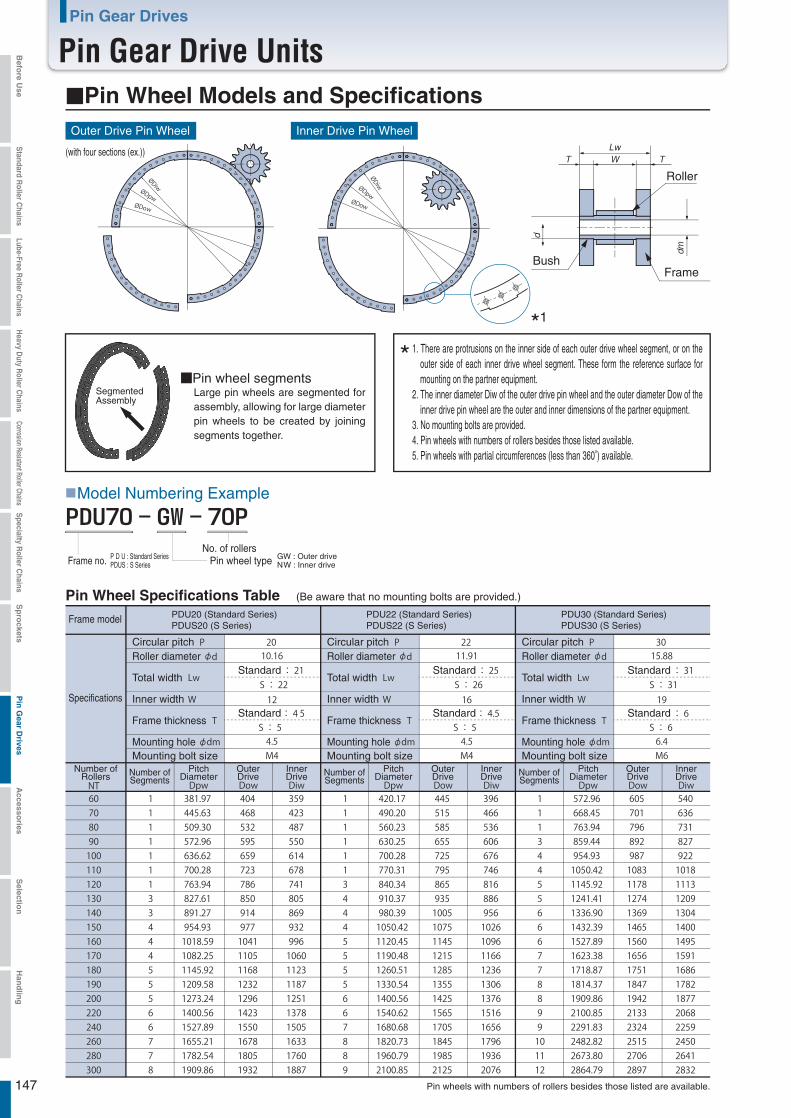
147
Pin Gear Drives
Pin Gear Drive Units
Pin wheels with numbers of rollers besides those listed are available.
■Pin wheel segments
LwWT T
dm
d
■Model Numbering Example
1. There are protrusions on the inner side of each outer drive wheel segment, or on the outer side of each inner drive wheel segment. These form the reference surface for mounting on the partner equipment.
2. The inner diameter Diw of the outer drive pin wheel and the outer diameter Dow of the inner drive pin wheel are the outer and inner dimensions of the partner equipment.
3. No mounting bolts are provided.4. Pin wheels with numbers of rollers besides those listed available.5. Pin wheels with partial circumferences (less than 360°) available.
PDU70 - GW - 70P
Pin wheel typeNo. of rollers
■Pin Wheel Models and SpecificationsOuter Drive Pin Wheel Inner Drive Pin Wheel
(with four sections (ex.))
Roller
BushFrame
*1
SegmentedAssembly
Large pin wheels are segmented for assembly, allowing for large diameter pin wheels to be created by joining segments together.
*
GW : Outer driveNW : Inner driveFrame no. P D U : Standard Series
PDUS : S Series
Pin Wheel Specifications Table (Be aware that no mounting bolts are provided.)
Frame model PDU20 (Standard Series)PDUS20 (S Series)
PDU22 (Standard Series)PDUS22 (S Series)
PDU30 (Standard Series)PDUS30 (S Series)
Standard
Standard
Standard
StandardSpecifications
Circular pitchRoller diameter
Inner width
Frame thickness
Total width
Mounting holeMounting bolt size
Circular pitchRoller diameter
Inner width
Frame thickness
Total width
Mounting holeMounting bolt size
Circular pitchRoller diameter
Inner width
Frame thickness
Total width
Mounting holeMounting bolt size
Standard
Standard
Number ofRollers Number of
SegmentsPitch
DiameterOuterDrive
InnerDrive Number of
SegmentsPitch
DiameterOuterDrive
InnerDrive Number of
SegmentsPitch
DiameterOuterDrive
InnerDrive
Befo
re Use
Standard R
oller Chains
Lube-Free Roller C
hainsH
eavy Duty R
oller Chains
Corrosion Resistant Roller ChainsS
pecialty Roller C
hainsS
pro
cketsP
in G
ear Drives
Accesso
riesS
election
Han
dlin
g
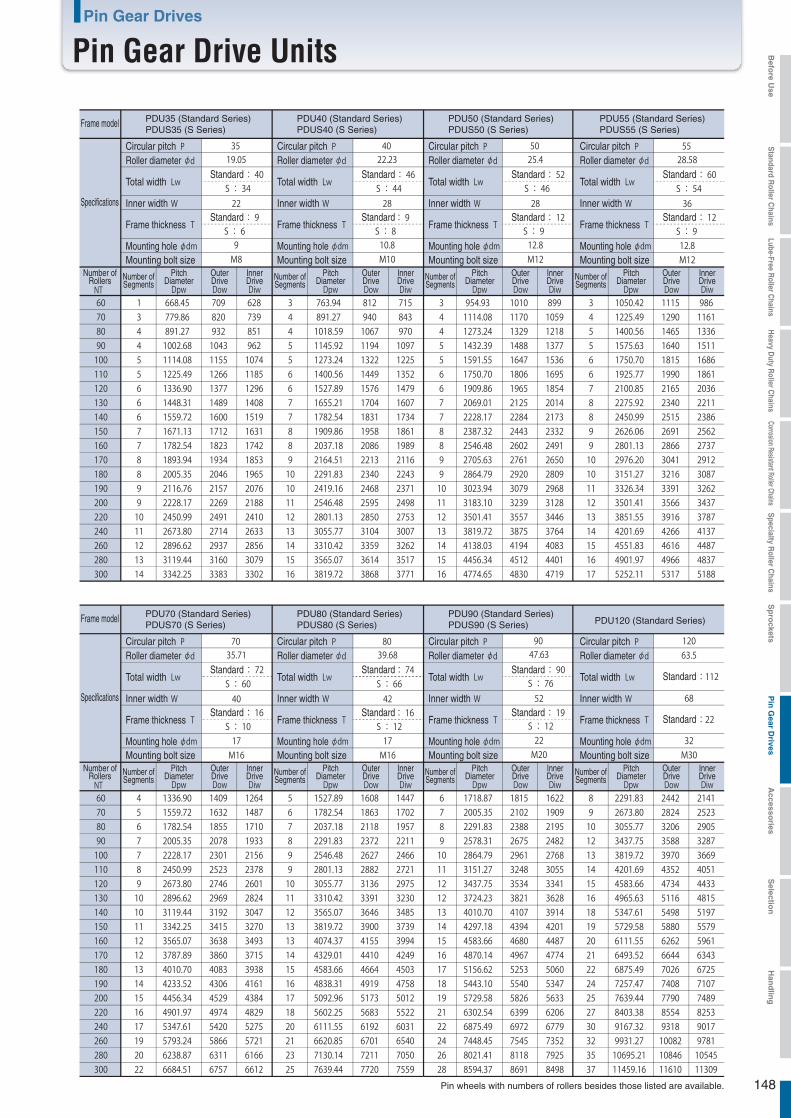
148
Pin Gear Drives
Pin Gear Drive Units
Pin wheels with numbers of rollers besides those listed are available.
Frame model PDU35 (Standard Series)PDUS35 (S Series)
PDU40 (Standard Series)PDUS40 (S Series)
PDU50 (Standard Series)PDUS50 (S Series)
PDU55 (Standard Series)PDUS55 (S Series)
Standard
Standard
Standard
StandardSpecifications
Circular pitchRoller diameter
Inner width
Frame thickness
Total width
Mounting holeMounting bolt size
Number ofRollers Number of
SegmentsPitch
DiameterOuterDrive
InnerDrive
Circular pitchRoller diameter
Inner width
Frame thickness
Total width
Mounting holeMounting bolt size
Number ofSegments
PitchDiameter
OuterDrive
InnerDrive
Circular pitchRoller diameter
Inner width
Frame thickness
Total width
Mounting holeMounting bolt size
Number ofSegments
PitchDiameter
OuterDrive
InnerDrive
Circular pitchRoller diameter
Inner width
Frame thickness
Total width
Mounting holeMounting bolt size
Number ofSegments
PitchDiameter
OuterDrive
InnerDrive
Frame model PDU70 (Standard Series)PDUS70 (S Series)
PDU80 (Standard Series)PDUS80 (S Series)
PDU90 (Standard Series)PDUS90 (S Series) PDU120 (Standard Series)
Specifications
Circular pitchRoller diameter
Inner width
Frame thickness
Total width
Mounting holeMounting bolt size
Number ofRollers Number of
SegmentsPitch
DiameterOuterDrive
InnerDrive
Circular pitchRoller diameter
Inner width
Frame thickness
Total width
Mounting holeMounting bolt size
Number ofSegments
PitchDiameter
OuterDrive
InnerDrive
Circular pitchRoller diameter
Inner width
Frame thickness
Total width
Mounting holeMounting bolt size
Number ofSegments
PitchDiameter
OuterDrive
InnerDrive
Circular pitchRoller diameter
Inner width
Frame thickness
Total width
Mounting holeMounting bolt size
Number ofSegments
PitchDiameter
OuterDrive
InnerDrive
Standard
Standard
Standard
Standard
Standard
Standard
Standard
Standard
Standard
Standard
Standard
Standard
Befo
re Use
Standard R
oller Chains
Lube-Free Roller C
hainsH
eavy Duty R
oller Chains
Corrosion Resistant Roller ChainsS
pecialty Roller C
hainsS
pro
cketsP
in G
ear Drives
Accesso
riesS
election
Han
dlin
g
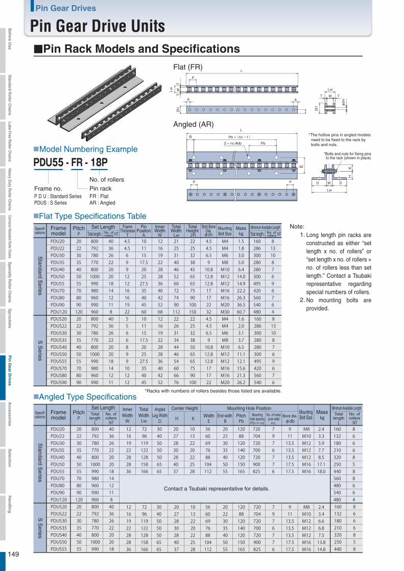
149
Pin Gear Drives
Pin Gear Drive Units■Pin Rack Models and Specifications
■Model Numbering Example
■Flat Type Specifications Table
■Angled Type Specifications
Long length pin racks are constructed as either “set length x no. of rollers” or “set length x no. of rollers + no. of rollers less than set length.” Contact a Tsubaki representative regarding special numbers of rollers.No mounting bolts are provided.
( -1)
Contact a Tsubaki representative for details.
*Bolts and nuts for fixing pins to the rack (shown in place).
Flat (FR)
Angled (AR)*The hollow pins in angled models need to be fixed to the rack by bolts and nuts.
FR : FlatAR : Angled
Frame no.P D U : Standard SeriesPDUS : S Series
No. of rollers
Pin rack
Framemodel
MountingBolt Size
Pitch Set LengthNo. ofrollers
FrameThickness
PinPosition
InnerWidth
TotalWidth
TotalHeight
Bolt BoreDia.
Total length No. ofrollersTotal length
Specifications
Framemodel
PitchSet Length
No. ofrollers
Mountinghole spacing
No. of holes(one side)
Totallength
No. ofrollers
Totallength
Specifications
Mass Minimum Available Length
MountingBolt Size
MassMinimum Available Length
S S
eriesS
tandard Series
S S
eriesS
tandard Series
Note: 1.
2.
*Racks with numbers of rollers besides those listed are available.
InnerWidth
TotalWidth
AngledLeg Width
Center Height Mounting Hole Position
Bore dia.Width End width Pitch
Befo
re Use
Standard R
oller Chains
Lube-Free Roller C
hainsH
eavy Duty R
oller Chains
Corrosion Resistant Roller ChainsS
pecialty Roller C
hainsS
pro
cketsP
in G
ear Drives
Accesso
riesS
election
Han
dlin
g
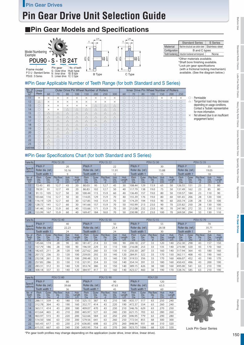
150
Pin Gear Drives
Pin Gear Drive Unit Selection Guide■Pin Gear Models and Specifications
■Pin Gear Applicable Number of Teeth Range (for both Standard and S Series)
■Pin Gear Specifications Chart (for both Standard and S Series)
Lock Pin Gear Series
P D U : Standard SeriesPDUS : S Series
*Pin gear tooth profiles may change depending on the application (outer drive, inner drive, linear drive).
Model NumberingExample
Frame modelPin gearG : Outer driveN : Inner driveS : Linear drive
No. of teeth
1B: B type1C: C type
Hub type
None
B Type C Type
Standard Series S SeriesStainless steelMaterial
ConfigurationMachine structural use carbon steel
B and C typesTooth hardening Induction hardened and tempered
*Other materials available.*Shaft bore finishing available.*Lock pin gear specifications (with a frictional locking mechanism) available. (See the diagram below.)
Inner Drive Pin Wheel Number of RollersNo. ofTeeth Linear
RackOuter Drive Pin Wheel Number of Rollers
and more
PermissibleTangential load may decrease depending on usage conditions. Contact a Tsubaki representative for more information.Not allowed (due to an insufficient engagement factor)
PitchRoller dia. (ref.)Tooth width
PitchRoller dia. (ref.)Tooth width
Frame No.
Specifications
PitchRoller dia. (ref.)Tooth width
PitchRoller dia. (ref.)Tooth width
No. ofTeeth
PitchDia.
OuterDia.
Pilot BoreDia.
HubDia.
HubLength
PitchDia.
OuterDia.
Pilot BoreDia.
HubDia.
HubLength
PitchDia.
OuterDia.
Pilot BoreDia.
HubDia.
HubLength
PitchDia.
OuterDia.
Pilot BoreDia.
HubDia.
HubLength
PitchRoller dia. (ref.)Tooth width
PitchRoller dia. (ref.)Tooth width
Frame No.
Specifications
PitchRoller dia. (ref.)Tooth width
No. ofTeeth
PitchDia.
OuterDia.
Pilot BoreDia.
HubDia.
HubLength
PitchDia.
OuterDia.
Pilot BoreDia.
HubDia.
HubLength
PitchDia.
OuterDia.
Pilot BoreDia.
HubDia.
HubLength
Befo
re Use
Standard R
oller Chains
Lube-Free Roller C
hainsH
eavy Duty R
oller Chains
Corrosion Resistant Roller ChainsS
pecialty Roller C
hainsS
pro
cketsP
in G
ear Drives
Accesso
riesS
election
Han
dlin
g
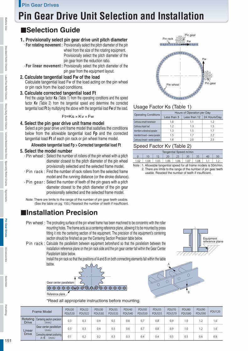
151
Pin Gear Drives
Pin Gear Drive Unit Selection and Installation■Selection Guide
■Installation Precision
1. Provisionally select pin gear drive unit pitch diameter
2. Calculate tangential load Fw of the load
For rotating movement :
For linear movement :
Provisionally select the pitch diameter of the pin wheel from the size of the rotating equipment.Provisionally select the pitch diameter of the pin gear from the reduction ratio.Provisionally select the pitch diameter of the pin gear from the equipment layout.
Calculate tangential load Fw of the load acting on the pin wheel or pin rack from the load conditions.
3. Calculate corrected tangential load FtFind the usage factor Ks (Table 1) from the operating conditions and the speed factor Kv (Table 2) from the tangential speed and determine the corrected tangential load Ft by multiplying the above with the tangential load Fw of the load.
4. Select the pin gear drive unit frame modelSelect a pin gear drive unit frame model that satisfies the conditions below from the allowable tangential load Fp and the corrected tangential load Ft of each pin rack or pin wheel frame model.
5. Select the model numberSelect the number of rollers of the pin wheel with a pitch diameter closest to the pitch diameter of the pin wheel provisionally selected and the selected frame model.Find the number of rack rollers from the selected frame model and the running distance (or the stroke distance).Select the number of teeth of the pin gears with a pitch diameter closest to the pitch diameter of the pin gear provisionally selected and the selected frame model.
Allowable tangential load Fp > Corrected tangential load Ft
Pin wheel :
Pin rack :
Pin gear :
The protruding surface of the pin wheel frame has been machined to be concentric with the roller mounting holes. The frame acts as a centering reference plane, allowing it to be mounted by press fitting it into the centering section of the equipment. The precision of the equipment’s centering section should be finished as per the Centering Section Precision table below.Calculate the parallelism between equipment beforehand so that the parallelism between the installation reference plane on the pin rack side and the pin gear center fall within the Gear Center Parallelism table below.Install the pin rack so that the positions of A and B on both connecting elements fall within the table below.
Pin wheel :
Pin rack :
Note: There are limits to the range of the number of pin gear teeth usable. (See the table on pg. 150.) Reselect the number of teeth if insufficient.
Continuous smooth transmission
Continuous impact load
Intermittent unidirectional operation
Intermittent forward – reverse operation
Continuous forward – reverse operation
Pin rackPin gear
Pin wheel Pin gear
Usage Factor Ks (Table 1)
Speed Factor Kv (Table 2)
Operating ConditionsHours of Operation per Day
Less than 3 Less than 12 24 Hours/Day
Tangential Speed m/min
Note : 1. Allowable tangential speed for all frame models is 50m/min. 2. There are limits to the range of the number of pin gear teeth usable. Reselect the number of teeth if insufficient.
Equipment reference plane
Reference plane
*Read all appropriate instructions before mounting.
Gear center parallelism
Frame Model
RotatingDrive
Centering section precision
Gear center parallelism
Connecting element positioningLinearDrive
Befo
re Use
Standard R
oller Chains
Lube-Free Roller C
hainsH
eavy Duty R
oller Chains
Corrosion Resistant Roller ChainsS
pecialty Roller C
hainsS
pro
cketsP
in G
ear Drives
Accesso
riesS
election
Han
dlin
g

152
Befo
re Use
Standard R
oller Chains
Lube-Free Roller C
hainsH
eavy Duty R
oller Chains
Corrosion Resistant Roller ChainsS
pecialty Roller C
hainsS
pro
cketsP
in G
ear Drives
Accesso
riesS
election
Han
dlin
g
This tool pulls the two ends of the chain together when installing the chain on a machine.
Chain Tensioners
Chain Connecting Tools
TCS Type
Chain Puller
The Tsubaki Chain Tensioner adjusts slackness in the chain to enable continuous and proper chain operation.
The end fitting bolts and end fitting bolt connecting links are designed to be stronger than those of RS Roller Chains.
Chain Vise
Punch Chain Breaker
Chain Cutting Tools End Fixtures
End Fitting Bolt End Fitting Bolt Connecting Link
Allows quick checks of pitch elongation limit.
Chain Elongation Scale
Chain Elongation Scale
These tools enable chains to be cut to the desired length.
Accessories (Peripheral Instruments)
1. Operational period can be freely set2. Reduces maintenance time3. Lightweight, compact4. Can be installed in any direction5. Waterproof6. Includes an inspection window7. Highly safe8. Reliable
Automatic Lubricator for Roller Chain
Automatic Lubricator for Roller Chain

153
Accessories
Chain TensionersBefo
re Use
Standard R
oller Chains
Lube-Free Roller C
hainsH
eavy Duty R
oller Chains
Corrosion Resistant Roller ChainsS
pecialty Roller C
hainsS
pro
cketsP
in G
ear Drives
Accesso
riesS
election
Han
dlin
g
The idler sprocket is composed of a sprocket with a built-in bearing, (TH Type provided with a lube-free bush upon request) an attachment bolt, and a washer.The sprocket teeth undergo induction hardening. TCS and ETS Types are given a black coating, while TH Type is plated.
■Construction
■TCS and ETS Type Assembly
Coil springRod
TCS Type ETS TypeTA Type
Main unit
Idler sprocket
ModelNumber
Sprocket Mounting Bolt Flat WasherSprocketNo. ofTeeth Size Length Strength
Classification Quantity Nominal Quantity
CT-TCS4017 M10
3010.9 1 10 2 M10
CT-TCS5015 M10
3010.9 1 10 2 M10
CT-TCS6013 M12
3510.9 1 12 2 M12
CT-TCS8011 M12
3510.9 1 12 4 M12
CT-ETS40 35
CT-ETS50 35
CT-ETS60 45
CT-ETS80 45
TensionerMounting
Bolt
Table 2TCS/ETS Types
ModelNumber
ApplicableSize
Sprocket Mounting BoltSprocketNo. ofTeeth Size Length
20M12
15
M12
11
CT-TH1 45
CT-TH2 55
RS35-1
RS50-1
RS80-1
15
14
RS40-1
RS60-1
Table 3TH Type
■Bolt Tightening TorqueWhen installing the tensioner on a base after attaching the idler sprocket to the tensioner, be sure to fasten the idler sprocket and the tensioner securely with a bolt. The table on the right indicates the tightening torque. Be sure to use bolts with a strength classification of 8.8T or more.
When setting the tensioner, adjust with a shim so that the center of the idler sprocket and chain are aligned.
Position adjustment
If the idler sprocket is anchored in place, check whether or not the sprocket can turn smoothly. If it does not turn smoothly, the bolt may be too tight. Loosen the bolt and then retighten properly.
Checking the rotation of the idler sprocket
Table 4
★ Refer to Tables 1 and 2 for bolt size.
TH Type
Coil spring
Frame(Steel)
Take-upblock
Stop
Slackness in the chain can cause chain vibration and noise, and improper engagement with the sprocket, as well as preventing the chain from operating properly. The Tsubaki Chain Tensioner adjusts slackness in the chain to enable continuous and proper chain operation. There are four types of Tsubaki Chain Tensioners: Our new TH Type (straight type, with idler sprocket), the TCS Type (swing type, with idler sprocket), the ETS Type (straight type, with idler sprocket), and the TA Type (straight type, with plastic shoe).
The Tsubaki Chain Tensioner is composed of a main unit and an idler sprocket. (The TA Type is a unitized construction with plastic shoe.) The tensioner's main unit employs the elasticity of a built-in coil spring to tension.
Mainbody
Main unitattachment section
TA Type main unit attachment bolt
CT-TA40 M10
CT-TA50 M12
CT-TA60 M12
CT-TA80 M14
Model Number Main UnitAttachment Bolt
Model Number Main UnitAttachment Bolt
Note: Tensioner attachment bolt not included with tensioner.
Table1
Remove the main unit of the TCS or ETS Type tensioner, the idler sprocket, attachment bolt and washers from their packaging, and assemble them as shown in Fig. 1. The plastic shoe for the TA type comes as part of the main unit and no assembly is required.One flat washer should be installed on each side of the idler sprocket. However, the CT-TCS80 and CT-ETS80 should have two washers installed on each side. The idler sprocket attachment bolt and flat washers are included with the idler sprocket.
Flat washers
Attachment bolt
Idler sprocket
Tensioner main body
Flat washers
Attachment bolt
Idler sprocket
Tensioner main body
Fig. 1 Chain tensioner assembly
TCS Type ETS Type
Attachment bolt locking torque
CT-TCS40,50 0.02{2.0} 0.04{4.0}CT-TCS60,80 0.03{3.0} 0.05{5.0}CT-ETS40,50 0.03{3.0} 0.03{3.0}CT-ETS60,80 0.04{4.0} 0.04{4.0}CT-TA40 0.03{3.0}CT-TA50,60 0.04{4.0}CT-TA80 0.05{5.0}
Idler sprocket attachment bolt Tensioner attachment bolt
Unit: kN・m{kgf・m}
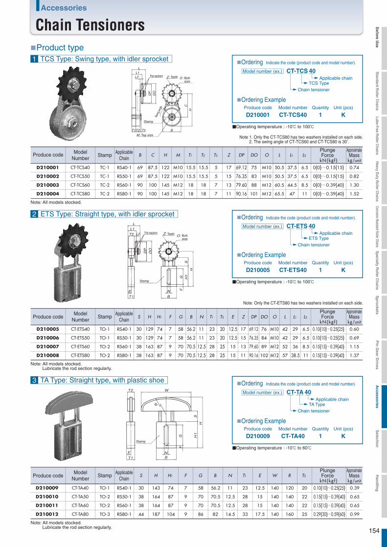
154
Befo
re Use
Standard R
oller Chains
Lube-Free Roller C
hainsH
eavy Duty R
oller Chains
Corrosion Resistant Roller ChainsS
pecialty Roller C
hainsS
pro
cketsP
in G
ear Drives
Accesso
riesS
election
Han
dlin
gAccessories
Chain Tensioners
■Ordering Indicate the code (product code and model number).
■Ordering Example
■Operating temperature : -10℃ to 100℃
■Product type
CT-TCS 40
D210001 CT-TCS40 1 K
TCS TypeChain tensioner
Produce code Model number Quantity Unit (pcs)
Applicable chain
Model number (ex.)
Note 1. Only the CT-TCS80 has two washers installed on each side. 2. The swing angle of CT-TCS60 and CT-TCS80 is 30°.
D210001
D210002
D210003
D210004
Produce code
Note: Only the CT-ETS80 has two washers installed on each side.
Note: All models stocked. Lubricate the rod section regularly.
■Ordering Indicate the code (product code and model number).
■Ordering Example
■Operating temperature : -10℃ to 60℃
Produce code Model number Quantity Unit (pcs)
Model number (ex.)
■Ordering Indicate the code (product code and model number).
■Ordering Example
■Operating temperature : -10℃ to 100℃
Produce code Model number Quantity Unit (pcs)
Model number (ex.) CT-ETS 40
D210005 CT-ETS40 1 K
ETS TypeChain tensioner
Applicable chain
CT-TA 40
D210009 CT-TA40 1 K
TA TypeChain tensioner
Applicable chain
Note: All models stocked. Lubricate the rod section regularly.
1 TCS Type: Swing type, with idler sprocket
B C H M T1 T2 T3 Z DP DO O L L1 L2
kN{kg f } kg/unit
CT-TCS40 TC-1 RS40-1 69 87.5 122 M10 15.5 15.5 5 17 69.12 75 M10 50.5 37.5 6.5 0{0}~0.15{15} 0.74
CT-TCS50 TC-1 RS50-1 69 87.5 122 M10 15.5 15.5 5 15 76.35 83 M10 50.5 37.5 6.5 0{0}~0.15{15} 0.82
CT-TCS60 TC-2 RS60-1 90 100 145 M12 18 18 7 13 79.60 88 M12 60.5 44.5 8.5 0{0}~0.39{40} 1.30
CT-TCS80 TC-2 RS80-1 90 100 145 M12 18 18 7 11 90.16 101 M12 65.5 47 11 0{0}~0.39{40} 1.52
L
Z O
L1
DP
DO
L2
T1T2 T3 B
CH
M
Flat washers : Teeth : Bolt size
Swing
angle
Stamp
: Tap size
ModelNumber
StampApplicable
Chain
PlungeForce
ApproximateMass
Note: All models stocked.
2 ETS Type: Straight type, with idler sprocket
3 TA Type: Straight type, with plastic shoe
S H H1 F G B N T1 T2 E Z DP DO O L L1 L2
CT-ETS40 TO-1 RS40-1
CT-ETS50 TO-1 RS50-1
CT-ETS60 TO-2 RS60-1
CT-ETS80 TO-2 RS80-1
S H H1 F G B N T1 E W R T2
CT-TA40 TO-1 RS40-1
CT-TA50 TO-2 RS50-1
CT-TA60 TO-2 RS60-1
CT-TA80 TO-3 RS80-1
L
Z
N
B
E
T1
O
L1
T2
DP
DO
SG
FH
1
H
L2
kN{kg f } kg/unit
ModelNumber
StampApplicable
Chain
PlungeForce
ApproximateMass
kN{kg f } kg/unit
ModelNumber
StampApplicable
Chain
PlungeForce
ApproximateMass
Flat washers : Teeth : Bolt size
Stamp
30 129 74 7 58 56.2 11 23 20 12.5 17 69.12 76 M10 42 29 6.5 0.10{10}~0.25{25} 0.60
30 129 74 7 58 56.2 11 23 20 12.5 15 76.35 84 M10 42 29 6.5 0.10{10}~0.25{25} 0.69
38 163 87 9 70 70.5 12.5 28 25 15 13 79.60 89 M12 52 36 8.5 0.15{15}~0.39{40} 1.15
38 163 87 9 70 70.5 12.5 28 25 15 11 90.16 102 M12 57 38.5 11 0.15{15}~0.39{40} 1.37
30 143 74 7 58 56.2 11 23 12.5 140 120 20 0.10{10}~0.25{25} 0.39
38 164 87 9 70 70.5 12.5 28 15 140 140 22 0.15{15}~0.39{40} 0.65
38 164 87 9 70 70.5 12.5 28 15 140 140 22 0.15{15}~0.39{40} 0.65
44 187 104 9 86 82 14.5 33 17.5 140 160 25 0.29{30}~0.59{60} 0.99
T2
E
T1N
G H1
S
H
F
B
R
W
Stamp
D210005
D210006
D210007
D210008
D210009
D210010
D210011
D210012
Produce code
Produce code
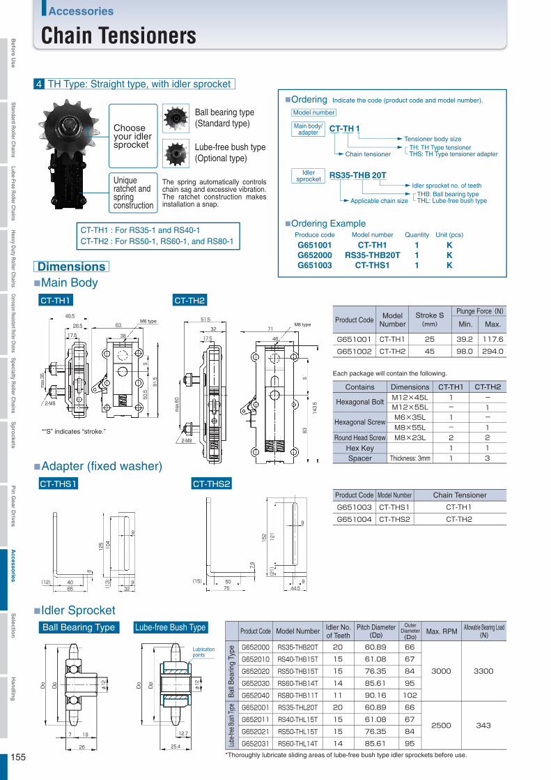
155
Accessories
Chain TensionersBefo
re Use
Standard R
oller Chains
Lube-Free Roller C
hainsH
eavy Duty R
oller Chains
Corrosion Resistant Roller ChainsS
pecialty Roller C
hainsS
pro
cketsP
in G
ear Drives
Accesso
riesS
election
Han
dlin
g
7.9
152
121
(21)
(15)
9
95075 44.5
6
125
104
(13)(12) 40 9
9
3265
φ12
26
197
Do
Dp
Do
12.7
φ12
25.4
Dp
The spring automatically controls chain sag and excessive vibration. The ratchet construction makes installation a snap.
51.5
71
46
143.5
83S
32
17.5
max.60
2-M8
M8 type
48.5
max.35
28.5
17.5
2-M8
63
38
M6 type
S50.5
91.5
CT-TH1 CT-TH2
■Ordering Indicate the code (product code and model number).
■Main Body
Ball Bearing Type Lube-free Bush Type
■Idler Sprocket
CT-TH 1
Chain tensioner
Tensioner body size
Main body/adapter
■Ordering Example
RS35-THB 20T
G651001G652000G651003
CT-TH1RS35-THB20T
CT-THS1
111
KKK
THB: Ball bearing typeTHL: Lube-free bush typeApplicable chain size
Produce code Model number Quantity Unit (pcs)
Idler sprocket no. of teeth
Idlersprocket
Hexagonal Bolt
Hexagonal Screw
Round Head ScrewHex KeySpacer
CT-TH1DimensionsContains CT-TH21-
-1
1-211
213
-1
M12×45LM12×55LM6×35LM8×55L
Thickness: 3mm
M8×23L
G651001
G651002
25
45
39.2
98.0
117.6
294.0
Min. Max.Stroke S(mm)
Plunge Force(N)
CT-TH1
CT-TH2
Product Code
CT-THS1 CT-THS2
■Adapter (fixed washer)
ModelNumber
G651003
G651004
CT-TH1
CT-TH2
Chain Tensioner
CT-THS1
CT-THS2
Product Code Model Number
G652000
G652010
G652020
G652030
G652040
G652001
G652011
G652021
G652031
20
15
15
14
11
20
15
15
14
Idler No.of Teeth
60.89
61.08
76.35
85.61
90.16
60.89
61.08
76.35
85.61
Pitch Diameter(Dp)
66
67
84
95
102
66
67
84
95
OuterDiameter(Do)
3000
2500
Max. RPM
RS35-THB20T
RS40-THB15T
RS50-THB15T
RS60-THB14T
RS80-THB11T
RS35-THL20T
RS40-THL15T
RS50-THL15T
RS60-THL14T
Product Code Model Number
3300
343
Allowable Bearing Load(N)
Lube
-free
Bus
h Typ
e
4 TH Type: Straight type, with idler sprocket
Chooseyour idlersprocket
Uniqueratchet andspringconstruction
Ball bearing type(Standard type)
Lube-free bush type(Optional type)
CT-TH1 : For RS35-1 and RS40-1CT-TH2 : For RS50-1, RS60-1, and RS80-1
Model number
TH: TH Type tensionerTHS: TH Type tensioner adapter
Dimensions
*“S” indicates “stroke.”
Each package will contain the following.
Lubricationpoints
*Thoroughly lubricate sliding areas of lube-free bush type idler sprockets before use.
Bal
l Bea
ring
Type
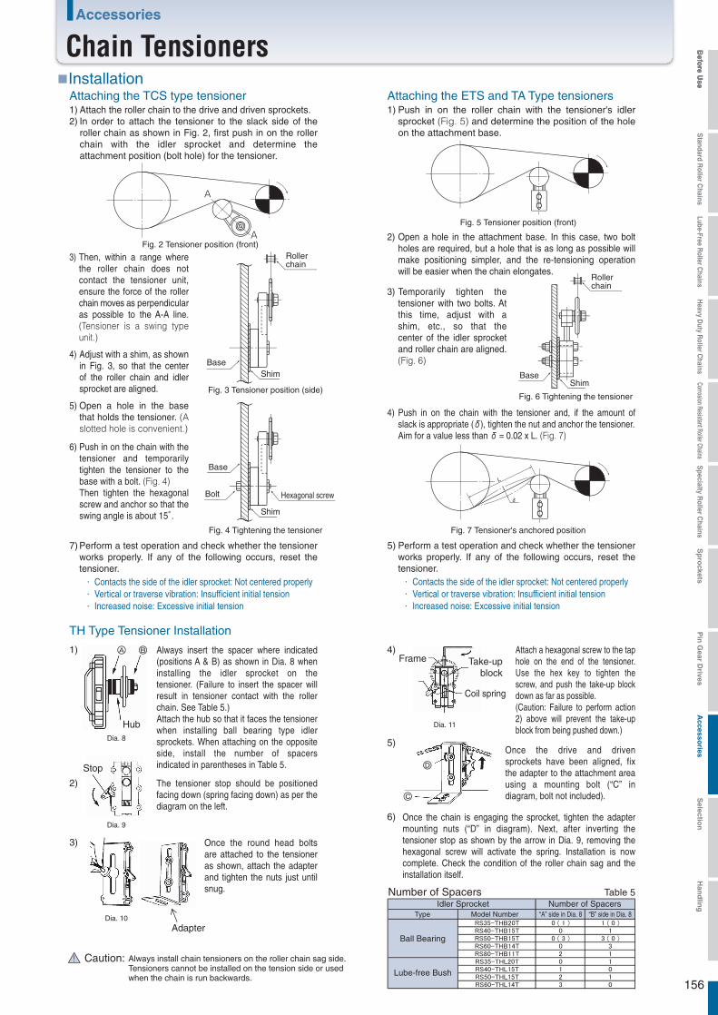
156
Befo
re Use
Standard R
oller Chains
Lube-Free Roller C
hainsH
eavy Duty R
oller Chains
Corrosion Resistant Roller ChainsS
pecialty Roller C
hainsS
pro
cketsP
in G
ear Drives
Accesso
riesS
election
Han
dlin
gAccessories
Chain Tensioners
Always insert the spacer where indicated (positions A & B) as shown in Dia. 8 when installing the idler sprocket on the tensioner. (Failure to insert the spacer will result in tensioner contact with the roller chain. See Table 5.)Attach the hub so that it faces the tensioner when installing ball bearing type idler sprockets. When attaching on the opposite side, install the number of spacers indicated in parentheses in Table 5.
Once the round head bolts are attached to the tensioner as shown, attach the adapter and tighten the nuts just until snug.
The tensioner stop should be positioned facing down (spring facing down) as per the diagram on the left.
■Installation
TH Type Tensioner Installation
Fig. 2 Tensioner position (front)
Dia. 8
Dia. 9
Dia. 10
Dia. 11
Fig. 5 Tensioner position (front)
Fig. 7 Tensioner's anchored position
Stop
Adapter
Attach a hexagonal screw to the tap hole on the end of the tensioner. Use the hex key to tighten the screw, and push the take-up block down as far as possible.(Caution: Failure to perform action 2) above will prevent the take-up block from being pushed down.)
Once the drive and driven sprockets have been aligned, fix the adapter to the attachment area using a mounting bolt (“C” in diagram, bolt not included).
Once the chain is engaging the sprocket, tighten the adapter mounting nuts (“D” in diagram). Next, after inverting the tensioner stop as shown by the arrow in Dia. 9, removing the hexagonal screw will activate the spring. Installation is now complete. Check the condition of the roller chain sag and the installation itself.
Frame
Coil spring
Take-upblock
Table 5Number of Spacers
Always install chain tensioners on the roller chain sag side.Tensioners cannot be installed on the tension side or used when the chain is run backwards.
Then, within a range where the roller chain does not contact the tensioner unit, ensure the force of the roller chain moves as perpendicular as possible to the A-A line. (Tensioner is a swing type unit.)
3)
Temporarily tighten the tensioner with two bolts. At this time, adjust with a shim, etc., so that the center of the idler sprocket and roller chain are aligned. (Fig. 6)
3)
Push in on the chain with the tensioner and, if the amount of slack is appropriate (δ), tighten the nut and anchor the tensioner.Aim for a value less than δ = 0.02 x L. (Fig. 7)
4)
Adjust with a shim, as shown in Fig. 3, so that the center of the roller chain and idler sprocket are aligned.
4)
Open a hole in the base that holds the tensioner. (A slotted hole is convenient.)
5)
Push in on the chain with the tensioner and temporarily tighten the tensioner to the base with a bolt. (Fig. 4)Then tighten the hexagonal screw and anchor so that the swing angle is about 15°.
6)
Perform a test operation and check whether the tensioner works properly. If any of the following occurs, reset the tensioner.
7)
1) 4)
5)
6)
2)
3)
Attach the roller chain to the drive and driven sprockets.In order to attach the tensioner to the slack side of the roller chain as shown in Fig. 2, first push in on the roller chain with the idler sprocket and determine the attachment position (bolt hole) for the tensioner.
1)2)
Attaching the TCS type tensionerPush in on the roller chain with the tensioner's idler sprocket (Fig. 5) and determine the position of the hole on the attachment base.
1)
Open a hole in the attachment base. In this case, two bolt holes are required, but a hole that is as long as possible will make positioning simpler, and the re-tensioning operation will be easier when the chain elongates.
2)
A
A
Fig. 3 Tensioner position (side)
Fig. 4 Tightening the tensioner
Attaching the ETS and TA Type tensioners
Fig. 6 Tightening the tensioner
Perform a test operation and check whether the tensioner works properly. If any of the following occurs, reset the tensioner.
5)
Shim
Rollerchain
Base
Shim
Base
Hexagonal screwBolt
BaseShim
Rollerchain
δ
L
Contacts the side of the idler sprocket: Not centered properlyVertical or traverse vibration: Insufficient initial tensionIncreased noise: Excessive initial tension
Contacts the side of the idler sprocket: Not centered properlyVertical or traverse vibration: Insufficient initial tensionIncreased noise: Excessive initial tension
Lube-free Bush
Hub
Caution:
Idler Sprocket Number of SpacersType Model Number “A” side in Dia. 8 “B” side in Dia. 8
Ball Bearing

157
Befo
re Use
Standard R
oller Chains
Lube-Free Roller C
hainsH
eavy Duty R
oller Chains
Corrosion Resistant Roller ChainsS
pecialty Roller C
hainsS
pro
cketsP
in G
ear Drives
Accesso
riesS
election
Han
dlin
g
Chain Connecting Tool
Tsubaki provides roller chains in either unit lengths (3048 mm) or reels. The following tools are available for cutting the chain to a desired length. See "Roller Chain and Sprocket Handling" for use.
Standard chain cutting tools cannot be used on Poly Steel Chains.A special punch and vice for Poly Steel Chains are required.
1 Chain Vise 4 Poly Steel Chain Cutting Tools
A special vice and a primary and secondary punch are required to disassemble Lambda Chains.
5 Lambda Chain Cutting Tools
This tool pulls the two ends of the chain together when installing the chain on a machine.
1 Chain Puller
2 Punch
Dimensions
L H B
RS-CV1
RS-CR1 to RS-CR3
Primary punch Secondary punch
Primary punch
Secondary punch
Rivet punch
RS-CV1 RS-CV2 RS-CV3
RS-CS-A RS-CS-B RS-CS-C
RS40 - 80RS35RS25RS15
RS40 100 65 94 - 115RS-CV2 RS40 - 160 RS40 - 100 RS40 - 100 180
605050
302020
110
3019
16.4
120 - 151RS-CV3
RS-CR1RS-CR2RS-CR3
RS80 - 240 RS80 - 160 RS80 - 100 200 170 180 - 220
BL
H
B
L
H
B
L
H
BL
H
Model NumberPrimary punch L Secondary punch L
Applicable Chain
RS-P21 65 RS15RS-P11 52 RS-P22 70 RS25
RS-P23 80 RS35
RS-P14 60 RS-P24 80 RS40 - 60RS-P15 70 RS-P25 90 RS80 - 120RS-P16 80 RS-P26 120 RS140 - 240
Model NumberRivet punch
L Applicable Chain
RS-RP01 100 RS40
RS-RP03 100 RS60RS-RP04 100 RS80
RS-RP02 100 RS50
L LL L
L
L (
MA
X )
L (
MA
X )
W W
3 Chain Breakers
L
L L
Note:
ModelNumber
Applicable Chain(Single-strand)
Applicable Chain(Single-strand & Double-strand)
RS-CS-A1 116 RS25 RS-CS-B1RS-CS-A2 119 RS35 RS-CS-C1 RS80 , 100RS-CS-A3 119 RS41 RS-CS-C2 RS120 , 140RS-CS-A4 119 RF06B RS-CS-C3 RS160 - 240
L ModelNumber
L
185 RS40 - 60222290708
Note: 1.
Note: 1.
<Cutting Tools>
RS-PC01-AST 35 20 20RS-PC02-AST 50 30 30 RS35-PC-1RS-PC03-AST 65 35 35 RS40-PC-1RS-PC04-AST 80 40 35 RS50-PC-1
L
ModelNumber
ApplicableChain
ModelNumber
ApplicableChain
H B
52 RS25-PC-1525656
RS-PC05-AST 100 45 40 56 RS60-PC-1
Chainvice
Chainvice
<Cutting Tools>
RS-LMD01-AST 65 32RS-LMD02-AST 80 40 RS50-LMD-1RS-LMD03-AST 95 48 RS60-LMD-1
RS-LMD06-AST 160 88 RS120-LMD-1
L H B
32 RS40-LMD-14048
88RS-LMD07-AST 180 98 98 RS140-LMD-1
RS-LMD04-AST 130 60 60 RS80-LMD-1RS-LMD05-AST 160 73 73 RS100-LMD-1
L W
RS-CP01 118 70 RS35 - 60RS-CP02 185 112 RS60 - 100RS-CP03 250 145 RS80 - 240
RS-CP02RS-CP03
RS-CP01
RS-CR1 K1D210013
ModelNumber
Applicable Chain
Single-strand Double-strand Triple-strand
Note: 1. The RS-P11 can be used with three sizes: RS15, RS25, and RS35.
Model number Qty UnitProduct code
Ordering Example
Ordering Specify the code (product code and model)
ModelNumber
Applicable Chain(Single-strand)
In addition to RS Roller Chains, Chain Breakers can be used with BS Roller Chains and Marine Chains. However, Chain Breakers for Marine Chains are made-to-order.
The special punch and vice are included as a set.
The special punch and vice are included as a set. Punch dimensions are the same as for the punch in section 2.
Accessories
Chain Cutting Tools

158
Befo
re Use
Standard R
oller Chains
Lube-Free Roller C
hainsH
eavy Duty R
oller Chains
Corrosion Resistant Roller ChainsS
pecialty Roller C
hainsS
pro
cketsP
in G
ear Drives
Accesso
riesS
election
Han
dlin
g
P H D T L1 L2
RS40-1 12.70 12.0 2.0 8.8 10.2 0.01RS50-1 15.0 2.4 10.7 12.3 0.02RS60-1 19.05 18.1 3.2 14.0 16.1 0.04RS80-1 25.40
15.875
24.0 4.0 17.5 20.1 0.09RS100-1 31.75 28.6 4.8 21.0 23.7 0.156RS120-1 38.10 34.4
3.975.095.967.949.54
11.11 5.6 26.05 29.55 0.264
●Allows for reliable lifting equipment using RS Roller Chain.●Designed to be stronger than RS Roller Chains, they sufficiently demonstrate RS Roller Chain's
performance when connected to a chain with appropriate clearance.
Strength when Tsubaki RS Roller Chains (except for M-type connecting links and offset links) are connected to end fitting bolts, and special connecting links are as follows.
End fixtureconnecting link
RS Roller Chain
End fixture MH
BA
30°
CO
L
CW
SW
φD
RS40EB
Applicable chainEnd fixture
1 End Fitting Bolts (for RS Roller Chains)
2 End Fitting Bolt Connecting Links (for RS Roller Chains)
L A B C M O D CW SW H
RS40EB RS40-1 38 M 8 15
RS50EB RS50-1 44 M10 19
RS60EB RS60-1 55 M12 21
RS80EB RS80-1 117.1 73 M16 28
RS100EB RS100-1 145.1 91 M20 34
RS120EB RS120-1 173.1
89.172.561.0
117.098.079.060.048.541.5
108
6.07.59.1
12.115.118.1 M24 11.15
9.587.985.995.124.00
40
11.213.817.822.627.535.5
13.017.019.024.030.035.5
6.58.0
10.013.016.019.0
0.040.070.120.270.510.86
Note: 1. SW dimensions are designed for wrench use.2. Uses old JIS B1181 (type 1) nuts and JIS B1251 spring washers.3. Black coating.
Note: 1. Contact a Tsubaki representative for connecting links and end links of differing shapes.
φD
T
L1L2
H
P
RS40-1 RS50-1 RS60-1 RS80-1 RS100-1 RS120-1
17.7{1800} 28.4{2900} 40.2{4100} 71.6{7300} 107{10900} 148{15100}
3.63{370} 6.37{650} 8.83{900} 14.7{1500} 22.6{2300} 30.4{3100}
!
RS40EB-CLRS50EB-CLRS60EB-CLRS80EB-CLRS100EB-CLRS120EB-CL
RS40EB K1D210068
Ordering : Specify the code (product code and model number)
Model number Qty UnitProduct code
Ordering Example
Model number(example)
(coarse thread)
kg/unit
ModelNumber
ApplicableChain
ApproximateWeight
kg/unit
ModelNumber
ApplicableChain
Applicable Chain
ApproximateWeight
Strength
Minimum Tensile Strength
Maximum Allowable Load
kN{kg f }
kN{kg f }
Operating temperature: -10 to 60℃ (Contact a Tsubaki representative for use in special environments.)Use the Tsubaki End Fitting Bolt Connecting Link when connecting an end fitting bolt and an RS Roller Chain. We recommended disassembling and lubricating regularly for safety.Do not use M-type connecting links for RS Roller Chains (that have a gap between the pin and connecting link plate) or offset links.Use only RS Roller Chains. These end fixtures cannot be used with Lube-Free Drive Chains, Heavy Duty Roller Chains, Super-H Roller Chains, and Ultra Super Roller Chains. (When using a Super Chain, always use a Super Chain connecting link.)Grease the surface of the connecting link pin in advance when attaching the end fitting bolt and RS Roller Chain. Take care to attach precisely and avoid twisting the chain.Attach so that there is no bending load on the end fitting bolt.Do not subject the threads or head of the end fitting bolt to impacts or cause them to become distorted.
Safety Precautions
Accessories
End Fixtures

159
Befo
re Use
Standard R
oller Chains
Lube-Free Roller C
hainsH
eavy Duty R
oller Chains
Corrosion Resistant Roller ChainsS
pecialty Roller C
hainsS
pro
cketsP
in G
ear Drives
Accesso
riesS
election
Han
dlin
g
Accessories
Automatic Lubricator for Roller Chain
The lubricator, certified with the GS mark from German TÜV safety standards, is filled with grease that satisfies international FDA and NSF (formerly USDA) standards, making it safe to use in food processing. Tsubaki auto lubricators help you increase safety in HACCP systems and contribute to your product liability countermeasures.
■Features
■Specifications
■Code chart
■Dimensions
■Ordering Please specify the code (product code and model number)
OperationOperational pressureVolumeDischarge period Operating temperature rangeOil
φ52.4
117
(3)
14
100
φ50
R1/4"
(10.5)
5
82
(45)
30
2
φ28φ5 through hole
φ30R1/4"
20
23
φ50
60
78
44
10
4.64.6
Cross-section A – A
(PT1/4)
(PT1/4)
SFM68 SFM-ST2034 SFM-ST2010
Brush (optional) Clamp (optional)
●Ordering Example
D210062 SFM68 1 KProduct Code Model No. Qty Unit (pc)
Product Code Model NumberD210062D210063D210064
SFM68SFM-ST2034SFM-ST2010
A A
1. High safety and reliability
Passed screening by TIIS, a non-governmental/non-profit organization recognized by the Minister of Health, Labor, and Welfare, and is certified as an explosion-protected electri-cal apparatus. There is no risk of explosion or fire from sparks or high temperatures from electrical apparatuses in environments with explosive gas, proving its safety.
2. Usable in explosion-proof applications
Certified IP68 as dust and water proof for use in dusty or watery environments.7. Dust and water proof
The lubricator can be installed facing up, down, or horizontally. However, if a brush is used it must be installed facing down.
6. Can be installed in any directionCompact, with a diameter of φ50 and a height of 114mm (125mL), and weighing only 190g.
5. Lightweight, compact
Automatic lubrication eliminates the need for frequent manual lubrication, which simplifies your lubrication schedule. The transparent PET plastic lubricator also features an inspection window so you can always check remaining lube and operating condition.
4. Reduced maintenance time, features an inspection window
You can easily set the service life to between 1 – 12 months with just an Allen wrench. Once set, the unit automatically operates by means of a gas generator.
3. Service life adjustable
Brush (optional)Model no.: SFM-ST2034
BodyModel no.: SFM68
Clamp (optional)Model no.: SFM-ST2010
Hs gas pressure (dry battery type)
Max. 0.3MPa
125ml
1 – 12 months, non-incremental(at an ambient temperature of 20℃)
-20 to 55℃
Food grade oil (H1)
Lubricator
Oil
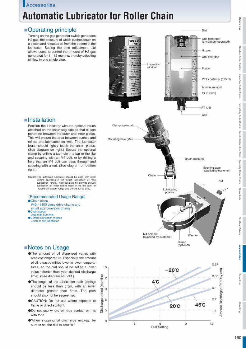
160
Befo
re Use
Standard R
oller Chains
Lube-Free Roller C
hainsH
eavy Duty R
oller Chains
Corrosion Resistant Roller ChainsS
pecialty Roller C
hainsS
pro
cketsP
in G
ear Drives
Accesso
riesS
election
Han
dlin
gAccessories
Automatic Lubricator for Roller Chain■Operating principle
■Notes on Usage
Turning on the gas generator switch generates H2 gas, the pressure of which pushes down on a piston and releases oil from the bottom of the lubricator. Setting the time adjustment dial allows users to control the amount of H2 gas generated for 1 – 12 months, thereby adjusting oil flow in one single step.
●The amount of oil dispensed varies with ambient temperature. Especially, the amount of oil released will be lower in lower tempera-tures, so the dial should be set to a lower value (shorter than your desired discharge time). (See diagram on right.)
●The length of the lubrication path (piping) should be less than 0.5m, with an inner diameter greater than 6mm. The path should also not be segmented.
●CAUTION: Do not use where exposed to flame or direct sunlight.
●Do not use where oil may contact or mix with food.
●When stopping oil discharge midway, be sure to set the dial to zero “0.”
■InstallationPosition the lubricator with the optional brush attached on the chain sag side so that oil can penetrate between the outer and inner plates. This will ensure the area between bushes and rollers are lubricated as well. The lubricator brush should lightly touch the chain plates. (See diagram on right.) Secure the optional clamp by drilling a tap hole in a bar or the like and securing with an M4 bolt, or by drilling a hole that an M4 bolt can pass through and securing with a nut. (See diagram on bottom right.)
Caution:The automatic lubricator should be used with roller chains operating in the “brush lubrication” or “drip lubrication” range. This product will not provide enough lubrication for roller chains used in the “oil bath” or “forced lubrication” range and should not be used.
15
12
9
6
3
01 3 6 9 12
Dial Setting
0.27
0.35
0.4
0.7
1.4
Gas generator(dry battery operated)
Dial
Cap
H2 gas
Gas chamber
Piston
PET container (125ml)
Aluminum label
Oil (125ml)
(PT 1/4)
Washer
Clamp(optional)
Nut
M4 bolt nut(supplied by customer)
Mounting base(supplied by customer)
●Chain sizes #40 - #100 class drive chains and small size conveyor chains●Chain speed Less than 50m/min●Current lubrication method Brush or drip lubrication
Mounting hole (M4)
Clamp (optional)
Brush (optional)
Lubricatingposition
Chain
Inspectionwindow
【Recommended Usage Range】
Dis
char
ge p
erio
d (m
onth
s)
Am
ount
Dis
char
ged
Per
Day
(m
l)
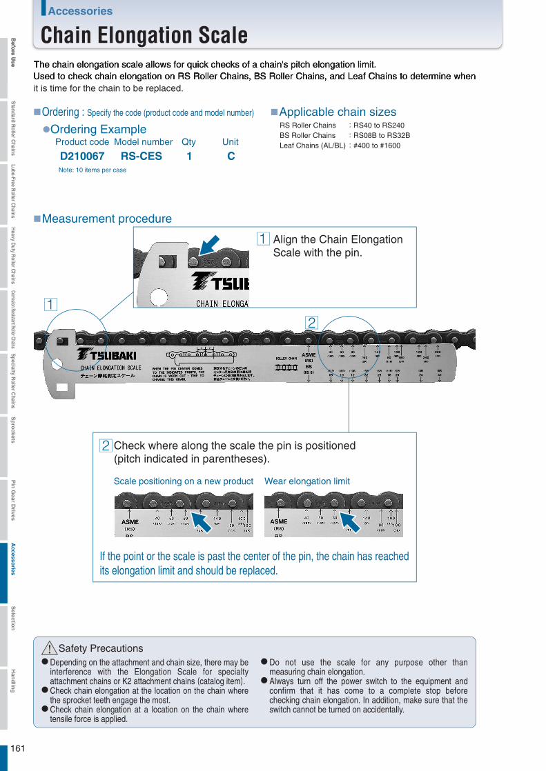
161
Befo
re Use
Standard R
oller Chains
Lube-Free Roller C
hainsH
eavy Duty R
oller Chains
Corrosion Resistant Roller ChainsS
pecialty Roller C
hainsS
pro
cketsP
in G
ear Drives
Accesso
riesS
election
Han
dlin
g
Align the Chain ElongationScale with the pin.
The chain elongation scale allows for quick checks of a chain's pitch elongation limit.Used to check chain elongation on RS Roller Chains, BS Roller Chains, and Leaf Chains to determine when it is time for the chain to be replaced.
! Safety PrecautionsDepending on the attachment and chain size, there may be interference with the Elongation Scale for specialty attachment chains or K2 attachment chains (catalog item).Check chain elongation at the location on the chain where the sprocket teeth engage the most.Check chain elongation at a location on the chain where tensile force is applied.
Do not use the scale for any purpose other than measuring chain elongation.Always turn off the power switch to the equipment and confirm that it has come to a complete stop before checking chain elongation. In addition, make sure that the switch cannot be turned on accidentally.
Check where along the scale the pin is positioned(pitch indicated in parentheses).
Scale positioning on a new product Wear elongation limit
1
1
2
2
RS-CES C1Note: 10 items per case
D210067Model number Qty UnitProduct code
Ordering Example
Ordering : Specify the code (product code and model number) Applicable chain sizes
Measurement procedure
RS Roller ChainsBS Roller Chains Leaf Chains (AL/BL)
RS40 to RS240RS08B to RS32B#400 to #1600
If the point or the scale is past the center of the pin, the chain has reachedits elongation limit and should be replaced.
Accessories
Chain Elongation Scale

Pg. 190
Pg. 191
Pg. 192
Pg. 194
Pg. 196
Pg. 197
Pg. 197
Pg. 201
Pg. 202
Pg. 163
Pg. 165
Pg. 166
Pg. 168
Pg. 171
Pg. 173
Pg. 178
Pg. 180
Pg. 181
Pg. 182
Pg. 188
Pg. 188
Pg. 189
1.
2.
3.
4.
5.
6.
7.
8.
9.
10.
11.
12.
13.
1.
2.
3.
4.
5.
6.
7.
8.
9.
Roller Chain / Sprocket Selection,Installation, and Maintenance
Selection Guide
Service Factors
Provisional Selection Chart
Selection Formulae
General Selection
Allowable Load Selection
Example of Lifting Transmissions
Calculating Moment of Inertia
Example of Shuttle Traction
Pin Gear Drive Selection
Temperature SelectionSpecial Selection Method forCorrosion Resistant Roller ChainCorrosion Resistance Guide for Drive Chains and Sprockets
How to Cut Roller Chain
How to Connect Roller Chain
Roller Chain Lubrication
Layout and Installation
Sprockets
Chain Test Run
Roller Chain Inspection
Cautions on Use in Special Environments
Troubleshooting
162
・・・・・・・・・・
・・・・・・・・・・
・・
・・・・・・・
・・・・・・・・
・・・
・・
・・
・・
・・・
・・・・・
・・
・・
・・・
・・・
・・・・
・・・・・
・・・・・・・・・・・・・・・
・・・・・・・・・・・
・・・・・
・・
・・・・・・・・・・・
Befo
re Use
Standard R
oller Chains
Lube-Free Roller C
hainsH
eavy Duty R
oller Chains
Corrosion Resistant Roller ChainsS
pecialty Roller C
hainsS
pro
cketsP
in G
ear Drives
Accesso
riesS
election
Han
dlin
g
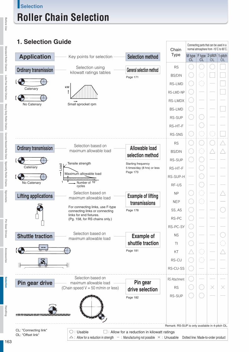
Page 171
Page 182
○
△
Page 178
Page 181
1. Selection Guide
Application Key points for selection Selection method
Ordinary transmission Selection usingkilowatt ratings tables General selection method
Catenary
No Catenary
Catenary
No Catenary
Small sprocket rpm
Ordinary transmission Selection based onmaximum allowable load Allowable load
selection method Starting frequency5 times/day (8 hrs) or lessPage 173
Load
Tensile strength
Number ofcycles
Maximum allowable load
Lifting applicationsSelection based on
maximum allowable load Example of liftingtransmissions
For connecting links, use F-typeconnecting links or connectinglinks for end fixtures.(Pg. 158, for RS chains only.)
Shuttle traction Selection based onmaximum allowable load Example of
shuttle traction
Pin gear driveSelection based on
maximum allowable load(Chain speed V = 50 m/min or less)
Pin geardrive selection
CL: "Connecting link"OL: "Offset link"
UsableAllow for a reduction in strength
Allow for a reduction in kilowatt ratings- Manufacturing not possible × Unusable Dotted line: Made-to-order product
Remark: RS-SUP is only available in 4-pitch OL.
ChainType
Connecting parts that can be used in anormal atmosphere from -10˚C to 60˚C.
M type F type 2-pitch 1-pitchCLCL
/DIN
/DIN
163
Selection
Roller Chain SelectionBefo
re Use
Standard R
oller Chains
Lube-Free Roller C
hainsH
eavy Duty R
oller Chains
Corrosion Resistant Roller ChainsS
pecialty Roller C
hainsS
pro
cketsP
in G
ear Drives
Accesso
riesS
election
Han
dlin
g

①
②
①
②
Other selections Required information for roller chain selection
Motor characteristics required for chain selection
Roller drive
Multi-shaft drive
High-speed drive
Vertical shaft drive
Right side from peak of kW ratings tables(shaded area)
Small sprocket rpm
Vertical shaft Vertical shaft
Please contact a Tsubaki representative regarding these applications.
1) Machine used2) Type of impact3) Motor type4) Rated power of motor5) Bore diameter of high-speed shaft and RPM6) Bore diameter of low-speed shaft and RPM7) Distance between shafts
When using the allowable load selection method or the pin gear drive selection method, check the following characteristics of the motor.
1) Moment of inertia of motor2) Rated torque of motor, or output shaft RPM3) Starting torque of motor4) Stalling torque of motor
Safety precautionsThe roller chain selection conditions provided here are only applicable to the selection of roller chain model and size. Please evaluate accessory devices such as safety and lubrication devices separately.
164
Befo
re Use
Standard R
oller Chains
Lube-Free Roller C
hainsH
eavy Duty R
oller Chains
Corrosion Resistant Roller ChainsS
pecialty Roller C
hainsS
pro
cketsP
in G
ear Drives
Accesso
riesS
election
Han
dlin
g
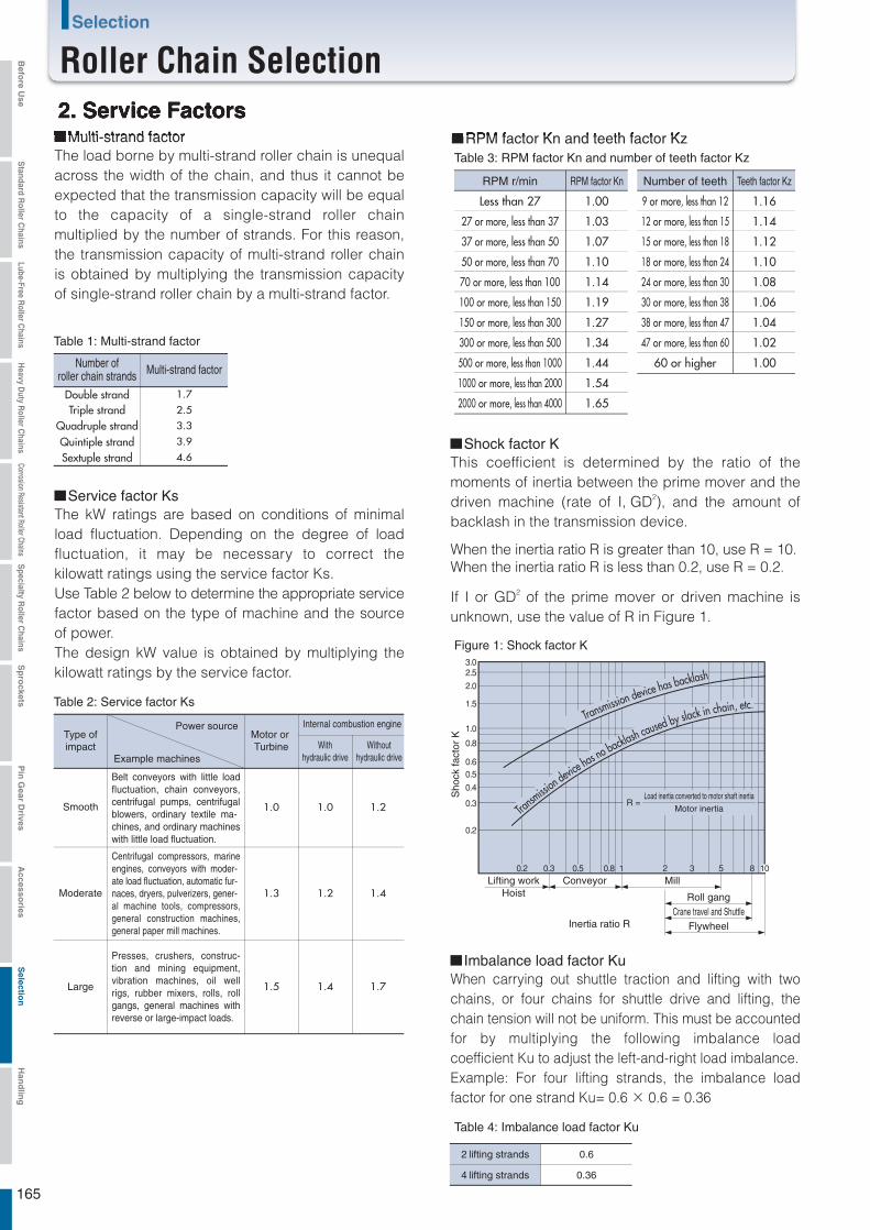
3.02.52.0
1.5
1.0
0.8
0.60.50.4
0.3
0.2
0.2 0.3 0.5 0.8 1 2 3 5 8 10
R =
Double strandTriple strand
Quadruple strandQuintiple strandSextuple strand
1.7
1.0 1.0 1.2
1.3 1.2 1.4
1.5 1.4 1.7
2.5
3.3
3.9
4.6
RPM r/min
Less than 27
27 or more, less than 37
37 or more, less than 50
50 or more, less than 70
70 or more, less than 100
100 or more, less than 150
150 or more, less than 300
300 or more, less than 500
500 or more, less than 1000
1000 or more, less than 2000
2000 or more, less than 4000
Number of teeth
9 or more, less than 12
12 or more, less than 15
15 or more, less than 18
18 or more, less than 24
24 or more, less than 30
30 or more, less than 38
38 or more, less than 47
47 or more, less than 60
60 or higher
RPM factor Kn
1.00
1.03
1.07
1.10
1.14
1.19
1.27
1.34
1.44
1.54
1.65
Teeth factor Kz
1.16
1.14
1.12
1.10
1.08
1.06
1.04
1.02
1.00
2. Service Factors
Table 1: Multi-strand factor
Table 2: Service factor Ks
Figure 1: Shock factor K
Table 4: Imbalance load factor Ku
Number ofroller chain strands
The load borne by multi-strand roller chain is unequal across the width of the chain, and thus it cannot be expected that the transmission capacity will be equal to the capacity of a single-strand roller chain multiplied by the number of strands. For this reason, the transmission capacity of multi-strand roller chain is obtained by multiplying the transmission capacity of single-strand roller chain by a multi-strand factor.
Multi-strand factor RPM factor Kn and teeth factor Kz
Multi-strand factor
Service factor Ks
Shock factor K
Type ofimpact
Smooth
Moderate
Large
Motor or Turbine With
hydraulic driveWithout
hydraulic drive
Internal combustion engine
Example machines
Power source
The kW ratings are based on conditions of minimal load fluctuation. Depending on the degree of load fluctuation, it may be necessary to correct the kilowatt ratings using the service factor Ks.Use Table 2 below to determine the appropriate service factor based on the type of machine and the source of power.The design kW value is obtained by multiplying the kilowatt ratings by the service factor.
Belt conveyors with little load fluctuation, chain conveyors, centrifugal pumps, centrifugal blowers, ordinary textile ma-chines, and ordinary machines with little load fluctuation.
Centrifugal compressors, marine engines, conveyors with moder-ate load fluctuation, automatic fur-naces, dryers, pulverizers, gener-al machine tools, compressors, general construction machines, general paper mill machines.
Presses, crushers, construc-tion and mining equipment, vibration machines, oil well rigs, rubber mixers, rolls, roll gangs, general machines with reverse or large-impact loads.
Table 3: RPM factor Kn and number of teeth factor Kz
This coefficient is determined by the ratio of the moments of inertia between the prime mover and the driven machine (rate of I, GD2), and the amount of backlash in the transmission device.
When the inertia ratio R is greater than 10, use R = 10.When the inertia ratio R is less than 0.2, use R = 0.2.
If I or GD2 of the prime mover or driven machine is unknown, use the value of R in Figure 1.
Lifting work Conveyor
Inertia ratio R
Mill
Roll gangCrane travel and Shuttle
Flywheel
Hoist
Load inertia converted to motor shaft inertiaMotor inertia
Sho
ck fa
ctor
K
Transmission device has backlash
Transm
ission devic
e has no backlash caused by slack in chain, etc.
Imbalance load factor KuWhen carrying out shuttle traction and lifting with two chains, or four chains for shuttle drive and lifting, the chain tension will not be uniform. This must be accounted for by multiplying the following imbalance load coefficient Ku to adjust the left-and-right load imbalance.Example: For four lifting strands, the imbalance load factor for one strand Ku= 0.6 × 0.6 = 0.36
2 lifting strands
4 lifting strands
0.6
0.36
165
Selection
Roller Chain SelectionBefo
re Use
Standard R
oller Chains
Lube-Free Roller C
hainsH
eavy Duty R
oller Chains
Corrosion Resistant Roller ChainsS
pecialty Roller C
hainsS
pro
cketsP
in G
ear Drives
Accesso
riesS
election
Han
dlin
g
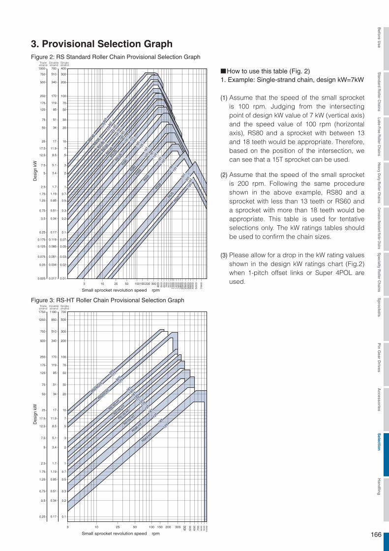
700 400
300
200
100
70
50
30
20
10
7
5
3
2
1
0.7
0.5
0.3
0.2
0.1
750
500
250
175
125
75
50
25
17.5
12.5
7.5
5
2.5
1.75
1.25
0.75
0.5
0.25
510
340
170
119
85
51
34
17
11.9
8.5
5.1
3.4
1.7
1.19
0.85
0.51
0.34
0.17
0.070.175 0.119
0.050.125 0.085
0.030.075 0.051
0.020.05 0.034
0.010.025 0.017
1000
3. Provisional Selection GraphFigure 2: RS Standard Roller Chain Provisional Selection Graph
Figure 3: RS-HT Roller Chain Provisional Selection Graph
Singlestrand
Doublestrand
Triplestrand
Des
ign
kW
Small sprocket revolution speed rpm
Small sprocket revolution speed rpm
(1)
(2)
1. Example: Single-strand chain, design kW=7kWHow to use this table (Fig. 2)
(3) Please allow for a drop in the kW rating values shown in the design kW ratings chart (Fig.2) when 1-pitch offset links or Super 4POL are used.
Assume that the speed of the small sprocket is 100 rpm. Judging from the intersecting point of design kW value of 7 kW (vertical axis) and the speed value of 100 rpm (horizontal axis), RS80 and a sprocket with between 13 and 18 teeth would be appropriate. Therefore, based on the position of the intersection, we can see that a 15T sprocket can be used.
Assume that the speed of the small sprocket is 200 rpm. Following the same procedure shown in the above example, RS80 and a sprocket with less than 13 teeth or RS60 and a sprocket with more than 18 teeth would be appropriate. This table is used for tentative selections only. The kW ratings tables should be used to confirm the chain sizes.
3 10 25 50 100 150 200 300
850 500
300
200
100
70
50
30
20
10
7
5
3
2
1
0.7
0.5
0.3
0.2
0.1
750
500
250
175
125
75
50
25
17.5
12.5
7.5
5
2.5
1.75
1.25
0.75
0.5
0.25
510
340
170
119
85
51
34
17
11.9
8.5
5.1
3.4
1.7
1.19
0.85
0.51
0.34
0.17
1250
1190 7001750
400
500
600
700
800
900
1000
Singlestrand
Doublestrand
Triplestrand
Des
ign
kW
RS240-HT
RS240-HT
20T20T17T17T
20T20T
17T17T
16T16T
13T13T
16T16T
13T13T17T17T
13T13T17T17T
13T13T
18T18T
13T13T
18T18T
13T13T
RS200-HT
RS200-HT
RS160-HT
RS160-HT
RS140-HT
RS140-HT
RS120-HT
RS120-HT
RS100-HT
RS100-HT
RS80-HT
RS80-HT
RS60-HT
RS60-HT
RS240-HT
20T17T
20T
17T
16T
13T
16T
13T17T
13T17T
13T
18T
13T
18T
13T
RS200-HT
RS160-HT
RS140-HT
RS120-HT
RS100-HT
RS80-HT
RS60-HT
166
13T13T18T18T13T13T18T18T13T13T17T17T
13T13T13T13T 17T17T13T13T 16T16T15T15T 16T16T17T17T 18T18T20T20T
17T17T20T20T
13T13T
13T13T
13T13T
20T20T
13T13T
18T18T
18T18T
18T18T
30T30T
16T16T
13T18T
RS60
13T18T
RS80
13T17T
RS100
13T13T
RS120
17T13T
RS140
16T15T
RS160
16T17T
RS180
18T20T
RS200
17T20T
RS240
13T
13T
13T
20T
13T
18T
18T
18T
30T
16T
RS50
RS40
RS35
RS25
RS25
3 10 25 50 100150200 300
400
4000
5000
7000
3000
3500
2000
2500
500
600
700
800
900
1800
1400
1600
1200
1000
1100
Befo
re Use
Standard R
oller Chains
Lube-Free Roller C
hainsH
eavy Duty R
oller Chains
Corrosion Resistant Roller ChainsS
pecialty Roller C
hainsS
pro
cketsP
in G
ear Drives
Accesso
riesS
election
Han
dlin
g

3 10 25 50 100 150 200 300
400
500
600
700
800
900
1000
Figure 5: BS/DIN Standard Roller Chain Provisional Selection Graph
850 500
300
200
100
70
50
30
20
10
7
5
3
2
1
0.7
0.5
0.3
750
500
250
175
125
75
50
25
17.5
12.5
7.5
5
2.5
1.75
1.25
0.75
510
340
170
119
85
51
34
17
11.9
8.5
5.1
3.4
1.7
1.19
0.85
0.51
1250
1190 7001750
Singlestrand
Doublestrand
Triplestrand
Des
ign
kW
Small sprocket revolution speed rpm
Small sprocket revolution speed rpm
3 10 25 50 100150 200 300
200
100
70
50
30
20
10
7
5
3
2
1
0.7
0.5
0.3
0.2
0.1
500
250
175
125
75
50
25
17.5
12.5
7.5
5
2.5
1.75
1.25
0.75
0.5
0.25
340
170
119
85
51
34
17
11.9
8.5
5.1
3.4
1.7
1.19
0.85
0.51
0.34
0.17
0.070.175 0.119
0.050.125 0.085
0.030.075 0.051
0.020.05 0.034
0.010.025 0.017
400
4000
5000
7000
3000
3500
2000
2500
500
600
700
800
900
1800
1400
1600
1200
1000
1100
Singlestrand
Doublestrand
Triplestrand
Des
ign
kW
RS240-SUP
RS240-SUP
20T20T
17T17T
20T20T
17T17T
16T16T
13T13T
16T16T
13T13T
17T17T
13T13T
17T17T
13T13T
18T18T
13T13T
RS200-SUP
RS200-SUP
RS160-SUP
RS160-SUP
RS140-SUP
RS140-SUP
RS120-SUP
RS120-SUP
RS100-SUP
RS100-SUP
RS80-SUP
RS80-SUP
RS240-SUP
20T
17T
20T
17T
16T
13T
16T
13T
17T
13T
17T
13T
18T
13T
RS200-SUP
RS160-SUP
RS140-SUP
RS120-SUP
RS100-SUP
RS80-SUP
RS56B
RS56B
20T20T
17T17T
20T20T
15T15T
20T20T
16T16T
20T20T
16T16T
16T16T
13T13T
16T16T
13T13T
17T17T
13T13T
17T17T
13T13T
26T26T
18T18T
19T19T
14T14T
16T16T
13T13T
26T26T
18T18T
21T21T
13T13T
RS48B
RS48B
RS40B
RS40B
RS32B
RS32B
RS28B
RS28B
RS24B
RS24B
RS20B
RS20B
RS16B
RS16B
RS12B
RS12B
RS10B
RS10B
RS08B
RS08B
RS06B
RS06B
RS05B
RS05B
RS56B
20T
17T
20T
15T
20T
16T
20T
16T
16T
13T
16T
13T
17T
13T
17T
13T
26T
18T
19T
14T
16T
13T
26T
18T
21T
13T
RS48B
RS40B
RS32B
RS28B
RS24B
RS20B
RS16B
RS12B
RS10B
RS08B
RS06B
RS05B
Figure 4: RS Super Roller Chain Provisional Selection Graph
167
Roller Chain Selection
Roller Chain SelectionBefo
re Use
Standard R
oller Chains
Lube-Free Roller C
hainsH
eavy Duty R
oller Chains
Corrosion Resistant Roller ChainsS
pecialty Roller C
hainsS
pro
cketsP
in G
ear Drives
Accesso
riesS
election
Han
dlin
g
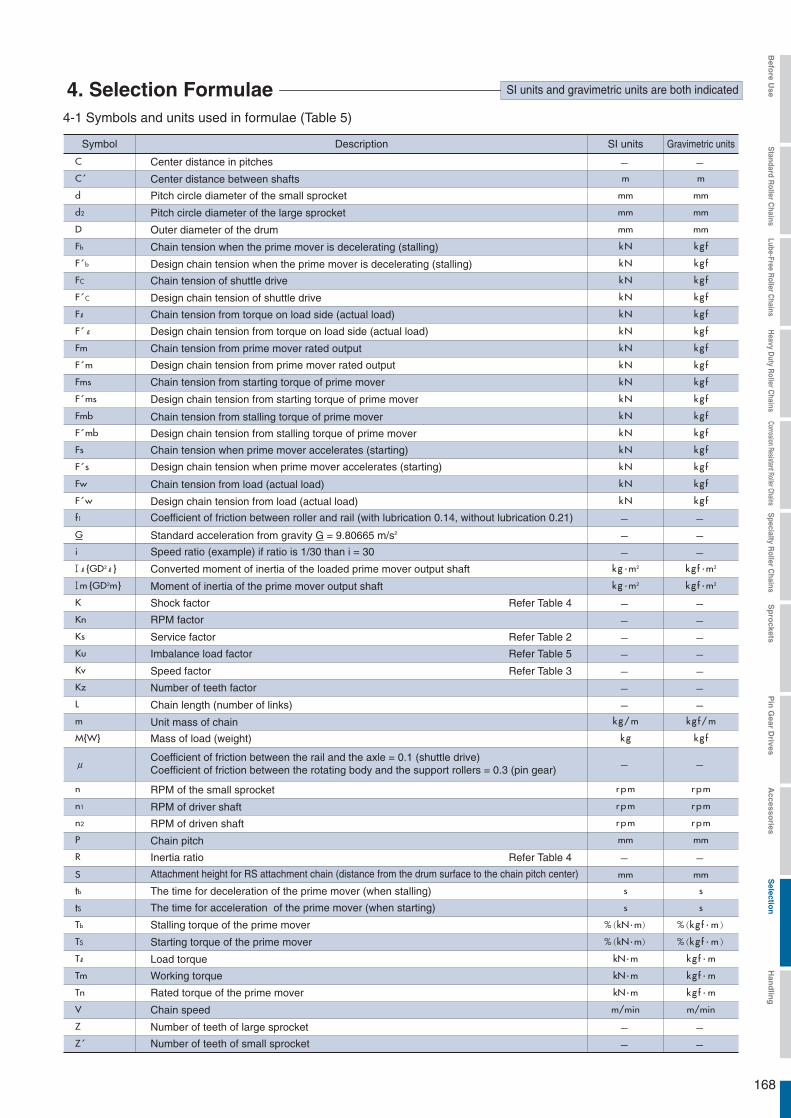
C
C m m
d mm mm
mm mm
D mm mm
Fb kN kg f
F b kN kg f
FC kN kg f
F C kN kg f
F kN kg f
F kN kg f
Fm kN kg f
F m kN kg f
Fms kN kg f
F ms kN kg f
Fmb kN kg f
F mb kN kg f
Fs kN kg f
F s kN kg f
Fw kN kg f
F w kN kg f
f1
d2
G
i
{GD2 } kg・m2 kg f・m2
m {GD2m} kg・m2 kg f・m2
K
Kz
Ks
Kn
Ku
Kv
Z
Z
P mm mm
R
S mm mm
tb s s
tS s s
Tb %(kN・m) %(kg f・m)
TS %(kN・m) %(kg f・m)
T kN・m kg f・m
Tm kN・m kg f・m
Tn kN・m kg f・m
V m/min m/min
L
m kg/m kg f/m
M{W} kg kg f
μ
n rpm rpm
n1 rpm rpm
n2 rpm rpm
4. Selection Formulae SI units and gravimetric units are both indicated
4-1 Symbols and units used in formulae (Table 5)
Symbol Description SI units Gravimetric units
Standard acceleration from gravity G = 9.80665 m/s2
Refer Table 4
Refer Table 2
Refer Table 5
Refer Table 3
Refer Table 4
Chain speed
Number of teeth of large sprocket
Number of teeth of small sprocket
Center distance in pitches
Center distance between shafts
Pitch circle diameter of the small sprocket
Pitch circle diameter of the large sprocket
Outer diameter of the drum
Chain tension when the prime mover is decelerating (stalling)
Design chain tension when the prime mover is decelerating (stalling)
Chain tension of shuttle drive
Design chain tension of shuttle drive
Chain tension from torque on load side (actual load)
Design chain tension from torque on load side (actual load)
Chain tension from prime mover rated output
Design chain tension from prime mover rated output
Chain tension from starting torque of prime mover
Design chain tension from starting torque of prime mover
Chain tension from stalling torque of prime mover
Design chain tension from stalling torque of prime mover
Chain tension when prime mover accelerates (starting)
Design chain tension when prime mover accelerates (starting)
Chain tension from load (actual load)
Design chain tension from load (actual load)
Coefficient of friction between roller and rail (with lubrication 0.14, without lubrication 0.21)
Speed ratio (example) if ratio is 1/30 than i = 30
Converted moment of inertia of the loaded prime mover output shaft
Moment of inertia of the prime mover output shaft
Shock factor
RPM factor
Service factor
Imbalance load factor
Speed factor
Number of teeth factor
Chain length (number of links)
Unit mass of chain
Mass of load (weight)
RPM of the small sprocket
RPM of driver shaft
RPM of driven shaft
Chain pitch
Inertia ratio
The time for deceleration of the prime mover (when stalling)
Attachment height for RS attachment chain (distance from the drum surface to the chain pitch center)
The time for acceleration of the prime mover (when starting)
Stalling torque of the prime mover
Starting torque of the prime mover
Load torque
Working torque
Rated torque of the prime mover
Coefficient of friction between the rail and the axle = 0.1 (shuttle drive)Coefficient of friction between the rotating body and the support rollers = 0.3 (pin gear)
168
Befo
re Use
Standard R
oller Chains
Lube-Free Roller C
hainsH
eavy Duty R
oller Chains
Corrosion Resistant Roller ChainsS
pecialty Roller C
hainsS
pro
cketsP
in G
ear Drives
Accesso
riesS
election
Han
dlin
g
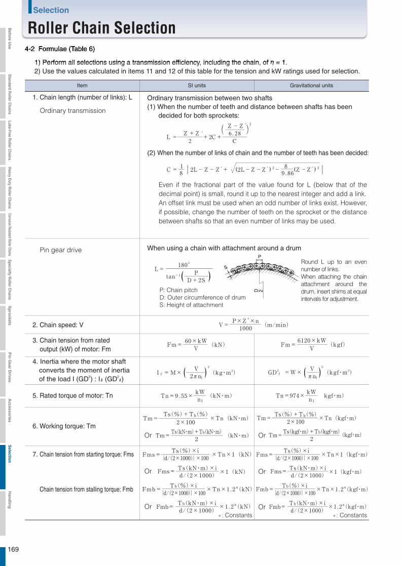
L=180°
tan-1P
D+2S( )
V=
( )
P×Z′×n1000
(m/min)
Fm=
Tn=9 . 55×
I =M×
60×kWV
(kN)
(kg・m2)
(kN・m)
V2πn1
kWn1
2
( )
Fm=
Tn=974×
GD2 =W×
Tm=
6120×kWV
(kgf)
(kgf・m2)
kgf・m)
×Tn(kgf・m)
Vπn1
kWn1
2
Ts(%)+Tb(%)2×100
Tm= (kgf・m)Ts(kgf・m)+Tb(kgf・m)
2
Tm=
×Tn×1(kN)
×Tn×1 . 2※(kN)
×1 . 2※
※
(kN)
×1(kN)
Ts(%)+Tb(%)2×100
Ts(%)×i{d/(2×1000)}×100
Tb(%)×i{d/(2×1000)}×100
Ts(kN・m)×id/(2×1000)
Tb(kN・m)×id/(2×1000)
Tm=
Fms=
Fmb=
(kN・m)
×Tn(kN・m)
Ts(kN・m)+Tb(kN・m)2
Fms=
Fmb=
×Tn×1(kgf・m)
×Tn×1 . 2※(kgf・m)
×1 . 2※(kgf・m)
×1(kgf・m)
Ts(%)×i{d/(2×1000)}×100
Tb(%)×i{d/(2×1000)}×100
Ts(kN・m)×id/(2×1000)
Tb(kN・m)×id/(2×1000)
Fms=
Fmb=
Fms=
Fmb=
L =Z +Z
+2C+
Z -Z´ 2
2 C6 . 28
C =12L-Z-Z + (2L-Z-Z ) 2-
8 (Z-Z ) 28 9 . 86{ }
4-2 Formulae (Table 6)
1) Perform all selections using a transmission efficiency, including the chain, of = 1.2) Use the values calculated in items 11 and 12 of this table for the tension and kW ratings used for selection.
Item SI units Gravitational units
Ordinary transmission between two shafts(1) When the number of teeth and distance between shafts has been decided for both sprockets:
When using a chain with attachment around a drum
(2) When the number of links of chain and the number of teeth has been decided:
1. Chain length (number of links): L
2. Chain speed: V
5. Rated torque of motor: Tn
6. Working torque: TmOr
Or
Or: Constants ※ : Constants
Or
Or
Or
3. Chain tension from rated output (kW) of motor: Fm
Even if the fractional part of the value found for L (below that of the decimal point) is small, round it up to the nearest integer and add a link.An offset link must be used when an odd number of links exist. However, if possible, change the number of teeth on the sprocket or the distance between shafts so that an even number of links may be used.
Ordinary transmission
Pin gear drive
P: Chain pitchD: Outer circumference of drumS: Height of attachment
Round L up to an even number of links.When attaching the chain attachment around the drum, insert shims at equal intervals for adjustment.
4. Inertia where the motor shaft converts the moment of inertia of the load I (GD2) : I (GD2 )
7. Chain tension from starting torque: Fms
Chain tension from stalling torque: Fmb
169
Selection
Roller Chain SelectionBefo
re Use
Standard R
oller Chains
Lube-Free Roller C
hainsH
eavy Duty R
oller Chains
Corrosion Resistant Roller ChainsS
pecialty Roller C
hainsS
pro
cketsP
in G
ear Drives
Accesso
riesS
election
Han
dlin
g

Fs=M×V
+Fw (kN )ts×60×1000
Fb=M×V
+Fw* (kN )tb×60×1000
F m=Fm×Ks×Kn×Kz (kN{kgf})
F ms=Fms×K×Kn×Kz (kN{kgf})
F mb=Fmb×K×Kn×Kz (kN{kgf})
F c=Fc×Ks×Kn×Kz (kN{kgf})
F s=Fs×Kn×Kz (kN{kgf})
F b=Fb×Kn×Kz (kN{kgf})
F w=M×Ks×Kn×Kz× (kN) F w=W( Fw)×Ks×Kn×Kz (kgf)1000G
R =IIm
1kg・m2… (I)
ts=(Im+I ) ×n1
×( s )9550× (Tm-T )
tb=(Im+I ) ×n1
×( s )9550× (Tm+T )
R =GD 2
GD2m
4kgf・m2… (GD 2)
ts=(GD 2m+GD 2 ) ×n1
( s )375× (Tm-T )
375× (Tm+T )tb=
(GD2m+GD 2 ) ×n1( s )
Fs=W×V
+Fw (kgf)ts×60×G
Fb=W×V
+Fw (kgf)tb×60×G
Item SI units Gravimetric units
Or
8. Chain tension when motor accelerates: Fs
Design chain tension
Design chain tension from motor: F'm
Design chain tension from starting torque: F'ms
Design chain tension from stalling torque: F'mb
Design chain tension from shuttle drive: F'c
Design chain tension during acceleration: F's
Design chain tension during deceleration: F'b
Design chain tension from load: F'w
If the mass M (weight W) is not known, use the rated torque Tn of the motor to calculate the shaft torque T = Tn x i kN·m {kgf·m}, and use F = 2T/d in place of W.
9. Design kW (for general selection)
11. Acceleration time of motor: ts
12. Deceleration time of motor: tb
13. Inertia ratio: R
14. Conversion of the flywheel effect (GD2) to moment of inertia ( I )
Design kW = Rated kW of motor x Ks (kW)
Chain tension when motor decelerates: Fb
10.
All chain tensions in the above formulae are the tensions when one strand of chain is used.When using two or more strands of chain, calculate the chain tension for one strand and multiply it by the imbalance load factor Ku (Table 4) for the number of strands used.
170
Befo
re Use
Standard R
oller Chains
Lube-Free Roller C
hainsH
eavy Duty R
oller Chains
Corrosion Resistant Roller ChainsS
pecialty Roller C
hainsS
pro
cketsP
in G
ear Drives
Accesso
riesS
election
Han
dlin
g
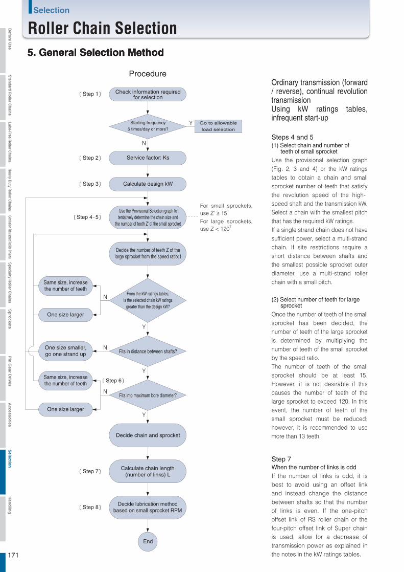
5. General Selection Method
Procedure
Step 1 Check information requiredfor selection
Service factor: Ks
Fits in distance between shafts?
Calculate design kW
One size larger
One size larger
Decide the number of teeth Z of thelarge sprocket from the speed ratio: I
Fits into maximum bore diameter?
Decide chain and sprocket
End
Same size, increasethe number of teeth
One size smaller,go one strand up
Same size, increasethe number of teeth
Calculate chain length(number of links) L
Decide lubrication methodbased on small sprocket RPM
Go to allowable
load selection
Starting frequency
6 times/day or more?
Step 2
Step 3
Step 7
Step 8
Step 6
Step 4 5
For small sprockets, use Z' ≥ 15T
For large sprockets, use Z < 120T
Use the Provisional Selection graph totentatively determine the chain size and
the number of teeth Z' of the small sprocket
From the kW ratings tables,is the selected chain kW ratings
greater than the design kW?
Steps 4 and 5(1) Select chain and number of teeth of small sprocket Use the provisional selection graph (Fig. 2, 3 and 4) or the kW ratings tables to obtain a chain and small sprocket number of teeth that satisfy the revolution speed of the high-speed shaft and the transmission kW. Select a chain with the smallest pitch that has the required kW ratings.If a single strand chain does not have sufficient power, select a multi-strand chain. If site restrictions require a short distance between shafts and the smallest possible sprocket outer diameter, use a multi-strand roller chain with a small pitch.
(2) Select number of teeth for large sprocketOnce the number of teeth of the small sprocket has been decided, the number of teeth of the large sprocket is determined by multiplying the number of teeth of the small sprocket by the speed ratio.The number of teeth of the small sprocket should be at least 15. However, it is not desirable if this causes the number of teeth of the large sprocket to exceed 120. In this event, the number of teeth of the small sprocket must be reduced; however, it is recommended to use more than 13 teeth.
Step 7When the number of links is oddIf the number of links is odd, it is best to avoid using an offset link and instead change the distance between shafts so that the number of links is even. If the one-pitch offset link of RS roller chain or the four-pitch offset link of Super chain is used, allow for a decrease of transmission power as explained in the notes in the kW ratings tables.
Ordinary transmission (forward / reverse), continual revolution transmissionUsing kW ratings tables, infrequent start-up
171
Selection
Roller Chain SelectionBefo
re Use
Standard R
oller Chains
Lube-Free Roller C
hainsH
eavy Duty R
oller Chains
Corrosion Resistant Roller ChainsS
pecialty Roller C
hainsS
pro
cketsP
in G
ear Drives
Accesso
riesS
election
Han
dlin
g
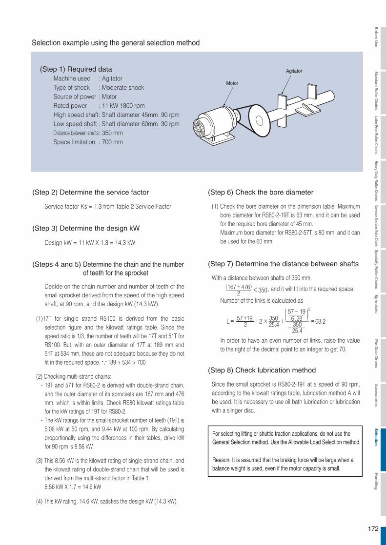
Service factor Ks = 1.3 from Table 2 Service Factor
Design kW = 11 kW X 1.3 = 14.3 kW
L= +2 × + =68.235025.4
2 25.4350
2( )57-196.2857+19
<3502(167+476)
Reason: It is assumed that the braking force will be large when abalance weight is used, even if the motor capacity is small.
Selection example using the general selection method
: Agitator: Moderate shock: Motor: 11 kW 1800 rpm: Shaft diameter 45mm 90 rpm: Shaft diameter 60mm 30 rpm: 350 mm: 700 mm
Machine usedType of shockSource of powerRated powerHigh speed shaftLow speed shaftDistance between shaftsSpace limitation
(Step 1) Required data
(Step 2) Determine the service factor
(Step 3) Determine the design kW
(Steps 4 and 5) Determine the chain and the numberof teeth for the sprocket
Decide on the chain number and number of teeth of the small sprocket derived from the speed of the high speed shaft, at 90 rpm, and the design kW (14.3 kW).
(1)17T for single strand RS100 is derived from the basic selection figure and the kilowatt ratings table. Since the speed ratio is 1/3, the number of teeth will be 17T and 51T for RS100. But, with an outer diameter of 17T at 189 mm and 51T at 534 mm, these are not adequate because they do not fit in the required space. 189 + 534 > 700
(2) Checking multi-strand chains:19T and 57T for RS80-2 is derived with double-strand chain, and the outer diameter of its sprockets are 167 mm and 476 mm, which is within limits. Check RS80 kilowatt ratings table for the kW ratings of 19T for RS80-2.The kW ratings for the small sprocket number of teeth (19T) is 5.06 kW at 50 rpm, and 9.44 kW at 100 rpm. By calculating proportionally using the differences in their tables, drive kW for 90 rpm is 8.56 kW.
(3) This 8.56 kW is the kilowatt rating of single-strand chain, and the kilowatt rating of double-strand chain that will be used is derived from the multi-strand factor in Table 1.8.56 kW X 1.7 = 14.6 kW
(4) This kW rating, 14.6 kW, satisfies the design kW (14.3 kW).
(Step 6) Check the bore diameter
(1) Check the bore diameter on the dimension table. Maximum bore diameter for RS80-2-19T is 63 mm, and it can be used for the required bore diameter of 45 mm.Maximum bore diameter for RS80-2-57T is 80 mm, and it can be used for the 60 mm.
(Step 8) Check lubrication method
Since the small sprocket is RS80-2-19T at a speed of 90 rpm, according to the kilowatt ratings table, lubrication method A will be used. It is necessary to use oil bath lubrication or lubrication with a slinger disc.
(Step 7) Determine the distance between shafts
With a distance between shafts of 350 mm,
, and it will fit into the required space.
Number of the links is calculated as
In order to have an even number of links, raise the value to the right of the decimal point to an integer to get 70.
For selecting lifting or shuttle traction applications, do not use the General Selection method. Use the Allowable Load Selection method.
Motor
Agitator
172
Befo
re Use
Standard R
oller Chains
Lube-Free Roller C
hainsH
eavy Duty R
oller Chains
Corrosion Resistant Roller ChainsS
pecialty Roller C
hainsS
pro
cketsP
in G
ear Drives
Accesso
riesS
election
Han
dlin
g

(1)For transmission with large shocks and other extreme conditions, in particular large-load transmission and transmission where a thrust load may operate, use F-type connecting links or two-pitch offset links.
(2)When using a one-pitch offset link, or a Super Chain 4 pitch offset link, make the following allowances for strength with respect to the maximum allowable loadM-type CL*: 100%F-type CL: 100%Two-pitch offset link: 100%(Reference)One-pitch offset link: 65%4 pitch offset link: 90%(Super Chain single strand)One and two-pitch offset link: 60%(BS/DIN Chain)
(3)There is a possibility that the rim or boss of commercially available cast iron sprockets are not strong enough for the high tension of Super Chain, Super-H Roller Chain, and Ultra Super Chain. A type, B type, and C type RS sprockets are suitably strong.(Use SS400, S35C, SC450, etc.)
(4)For high-speed sprockets, use a sprocket with hardened tooth tips.
(5)Be sure to lubricate roller chain, as the bearing pressure rises very high.
* Allow an 80% reduction for M type connecting links for RS15, 25, 37, 38, 41, BF25-H, 05B, 06B, 48B, 56B and RS-KT Corrosion Resistant roller chain.
Procedures
Confirm data required for selection
Step 1
Step 2Step 2
Step 3
Check motor characteristics
Start frequencyOver 6 times/day (8h)
With cushionedstart and stop
Calculate from load Calculate from load
Check the mass M(weight W) of the load
Service factor: Ks
RPM: Kn
Number of teeth factor: Kz
RPM: Kn
Number of teeth factor: Kz
Calculate designchain tension: F'w
Calculate fromacceleration/deceleration time
Acceleration time: ts Deceleration time: tb
Calculate chaintension: Fs
Calculate chaintension: Fb
Use the larger value
Use the larger value
Use the larger value
Calculate designchain tension: F's (F'b)
Step 4
Calculate from inertia ratio R
Shock factor: K
Starting torque: Ts Stalling torque: Tb
Calculate chaintension: Fms
Calculate chaintension: Fmb
Calculate designchain tension: F'ms (Fmb)
Decide the chain size so that the larger of F'w,F's (F'b) and F'ms (F'mb) ≦ maximum allowable tension
Decide small sprocket: Z', and large sprocket: Z
Check distance between shafts
Check maximum shaft hole diameter
Decide chain and sprocket
Calculate chain length (number of links) L
Decide on lubrication method from the smallsprocket rotation speed, referring to the kilowatt
ratings table of a chain with identical pitch
End
Selection Speed Limit
Pitch mmSpeed limit
m/min
The speed limit for PolySteel Chain is 70 m/min.
The following selection method uses maximum allowable load for products with no kilowatt ratings tables, or for products operated at low speeds with frequent stops.
6. Allowable Load Selection Method
173
Selection
Roller Chain SelectionBefo
re Use
Standard R
oller Chains
Lube-Free Roller C
hainsH
eavy Duty R
oller Chains
Corrosion Resistant Roller ChainsS
pecialty Roller C
hainsS
pro
cketsP
in G
ear Drives
Accesso
riesS
election
Han
dlin
g

Rated torque Tn=9.55× n1
=9.55× 1800
=0.058 (kN・m)
Starting torque Ts=Tn×2=0.058×2=0.116 (kN・m)Stalling torque Tb=Tn×2.1=0.058×2.1=0.122 (kN・m)Motor moment of inertia Im=0.088 (kg・m
2)
Driven shaft revolution
n2=Speed of transport×(External diameter of conveyor roller+2×Belt thickness)×π
=30×(380+20)×π
=23.9 (r/min)
Drive shaft revolution
n=Motor rotation/i= 50
=36 (r/min)
Chain reducer ratio= 36
= 1.51
If the driven sprocket d2=400mmChain tension Fw=Conveyor roller rotation torque×1000×
d2 = 3.3×1000×
400 =16.5 (kN)
Tentatively select the chain.
With moderate shock・・・・・・・Usage factor Ks=1.3Tentative design chain tension = Fw×Ks=16.5×1.3=21.5 (kN) Tentatively select RS120-1 with a maximum allowable load of
30.4 kN.
11kW
1000
1000
1800
23.9 1
2
2
Rated torque Tn=9.74× n1
=9.74× 1800
=5.95 (kgf・m)
Starting torque Ts=Tn×2=5.95×2=11.9 (kgf・m)Stalling torque Tb=Tn×2.1=5.95×2.1=12.5 (kgf・m)GD
2 of the motor GD
2m=0.352 (kgf・m
2)
Driven shaft revolution
n2=Speed of transport×(External diameter of conveyor roller+2×Belt thickness)×π
=30×(380+20)×π
=23.9 (r/min)
Drive shaft revolution
n=Motor rotation/i= 50
=36 (r/min)
Chain reducer ratio= 36
= 1.51
If the driven sprocket d2=400mmChain tension Fw=Conveyor roller rotation torque×1000×
d2 = 337×1000×
400 =1690 (kgf)
Tentatively select the chain.
With moderate shock・・・・・・・Usage factor Ks=1.3Tentative design chain tension = Fw×Ks=1690×1.3=2200 (kgf) Tentatively select RS120-1 with a maximum allowable load of
3100 kgf.
11kW
1000
1000
1800
23.9 1
2
2
Sprocket outer diameter ≦ 400 mm(Distancebetween shafts)
Reducer ratioi = 50 Drive Roller Chain
ConditionsMachine used: Conveyor driveChain load M: 6000 kgChain speed: 30 m/minConveyor roller diameter: 380 mmBelt thickness: 10 mmConveyor roller rotation torque: 3.3 kN/m (337 kg/m)Motor : 11 kW n1 = 1800 rpm Start torque 200% Stop (maximum) torque 210% Moment of inertia 0.088 kg/m2
(GD2 0.352 kgf/m2)
Reducer ratio: 1/50 (i = 50)Drive shaft diameter: 66 mmDriven shaft diameter: 94 mmDistance b/w shafts: 500 mmDriven sprocket diameter ≦ 400 mmStarting frequency: 10 times/dayType of shock: Moderate shockSoft start/stop: None
SI Units {Gravimetric units}
(Step 1) Check motor characteristics
(Step 2) Calculate from load
(Step 1) Check motor characteristics
(Step 2) Calculate from load
174
Befo
re Use
Standard R
oller Chains
Lube-Free Roller C
hainsH
eavy Duty R
oller Chains
Corrosion Resistant Roller ChainsS
pecialty Roller C
hainsS
pro
cketsP
in G
ear Drives
Accesso
riesS
election
Han
dlin
g
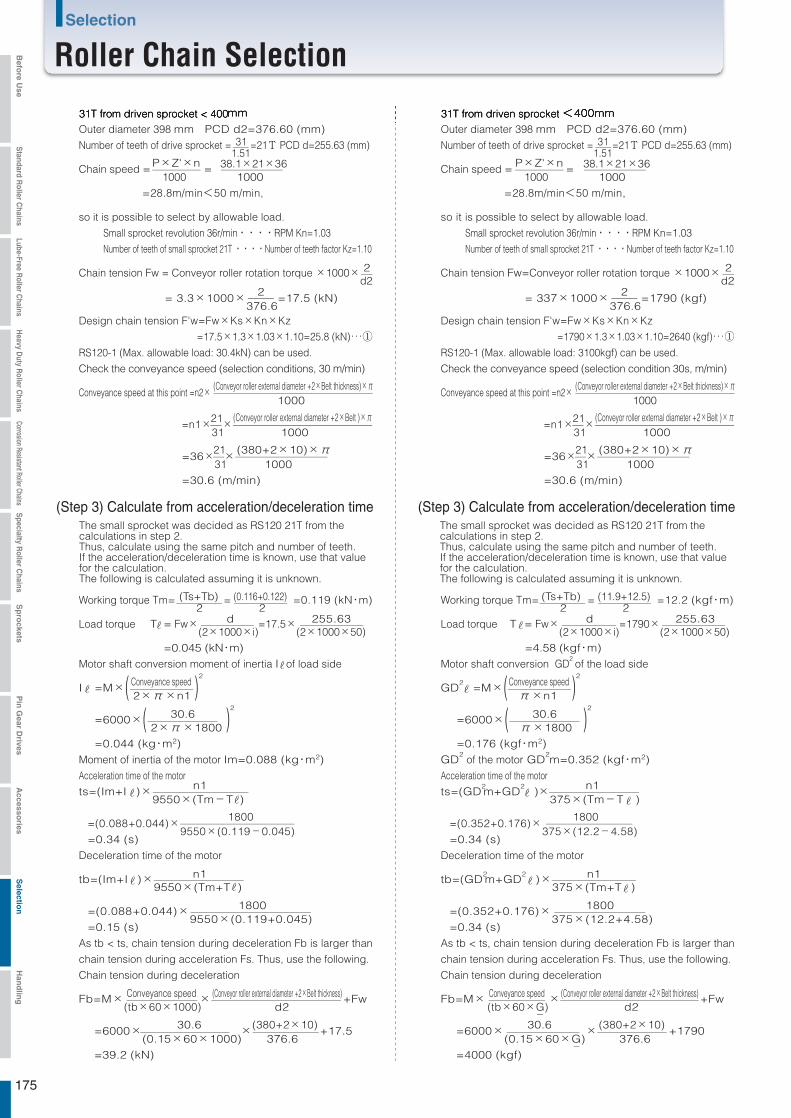
31T from driven sprocket < 400mmOuter diameter 398 mm PCD d2=376.60 (mm)Number of teeth of drive sprocket =
1.51=21T PCD d=255.63 (mm)
Chain speed = 1000
= 1000
=28.8m/min<50 m/min,
so it is possible to select by allowable load.
Small sprocket revolution 36r/min・・・・RPM Kn=1.03 Number of teeth of small sprocket 21T ・・・・Number of teeth factor Kz=1.10
Chain tension Fw = Conveyor roller rotation torque ×1000×d2
Design chain tension F'w=Fw×Ks×Kn×Kz =17.5×1.3×1.03×1.10=25.8 (kN)・・・①RS120-1 (Max. allowable load: 30.4kN) can be used.
Check the conveyance speed (selection conditions, 30 m/min)
Conveyance speed at this point =n2× 1000
=n1×31×
1000
=36×31×
1000 =30.6 (m/min)
Working torque Tm= 2
= 2
=0.119 (kN・m)
Load torque T = Fw×(2×1000×i)
=17.5×(2×1000×50)
=0.045 (kN・m) Motor shaft conversion moment of inertia I of load side
I =M×( 2×π×n1 )2
=6000×( 2×π×1800 )2
=0.044 (kg・m2)Moment of inertia of the motor Im=0.088 (kg・m2)Acceleration time of the motor
ts=(Im+I )×9550×(Tm-T )
=(0.088+0.044)×9550×(0.119-0.045)
=0.34 (s)Deceleration time of the motor
tb=(Im+I )×9550×(Tm+T )
=(0.088+0.044)×9550×(0.119+0.045)
=0.15 (s)As tb < ts, chain tension during deceleration Fb is larger than
chain tension during acceleration Fs. Thus, use the following.
Chain tension during deceleration
Fb=M×(tb×60×1000)
× d2
+Fw
=6000×(0.15×60×1000)
× 376.6
+17.5
=39.2 (kN)
31
P×Z'×n 38.1×21×36 P×Z'×n 38.1×21×36
2
2
21
(Conveyor roller external diameter +2×Belt thickness)×π
(Conveyor roller external diameter +2×Belt )×π
21 (380+2×10)×π
(Ts+Tb) (0.116+0.122)
d 255.63
Conveyance speed
30.6
n1
1800
n1
1800
Conveyance speed (Conveyor roller external diameter +2×Belt thickness)
30.6 (380+2×10)
31T from driven sprocket <400mmOuter diameter 398 mm PCD d2=376.60 (mm)Number of teeth of drive sprocket =
1.51=21T PCD d=255.63 (mm)
Chain speed = 1000
= 1000
=28.8m/min<50 m/min,
so it is possible to select by allowable load.
Small sprocket revolution 36r/min・・・・RPM Kn=1.03 Number of teeth of small sprocket 21T ・・・・Number of teeth factor Kz=1.10
Chain tension Fw=Conveyor roller rotation torque ×1000×d2
Design chain tension F'w=Fw×Ks×Kn×Kz =1790×1.3×1.03×1.10=2640 (kgf)・・・①RS120-1 (Max. allowable load: 3100kgf) can be used.
Check the conveyance speed (selection condition 30s, m/min)
Conveyance speed at this point =n2× 1000
=n1×31×
1000
=36×31×
1000 =30.6 (m/min)
Working torque Tm= 2
= 2
=12.2 (kgf・m)
Load torque T = Fw×(2×1000×i)
=1790×(2×1000×50)
=4.58 (kgf・m)Motor shaft conversion GD
2 of the load side
GD2 =M×( π×n1 )
2
=6000×( π×1800 )2
=0.176 (kgf・m2)GD
2 of the motor GD
2m=0.352 (kgf・m2)
Acceleration time of the motor
ts=(GD2m+GD
2 )×
375×(Tm-T )
=(0.352+0.176)×375×(12.2-4.58)
=0.34 (s)Deceleration time of the motor
tb=(GD2m+GD
2 )×
375×(Tm+T )
=(0.352+0.176)×375×(12.2+4.58)
=0.34 (s)As tb < ts, chain tension during deceleration Fb is larger than
chain tension during acceleration Fs. Thus, use the following.
Chain tension during deceleration
Fb=M× (tb×60×G)
× d2
+Fw
=6000×(0.15×60×G)
× 376.6
+1790
=4000 (kgf)
31
2
2
21
21 (380+2×10)×π
(Ts+Tb) (11.9+12.5)
d 255.63
Conveyance speed
30.6
n1
1800
n1
1800
30.6 (380+2×10)
= 3.3×1000×376.6
=17.5 (kN) = 337×1000×376.6
=1790 (kgf)
(Step 3) Calculate from acceleration/deceleration time (Step 3) Calculate from acceleration/deceleration timeThe small sprocket was decided as RS120 21T from thecalculations in step 2. Thus, calculate using the same pitch and number of teeth.If the acceleration/deceleration time is known, use that value for the calculation. The following is calculated assuming it is unknown.
The small sprocket was decided as RS120 21T from thecalculations in step 2. Thus, calculate using the same pitch and number of teeth.If the acceleration/deceleration time is known, use that value for the calculation. The following is calculated assuming it is unknown.
(Conveyor roller external diameter +2×Belt thickness)×π
(Conveyor roller external diameter +2×Belt )×π
Conveyance speed (Conveyor roller external diameter +2×Belt thickness)
175
Selection
Roller Chain SelectionBefo
re Use
Standard R
oller Chains
Lube-Free Roller C
hainsH
eavy Duty R
oller Chains
Corrosion Resistant Roller ChainsS
pecialty Roller C
hainsS
pro
cketsP
in G
ear Drives
Accesso
riesS
election
Han
dlin
g

Design chain tension
F'b=Fb×Kn×Kz=39.2×1.03×1.10=44.4(kN)・・・・・②RS120-2 (maximum allowable load 51.7 kN) or RS120-SUP-2
(maximum allowable load 66.7 kN) can be used because F'b=44.4(kN).
Considering RS140 18T (outer diameter 279 mm d = 255.98) and 27T
(outer diameter 407 mm d2 = 382.88) with similar PCD results conflict with the
driven sprocket external diameter ≦ 400 mm, they cannot be used.
Chain reduction ratio becomes 23.9
from the required 18
, and
conveyance speed =30× 23.9
× 26
=31.3m/min,
but upon examination 26T (outer diameter 393mm d2=368.77)
② is F'b=46.3(kN)
RS140-1 cannot be used because its maximum allowable load is 40.2kN.
RS140-SUP-1 can be used because its maximum allowable load is 53.9kN.
Since the sprocket bore diameter of 18T is up to 89 mm, and for 26T is up
to 103 mm, it can be used with a drive shaft diameter of 66 mm and driven
shaft diameter of 94 mm.
With the distance between shafts at 500 mm, a sprocket with 18T
(d=255.98) and 26T (d2=368.77) can be used.
Number of links will be 46 links.
Lubrication for RS140-SUP-1 should be oil bath or lubrication using a
slinger disc as per the kilowatt ratings table.
Inertia ratio R= Im
= 0.088
=0.5
There is clearance in the drive equipment ・・・・Shock factor K=1.0
Starting torque Ts=0.116 (kN・m)Chain tension from starting torque
Fms=Ts×i×1000×d
= 0.116×50×1000×255.63
=45.4 (kN)
Stalling torque Tb=0.122 (kN・m)Chain tension from stalling torque
Fmb=Tb×i×1.2×1000×d
= 0.122×50×1.2×1000×255.63
=57.3 (kN)
Since Fmb>Fms, use the larger Fmb.
Design chain tension
F'mb=Fmb×K×Kn×Kz=57.3×1.0×1.03×1.10=64.9 (kN) ・・・・・③
Comparing ①, ②, and ③, ③ is the largest.
Since F'mb=64.3 (kN), RS120-3 (maximum allowable load
76.0 kN) or RS120-SUP-2 (maximum allowable load 66.7 kN) is usable.
With the distance between shafts at 500mm, a sprocket with
21T (d=255.63) and 31T (d2=376.60) can be used.
Number of links will be 54 links.
Lubrication for both RS120-1 and RS120-SUP-1 should be oil
bath or lubrication by slinger disc as per the kilowatt ratings
table.
36 26
36 18
I 0.044
2
2
2
2
Design chain tension
F'b=Fb×Kn×Kz=4000×1.03×1.10=4530(kgf)・・・・・②RS120-2 (maximum allowable load 5270 kgf) or RS120-SUP-2
(maximum allowable load 6800kN) can be used because F'b=4530(kgf).
Considering RS140 18T (outer diameter 279 mm d = 255.98) and 27T
(outer diameter 407 mm d2 = 382.88) with similar PCD results conflict with the
driven sprocket external diameter ≦ 400 mm, they cannot be used.
Chain reduction ratio becomes 23.9
from the required 18
, and
conveyance speed =30× 23.9
× 26
=31.3m/min,
but upon examination 26T (outer diameter 393mm d2=368.77)
② is F'b=4720(kgf)
RS140-1 cannot be used because its maximum allowable load is 4100kgf.
RS140-SUP-1 can be used because its maximum allowable load is 5500kgf.
Since the sprocket bore diameter of 18T is up to 89 mm, and for 26T is up
to 103 mm, it can be used with a drive shaft diameter of 66 mm and driven
shaft diameter of 94 mm.
With the distance between shafts at 500 mm, a sprocket with 18T
(d=255.98) and 26T (d2=368.77) can be used.
Number of links will be 46 links.
Lubrication for RS140-SUP-1 should be oil bath or lubrication using a
slinger disc as per the kilowatt ratings table.
Inertia ratio R= GD
2m
=0.352
=0.5
There is clearance in the drive equipment ・・・・Shock factor K=1.0
Starting torque Ts=11.9 (kgf・m)Chain tension from starting torque
Fms=Ts×i×1000×d
= 11.9×50×1000×255.63
=4660 (kgf)
Stalling torque Tb=12.5 (kgf・m)Chain tension from stalling torque
Fmb=Tb×i×1.2×1000×d
= 12.5×50×1.2×1000×255.63
=5870 (kgf)
Since Fmb>Fms, use the larger Fmb.
Design chain tension
F'mb=Fmb×K×Kn×Kz=5870×1.0×1.03×1.10=6650 (kgf) ・・・・・③
Comparing ①, ②, and ③, ③ is the largest.
Since F'mb=6650 (kgf), RS120-3 (maximum allowable load
7750 kgf) or RS120-SUP-2 (maximum allowable load 6800 kgf) is usable.
With the distance between shafts at 500mm, a sprocket with
21T (d=255.63) and 31T (d2=376.60) can be used.
Number of links will be 54 links.
Lubrication for both RS120-1 and RS120-SUP-1 should be oil
bath or lubrication by slinger disc as per the kilowatt ratings
table.
36 26
36 18
GD2
0.176
2
2
2
2
(Step 4) Calculate from inertia ratio R (Step 4) Calculate from inertia ratio R
176
Befo
re Use
Standard R
oller Chains
Lube-Free Roller C
hainsH
eavy Duty R
oller Chains
Corrosion Resistant Roller ChainsS
pecialty Roller C
hainsS
pro
cketsP
in G
ear Drives
Accesso
riesS
election
Han
dlin
g
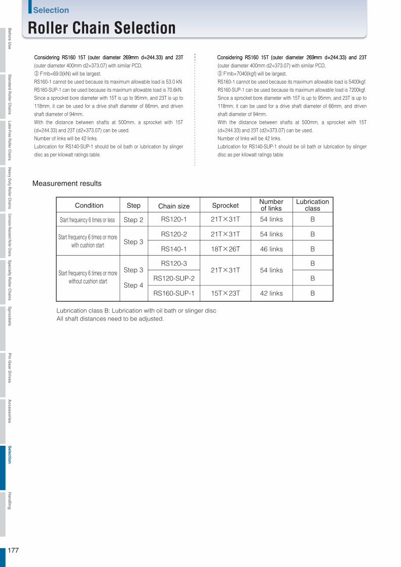
Considering RS160 15T (outer diameter 269mm d=244.33) and 23T
(outer diameter 400mm d2=373.07) with similar PCD,
③ F'mb=69.0(kN) will be largest.
RS160-1 cannot be used because its maximum allowable load is 53.0 kN.
RS160-SUP-1 can be used because its maximum allowable load is 70.6kN.
Since a sprocket bore diameter with 15T is up to 95mm, and 23T is up to
118mm, it can be used for a drive shaft diameter of 66mm, and driven
shaft diameter of 94mm.
With the distance between shafts at 500mm, a sprocket with 15T
(d=244.33) and 23T (d2=373.07) can be used.
Number of links will be 42 links.
Lubrication for RS140-SUP-1 should be oil bath or lubrication by slinger
disc as per kilowatt ratings table.
Considering RS160 15T (outer diameter 269mm d=244.33) and 23T
(outer diameter 400mm d2=373.07) with similar PCD,
③ F'mb=7040(kgf) will be largest.
RS160-1 cannot be used because its maximum allowable load is 5400kgf.RS160-SUP-1 can be used because its maximum allowable load is 7200kgf.Since a sprocket bore diameter with 15T is up to 95mm, and 23T is up to
118mm, it can be used for a drive shaft diameter of 66mm, and driven
shaft diameter of 94mm.
With the distance between shafts at 500mm, a sprocket with 15T
(d=244.33) and 23T (d2=373.07) can be used.
Number of links will be 42 links.
Lubrication for RS140-SUP-1 should be oil bath or lubrication by slinger
disc as per kilowatt ratings table.
Measurement results
Condition Step Chain size Sprocket Numberof links
Lubricationclass
Start frequency 6 times or less Step 2 54 links
54 links
54 links
Start frequency 6 times or morewith cushion start Step 3
Step 3
Step 4
46 links
Start frequency 6 times or morewithout cushion start
42 links
21T×31T
21T×31T
18T×26T
21T×31T
15T×23T
B
B
B
B
B
B
RS120-1
RS120-2
RS140-1
RS120-3
RS120-SUP-2
RS160-SUP-1
Lubrication class B: Lubrication with oil bath or slinger discAll shaft distances need to be adjusted.
177
Selection
Roller Chain SelectionBefo
re Use
Standard R
oller Chains
Lube-Free Roller C
hainsH
eavy Duty R
oller Chains
Corrosion Resistant Roller ChainsS
pecialty Roller C
hainsS
pro
cketsP
in G
ear Drives
Accesso
riesS
election
Han
dlin
g
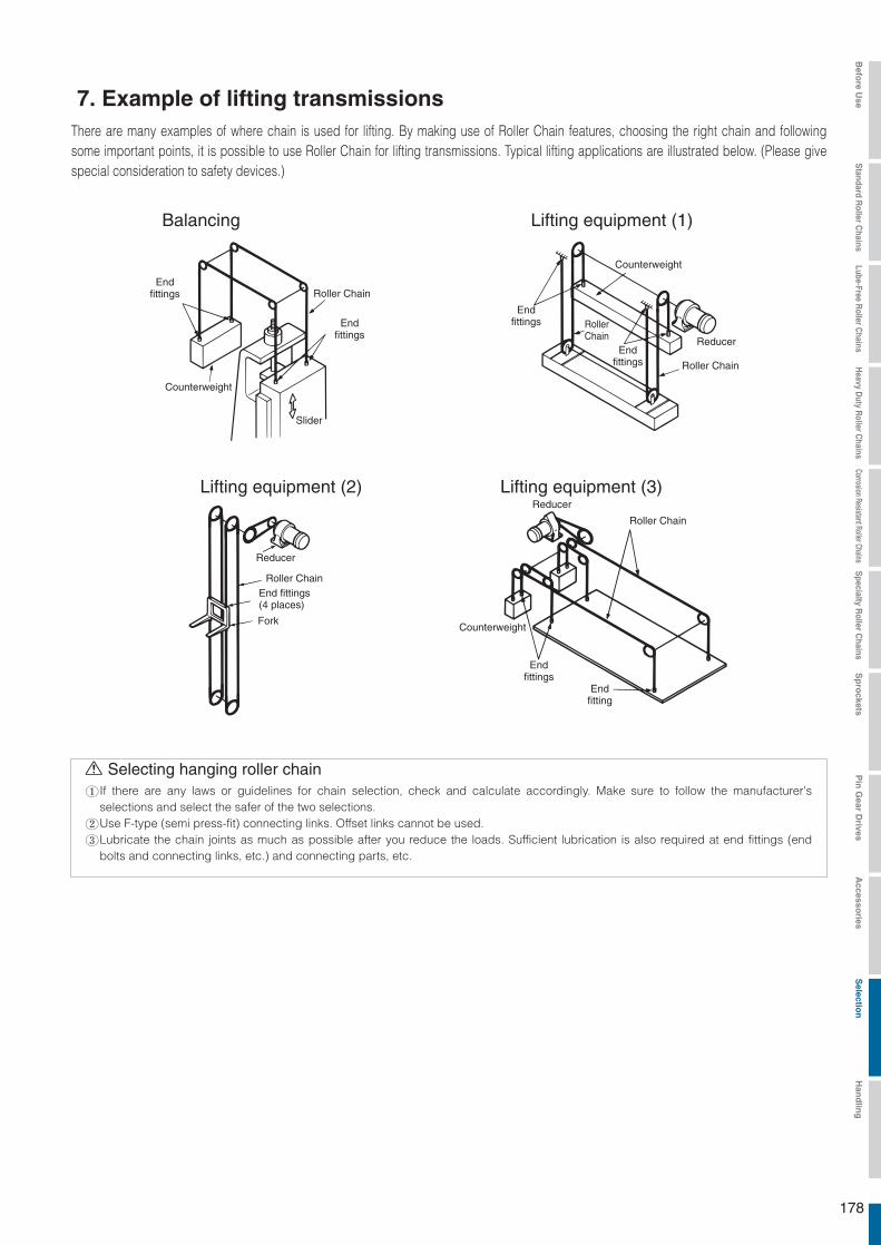
There are many examples of where chain is used for lifting. By making use of Roller Chain features, choosing the right chain and following some important points, it is possible to use Roller Chain for lifting transmissions. Typical lifting applications are illustrated below. (Please give special consideration to safety devices.)
7. Example of lifting transmissions
Balancing
Endfittings
Endfittings
Endfittings
Endfittings
Endfitting
Endfittings
Counterweight
Counterweight
Counterweight
Slider
Roller Chain
Roller Chain
Roller Chain
Roller Chain
RollerChain
Lifting equipment (1)
Lifting equipment (2)
Reducer
Reducer
Reducer
End fittings(4 places)
Fork
Lifting equipment (3)
Selecting hanging roller chainIf there are any laws or guidelines for chain selection, check and calculate accordingly. Make sure to follow the manufacturer's selections and select the safer of the two selections.Use F-type (semi press-fit) connecting links. Offset links cannot be used.Lubricate the chain joints as much as possible after you reduce the loads. Sufficient lubrication is also required at end fittings (end bolts and connecting links, etc.) and connecting parts, etc.
178
Befo
re Use
Standard R
oller Chains
Lube-Free Roller C
hainsH
eavy Duty R
oller Chains
Corrosion Resistant Roller ChainsS
pecialty Roller C
hainsS
pro
cketsP
in G
ear Drives
Accesso
riesS
election
Han
dlin
g
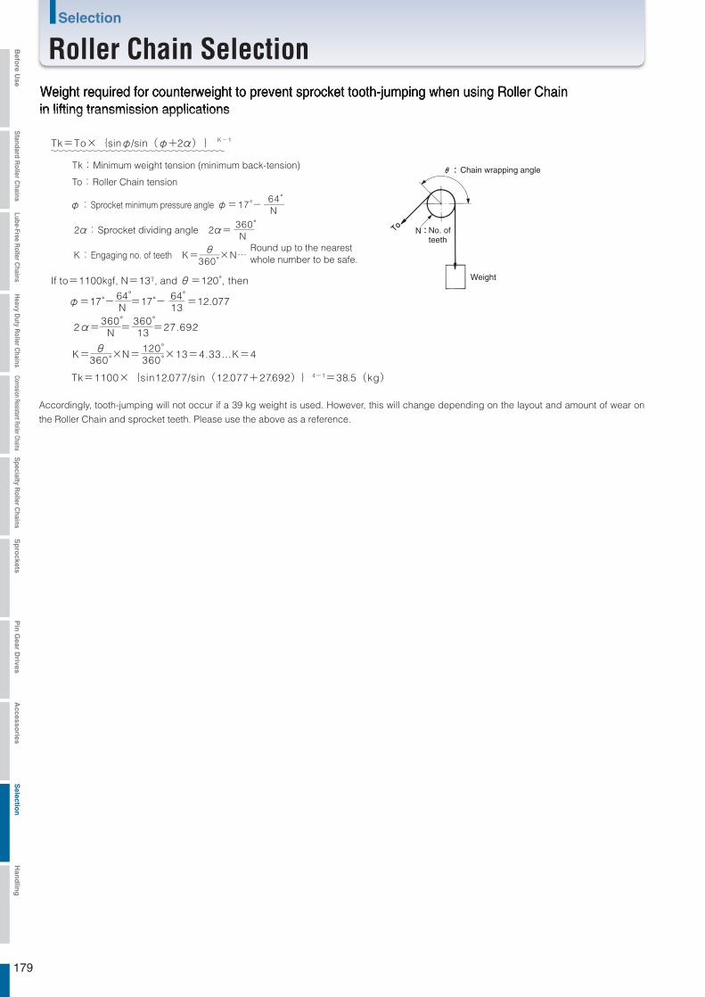
Tk:Minimum weight tension (minimum back-tension)
To:Roller Chain tension
φ:Sprocket minimum pressure angle
2α:Sprocket dividing angle 2α=
K:Engaging no. of teeth K= ×N…
φ=17°-64° N
360° N
θ360°
θ 360°
Tk=To×{sinφ/sin(φ+2α) } K-1
If to=1100kgf, N=13T, and θ=120°, then
φ=17°- =17°- =12.07764° N
64°13
2α= = =27.692360° N
120°360°
360° 13
K= ×N= ×13=4.33…K=4
Tk=1100×{sin12.077/sin(12.077+27.692)}4-1=38.5(kg)
Accordingly, tooth-jumping will not occur if a 39 kg weight is used. However, this will change depending on the layout and amount of wear on
the Roller Chain and sprocket teeth. Please use the above as a reference.
N
Weight required for counterweight to prevent sprocket tooth-jumping when using Roller Chainin lifting transmission applications
Round up to the nearestwhole number to be safe.
Weight
No. ofteeth
Chain wrapping angle
179
Selection
Roller Chain SelectionBefo
re Use
Standard R
oller Chains
Lube-Free Roller C
hainsH
eavy Duty R
oller Chains
Corrosion Resistant Roller ChainsS
pecialty Roller C
hainsS
pro
cketsP
in G
ear Drives
Accesso
riesS
election
Han
dlin
g

M(kg)W(kgf)
r= D2 (m)
D(m)
D2(m)
D1(m)
M(kg)W(kgf)
r1=D12 (m) r2=D22 (m)
M(kg)W(kgf)Work
Sprocket Conveyor Chain
r= D2 (m)
M(kg)W(kgf)Shuttle
Sprocket withpin gear
Roller Chain with attachment
r= D2 (m)
M(kg)W(kgf)
Sprocket
Roller Chain
r= D2 (m)
D(m)
M(kg)W(kgf)Shuttle
Sprocket Roller Chain
M(kg)W(kgf)
D(m)Shuttle
Sprocket
Roller Chain
r= D2 (m)
Roller Chain
Sprocket
Pin gear Roller Chain
Pin gear sprocket
I=1Mr22
(kg・m2)
GD2=1WD22
(kgf・m2)I=Mr2 (kg・m2)
GD2=WD2
(kgf・m2)
I=Mr2 (kg・m2)GD2=WD2
(kgf・m2)
I=Mr2 (kg・m2)GD2=WD2
(kgf・m2)
I=Mr2 (kg・m2)GD2=WD2
(kgf・m2)
I = ( n2 )2
I
I =M ( V )2
n1
=I(kg・m2)i2
2πn1(kg・m2)
GD2 =( n2)2
GD2n1
=GD2 (kgf・m2)i2
GD2 =W( V )2
πn1(kgf・m2)
I=1M(r12+r22)2(kg・m2)
GD2=1W(D12+D22)2(kgf・m2)
1 kg・m2
(I)4 kgf・m2
(GD2)
8. Calculating moment of inertia (Table 6)
Rotating Body (Moment of inertia)Calculation Method (SI Unit)
GD2 CalculationMethod (Gravimetric Unit)
(Moment of inertia)Calculation Method (SI Unit)
GD2 CalculationMethod (Gravimetric Unit)
Right cylinder
Hollow right cylinder
Wrapping drive Pin gear drive
Linear Body
Conveyor drive
Shuttle Traction
Pin gear drive
Lifting application
To convert moment of inertia load tomotor shaft n1: Motor shaft rotating speed n2: Load shaft rotating speed
Moment of inertia load
Moment of inertia GD2 load
The above does not include the mass of the sprocket and chain.
Note
SI unit {Gravimetric unit}
Moment of inertia (I)and fly wheel effect (GD2)
180
Befo
re Use
Standard R
oller Chains
Lube-Free Roller C
hainsH
eavy Duty R
oller Chains
Corrosion Resistant Roller ChainsS
pecialty Roller C
hainsS
pro
cketsP
in G
ear Drives
Accesso
riesS
election
Han
dlin
g
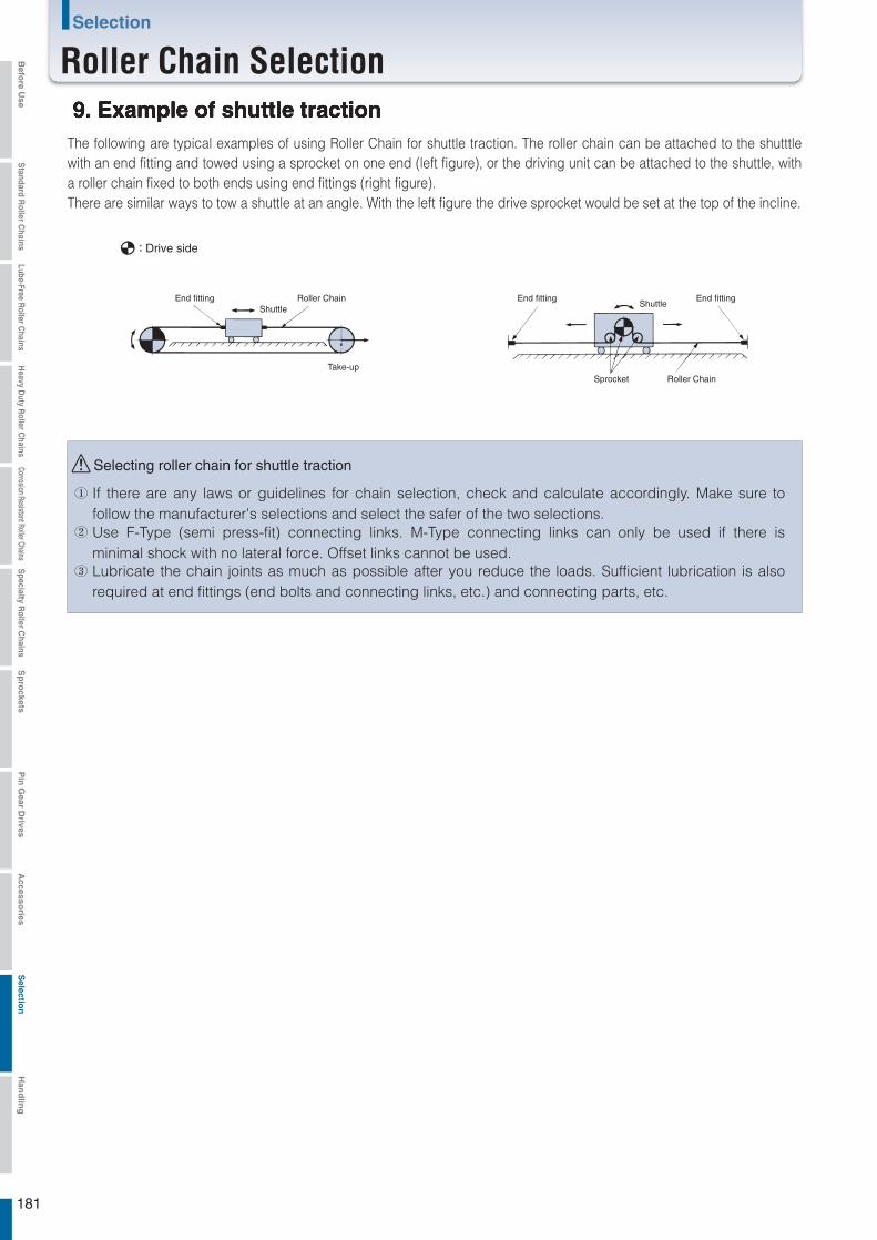
①
②
③ Lubricate the chain joints as much as possible after you reduce the loads. Sufficient lubrication is also required at end fittings (end bolts and connecting links, etc.) and connecting parts, etc.
Use F-Type (semi press-fit) connecting links. M-Type connecting links can only be used if there is minimal shock with no lateral force. Offset links cannot be used.
If there are any laws or guidelines for chain selection, check and calculate accordingly. Make sure to follow the manufacturer's selections and select the safer of the two selections.
9. Example of shuttle tractionThe following are typical examples of using Roller Chain for shuttle traction. The roller chain can be attached to the shutttle with an end fitting and towed using a sprocket on one end (left figure), or the driving unit can be attached to the shuttle, with a roller chain fixed to both ends using end fittings (right figure).There are similar ways to tow a shuttle at an angle. With the left figure the drive sprocket would be set at the top of the incline.
Drive side
End fitting End fitting End fittingShuttle
ShuttleRoller Chain
Take-upSprocket Roller Chain
Selecting roller chain for shuttle traction
181
Selection
Roller Chain SelectionBefo
re Use
Standard R
oller Chains
Lube-Free Roller C
hainsH
eavy Duty R
oller Chains
Corrosion Resistant Roller ChainsS
pecialty Roller C
hainsS
pro
cketsP
in G
ear Drives
Accesso
riesS
election
Han
dlin
g

Pinion gear
Wheel
Pin gear sprocket
Attachment chain
Attachment chain
Pin gear sprocket
●Use standard roller chain.
●Used an attachment roller chain.
K1 attachment every 2nd link
SK1 attachment every 2nd link
10. Pin gear drive selection methodGenerally, linear movement or large radius rotation is made possible by a roller chain and gear through a transmission source (motor, etc.) via a reducer.A roller chain, however, needs a lot of space, and gears require precision machining, which increases the cost. A pin gear is ideal in these situations.
Roller chain Gear Pin gear (Linear) Pin gear (Rotary)
For pin gear drives, a roller chain is wrapped around the perimeter of a drum to make a wheel, and special sprockets (see Sprockets) are used instead of pinion gears. For linear motion, a roller chain is attached and used linearly instead of a rack.
Item Pin gear drive Roller chain transmission Gear transmissionRestrictions on distancebetween shafts Yes YesNo
Number of engaged teeth Low LowHigh
Speed ratio range No limit No limitUp to 1:7
Tooth shape Special teeth Sprocket teeth Involute
Engagement accuracy NormalNormal Precise
Economical at large speed ratios (1:5 or larger), especially when the drum has a large diameter.Roller chain attachments are bolted onto the drum for easy installation and maintenance.Design freedom in drum diameter, linear length, etc.Rough installation accuracy and no precision machining required for gears.Grease lubrication can be used.A pin gear is not suitable for ultra precise drives, and the noise level is high compared to gears.
1)
2)3)4)5)
10.2 Chain installation and precautions
10.1 Characteristics of pin gears
1) When used linearly (rack) with rollers facing up:
Connecting links are used on both ends, and fittings are attached and bolts and nuts are fastened to remove any slack. (Both ends need to be secured snugly with double nuts.) NOTE: This is not recommended as tooth slipping and interference can occur.
Attach K1 or SK1 attachments every 2nd link and fasten with bolts and nuts every 2nd or 4th link with chain pulled taut so there is no slack or meandering. (K attachments are recommended.) The attachment holes are usually processed on-site.
182
Befo
re Use
Standard R
oller Chains
Lube-Free Roller C
hainsH
eavy Duty R
oller Chains
Corrosion Resistant Roller ChainsS
pecialty Roller C
hainsS
pro
cketsP
in G
ear Drives
Accesso
riesS
election
Han
dlin
g

The length of the chain should be the travel distance plus α.
α : The distance of overrun based on usage conditions.
Contact a Tsubaki representative.
See section 3).
Contact a Tsubaki representative for internal fits.
K1 attachment every 2nd link
SK1 attachment every 2nd link
Roller
Dial gauge
α
1.0mm
1.5mm
2.0mm
Use bolts with a strength class 8.8 or higher (JIS1051-2000 Tensile strength 800 N/mm2 or higher). (SCM435 heat treated bolts, etc.)
Attach K1 or SK1 attachments every 2nd link and fasten with bolts and nuts every 2nd or 4th link with chain pulled taut so there is no slack or meandering.
Adjust the shaft of the sprocket so that the sprocket engages the chain straight.
The clearance (α) between the rollers and the bottom of the sprocket teeth should be less than the dimensions shown
in the following table. The bottom of the teeth and rollers should not touch each other.
When the bottom of the teeth and rollers touch each other in the clearance described above, the tooth form needs to be
pre-designed with larger clearance α. Contact a Tsubaki representative for details.
2) When used linearly (rack) with rollers facing down:
3) When wrapped partially or totally around the outside of a drum:Attachment chain length is in the range of -0.05 to 0.15% of standard length
(nominal pitch x number of links). When the chain is wrapped around a drum,
shims need to be used between the drum and the chain attachments to
eliminate slack.
Since K attachments can be adjusted with shims, they can be attached onto
the drum more easily than SK attachments.
When the drum is not perfectly round, the thickness of the shims needs to be
adjusted while the chain is wrapped around the drum so the radius is circular.
As shown below, a dial gauge or a surface gauge can be used for adjustment.
Process tap holes to fit the holes of the chain attachments.
4) When wrapped partially or totally around the inside of a drum:
5) When used for lateral wrapping (horizontal drive)
6) Sprocket attachment
Chain size
RS80 or less
RS100 to RS180
RS200 or more
183
Selection
Roller Chain SelectionBefo
re Use
Standard R
oller Chains
Lube-Free Roller C
hainsH
eavy Duty R
oller Chains
Corrosion Resistant Roller ChainsS
pecialty Roller C
hainsS
pro
cketsP
in G
ear Drives
Accesso
riesS
election
Han
dlin
g
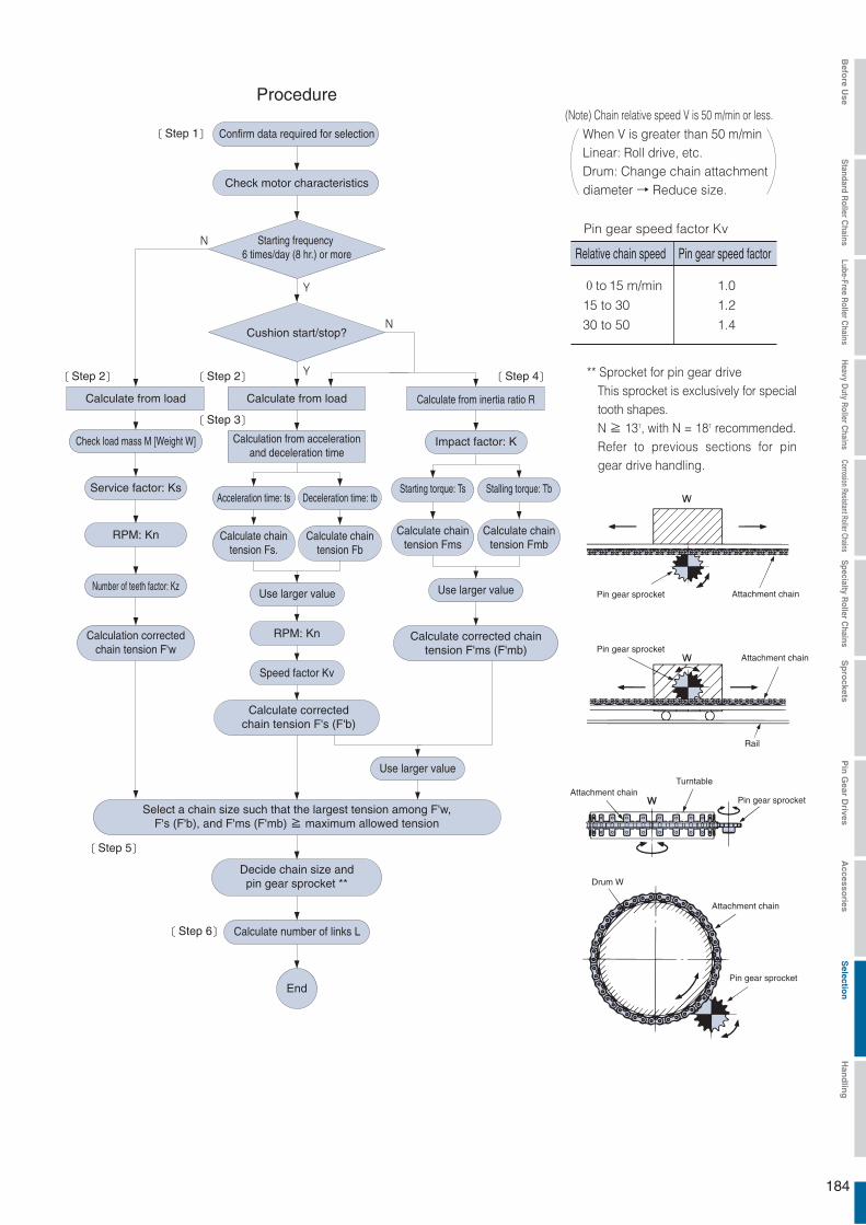
(Note) Chain relative speed V is 50 m/min or less.
Pin gear speed factor Kv
0to 15 m/min
15 to 30
30 to 50
1.0
1.2
1.4
Procedure
Confirm data required for selection
Check motor characteristics
Starting frequency 6 times/day (8 hr.) or more
Cushion start/stop?
Calculate from load Calculate from load
Check load mass M [Weight W]
Service factor: Ks
RPM: Kn
Speed factor Kv
Calculation correctedchain tension F'w
Acceleration time: ts Deceleration time: tb
Calculate chaintension Fs.
Calculate chaintension Fb
Use larger value Use larger value
Use larger value
Calculate correctedchain tension F's (F'b)
Calculate from inertia ratio R
Impact factor: K
Starting torque: Ts Stalling torque: Tb
Calculate chaintension Fms
Calculate chaintension Fmb
Calculate corrected chaintension F'ms (F'mb)
Select a chain size such that the largest tension among F'w,F's (F'b), and F'ms (F'mb) ≧ maximum allowed tension
Decide chain size andpin gear sprocket **
Calculate number of links L
End
Step 1
Step 2 Step 2 Step 4
Step 3
Calculation from accelerationand deceleration time
Step 5
Step 6
When V is greater than 50 m/minLinear: Roll drive, etc.Drum: Change chain attachmentdiameter → Reduce size.
Relative chain speed Pin gear speed factor
** Sprocket for pin gear driveThis sprocket is exclusively for special tooth shapes.N ≧ 13T, with N = 18T recommended.Refer to previous sections for pin gear drive handling.
Pin gear sprocket
Pin gear sprocket
Pin gear sprocket
Pin gear sprocket
Attachment chain
Attachment chain
Attachment chain
Attachment chain
Rail
Turntable
Drum W
RPM: Kn
Number of teeth factor: Kz
184
Befo
re Use
Standard R
oller Chains
Lube-Free Roller C
hainsH
eavy Duty R
oller Chains
Corrosion Resistant Roller ChainsS
pecialty Roller C
hainsS
pro
cketsP
in G
ear Drives
Accesso
riesS
election
Han
dlin
g

V =
n=1750 × = 9.6 rpm1
181 .9
220×π× 9 .61000
=6 .6 m / m i n… K v= 1 .0
Rated torque of the motor T n=9.55×
T =T n× i=0.00819×181.9
=1.49(k N・m)
=9.55×
=0.00819(k N・m)
K s= 1 .5
k Wk Wn1
1.51750
Chain working tension
Design chain tension
F= =
F′w=F×K s×K v
=13.6(k N)
2Td
2×1.490.22
=13.6×1.5×1.0
=20.4(k N)
Pin gear drive sprocket shaft torque
・・・・・・・・・・・・・・・・・・
Rated torque of the motor T n=974×
T =T n× i=0.835×181.9
=974×
=0.835(kgf・m)
=152(kgf・m)
k Wn1
1.51750
Chain working tension
Design chain tension
F= =
F′w=F×K s×K v
=1382(kgf)
2Td
2×1.490.22
=1382×1.5×1.0
=2073(kgf)
Pin gear drive sprocket shaft torque
・・・・・・・・・・・・・・・・・・11
Attachment chain
2920
Motor
Pin gear specialized sprocket
Support roller
Reducer reduction ratioi = 181.9
GD2=0.017kgf・m2
Pin gear drive selection example
SI units
[Step 1] Check machine and motor characteristics [Step 1] Check machine and motor characteristics
Machine: Cutting machine
Motor: 15 kW, 4P, 1750 rpmMachine: Cutting machine
Motor: 15 kW, 4P, 1750 rpm
Motor moment of inertia I: Im = 0.00425 kg・m2
Starting torque Ts ・・・・・・・・・・・・・・・・・・・・・・・・・・・・・・ 290%
Stalling torque Tb ・・・・・・・・・・・・・・・・・・・・・・・・・・・・・・ 305%
Reducer reduction ratio i ・・・・・・・・・・・・・・・・・・・・・・・・・・ 181.9
Forward and reverse operation frequency ・・・ Max 900 times/hour
Sprocket pitch circle diameter (PCD) ・・・ Approximately φ220 mm
Starting torque Ts ・・・・・・・・・・・・・・・・・・・・・・・・・・・・・・ 290%
Stalling torque Tb ・・・・・・・・・・・・・・・・・・・・・・・・・・・・・・ 305%
Reducer reduction ratio i ・・・・・・・・・・・・・・・・・・・・・・・・・・ 181.9
Forward and reverse operation frequency ・・・ Max 900 times/hour
Sprocket pitch circle diameter (PCD) ・・・ Approximately φ220 mm
Moment of inertia for the motor shaft converted load I: I = 0.00072 kg・m2
There is no play in the chain.
GD2 of the motor shaft converted load: GD
2 = 0.00072 kg・m2
There is no play in the chain.
[Step 2] Calculation from load [Step 2] Calculation from load
Revolution speed of the pin gear drive sprocket
Relative chain speed Speed factor
High forward and reverse operation frequency ・・・・・・・・・・・・・ Service factor
Load is calculated from the torque on the drive side as the mass of the load is unknown.
{Gravimetric units}
GD2 of the motor
185
Selection
Roller Chain SelectionBefo
re Use
Standard R
oller Chains
Lube-Free Roller C
hainsH
eavy Duty R
oller Chains
Corrosion Resistant Roller ChainsS
pecialty Roller C
hainsS
pro
cketsP
in G
ear Drives
Accesso
riesS
election
Han
dlin
g
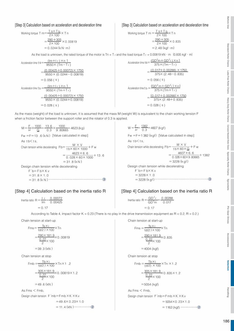
Working torque T m=T s+T b×T n2×100
2×100=290+305
×0 .00819
=0.0244 (k N・m)
M=F×
1000=
13.6×
1000=4623 (kg)μ G 0.3 9 .80665
Fw=F=13 .6 (k N )
W=F=
1382=4607 (kgf)μ 0.3
Fw=F=1 382 (kgf)
t b= (Im+I ) ×n1
t s= (Im+I ) ×n1
9550× (Tm-T
9550× (Tm+T
=(0.00425+0.00072)×1750
=(0 .00425+0.00072)×1750
9550× (0 .0244-0.00819)
9550× (0 .0244+0.00819)
=0.056 ( s )
=0.028 ( s )
Working torque T m=T s+T b×T n2×100
2×100=
290+305×0 .835
=2.48 (kgf・m)
t b=(GD2 m+GD2 ) ×n1
ts= (GD2m+GD2 ) ×n1375×(Tm-T )
375×(Tm+T )
=(0.017+0.00288)×1750
=(0 .017+0.00288)×1750
375× (2 .48-0.835)
375× (2 .48+0.835)
=0.056 ( s )
=0.028 ( s )
Inertia ratio R=I=
0.00072Im .00425
= 0.17
Chain tension at start-up
Fms= Ts×i
×Tn(d/2 )×100
=290×181.9
×0 .008190.22×100
2
=39.3 (kN )
Chain tension at stop
Design chain tension F mb=F mb×K×Kv
Fmb= Tb×i
×Tn×1 .2(d/2 )×100
=305×181.9
×0 .00819×1.20.22×100
2
=49.6 (kN )
As Fms < Fmb, As Fms < Fmb,
=49.6×0.23×1.0
=11 .4 (kN ) ・・・・・・・・・・・・・・・・2
Chain tension at start-up
Fms= Ts×i
×Tn(d/2 )×100
=290×181.9
×0 .8350.22×100
2
=4004 (kgf)
Chain tension at stop
Design chain tension F mb=F mb×K×Kv
Fmb= Tb×i
×Tn×1 .2(d/2) ×100
=305×181.9
×0 .835×1.20.22×100
2
=5054 (kgf)
=5054×0 .23×1.0
=1162 (kgf)・・・・・・・・・・・・・・・・2
Inertia ratio R=GD 2
=0.00288
= 0.17
GD2m 0.017
t b< t s,
Chain tension while decelerating Fb=M × V
+F wt b×60×1000
=4623×6. 6
+13 . 60 . 028×60×1000
=31 .8 (k N )
Design chain tension while deceleratingF b=F b×K v=31 .8×1 . 0=31 .8 (k N )・・・・・・・・・・・・・・・・・・・・・・・・・・・・・・・・・・・・・・・・・・・・・3
Chain tension while decelerating Fb=W× V
+F wt b×60×G
=4607×6. 6
+13820.028×60×9 .80665
=3228 (k gf )
Design chain tension while deceleratingF b=F b×K v=3228×1 . 0=3228 (k gf )・・・・・・・・・・・・・・・・・・・・・・・・・・・・・・・・・・・・・・・・・・・・・3
[Step 3] Calculation based on acceleration and deceleration time [Step 3] Calculation based on acceleration and deceleration time
As the load is unknown, the rated torque of the motor is Tn = T and the load torque T = 0.00819 kN・m{0.835 kgf・m}
Acceleration time
Acceleration time Acceleration time
As the mass (weight) of the load is unknown, it is assumed that the mass M (weight W) is equivalent to the chain working tension Fwhen a friction factor between the support roller and the rotator of 0.3 is applied.
[Value calculated in step] [Value calculated in step]
As t b< t s,As
[Step 4] Calculation based on the inertia ratio R [Step 4] Calculation based on the inertia ratio R
According to Table 4, impact factor K = 0.23 (There is no play in the drive transmission equipment as R < 0.2, R = 0.2.)
Acceleration time)
)
0
186
Befo
re Use
Standard R
oller Chains
Lube-Free Roller C
hainsH
eavy Duty R
oller Chains
Corrosion Resistant Roller ChainsS
pecialty Roller C
hainsS
pro
cketsP
in G
ear Drives
Accesso
riesS
election
Han
dlin
g

Comparing , , and , an attachment chain for pin gears that meets 31.8kN [3228 kgf], the maximum working load is selected.
The maximum allowable load for RS160 attachment chain, 37.3 kN [3800 kgf], is acceptable.
The number of the teeth is N = 14 T from the pitch circle diameter of the pin gear specialized sprocket, approximately φ220. (PCD = 231.78 mm)
F =2 T=
2×1.49= 12.9 (k N )
d 0.23178
F w=F×K v
= 12 .9×1 . 0=12 .9 (k N )
F m b=T b× i
×T n×1.2(d/ 2)×100
=305×181.9
×0. 00819×1.2= 46.4 (k N )0.23178×100
2
F mb=F m b×K ×K v
=46 .4×0 .23×1 . 0=10 . 7 (k N )
The above selection is acceptable.
F =2 T=
2×152=1295 (k gf )
d 0.23178
F w=F×K v
= 1295×1 . 0=1295 (k gf )
F m b=T b× i
×T n×1.2(d/ 2)×100
=305×181.9
×0. 835×1 .2=4797 (k gf )0.23178×100
2
F mb=F m b×K ×K v
=4797×0 .23×1 . 0=1103 (k gf )
The above selection is acceptable.
= 180゜ = 180゜ =180.6・・・・・・182 linkstan-1 ( P ) tan-1 ( 50 . 8 )D+2S 2920
21 3 3
[Step 5] Comparison of , , and
Step 2 and 3 are calculated again here.
[Step 2] [Step 2]
[Step 3] [Step 3]
[Step 6] Calculation of the number of links L
Number of links L
[Conclusion] Chain: RS160 K1 attachments on every 2nd link with 182 links Sprocket: RS160 pin gear specialized sprocket 14T
(PCD231.78 mm) or larger, S35C steel, teeth induction hardened.
Ambient conditions during applications are not taken into consideration. When the ambient conditions are not adequate, the
selection needs to be made in consideration of the conditions.
Refer to Section 10.2 on page 182 for cautions regarding pin gears.
(Cautions)
187
Selection
Roller Chain SelectionBefo
re Use
Standard R
oller Chains
Lube-Free Roller C
hainsH
eavy Duty R
oller Chains
Corrosion Resistant Roller ChainsS
pecialty Roller C
hainsS
pro
cketsP
in G
ear Drives
Accesso
riesS
election
Han
dlin
g
1
2

When selecting Corrosion Resistant Chain use the allowable load selection method.
× × × ≦
- -
- 60℃ - - -
- 50℃ - -
- 40℃ -
- 30℃ - 〃 ×1/3
〃 ×2/3
〃
- 20℃ - 〃 ×1/3 〃 ×1/2 〃
- 10℃ - 〃
60℃ -
150℃ - 〃 ×3/4 〃 ×3/4 -
200℃ - 〃 ×1/2 〃 ×1/2 -
-
- 50℃
- 40℃
- 30℃
- 20℃
- 10℃
60℃
150℃
200℃
250℃
11. Temperature Selection Method11.1 RS Roller Chain temperature selection methodThis selection method is for sizes that may experience strength degradation from temperature.Additionally, lubrication shoud be carried out using a suitable lubricant according to the operating temperatures.1) Problems with roller chain transmission at high temperatures
Increased wear due to hardness reductionIncreased elongation due to softeningPoor articulation and increased wear due to oil degradation and carburizationIncreased wear and poor articulation due to scaling
2) Problems with roller chain transmission at low temperaturesReduction of impact strength due to low temperature brittlenessSolidification of lubricantPoor articutation due to frost and ice adhesion
Table 7 Maximum allowable load of RS Roller Chain at high and low temperatures
TemperatureRS roller chain
RS60 or under RS80 or overRS Cold Resistant Chain *
Below-60℃ Unusable
Unusable
Unusable
Unusable
Catalog Value × 1/2
Catalog Value
Catalog Value
Catalog Value
Catalog Value
Catalog Value
Catalog Value × 1/4
Catalog Value × 1/4
Over 250℃
Note)1. * RS Cold Resistant Chain Made to order Select using allowable load selection method2. The ambient temperature is different from the temperature of the roller chain itself.
Unusable
Unusable
11.3 Selection method for Stainless Steel Roller Chain (SS and NS series) at high temperatures (400℃ or higher)As the temperature of a chain increases, its strength decreases. The usage limit at high temperatures is determined by the temperature of the chain itself. Contact a Tsubaki representative when using stainless steel chain at ambient temperatures of 400℃ or higher. However, chain cannot be used at 700℃ or higher. When a chain is selected using the temperature selection method, the chain speed must be below the maximum speed of the allowable load selection method.Changes and cautions associated with high temperature environments are: 1) All clearances need to be abjusted to prevent poor articulation and poor roller rotation due to thermal expansion. 2) The chain may break (creep rupture) under low loads as the temperature increases.
1) The maximum allowable tension for Corrosion Resistant Chain is low compared to Standard RS Roller Chain (excluding NEP).2) Avoid using offset links when possible.3) Refer to the following page when acid or alkali solutions or chemicals will come in direct contact with the chain.4) Selection formula:
12. Special selection method for Corrosion Resistant Roller Chain
Maximum allowableload of the chain
Number of teethfactor
KzRPMKn
Servicefactor
KsMaximum working load applied to the chain
Use the kilowatt ratings chart based selection method for selecting lube free drive chains.
11.2 Lambda Chain KF Series Lube Free Drive Chain Selection
Corrected kW < kW ratings = Catalog kW ratings × Temperature coefficient
Note: The chain is usable if the kilowatt ratings are greater than the corrected kW.
Multiply the ambient temperature the chain will be used in by the temperature coefficient in Table 2 below to calculate kilowatt ratings.Calculate the temperature coefficient with the maximum usage temperature of the equipment on which the chain will be installed.Table 2: Temperature Coefficient by Ambient Temperature
Temperature RS40 – RS80
Room temperature – 150°C Catalog kW rating × 1
150°C – 200°C Catalog kW rating × 3/4
200°C – 230°C Catalog kW rating × 1/2
Note: A double-strand LMC chain only has the maximum allowable load of a single-strand LMD chain.Always confirm strength when using for power transmission.
188
Befo
re Use
Standard R
oller Chains
Lube-Free Roller C
hainsH
eavy Duty R
oller Chains
Corrosion Resistant Roller ChainsS
pecialty Roller C
hainsS
pro
cketsP
in G
ear Drives
Accesso
riesS
election
Han
dlin
g
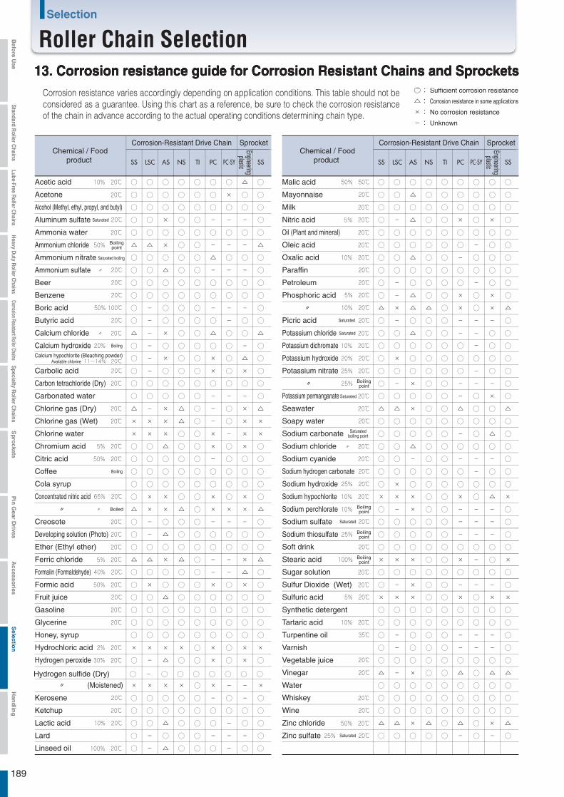
○:
△:
×:
-:
13. Corrosion resistance guide for Corrosion Resistant Chains and SprocketsCorrosion resistance varies accordingly depending on application conditions. This table should not be considered as a guarantee. Using this chart as a reference, be sure to check the corrosion resistance of the chain in advance according to the actual operating conditions determining chain type.
Sufficient corrosion resistance
No corrosion resistance
Unknown
Corrosion resistance in some applications
Chemical / Foodproduct
Corrosion-Resistant Drive Chain Sprocket
Engineeringplastic
Chemical / Foodproduct
Corrosion-Resistant Drive Chain Sprocket
Engineeringplastic
Acetone ◯ ◯ ◯ ◯ ◯ × ◯ ◯◯
Calcium hypochlorite (Bleaching powder)Available chlorine ◯ × ◯ ◯ × ◯ △ ◯-
Potassium nitrate ◯ ◯ ◯ ◯ ◯ - ◯ ◯◯
Boilingpoint ◯ × ◯ ◯ - - - ◯-
Boiled △ × △ ◯ × × × △×
△ △ △ ◯ × ◯ × △×
189
◯ ◯ ◯ ◯ ◯ ◯ ◯ ◯◯Oil (Plant and mineral)
◯ △ ◯ ◯ ◯ - ◯ ◯-Linseed oil
◯ × ◯ ◯ - - - ◯-Sulfur Dioxide (Wet)
◯ ◯ ◯ ◯ ◯ ◯ ◯ ◯◯Alcohol (Methyl, ethyl, propyl, and butyl)
◯ ◯ ◯ ◯ ◯ ◯ ◯ ◯◯Ammonia water
◯ ◯ ◯ ◯ ◯ ◯ ◯ ◯◯Whiskey
◯ ◯ ◯ ◯ ◯ ◯ ◯ ◯◯Ether (Ethyl ether)
△ × △ ◯ △ ◯ × △△Zinc chloride
Boilingpoint △ × ◯ ◯ - - - △△Ammonium chloride
Saturated ◯ △ ◯ ◯ - - ◯ ◯◯Potassium chloride△ × ◯ ◯ △ ◯ ◯ △-Calcium chloride
△ × △ ◯ - - × △△Ferric chloride
◯ △ ◯ ◯ ◯ ◯ ◯ ◯◯Sodium chloride
× × × ◯ × ◯ × ××Hydrochloric acid
△ × △ ◯ - ◯ × △-Chlorine gas (Dry)
× × △ ◯ - ◯ × ××Chlorine gas (Wet)
× × ◯ ◯ × - × ××Chlorine water
◯ ◯ ◯ ◯ ◯ - ◯ ◯◯Oleic acid
△ × ◯ ◯ △ ◯ ◯ △△Seawater
Boilingpoint ◯ × ◯ ◯ - - - ◯-Sodium perchlorate
◯ △ ◯ ◯ × ◯ × ◯-Hydrogen peroxide
◯ ◯ ◯ ◯ ◯ ◯ ◯ ◯◯Gasoline
Saturated ◯ ◯ ◯ ◯ - ◯ × ◯◯Potassium permanganate
◯ ◯ ◯ ◯ × ◯ × ◯×Formic acid
◯ ◯ ◯ ◯ ◯ ◯ ◯ ◯◯Milk
◯ ◯ ◯ ◯ - ◯ ◯ ◯◯Citric acid
◯ ◯ ◯ ◯ ◯ ◯ ◯ ◯◯Glycerine
◯ ◯ ◯ ◯ - - - ◯-Creosote
◯ △ ◯ ◯ × ◯ × ◯◯Chromium acid
◯ ◯ ◯ ◯ ◯ ◯ ◯ ◯◯Ketchup
◯ △ ◯ ◯ ◯ ◯ ◯ ◯-Developing solution (Photo)
◯ ◯ ◯ ◯ ◯ ◯ ◯ ◯◯Synthetic detergent
Boiling ◯ ◯ ◯ ◯ ◯ ◯ ◯ ◯◯Coffee
◯ ◯ ◯ ◯ ◯ ◯ ◯ ◯◯Cola syrup
◯ ◯ ◯ ◯ ◯ ◯ △ ◯◯Acetic acid
◯ ◯ ◯ ◯ ◯ ◯ ◯ ◯◯Sugar solution
× × ◯ ◯ × ◯ △ ××Sodium hypochlorite
◯ - ◯ ◯ - - - ◯◯Sodium cyanide
◯ ◯ ◯ ◯ ◯ ◯ ◯ ◯◯Carbon tetrachloride (Dry)
◯ ◯ ◯ ◯ ◯ - ◯ ◯◯Potassium dichromate
◯ △ ◯ ◯ - ◯ ◯ ◯◯Oxalic acid
◯ ◯ ◯ ◯ ◯ ◯ ◯ ◯◯Tartaric acid
◯ △ ◯ ◯ × ◯ × ◯-Nitric acid
Saturated boiling ◯ ◯ ◯ ◯ △ ◯ ◯ ◯◯Ammonium nitrate
△ × ◯ ◯ △ ◯ △ △-Vinegar
◯ ◯ ◯ ◯ ◯ ◯ ◯ ◯×Potassium hydroxide
Boiling ◯ ◯ ◯ ◯ ◯ ◯ - ◯-Calcium hydroxide
◯ ◯ ◯ ◯ ◯ ◯ ◯ ◯×Sodium hydroxide
Boilingpoint × × ◯ ◯ × - ◯ ××Stearic acid
◯ ◯ ◯ ◯ ◯ ◯ ◯ ◯◯Soft drink
◯ ◯ ◯ ◯ × ◯ × ◯-Carbolic acid
◯ ◯ ◯ ◯ ◯ - ◯ ◯-Petroleum
◯ ◯ ◯ ◯ ◯ ◯ ◯ ◯◯Soapy water
◯ ◯ ◯ ◯ - - - ◯◯Carbonated water
◯ ◯ ◯ ◯ ◯ - ◯ ◯◯Sodium hydrogen carbonate
Saturatedboiling point ◯ ◯ ◯ ◯ - ◯ △ ◯◯Sodium carbonate
Boilingpoint ◯ ◯ ◯ ◯ - - - ◯◯Sodium thiosulfate
◯ ◯ ◯ ◯ - - - ◯-Turpentine oil
◯ ◯ ◯ ◯ - ◯ - ◯◯Kerosene
◯ ◯ ◯ ◯ - - - ◯-Varnish
◯ × ◯ ◯ × ◯ × ◯×Concentrated nitric acid
◯ △ ◯ ◯ ◯ - ◯ ◯◯Lactic acid
◯ ◯ ◯ ◯ ◯ ◯ ◯ ◯◯Honey, syrup
◯ ◯ ◯ ◯ ◯ ◯ ◯ ◯◯Paraffin
◯ ◯ ◯ ◯ ◯ ◯ ◯ ◯◯Beer
Saturated ◯ ◯ ◯ ◯ - - - ◯-Picric acid
◯ △ ◯ ◯ ◯ ◯ ◯ ◯◯Fruit juice
◯ ◯ ◯ ◯ ◯ ◯ ◯ ◯◯Benzene
◯ ◯ ◯ ◯ - - - ◯-Boric acid
◯ ◯ ◯ ◯ - - △ ◯◯Formalin (Formaldehyde)
◯ △ ◯ ◯ ◯ ◯ ◯ ◯◯Mayonnaise
◯ ◯ ◯ ◯ ◯ ◯ ◯ ◯◯Water
◯ ◯ ◯ ◯ ◯ ◯ ◯ ◯◯Vegetable juice
◯ ◯ ◯ ◯ - - - ◯-Lard
◯ ◯ ◯ ◯ ◯ - ◯ ◯-Butyric acid
◯ ◯ ◯ ◯ ◯ ◯ ◯ ◯-Hydrogen sulfide (Dry)
× × × ◯ × - - ×× (Moistened)
× × ◯ ◯ × ◯ × ××Sulfuric acid
Saturated ◯ ◯ ◯ ◯ - ◯ - ◯◯Zinc sulfate
Saturated ◯ × ◯ ◯ - - - ◯◯Aluminum sulfate
◯ △ ◯ ◯ - - - ◯◯Ammonium sulfate
Saturated ◯ ◯ ◯ ◯ - - - ◯◯Sodium sulfate
◯ ◯ ◯ ◯ ◯ ◯ ◯ ◯◯Malic acid
◯ △ ◯ ◯ × ◯ × ◯-Phosphoric acid
◯ ◯ ◯ ◯ ◯ ◯ ◯ ◯◯Wine
Selection
Roller Chain SelectionBefo
re Use
Standard R
oller Chains
Lube-Free Roller C
hainsH
eavy Duty R
oller Chains
Corrosion Resistant Roller ChainsS
pecialty Roller C
hainsS
pro
cketsP
in G
ear Drives
Accesso
riesS
election
Han
dlin
g
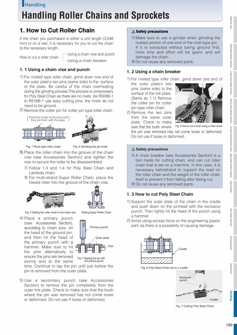
1. How to Cut Roller ChainIf the chain you purchased is either a unit length (3,048 mm) or on a reel, it is necessary for you to cut the chain to the necessary length.
How to cut a roller chainUsing a chain vise and punch
Using a chain breaker
1. 1 Using a chain vise and punch
For riveted type roller chain, grind down one end of the outer plate's two pins (same side) to the surface of the plate. Be careful of the chain overheating during the grinding process.This process is unnecessary for Poly Steel Chain as there are no rivets. As RS08B-1 to RS16B-1 use easy cutting pins, the rivets do not need to be ground.Remove the cotter pin for cotter pin type roller chain.
1)
2)
Grind the rivets of the pins untilthey are flush with the plate.( )
Fig. 1 Rivet-type roller chain
Fig. 4 Tapping the pin with the primary punch
Fig. 2 Grinding the pin ends
Place the roller chain into the groove of the chain vise (see Accessories Section) and tighten the vise to secure the roller to be disassembled.
Follow 1.3 and 1.4 for Poly Steel Chain and Lambda chain.For multi-strand Super Roller Chain, place the lowest roller into the groove of the chain vise.
3)
Use a secondary punch (see Accessories Section) to remove the pin completely from the outer link plate. Check to make sure that the bush where the pin was removed has not come loose or deformed. Do not use if loose or deformed.
5)
①
②
Fig. 3 Setting the roller chain in the chain vise Setting Super Roller Chain
Primary punch
Outer plate
Vise
Place a primary punch (see Accessories Section), according to chain size, on the head of the ground pin, and then hit the head of the primary punch with a hammer. Make sure to hit the pins alternatively to ensure the pins are removed evenly and at the same time. Continue to tap the pin until just before the pin is removed from the outer plate.
4)
Safety precautions
Make sure to use a grinder when grinding the riveted portion of one end of the rivet-type pin.If it is extracted without being ground first, more time and effort will be spent, and will damage the chain.Do not reuse any removed parts.
①
②
1. 2 Using a chain breaker
For riveted type roller chain, grind down one end of the outer plate's two pins (same side) to the surface of the link plate. (Same as 1.1) Remove the cotter pin for cotter pin type roller chain.Remove the two pins from the same outer plate. Check to make sure that the bush where the pin was removed has not come loose or deformed. Do not use if loose or deformed.
1)
2)
Fig. 5 How to cut a chain using a chain screw
Safety precautions
A chain breaker (see Accessories Section) is a tool made for cutting chain, and can cut roller chain that is set on a machine. In this case, it is necessary beforehand to support the load on the roller chain and the weight of the roller chain itself to prevent it from falling after being cut.Do not reuse any removed parts.
①
②
1. 3 How to cut Poly Steel Chain
1)
2)
Support the outer plate of the chain in the cradle and push down on the pinhead with the exclusive punch. Then lightly hit the head of the punch using a hammer.Avoid using excess force on the engineering plastic part, as there is a possibility of causing damage.
Cradle
Fig. 6 Poly Steel Chain set in a cradle
Exclusivepunch
Cradle
Fig. 7 Cutting Poly Steel Chain
190
Handling
Handling Roller Chains and Sprockets Befo
re Use
Standard R
oller Chains
Lube-Free Roller C
hainsH
eavy Duty R
oller Chains
Corrosion Resistant Roller ChainsS
pecialty Roller C
hainsS
pro
cketsP
in G
ear Drives
Accesso
riesS
election
Han
dlin
g

RS35 1 × 6 RS100 2.5×20
RS40 1 × 6 RS120 3 ×23
RS50 1.6× 8 RS140・RS160 4 ×24.5RS60 2 ×10 RS180 5 ×32RS80 2.5×14 RS200 5 ×37
1. 1 How to cut Lambda Chain
Support the chain with a chain vise and grind down one end of the outer link plate's two pins (same side) to the surface of the link plate. Be careful of the chain overheating during the grinding process. Grinding should be carried out slowly so as not to overheat the bushes in particular.Then cut the chain using an exclusive cradle (see Accessories section) and an RS Roller Chain punch. Important points for cutting are outlined in 4) and 5) in 1.1. However, use an exclusive cradle instead of a vise.Hit the pins alternatively when removing the pins with a punch. Take extra care not to remove or cause any damage to the bush. Do not use bush if it has come loose or been damaged.
1)
2)
3)
2. How to Connect Roller Chain2. 1 When connecting chain on sprocket teeth
Wind the chain around one of the sprockets so that both ends of the chain are facing each other on the sprocket.Insert the connecting link in the two end links of the chain.Insert the connecting link plate of the connecting link and fasten the plate using the clips/cotter pins or spring pins provided.When using a press-fit connecting link or F-Type (semi press-fit) connecting link, insert the connecting link plate by tapping it with a hammer until it moves into position.Then fasten it using the clips/cotter pins or spring pins provided.When using the sprocket teeth to connect the chain, take care not to damage the teeth, particularly when using a cast iron sprocket.
1)
When connecting or disconnecting roller chain, it is convenient to use the sprocket teeth. Please carry out the following steps.
2)3)
4)
5)
2. 2 When connecting between shafts
Wind the chain around the sprockets and pull the chain ends together using a chain puller (see Accessories section) or wire.Insert the connecting link in the two end links of the chain.Insert the connecting link plate of the connecting link and fasten the plate using the clips/cotter pins or spring pins provided.
1)
If a sprocket cannot be used due to layout, follow the procedures below.
2)
3)
Fig. 8 Connecting on a sprocket
Fig. 9 Connecting between shafts
2. 3 Clip and Cotter Pins
ClipClips are used for small size roller chain (under RS60) connecting links. When connecting the chain, the clip should be inserted securely into the slot of the pin on the connecting link after the connecting plate has been inserted on the pin. If the legs of the clips are spread too far they will not catch properly and will fall off during operation of the chain, causing accidents. Care should be taken when inserting them. The clip is generally installed opposite to the direction of travel for the chain as shown in Fig. 10.
1)
Cotter PinsTsubaki cotter pins are heat treated for Standard, Heavy-Duty, and Lambda Chain. The legs of the cotter pin should be bent approx. 60 degrees. Cotter pins should not be reused, and commercially available cotter pins other than those produced by Tsubaki should be avoided.
2)
Fig. 10 Direction in whichthe clip is installed
Fig. 11 Opening range of pins
RS Roller Chain cotter pin dimensions (These pins are not available commercially.)
Note: RS240 uses a roll pin.
Direction of travel
Cotter pin
Chain size Nominal cotter pin dimension Chain size Nominal cotter pin dimension
T-pin Z-pin
Safety Precautions
Avoid using offset links wherever possible by varying the center distance between shafts or using an idler.
In the case of pins and connecting link plate holes being press-fit type with F-Type or other connecting links, please avoid widening the connecting link plate hole or narrowing the pin diameter to make connecting easier, as this will result in a reduction in roller chain strength and cause an accident.
The outer link of cotter pin type roller chain can be used as a substitute for the connecting link. However, due to the press fit connection, the outer link plate must be carefully driven onto the pin parallel to the connecting link. If the connecting link plate is installed without due care to parallelism, chain damage or increased wear may result. Use caution as per (2) above.
Do not reuse press fit type link plates that have been detached, as the detachment results in a reduction in strength.
①
②
③
④
191
Handling
Handling Roller Chains and SprocketsBefo
re Use
Standard R
oller Chains
Lube-Free Roller C
hainsH
eavy Duty R
oller Chains
Corrosion Resistant Roller ChainsS
pecialty Roller C
hainsS
pro
cketsP
in G
ear Drives
Accesso
riesS
election
Han
dlin
g

SAE10W32
SAE2068
SAE30100
SAE40150
SAE50220
〃 68 〃 100 〃 150 〃 220
SAE(cSt40℃)
C
-10°C to to to to to to to to0°C 0°C 40°C 40°C 50°C 50°C 60°C -10°C 0°C 0°C 40°C 40°C 50°C 50°C 60°C
RS50 SAE10W SAE20 SAE30 SAE40SAE10W SAE20 SAE30 SAE40
RS60 / 80SAE20 SAE30 SAE40
SAE50RS100SAE20 SAE30 SAE40 SAE50
RS120 SAE30 SAE40 SAE50
-50°C to-25°C -25°C 0°C -10°C 60°C 60°C 200°C 150°C 250°C
Shin-Etsu ChemicalKF50
Exxon MobileDTE Oil HH
Exxon MobileArtic OilC baby
See above
AⅠ・AⅡ・B
3. Roller Chain LubricationLubrication is very important in roller chain transmis-sion, and becomes especially important when stringent demands are placed on chain performance.When lubrication is not complete, even the most advanced transmission device will not realize its full service life. Under some conditions the device may wear out within a very short period of time. For this reason, exercise special care with respect to lubrication.
The main reason for oiling and lubing roller chain is to minimize wear elongation of the chain and prevent corro-sion. Wear elongation is caused by wear between the pin and bush in articulating parts.
1)
Roller chain is coated with oil before being packaged (except for stainless steel chain). This oil is a high grade oil that prevents rust and provides lubrication. The oil prevents the wear that frequently occurs in the initial stage of operation, and it works well with lubrication oil to maintain a high wear resistance.
2)
On the slack part of the chain, apply lubrication oil to the gap between each outer plate and inner plate. At the same time, apply oil between the bushes and rollers.
2)
Avoid wiping the oil coating off of delivered roller chain, and avoid washing the chain with detergent or other cleaning agents.
3)
3.1 Oil application locationsRoller chain wear occurs from wear between each pin and bush, and thus oil must be applied to these parts.
1)
For roller chain that does not articulate, oil the chain sufficiently and then apply a thick layer of grease around the roller chain to prevent corrosion.Sufficiently lube end fitting connections, even if these do not move.
2)
For roller chain that is used outdoors, contact with rain and snow will remove the lubrication and cause harmful corro-sion, and thus a cover or other protection should be installed.If rain or snow does fall on the chain, remove the moisture and then promptly lube the chain and coat it with a thick layer of grease.
3)
3.2 Chain used for liftingIn general the chain has no catenary parts. If possible, remove the load that acts on the roller chain before lubing the chain.
1)
1) SAE numbers (Table 1)
2) Commercially available lubrication (Table 2)
3) Examples of lubrication at low and high temperatures (Table 3)The following oils are available when roller chain is used at low or high temperatures. Regarding other brands, use an equivalent.
Manufacturer names are shown in no particular order
Lubrication methods are drip, manual, and brush.
Lubricant type
Ambient temperature
Chain number
Manufacturer name
Ambient andoperating temperature
Manufacturer nameLubrication name
or lower small pitch chain
JX Nippon Oil & Energy
〃 68 〃 100 〃 150 〃 220Showa Shell Sekiyu Terasu Oil C32
FBK Oil RO32
〃 68 〃 100 〃 150 〃 220Super Mulpus DX32
3.3 Recommended lubricating oils
or higher large pitch chain
Fig. 10 Oiling locations
to to to to
GE Toshiba SiliconTSF431
Toray Dow CorningSH510
Sato Special Oil Co.Hot Bearing Oil
#255Sato Special Oil Co.High Thermal Lube
#700
MatsukenMoresukohai Lube
L-150
〃 〃 〃 〃 BBExxon Mobile DTE Oil Light Heavy Medium Heavy Extra Heavy〃 68 〃 100 〃 150 〃 220Idemitsu Kosan Daphne Mechanic Oil 32
192
Befo
re Use
Standard R
oller Chains
Lube-Free Roller C
hainsH
eavy Duty R
oller Chains
Corrosion Resistant Roller ChainsS
pecialty Roller C
hainsS
pro
cketsP
in G
ear Drives
Accesso
riesS
election
Han
dlin
g
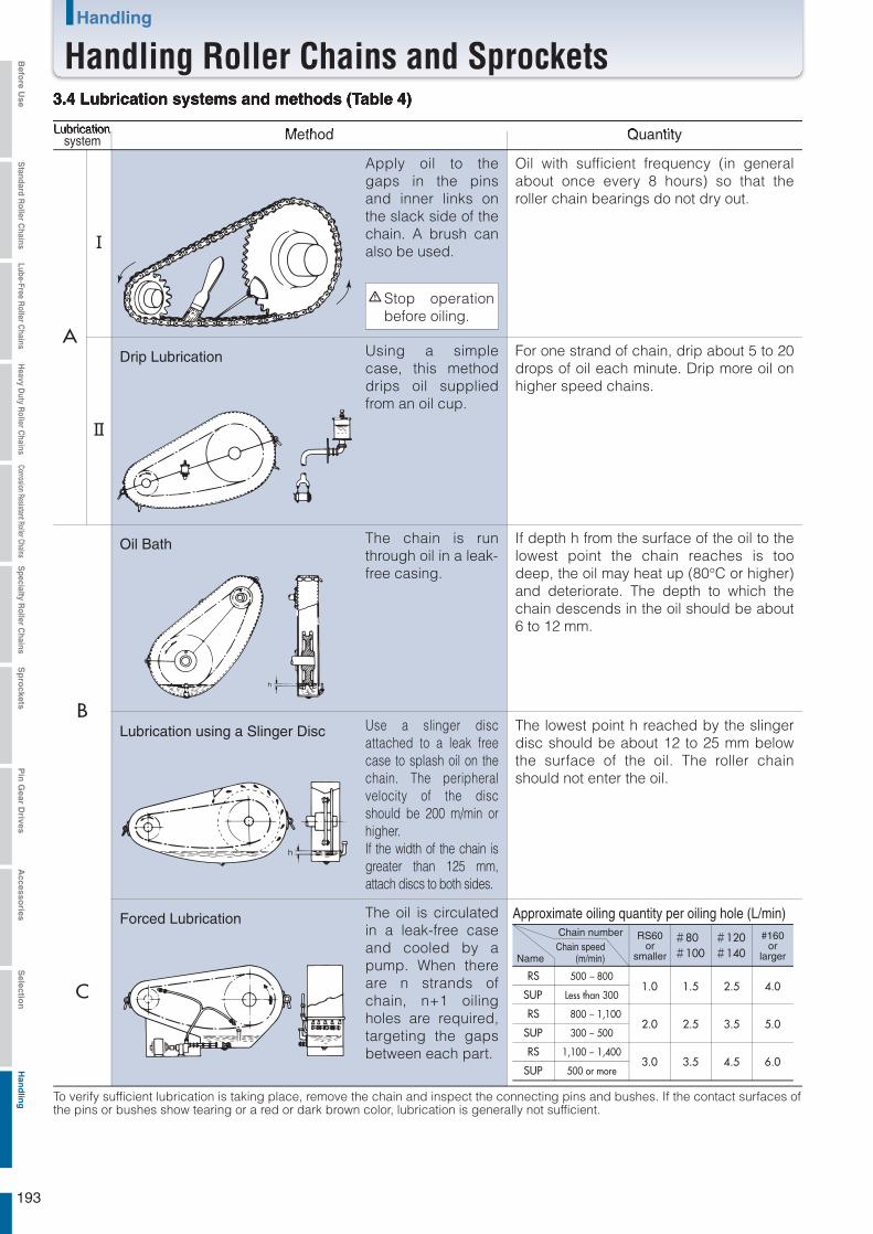
- 800
- 1,100
- 500
- 1,400
500
800
300
1,100
A
Ⅰ
Ⅱ
B
C
#80#100
#120#140
1.0
2.0
3.0
1.5
2.5
3.5
2.5
3.5
4.5
4.0
5.0
6.0
To verify sufficient lubrication is taking place, remove the chain and inspect the connecting pins and bushes. If the contact surfaces of the pins or bushes show tearing or a red or dark brown color, lubrication is generally not sufficient.
3.4 Lubrication systems and methods (Table 4)
Apply oil to the gaps in the pins and inner links on the slack side of the chain. A brush can also be used.
Oil with sufficient frequency (in general about once every 8 hours) so that the roller chain bearings do not dry out.
Using a simple case, this method drips oil supplied from an oil cup.
For one strand of chain, drip about 5 to 20 drops of oil each minute. Drip more oil on higher speed chains.
The chain is run through oil in a leak-free casing.
If depth h from the surface of the oil to the lowest point the chain reaches is too deep, the oil may heat up (80°C or higher) and deteriorate. The depth to which the chain descends in the oil should be about 6 to 12 mm.
Stop operation before oiling.
Lubricationsystem Method
Drip Lubrication
Oil Bath
Use a slinger disc attached to a leak free case to splash oil on the chain. The peripheral velocity of the disc should be 200 m/min or higher.If the width of the chain is greater than 125 mm, attach discs to both sides.
The lowest point h reached by the slinger disc should be about 12 to 25 mm below the surface of the oil. The roller chain should not enter the oil.
Lubrication using a Slinger Disc
The oil is circulated in a leak-free case and cooled by a pump. When there are n strands of chain, n+1 oiling holes are required, targeting the gaps between each part.
Forced Lubrication Approximate oiling quantity per oiling hole (L/min)
Quantity
Name
RS60or
smaller
#160or
larger
Chain numberChain speed
(m/min)
RS
SUP
RS
SUP
RS
SUP
Less than 300
500 or more
193
Handling
Handling Roller Chains and SprocketsBefo
re Use
Standard R
oller Chains
Lube-Free Roller C
hainsH
eavy Duty R
oller Chains
Corrosion Resistant Roller ChainsS
pecialty Roller C
hainsS
pro
cketsP
in G
ear Drives
Accesso
riesS
election
Han
dlin
g
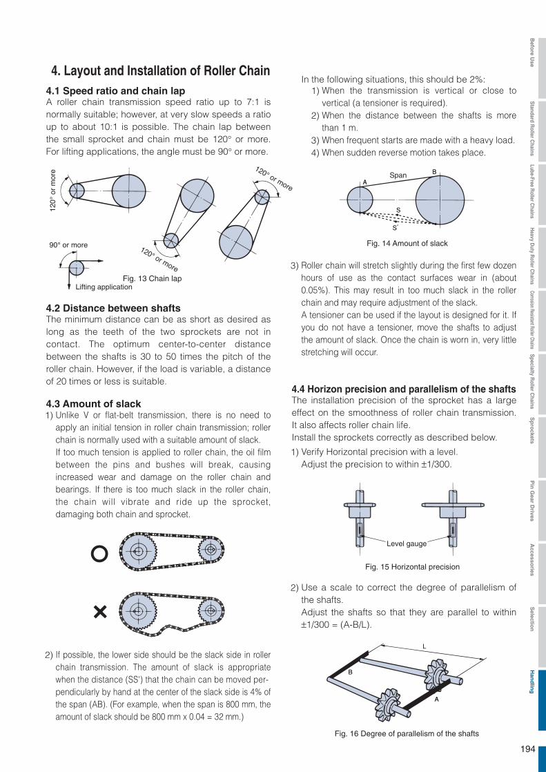
Fig. 13 Chain lap
Fig. 14 Amount of slack
Span
Fig. 15 Horizontal precision
Fig. 16 Degree of parallelism of the shafts
Lifting application
4. Layout and Installation of Roller Chain4.1 Speed ratio and chain lapA roller chain transmission speed ratio up to 7:1 is normally suitable; however, at very slow speeds a ratio up to about 10:1 is possible. The chain lap between the small sprocket and chain must be 120° or more. For lifting applications, the angle must be 90° or more.
The minimum distance can be as short as desired as long as the teeth of the two sprockets are not in contact. The optimum center-to-center distance between the shafts is 30 to 50 times the pitch of the roller chain. However, if the load is variable, a distance of 20 times or less is suitable.
4.2 Distance between shafts
The installation precision of the sprocket has a large effect on the smoothness of roller chain transmission. It also affects roller chain life.Install the sprockets correctly as described below.
4.4 Horizon precision and parallelism of the shafts4.3 Amount of slack
If possible, the lower side should be the slack side in roller chain transmission. The amount of slack is appropriate when the distance (SS') that the chain can be moved per-pendicularly by hand at the center of the slack side is 4% of the span (AB). (For example, when the span is 800 mm, the amount of slack should be 800 mm x 0.04 = 32 mm.)
In the following situations, this should be 2%:When the transmission is vertical or close to vertical (a tensioner is required).When the distance between the shafts is more than 1 m.When frequent starts are made with a heavy load.When sudden reverse motion takes place.
2)
Unlike V or flat-belt transmission, there is no need to apply an initial tension in roller chain transmission; roller chain is normally used with a suitable amount of slack.If too much tension is applied to roller chain, the oil film between the pins and bushes will break, causing increased wear and damage on the roller chain and bearings. If there is too much slack in the roller chain, the chain will vibrate and ride up the sprocket, damaging both chain and sprocket.
1)
Roller chain will stretch slightly during the first few dozen hours of use as the contact surfaces wear in (about 0.05%). This may result in too much slack in the roller chain and may require adjustment of the slack.A tensioner can be used if the layout is designed for it. If you do not have a tensioner, move the shafts to adjust the amount of slack. Once the chain is worn in, very little stretching will occur.
3)
Verify Horizontal precision with a level.Adjust the precision to within ±1/300.
1)
Use a scale to correct the degree of parallelism of the shafts.Adjust the shafts so that they are parallel to within ±1/300 = (A-B/L).
2)
1)
2)
3) 4)
Level gauge
194
Befo
re Use
Standard R
oller Chains
Lube-Free Roller C
hainsH
eavy Duty R
oller Chains
Corrosion Resistant Roller ChainsS
pecialty Roller C
hainsS
pro
cketsP
in G
ear Drives
Accesso
riesS
election
Han
dlin
g
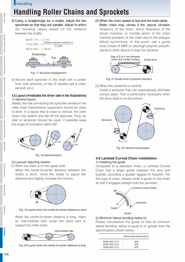
R
400500600
RS40-LMC-CU-IRS50-LMC-CU-IRS60-LMC-CU-I
: ±
: ±
: ±
Using a straightedge (or a scale), adjust the two sprockets so that they are parallel. Adjust to within the following values based on the distance between the shafts.
3)
Fig. 17 Sprocket misalignment
Fig. 21 Guide shoe to prevent vibration
Fig. 22 Vertical transmission
Fig. 18 General layout
Fig. 19 Layout when the center-to-center distance is short
Fig. 20 Layout when the center-to-center distance is long
Straightedge
Intermediate idler
Catenary side
Cat
enar
y si
de
Cat
enar
y si
de
Gap
Up to 1 m 1 mm
10 mm10,000
1 m to 10mDistance between shafts(mm)
10m or more
Secure each sprocket to the shaft with a power lock, lock sprocket, or key (if needed use a collar, set bolt, etc.).
4)
4.5 Layout ( indicates the driver side in the illustrations)1) General layoutIdeally, the line connecting the sprocket centers in the roller chain transmission equipment should be close to level. In a layout that is close to vertical, the roller chain may stretch and fall off the sprocket. Thus, an idler or tensioner should be used. If possible keep the angle of inclination within 60°.
4.6 Lambda Curved Chain installation1) Installing the guideCompared to a standard chain, a Lambda Curved Chain has a larger gutter between the pins and bushes, providing a greater degree of freedom. For this type of chain, please install a guide on the chain so that it engages straight onto the sprocket.
2) Minimum lateral bending radius (r)Please manufacture the guide so that its minimum lateral bending radius is equal to or greater than the specifications shown below.
2) Layouts requiring cautionWhen the slack is on the upper sideWhen the center-to-center distance between the shafts is short, move the shafts to adjust the distance and slightly increase the tension.
When the center-to-center distance is long, insert an intermediate idler under the slack part to support the roller chain.
(1)
When the chain speed is fast and the load variesRoller chain may vibrate if the natural vibration frequency of the chain, shock frequency of the driven machine, or chordal action of the chain (vertical pulsation of the chain due to the polygon effect) synchronize. In this event, use a guide shoe (made of NBR or ultra-high polymer polyeth-ylene) or other device to stop the vibration.
(2)
When the centerline is verticalInstall a tensioner that can automatically eliminate excess slack. This is particularly necessary when the drive shaft is on the bottom.
(3)
Gap of 2 to 4 mm betweenchain and contact surface
Tensioner
Tensioner
Lambda Curved Chain
Sprocket
Minimum lateral bending radius (r)
Guide
Guide
Guide shoe
195
Handling
Handling Roller Chains and SprocketsBefo
re Use
Standard R
oller Chains
Lube-Free Roller C
hainsH
eavy Duty R
oller Chains
Corrosion Resistant Roller ChainsS
pecialty Roller C
hainsS
pro
cketsP
in G
ear Drives
Accesso
riesS
election
Han
dlin
g
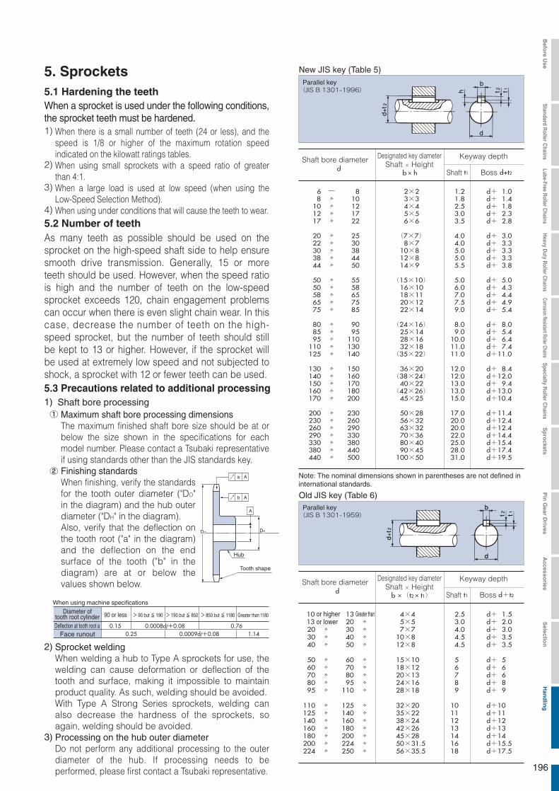
db ×(t2× t1) t1 d+t2
10 13 4×4 2.5 d+ 1.513 20 〃 5×5 3.0 d+ 2.020 〃 30 〃 7×7 4.0 d+ 3.030 〃 40 〃 10×8 4.5 d+ 3.540 〃 50 〃 12×8 4.5 d+ 3.5
50 〃 60 〃 15×10 5 d+ 560 〃 70 〃 18×12 6 d+ 670 〃 80 〃 20×13 7 d+ 680 〃 95 〃 24×16 8 d+ 895 〃 110 〃 28×18 9 d+ 9
110 〃 125 〃 32×20 10 d+10125 〃 140 〃 35×22 11 d+11140 〃 160 〃 38×24 12 d+12160 〃 180 〃 42×26 13 d+13180 〃 200 〃 45×28 14 d+14200 〃 224 〃 50×31.5 16 d+15.5224 〃 250 〃 56×35.5 18 d+17.5
db× h t1 d+t2
6 - 8 2×2 1.2 d+ 1.08 〃 10 3×3 1.8 d+ 1.4
10 〃 12 4×4 2.5 d+ 1.812 〃 17 5×5 3.0 d+ 2.317 〃 22 6×6 3.5 d+ 2.8
20 〃 25 (7×7) 4.0 d+ 3.022 〃 30 8×7 4.0 d+ 3.330 〃 38 10×8 5.0 d+ 3.338 〃 44 12×8 5.0 d+ 3.344 〃 50 14×9 5.5 d+ 3.8
50 〃 55 (15×10) 5.0 d+ 5.050 〃 58 16×10 6.0 d+ 4.358 〃 65 18×11 7.0 d+ 4.465 〃 75 20×12 7.5 d+ 4.975 〃 85 22×14 9.0 d+ 5.4
440 〃 500 100×50 31.0 d+19.5
80 〃 90 (24×16) 8.0 d+ 8.085 〃 95 25×14 9.0 d+ 5.495 〃 110 28×16 10.0 d+ 6.4
110 〃 130 32×18 11.0 d+ 7.4125 〃 140 (35×22) 11.0 d+11.0
130 〃 150 36×20 12.0 d+ 8.4140 〃 160 (38×24) 12.0 d+12.0150 〃 170 40×22 13.0 d+ 9.4160 〃 180 (42×26) 13.0 d+13.0170 〃 200 45×25 15.0 d+10.4
200 〃 230 50×28 17.0 d+11.4230 〃 260 56×32 20.0 d+12.4260 〃 290 63×32 20.0 d+12.4290 〃 330 70×36 22.0 d+14.4
380 〃 440 90×45 28.0 d+17.4330 〃 380 80×40 25.0 d+15.4
DO DH
Aa
Ab
A
90 or less > 90 but ≦ 190 > 190 but ≦ 850 > 850 but ≦ 1180 Greater than 1180
0.15 0.0008df+0.08 0.76 0.25 0.0009df+0.08 1.14
5. Sprockets5.1 Hardening the teeth
When there is a small number of teeth (24 or less), and the speed is 1/8 or higher of the maximum rotation speed indicated on the kilowatt ratings tables.When using small sprockets with a speed ratio of greater than 4:1.When a large load is used at low speed (when using the Low-Speed Selection Method).When using under conditions that will cause the teeth to wear.
1)
When a sprocket is used under the following conditions, the sprocket teeth must be hardened.
2)
5.3 Precautions related to additional processing
3)
4)5.2 Number of teethAs many teeth as possible should be used on the sprocket on the high-speed shaft side to help ensure smooth drive transmission. Generally, 15 or more teeth should be used. However, when the speed ratio is high and the number of teeth on the low-speed sprocket exceeds 120, chain engagement problems can occur when there is even slight chain wear. In this case, decrease the number of teeth on the high-speed sprocket, but the number of teeth should still be kept to 13 or higher. However, if the sprocket will be used at extremely low speed and not subjected to shock, a sprocket with 12 or fewer teeth can be used.
Shaft bore processingMaximum shaft bore processing dimensionsThe maximum finished shaft bore size should be at or below the size shown in the specifications for each model number. Please contact a Tsubaki representative if using standards other than the JIS standards key.Finishing standardsWhen finishing, verify the standards for the tooth outer diameter ("DO" in the diagram) and the hub outer diameter ("DH" in the diagram).Also, verify that the deflection on the tooth root ("a" in the diagram) and the deflection on the end surface of the tooth ("b" in the diagram) are at or below the values shown below.
1)
Sprocket weldingWhen welding a hub to Type A sprockets for use, the welding can cause deformation or deflection of the tooth and surface, making it impossible to maintain product quality. As such, welding should be avoided.With Type A Strong Series sprockets, welding can also decrease the hardness of the sprockets, so again, welding should be avoided.Processing on the hub outer diameterDo not perform any additional processing to the outer diameter of the hub. If processing needs to be performed, please first contact a Tsubaki representative.
2)
①
②
3)
Hub
Tooth shape
When using machine specifications
New JIS key (Table 5)
Old JIS key (Table 6)
Parallel key
Parallel key
Diameter oftooth root cylinderDeflection at tooth root a
Face runout
Shaft bore diameter Designated key diameter Keyway depth
Shaft BossShaft × Height
Shaft bore diameter Designated key diameterShaft × Height
Keyway depth
Note: The nominal dimensions shown in parentheses are not defined in international standards.
Shaft Boss
or higher Greater thanor lower
196
Befo
re Use
Standard R
oller Chains
Lube-Free Roller C
hainsH
eavy Duty R
oller Chains
Corrosion Resistant Roller ChainsS
pecialty Roller C
hainsS
pro
cketsP
in G
ear Drives
Accesso
riesS
election
Han
dlin
g

Ⅱ
Ⅲ
Ⅰ
6. Chain Test RunAfter installing the chain, carry out a test run and check the following items before you actually start running the chain.
6.1 Pre-test RunConnecting link plates, clips, and cotter pins are installed correctly.Chain slack has been properly adjusted.Adequate lubrication is available.The chain is not touching the chain case.The roller chain path is clean and free from obstructions.
1)
2)3)4)5)
6.2 Test RunThere should be no strange noises. Make sure the chain does not touch the case.Look for excessive chain vibration.Make sure the chain does not run up on the sprockets.Ensure that the chain is not jammed into the sprockets.The chain should articulate smoothly.
1)
2)3)4)5)
Check the inspection checklist if there are any problems, and ensure roller chain and sprocket are correctly installed.
7. Roller Chain InspectionIn general, roller chain life is said to be reached when parts are damaged or when 1.5% wear elongation occurs. See 6) in 7.3. Try to replace the chain before these conditions occur.If roller chain selection and operating conditions are suitable, you can expect rather long life with no unexpected trouble from the chain. However, wear will progress between the pins and bushes after long periods. The following should be noted and inspected.
1)
2)
7.1 Inspection Checklist (Table 7)
Procedures
Step
Step
Step
Method Inspection items Reference pagefor details
Visually check the chain
during operation and look
for any abnormalities.
1.
2.
3.
4.
5.
6.
7.
There should be no strange noises.
Look for excessive chain vibration.
Make sure the chain does not run up on the sprockets.
The chain is not jammed into the sprockets.
There are no stiff areas during articulation.
Adequate lubrication is available (lubricating system and quantity of oil).
Make sure the chain doesn't touch the case.
Inspection
points are on the
following pages
and on the
troubleshooting
pages.
Stop the chain and
carefully inspect each
part of the chain and
sprocket.
1.
2.
3.
4.
5.
6.
Check the external cleanliness, corrosion, and lubrication conditions; also, look for scratches or other damage to the plate side and edge surfaces, pin edges, and roller surfaces.
Inspect for pin rotation and inspect the clearance between plates and pins.
Inspect the sprocket teeth surfaces and teeth side surfaces for scratches or marks.
Measure the wear elongation of the chain.
Check the articulation of the chain and rotation of the rollers.
When using an end fitting for lifting applications, inspect the wear of the end bolts and the wear of the connecting plate pins. Also, check for proper installation at the same time.
In order to investigate in more
detail, remove the roller chain
and inspect it visuallly or check
it with measuring instruments.
1. The inspection items are identical to those in Step Ⅱ except in more detail.
197
Handling
Handling Roller Chains and SprocketsBefo
re Use
Standard R
oller Chains
Lube-Free Roller C
hainsH
eavy Duty R
oller Chains
Corrosion Resistant Roller ChainsS
pecialty Roller C
hainsS
pro
cketsP
in G
ear Drives
Accesso
riesS
election
Han
dlin
g

7.2 Inspection intervalsRegular inspection of roller chain is recommend at one month intervals. Inspection should be carried out at shorter intervals in:
Special or corrosive environments.High speeds with sudden stoppage.Lifting or indexing operations.
1)2)3)
7.3 Inspection requirements for ordinary transmission
Inspection lubrication conditions During operation, check to see if there is lubrication in the clearance between the outer plate and inner plate. Also, check if the chain or rotating disc is immersed in lubricating oil.When the chain is stationary, the chain surface will generally appear dirty from wear dust if lubrication is unsatisfactory. This is especially the case between the link plates.When the chain is removed, connecting link pins and the edge of the inside of the bushes should be checked. If there are any scratches, or red or reddish-brown coloration, lubrication is improper or insufficient.
1)①
②
③
Inspecting link platesIf repeat loads over the maximum allowable load are put on the chain, there is a strong possibility of fatigue breakage of the link plates. It is difficult to notice initial cracking from fatigue breakage simply from external observation. Usually, a crack develops at the edge of a hole or at the side of the link plate, as shown in the illustrations below. The presence of cracks should be checked carefully. Fatigue breakage progresses little by little, so it can be noticed with close attention.
2)①
②
Positions where cracksare likely to develop Example of a crack
Fig. 23 Cracks on the link plates
Fig. 24 Wear on the edges of the link plates
When wear occurs from sliding between the edges of the plates and the guides, it is necessary to adjust the position of either the chain or the guides. The allowable wear on the link plates is limited to 5% of their height.
③
Inspecting PinsWhen the pins rotate, the roller chain must be completely replaced with new chain. This also applies to the connecting pins. By removing the connecting parts it is possible to see the conditions of wear and rust on the surfaces of the pins.
3)
Correct position Rotated position
Fig. 25 Rotation of the pins
Inspecting rollersAs with the link plates, if rollers are also subjected to loads over the maximum allowable load, the repeated impact load between the chain and the sprockets may cause fatigue breakage to occur. The roller should be checked in the same way as the link plate.If foreign objects interfere with the engagement of the roller and sprocket, the roller may be damaged and a crack may develop. Careful attention should be paid to the above. Furthermore, with high-speed operations, even if foreign objects do not interfere with engagement, cracks may appear from the impact with the sprocket teeth.
4)①
②
Fig. 26 Cracks on the rollers
Chains damaged by fatigue breakage from the rollers must be completely replaced, as each part has received the same amount of repeated load.Also check for poor roller rotation.
③
④
Inspecting sprocketsChain and sprocket engagement can be checked by observing the roller and teeth surface. Proper engagement is when the contact area is uniform with point A in the illstration. If the contact area is lopsided or the sides of the teeth are wearing away (point B), this may have been caused from improper installation of the sprockets or twisting of the roller chain. In this case, rechecking/readjustment is necessary.The normal point of impact is slightly up from the tooth root. However, when initial tension is applied to the chain and tension remains on the slack side, the roller will slightly touch the tooth root. However, point A receives the strongest impact.
5)①
②
H × 5%
198
Befo
re Use
Standard R
oller Chains
Lube-Free Roller C
hainsH
eavy Duty R
oller Chains
Corrosion Resistant Roller ChainsS
pecialty Roller C
hainsS
pro
cketsP
in G
ear Drives
Accesso
riesS
election
Han
dlin
g
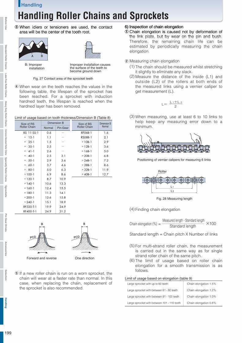
L=L 1+L 2
2
×100
RS 11-SS-1 0.6 -
〃 15-1 1.1 -
〃 25-1 1.5 -
〃 35-1 2.5 -
〃 41-1 2.6 -
〃 40-1 2.5 3.1
〃 50-1 2.9 3.6
〃 60-1 3.7 4.6
〃 80-1 5.0 6.3
〃100-1 6.9 8.6
〃120-1 8.7 10.9
〃140-1 10.6 13.3
〃160-1 12.4 15.5
〃180-1 11.3 14.1
〃200-1 12.6 15.8
〃240-1 15.1 18.9
RF320-T-1 19.9 24.9
RF400-T-1 24.9 31.2
RF06B-1 1.6
RS08B-1 2.1
〃10B-1 2.9
〃12B-1 3.6
〃16B-1 5.0
〃20B-1 6.8
〃24B-1 7.2
〃28B-1 8.6
〃32B-1 11.9
〃40B-1 12.7
When idlers or tensioners are used, the contact area will be the center of the tooth root.
③
When wear on the teeth reaches the values in the following table, the lifespan of the sprocket has been reached. For a sprocket with induction hardned teeth, the lifespan is reached when the hardned layer has been removed.
④
B: Improper installation
Improper installation causesthe surface of the teeth tobecome ground down
Fig. 27 Contact area of the sprocket teeth
Fig. 28 Measuring length
Limit of usage based on tooth thickness/Dimension B (Table 8)Dimension B Dimension B
NormalSize of RS
Roller ChainSize of BS
Roller ChainNormal Pin-Gear
Forward and reverse One direction
Positioning of vernier calipers for measuring 6 links
Roller
If a new roller chain is run on a worn sprocket, the chain will wear at a faster rate than normal. In this case, when replacing the chain, replacement of the sprocket is also recommended.
⑤
Inspection of chain elongationChain elongation is caused not by deformation of the link plate, but by wear on the pin and bush. Therefore, the remaining chain life can be estimated by periodically measuring the chain elongation.
Measuring chain elongationThe chain should be measured whilst stretching it slightly to eliminate any slack.Measure the distance of the inside (L1) and outside (L2) of the rollers at both ends of the measured links using a vernier caliper to get measurement (L).
6)①
②
(1)
When measuring, use at least 6 to 10 links to help keep any measuring error down to a minimum.
(3)
(2)
Finding chain elongation(4)
Chain elongation (%) =Measured length - Standard length
Standard length
Standard length = Chain pitch X Number of links
For multi-strand roller chain, the measurement is carried out in the same way as for single strand roller chain of the same pitch.The limit of usage based on roller chain elongation for a smooth transmission is as follows.
(5)
(6)
Limit of usage based on elongation (table 9)
Large sprocket with up to 60 teeth Chain elongation 1.5%
Large sprocket with between 61 - 80 teeth Chain elongation 1.2%
Large sprocket with between 81 - 100 teeth Chain elongation 1.0%
Large sprocket with between 101 - 110 teeth Chain elongation 0.8%
199
Handling
Handling Roller Chains and SprocketsBefo
re Use
Standard R
oller Chains
Lube-Free Roller C
hainsH
eavy Duty R
oller Chains
Corrosion Resistant Roller ChainsS
pecialty Roller C
hainsS
pro
cketsP
in G
ear Drives
Accesso
riesS
election
Han
dlin
g
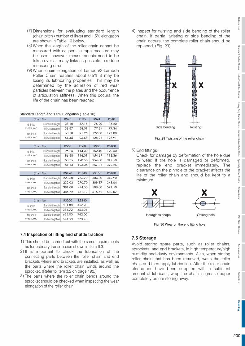
RS25 RS35 RS41
63.50 95.25 127.00
64.45 96.68 128.91
RS40
38.10 57.15 76.20 76.20
38.67 58.01 77.34 77.34
127.00
128.91
RS50 RS60 RS80
158.75 190.50 254.00
161.13 193.36 257.81
RS100
95.25 114.30 152.40 190.50
96.68 116.01 154.69 193.36
317.50
322.26
RS120 RS140 RS160
381.00 444.50 508.00
386.72 451.17 515.62
RS180
228.60 266.70 304.80 342.90
232.03 270.70 309.37 348.04
571.50
580.07
RS200 RS240
381.00 457.20
386.72 464.06
635.00 762.00
644.53 773.43
Dimensions for evaluating standard length (chain pitch x number of links) and 1.5% elongation are shown in Table 10 below.When the length of the roller chain cannot be measured with calipers, a tape measure may be used; however, measurements need to be taken over as many links as possible to reduce measuring error.When chain elongation of Lambda/X-Lambda Roller Chain reaches about 0.5% it may be losing its lubricating properties. This may be determined by the adhesion of red wear particles between the plates and the occurrence of articulation stiffness. When this occurs, the life of the chain has been reached.
(7)
(8)
(9)
Standard Length and 1.5% Elongation (Table 10)Chain No.
Chain No.
Chain No.
Chain No.
6 linksmeasured
6 linksmeasured
Standard length
Standard length
1.5% elongation
1.5% elongation
Standard length
Standard length
1.5% elongation
1.5% elongation
10 linksmeasured
10 linksmeasured
6 linksmeasured
Standard length
Standard length
1.5% elongation
1.5% elongation10 links
measured
6 linksmeasured
Standard length
Standard length
1.5% elongation
1.5% elongation10 links
measured
Inspect for twisting and side bending of the roller chain. If partial twisting or side bending of the chain occurs, the complete roller chain should be replaced. (Fig. 29)
4)
Fig. 29 Twisting of the roller chain
Side bending Twisting
7.4 Inspection of lifting and shuttle traction
This should be carried out with the same requirements as for ordinary transmission shown in item 6.3.It is important to check the lubrication of the connecting parts between the roller chain and end brackets where end brackets are installed, as welll as the parts where the roller chain winds around the sprocket. (Refer to item 3.2 on page 192.)The parts where the roller chain bends around the sprocket should be checked when inspecting the wear elongation of the roller chain.
1)
2)
3)
End fittingsCheck for damage by deformation of the hole due to wear. If the hole is damaged or deformed, replace the end bracket immediately. The clearance on the pinhole of the bracket affects the life of the roller chain and should be kept to a minimum
5)
Fig. 30 Wear on the end fitting hole
Hourglass shape Oblong hole
7.5 StorageAvoid storing spare parts, such as roller chains, sprockets, and end brackets, in high temperature/high humidity and dusty environments. Also, when storing roller chain that has been removed, wash the roller chain and then apply lubrication. After the roller chain clearances have been supplied with a sufficient amount of lubricant, wrap the chain in grease paper completely before storing away.
200
Befo
re Use
Standard R
oller Chains
Lube-Free Roller C
hainsH
eavy Duty R
oller Chains
Corrosion Resistant Roller ChainsS
pecialty Roller C
hainsS
pro
cketsP
in G
ear Drives
Accesso
riesS
election
Han
dlin
g
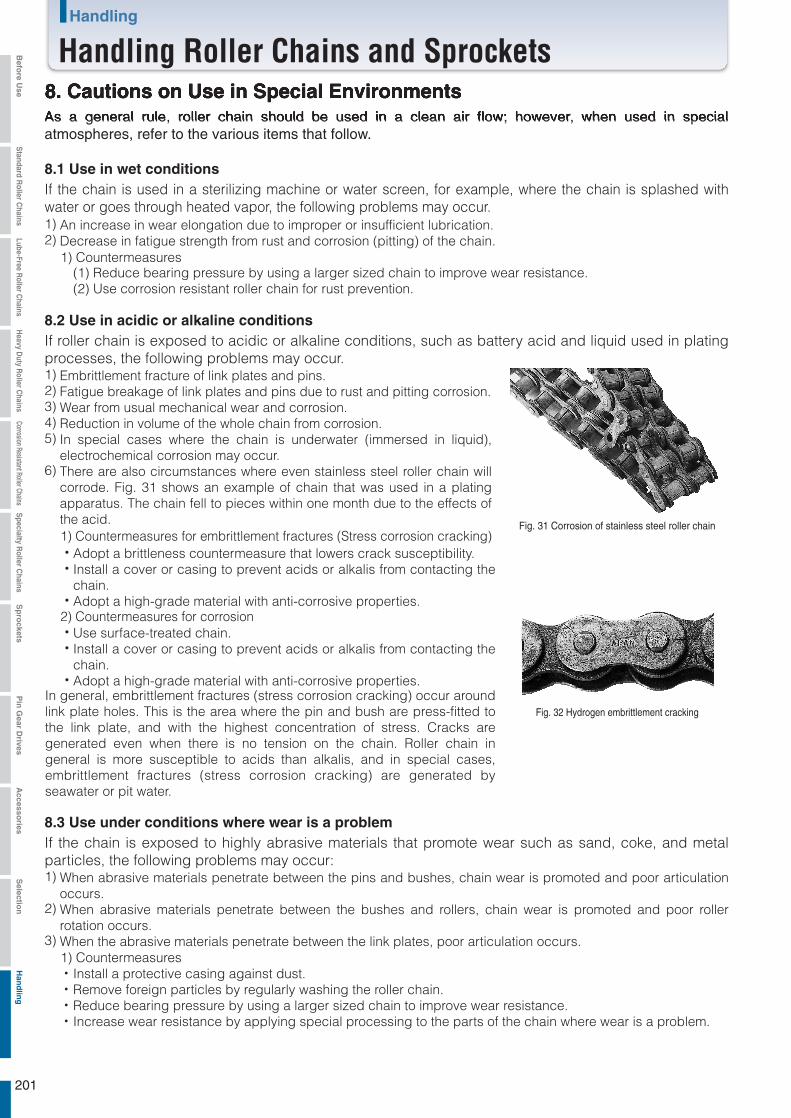
As a general rule, roller chain should be used in a clean air flow; however, when used in special atmospheres, refer to the various items that follow.
8. Cautions on Use in Special Environments
8.1 Use in wet conditions
An increase in wear elongation due to improper or insufficient lubrication.Decrease in fatigue strength from rust and corrosion (pitting) of the chain.
1)2)
If the chain is used in a sterilizing machine or water screen, for example, where the chain is splashed with water or goes through heated vapor, the following problems may occur.
(1) Reduce bearing pressure by using a larger sized chain to improve wear resistance.(2) Use corrosion resistant roller chain for rust prevention.
8.2 Use in acidic or alkaline conditionsIf roller chain is exposed to acidic or alkaline conditions, such as battery acid and liquid used in plating processes, the following problems may occur.
Embrittlement fracture of link plates and pins.Fatigue breakage of link plates and pins due to rust and pitting corrosion.Wear from usual mechanical wear and corrosion.Reduction in volume of the whole chain from corrosion.In special cases where the chain is underwater (immersed in liquid), electrochemical corrosion may occur.There are also circumstances where even stainless steel roller chain will corrode. Fig. 31 shows an example of chain that was used in a plating apparatus. The chain fell to pieces within one month due to the effects of the acid.
1)2)3)4)5)
6)
1) Countermeasures
1) Countermeasures for embrittlement fractures (Stress corrosion cracking)
2) Countermeasures for corrosion
1) Countermeasures
Adopt a brittleness countermeasure that lowers crack susceptibility.Install a cover or casing to prevent acids or alkalis from contacting the chain.Adopt a high-grade material with anti-corrosive properties.
・・
・
Install a protective casing against dust.Remove foreign particles by regularly washing the roller chain.Reduce bearing pressure by using a larger sized chain to improve wear resistance.Increase wear resistance by applying special processing to the parts of the chain where wear is a problem.
・・・・
Use surface-treated chain.Install a cover or casing to prevent acids or alkalis from contacting the chain.Adopt a high-grade material with anti-corrosive properties.
In general, embrittlement fractures (stress corrosion cracking) occur around link plate holes. This is the area where the pin and bush are press-fitted to the link plate, and with the highest concentration of stress. Cracks are generated even when there is no tension on the chain. Roller chain in general is more susceptible to acids than alkalis, and in special cases, embrittlement fractures (stress corrosion cracking) are generated by seawater or pit water.
・・
・
8.3 Use under conditions where wear is a problem If the chain is exposed to highly abrasive materials that promote wear such as sand, coke, and metal particles, the following problems may occur:
When abrasive materials penetrate between the pins and bushes, chain wear is promoted and poor articulation occurs.When abrasive materials penetrate between the bushes and rollers, chain wear is promoted and poor roller rotation occurs.When the abrasive materials penetrate between the link plates, poor articulation occurs.
1)
2)
3)
Fig. 31 Corrosion of stainless steel roller chain
Fig. 32 Hydrogen embrittlement cracking
201
Handling
Handling Roller Chains and SprocketsBefo
re Use
Standard R
oller Chains
Lube-Free Roller C
hainsH
eavy Duty R
oller Chains
Corrosion Resistant Roller ChainsS
pecialty Roller C
hainsS
pro
cketsP
in G
ear Drives
Accesso
riesS
election
Han
dlin
g
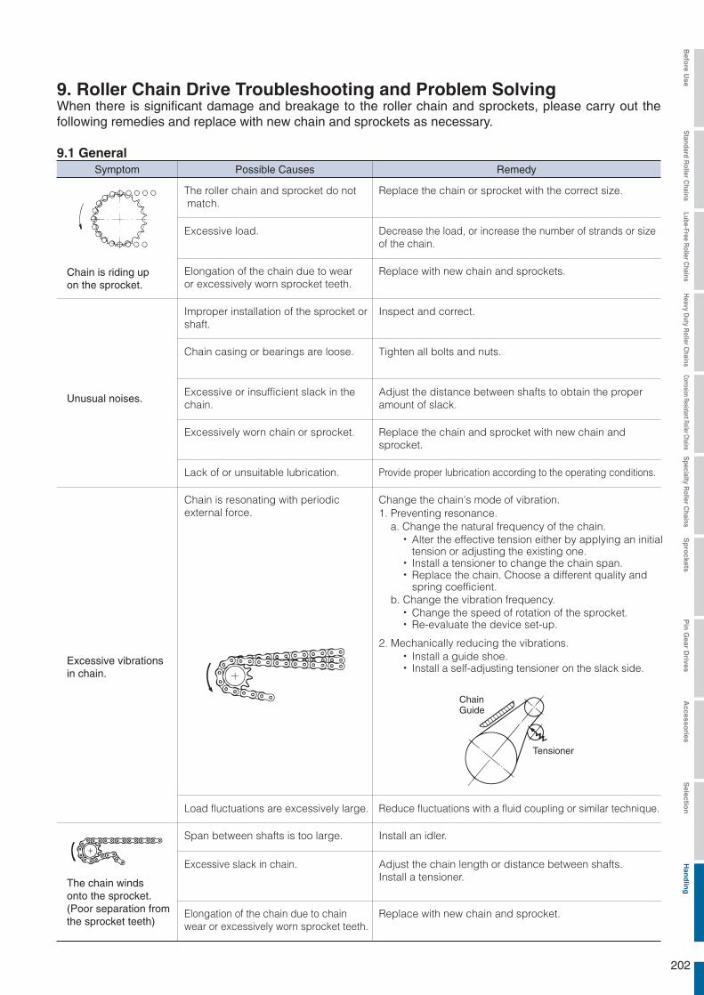
・
・・
・・
・・
When there is significant damage and breakage to the roller chain and sprockets, please carry out the following remedies and replace with new chain and sprockets as necessary.
9. Roller Chain Drive Troubleshooting and Problem Solving
9.1 GeneralSymptom Possible Causes Remedy
Chain is riding up on the sprocket.
The roller chain and sprocket do not match.
Replace the chain or sprocket with the correct size.
Excessive load. Decrease the load, or increase the number of strands or sizeof the chain.
Elongation of the chain due to wear or excessively worn sprocket teeth.
Replace with new chain and sprockets.
Unusual noises.
Improper installation of the sprocket orshaft.
Inspect and correct.
Chain casing or bearings are loose. Tighten all bolts and nuts.
Excessive or insufficient slack in the chain.
Adjust the distance between shafts to obtain the properamount of slack.
Excessively worn chain or sprocket. Replace the chain and sprocket with new chain andsprocket.
Provide proper lubrication according to the operating conditions.Lack of or unsuitable lubrication.
Excessive vibrations in chain.
Chain is resonating with periodicexternal force.
Change the chain's mode of vibration.1. Preventing resonance.
a. Change the natural frequency of the chain.
b. Change the vibration frequency.
Alter the effective tension either by applying an initialtension or adjusting the existing one. Install a tensioner to change the chain span.Replace the chain. Choose a different quality andspring coefficient.
Change the speed of rotation of the sprocket.Re-evaluate the device set-up.
2. Mechanically reducing the vibrations.Install a guide shoe.Install a self-adjusting tensioner on the slack side.
ChainGuide
Tensioner
Reduce fluctuations with a fluid coupling or similar technique.Load fluctuations are excessively large.
The chain winds onto the sprocket. (Poor separation from the sprocket teeth)
Install an idler.Span between shafts is too large.
Excessive slack in chain. Adjust the chain length or distance between shafts.Install a tensioner.
Replace with new chain and sprocket.Elongation of the chain due to chainwear or excessively worn sprocket teeth.
202
Befo
re Use
Standard R
oller Chains
Lube-Free Roller C
hainsH
eavy Duty R
oller Chains
Corrosion Resistant Roller ChainsS
pecialty Roller C
hainsS
pro
cketsP
in G
ear Drives
Accesso
riesS
election
Han
dlin
g
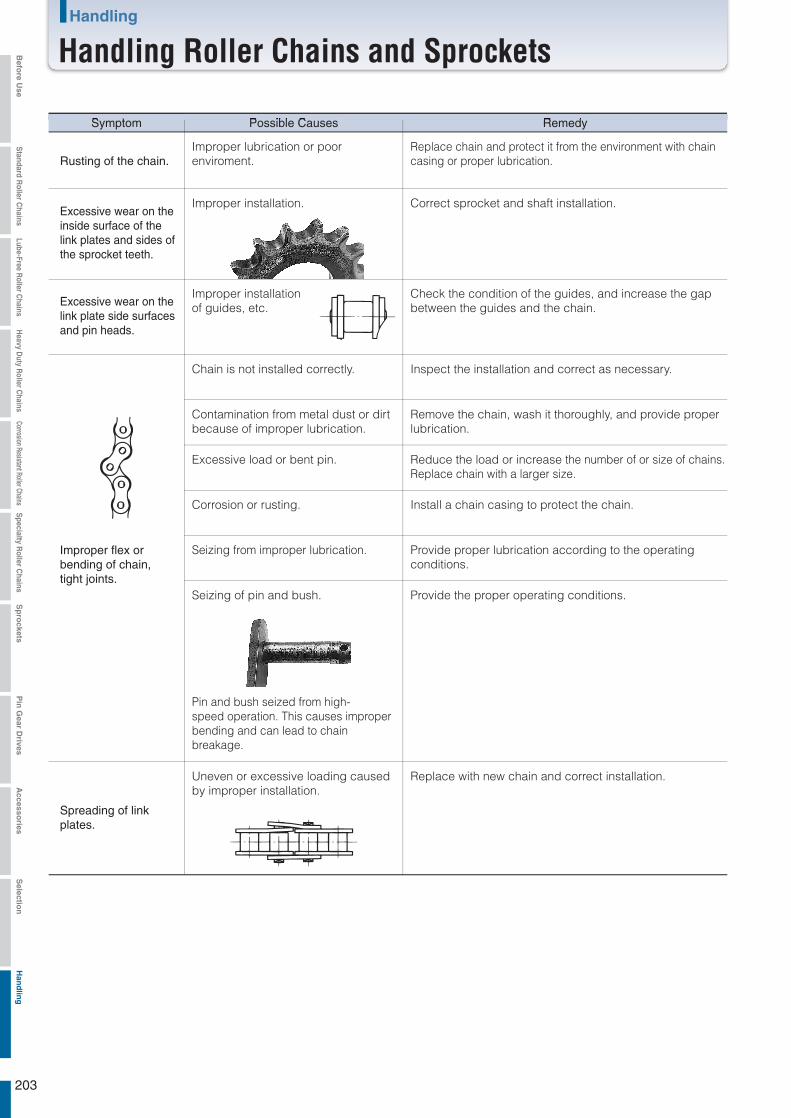
Symptom Possible Causes Remedy
Improper lubrication or poor enviroment.
Replace chain and protect it from the environment with chaincasing or proper lubrication.Rusting of the chain.
Excessive wear on theinside surface of thelink plates and sides ofthe sprocket teeth.
Improper installation. Correct sprocket and shaft installation.
Excessive wear on thelink plate side surfacesand pin heads.
Improper installationof guides, etc.
Check the condition of the guides, and increase the gapbetween the guides and the chain.
Improper flex orbending of chain,tight joints.
Chain is not installed correctly. Inspect the installation and correct as necessary.
Contamination from metal dust or dirtbecause of improper lubrication.
Remove the chain, wash it thoroughly, and provide properlubrication.
Excessive load or bent pin. Reduce the load or increase the number of or size of chains.Replace chain with a larger size.
Corrosion or rusting. Install a chain casing to protect the chain.
Seizing from improper lubrication. Provide proper lubrication according to the operatingconditions.
Seizing of pin and bush.
Pin and bush seized from high-speed operation. This causes improperbending and can lead to chainbreakage.
Provide the proper operating conditions.
Uneven or excessive loading causedby improper installation.
Replace with new chain and correct installation.
Spreading of linkplates.
203
Handling
Handling Roller Chains and SprocketsBefo
re Use
Standard R
oller Chains
Lube-Free Roller C
hainsH
eavy Duty R
oller Chains
Corrosion Resistant Roller ChainsS
pecialty Roller C
hainsS
pro
cketsP
in G
ear Drives
Accesso
riesS
election
Han
dlin
g
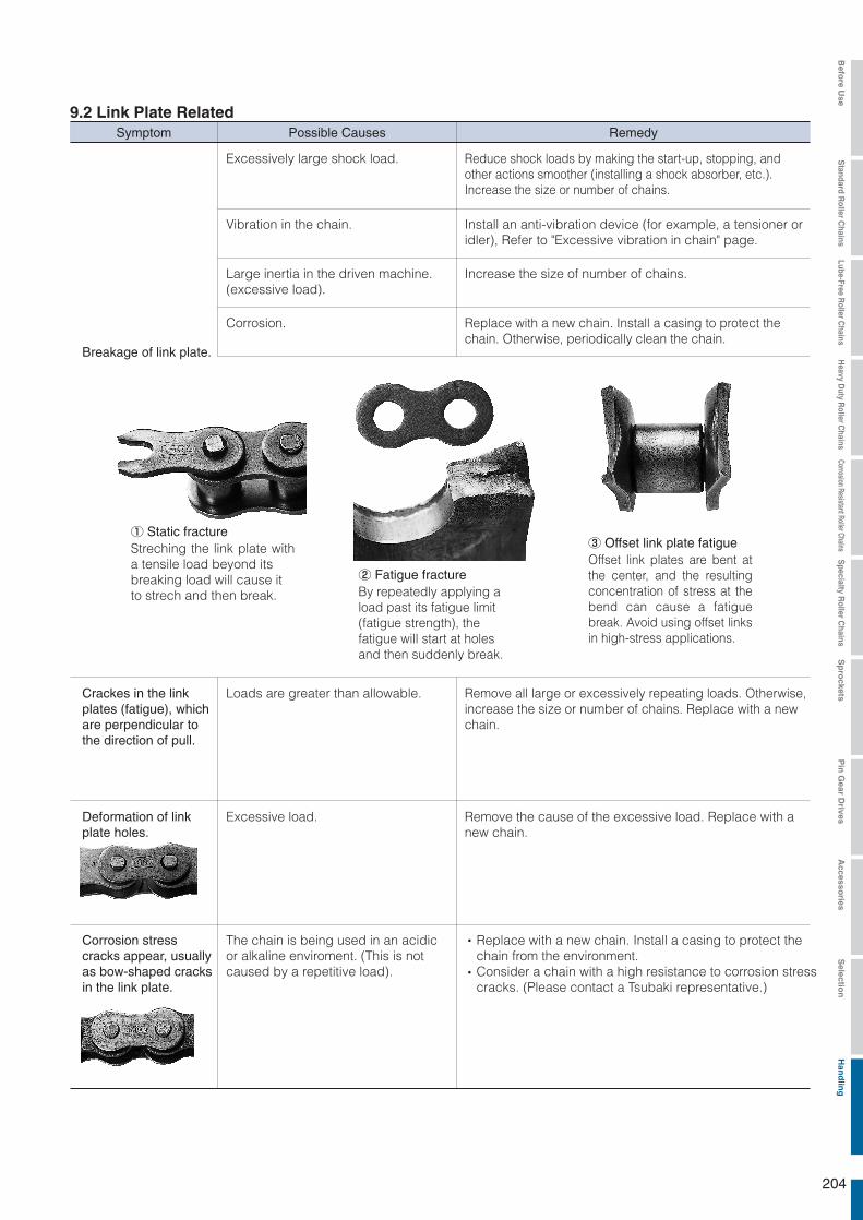
Symptom Possible Causes Remedy
9.2 Link Plate Related
Breakage of link plate.
Excessively large shock load.
Vibration in the chain.
Large inertia in the driven machine. (excessive load).
Corrosion.
Reduce shock loads by making the start-up, stopping, andother actions smoother (installing a shock absorber, etc.).Increase the size or number of chains.
Install an anti-vibration device (for example, a tensioner oridler), Refer to "Excessive vibration in chain" page.
Increase the size of number of chains.
Replace with a new chain. Install a casing to protect thechain. Otherwise, periodically clean the chain.
Streching the link plate with a tensile load beyond itsbreaking load will cause itto strech and then break.
① Static fracture
By repeatedly applying a load past its fatigue limit(fatigue strength), thefatigue will start at holesand then suddenly break.
② Fatigue fractureOffset link plates are bent at the center, and the resulting concentration of stress at the bend can cause a fatigue break. Avoid using offset links in high-stress applications.
③ Offset link plate fatigue
Remove all large or excessively repeating loads. Otherwise,increase the size or number of chains. Replace with a newchain.
Loads are greater than allowable.Crackes in the link plates (fatigue), whichare perpendicular tothe direction of pull.
Excessive load.Deformation of link plate holes.
Remove the cause of the excessive load. Replace with a new chain.
The chain is being used in an acidic or alkaline enviroment. (This is not caused by a repetitive load).
Corrosion stress cracks appear, usuallyas bow-shaped cracksin the link plate.
Replace with a new chain. Install a casing to protect thechain from the environment.Consider a chain with a high resistance to corrosion stresscracks. (Please contact a Tsubaki representative.)
・
・
204
Befo
re Use
Standard R
oller Chains
Lube-Free Roller C
hainsH
eavy Duty R
oller Chains
Corrosion Resistant Roller ChainsS
pecialty Roller C
hainsS
pro
cketsP
in G
ear Drives
Accesso
riesS
election
Han
dlin
g

RS11-SS-1, RS15-1, RS25-1, RS35-1
9.3 Pin RelatedSymptom Possible Causes Remedy
Symptom Possible Causes Remedy
Reduce shock loads by making the start-up, stopping, andother actions smoother.
Remove the large repetitive load. Otherwise, increase thesize or number of chains.
Excessively large shock loads.
Subject to a repetitive load greater than the fatigue limit of the pin.Breakage of pin.
Install a casing to protect the chain. Periodically clean and lubricate the chains.Corrosion.
The type of fracture found when subjecting the chain to the breakage test. Occurs when chain is subjected to a load greater than its breakage strength.
① Static fractureOccurs when the pin is repetitively subjected to loads greater than its fatigue limit. Re-check the size of the peak load and formulate a countermeasure.
② Fatigue fracture The pin is subjected to a large shock load and breaks. The side with the initiating point receives tensile load, and the fracture progresses from this point. A pin is especially susceptible to becoming weak with regard to bending when the surface of the pin has corroded. This type of phenomenon occurs quite easily.
③ Shock-induced bending fracture
Replace with new chain. Improve the lubrication or loadingconditions.Excessive load or improper lubrication.
Pin rotates or begins tostick out.
Normal
Operating a chain at high load without proper lubrication can create friction between the pin and bush, causing the pin to rotate. In this condition, the pin may come out, leading to chain breakage.
Replace with new chain immediately. Do not weld or reuse the pins. (Dispose of the old chain to be sure that it is not used again by mistake.) Also, if the pin head or link plate surface is worn, check the installation.
Improper initial lubrication at installation. Replace the connecting link. If pin wear is excessive, replace the chain also. Take special care to properly install the connecting section for devices such as end brackets used for lifting applications, etc.
Wear or rust occurs only at the connecting pin in a lifting application or similar operation.
9.4 Bush / Roller Related
Roller and/or bushsplits. (Falls off)
Choose a different chain according to the kW ratings table.Excessive load or speed of rotation.
Replace the chain. Provide adequate lubrication accordingto the operating conditions.Inadequate lubrication.
A bushed chain and not a roller chain is being used.
Roller does not rotate.The inner link plate is moving inward, orthe bush is cracked.
Replace with a new chain. Re-inspect the installation andload conditions.
Periodically clean the chain. Install a casing to protect thechain.
Foreign particles have gotten betweenthe bush and roller.
Fatigue fracture.Reached the point of fatigue during operation and eventually broke. Impact with the sprocket teeth at a force exceeding the chain's transmission capacity.
Roller is opening up.
Roller is becominghourglass shaped.
Excessive load.
Excessive load or inadequatelubrication.
Reduce the load. Provide adequate lubrication.
Replace with new chain. Improve the lubrication or loadingconditions.
205
Handling
Handling Roller Chains and SprocketsBefo
re Use
Standard R
oller Chains
Lube-Free Roller C
hainsH
eavy Duty R
oller Chains
Corrosion Resistant Roller ChainsS
pecialty Roller C
hainsS
pro
cketsP
in G
ear Drives
Accesso
riesS
election
Han
dlin
g
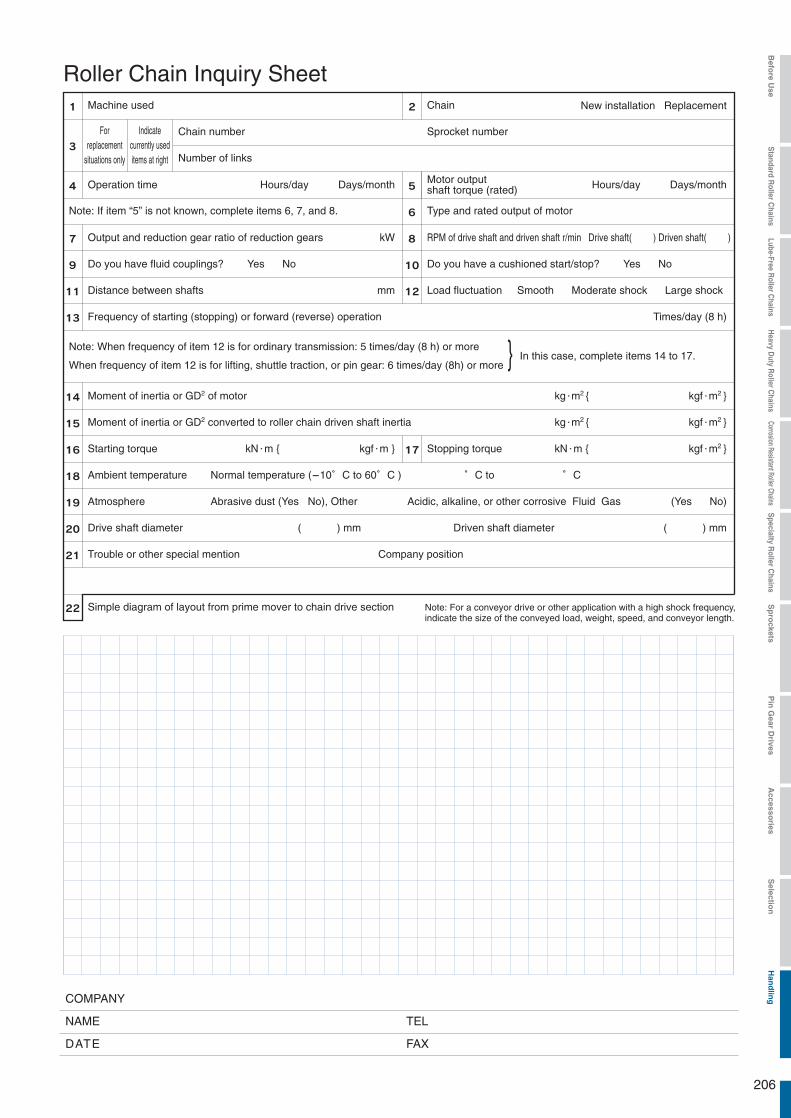
}
Roller Chain Inquiry SheetMachine used
Operation time
Output and reduction gear ratio of reduction gears
Note: When frequency of item 12 is for ordinary transmission: 5 times/day (8 h) or more
When frequency of item 12 is for lifting, shuttle traction, or pin gear: 6 times/day (8h) or more
Do you have fluid couplings? Yes No
Distance between shafts
Frequency of starting (stopping) or forward (reverse) operation
Moment of inertia or GD2 converted to roller chain driven shaft inertia
Starting torque
Ambient temperature Normal temperature (-10゜C to 60゜C )
Atmosphere
Drive shaft diameter
Trouble or other special mention
TELNAME
COMPANY
FAXDATE
Simple diagram of layout from prime mover to chain drive section Note: For a conveyor drive or other application with a high shock frequency, indicate the size of the conveyed load, weight, speed, and conveyor length.
Company position
Abrasive dust (Yes No), Other
゜C to ゜C
Stopping torquekN m { kgf m }
Moment of inertia or GD2 of motor
In this case, complete items 14 to 17.
Do you have a cushioned start/stop? Yes No
Load fluctuation Smooth Moderate shock Large shock
RPM of drive shaft and driven shaft r/min Drive shaft( ) Driven shaft( )kW
mm
( ) mm Driven shaft diameter ( ) mm
Note: If item “5” is not known, complete items 6, 7, and 8. Type and rated output of motor
Motor output shaft torque (rated)Hours/day Days/month Hours/day Days/month
Times/day (8 h)
(Yes No)
Forreplacement
situations only
Indicatecurrently useditems at right
Chain
Sprocket number
New installation Replacement
Chain number
Number of links
kN m { kgf m2 }
kg m2 { kgf m2 }
kg m2 { kgf m2 }
Acidic, alkaline, or other corrosive Fluid Gas
206
Befo
re Use
Standard R
oller Chains
Lube-Free Roller C
hainsH
eavy Duty R
oller Chains
Corrosion Resistant Roller ChainsS
pecialty Roller C
hainsS
pro
cketsP
in G
ear Drives
Accesso
riesS
election
Han
dlin
g

M E M O
207
For Safe UseWARNING Obey the following points in order to prevent hazardous situations.
1.
2.
3.
4.
5.
Products manufactured by Seller: (a) conform to the design and specifications, if any, expressly agreed to in writing by Seller; and (b) are free of defects in workmanship and materials at the time of shipment. The warranties set forth in the preceding sentence are exclusive of all other warranties, express or implied, and extend only to Buyer and to no other person. ALL WARRANTIES OF MERCHANTABILITY OR FITNESS FOR A PARTICULAR PURPOSE ARE HEREBY EXCLUDED.
NON-RELIANCEBuyer is not relying upon any advice, representations or warranties (except the warranties expressly set forth above) of Seller, or upon Seller's skill or judgment regarding the Seller's products.Buyer is solely responsible for the design and specifications of the products, including without limitation, the determination of suitability for Buyer's application of the products.
CLAIMS
INDEMNIFICATIONBuyer will indemnify, defend and hold Seller harmless from all loss, liability, damage and expense, including attorneys' fees, arising out of any claim (a) for infringement of any patent, trademark, copyright, misappropriation of trade secrets, unfair competition or similar charge by any products supplied by Seller in accordance with the design or specifications furnished by Buyer, or (b) arising out of or connected with the products or any items into which the products are incorporated, including, but not limited to, any claim for product liability (whether or not based on negligence or strict liability of Seller), breach of warranty, breach of contract or otherwise.
ENTIRE AGREEMENTThese terms and conditions constitute the entire agreement between Buyer and Seller and supersede any inconsistent terms and conditions, whether contained in Buyer's purchase order or otherwise, and whether made heretofore or hereafter.No statement or writing subsequent to the date hereof which purports to modify or add to the terms and conditions hereof shall be binding unless consented to in writing, which makes specific reference hereto, and which has been signed by the party against which enforcement thereof is sought. Seller reserves the right to change these terms and conditions without prior notice.
Do not use chains and accessories (accessories and parts) for anything other than their original purpose.Never perform additional processing on the chain.. Do not anneal the various parts of the chain.. Do not clean the chain with either acid or alkali, as they may cause cracking.. Do not electroplate the chain or its parts, as it may cause cracking due to hydrogen embrittlement.. Do not weld the chain, as the heat may cause cracking or a reduction in strength.. When heating or cutting the chain with a torch, remove the links immediately adjacent and do not use them again.When there is need to replace a lost or damaged portion of a chain, always replace the whole chain with a new product rather than replacing only the lost or damaged portion.When using a chain on suspension equipment, establish a safety perimeter and strictly prevent entry to the area directly below the suspended object.Always employ hazard protection devices for the chain and sprocket (safety cover, etc.).If a substance that can cause embrittlement cracking (acid, strong alkali, battery fluid, etc.) adheres to the chain, stop using the chain immediately and replace it with a new one.During installation, removal, maintenance inspection and lubrication of the chain:. Perform the operation according to the instruction manual or this catalog.. Always turn off the power switch to the device and make sure that it cannot be turned on accidentally.. Anchor the chain and parts so that they cannot move freely.. Perform cutting and connecting procedures properly using a press or other special tool.. Wear clothing and employ protective devices that are appropriate to the job (safety glasses, gloves, safety shoes, etc.).. Only allow experienced personnel to perform chain replacement procedures.A fail safe back up system is suggested whenever using Leaf Chain to safely support the load in the event of a chain failure.
Only handle the chain after thoroughly understanding its structure and specifications.When installing a chain, inspect it in advance to confirm that it has not been damaged in transport.Be sure to perform regular maintenance inspections on the chain and sprocket.Chain strength varies according to manufacturer. When selecting a chain based on a Tsubaki catalog, always use the corresponding Tsubaki product.Minimum tensile strength refers to the failure point when the corresponding load is applied to the chain once and does not refer to the allowable operational load.
CAUTION
Warranty
Obey the following points in order to prevent accidents.
Any claim relating to quantity or type shall be made to Seller in writing within 7 days after receipt of the products; any such claim made thereafter shall be barred.Any claim under the above-stated Limited Warranty shall be made to Seller in writing within three (3) months after receipt of the products; any such claim made thereafter shall be barred.Seller's liability for breach of warranty or otherwise is limited to repair or replacement, at Seller's option, of non-conforming or defective products. Buyer waives all other remedies, including, but not limited to, all rights to consequential, special or
incidental damages, including, but not limited to, damages resulting from personal injury, death or damage to or loss of use of property.Repair, alteration, neglect or misuse of the products shall void all applicable warranties.
(a)
(b)
(c)
(d)

Catalog No.120 2013/02 TSUBAKIMOTO CHAIN CO. Printed in Japan 5,000C D
Note: In accordance with the policy of TSUBAKIMOTO CHAIN CO. to constantly improve its products, the specifications in this catalog are subject to change without notice.
HeadquartersNakanoshima Mitsui Building 3-3-3 Nakanoshima, Kita-ku Osaka 530-0005, JapanPhone : +81-6-6441-0011Facsimile : +81-6-6441-0489Internet:http://tsubakimoto.com/
U.S. TSUBAKI, INC.301 E. Marquardt DriveWheeling, IL 60090-6497U.S.A.Phone : +1-847-459-9500Facsimile : +1-847-459-9515
TSUBAKI AUSTRALIA PTY. LTD.Unit E, 95-101 Silverwater RoadSilverwater, N.S.W. 2128AustraliaPhone : +61-2-9704-2500Facsimile : +61-2-9704-2550
TSUBAKIMOTO CHAIN TRADING(SHANGHAI) CO., LTD.Room 1713,Aetra Tower, 107,Zunyi Rd., Changing District,Shanghai 200051, ChinaPhone : +86-21-5396-6651/2Facsimile : +86-21-5396-6628
KOREA CONVEYOR IND. CO., LTD.72-5 Onsoo-DongKuro-Ku, SeoulKoreaPhone : +82-2-2619-4711Facsimile : +82-2-2619-0819
TAIWAN TSUBAKIMOTO CO.No. 33, Lane 17, Zihciang North RoadGueishan Township, Taoyuan CountyTaiwanPhone : +886-33-293827/8/9Facsimile : +886-33-293065
TSUBAKIMOTO U.K. LTD.Osier Drive, Sherwood ParkAnnesley, Nottingham NG15 0DX U.K.Phone : +44-1623-688-700Facsimile : +44-1623-688-789
TSUBAKIMOTO (THAILAND) CO., LTD.
TSUBAKIMOTO EUROPE B.V.Aventurijn 1200, 3316 LB DordrechtThe NetherlandsPhone : +31-78-6204000Facsimile : +31-78-6204001
TSUBAKI of CANADA LIMITED1630 Drew RoadMississauga, Ontario, L5S 1J6CanadaPhone : +1-905-676-0400Facsimile : +1-905-676-0904
TSUBAKIMOTO SINGAPORE PTE. LTD.25 Gul LaneJurongSingapore 629419Phone : +65-6861-0422/3/4Facsimile : +65-6861-7035
Global Sales Department Chain & Power Transmission Operations1-3 Kannabidai 1-chomeKyotanabe, Kyoto 610-0380, JapanPhone : +81-774-64-5023/4Facsimile : +81-774-64-5212
For further information please contact the Chain Division.
Global Associated Partners:
TSUBAKI INDIA POWER TRANSMISSION PTE. LTD.Chandrika Chambers No.4, 3rd Floor,Anthony Street, Royapettah,Chennai-600014, Tamil Nadu, IndiaPhone : +91-44-4231-5251Facsimile : +91-44-4231-5253
TSUBAKI BRASIL EQUIPAMENTOS INDUSTRIAIS LTDA.Rua Pamplona, 1018 - CJ. 73/74,Jardim Paulista, CEP 01405-001,São Paulo – S.P. BrazilPhone : +55-11-3253-5656Facsimile : +55-11-3253-3384
TSUBAKI DEUTSCHLAND GmbH ASTO Park OberpfaffenhofenFriendrichshafener Straße 1 D-82205 Gilching,GermanyPhone : +49-8105-7307100Facsimile : +49-8105-7307101
ASIA and OCEANIA
EUROPE
NORTH and SOUTH AMERICA
Kyotanabe Plant
388 Exchange Tower, 19th Floor Unit 1902, Sukhumvit Road, Klongtoey, Bangkok 10110 ThailandPhone : +66-2-262-0667/8/9 (3 Lines)Facsimile : +66-2-262-0670