TSC1 Asset Surveyor - University of Wisconsin–Eau …Asset Surveyor, ... x TSC1 Asset Surveyor...
498
TSC1 Asset Surveyor Software User Guide
Transcript of TSC1 Asset Surveyor - University of Wisconsin–Eau …Asset Surveyor, ... x TSC1 Asset Surveyor...
TSC1 Asset SurveyorSoftware User Guide

Pathfndr.bk Page 2 Thursday, June 17, 1999 11:02 AM

�
TSC1 Asset SurveyorSoftware User Guide
Version 5.20Part Number 34183-20-ENG
Revision AMarch 2001
Corporate Office
Trimble Navigation LimitedMapping & GIS Systems645 North Mary AvenueP.O. Box 3642Sunnyvale, CA 94088-3642U.S.A.Phone: +1-408-481-8940, 1-800-545-7762Fax: +1-408-481-7744www.trimble.com
Copyright
© 1999–2001, Trimble Navigation Limited. Allrights reserved. No part of this manual may becopied, photocopied, reproduced, translated, orreduced to any electronic medium or machine-readable form for any use other than with theAsset Surveyor™ product without prior writtenconsent from Trimble Navigation Limited.
Printed in the United States of America. Printedon recycled paper.
Trademarks
GPS Pathfinder and the Sextant logo with Trimbleare trademarks of Trimble Navigation Limitedregistered in the United States Patent andTrademark Office.
The Globe & Triangle logo with Trimble, 4600LS,ASPEN, Asset Surveyor, Centurion, GeoExplorer,GPS Pathfinder Basic, GPS Pathfinder Basic Plus,GPS Pathfinder Pro XL, GPS Pathfinder Pro XR,GPS Pathfinder Pro XRS, GPS PathfinderProfessional, GPS ProLite, GPS Total Station4700, GPS Total Station 4800, Over and Up,Pathlog, Series 4000 GPS, Site Surveyor 4400,Supertrak, Survey Controller, TDC1, TDC2,Trimble Reference Station (TRS), TrimbleSupport Module (TSM), Trimpack III, and TSC1are trademarks of Trimble Navigation Limited.
All other trademarks are the property of theirrespective owners.
Release Notice
This is the March 2001 release (Revision A) of theTSC1 Asset Surveyor Software User Guide, partnumber 34183-20-ENG. It applies to version 5.20of the Asset Surveyor™ software.
The following limited warranties give you specificlegal rights. You may have others, which varyfrom state/jurisdiction to state/jurisdiction.
Hardware Limited Warranty
Trimble warrants that this Trimble hardwareproduct (the “Product”) shall substantiallyconform to Trimble’s applicable publishedspecifications for the Product for a period of one(1) year, starting from the date of delivery. Thewarranty set forth in this paragraph shall not applyto software products.
Software and Firmware Limited Warranty
Trimble warrants that this Trimble softwareproduct (the “Software”) shall substantiallyconform to Trimble’s applicable publishedspecifications for the Software for a period ofninety (90) days, starting from the date ofdelivery.
Warranty Remedies
Trimble's sole liability and your exclusive remedyunder the warranties set forth above shall be, atTrimble’s option, to repair or replace any Productor Software that fails to conform to such warranty(“Nonconforming Product”) or refund thepurchase price paid by you for any suchNonconforming Product, upon your return of anyNonconforming Product to Trimble.
Warranty Exclusions
These warranties shall be applied only in the eventand to the extent that: (i) the Products andSoftware are properly and correctly installed,configured, interfaced, stored, maintained andoperated in accordance with Trimble's relevantoperator's manual and specifications, and; (ii) theProducts and Software are not modified ormisused. The preceding warranties shall not applyto, and Trimble shall not be responsible for, anyclaim of warranty infringement is based on (i)defects or performance problems that arise fromthe combination or utilization of the Product orSoftware with products, information, systems ordevices not made, supplied or specified byTrimble; (ii) the operation of the Product orSoftware under any specification other than, or inaddition to, Trimble's standard specifications forits products; (iii) the unauthorized modification oruse of the Product or Software; (iv) damagecaused by lightning, other electrical discharge, orfresh or salt water immersion or spray; or (v)normal wear and tear on consumable parts (e.g.,batteries).
THE WARRANTIES ABOVE STATE TRIMBLE'SENTIRE LIABILITY AND YOUR EXCLUSIVEREMEDIES PERFORMANCE OF THE PRODUCTSAND SOFTWARE. EXCEPT AS EXPRESSLYPROVIDED IN THIS AGREEMENT, TRIMBLEFURNISHES THE PRODUCTS AND SOFTWAREAS-IS, WITH NO WARRANTY, EXPRESS ORIMPLIED, AND THERE IS EXPRESSLYEXCLUDED THE IMPLIED WARRANTIES OFMERCHANTABILITY AND FITNESS FOR APARTICULAR PURPOSE. THE STATED EXPRESSWARRANTIES ARE IN LIEU OF ALLOBLIGATIONS OR LIABILITIES ON THE PARTOF TRIMBLE ARISING OUT OF, OR INCONNECTION WITH, ANY PRODUCTS ORSOFTWARE. SOME STATES ANDJURISDICTIONS DO NOT ALLOW LIMITATIONSON DURATION OF AN IMPLIED WARRANTY, SOTHE ABOVE LIMITATION MAY NOT APPLY TOYOU.
Limitation of Liability
TO THE MAXIMUM EXTENT PERMITTED BYAPPLICABLE LAW, TRIMBLE SHALL NOT BELIABLE TO YOU FOR ANY INDIRECT, SPECIAL,OR CONSEQUENTIAL DAMAGES OF ANY KINDOR UNDER ANY CIRCUMSTANCE OR LEGALTHEORY RELATING IN ANY WAY TO THEPRODUCTS OR SOFTWARE, REGARDLESSWHETHER TRIMBLE HAS BEEN ADVISED OFTHE POSSIBILITY OF ANY SUCH LOSS ANDREGARDLESS OF THE COURSE OF DEALINGWHICH DEVELOPS OR HAS DEVELOPEDBETWEEN YOU AND TRIMBLE. BECAUSE SOMESTATES AND JURISDICTIONS DO NOT ALLOWTHE EXCLUSION OR LIMITATION OF LIABILITYFOR CONSEQUENTIAL OR INCIDENTALDAMAGES, THE ABOVE LIMITATION MAY NOTAPPLY TO YOU.
IN ANY CASE, TRIMBLE'S SOLE LIABILITY,AND YOUR SOLE REMEDY UNDER OR FORBREACH OF THIS AGREEMENT, WILL BELIMITED TO THE REFUND OF THE PURCHASEPRICE OR LICENSE FEE PAID FOR THEPRODUCTS OR SOFTWARE.

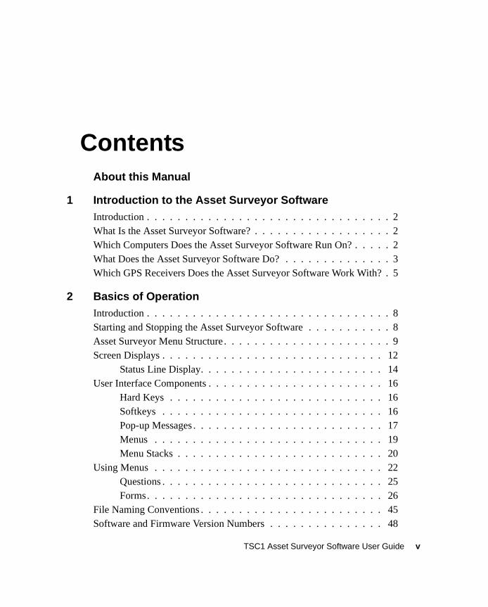
ContentsAbout this Manual
1 Introduction to the Asset Surveyor SoftwareIntroduction . . . . . . . . . . . . . . . . . . . . . . . . . . . . . . . . 2What Is the Asset Surveyor Software? . . . . . . . . . . . . . . . . . . 2Which Computers Does the Asset Surveyor Software Run On? . . . . . 2What Does the Asset Surveyor Software Do? . . . . . . . . . . . . . . 3Which GPS Receivers Does the Asset Surveyor Software Work With? . 5
2 Basics of OperationIntroduction . . . . . . . . . . . . . . . . . . . . . . . . . . . . . . . . 8Starting and Stopping the Asset Surveyor Software . . . . . . . . . . . 8Asset Surveyor Menu Structure . . . . . . . . . . . . . . . . . . . . . . 9Screen Displays . . . . . . . . . . . . . . . . . . . . . . . . . . . . . 12
Status Line Display. . . . . . . . . . . . . . . . . . . . . . . . 14User Interface Components . . . . . . . . . . . . . . . . . . . . . . . 16
Hard Keys . . . . . . . . . . . . . . . . . . . . . . . . . . . . 16Softkeys . . . . . . . . . . . . . . . . . . . . . . . . . . . . . 16Pop-up Messages . . . . . . . . . . . . . . . . . . . . . . . . . 17Menus . . . . . . . . . . . . . . . . . . . . . . . . . . . . . . 19Menu Stacks . . . . . . . . . . . . . . . . . . . . . . . . . . . 20
Using Menus . . . . . . . . . . . . . . . . . . . . . . . . . . . . . . 22Questions . . . . . . . . . . . . . . . . . . . . . . . . . . . . . 25Forms. . . . . . . . . . . . . . . . . . . . . . . . . . . . . . . 26
File Naming Conventions . . . . . . . . . . . . . . . . . . . . . . . . 45Software and Firmware Version Numbers . . . . . . . . . . . . . . . 48
TSC1 Asset Surveyor Software User Guide v
Contents
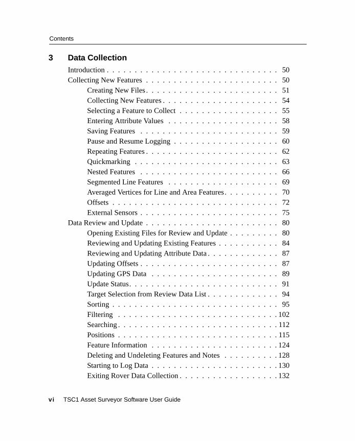
3 Data CollectionIntroduction . . . . . . . . . . . . . . . . . . . . . . . . . . . . . . . 50Collecting New Features . . . . . . . . . . . . . . . . . . . . . . . . 50
Creating New Files . . . . . . . . . . . . . . . . . . . . . . . . 51Collecting New Features . . . . . . . . . . . . . . . . . . . . . 54Selecting a Feature to Collect . . . . . . . . . . . . . . . . . . 55Entering Attribute Values . . . . . . . . . . . . . . . . . . . . 58Saving Features . . . . . . . . . . . . . . . . . . . . . . . . . 59Pause and Resume Logging . . . . . . . . . . . . . . . . . . . 60Repeating Features . . . . . . . . . . . . . . . . . . . . . . . . 62Quickmarking . . . . . . . . . . . . . . . . . . . . . . . . . . 63Nested Features . . . . . . . . . . . . . . . . . . . . . . . . . 66Segmented Line Features . . . . . . . . . . . . . . . . . . . . 69Averaged Vertices for Line and Area Features. . . . . . . . . . 70Offsets . . . . . . . . . . . . . . . . . . . . . . . . . . . . . . 72External Sensors . . . . . . . . . . . . . . . . . . . . . . . . . 75
Data Review and Update . . . . . . . . . . . . . . . . . . . . . . . . 80Opening Existing Files for Review and Update . . . . . . . . . 80Reviewing and Updating Existing Features . . . . . . . . . . . 84Reviewing and Updating Attribute Data . . . . . . . . . . . . . 87Updating Offsets . . . . . . . . . . . . . . . . . . . . . . . . . 87Updating GPS Data . . . . . . . . . . . . . . . . . . . . . . . 89Update Status. . . . . . . . . . . . . . . . . . . . . . . . . . . 91Target Selection from Review Data List . . . . . . . . . . . . . 94Sorting . . . . . . . . . . . . . . . . . . . . . . . . . . . . . . 95Filtering . . . . . . . . . . . . . . . . . . . . . . . . . . . . . 102Searching . . . . . . . . . . . . . . . . . . . . . . . . . . . . . 112Positions . . . . . . . . . . . . . . . . . . . . . . . . . . . . . 115Feature Information . . . . . . . . . . . . . . . . . . . . . . . 124Deleting and Undeleting Features and Notes . . . . . . . . . . 128Starting to Log Data . . . . . . . . . . . . . . . . . . . . . . . 130Exiting Rover Data Collection . . . . . . . . . . . . . . . . . . 132
vi TSC1 Asset Surveyor Software User Guide
Contents
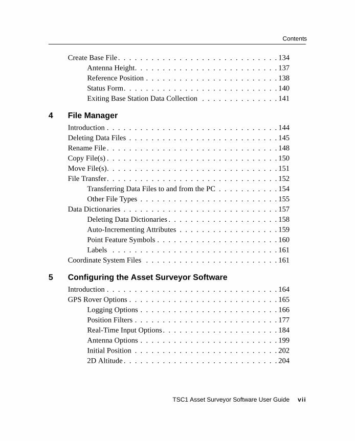
Create Base File . . . . . . . . . . . . . . . . . . . . . . . . . . . . . 134Antenna Height. . . . . . . . . . . . . . . . . . . . . . . . . . 137Reference Position . . . . . . . . . . . . . . . . . . . . . . . . 138Status Form. . . . . . . . . . . . . . . . . . . . . . . . . . . . 140Exiting Base Station Data Collection . . . . . . . . . . . . . . 141
4 File ManagerIntroduction . . . . . . . . . . . . . . . . . . . . . . . . . . . . . . . 144Deleting Data Files . . . . . . . . . . . . . . . . . . . . . . . . . . . 145Rename File . . . . . . . . . . . . . . . . . . . . . . . . . . . . . . . 148Copy File(s) . . . . . . . . . . . . . . . . . . . . . . . . . . . . . . . 150Move File(s). . . . . . . . . . . . . . . . . . . . . . . . . . . . . . . 151File Transfer. . . . . . . . . . . . . . . . . . . . . . . . . . . . . . . 152
Transferring Data Files to and from the PC . . . . . . . . . . . 154Other File Types . . . . . . . . . . . . . . . . . . . . . . . . . 155
Data Dictionaries . . . . . . . . . . . . . . . . . . . . . . . . . . . . 157Deleting Data Dictionaries . . . . . . . . . . . . . . . . . . . . 158Auto-Incrementing Attributes . . . . . . . . . . . . . . . . . . 159Point Feature Symbols . . . . . . . . . . . . . . . . . . . . . . 160Labels . . . . . . . . . . . . . . . . . . . . . . . . . . . . . . 161
Coordinate System Files . . . . . . . . . . . . . . . . . . . . . . . . 161
5 Configuring the Asset Surveyor SoftwareIntroduction . . . . . . . . . . . . . . . . . . . . . . . . . . . . . . . 164GPS Rover Options . . . . . . . . . . . . . . . . . . . . . . . . . . . 165
Logging Options . . . . . . . . . . . . . . . . . . . . . . . . . 166Position Filters . . . . . . . . . . . . . . . . . . . . . . . . . . 177Real-Time Input Options . . . . . . . . . . . . . . . . . . . . . 184Antenna Options . . . . . . . . . . . . . . . . . . . . . . . . . 199Initial Position . . . . . . . . . . . . . . . . . . . . . . . . . . 2022D Altitude . . . . . . . . . . . . . . . . . . . . . . . . . . . . 204
TSC1 Asset Surveyor Software User Guide vii
Contents
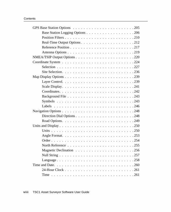
GPS Base Station Options . . . . . . . . . . . . . . . . . . . . . . . 205Base Station Logging Options . . . . . . . . . . . . . . . . . . 206Position Filters . . . . . . . . . . . . . . . . . . . . . . . . . . 210Real-Time Output Options . . . . . . . . . . . . . . . . . . . . 212Reference Position . . . . . . . . . . . . . . . . . . . . . . . . 217Antenna Options . . . . . . . . . . . . . . . . . . . . . . . . . 219
NMEA/TSIP Output Options . . . . . . . . . . . . . . . . . . . . . . 220Coordinate System . . . . . . . . . . . . . . . . . . . . . . . . . . . 224
Selection . . . . . . . . . . . . . . . . . . . . . . . . . . . . . 227Site Selection . . . . . . . . . . . . . . . . . . . . . . . . . . . 236
Map Display Options . . . . . . . . . . . . . . . . . . . . . . . . . . 239Layer Control. . . . . . . . . . . . . . . . . . . . . . . . . . . 239Scale Display . . . . . . . . . . . . . . . . . . . . . . . . . . . 241Coordinates. . . . . . . . . . . . . . . . . . . . . . . . . . . . 242Background File . . . . . . . . . . . . . . . . . . . . . . . . . 243Symbols . . . . . . . . . . . . . . . . . . . . . . . . . . . . . 243Labels . . . . . . . . . . . . . . . . . . . . . . . . . . . . . . 246
Navigation Options . . . . . . . . . . . . . . . . . . . . . . . . . . . 248Direction Dial Options . . . . . . . . . . . . . . . . . . . . . . 248Road Options . . . . . . . . . . . . . . . . . . . . . . . . . . . 249
Units and Display . . . . . . . . . . . . . . . . . . . . . . . . . . . . 250Units . . . . . . . . . . . . . . . . . . . . . . . . . . . . . . . 250Angle Format. . . . . . . . . . . . . . . . . . . . . . . . . . . 253Order . . . . . . . . . . . . . . . . . . . . . . . . . . . . . . . 254North Reference . . . . . . . . . . . . . . . . . . . . . . . . . 255Magnetic Declination . . . . . . . . . . . . . . . . . . . . . . 256Null String . . . . . . . . . . . . . . . . . . . . . . . . . . . . 257Language . . . . . . . . . . . . . . . . . . . . . . . . . . . . . 258
Time and Date. . . . . . . . . . . . . . . . . . . . . . . . . . . . . . 26024-Hour Clock . . . . . . . . . . . . . . . . . . . . . . . . . . 261Time . . . . . . . . . . . . . . . . . . . . . . . . . . . . . . . 261
vi i i TSC1 Asset Surveyor Software User Guide
Contents
Date Format . . . . . . . . . . . . . . . . . . . . . . . . . . . 262Date. . . . . . . . . . . . . . . . . . . . . . . . . . . . . . . . 262
Quickmarks . . . . . . . . . . . . . . . . . . . . . . . . . . . . . . . 263Attributes . . . . . . . . . . . . . . . . . . . . . . . . . . . . . 263Confirm. . . . . . . . . . . . . . . . . . . . . . . . . . . . . . 264
Constant Offset . . . . . . . . . . . . . . . . . . . . . . . . . . . . . 264Point Features . . . . . . . . . . . . . . . . . . . . . . . . . . 265Quickmarks, Lines, and Areas . . . . . . . . . . . . . . . . . . 267
External Sensors . . . . . . . . . . . . . . . . . . . . . . . . . . . . 269Configuring an External Sensor . . . . . . . . . . . . . . . . . 270Activating an External Sensor . . . . . . . . . . . . . . . . . . 282Testing an External Sensor . . . . . . . . . . . . . . . . . . . . 284Configuring a Laser Rangefinder . . . . . . . . . . . . . . . . 289Activating the Laser Rangefinder . . . . . . . . . . . . . . . . 290Testing the Laser Rangefinder Interface . . . . . . . . . . . . . 292
TSC1 Hardware . . . . . . . . . . . . . . . . . . . . . . . . . . . . . 293LCD Contrast. . . . . . . . . . . . . . . . . . . . . . . . . . . 293Backlight . . . . . . . . . . . . . . . . . . . . . . . . . . . . . 294Low Voltage Charging . . . . . . . . . . . . . . . . . . . . . . 294Auto Shutoff . . . . . . . . . . . . . . . . . . . . . . . . . . . 294Beep Volume . . . . . . . . . . . . . . . . . . . . . . . . . . . 295Free Space . . . . . . . . . . . . . . . . . . . . . . . . . . . . 295PC Card Free Space . . . . . . . . . . . . . . . . . . . . . . . 295Battery Fields. . . . . . . . . . . . . . . . . . . . . . . . . . . 296Automatic Contrast. . . . . . . . . . . . . . . . . . . . . . . . 297Software Version . . . . . . . . . . . . . . . . . . . . . . . . . 297Licenses . . . . . . . . . . . . . . . . . . . . . . . . . . . . . 297
TSC1 Asset Surveyor Software User Guide ix
Contents
6 UtilitiesIntroduction . . . . . . . . . . . . . . . . . . . . . . . . . . . . . . . 300Waypoints . . . . . . . . . . . . . . . . . . . . . . . . . . . . . . . . 300
Creating Waypoints . . . . . . . . . . . . . . . . . . . . . . . 302Editing Waypoints . . . . . . . . . . . . . . . . . . . . . . . . 304Deleting Waypoints . . . . . . . . . . . . . . . . . . . . . . . 305Measuring Between Waypoints . . . . . . . . . . . . . . . . . 306
Factory Defaults. . . . . . . . . . . . . . . . . . . . . . . . . . . . . 308Reset GPS Receiver . . . . . . . . . . . . . . . . . . . . . . . . . . . 309Almanac . . . . . . . . . . . . . . . . . . . . . . . . . . . . . . . . . 310Disconnect/Connect GPS . . . . . . . . . . . . . . . . . . . . . . . . 311Entering a Note . . . . . . . . . . . . . . . . . . . . . . . . . . . . . 313
7 NavigationIntroduction . . . . . . . . . . . . . . . . . . . . . . . . . . . . . . . 316Graphical Navigation Modes . . . . . . . . . . . . . . . . . . . . . . 317
Direction Dial Screen . . . . . . . . . . . . . . . . . . . . . . 318Close-up Screen . . . . . . . . . . . . . . . . . . . . . . . . . 319Road Screen . . . . . . . . . . . . . . . . . . . . . . . . . . . 322Navigation Options Form . . . . . . . . . . . . . . . . . . . . 325Map Navigation . . . . . . . . . . . . . . . . . . . . . . . . . 326Old Navigation . . . . . . . . . . . . . . . . . . . . . . . . . . 326Heading Lock . . . . . . . . . . . . . . . . . . . . . . . . . . 326
Text-Based Navigation . . . . . . . . . . . . . . . . . . . . . . . . . 327Distance to Go . . . . . . . . . . . . . . . . . . . . . . . . . . 327Info Panels . . . . . . . . . . . . . . . . . . . . . . . . . . . . 328
Navigation and Waypoints . . . . . . . . . . . . . . . . . . . . . . . 331Selecting the Start and Target . . . . . . . . . . . . . . . . . . 331Navigating to a Target From Your Current Position . . . . . . . 333Navigating from a Start to a Target . . . . . . . . . . . . . . . 336Waypoint Operations . . . . . . . . . . . . . . . . . . . . . . . 337
x TSC1 Asset Surveyor Software User Guide
Contents
8 MapIntroduction . . . . . . . . . . . . . . . . . . . . . . . . . . . . . . . 342Map Display. . . . . . . . . . . . . . . . . . . . . . . . . . . . . . . 342The Map Cursor . . . . . . . . . . . . . . . . . . . . . . . . . . . . . 345
Changing from GPS Cursor to Map Cursor . . . . . . . . . . . 345Selecting Features for Update. . . . . . . . . . . . . . . . . . . . . . 347Zoom Operations . . . . . . . . . . . . . . . . . . . . . . . . . . . . 350Map Display Options . . . . . . . . . . . . . . . . . . . . . . . . . . 351Background File Display . . . . . . . . . . . . . . . . . . . . . . . . 352Text Mode . . . . . . . . . . . . . . . . . . . . . . . . . . . . . . . . 353Filtering . . . . . . . . . . . . . . . . . . . . . . . . . . . . . . . . . 355Navigation in the Map Screen . . . . . . . . . . . . . . . . . . . . . 356
Selecting a Target . . . . . . . . . . . . . . . . . . . . . . . . 356Selecting a Start . . . . . . . . . . . . . . . . . . . . . . . . . 358Navigating to the Target . . . . . . . . . . . . . . . . . . . . . 358Waypoint Operations . . . . . . . . . . . . . . . . . . . . . . . 360
9 Receiver StatusIntroduction . . . . . . . . . . . . . . . . . . . . . . . . . . . . . . . 362Receiver Status Form . . . . . . . . . . . . . . . . . . . . . . . . . . 362
Mode . . . . . . . . . . . . . . . . . . . . . . . . . . . . . . . 362SVs . . . . . . . . . . . . . . . . . . . . . . . . . . . . . . . . 363HDOP and VDOP . . . . . . . . . . . . . . . . . . . . . . . . 363Status . . . . . . . . . . . . . . . . . . . . . . . . . . . . . . . 363Carrier Time . . . . . . . . . . . . . . . . . . . . . . . . . . . 364Battery . . . . . . . . . . . . . . . . . . . . . . . . . . . . . . 364Receiver Type . . . . . . . . . . . . . . . . . . . . . . . . . . 364Navigation Version . . . . . . . . . . . . . . . . . . . . . . . . 365Signal Processor Version . . . . . . . . . . . . . . . . . . . . . 365Landstar ID. . . . . . . . . . . . . . . . . . . . . . . . . . . . 365Omnistar ID . . . . . . . . . . . . . . . . . . . . . . . . . . . 365
DGPS Status . . . . . . . . . . . . . . . . . . . . . . . . . . . . . . 366
TSC1 Asset Surveyor Software User Guide xi
Contents
Detailed Status Information . . . . . . . . . . . . . . . . . . . . . . . 367Service Provider . . . . . . . . . . . . . . . . . . . . . . . . . 368Frequency . . . . . . . . . . . . . . . . . . . . . . . . . . . . 368State . . . . . . . . . . . . . . . . . . . . . . . . . . . . . . . 369SNR . . . . . . . . . . . . . . . . . . . . . . . . . . . . . . . 369Correction Age . . . . . . . . . . . . . . . . . . . . . . . . . . 369DGPS Service Information. . . . . . . . . . . . . . . . . . . . 369User Access . . . . . . . . . . . . . . . . . . . . . . . . . . . 370Decoder State. . . . . . . . . . . . . . . . . . . . . . . . . . . 370Expiration . . . . . . . . . . . . . . . . . . . . . . . . . . . . 371Diagnostic Information. . . . . . . . . . . . . . . . . . . . . . 371Age of Sync . . . . . . . . . . . . . . . . . . . . . . . . . . . 373Station ID. . . . . . . . . . . . . . . . . . . . . . . . . . . . . 373Decoder Version . . . . . . . . . . . . . . . . . . . . . . . . . 373Error Rate . . . . . . . . . . . . . . . . . . . . . . . . . . . . 373Input Level . . . . . . . . . . . . . . . . . . . . . . . . . . . . 374Data Rate . . . . . . . . . . . . . . . . . . . . . . . . . . . . . 374Health . . . . . . . . . . . . . . . . . . . . . . . . . . . . . . 374
10 Satellite InformationIntroduction . . . . . . . . . . . . . . . . . . . . . . . . . . . . . . . 376Text Mode . . . . . . . . . . . . . . . . . . . . . . . . . . . . . . . . 377Graphical Modes . . . . . . . . . . . . . . . . . . . . . . . . . . . . 380
Skyplot Graphical Screen . . . . . . . . . . . . . . . . . . . . 380SNR Levels Screen. . . . . . . . . . . . . . . . . . . . . . . . 382
11 HelpIntroduction . . . . . . . . . . . . . . . . . . . . . . . . . . . . . . . 384Getting Help. . . . . . . . . . . . . . . . . . . . . . . . . . . . . . . 384Getting Help in Different Languages . . . . . . . . . . . . . . . . . . 386Exiting the Help . . . . . . . . . . . . . . . . . . . . . . . . . . . . . 386
xi i TSC1 Asset Surveyor Software User Guide
Contents
A Installing the Asset Surveyor SoftwareIntroduction . . . . . . . . . . . . . . . . . . . . . . . . . . . . . . . 388Equipment Required for Installation . . . . . . . . . . . . . . . . . . 388Installing the Asset Surveyor Version 5.20 Software
on Your TSC1 Datalogger . . . . . . . . . . . . . . . . . . . . 389Loading Options onto the TSC1 Datalogger . . . . . . . . . . . . . . 398
B TroubleshootingIntroduction . . . . . . . . . . . . . . . . . . . . . . . . . . . . . . . 404Troubleshooting . . . . . . . . . . . . . . . . . . . . . . . . . . . . . 404
C Asset Surveyor MessagesIntroduction . . . . . . . . . . . . . . . . . . . . . . . . . . . . . . . 414Messages . . . . . . . . . . . . . . . . . . . . . . . . . . . . . . . . 414
D Asset Surveyor LimitsIntroduction . . . . . . . . . . . . . . . . . . . . . . . . . . . . . . . 456Limits . . . . . . . . . . . . . . . . . . . . . . . . . . . . . . . . . . 456
Index
TSC1 Asset Surveyor Software User Guide xi i i

Contents
xiv TSC1 Asset Surveyor Software User Guide
About this ManualWelcome to the TSC1 Asset Surveyor Software User Guide. Thismanual describes how to operate the Asset Surveyor™ software, inconjunction with a range of Trimble GPS receivers for GIS datacollection and update. The Asset Surveyor software provides all thefunctionality you need to efficiently collect GIS/GPS data.
Even if you have used other Global Positioning System (GPS)products before, we recommend that you spend some time reading thismanual to learn about the special features of this product.
If you are not familiar with GPS, visit our web site for an interactivelook at Trimble and GPS at:
• www.trimble.com
TSC1 Asset Surveyor Software User Guide xv
About this Manual
Related InformationOther manuals in this set include:
• TSC1 Asset Surveyor Operation Manual
This manual describes how to operate the Asset Surveyorsoftware.
• Mapping Systems General Reference
The Mapping Systems General Reference explains general GPSand GIS concepts, as well as the Trimble Survey and MappingBulletin Board.
• GPS Pathfinder Office Documentation
The GPS Pathfinder Office Getting Started Guide contains atutorial chapter that shows you how to use many features thatare common to the GPS Pathfinder® Office software and theAsset Surveyor software.
As well as being supplied in hardcopy, these manuals are alsoavailable in portable document format (PDF). These files are availablefrom the Asset Surveyor installation CD-ROM.
• Readme.txt file – a Readme.txt file contains information addedafter the documentation was completed. To read this file,double-click it or use a text editor to open it.
• Release notes – the release notes describe new features of theproduct, information not included in the manuals, and anychanges to the manuals.
• Update notes – there is a warranty activation sheet with thisproduct. Send it in to automatically receive update notescontaining important information about software and hardwarechanges. Contact your local Trimble Dealer for moreinformation about the support agreement contracts for softwareand firmware, and an extended warranty program for hardware.
xvi TSC1 Asset Surveyor Software User Guide
About this Manual
• ftp.trimble.com – use the Trimble FTP site to send files or toreceive files such as software patches, utilities, servicebulletins, and FAQs. Alternatively, access the FTP site from theTrimble web site at www.trimble.com/support/support.htm.
• Trimble training courses – consider a training course to helpyou use your GPS system to its fullest potential. For moreinformation, visit the Trimble web site atwww.trimble.com/support/training.htm
• RTCM – for information on RTCM SC-104 contact:
Radio Technical Commission for Maritime ServicesP.O. Box 19 087Washington, D.C. 20036U.S.A.
Technical AssistanceIf you have a problem and cannot find the information you need in theproduct documentation, contact your local Distributor. Alternatively,request technical support using the Trimble web site at:
• www.trimble.com/support/support.htm
TSC1 Asset Surveyor Software User Guide xvii
About this Manual
Your CommentsYour feedback about the supporting documentation helps us toimprove it with each revision. To forward your comments, do one ofthe following:
• Send an e-mail to [email protected].
• Complete the Reader Comment Form at the back of this manualand mail it according to the instructions at the bottom of theform.
If the reader comment form is not available, send comments andsuggestions to the address in the front of this manual. Please markthem Attention: Technical Publications Group.
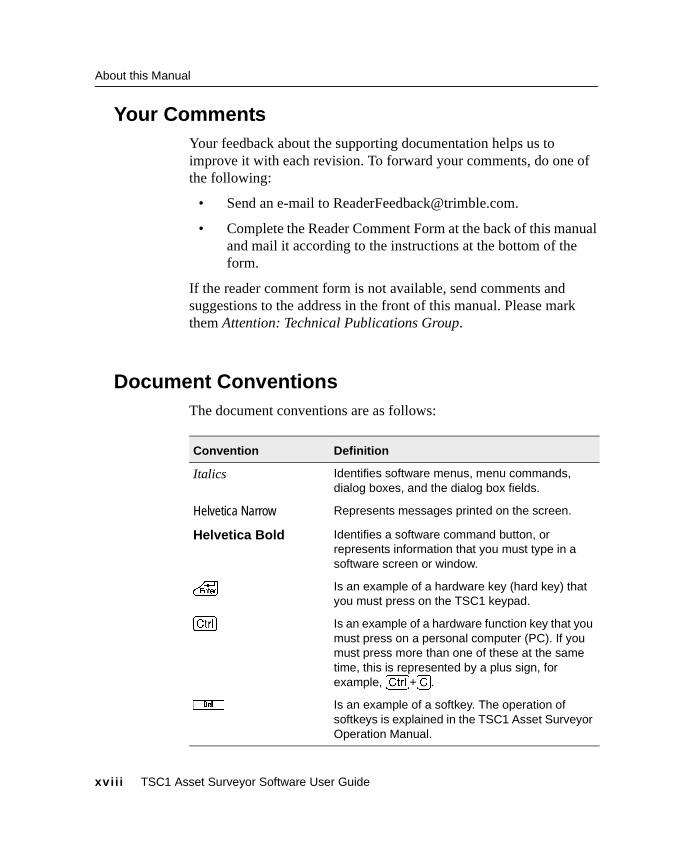
Document ConventionsThe document conventions are as follows:
Convention Definition
Italics Identifies software menus, menu commands,dialog boxes, and the dialog box fields.
Helvetica Narrow Represents messages printed on the screen.
Helvetica Bold Identifies a software command button, orrepresents information that you must type in asoftware screen or window.
\ Is an example of a hardware key (hard key) thatyou must press on the TSC1 keypad.
[Ctrl] Is an example of a hardware function key that youmust press on a personal computer (PC). If youmust press more than one of these at the sametime, this is represented by a plus sign, forexample, [Ctrl]+[C].
d Is an example of a softkey. The operation ofsoftkeys is explained in the TSC1 Asset SurveyorOperation Manual.
xvii i TSC1 Asset Surveyor Software User Guide

C H A P T E R
3C H A P T E R
1
1 Introduction to the AssetSurveyor SoftwareIn this chapter:■ Introduction
■ What Is the Asset Surveyor software?
■ Which computers does the Asset Surveyor software run on?
■ What does the Asset Surveyor Software do?
■ Which GPS receivers does the Asset Surveyor software work with?

1 Introduction to the Asset Surveyor Software
1.1 IntroductionCongratulations on purchasing the Trimble Asset Surveyor™GIS/GPS data collection system. The combination of sophisticateddata collection software and GPS positioning hardware enables you toefficiently collect and update high quality GIS data.
1.2 What Is the Asset Surveyor Software?The Asset Surveyor software is a computer program produced byTrimble Navigation Limited for a wide range of GeographicInformation System (GIS) data collection and data updateapplications.
The Asset Surveyor software works with a range of GlobalPositioning System (GPS) receivers produced by Trimble NavigationLimited.
1.3 Which Computers Does the Asset SurveyorSoftware Run On?
The Asset Surveyor software runs on the Trimble TSC1™ datalogger.The TSC1 datalogger is an extremely rugged, lightweight, andwaterproof handheld computer. The TSC1 datalogger can be used forGIS data collection applications in the most hostile environments. TheTSC1 datalogger also runs the Trimble Survey Controller™ software,and a single TSC1 datalogger can be shared between GIS and LandSurvey applications. The TSC1 datalogger has 2MB of memory forcollected data, as well as a PC card slot where data storage cards canbe used for extended memory storage.
2 TSC1 Asset Surveyor Software User Guide
Introduction to the Asset Surveyor Software 1
1.4 What Does the Asset Surveyor Software Do?The primary function of the Asset Surveyor software is the automatedcollection and/or update of information related to geographic features.Together with a Trimble GPS receiver, the Asset Surveyor softwarecan quickly and accurately collect or update the attributes and GPSposition of geographic points, lines, and areas. This information isstored in one or more data files, which you can load into the TrimbleGPS Pathfinder® Office software suite. After postprocessing andediting, data can then be output in a wide range of GIS-compatibleformats.
Applications for the Asset Surveyor software include forestrymapping, environmental and resource management, disasterassessment, utility inventories, and urban asset management. Forexample, a power company could build an asset register of all itspower poles, record their positions (to within a meter), their conditionand structure, and any attached hardware. A maintenance crew maylater use the software’s navigation functions to locate poles requiringrepair. You can also use the data maintenance capability of the AssetSurveyor software to update the position and attribute information forfeatures in the field to ensure that your GIS database is accurate andup to date.
You can review, edit, or delete data in the field so that the data that youcollect and take back to the office is correct and complete.
The Asset Surveyor software provides convenient and powerfulcontrol of your Trimble GPS receiver, enabling you to take fulladvantage of the potential that GPS offers.
The Asset Surveyor software lets you collect carrier phase data forpoints, lines, and areas to compute positions to decimeter accuracywith version 2.00 or later of the GPS Pathfinder Office software. TheAsset Surveyor software, when used with a GPS Pathfinder Pro XR™or a Pro XRS™ receiver, can also collect data to recorrect real-timedifferential data collected in the field, for even greater accuracy.
TSC1 Asset Surveyor Software User Guide 3
1 Introduction to the Asset Surveyor Software
You can operate the Asset Surveyor software as a temporary GPS basestation in situations where it is impossible or impractical to set up apermanent base station. The Asset Surveyor software, in combinationwith one of the GPS Pathfinder Pro XL™, Pro XR, or Pro XRS, GPSTotal Station 4700™, GPS Total Station 4800™, Series 4000™ or SiteSurveyor 4400™ GPS receivers, can output RTCM messages whenoperating as a base station. These messages can be received by anumber of GPS Pathfinder receivers with a suitable radio link.
The Asset Surveyor software can be used in conjunction with an RTKreceiver for Real-time Kinematic (RTK) data collection.
The Asset Surveyor software lets you use your Trimble GPS receiverfor navigation to a waypoint or to a previously recorded geographicfeature.
The Asset Surveyor software provides integrated support for a numberof laser rangefinders used to record offsets to geographical features.The use of offsets makes it possible to collect data in circumstanceswhere the use of GPS alone might be inconvenient or even impossible.
The Asset Surveyor software can collect data from a wide range ofexternal sensors equipped with an RS232 port. Each reading from theexternal sensor can be stored as an attribute of a feature, or have a GPSposition associated with it. This lets you correlate information frominstruments such as depth sounders, Geiger counters, and tree calipers,with GPS positions.
The Asset Surveyor software has been translated into a number oflanguages. For each supported language (French, German,Portuguese, Russian and Spanish) all text displayed by Asset Surveyorappears in that language, instead of English.
4 TSC1 Asset Surveyor Software User Guide
Introduction to the Asset Surveyor Software 1
1.5 Which GPS Receivers Does the Asset SurveyorSoftware Work With?
The TSC1 Asset Surveyor software works with the following TrimbleGPS receivers:
• the GPS Pathfinder receiver family, which includes the GPSPathfinder Pro XRS, the GPS Pathfinder Pro XR, and the GPSPathfinder Pro XL
• GPS Total Station 4700
• GPS Total Station 4800
• Site Surveyor 4400
• 4600LS Surveyor
• the Series 4000 GPS receiver family, which includes the4000SE™, 4000SSE™, and the 4000SSi™
TSC1 Asset Surveyor Software User Guide 5

1 Introduction to the Asset Surveyor Software
6 TSC1 Asset Surveyor Software User Guide

C H A P T E R
3C H A P T E R
2
2 Basics of OperationIn this chapter:
■ Introduction
■ Starting and stopping the Asset Surveyor software
■ Asset Surveyor menu structure
■ Screen displays
■ User interface components
■ Using menus
■ File naming conventions
■ Software and firmware version numbers
2 Basics of Operation
2.1 IntroductionThis chapter describes how to use the Asset Surveyor software usingthe TSC1 datalogger as a platform. It provides a description of AssetSurveyor user interface and data entry concepts.
The Asset Surveyor software makes GIS data collection and update afaster and more efficient process. The best way to learn how to use theAsset Surveyor software in conjunction with the TSC1 datalogger is totake it out into the field and practise.
2.2 Starting and Stopping the Asset Surveyor SoftwareYou generally do not have to stop the Asset Surveyor software as youcan just turn off the TSC1 datalogger when you have finished using itand turn it on again when you next want to use it.
When you turn the TSC1 datalogger on (by pressing|), the AssetSurveyor software starts and the Main menu appears.
You can restart the Asset Surveyor software by rebooting your TSC1datalogger. This should rarely be necessary.
When you have finished using the Asset Surveyor software, press the| key to stop the Asset Surveyor software and turn off the TSC1datalogger.
If you turn the TSC1 datalogger off while a file is open or the AssetSurveyor software is logging data to a file, the Asset Surveyorsoftware closes the file before shutting down.
C Warning – Trimble recommends that you do not turn off the TSC1datalogger while upgrading software, or while transferring files betweenthe datalogger and the PC or PC card. Otherwise your data or system filesmay be corrupted.
8 TSC1 Asset Surveyor Software User Guide
Basics of Operation 2
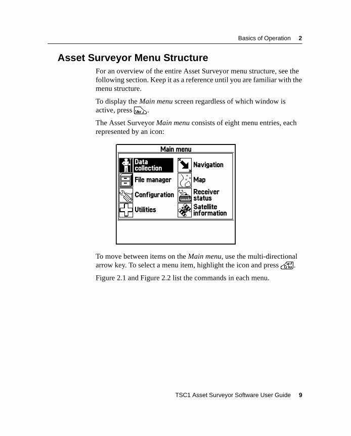
2.3 Asset Surveyor Menu StructureFor an overview of the entire Asset Surveyor menu structure, see thefollowing section. Keep it as a reference until you are familiar with themenu structure.
To display the Main menu screen regardless of which window isactive, pressM .
The Asset Surveyor Main menu consists of eight menu entries, eachrepresented by an icon:
To move between items on the Main menu, use the multi-directionalarrow key. To select a menu item, highlight the icon and press\ .
Figure 2.1 and Figure 2.2 list the commands in each menu.
TSC1 Asset Surveyor Software User Guide 9
2 Basics of Operation
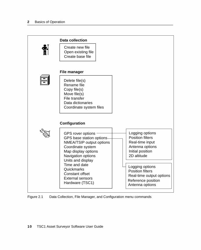
Figure 2.1 Data Collection, File Manager, and Configuration menu commands
Data collection
Create new fileOpen existing fileCreate base file
File manager
Configuration
Delete file(s)Rename fileCopy file(s)Move file(s)File transferData dictionariesCoordinate system files
Logging optionsPosition filters
Antenna optionsInitial position2D altitude
Logging optionsPosition filters
Antenna options
Real-time output options
GPS rover optionsGPS base station optionsNMEA/TSIP output optionsCoordinate systemMap display optionsNavigation optionsUnits and displayTime and dateQuickmarksConstant offsetExternal sensorsHardware (TSC1)
Real-time input
Reference position
10 TSC1 Asset Surveyor Software User Guide

Basics of Operation 2
Figure 2.2 Utilities, Navigation, Map, Receiver Status, and Satellite Information menucommands
Utilities
Navigation (Press@ to switch modes)
WaypointsFactory defaultsReset GPS receiverAlmanacDisconnect GPSNote
Map (Press@ to switch modes)
MapText mode
Receiver status
GPSDGPS
Satellite information (Press@ to switch modes)
Text modeSkyplotSNR levels
Direction dialRoad
TSC1 Asset Surveyor Software User Guide 11
2 Basics of Operation
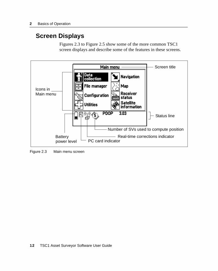
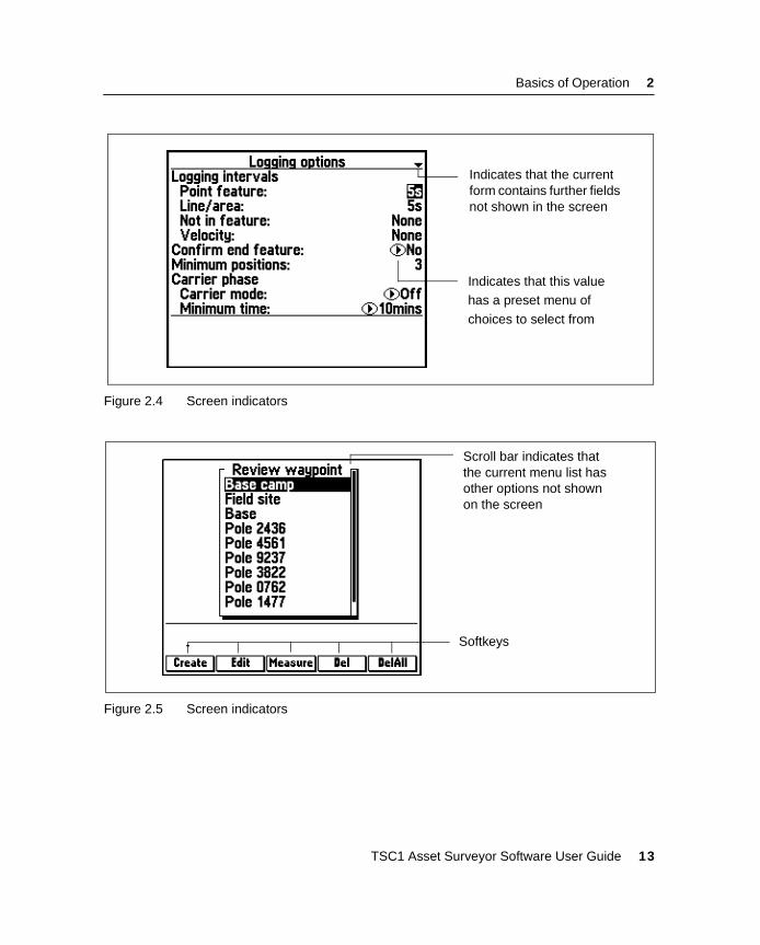
2.4 Screen DisplaysFigures 2.3 to Figure 2.5 show some of the more common TSC1screen displays and describe some of the features in these screens.
Figure 2.3 Main menu screen
Screen title
Icons in
Number of SVs used to compute position
Status line
BatteryPC card indicator
Real-time corrections indicatorpower level
Main menu
12 TSC1 Asset Surveyor Software User Guide
Basics of Operation 2
Figure 2.4 Screen indicators
Figure 2.5 Screen indicators
Indicates that the currentform contains further fieldsnot shown in the screen
Indicates that this valuehas a preset menu of
choices to select from
Scroll bar indicates thatthe current menu list hasother options not shownon the screen
Softkeys
TSC1 Asset Surveyor Software User Guide 13
2 Basics of Operation
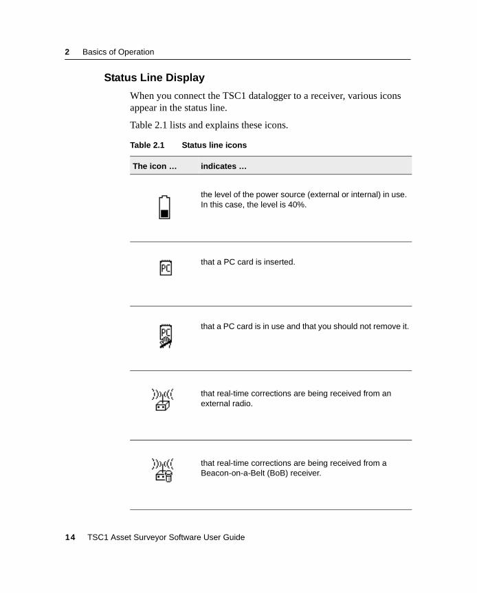
2.4.1 Status Line Display
When you connect the TSC1 datalogger to a receiver, various iconsappear in the status line.
Table 2.1 lists and explains these icons.
Table 2.1 Status line icons
The icon … indicates …
the level of the power source (external or internal) in use.In this case, the level is 40%.
that a PC card is inserted.
that a PC card is in use and that you should not remove it.
that real-time corrections are being received from anexternal radio.
that real-time corrections are being received from aBeacon-on-a-Belt (BoB) receiver.
14 TSC1 Asset Surveyor Software User Guide
Basics of Operation 2
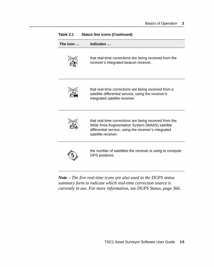
Note – The five real-time icons are also used in the DGPS statussummary form to indicate which real-time correction source iscurrently in use. For more information, see DGPS Status, page 366.
that real-time corrections are being received from thereceiver’s integrated beacon receiver.
that real-time corrections are being received from asatellite differential service, using the receiver’sintegrated satellite receiver.
that real-time corrections are being received from theWide Area Augmentation System (WAAS) satellitedifferential service, using the receiver’s integratedsatellite receiver.
the number of satellites the receiver is using to computeGPS positions.
Table 2.1 Status line icons (Continued)
The icon … indicates …
TSC1 Asset Surveyor Software User Guide 15
2 Basics of Operation
2.5 User Interface ComponentsYou can interact with the Asset Surveyor software in a variety ofways, each of which is described below.
2.5.1 Hard Keys
These are the physical keys on the TSC1 keypad. They includealphabetic and numeric keys as well as special-purpose keys such as\ orS .
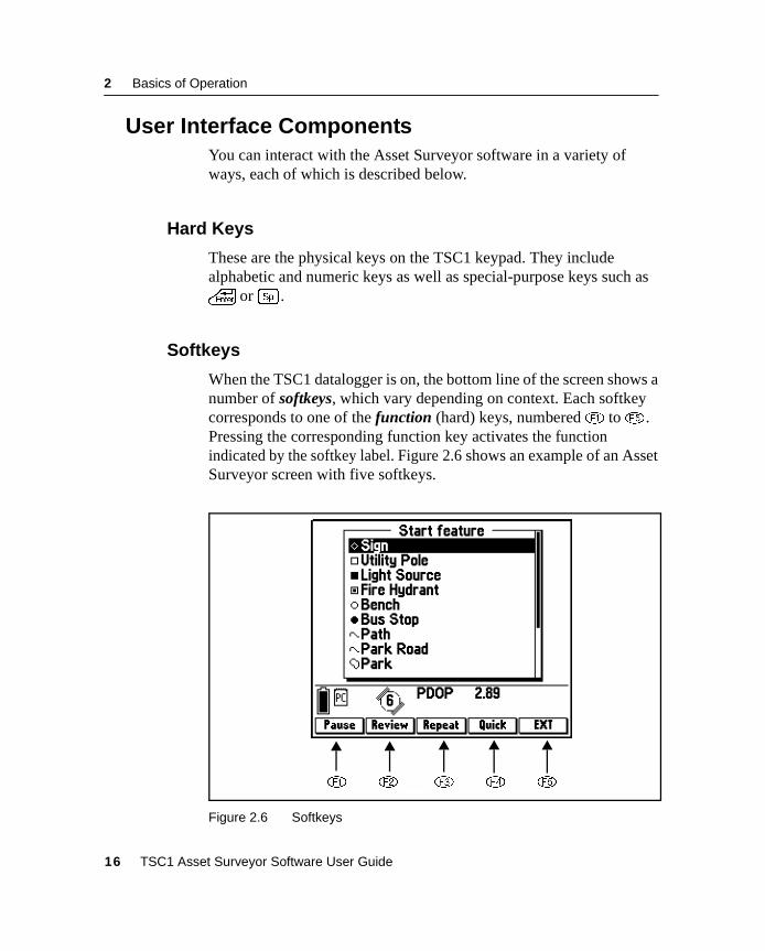
2.5.2 Softkeys
When the TSC1 datalogger is on, the bottom line of the screen shows anumber of softkeys, which vary depending on context. Each softkeycorresponds to one of the function (hard) keys, numbered! to% .Pressing the corresponding function key activates the functionindicated by the softkey label. Figure 2.6 shows an example of an AssetSurveyor screen with five softkeys.
Figure 2.6 Softkeys
! @ # $ %
16 TSC1 Asset Surveyor Software User Guide
Basics of Operation 2
For example, press! to activate thep function, and@ toactivate the{ function.
Occasionally, there are too many softkeys on a particular form ormenu to fit on the screen. When this happens, the fifth softkey appearsas> . You can press> to step from one ‘page’ of softkeys tothe next. Press the softkey you require when its ‘page’ appears. Whenthere are fewer than five softkeys, the remaining function key(s)perform no action.
2.5.3 Pop-up Messages
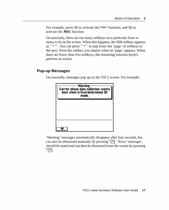
Occasionally, messages pop up on the TSC1 screen. For example:
‘Warning’ messages automatically disappear after four seconds, butcan also be dismissed manually by pressing= . ‘Error’ messagesshould be noted and can then be dismissed from the screen by pressing= .
TSC1 Asset Surveyor Software User Guide 17
2 Basics of Operation
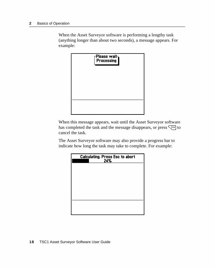
When the Asset Surveyor software is performing a lengthy task(anything longer than about two seconds), a message appears. Forexample:
When this message appears, wait until the Asset Surveyor softwarehas completed the task and the message disappears, or press= tocancel the task.
The Asset Surveyor software may also provide a progress bar toindicate how long the task may take to complete. For example:
18 TSC1 Asset Surveyor Software User Guide
Basics of Operation 2
If you do not want to wait for the Asset Surveyor software to completethe task, you can cancel the task by pressing= . There are a fewcritical tasks which cannot be cancelled. If the software is performinga critical task and you press= to cancel it, the Asset Surveyorsoftware simply beeps and continues with the task.
2.5.4 Menus
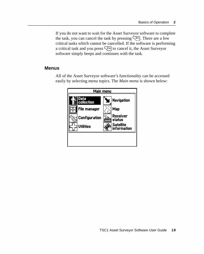
All of the Asset Surveyor software’s functionality can be accessedeasily by selecting menu topics. The Main menu is shown below:
TSC1 Asset Surveyor Software User Guide 19
2 Basics of Operation
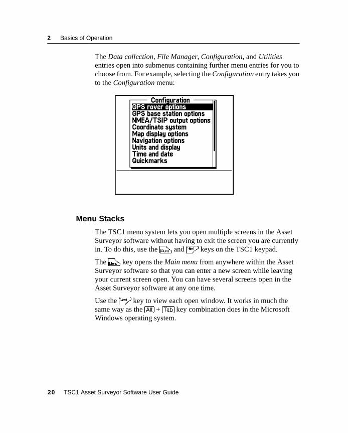
The Data collection, File Manager, Configuration, and Utilitiesentries open into submenus containing further menu entries for you tochoose from. For example, selecting the Configuration entry takes youto the Configuration menu:
2.5.5 Menu Stacks
The TSC1 menu system lets you open multiple screens in the AssetSurveyor software without having to exit the screen you are currentlyin. To do this, use theM andN keys on the TSC1 keypad.
TheM key opens the Main menu from anywhere within the AssetSurveyor software so that you can enter a new screen while leavingyour current screen open. You can have several screens open in theAsset Surveyor software at any one time.
Use theN key to view each open window. It works in much thesame way as the [Alt] + [Tab] key combination does in the MicrosoftWindows operating system.
20 TSC1 Asset Surveyor Software User Guide
Basics of Operation 2
For example, from the Main menu select File manager / Delete file(s).Now pressM to return to the Main menu and select Satelliteinformation. PressM again to return to the Main menu and selectConfiguration / Hardware. There are now three windows (Deletefile(s), Satellite information, and Hardware) open at the same time. Bypressing theN key successively, you can quickly view all of thescreens open in a menu stack. To remove a window from this stack,simply view the window (by pressingN until the window appears)and press= to return to the Main menu.
Only one screen from each Main menu entry may be open in thewindow stack at any one time. If you select an entry from the Mainmenu that already has a screen open in the stack, the Asset Surveyorsoftware takes you directly to the open screen and you are not be ableto open another screen within that menu until you exit the open screen.For example, if the Configuration / GPS rover options / Loggingoptions form is open in the stack, selecting Configuration from theMain menu takes you directly to the open Logging options form. Youcannot open another screen within Configuration (for example, Unitsand Display) until you exit out of GPS rover options.
TSC1 Asset Surveyor Software User Guide 21
2 Basics of Operation
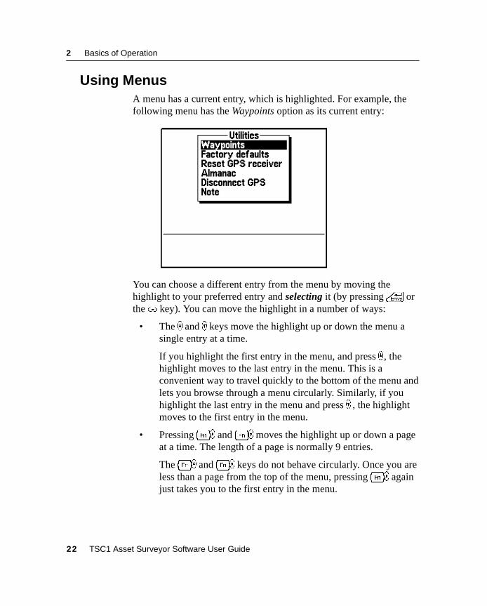
2.6 Using MenusA menu has a current entry, which is highlighted. For example, thefollowing menu has the Waypoints option as its current entry:
You can choose a different entry from the menu by moving thehighlight to your preferred entry and selecting it (by pressing\ orthe( key). You can move the highlight in a number of ways:
• The _ and ) keys move the highlight up or down the menu asingle entry at a time.
If you highlight the first entry in the menu, and press _ , thehighlight moves to the last entry in the menu. This is aconvenient way to travel quickly to the bottom of the menu andlets you browse through a menu circularly. Similarly, if youhighlight the last entry in the menu and press ) , the highlightmoves to the first entry in the menu.
• Pressing[_ and[) moves the highlight up or down a pageat a time. The length of a page is normally 9 entries.
The[_ and[) keys do not behave circularly. Once you areless than a page from the top of the menu, pressing[_ againjust takes you to the first entry in the menu.
22 TSC1 Asset Surveyor Software User Guide
Basics of Operation 2
• Pressing[* and[( moves the highlight to the first andlast entries in the menu, respectively.
• Pressing an alphanumeric key corresponding to the first letter ofa menu entry moves the highlight directly to that entry. If thereis more than one entry in the menu starting with that letter,pressing that alphanumeric key repeatedly steps through theentries beginning with that letter. If you highlight a menu entryby typing the first letter of its name, and it is the only entry inthe menu which starts with that letter, the entry is selectedautomatically.
B Tip – This “first-letter” method is often the fastest way of selecting an entryfrom a menu.
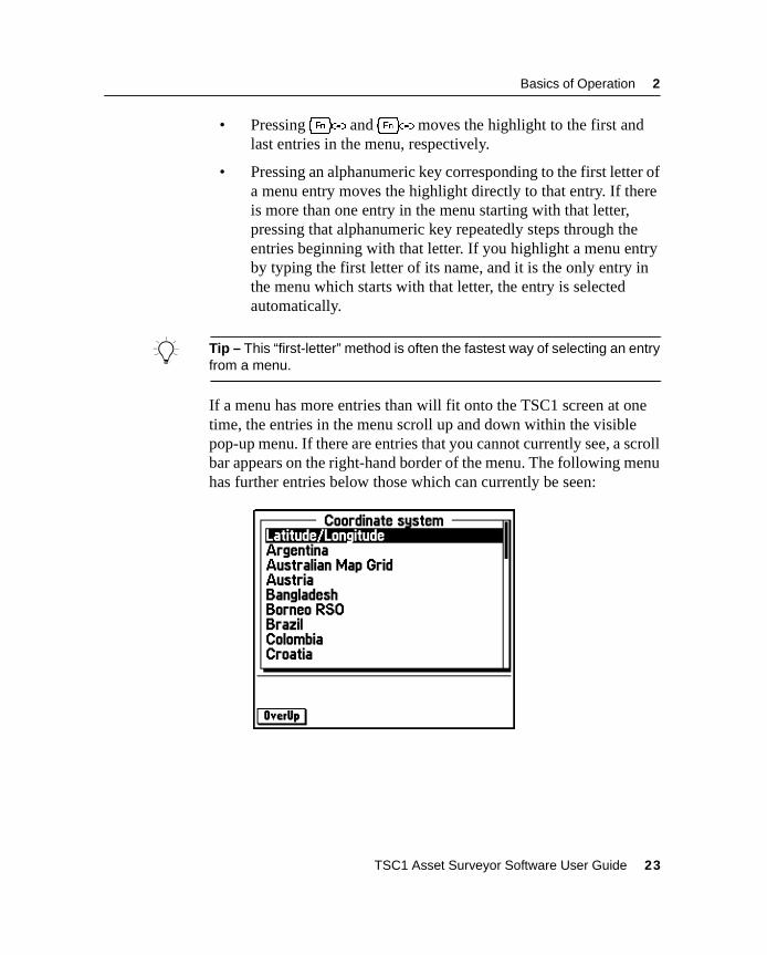
If a menu has more entries than will fit onto the TSC1 screen at onetime, the entries in the menu scroll up and down within the visiblepop-up menu. If there are entries that you cannot currently see, a scrollbar appears on the right-hand border of the menu. The following menuhas further entries below those which can currently be seen:
TSC1 Asset Surveyor Software User Guide 23
2 Basics of Operation
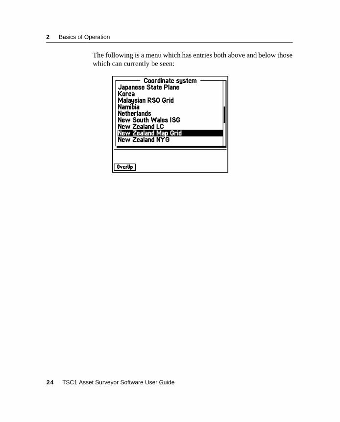
The following is a menu which has entries both above and below thosewhich can currently be seen:
24 TSC1 Asset Surveyor Software User Guide
Basics of Operation 2
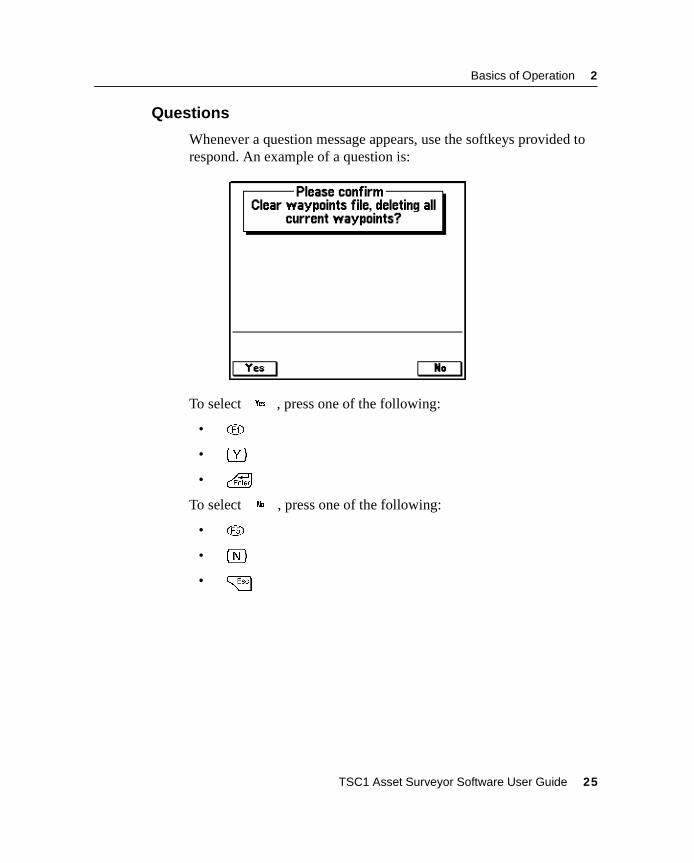
2.6.1 Questions
Whenever a question message appears, use the softkeys provided torespond. An example of a question is:
To selecty, press one of the following:
• !
• y
• \
To selectn , press one of the following:
• %
• n
• =
TSC1 Asset Surveyor Software User Guide 25
2 Basics of Operation
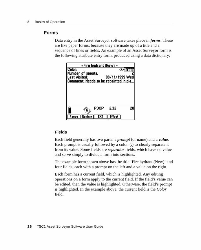
2.6.2 Forms
Data entry in the Asset Surveyor software takes place in forms. Theseare like paper forms, because they are made up of a title and asequence of lines or fields. An example of an Asset Surveyor form isthe following attribute entry form, produced using a data dictionary:
Fields
Each field generally has two parts: a prompt (or name) and a value.Each prompt is usually followed by a colon (:) to clearly separate itfrom its value. Some fields are separator fields, which have no valueand serve simply to divide a form into sections.
The example form shown above has the title ‘Fire hydrant (New)’ andfour fields, each with a prompt on the left and a value on the right.
Each form has a current field, which is highlighted. Any editingoperations on a form apply to the current field. If the field’s value canbe edited, then the value is highlighted. Otherwise, the field’s promptis highlighted. In the example above, the current field is the Colorfield.
26 TSC1 Asset Surveyor Software User Guide
Basics of Operation 2
If a field’s value cannot be shown in full due to the limited width ofthe TSC1 screen, ellipses (…) indicate that not all of the field’s valueis visible. For example, the full value of the Comments field in theexample above is ‘Needs to be repainted in places’.
Note – There is a special field value, called the null value, whichdenotes no value at all. This is often supplied as the default value for afield, to ensure that you enter a real value. The null value is usuallydisplayed as a ‘?’ character, but the Asset Surveyor software lets youconfigure the null value if you want.
B Tip – You can choose the default value for each attribute, and whetherdata entry is required or prohibited, when you create a data dictionary. Formore information, see the GPS Pathfinder Office Help.
TSC1 Asset Surveyor Software User Guide 27
2 Basics of Operation
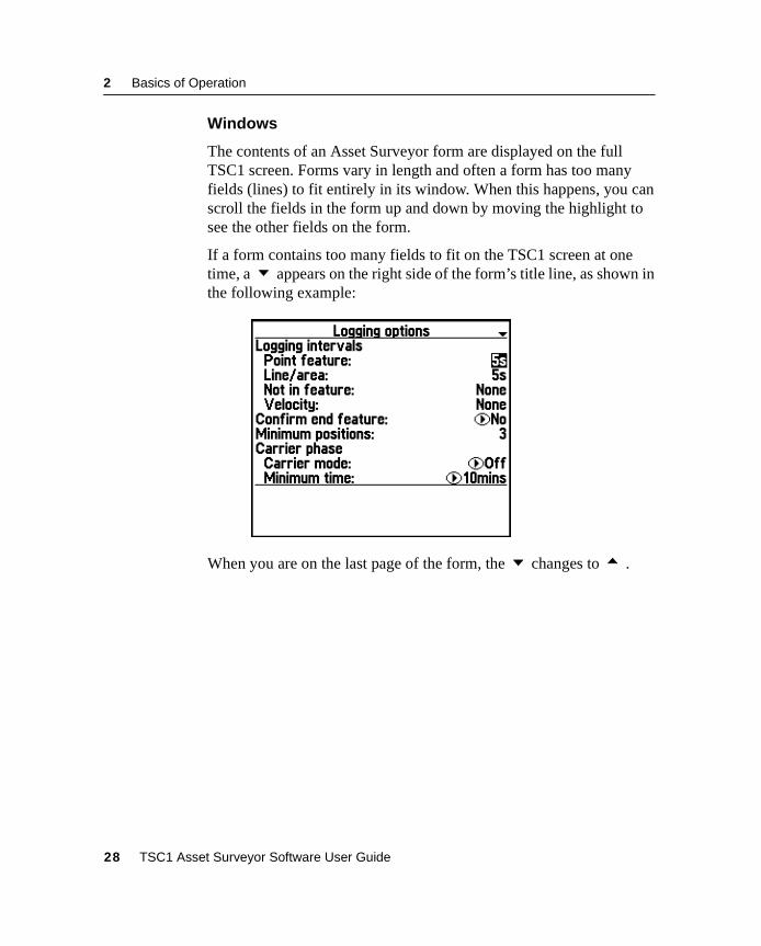
Windows
The contents of an Asset Surveyor form are displayed on the fullTSC1 screen. Forms vary in length and often a form has too manyfields (lines) to fit entirely in its window. When this happens, you canscroll the fields in the form up and down by moving the highlight tosee the other fields on the form.
If a form contains too many fields to fit on the TSC1 screen at onetime, a appears on the right side of the form’s title line, as shown inthe following example:
When you are on the last page of the form, the changes to .
28 TSC1 Asset Surveyor Software User Guide
Basics of Operation 2
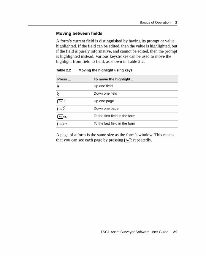
Moving between fields
A form’s current field is distinguished by having its prompt or valuehighlighted. If the field can be edited, then the value is highlighted, butif the field is purely informative, and cannot be edited, then the promptis highlighted instead. Various keystrokes can be used to move thehighlight from field to field, as shown in Table 2.2.
A page of a form is the same size as the form’s window. This meansthat you can see each page by pressing[) repeatedly.
Table 2.2 Moving the highlight using keys
Press ... To move the highlight ...
_ Up one field
) Down one field
[_ Up one page
[) Down one page
[* To the first field in the form
[( To the last field in the form
TSC1 Asset Surveyor Software User Guide 29
2 Basics of Operation
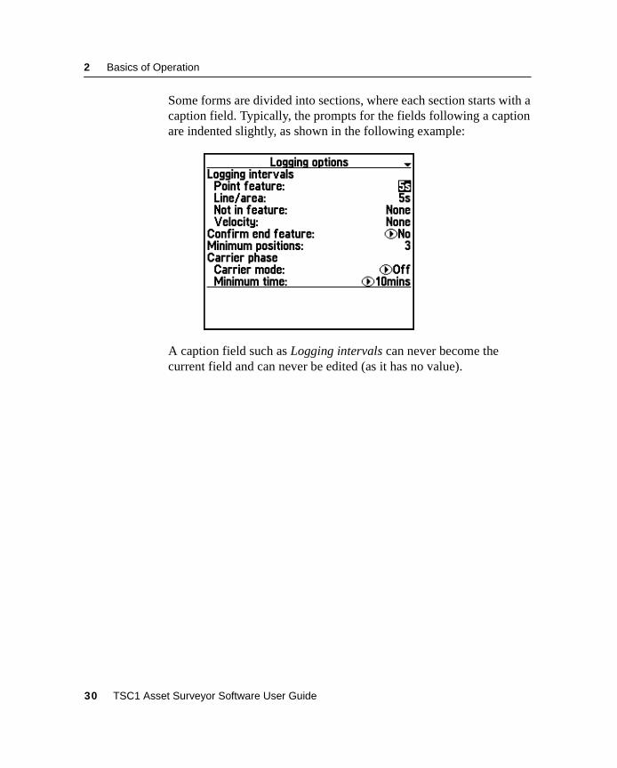
Some forms are divided into sections, where each section starts with acaption field. Typically, the prompts for the fields following a captionare indented slightly, as shown in the following example:
A caption field such as Logging intervals can never become thecurrent field and can never be edited (as it has no value).
30 TSC1 Asset Surveyor Software User Guide
Basics of Operation 2
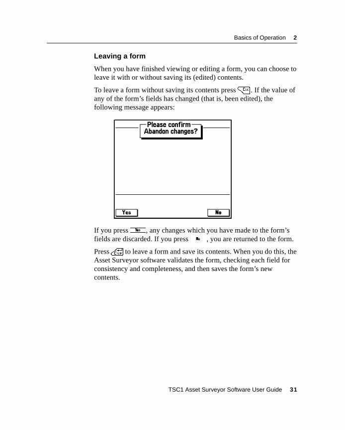
Leaving a form
When you have finished viewing or editing a form, you can choose toleave it with or without saving its (edited) contents.
To leave a form without saving its contents press= . If the value ofany of the form’s fields has changed (that is, been edited), thefollowing message appears:
If you pressy, any changes which you have made to the form’sfields are discarded. If you pressn , you are returned to the form.
Press\ to leave a form and save its contents. When you do this, theAsset Surveyor software validates the form, checking each field forconsistency and completeness, and then saves the form’s newcontents.
TSC1 Asset Surveyor Software User Guide 31
2 Basics of Operation
Editing fields
Generally, each field’s value can be changed or edited. Before you canchange the value of a particular field, you must move the highlight tothat field.
The two ways to change the value of the current field are:
• Type the complete new value into the field: Once you havehighlighted the appropriate field’s value, you can just type inthe new value. This replaces the field’s old value.
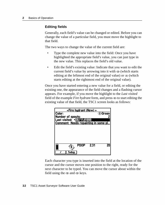
• Edit the field’s existing value: Indicate that you want to edit thecurrent field’s value by arrowing into it with( (which startsediting at the leftmost end of the original value) or* (whichstarts editing at the rightmost end of the original value).
Once you have started entering a new value for a field, or editing theexisting one, the appearance of the field changes and a flashing cursorappears. For example, if you move the highlight to the Last visitedfield of the example Fire hydrant form, and press( to start editing theexisting value of that field, the TSC1 screen looks as follows:
Each character you type is inserted into the field at the location of thecursor and the cursor moves one position to the right, ready for thenext character to be typed. You can move the cursor about within thefield using the* and( keys.
32 TSC1 Asset Surveyor Software User Guide
Basics of Operation 2
You can delete the character to the left of the cursor, and move thecursor one character to the left in the process, by pressingB . Youcan delete the character that is to the right of the cursor (for example,the ‘1’ in ‘1999’ in the example above) by pressing[B .
Insert and overwrite modes
The Asset Surveyor software operates in Insert mode, where eachcharacter you type is inserted at the cursor position and pushes thecurrent character in that position to the right, after which the cursormoves one position to the right as well. The Asset Surveyor softwaredoes not operate in Overwrite mode (where each character you typeoverwrites the current character at that position).
Upper and lower case letters
PressC to change between upper and lower case letters. When youpress theC key it changes modes, rather than just modifyingcharacters typed while it is held down. TheC key operates like the[CapsLock] key on a PC.
Leaving field entry
If you start to edit a field but do not want to continue, press= torevert back to the field’s previous value.
When you are satisfied with the field’s edited value, you can do one ofthe following:
• Press _ to move to the previous field in the form.
• Press ) to move to the next field in the form.
• Press\ to move to the next field in the form.
TSC1 Asset Surveyor Software User Guide 33
2 Basics of Operation
Before moving to another field, the Asset Surveyor software validatesthe new value for the field which you have just changed. If the field’snew value is inappropriate, you are informed of this fact and asked tochange it. The Asset Surveyor software does not accept aninappropriate value for a field.
Certain fields behave in special ways when being edited, and havespecial validation rules, as explained in the following section.
Field types
Each field belongs to a particular type or class, and the type of thefield determines the kind of value it can have. The types of fieldsupported by the Asset Surveyor software are:
• Captions or separators, which have no value. You cannot editthese fields.
• Alphanumeric character string fields, which permit the entry ofany characters (that is, letters, digits and punctuationcharacters), up to a certain maximum length. An example of analphanumeric string is the comment ‘Requires pruning of thelower branches’.
• Numeric fields, which let you enter numbers, with or withoutattached units. An example of a numeric value is ‘3.4’.
• Menu fields, which let you select one of a small set of specificvalues. For example, a menu field might let you choose betweenvalues of ‘Yes’, ‘No’ and ‘Maybe’.
• Date fields, which permit the entry of a calendar date. Anexample of a date value is ‘09/03/99 Fri’.
• Time fields, which permit the entry of a time of day. Anexample of a time value is ‘10:44:12 am’.
The following sections discuss each of the Asset Surveyor field typesin more detail.
34 TSC1 Asset Surveyor Software User Guide
Basics of Operation 2
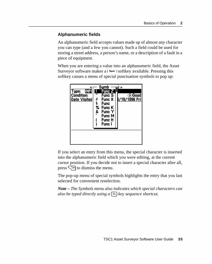
Alphanumeric fields
An alphanumeric field accepts values made up of almost any characteryou can type (and a few you cannot). Such a field could be used forstoring a street address, a person’s name, or a description of a fault in apiece of equipment.
When you are entering a value into an alphanumeric field, the AssetSurveyor software makes aV softkey available. Pressing thissoftkey causes a menu of special punctuation symbols to pop up:
If you select an entry from this menu, the special character is insertedinto the alphanumeric field which you were editing, at the currentcursor position. If you decide not to insert a special character after all,press= to dismiss the menu.
The pop-up menu of special symbols highlights the entry that you lastselected for convenient reselection.
Note – The Symbols menu also indicates which special characters canalso be typed directly using a[ key sequence shortcut.
TSC1 Asset Surveyor Software User Guide 35
2 Basics of Operation
B Tip – Text attributes in data files use alphanumeric fields. A text attributecan be set up as an auto-incrementing attribute. This automaticallygenerates a default value depending on the value for this attribute in thelast feature you edited, and an increment or decrement value specified inthe data dictionary. For more information on auto-incrementing attributes,see Data Dictionaries, page 157.
Numeric fields
Numeric fields store and display numeric values in a range of formats,separated into two main classes:
• For integer (that is, non-fractional) numeric fields, the AssetSurveyor software only lets you enter digits and a minus (–)sign. An integer field could be used to store the number ofwheels on a vehicle or the number of ducks on a pond.Examples of integer numeric values are:
4, 123, –987, 0
• For non-integer numeric fields, the Asset Surveyor software letsyou type digits only, a minus (–) sign, a decimal point, and the‘E’ (or ‘e’) convention for scientific notation. A non-integerfield could be used to store a bank account balance, or thelength of a vehicle. Examples of non-integer numeric valuesare:
1.4, 0.005, –1.23, 1.2E10, 5.678e–3
Note – The notation employing ‘E’ (or ‘e’) to represent a powerof 10 is called exponential or scientific notation, and is used toenter very large or very small values. For example, a value suchas 12000000000.0 could either be entered as 12000000000.0 oras 1.2e10.Because scientific notation is very compact, it tends to be usedby engineers and scientists, who often have to deal with verylarge and very small numbers.
36 TSC1 Asset Surveyor Software User Guide
Basics of Operation 2
Many non-integer numeric values represent a measurement of aphysical phenomenon and have associated units. Such values belongto physical domains such as distance, speed, time, and so on. TheAsset Surveyor software recognizes each of the base domains, and canconvert values from one unit to another within a domain.
If a non-integer numeric data field has an associated units domain, theAsset Surveyor software prohibits the entry of values or units whichare inappropriate for that domain. Each field displays its contents in aspecific unit or sequence of units, but you can enter values in the mostconvenient unit, provided you use a unit appropriate for the domain ofthe field. For example, you can type a value into an Antenna heightfield in meters, feet, or inches, but not in °C or kilograms. If theAntenna height field’s display units are meters, then values entered infeet or inches are converted to meters and displayed that way oncethey have been validated.
The Asset Surveyor software lets you configure the units used formost numeric fields to suit your application or preference. For moreinformation, see Chapter 5, Configuring the Asset Surveyor Software.
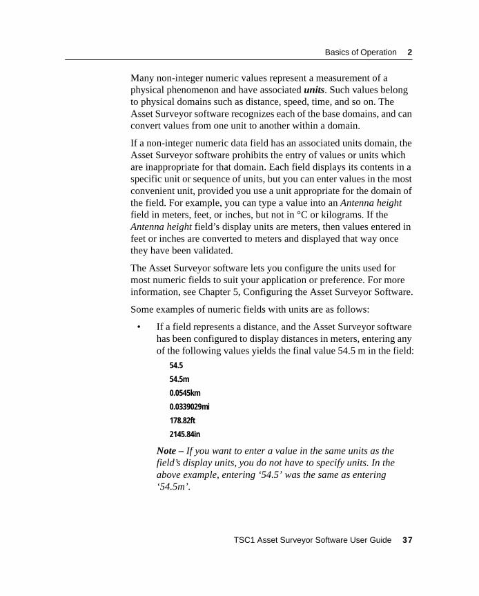
Some examples of numeric fields with units are as follows:
• If a field represents a distance, and the Asset Surveyor softwarehas been configured to display distances in meters, entering anyof the following values yields the final value 54.5 m in the field:
54.5
54.5m
0.0545km
0.0339029mi
178.82ft
2145.84in
Note – If you want to enter a value in the same units as thefield’s display units, you do not have to specify units. In theabove example, entering ‘54.5’ was the same as entering‘54.5m’.
TSC1 Asset Surveyor Software User Guide 37
2 Basics of Operation
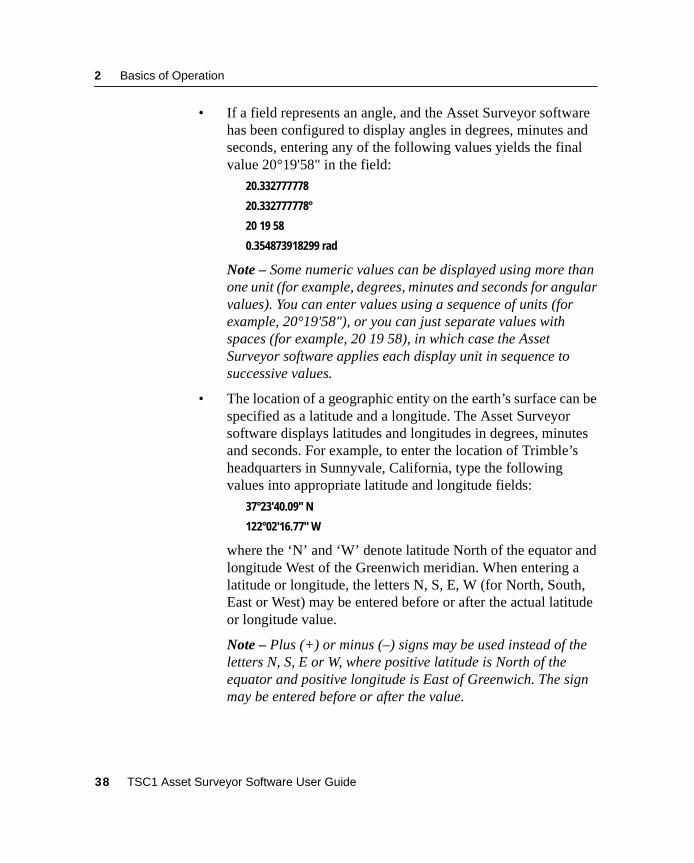
• If a field represents an angle, and the Asset Surveyor softwarehas been configured to display angles in degrees, minutes andseconds, entering any of the following values yields the finalvalue 20°19'58" in the field:
20.332777778
20.332777778°
20 19 58
0.354873918299 rad
Note – Some numeric values can be displayed using more thanone unit (for example, degrees, minutes and seconds for angularvalues). You can enter values using a sequence of units (forexample, 20°19'58"), or you can just separate values withspaces (for example, 20 19 58), in which case the AssetSurveyor software applies each display unit in sequence tosuccessive values.
• The location of a geographic entity on the earth’s surface can bespecified as a latitude and a longitude. The Asset Surveyorsoftware displays latitudes and longitudes in degrees, minutesand seconds. For example, to enter the location of Trimble’sheadquarters in Sunnyvale, California, type the followingvalues into appropriate latitude and longitude fields:
37°23'40.09" N
122°02'16.77" W
where the ‘N’ and ‘W’ denote latitude North of the equator andlongitude West of the Greenwich meridian. When entering alatitude or longitude, the letters N, S, E, W (for North, South,East or West) may be entered before or after the actual latitudeor longitude value.
Note – Plus (+) or minus (–) signs may be used instead of theletters N, S, E or W, where positive latitude is North of theequator and positive longitude is East of Greenwich. The signmay be entered before or after the value.
38 TSC1 Asset Surveyor Software User Guide
Basics of Operation 2
If you enter a position as a latitude and longitude, and do not explicitlyspecify the hemisphere, then the Asset Surveyor software assumes thatyou want the position to be in the hemisphere in which you arecurrently operating, as determined by your most recent GPS position.
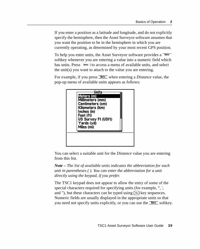
To help you enter units, the Asset Surveyor software provides aisoftkey whenever you are entering a value into a numeric field whichhas units. Pressi to access a menu of available units, and selectthe unit(s) you want to attach to the value you are entering.
For example, if you pressi when entering a Distance value, thepop-up menu of available units appears as follows:
You can select a suitable unit for the Distance value you are enteringfrom this list.
Note – The list of available units indicates the abbreviation for eachunit in parentheses ( ). You can enter the abbreviation for a unitdirectly using the keypad, if you prefer.
The TSC1 keypad does not appear to allow the entry of some of thespecial characters required for specifying units (for example, °, ',and "), but these characters can be typed using[ key sequences.Numeric fields are usually displayed in the appropriate units so thatyou need not specify units explicitly, or you can use thei softkey.
TSC1 Asset Surveyor Software User Guide 39
2 Basics of Operation
B Tip – Numeric attributes in data files use numeric fields. A numericattribute can be set up as an auto-incrementing attribute, whichautomatically generates a default value depending on the value enteredfor this attribute in the last feature you edited, and an increment ordecrement value specified in the data dictionary. For more information onauto-incrementing attributes, see Data Dictionaries, page 157.
Menu fields
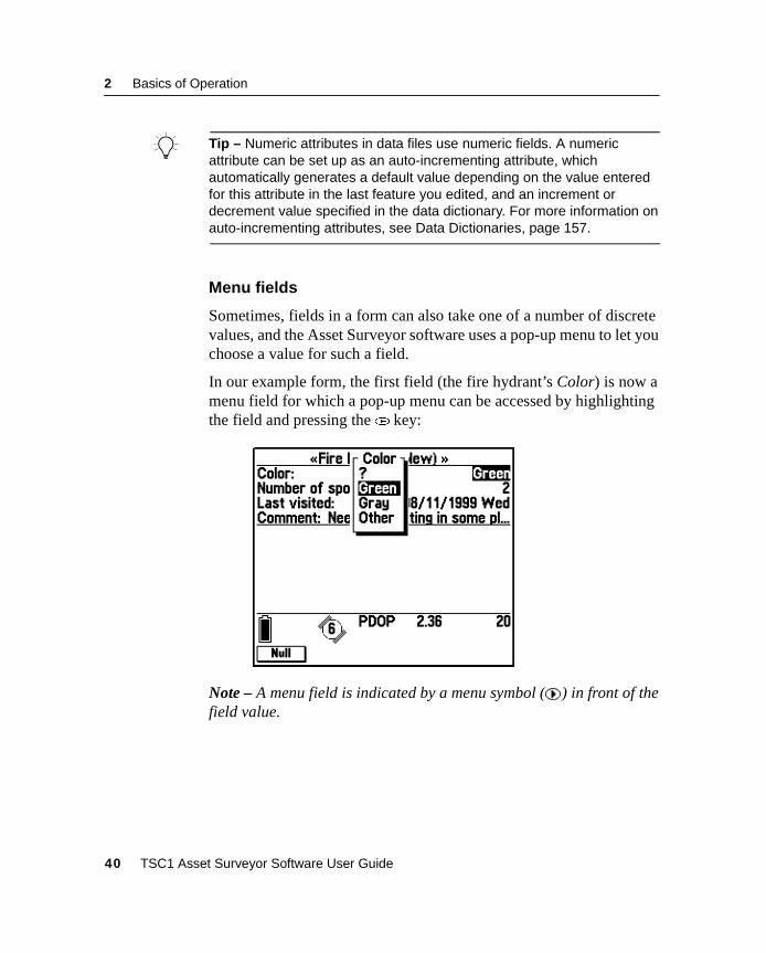
Sometimes, fields in a form can also take one of a number of discretevalues, and the Asset Surveyor software uses a pop-up menu to let youchoose a value for such a field.
In our example form, the first field (the fire hydrant’s Color) is now amenu field for which a pop-up menu can be accessed by highlightingthe field and pressing the( key:
Note – A menu field is indicated by a menu symbol ( ) in front of thefield value.
40 TSC1 Asset Surveyor Software User Guide
Basics of Operation 2
To select a new value for a menu field:
• Access the menu and select a value, as described for normalAsset Surveyor pop-up menus. You can access the menu for amenu field by positioning the highlight on that field andpressing( (the example form above shows the pop-up menuthat would appear by pressing( when the Color field washighlighted).
• Select a value immediately by typing its first letter. This is avery quick way to select a value for a menu, once you know thepossible values for that menu field. If the key you press does notcorrespond to the first letter of any entry in the menu, the menupops up so that you can see the list of possible values and thenselect one. Similarly, if the key you press corresponds to thefirst letter of more than one entry in the menu, the menu pops upand lets you see the various choices.
• Step backward through the values in the menu using the* key.When you use this method, the menu is circular, so if you reachthe first element in the menu and press* , you step to the lastelement in the menu.
The latter two methods of selecting values for menu fields areprovided for the convenience of experienced Asset Surveyor users.You may begin by accessing each menu and selecting from thedisplayed list of values, but as time goes by you can use theseshortcuts to make selecting values for menu fields even faster.
TSC1 Asset Surveyor Software User Guide 41
2 Basics of Operation
Date fields
A date field can be used to record a calendar date. Different countriesuse different conventions for the entry and display of calendar dates.The Asset Surveyor software can be configured to display dates in thefollowing formats:
• MM/DD/YYYY
• DD/MM/YYYY
• YYYY/MM/DD
where MM represents the month, DD the day, and YYYY the year.For example, in MM/DD/YYYY format, the 4th of July 1976 wouldbe displayed as:
07/04/1976
Note – If you enter a two-digit year between 00 and 29, the AssetSurveyor software stores it as 20XX (for example, if you enter 15 it isstored as 2015). If you enter a two-digit year from 30 to 99, it is storedas 19XX. If you want to enter a date from a different century, type theyear in full with four digits.
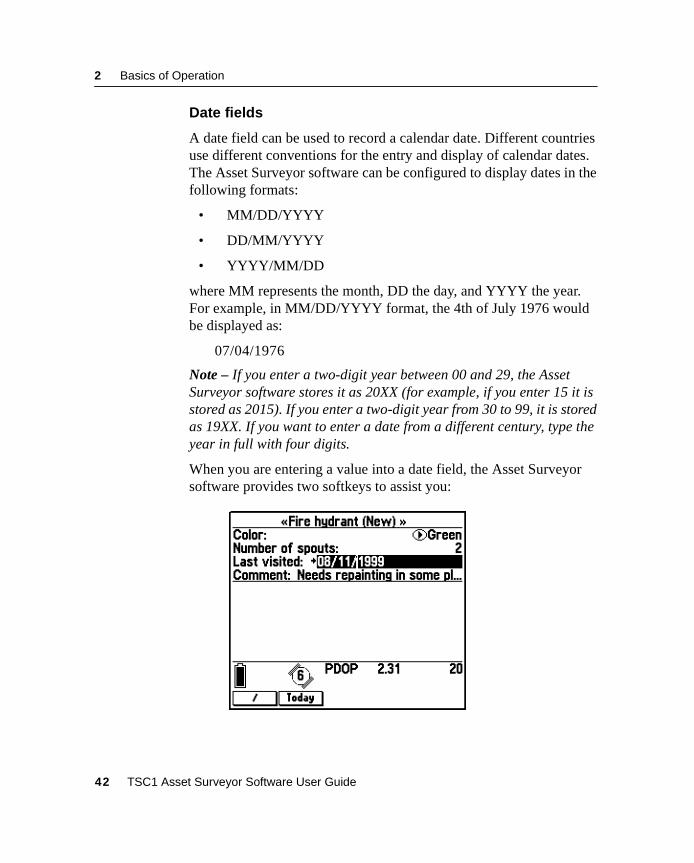
When you are entering a value into a date field, the Asset Surveyorsoftware provides two softkeys to assist you:
42 TSC1 Asset Surveyor Software User Guide
Basics of Operation 2
The/ softkey is a faster way to enter the ‘/’ character than typingon the TSC1 keypad. You can also type the[d sequence on theTSC1 keypad to obtain the ‘/’ character.
Note – The Asset Surveyor software also accepts dates entered withspaces between the components, for example ‘7 4 76’, but alwaysformats and displays dates with the ‘/’ character as a separator.
TheH softkey lets you quickly fill in the field with the current date(as determined from the TSC1 datalogger’s internal clock). ManyAsset Surveyor date fields are filled in with the current dateautomatically, and you only need to enter the date manually if thisautomatic date is incorrect.
The Asset Surveyor software automatically works out the day of theweek from the date that you have entered, and displays it as a means ofchecking that you have entered the correct date.
Time fields
A time field is used to store the time of day, and may either be filled inautomatically from the TSC1 datalogger’s internal clock, or enteredmanually. If a GPS receiver is currently connected, the clock isprecisely aligned to UTC time.
Note – A time field is not used for storing elapsed time (for example,the amount of time taken for an athlete to complete a race); this isbetter represented as a numeric field.
Hours, minutes and seconds are separated by a colon (:) character.Times are displayed using either 12- or 24-hour clock format. In the24-hour clock format, 4:30 P.M. is displayed as ‘16:30’. The AssetSurveyor software allows the entry of time in either format. If theentered time is less than ‘12:00’, and ‘p.m.’ is not specified, then thesoftware assumes the time is before noon. The Asset Surveyorsoftware can be configured to display times in either format.
TSC1 Asset Surveyor Software User Guide 43

2 Basics of Operation
When you are entering a value into a time field, the Asset Surveyorsoftware makes four softkeys available to assist you:
• The: softkey is a faster way to enter a colon than typing onthe TSC1 keypad. You can also type the[p sequence on theTSC1 keypad to enter a colon.
Note – The Asset Surveyor software also accepts times enteredwith spaces between the components, for example ‘4 30 00’, butalways formats and displays times with the ‘:’ character as aseparator. Neither minutes nor seconds need be entered, but ifminutes are desired then hours must be present, and if secondsare desired then both hours and minutes are required. Forexample, 10 o’clock in the evening could be entered as ‘10pm’,‘22’, ‘10:00pm’, ‘22:00’, ‘10:00:00pm’, ‘22:00:00’, or‘10:0:0pm’.
• You can press8 to fill in the field with the current time.Many Asset Surveyor time fields are filled in with the currenttime automatically and you only need to enter the timemanually if this automatic time is incorrect.
• You can press4 to insert the character sequence ‘am’ intothe field. This is generally unnecessary, as the Asset Surveyorsoftware presumes that a time less than 12:00 falls in themorning, in the absence of any explicit ‘pm’ indication.
• You can press5 to insert the character sequence ‘pm’ intothe field. This is necessary if you want to enter a time after noonin 12-hour format.
44 TSC1 Asset Surveyor Software User Guide
Basics of Operation 2
2.7 File Naming ConventionsThe Asset Surveyor software is designed primarily to collect GIS andGPS data and to store this data in files on the TSC1 datalogger. Thesefiles can be individually named, but because you may need to collect avast quantity of data which is all very similar in nature, it can bedifficult to think of meaningful yet distinct names for data files. TheAsset Surveyor software automatically suggests a name for each newdata file when it is created.
For the purposes of automatic naming, Asset Surveyor data files aredivided into two classes: rover and base station files. Most data filesare rover files. The Asset Surveyor software lets you collect GISfeature and attribute information to rover files, along with GPSpositions, and so on. The Asset Surveyor software also lets you useyour Trimble GPS receiver as a GPS base station, which results in thecreation and recording of base station files. Operating an AssetSurveyor base station is described in detail in Chapter 3, DataCollection.
When a rover data file is created, the Asset Surveyor softwaresuggests a default filename according to the following formula:
• R MM DD HH x
where the initial letter ‘R’ identifies the data file as being a rover file,MM is the current month, DD is the current day of the month, and HHis the current hour of the day. The final letter ‘x’ increments withinthis hour, starting at ‘a’ for the first file in that hour, then going to ‘b’for the second file and ‘c’ for the third file, and so on.
Note – The date and time used for naming of data files is, by default,UTC (GMT) time. You can specify that the Asset Surveyor softwareshould use local time to name rover files by pressingt andselecting Local from the pop-up menu. If the default filename looksodd, check that the TSC1 datalogger’s internal time and date are setcorrectly.
TSC1 Asset Surveyor Software User Guide 45
2 Basics of Operation
B Tip – The initial letter ‘R’ can be changed, in which case subsequent roverdata files are given the new initial letter. This lets you uniquely name datafiles from a fleet of Asset Surveyor rovers, using initial letters like ‘X’, ‘Y’,‘Z’. To change the initial letter of a filename to ‘X’, simply type ‘X’ and thenpress\ to move on to the next field in the form. The Asset Surveyorsoftware automatically regenerates the default filename with an ‘X’ prefix.
Some examples of default rover filenames for the morning of the 15thof September are:
• R091510a
• R091510b
• R091511a
Remember that the default filename suggested by the Asset Surveyorsoftware is simply a suggestion. You can change the suggested nameor enter an entirely different name. You can use such filenames as:
• SURVEY1
• SC0090
• RONALD
Filenames can be up to eight characters long, and are composed ofletters and digits only (that is, no spaces or punctuation characters arepermitted).
Trimble suggests, however, that unless you are dealing with a smallnumber of data files at a time, you should consider using the automaticfilenames as these assist with identifying files by time and date.
The Asset Surveyor software suggests default names for base fileswhich are formatted slightly differently from those suggested for roverfiles. They follow the formula:
• B Y MM DD HH
where ‘B’ identifies the file as being a base station file, Y is the lastdigit of the current year, MM is the current month, DD is the currentday of the month and HH is the current hour of the day.
46 TSC1 Asset Surveyor Software User Guide
Basics of Operation 2
Note – As with rover files, the default base filename can beconstructed using either local or UTC (GMT) time, the default beingUTC. Press thet softkey to select which time system you want tobe used for base station filenames.
B Tip – As with default rover filenames, the initial character ‘B’ of a defaultbase filename can be changed, in which case subsequent base data filesare given the new initial character. This lets you conveniently name datafiles from a number of base stations separately. For example, Bases A toC could use the initial letters ‘A’, ‘B’, and ‘C’.
Some examples of default base filenames for the morning of the 25thof January 1995 are:
• B5012510
• B5012511
• B5012512
As with rover files, you can edit the suggested filename or replace itentirely, but Trimble suggests that you use the default names for basefiles so that they are consistent with base files from other Trimbleproducts and because the time and date of a base file is crucial to itsuse for differentially correcting rover files.
Note – You can configure the Trimble Reference Station (TRS™)software to use either local time or UTC (GMT) time to construct basefilenames. When matching base and rover files for differentialcorrection, you must be aware of the naming conventions and timescales used by this software system.
TSC1 Asset Surveyor Software User Guide 47
2 Basics of Operation
2.8 Software and Firmware Version NumbersIf you ever need to call Trimble Navigation Limited with questionsabout the Asset Surveyor software, you should first determine thesoftware version you are currently running, using the aboveprocedure.
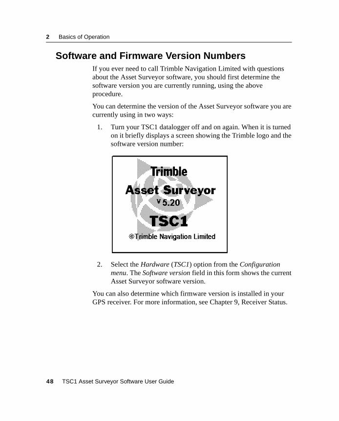
You can determine the version of the Asset Surveyor software you arecurrently using in two ways:
1. Turn your TSC1 datalogger off and on again. When it is turnedon it briefly displays a screen showing the Trimble logo and thesoftware version number:
2. Select the Hardware (TSC1) option from the Configurationmenu. The Software version field in this form shows the currentAsset Surveyor software version.
You can also determine which firmware version is installed in yourGPS receiver. For more information, see Chapter 9, Receiver Status.
48 TSC1 Asset Surveyor Software User Guide

C H A P T E R
3
3 Data CollectionIn this chapter:
■ Introduction
■ Collecting new features
■ Data review and update
■ Create base file
3 Data Collection
3.1 IntroductionThis chapter provides information on rover data collection. The datacollection procedure can be broken up into two key operations:
• The collection of new features
• The review and/or update of existing features
The following sections provide a detailed description of how tosuccessfully carry out these operations using the Asset Surveyorsoftware.
This chapter also provides information on logging base data files.
3.2 Collecting New FeaturesThis section describes how to use the Asset Surveyor software tocreate new data files and collect new features to files.
For a description of the review and update capabilities in the AssetSurveyor software, see Data Review and Update, page 80.
50 TSC1 Asset Surveyor Software User Guide
Data Collection 3
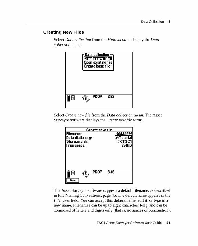
3.2.1 Creating New Files
Select Data collection from the Main menu to display the Datacollection menu:
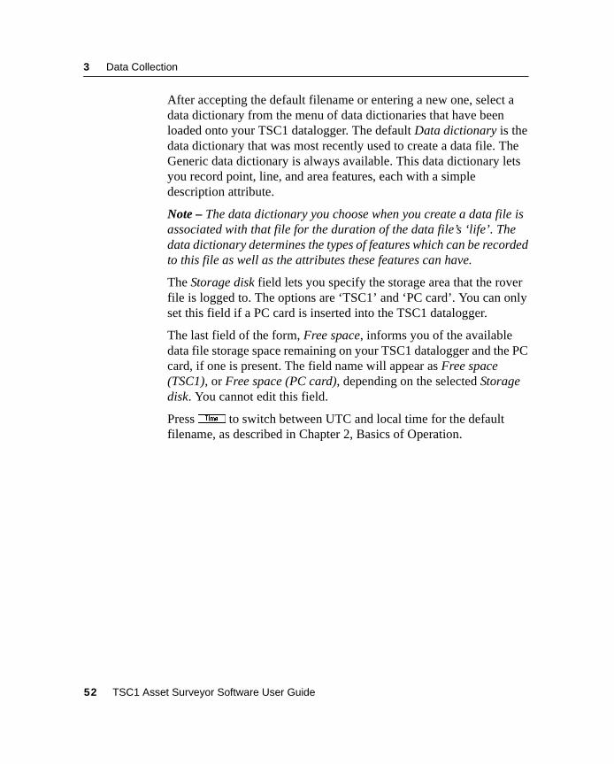
Select Create new file from the Data collection menu. The AssetSurveyor software displays the Create new file form:
The Asset Surveyor software suggests a default filename, as describedin File Naming Conventions, page 45. The default name appears in theFilename field. You can accept this default name, edit it, or type in anew name. Filenames can be up to eight characters long, and can becomposed of letters and digits only (that is, no spaces or punctuation).
TSC1 Asset Surveyor Software User Guide 51
3 Data Collection
After accepting the default filename or entering a new one, select adata dictionary from the menu of data dictionaries that have beenloaded onto your TSC1 datalogger. The default Data dictionary is thedata dictionary that was most recently used to create a data file. TheGeneric data dictionary is always available. This data dictionary letsyou record point, line, and area features, each with a simpledescription attribute.
Note – The data dictionary you choose when you create a data file isassociated with that file for the duration of the data file’s ‘life’. Thedata dictionary determines the types of features which can be recordedto this file as well as the attributes these features can have.
The Storage disk field lets you specify the storage area that the roverfile is logged to. The options are ‘TSC1’ and ‘PC card’. You can onlyset this field if a PC card is inserted into the TSC1 datalogger.
The last field of the form, Free space, informs you of the availabledata file storage space remaining on your TSC1 datalogger and the PCcard, if one is present. The field name will appear as Free space(TSC1), or Free space (PC card), depending on the selected Storagedisk. You cannot edit this field.
Presst to switch between UTC and local time for the defaultfilename, as described in Chapter 2, Basics of Operation.
52 TSC1 Asset Surveyor Software User Guide
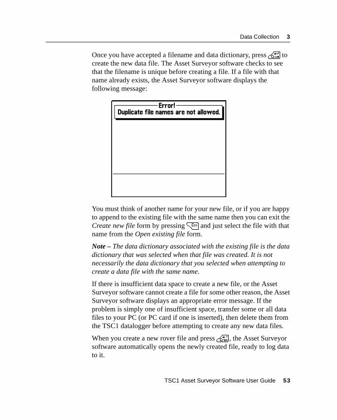
Data Collection 3
Once you have accepted a filename and data dictionary, press\ tocreate the new data file. The Asset Surveyor software checks to seethat the filename is unique before creating a file. If a file with thatname already exists, the Asset Surveyor software displays thefollowing message:
You must think of another name for your new file, or if you are happyto append to the existing file with the same name then you can exit theCreate new file form by pressing= and just select the file with thatname from the Open existing file form.
Note – The data dictionary associated with the existing file is the datadictionary that was selected when that file was created. It is notnecessarily the data dictionary that you selected when attempting tocreate a data file with the same name.
If there is insufficient data space to create a new file, or the AssetSurveyor software cannot create a file for some other reason, the AssetSurveyor software displays an appropriate error message. If theproblem is simply one of insufficient space, transfer some or all datafiles to your PC (or PC card if one is inserted), then delete them fromthe TSC1 datalogger before attempting to create any new data files.
When you create a new rover file and press\ , the Asset Surveyorsoftware automatically opens the newly created file, ready to log datato it.
TSC1 Asset Surveyor Software User Guide 53
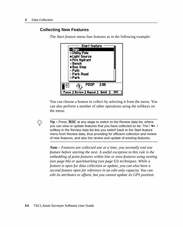
3 Data Collection
3.2.2 Collecting New Features
The Start feature menu lists features as in the following example:
You can choose a feature to collect by selecting it from the menu. Youcan also perform a number of other operations using the softkeys onthe menu.
B Tip – Press{ at any stage to switch to the Review data list, whereyou can view or update features that you have collected so far. Thebsoftkey in the Review data list lets you switch back to the Start featuremenu from Review data, thus providing for efficient collection and reviewof new features, and also the review and update of existing features.
Note – Features are collected one at a time; you normally end onefeature before starting the next. A useful exception to this rule is theembedding of point features within line or area features using nesting(see page 66) or quickmarking (see page 63) techniques. While afeature is open for data collection or update, you can also have asecond feature open for reference in an edit-only capacity. You canedit its attributes or offsets, but you cannot update its GPS position.
54 TSC1 Asset Surveyor Software User Guide
Data Collection 3
3.2.3 Selecting a Feature to Collect
When you select a feature from the Start feature menu, the AssetSurveyor software starts to collect data for that feature. This includes:
• the GPS position of the feature
• an optional offset to the GPS position
• attributes of the feature (entered using the TSC1 keypad)
• any external sensor data which might be recorded for thatfeature
Provided a GPS receiver is connected and operational, the AssetSurveyor software records GPS positions automatically for thefeature, according to the way that you have configured the GPSinterface. If you have configured and activated an external sensor,external sensor data is also recorded automatically. If you haveconfigured and activated a laser rangefinder, you can record an offsetfor the feature by aiming and firing the rangefinder. Alternatively, youcan measure and enter the offset manually.
By taking care of GPS and external sensor data collection, and byintegrating the recording of an optional offset to each feature, theAsset Surveyor software lets you concentrate on entering attributevalues for the feature.
TSC1 Asset Surveyor Software User Guide 55
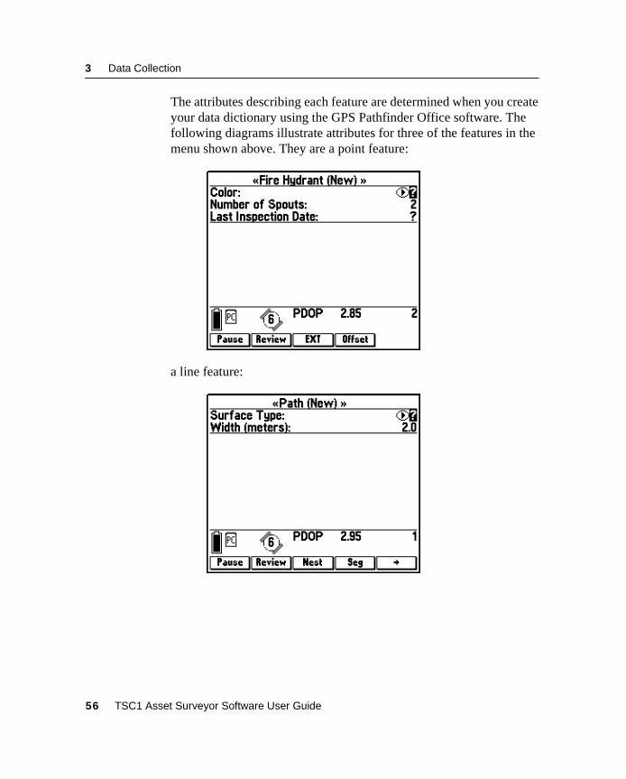
3 Data Collection
The attributes describing each feature are determined when you createyour data dictionary using the GPS Pathfinder Office software. Thefollowing diagrams illustrate attributes for three of the features in themenu shown above. They are a point feature:
a line feature:
56 TSC1 Asset Surveyor Software User Guide
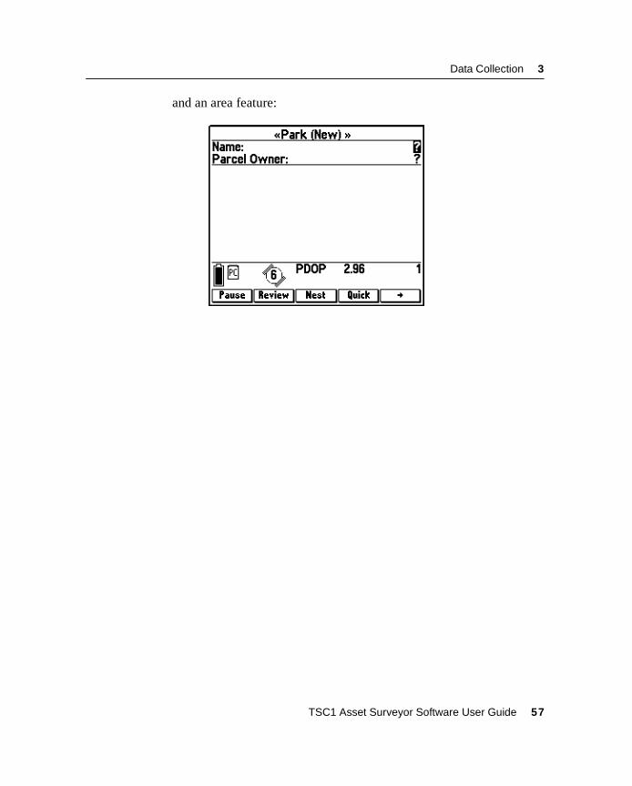
Data Collection 3
and an area feature:
TSC1 Asset Surveyor Software User Guide 57
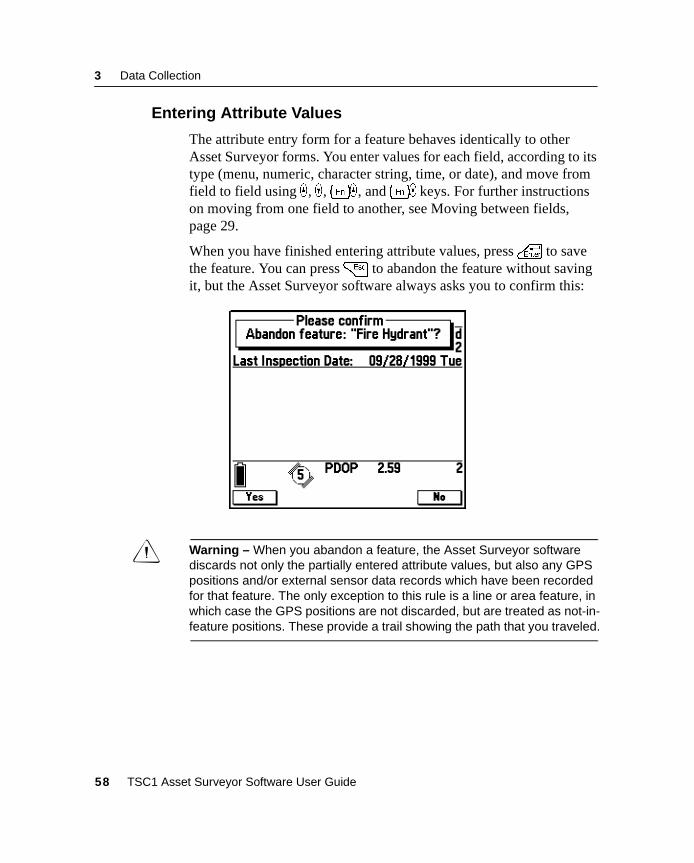
3 Data Collection
3.2.4 Entering Attribute Values
The attribute entry form for a feature behaves identically to otherAsset Surveyor forms. You enter values for each field, according to itstype (menu, numeric, character string, time, or date), and move fromfield to field using _ , ) ,[_ , and[) keys. For further instructionson moving from one field to another, see Moving between fields,page 29.
When you have finished entering attribute values, press\ to savethe feature. You can press= to abandon the feature without savingit, but the Asset Surveyor software always asks you to confirm this:
C Warning – When you abandon a feature, the Asset Surveyor softwarediscards not only the partially entered attribute values, but also any GPSpositions and/or external sensor data records which have been recordedfor that feature. The only exception to this rule is a line or area feature, inwhich case the GPS positions are not discarded, but are treated as not-in-feature positions. These provide a trail showing the path that you traveled.
58 TSC1 Asset Surveyor Software User Guide
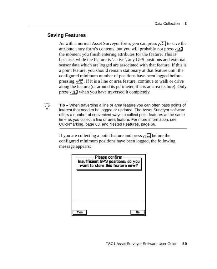
Data Collection 3
3.2.5 Saving Features
As with a normal Asset Surveyor form, you can press\ to save theattribute entry form’s contents, but you will probably not press\the moment you finish entering attributes for the feature. This isbecause, while the feature is ‘active’, any GPS positions and externalsensor data which are logged are associated with that feature. If this isa point feature, you should remain stationary at that feature until theconfigured minimum number of positions have been logged beforepressing\ . If it is a line or area feature, continue to walk or drivealong the feature (or around its perimeter, if it is an area feature). Onlypress\ when you have traversed it completely.
B Tip – When traversing a line or area feature you can often pass points ofinterest that need to be logged or updated. The Asset Surveyor softwareoffers a number of convenient ways to collect point features at the sametime as you collect a line or area feature. For more information, seeQuickmarking, page 63, and Nested Features, page 66.
If you are collecting a point feature and press\ before theconfigured minimum positions have been logged, the followingmessage appears:
TSC1 Asset Surveyor Software User Guide 59
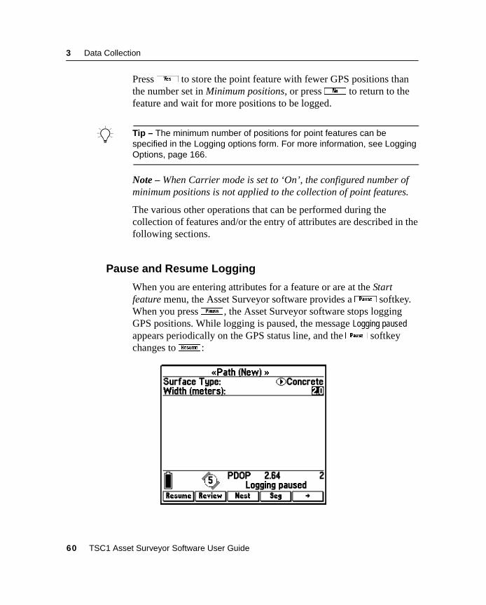
3 Data Collection
Pressy to store the point feature with fewer GPS positions thanthe number set in Minimum positions, or pressn to return to thefeature and wait for more positions to be logged.
B Tip – The minimum number of positions for point features can bespecified in the Logging options form. For more information, see LoggingOptions, page 166.
Note – When Carrier mode is set to ‘On’, the configured number ofminimum positions is not applied to the collection of point features.
The various other operations that can be performed during thecollection of features and/or the entry of attributes are described in thefollowing sections.
3.2.6 Pause and Resume Logging
When you are entering attributes for a feature or are at the Startfeature menu, the Asset Surveyor software provides ap softkey.When you pressp , the Asset Surveyor software stops loggingGPS positions. While logging is paused, the message Logging pausedappears periodically on the GPS status line, and thep softkeychanges toL :
60 TSC1 Asset Surveyor Software User Guide
Data Collection 3
When you pressL , the Asset Surveyor software resumes loggingand the softkey reverts back top .
Pressp whenever you want to stop briefly, or if you are collectinga line or area feature and have to travel around some obstacle beforepicking up the line or area perimeter again. You should also usepif you want to nest a point feature within a line or area, and the pointlies some way off the line or area perimeter. You can then nest thepoint without ending up with a ‘spike’ in the line or area.
C Warning – When GPS logging is paused, the Asset Surveyor softwaredoes not record GPS positions, external sensor data, velocities, or PPRTfields, but continues to record carrier measurements (if Carrier mode isset to ‘On’) and certain critical GPS information that is required forpostprocessing. This additional information is relatively small, but it ispossible that even when logging is paused your TSC1 datalogger mayeventually run out of data storage space.
Each time you resume logging while collecting a line or area feature,the Asset Surveyor software logs a GPS position (irrespective of thelogging interval for line or area features).
B Tip – You can use this feature to make the Asset Surveyor software log aGPS position when you come to a corner or a point of interest whilecollecting a line or area feature. Pressp and thenL to cause thecurrent GPS position to be logged. After you pressL , the AssetSurveyor software continues to log GPS positions at the configured line orarea logging interval.
TSC1 Asset Surveyor Software User Guide 61
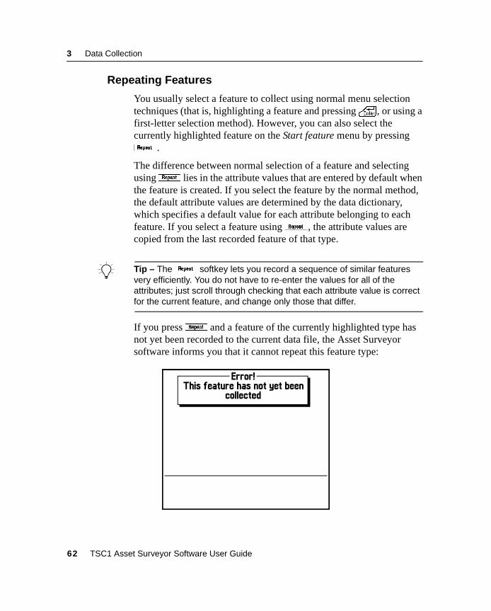
3 Data Collection
3.2.7 Repeating Features
You usually select a feature to collect using normal menu selectiontechniques (that is, highlighting a feature and pressing\ , or using afirst-letter selection method). However, you can also select thecurrently highlighted feature on the Start feature menu by pressingJ .
The difference between normal selection of a feature and selectingusingJ lies in the attribute values that are entered by default whenthe feature is created. If you select the feature by the normal method,the default attribute values are determined by the data dictionary,which specifies a default value for each attribute belonging to eachfeature. If you select a feature usingJ , the attribute values arecopied from the last recorded feature of that type.
B Tip – TheJ softkey lets you record a sequence of similar featuresvery efficiently. You do not have to re-enter the values for all of theattributes; just scroll through checking that each attribute value is correctfor the current feature, and change only those that differ.
If you pressJ and a feature of the currently highlighted type hasnot yet been recorded to the current data file, the Asset Surveyorsoftware informs you that it cannot repeat this feature type:
62 TSC1 Asset Surveyor Software User Guide
Data Collection 3
You must first log a feature using the normal method before you canrepeat it.
The feature that is repeated is normally the last feature of that type thatwas collected. However, you can repeat the attributes of any feature inthe file by highlighting it on the Review data list and opening it forattribute review before you pressJ .
Note – Offsets, except those configured as constant offsets, are notrepeated whenJ is pressed.
3.2.8 Quickmarking
The Asset Surveyor software provides two ways to collect the GPSposition of a point feature. The usual way is to select a point featurefrom the Start feature or Nest feature menu, and to stay at that featurelong enough to log sufficient GPS positions. Another way is to recorda quickmark.
A quickmark is recorded by simply pressing a button on the TSC1datalogger as you drive, fly, or move past a feature. With quickmarks,the Asset Surveyor software cannot record a number of positions toaverage together. In fact, the software cannot necessarily even record asingle GPS position at exactly the moment that you pass the feature. Ittherefore records an accurate time (using the very precise GPSsatellite timers to keep the TSC1 datalogger’s clock perfectlysynchronized). This time is used to compute an interpolated positionfor the quickmark based on two GPS positions: the one logged beforeyou passed the feature and one logged after.
The accuracy of quickmarks is not as high as the accuracy you canachieve by standing at a point and logging positions for some time, butyou can use quickmarks to rapidly record reasonably accurate GPSpositions for a large number of features.
B Tip – Because quickmarks are recorded to the nearest second, if youtravel more slowly the quickmarks that you record will be more accurate.
TSC1 Asset Surveyor Software User Guide 63
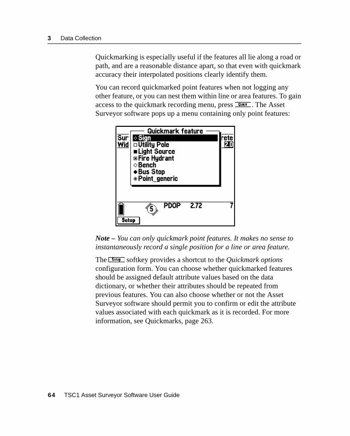
3 Data Collection
Quickmarking is especially useful if the features all lie along a road orpath, and are a reasonable distance apart, so that even with quickmarkaccuracy their interpolated positions clearly identify them.
You can record quickmarked point features when not logging anyother feature, or you can nest them within line or area features. To gainaccess to the quickmark recording menu, pressq . The AssetSurveyor software pops up a menu containing only point features:
Note – You can only quickmark point features. It makes no sense toinstantaneously record a single position for a line or area feature.
TheS softkey provides a shortcut to the Quickmark optionsconfiguration form. You can choose whether quickmarked featuresshould be assigned default attribute values based on the datadictionary, or whether their attributes should be repeated fromprevious features. You can also choose whether or not the AssetSurveyor software should permit you to confirm or edit the attributevalues associated with each quickmark as it is recorded. For moreinformation, see Quickmarks, page 263.
64 TSC1 Asset Surveyor Software User Guide
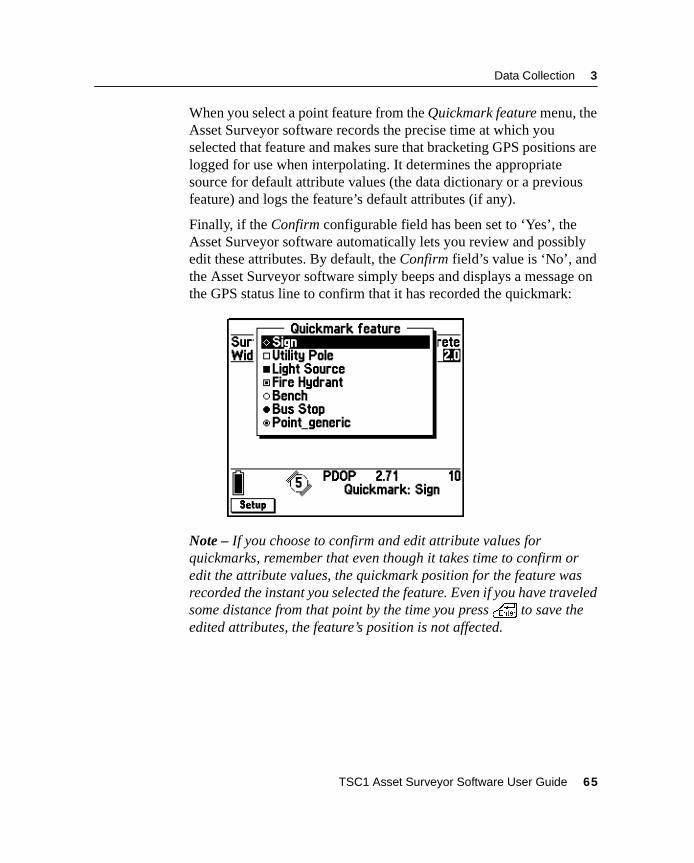
Data Collection 3
When you select a point feature from the Quickmark feature menu, theAsset Surveyor software records the precise time at which youselected that feature and makes sure that bracketing GPS positions arelogged for use when interpolating. It determines the appropriatesource for default attribute values (the data dictionary or a previousfeature) and logs the feature’s default attributes (if any).
Finally, if the Confirm configurable field has been set to ‘Yes’, theAsset Surveyor software automatically lets you review and possiblyedit these attributes. By default, the Confirm field’s value is ‘No’, andthe Asset Surveyor software simply beeps and displays a message onthe GPS status line to confirm that it has recorded the quickmark:
Note – If you choose to confirm and edit attribute values forquickmarks, remember that even though it takes time to confirm oredit the attribute values, the quickmark position for the feature wasrecorded the instant you selected the feature. Even if you have traveledsome distance from that point by the time you press\ to save theedited attributes, the feature’s position is not affected.
TSC1 Asset Surveyor Software User Guide 65
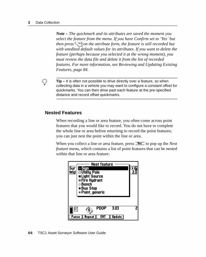
3 Data Collection
Note – The quickmark and its attributes are saved the moment youselect the feature from the menu. If you have Confirm set to ‘Yes’ butthen press= on the attribute form, the feature is still recorded butwith unedited default values for its attributes. If you want to delete thefeature (perhaps because you selected it at the wrong moment), youmust review the data file and delete it from the list of recordedfeatures. For more information, see Reviewing and Updating ExistingFeatures, page 84.
B Tip – It is often not possible to drive directly over a feature, so whencollecting data in a vehicle you may want to configure a constant offset forquickmarks. You can then drive past each feature at the pre-specifieddistance and record offset quickmarks.
3.2.9 Nested Features
When recording a line or area feature, you often come across pointfeatures that you would like to record. You do not have to completethe whole line or area before returning to record the point features;you can just nest the point within the line or area.
When you collect a line or area feature, pressN to pop up the Nestfeature menu, which contains a list of point features that can be nestedwithin that line or area feature:
66 TSC1 Asset Surveyor Software User Guide
Data Collection 3
Until you actually select a point feature to nest, any GPS positionslogged belong to the outer line or area feature.
PressA to open the Update point feature menu, where you can nestthe update of an existing point feature. You can do this while updatingan existing line or area feature, or while logging a new one. On theUpdate point feature menu, theA softkey changes tob . Pressb to return to the Nest feature menu.
To nest a point feature that lies off the perimeter of the line or areafeature:
1. Pressp to pause logging to the line or area.
2. Travel to the point feature in question.
3. From the Nest new feature menu, select the appropriate pointfeature, or pressA and select an existing feature to update.
When you are ready to record GPS positions for this feature,pressL if it is a new feature, or3 if it is an existingfeature. Logging begins and continues until you save the nestedfeature or until you pressp again.
4. When you have finished recording attributes for the pointfeature and have logged sufficient GPS positions, press\ tosave the feature.
The Asset Surveyor software automatically pauses logging andreturns you to the attribute entry form for the outer line or areafeature.
5. Do one of the following:
– PressN again to nest another point feature (and repeatsteps 2 to 4).
– Go back to the line or area’s perimeter and pressL toresume logging of GPS positions for the line or area.
TSC1 Asset Surveyor Software User Guide 67
3 Data Collection
B Tip – You can select the end of the line feature as the Target and use theAsset Surveyor software’s navigation functionality to guide you back to it,ready to continue logging.
You can nest as many point features within a line or area as necessary(limited only by storage space on the TSC1 datalogger).
When you have traversed the line or area’s perimeter, press\ tosave that feature.
B Tip – If you are traveling rapidly, the points you want to nest have fewattributes, and their positions need not be as accurate as averaged pointfeatures, consider quickmarking them instead of nesting them. Recordingquickmarks is very rapid and efficient.
If you select a point feature to nest from the menu, it has defaultattribute values as defined in the data dictionary. You can nest a pointfeature with the same default attributes as the previously recordedfeature of that type by highlighting the feature in the Nest featuremenu and pressingJ .
B Tip – You can nest a point feature with the same attributes as any featurein the file by highlighting the feature on the Review data list and openingthe feature for review before you pressJ .
68 TSC1 Asset Surveyor Software User Guide
Data Collection 3
3.2.10 Segmented Line Features
When collecting line features, it is often convenient to divide a lineinto a number of segments. Segmentation of lines lets you specifydiffering attribute values for parts of the same physical line.Segmentation also lets you end one line feature and immediately startanother (of the same type) while you are still moving. This is veryuseful if you are mapping roads or highways where it can be difficultor illegal to stop at a point where one feature ends and the next featurestarts.
B Tip – Because the segment position is recorded to the nearest second, ifyou travel more slowly the positions you record will be more accurate.
To segment a line feature, presss . The current line feature issaved and another line feature of the same type is immediately startedwith the same attribute values as the previous feature. The last GPSposition of the first segment is identical to the first GPS position of thesecond segment, so that adjacent segments are joined end-to-end inyour GIS.
C Warning – When you presss , the Asset Surveyor software validatesthe first line feature’s attributes. If you have not finished entering theattributes for that line segment, the Asset Surveyor software does not letyou save the feature. You must complete attribute entry before pressing\ ors again to save that feature. In the meantime, you must stopuntil the first feature has been completed.
C Warning – If there is no current GPS position available when you presss (due, for example, to a high PDOP situation), the Asset Surveyorsoftware does not start the new line segment with the last GPS position ofthe previous line segment. Instead, the new line segment starts from thefirst GPS position that becomes available after you presss . TheAsset Surveyor software may also start the new line segment at a positionother than the precise end of the previous line segment if a satelliteconstellation change occurs at the moments is pressed.
TSC1 Asset Surveyor Software User Guide 69
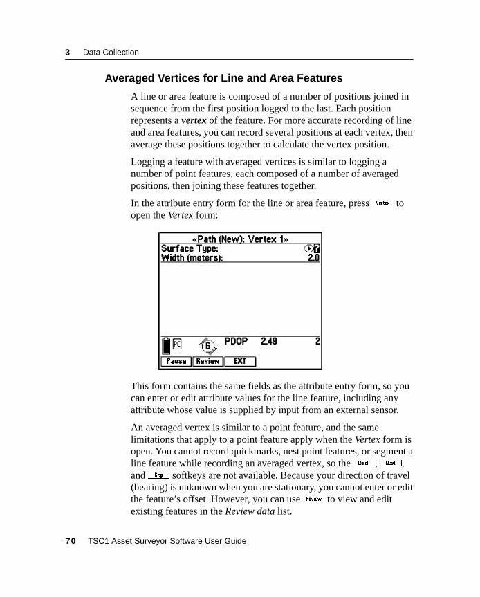
3 Data Collection
3.2.11 Averaged Vertices for Line and Area Features
A line or area feature is composed of a number of positions joined insequence from the first position logged to the last. Each positionrepresents a vertex of the feature. For more accurate recording of lineand area features, you can record several positions at each vertex, thenaverage these positions together to calculate the vertex position.
Logging a feature with averaged vertices is similar to logging anumber of point features, each composed of a number of averagedpositions, then joining these features together.
In the attribute entry form for the line or area feature, press, toopen the Vertex form:
This form contains the same fields as the attribute entry form, so youcan enter or edit attribute values for the line feature, including anyattribute whose value is supplied by input from an external sensor.
An averaged vertex is similar to a point feature, and the samelimitations that apply to a point feature apply when the Vertex form isopen. You cannot record quickmarks, nest point features, or segment aline feature while recording an averaged vertex, so theq,N,ands softkeys are not available. Because your direction of travel(bearing) is unknown when you are stationary, you cannot enter or editthe feature’s offset. However, you can use{ to view and editexisting features in the Review data list.
70 TSC1 Asset Surveyor Software User Guide
Data Collection 3
While the Vertex form is open, you must remain stationary, as thoughyou were recording a point feature. The messages Remain stationary andVertex open flash alternately in the status line to remind you to stay still.The number of positions recorded for this vertex also appears in thestatus line. When you have logged as many positions as you requirefor this vertex, close the Vertex form. You are returned to the attributeentry form.
A line or area feature can include both averaged vertices and positionslogged normally as you travel. If you want to record only averagedvertices, you must pause logging before you open the feature.Whenever you open the Vertex form, logging starts, and when youclose the Vertex form, logging returns to its former state. Thistechnique ensures that no positions are logged except those you log foraveraged vertices. While the Vertex form is open, thep andLsoftkeys control logging of positions for the current vertex.
TSC1 Asset Surveyor Software User Guide 71
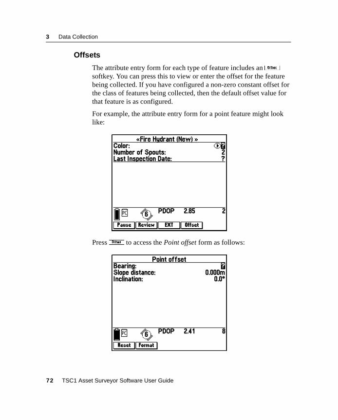
3 Data Collection
3.2.12 Offsets
The attribute entry form for each type of feature includes anOsoftkey. You can press this to view or enter the offset for the featurebeing collected. If you have configured a non-zero constant offset forthe class of features being collected, then the default offset value forthat feature is as configured.
For example, the attribute entry form for a point feature might looklike:
PressO to access the Point offset form as follows:
72 TSC1 Asset Surveyor Software User Guide
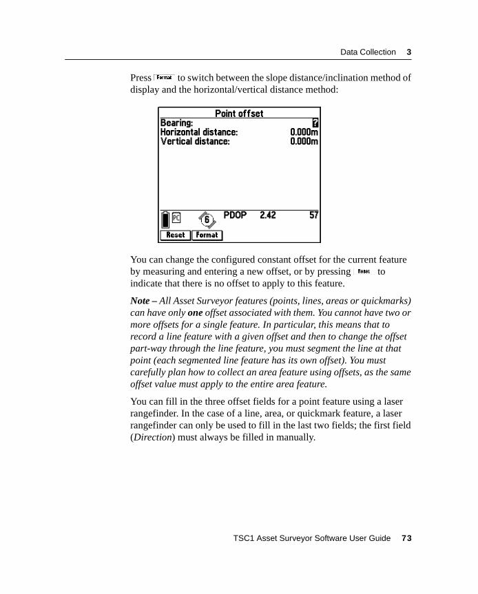
Data Collection 3
Pressf to switch between the slope distance/inclination method ofdisplay and the horizontal/vertical distance method:
You can change the configured constant offset for the current featureby measuring and entering a new offset, or by pressingK toindicate that there is no offset to apply to this feature.
Note – All Asset Surveyor features (points, lines, areas or quickmarks)can have only one offset associated with them. You cannot have two ormore offsets for a single feature. In particular, this means that torecord a line feature with a given offset and then to change the offsetpart-way through the line feature, you must segment the line at thatpoint (each segmented line feature has its own offset). You mustcarefully plan how to collect an area feature using offsets, as the sameoffset value must apply to the entire area feature.
You can fill in the three offset fields for a point feature using a laserrangefinder. In the case of a line, area, or quickmark feature, a laserrangefinder can only be used to fill in the last two fields; the first field(Direction) must always be filled in manually.
TSC1 Asset Surveyor Software User Guide 73
3 Data Collection
When you transfer features from the GPS Pathfinder Office software,their offsets are transferred as well. However, unless you have updatedan offset in the same data collection session, it is reset to the currentconstant offset value if the feature’s GPS position is updated. Whenthis happens the Asset Surveyor software shows the message Existingoffset reset.
When using a laser rangefinder, you do not have to visit the offsetform for a point feature; simply use the laser to record the offset andwatch for an Offset received message on the GPS status line. For line,area, and quickmark features, however, you must visit the offset formbefore you can record an offset using a laser rangefinder. This isbecause you have to specify the Direction of the offset relative to yourcurrent direction of travel.
74 TSC1 Asset Surveyor Software User Guide
Data Collection 3
3.2.13 External Sensors
You can use external sensors to collect data with the Asset Surveyorsoftware.
EXT softkey
When collecting data, pressX at any time to access the menu ofexternal sensors. From this menu you can:
• activate or deactivate a sensor or laser
• check the status of an active sensor
• manually initiate a reading from an active sensor
• reconfigure a sensor
Automatic activation of sensors
If you have pre-configured an external sensor interface and have setthe Auto-connect configuration field to ‘Yes’, the Asset Surveyorsoftware automatically attempts to activate the sensor interface whenyou create or reopen a rover data file.
If you have not pre-configured the sensor to automatically connect(that is, activate), then you can manually activate it usingX .
Automatic deactivation of sensors
If you pressX to access the Select sensor menu, active sensorsremain active when you exit the Select sensor menu. When you exitdata collection, however, all active external sensors are automaticallydeactivated.
TSC1 Asset Surveyor Software User Guide 75
3 Data Collection
Status, reading, and configuration
When collecting data, you can check the status of a sensor, manuallytake a reading from the sensor, or reconfigure the sensor using themethods described in Testing an External Sensor, page 284.
Activation and configuration of a laser rangefinder is also accessedusing theX softkey.
Automatic activation of the laser interface
If you have preconfigured the laser interface and have set theAuto-connect configuration field to ‘Yes’, then the Asset Surveyorsoftware automatically attempts to activate the laser interface whenyou start a data file.
If you have not preconfigured the laser interface to automaticallyconnect (that is, activate), you can manually activate it usingX .
Automatic deactivation of the laser interface
If you pressX to access the Select sensor menu, an active laserinterface remains active when you exit the Select sensor menu. Whenyou exit data collection, however, the laser interface is automaticallydeactivated.
Status, reading, and configuration
When collecting data, you can check the status of the laser, take areading from the laser, or reconfigure the laser interface using themethods described for testing the laser interface in Chapter 5,Configuring the Asset Surveyor Software.
76 TSC1 Asset Surveyor Software User Guide
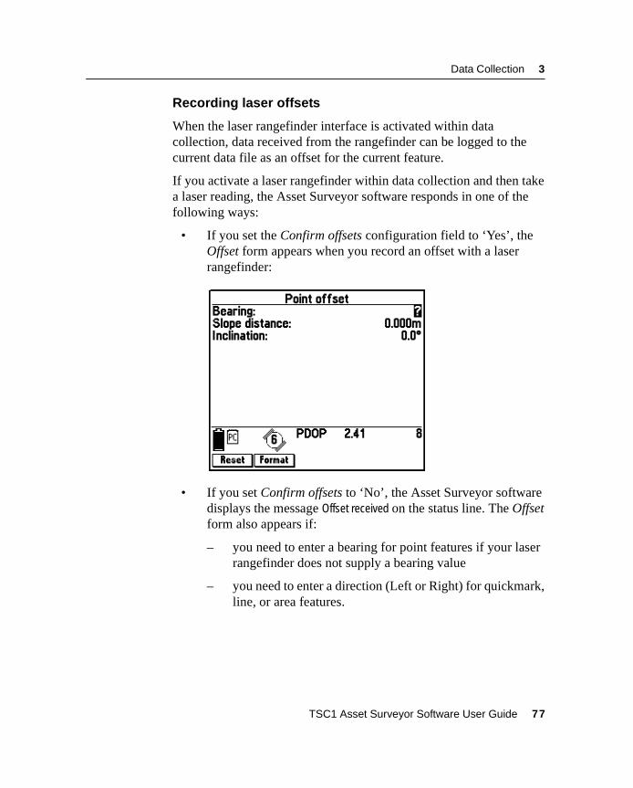
Data Collection 3
Recording laser offsets
When the laser rangefinder interface is activated within datacollection, data received from the rangefinder can be logged to thecurrent data file as an offset for the current feature.
If you activate a laser rangefinder within data collection and then takea laser reading, the Asset Surveyor software responds in one of thefollowing ways:
• If you set the Confirm offsets configuration field to ‘Yes’, theOffset form appears when you record an offset with a laserrangefinder:
• If you set Confirm offsets to ‘No’, the Asset Surveyor softwaredisplays the message Offset received on the status line. The Offsetform also appears if:
– you need to enter a bearing for point features if your laserrangefinder does not supply a bearing value
– you need to enter a direction (Left or Right) for quickmark,line, or area features.
TSC1 Asset Surveyor Software User Guide 77
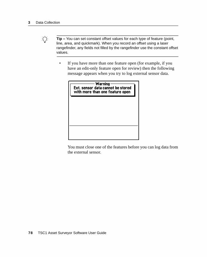
3 Data Collection
B Tip – You can set constant offset values for each type of feature (point,line, area, and quickmark). When you record an offset using a laserrangefinder, any fields not filled by the rangefinder use the constant offsetvalues.
• If you have more than one feature open (for example, if youhave an edit-only feature open for review) then the followingmessage appears when you try to log external sensor data.
You must close one of the features before you can log data fromthe external sensor.
78 TSC1 Asset Surveyor Software User Guide
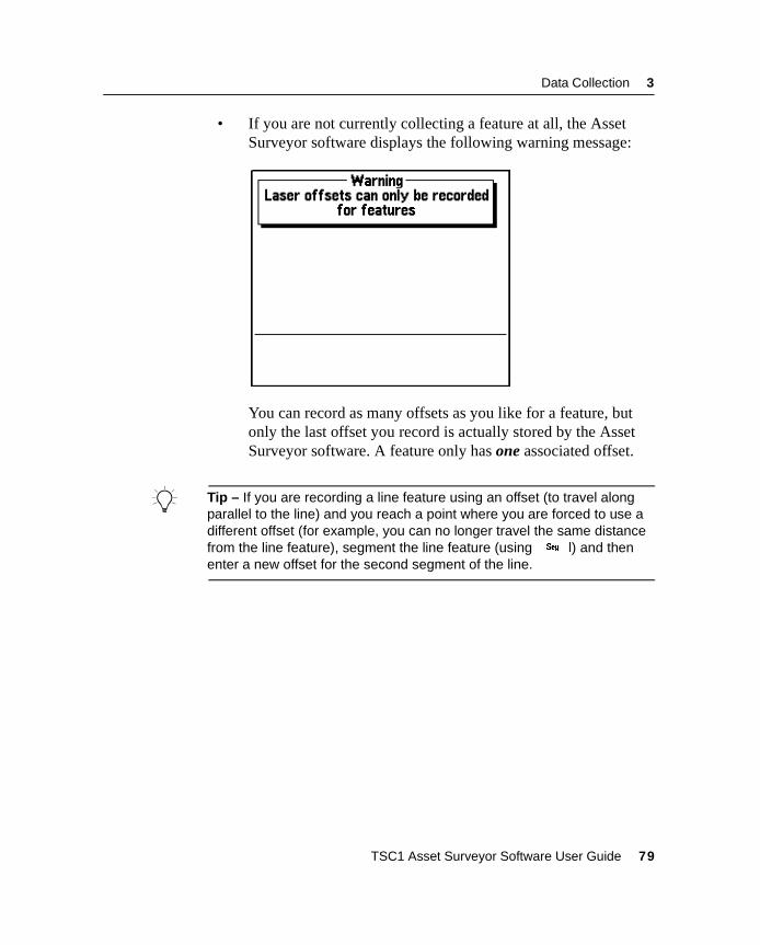
Data Collection 3
• If you are not currently collecting a feature at all, the AssetSurveyor software displays the following warning message:
You can record as many offsets as you like for a feature, butonly the last offset you record is actually stored by the AssetSurveyor software. A feature only has one associated offset.
B Tip – If you are recording a line feature using an offset (to travel alongparallel to the line) and you reach a point where you are forced to use adifferent offset (for example, you can no longer travel the same distancefrom the line feature), segment the line feature (usings) and thenenter a new offset for the second segment of the line.
TSC1 Asset Surveyor Software User Guide 79
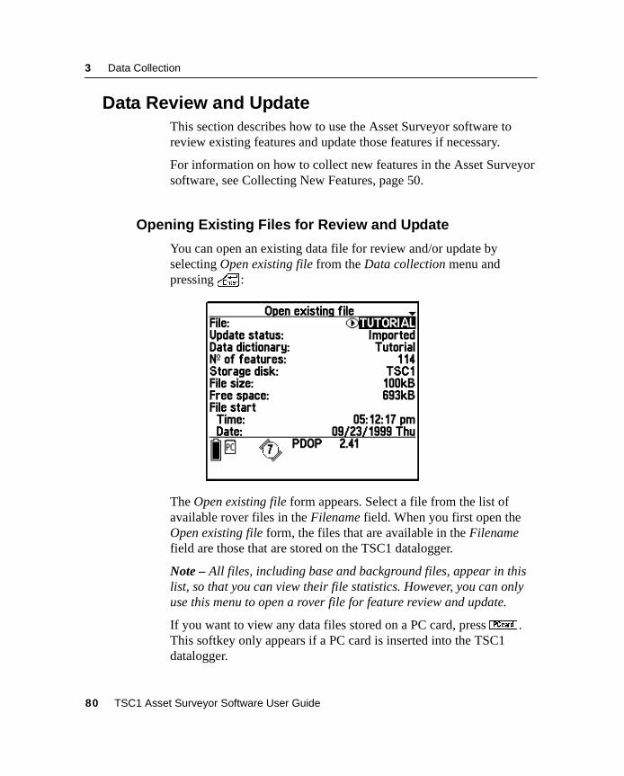
3 Data Collection
3.3 Data Review and UpdateThis section describes how to use the Asset Surveyor software toreview existing features and update those features if necessary.
For information on how to collect new features in the Asset Surveyorsoftware, see Collecting New Features, page 50.
3.3.1 Opening Existing Files for Review and Update
You can open an existing data file for review and/or update byselecting Open existing file from the Data collection menu andpressing\ :
The Open existing file form appears. Select a file from the list ofavailable rover files in the Filename field. When you first open theOpen existing file form, the files that are available in the Filenamefield are those that are stored on the TSC1 datalogger.
Note – All files, including base and background files, appear in thislist, so that you can view their file statistics. However, you can onlyuse this menu to open a rover file for feature review and update.
If you want to view any data files stored on a PC card, pressC .This softkey only appears if a PC card is inserted into the TSC1datalogger.
80 TSC1 Asset Surveyor Software User Guide
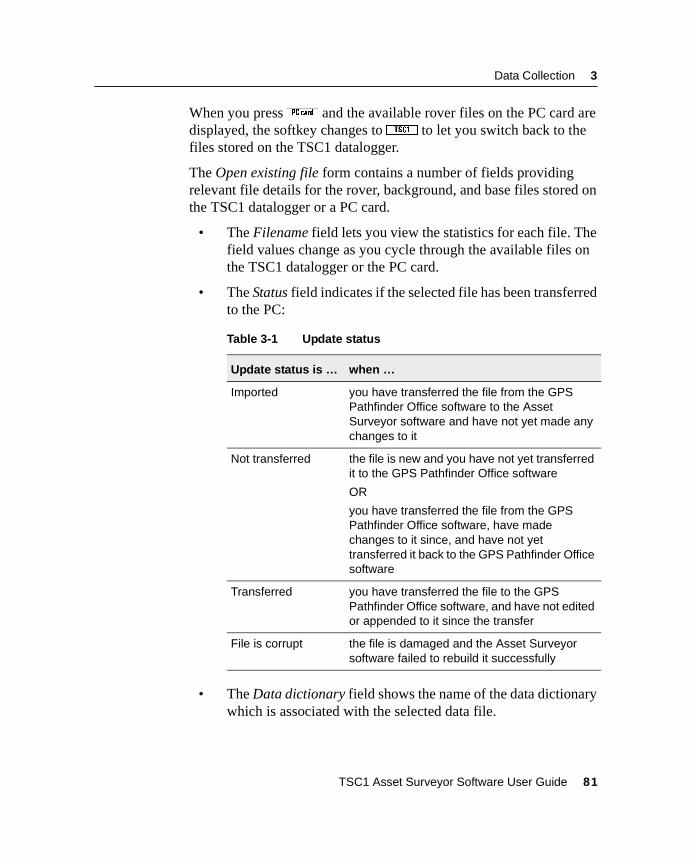
Data Collection 3
When you pressC and the available rover files on the PC card aredisplayed, the softkey changes toc to let you switch back to thefiles stored on the TSC1 datalogger.
The Open existing file form contains a number of fields providingrelevant file details for the rover, background, and base files stored onthe TSC1 datalogger or a PC card.
• The Filename field lets you view the statistics for each file. Thefield values change as you cycle through the available files onthe TSC1 datalogger or the PC card.
• The Status field indicates if the selected file has been transferredto the PC:
• The Data dictionary field shows the name of the data dictionarywhich is associated with the selected data file.
Table 3-1 Update status
Update status is … when …
Imported you have transferred the file from the GPSPathfinder Office software to the AssetSurveyor software and have not yet made anychanges to it
Not transferred the file is new and you have not yet transferredit to the GPS Pathfinder Office software
OR
you have transferred the file from the GPSPathfinder Office software, have madechanges to it since, and have not yettransferred it back to the GPS Pathfinder Officesoftware
Transferred you have transferred the file to the GPSPathfinder Office software, and have not editedor appended to it since the transfer
File is corrupt the file is damaged and the Asset Surveyorsoftware failed to rebuild it successfully
TSC1 Asset Surveyor Software User Guide 81
3 Data Collection
• The No. of features field shows the number of point, line, andarea features in the selected data file.
• The Storage disk field shows the storage location of the file:TSC1 datalogger when the file is stored in the internal memoryof the TSC1 datalogger, or PC Card when the file is on a PCcard.
• The File size field shows the size of this data file in kilobytes.
• The Free space field shows the remaining amount of data space,in kilobytes, either on the TSC1 datalogger or the PC card. Thefield displays as Free space (TSC1) when the selected file isstored on the TSC1 datalogger. It displays as Free space (PCcard) when the selected file is stored on the PC card.
• The File start fields show the time and date when this file wascreated. This may not be the same as the time when the file firsthad data logged to it, but these two events normally occur oneafter the other.
Note – If the file was imported this field will show the currentGPS time until you first log new data to the file. Once you lognew data it shows the date and time you began updating the file.
• The File end fields show the time and date when this file lasthad data logged to it.
In the Filename field, select the file you want to open and press\ .
If the status of the selected file is Not transferred and GPS data in thefile was collected or appended to the file more than seven days ago,the Asset Surveyor software does not let you reopen that file forfurther logging of GPS data. This means that you cannot create newfeatures or update the GPS position of existing ones, although you canreview and edit attribute data and offsets. This restriction is due to atechnical limitation related to the way that GPS times are stored. Inorder to maintain full accuracy of storage, it is necessary to limit thetimespan of a data file to seven days.
82 TSC1 Asset Surveyor Software User Guide
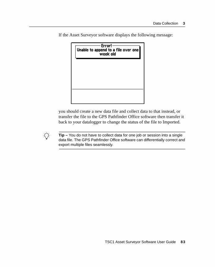
Data Collection 3
If the Asset Surveyor software displays the following message:
you should create a new data file and collect data to that instead, ortransfer the file to the GPS Pathfinder Office software then transfer itback to your datalogger to change the status of the file to Imported.
B Tip – You do not have to collect data for one job or session into a singledata file. The GPS Pathfinder Office software can differentially correct andexport multiple files seamlessly.
TSC1 Asset Surveyor Software User Guide 83
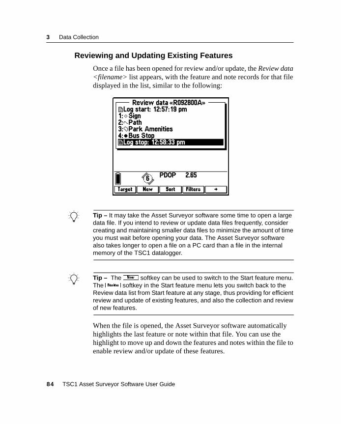
3 Data Collection
3.3.2 Reviewing and Updating Existing Features
Once a file has been opened for review and/or update, the Review data<filename> list appears, with the feature and note records for that filedisplayed in the list, similar to the following:
B Tip – It may take the Asset Surveyor software some time to open a largedata file. If you intend to review or update data files frequently, considercreating and maintaining smaller data files to minimize the amount of timeyou must wait before opening your data. The Asset Surveyor softwarealso takes longer to open a file on a PC card than a file in the internalmemory of the TSC1 datalogger.
B Tip – Theb softkey can be used to switch to the Start feature menu.The{ softkey in the Start feature menu lets you switch back to theReview data list from Start feature at any stage, thus providing for efficientreview and update of existing features, and also the collection and reviewof new features.
When the file is opened, the Asset Surveyor software automaticallyhighlights the last feature or note within that file. You can use thehighlight to move up and down the features and notes within the file toenable review and/or update of these features.
84 TSC1 Asset Surveyor Software User Guide
Data Collection 3
Icons to the left of the file records indicate the nature of the adjacentrecord:
notes
line features
area features
Point features appear with the symbol allocated to their point featuretype for that data dictionary, as configured in the Point feature symbolsform. These point feature symbols are the same as the symbols shownin the Map screen.
Note – For more information on allocating point feature symbols inthe Asset Surveyor software, see Map Display Options, page 239.
When a feature is highlighted, two labels appear below the Reviewdata list, displaying attribute information from the selected feature.Each label consists of the attribute name followed by the attributevalue for this feature.
If the feature has no attributes, or no labels are selected for this featuretype, the Review data list extends down to the status line and no labelinformation appears.
Note – For more information on allocating labels in the AssetSurveyor software, see Map Display Options, page 239.
TSC1 Asset Surveyor Software User Guide 85
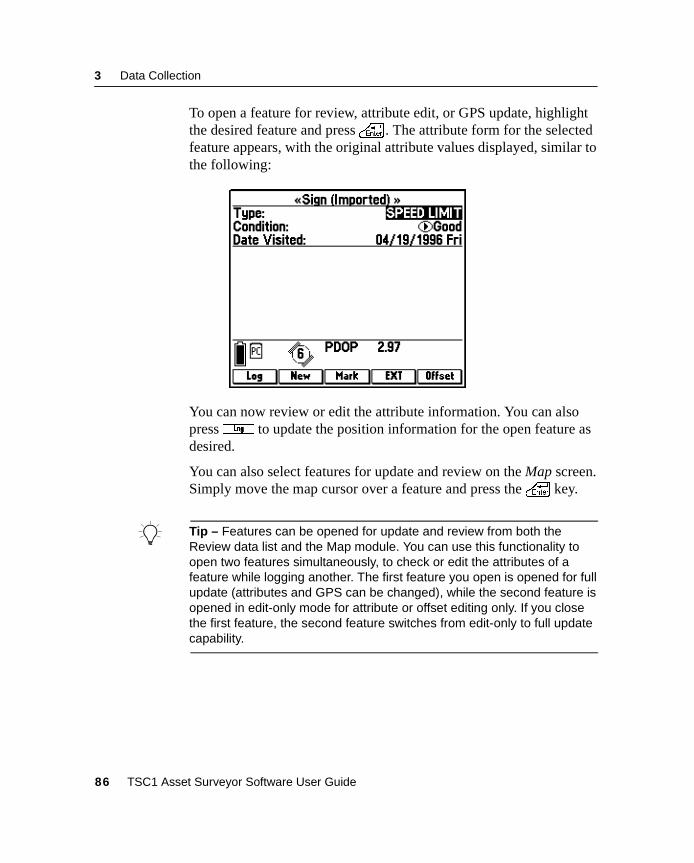
3 Data Collection
To open a feature for review, attribute edit, or GPS update, highlightthe desired feature and press\ . The attribute form for the selectedfeature appears, with the original attribute values displayed, similar tothe following:
You can now review or edit the attribute information. You can alsopress3 to update the position information for the open feature asdesired.
You can also select features for update and review on the Map screen.Simply move the map cursor over a feature and press the\ key.
B Tip – Features can be opened for update and review from both theReview data list and the Map module. You can use this functionality toopen two features simultaneously, to check or edit the attributes of afeature while logging another. The first feature you open is opened for fullupdate (attributes and GPS can be changed), while the second feature isopened in edit-only mode for attribute or offset editing only. If you closethe first feature, the second feature switches from edit-only to full updatecapability.
86 TSC1 Asset Surveyor Software User Guide
Data Collection 3
3.3.3 Reviewing and Updating Attribute Data
The Asset Surveyor software lets you review and edit the attributeinformation for any existing feature. When an existing feature isopened, the attribute values are as they were entered at the time ofcollection, enabling review and edit if necessary. To review theattributes for a feature, highlight it on the Review data list and press\ . To edit the attributes simply change them to the new value. Youcan close the feature without saving any changes to the feature bypressing= . This closes the form and returns you to the Review datalist. To edit the feature’s attribute information just change any of theattribute values, then press\ to save the changes to the file.
Note – When you update attributes, the original attribute values of afeature are only discarded once the feature is closed and the newattribute values are saved to the file. If the feature update is cancelledby pressing= , any changes are discarded and the original attributevalues are restored to the feature.
For further details on entering feature attribute values, see EnteringAttribute Values, page 58.
3.3.4 Updating Offsets
You can update a feature’s offset before, during, or after GPS update.After locating the feature in the Review data list or the map, andpressing\ to display its attributes, pressO to open the offsetform for this feature type. Edit offset values as usual, then press\to close the offset form and press\ again to confirm your changesand close the feature.
You can also edit offsets from the feature’s Position Information form.In the Review data list, select the feature, pressQ , then pressO .
TSC1 Asset Surveyor Software User Guide 87
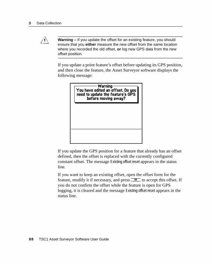
3 Data Collection
C Warning – If you update the offset for an existing feature, you shouldensure that you either measure the new offset from the same locationwhere you recorded the old offset, or log new GPS data from the newoffset position.
If you update a point feature’s offset before updating its GPS position,and then close the feature, the Asset Surveyor software displays thefollowing message:
If you update the GPS position for a feature that already has an offsetdefined, then the offset is replaced with the currently configuredconstant offset. The message Existing offset reset appears in the statusline.
If you want to keep an existing offset, open the offset form for thefeature, modify it if necessary, and pressP to accept this offset. Ifyou do not confirm the offset while the feature is open for GPSlogging, it is cleared and the message Existing offset reset appears in thestatus line.
88 TSC1 Asset Surveyor Software User Guide
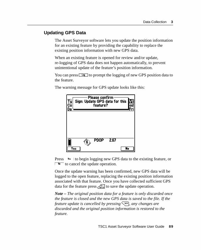
Data Collection 3
3.3.5 Updating GPS Data
The Asset Surveyor software lets you update the position informationfor an existing feature by providing the capability to replace theexisting position information with new GPS data.
When an existing feature is opened for review and/or update,re-logging of GPS data does not happen automatically, to preventunintentional update of the feature’s position information.
You can press3 to prompt the logging of new GPS position data tothe feature.
The warning message for GPS update looks like this:
Pressy to begin logging new GPS data to the existing feature, orn to cancel the update operation.
Once the update warning has been confirmed, new GPS data will belogged to the open feature, replacing the existing position informationassociated with that feature. Once you have collected sufficient GPSdata for the feature press\ to save the update operation.
Note – The original position data for a feature is only discarded oncethe feature is closed and the new GPS data is saved to the file. If thefeature update is cancelled by pressing= , any changes arediscarded and the original position information is restored to thefeature.
TSC1 Asset Surveyor Software User Guide 89
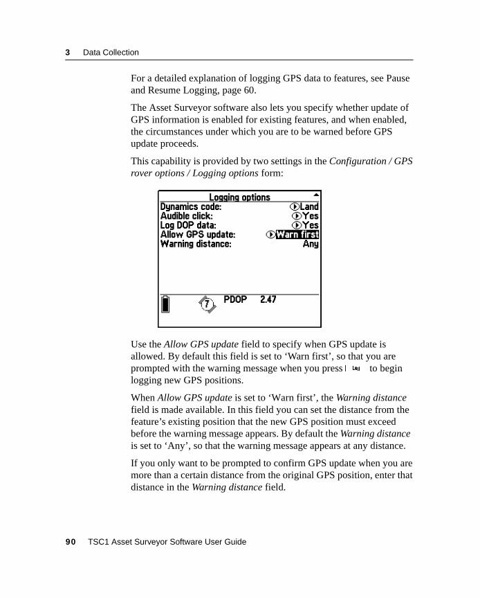
3 Data Collection
For a detailed explanation of logging GPS data to features, see Pauseand Resume Logging, page 60.
The Asset Surveyor software also lets you specify whether update ofGPS information is enabled for existing features, and when enabled,the circumstances under which you are to be warned before GPSupdate proceeds.
This capability is provided by two settings in the Configuration / GPSrover options / Logging options form:
Use the Allow GPS update field to specify when GPS update isallowed. By default this field is set to ‘Warn first’, so that you areprompted with the warning message when you press3 to beginlogging new GPS positions.
When Allow GPS update is set to ‘Warn first’, the Warning distancefield is made available. In this field you can set the distance from thefeature’s existing position that the new GPS position must exceedbefore the warning message appears. By default the Warning distanceis set to ‘Any’, so that the warning message appears at any distance.
If you only want to be prompted to confirm GPS update when you aremore than a certain distance from the original GPS position, enter thatdistance in the Warning distance field.
90 TSC1 Asset Surveyor Software User Guide
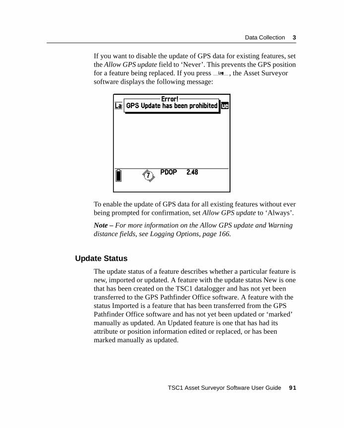
Data Collection 3
If you want to disable the update of GPS data for existing features, setthe Allow GPS update field to ‘Never’. This prevents the GPS positionfor a feature being replaced. If you press3 , the Asset Surveyorsoftware displays the following message:
To enable the update of GPS data for all existing features without everbeing prompted for confirmation, set Allow GPS update to ‘Always’.
Note – For more information on the Allow GPS update and Warningdistance fields, see Logging Options, page 166.
3.3.6 Update Status
The update status of a feature describes whether a particular feature isnew, imported or updated. A feature with the update status New is onethat has been created on the TSC1 datalogger and has not yet beentransferred to the GPS Pathfinder Office software. A feature with thestatus Imported is a feature that has been transferred from the GPSPathfinder Office software and has not yet been updated or ‘marked’manually as updated. An Updated feature is one that has had itsattribute or position information edited or replaced, or has beenmarked manually as updated.
TSC1 Asset Surveyor Software User Guide 91
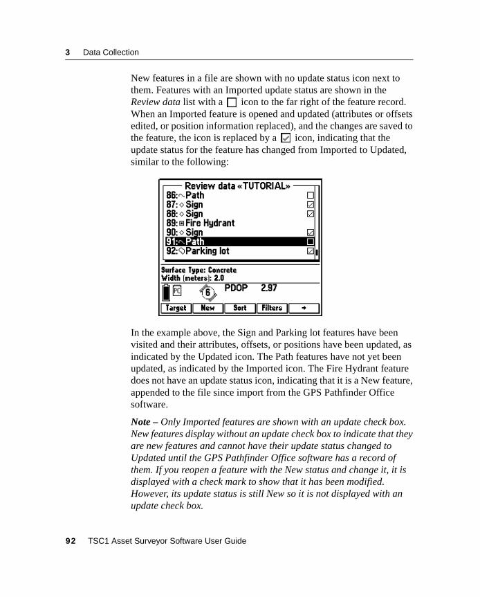
3 Data Collection
New features in a file are shown with no update status icon next tothem. Features with an Imported update status are shown in theReview data list with a icon to the far right of the feature record.When an Imported feature is opened and updated (attributes or offsetsedited, or position information replaced), and the changes are saved tothe feature, the icon is replaced by a icon, indicating that theupdate status for the feature has changed from Imported to Updated,similar to the following:
In the example above, the Sign and Parking lot features have beenvisited and their attributes, offsets, or positions have been updated, asindicated by the Updated icon. The Path features have not yet beenupdated, as indicated by the Imported icon. The Fire Hydrant featuredoes not have an update status icon, indicating that it is a New feature,appended to the file since import from the GPS Pathfinder Officesoftware.
Note – Only Imported features are shown with an update check box.New features display without an update check box to indicate that theyare new features and cannot have their update status changed toUpdated until the GPS Pathfinder Office software has a record ofthem. If you reopen a feature with the New status and change it, it isdisplayed with a check mark to show that it has been modified.However, its update status is still New so it is not displayed with anupdate check box.
92 TSC1 Asset Surveyor Software User Guide
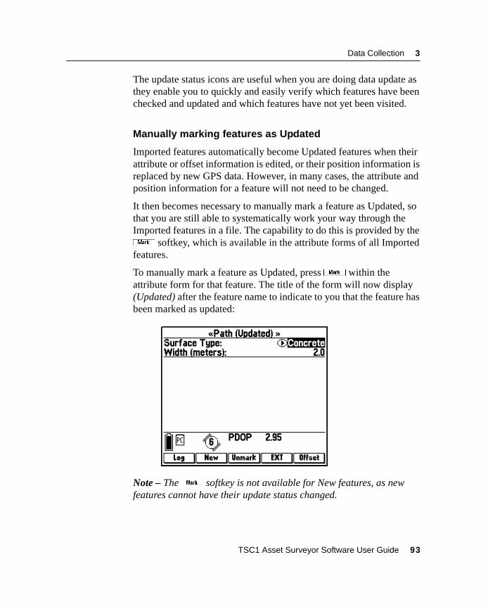
Data Collection 3
The update status icons are useful when you are doing data update asthey enable you to quickly and easily verify which features have beenchecked and updated and which features have not yet been visited.
Manually marking features as Updated
Imported features automatically become Updated features when theirattribute or offset information is edited, or their position information isreplaced by new GPS data. However, in many cases, the attribute andposition information for a feature will not need to be changed.
It then becomes necessary to manually mark a feature as Updated, sothat you are still able to systematically work your way through theImported features in a file. The capability to do this is provided by the( softkey, which is available in the attribute forms of all Importedfeatures.
To manually mark a feature as Updated, press( within theattribute form for that feature. The title of the form will now display(Updated) after the feature name to indicate to you that the feature hasbeen marked as updated:
Note – The( softkey is not available for New features, as newfeatures cannot have their update status changed.
TSC1 Asset Surveyor Software User Guide 93
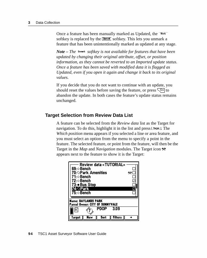
3 Data Collection
Once a feature has been manually marked as Updated, the(softkey is replaced by the) softkey. This lets you unmark afeature that has been unintentionally marked as updated at any stage.
Note – The) softkey is not available for features that have beenupdated by changing their original attribute, offset, or positioninformation, as they cannot be reverted to an Imported update status.Once a feature has been saved with modified data it is flagged asUpdated, even if you open it again and change it back to its originalvalues.
If you decide that you do not want to continue with an update, youshould reset the values before saving the feature, or press= toabandon the update. In both cases the feature’s update status remainsunchanged.
3.3.7 Target Selection from Review Data List
A feature can be selected from the Review data list as the Target fornavigation. To do this, highlight it in the list and pressG. TheWhich position menu appears if you selected a line or area feature, andyou must select an option from the menu to specify a point in thefeature. The selected feature, or point from the feature, will then be theTarget in the Map and Navigation modules. The Target iconappears next to the feature to show it is the Target:
94 TSC1 Asset Surveyor Software User Guide
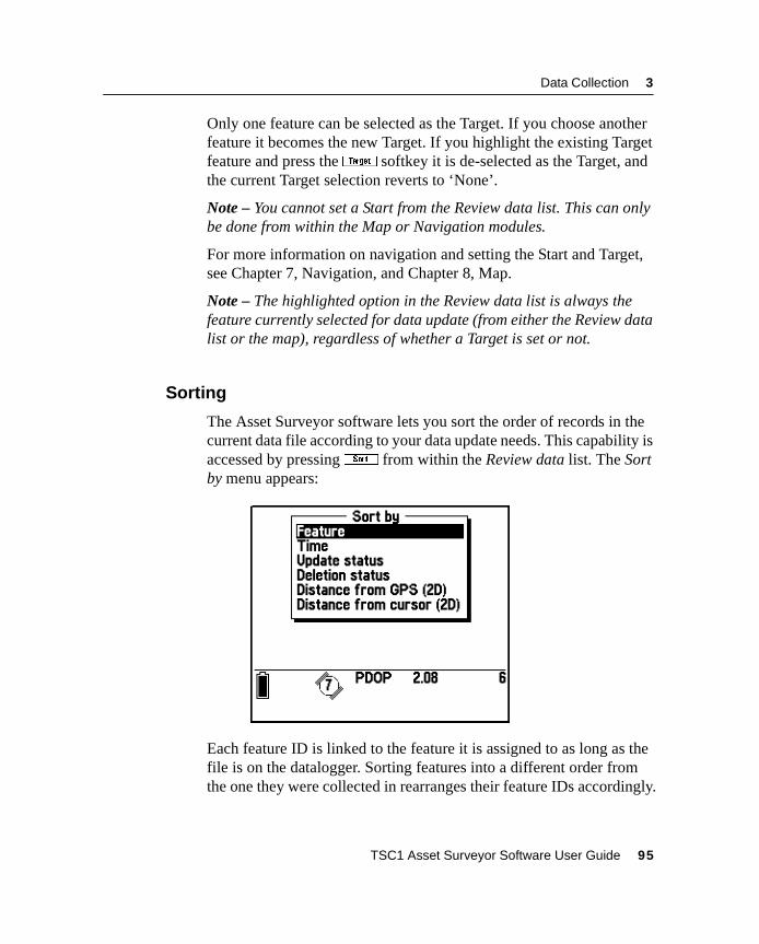
Data Collection 3
Only one feature can be selected as the Target. If you choose anotherfeature it becomes the new Target. If you highlight the existing Targetfeature and press theG softkey it is de-selected as the Target, andthe current Target selection reverts to ‘None’.
Note – You cannot set a Start from the Review data list. This can onlybe done from within the Map or Navigation modules.
For more information on navigation and setting the Start and Target,see Chapter 7, Navigation, and Chapter 8, Map.
Note – The highlighted option in the Review data list is always thefeature currently selected for data update (from either the Review datalist or the map), regardless of whether a Target is set or not.
3.3.8 Sorting
The Asset Surveyor software lets you sort the order of records in thecurrent data file according to your data update needs. This capability isaccessed by pressing# from within the Review data list. The Sortby menu appears:
Each feature ID is linked to the feature it is assigned to as long as thefile is on the datalogger. Sorting features into a different order fromthe one they were collected in rearranges their feature IDs accordingly.
TSC1 Asset Surveyor Software User Guide 95
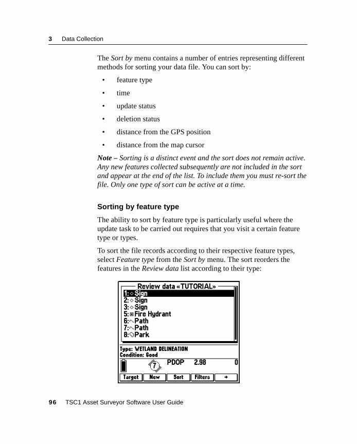
3 Data Collection
The Sort by menu contains a number of entries representing differentmethods for sorting your data file. You can sort by:
• feature type
• time
• update status
• deletion status
• distance from the GPS position
• distance from the map cursor
Note – Sorting is a distinct event and the sort does not remain active.Any new features collected subsequently are not included in the sortand appear at the end of the list. To include them you must re-sort thefile. Only one type of sort can be active at a time.
Sorting by feature type
The ability to sort by feature type is particularly useful where theupdate task to be carried out requires that you visit a certain featuretype or types.
To sort the file records according to their respective feature types,select Feature type from the Sort by menu. The sort reorders thefeatures in the Review data list according to their type:
96 TSC1 Asset Surveyor Software User Guide
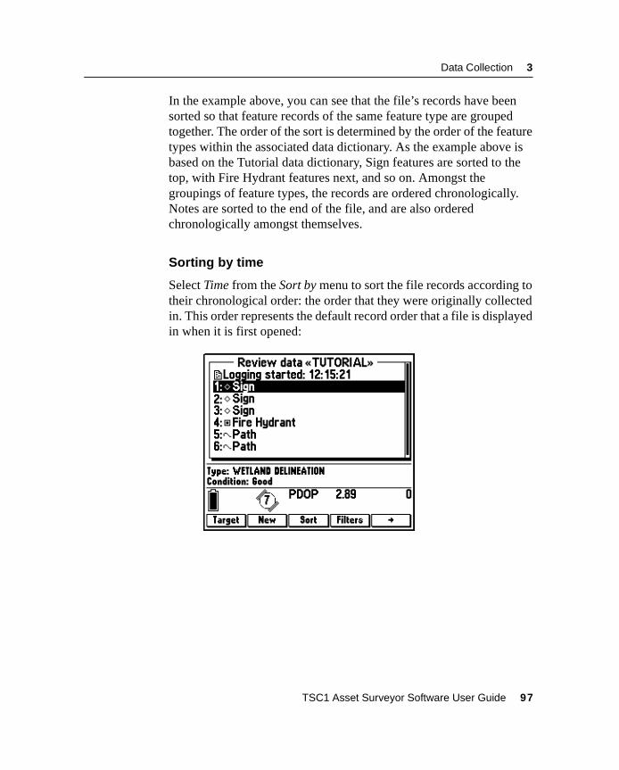
Data Collection 3
In the example above, you can see that the file’s records have beensorted so that feature records of the same feature type are groupedtogether. The order of the sort is determined by the order of the featuretypes within the associated data dictionary. As the example above isbased on the Tutorial data dictionary, Sign features are sorted to thetop, with Fire Hydrant features next, and so on. Amongst thegroupings of feature types, the records are ordered chronologically.Notes are sorted to the end of the file, and are also orderedchronologically amongst themselves.
Sorting by time
Select Time from the Sort by menu to sort the file records according totheir chronological order: the order that they were originally collectedin. This order represents the default record order that a file is displayedin when it is first opened:
TSC1 Asset Surveyor Software User Guide 97
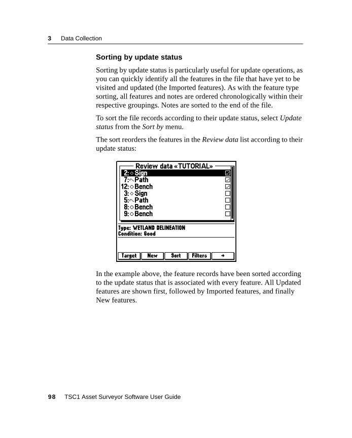
3 Data Collection
Sorting by update status
Sorting by update status is particularly useful for update operations, asyou can quickly identify all the features in the file that have yet to bevisited and updated (the Imported features). As with the feature typesorting, all features and notes are ordered chronologically within theirrespective groupings. Notes are sorted to the end of the file.
To sort the file records according to their update status, select Updatestatus from the Sort by menu.
The sort reorders the features in the Review data list according to theirupdate status:
In the example above, the feature records have been sorted accordingto the update status that is associated with every feature. All Updatedfeatures are shown first, followed by Imported features, and finallyNew features.
98 TSC1 Asset Surveyor Software User Guide
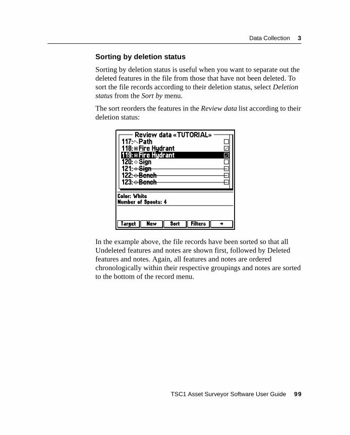
Data Collection 3
Sorting by deletion status
Sorting by deletion status is useful when you want to separate out thedeleted features in the file from those that have not been deleted. Tosort the file records according to their deletion status, select Deletionstatus from the Sort by menu.
The sort reorders the features in the Review data list according to theirdeletion status:
In the example above, the file records have been sorted so that allUndeleted features and notes are shown first, followed by Deletedfeatures and notes. Again, all features and notes are orderedchronologically within their respective groupings and notes are sortedto the bottom of the record menu.
TSC1 Asset Surveyor Software User Guide 99
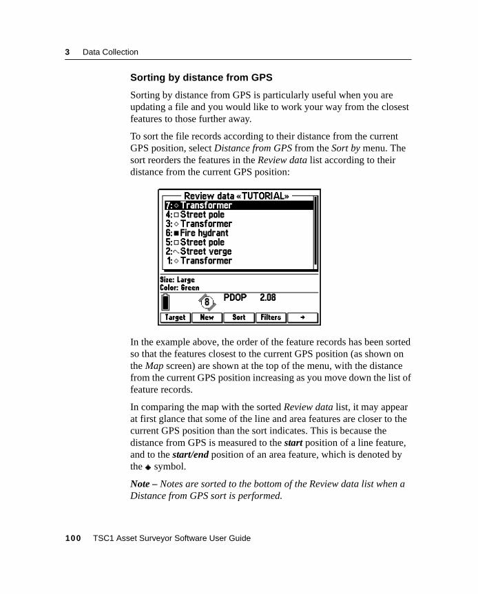
3 Data Collection
Sorting by distance from GPS
Sorting by distance from GPS is particularly useful when you areupdating a file and you would like to work your way from the closestfeatures to those further away.
To sort the file records according to their distance from the currentGPS position, select Distance from GPS from the Sort by menu. Thesort reorders the features in the Review data list according to theirdistance from the current GPS position:
In the example above, the order of the feature records has been sortedso that the features closest to the current GPS position (as shown onthe Map screen) are shown at the top of the menu, with the distancefrom the current GPS position increasing as you move down the list offeature records.
In comparing the map with the sorted Review data list, it may appearat first glance that some of the line and area features are closer to thecurrent GPS position than the sort indicates. This is because thedistance from GPS is measured to the start position of a line feature,and to the start/end position of an area feature, which is denoted bythe symbol.
Note – Notes are sorted to the bottom of the Review data list when aDistance from GPS sort is performed.
100 TSC1 Asset Surveyor Software User Guide
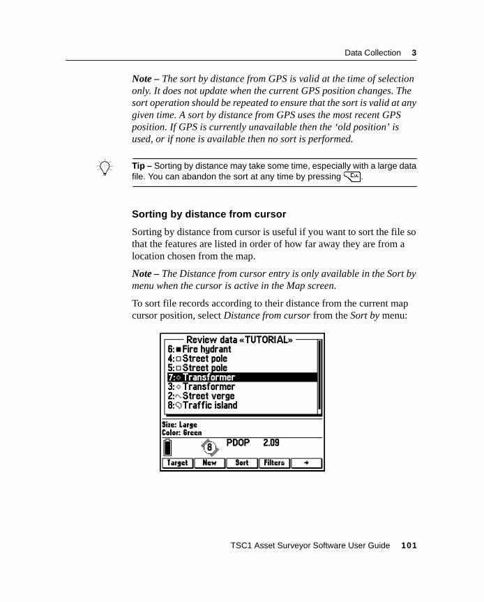
Data Collection 3
Note – The sort by distance from GPS is valid at the time of selectiononly. It does not update when the current GPS position changes. Thesort operation should be repeated to ensure that the sort is valid at anygiven time. A sort by distance from GPS uses the most recent GPSposition. If GPS is currently unavailable then the ‘old position’ isused, or if none is available then no sort is performed.
B Tip – Sorting by distance may take some time, especially with a large datafile. You can abandon the sort at any time by pressing=.
Sorting by distance from cursor
Sorting by distance from cursor is useful if you want to sort the file sothat the features are listed in order of how far away they are from alocation chosen from the map.
Note – The Distance from cursor entry is only available in the Sort bymenu when the cursor is active in the Map screen.
To sort file records according to their distance from the current mapcursor position, select Distance from cursor from the Sort by menu:
TSC1 Asset Surveyor Software User Guide 101
3 Data Collection
In the example above, the file has been sorted so that the featuresclosest to the current cursor position (as shown on the Map screen) areshown at the start of the list, with the distance from the current cursorposition increasing as you move down the list. As with the Distancefrom GPS, the Distance from cursor is measured to the start positionof line features and to the start/end position of area features.
Note – Notes are sorted to the bottom of the Review data list when aDistance from cursor sort is performed.
Note – The sort by distance from cursor is valid at the time of selectiononly. It does not update when the current cursor position changes. Thesort operation should be repeated to ensure that the sort is valid at anygiven time. A sort by distance from cursor uses the current location ofthe map cursor, the precision of which may be affected by the currentzoom scale.
B Tip – Sorting by distance may take some time, especially with a large datafile. You can abandon the sort at any time by pressing=.
3.3.9 Filtering
Filtering lets you show or hide different features from the feature list.This is useful for showing only specific sets of features that you areinterested in and to hide others, removing features that you are notinterested in from the Review data list and the Map screen. It isespecially useful if you have a large list with many different featuretypes.
You can use filtering to show only specific types of features you areinterested in (for example, all features that still need to be updated) orto hide features that you do not need to see so that the map display orReview data list is less cluttered.
Multiple filters can be applied sequentially. For example, a file can befiltered by feature type and time to show a particular feature typerecorded within a certain time frame.
102 TSC1 Asset Surveyor Software User Guide
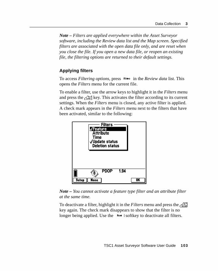
Data Collection 3
Note – Filters are applied everywhere within the Asset Surveyorsoftware, including the Review data list and the Map screen. Specifiedfilters are associated with the open data file only, and are reset whenyou close the file. If you open a new data file, or reopen an existingfile, the filtering options are returned to their default settings.
Applying filters
To access Filtering options, press^ in the Review data list. Thisopens the Filters menu for the current file.
To enable a filter, use the arrow keys to highlight it in the Filters menuand press the\ key. This activates the filter according to its currentsettings. When the Filters menu is closed, any active filter is applied.A check mark appears in the Filters menu next to the filters that havebeen activated, similar to the following:
Note – You cannot activate a feature type filter and an attribute filterat the same time.
To deactivate a filter, highlight it in the Filters menu and press the\key again. The check mark disappears to show that the filter is nolonger being applied. Use the7 softkey to deactivate all filters.
TSC1 Asset Surveyor Software User Guide 103
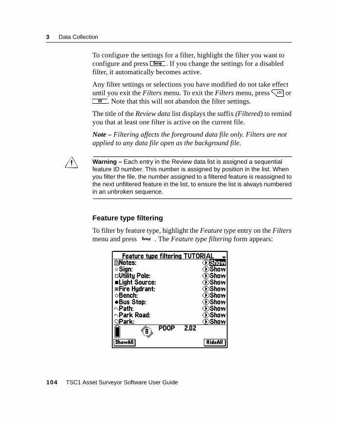
3 Data Collection
To configure the settings for a filter, highlight the filter you want toconfigure and pressS . If you change the settings for a disabledfilter, it automatically becomes active.
Any filter settings or selections you have modified do not take effectuntil you exit the Filters menu. To exit the Filters menu, press= orP. Note that this will not abandon the filter settings.
The title of the Review data list displays the suffix (Filtered) to remindyou that at least one filter is active on the current file.
Note – Filtering affects the foreground data file only. Filters are notapplied to any data file open as the background file.
C Warning – Each entry in the Review data list is assigned a sequentialfeature ID number. This number is assigned by position in the list. Whenyou filter the file, the number assigned to a filtered feature is reassigned tothe next unfiltered feature in the list, to ensure the list is always numberedin an unbroken sequence.
Feature type filtering
To filter by feature type, highlight the Feature type entry on the Filtersmenu and pressS . The Feature type filtering form appears:
104 TSC1 Asset Surveyor Software User Guide
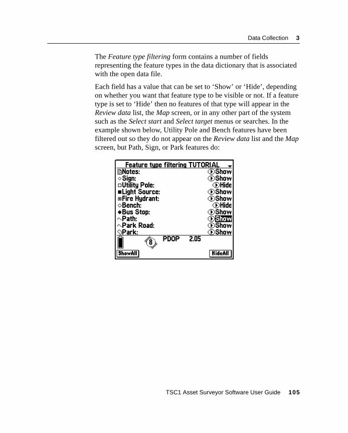
Data Collection 3
The Feature type filtering form contains a number of fieldsrepresenting the feature types in the data dictionary that is associatedwith the open data file.
Each field has a value that can be set to ‘Show’ or ‘Hide’, dependingon whether you want that feature type to be visible or not. If a featuretype is set to ‘Hide’ then no features of that type will appear in theReview data list, the Map screen, or in any other part of the systemsuch as the Select start and Select target menus or searches. In theexample shown below, Utility Pole and Bench features have beenfiltered out so they do not appear on the Review data list and the Mapscreen, but Path, Sign, or Park features do:
TSC1 Asset Surveyor Software User Guide 105
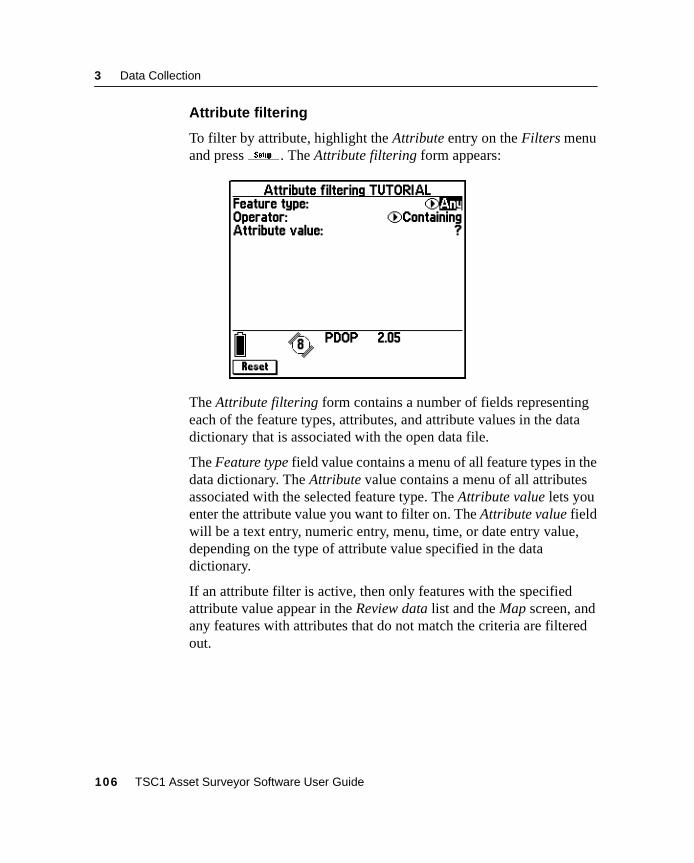
3 Data Collection
Attribute filtering
To filter by attribute, highlight the Attribute entry on the Filters menuand pressS . The Attribute filtering form appears:
The Attribute filtering form contains a number of fields representingeach of the feature types, attributes, and attribute values in the datadictionary that is associated with the open data file.
The Feature type field value contains a menu of all feature types in thedata dictionary. The Attribute value contains a menu of all attributesassociated with the selected feature type. The Attribute value lets youenter the attribute value you want to filter on. The Attribute value fieldwill be a text entry, numeric entry, menu, time, or date entry value,depending on the type of attribute value specified in the datadictionary.
If an attribute filter is active, then only features with the specifiedattribute value appear in the Review data list and the Map screen, andany features with attributes that do not match the criteria are filteredout.
106 TSC1 Asset Surveyor Software User Guide
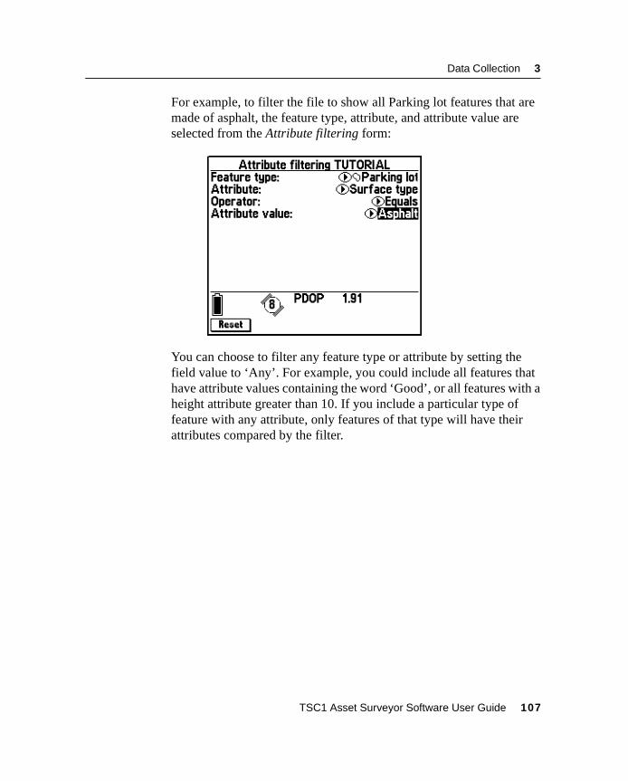
Data Collection 3
For example, to filter the file to show all Parking lot features that aremade of asphalt, the feature type, attribute, and attribute value areselected from the Attribute filtering form:
You can choose to filter any feature type or attribute by setting thefield value to ‘Any’. For example, you could include all features thathave attribute values containing the word ‘Good’, or all features with aheight attribute greater than 10. If you include a particular type offeature with any attribute, only features of that type will have theirattributes compared by the filter.
TSC1 Asset Surveyor Software User Guide 107
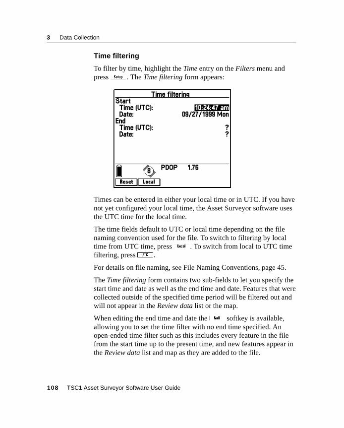
3 Data Collection
Time filtering
To filter by time, highlight the Time entry on the Filters menu andpressS . The Time filtering form appears:
Times can be entered in either your local time or in UTC. If you havenot yet configured your local time, the Asset Surveyor software usesthe UTC time for the local time.
The time fields default to UTC or local time depending on the filenaming convention used for the file. To switch to filtering by localtime from UTC time, press! . To switch from local to UTC timefiltering, press; .
For details on file naming, see File Naming Conventions, page 45.
The Time filtering form contains two sub-fields to let you specify thestart time and date as well as the end time and date. Features that werecollected outside of the specified time period will be filtered out andwill not appear in the Review data list or the map.
When editing the end time and date thel softkey is available,allowing you to set the time filter with no end time specified. Anopen-ended time filter such as this includes every feature in the filefrom the start time up to the present time, and new features appear inthe Review data list and map as they are added to the file.
108 TSC1 Asset Surveyor Software User Guide
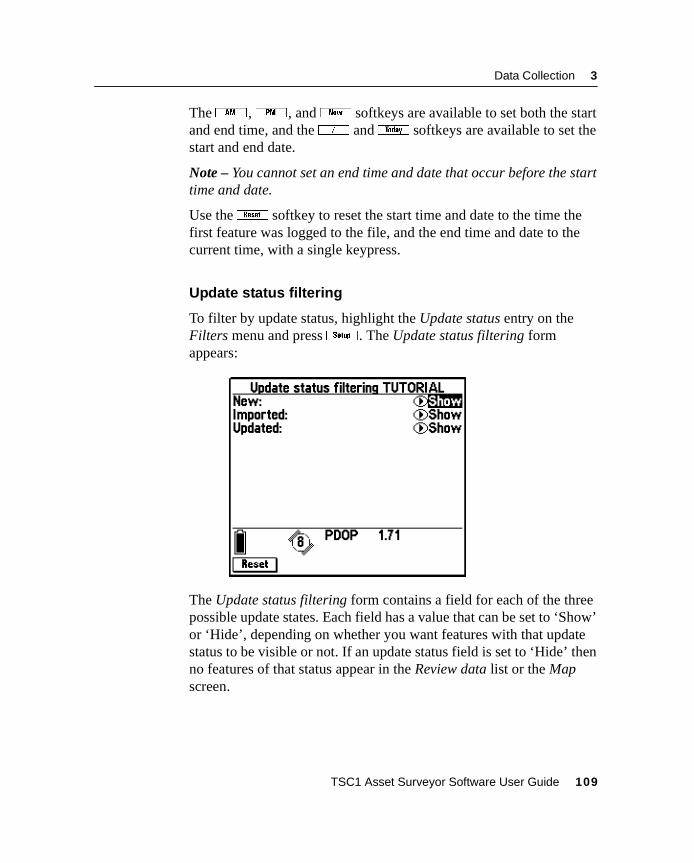
Data Collection 3
The4 ,5 , and8 softkeys are available to set both the startand end time, and the/ andH softkeys are available to set thestart and end date.
Note – You cannot set an end time and date that occur before the starttime and date.
Use theK softkey to reset the start time and date to the time thefirst feature was logged to the file, and the end time and date to thecurrent time, with a single keypress.
Update status filtering
To filter by update status, highlight the Update status entry on theFilters menu and pressS . The Update status filtering formappears:
The Update status filtering form contains a field for each of the threepossible update states. Each field has a value that can be set to ‘Show’or ‘Hide’, depending on whether you want features with that updatestatus to be visible or not. If an update status field is set to ‘Hide’ thenno features of that status appear in the Review data list or the Mapscreen.
TSC1 Asset Surveyor Software User Guide 109
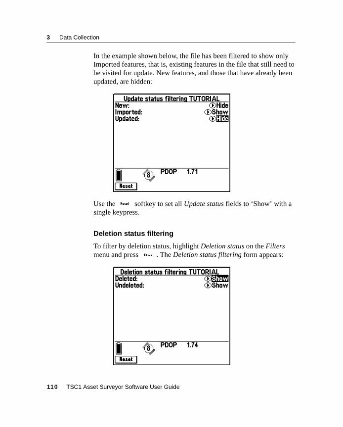
3 Data Collection
In the example shown below, the file has been filtered to show onlyImported features, that is, existing features in the file that still need tobe visited for update. New features, and those that have already beenupdated, are hidden:
Use theK softkey to set all Update status fields to ‘Show’ with asingle keypress.
Deletion status filtering
To filter by deletion status, highlight Deletion status on the Filtersmenu and pressS . The Deletion status filtering form appears:
110 TSC1 Asset Surveyor Software User Guide
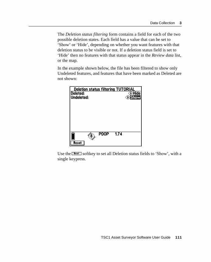
Data Collection 3
The Deletion status filtering form contains a field for each of the twopossible deletion states. Each field has a value that can be set to‘Show’ or ‘Hide’, depending on whether you want features with thatdeletion status to be visible or not. If a deletion status field is set to‘Hide’ then no features with that status appear in the Review data list,or the map.
In the example shown below, the file has been filtered to show onlyUndeleted features, and features that have been marked as Deleted arenot shown:
Use theK softkey to set all Deletion status fields to ‘Show’, with asingle keypress.
TSC1 Asset Surveyor Software User Guide 111
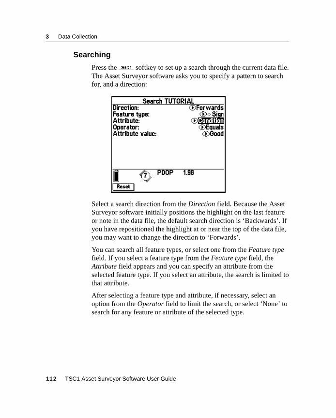
3 Data Collection
3.3.10 Searching
Press thez softkey to set up a search through the current data file.The Asset Surveyor software asks you to specify a pattern to searchfor, and a direction:
Select a search direction from the Direction field. Because the AssetSurveyor software initially positions the highlight on the last featureor note in the data file, the default search direction is ‘Backwards’. Ifyou have repositioned the highlight at or near the top of the data file,you may want to change the direction to ‘Forwards’.
You can search all feature types, or select one from the Feature typefield. If you select a feature type from the Feature type field, theAttribute field appears and you can specify an attribute from theselected feature type. If you select an attribute, the search is limited tothat attribute.
After selecting a feature type and attribute, if necessary, select anoption from the Operator field to limit the search, or select ‘None’ tosearch for any feature or attribute of the selected type.
112 TSC1 Asset Surveyor Software User Guide
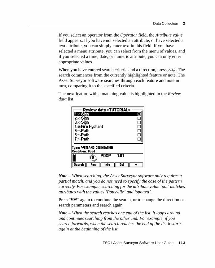
Data Collection 3
If you select an operator from the Operator field, the Attribute valuefield appears. If you have not selected an attribute, or have selected atext attribute, you can simply enter text in this field. If you haveselected a menu attribute, you can select from the menu of values, andif you selected a time, date, or numeric attribute, you can only enterappropriate values.
When you have entered search criteria and a direction, press\ . Thesearch commences from the currently highlighted feature or note. TheAsset Surveyor software searches through each feature and note inturn, comparing it to the specified criteria.
The next feature with a matching value is highlighted in the Reviewdata list:
Note – When searching, the Asset Surveyor software only requires apartial match, and you do not need to specify the case of the patterncorrectly. For example, searching for the attribute value ‘pot’ matchesattributes with the values ‘Pottsville’ and ‘spotted’.
Pressz again to continue the search, or to change the direction orsearch parameters and search again.
Note – When the search reaches one end of the list, it loops aroundand continues searching from the other end. For example, if yousearch forwards, when the search reaches the end of the list it startsagain at the beginning of the list.
TSC1 Asset Surveyor Software User Guide 113
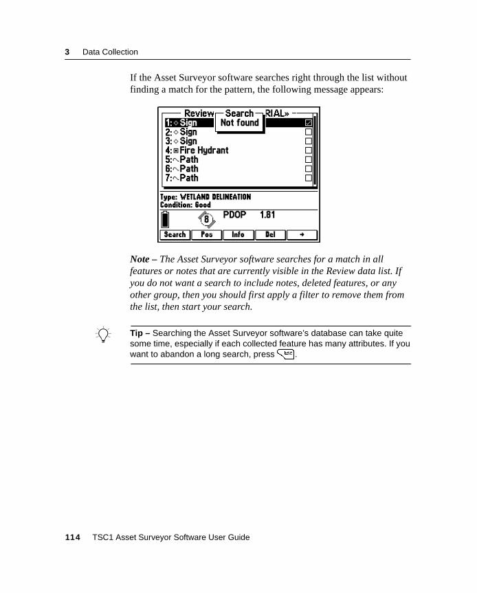
3 Data Collection
If the Asset Surveyor software searches right through the list withoutfinding a match for the pattern, the following message appears:
Note – The Asset Surveyor software searches for a match in allfeatures or notes that are currently visible in the Review data list. Ifyou do not want a search to include notes, deleted features, or anyother group, then you should first apply a filter to remove them fromthe list, then start your search.
B Tip – Searching the Asset Surveyor software’s database can take quitesome time, especially if each collected feature has many attributes. If youwant to abandon a long search, press= .
114 TSC1 Asset Surveyor Software User Guide
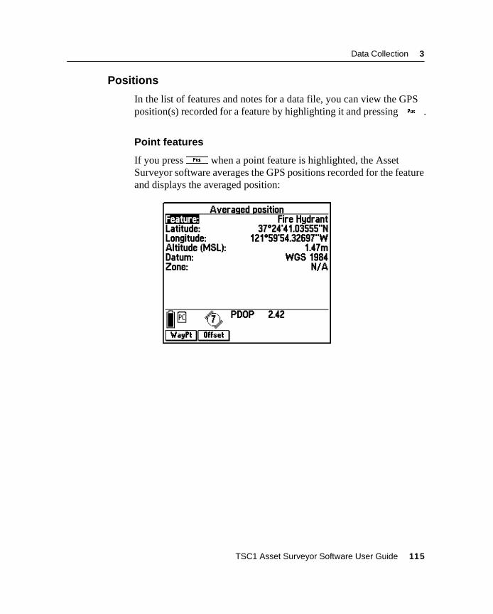
Data Collection 3
3.3.11 Positions
In the list of features and notes for a data file, you can view the GPSposition(s) recorded for a feature by highlighting it and pressingQ .
Point features
If you pressQ when a point feature is highlighted, the AssetSurveyor software averages the GPS positions recorded for the featureand displays the averaged position:
TSC1 Asset Surveyor Software User Guide 115
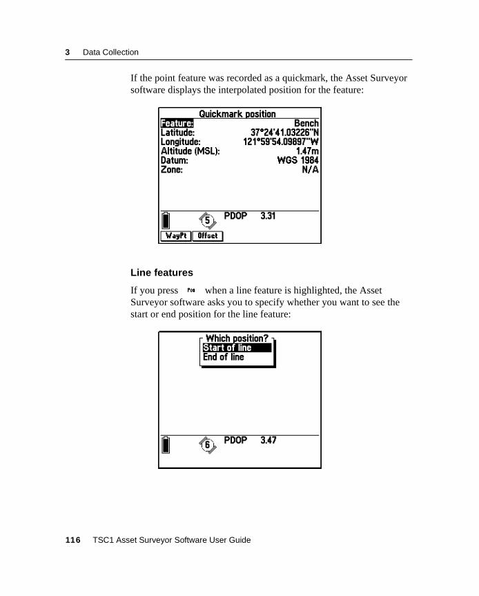
3 Data Collection
If the point feature was recorded as a quickmark, the Asset Surveyorsoftware displays the interpolated position for the feature:
Line features
If you pressQ when a line feature is highlighted, the AssetSurveyor software asks you to specify whether you want to see thestart or end position for the line feature:
116 TSC1 Asset Surveyor Software User Guide
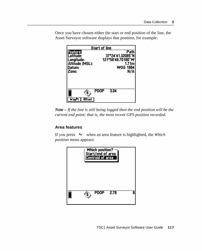
Data Collection 3
Once you have chosen either the start or end position of the line, theAsset Surveyor software displays that position, for example:
Note – If the line is still being logged then the end position will be thecurrent end point; that is, the most recent GPS position recorded.
Area features
If you pressQ when an area feature is highlighted, the Whichposition menu appears:
TSC1 Asset Surveyor Software User Guide 117
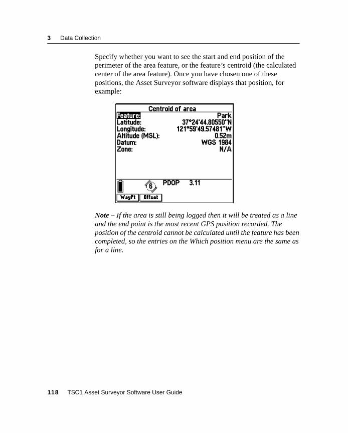
3 Data Collection
Specify whether you want to see the start and end position of theperimeter of the area feature, or the feature’s centroid (the calculatedcenter of the area feature). Once you have chosen one of thesepositions, the Asset Surveyor software displays that position, forexample:
Note – If the area is still being logged then it will be treated as a lineand the end point is the most recent GPS position recorded. Theposition of the centroid cannot be calculated until the feature has beencompleted, so the entries on the Which position menu are the same asfor a line.
118 TSC1 Asset Surveyor Software User Guide

Data Collection 3
Creating waypoints from features
Any form that displays a particular position includes aw softkey.You can pressw to create a waypoint from the displayed position(and therefore a waypoint can be created for a particular feature):
B Tip – By creating a waypoint for a feature, you can navigate back to thatfeature at a later date. This is useful if you are using a different dataloggerwhich does not support navigation to features. Waypoints are easilytransferred between all Trimble dataloggers and use much less storagespace than features, which store numerous positions and attributes foreach feature. You can also create a waypoint for a feature using the GPSPathfinder Office software after the feature’s GPS position has beendifferentially corrected by postprocessing. You can then transfer thiswaypoint back into the TSC1 datalogger.
Note – The Asset Surveyor software suggests the type of feature as aname for the waypoint. However, you can enter a new name whichidentifies the feature more precisely if you want to.
TSC1 Asset Surveyor Software User Guide 119
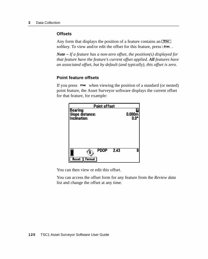
3 Data Collection
Offsets
Any form that displays the position of a feature contains anOsoftkey. To view and/or edit the offset for this feature, pressO .
Note – If a feature has a non-zero offset, the position(s) displayed forthat feature have the feature’s current offset applied. All features havean associated offset, but by default (and typically), this offset is zero.
Point feature offsets
If you pressO when viewing the position of a standard (or nested)point feature, the Asset Surveyor software displays the current offsetfor that feature, for example:
You can then view or edit this offset.
You can access the offset form for any feature from the Review datalist and change the offset at any time.
120 TSC1 Asset Surveyor Software User Guide
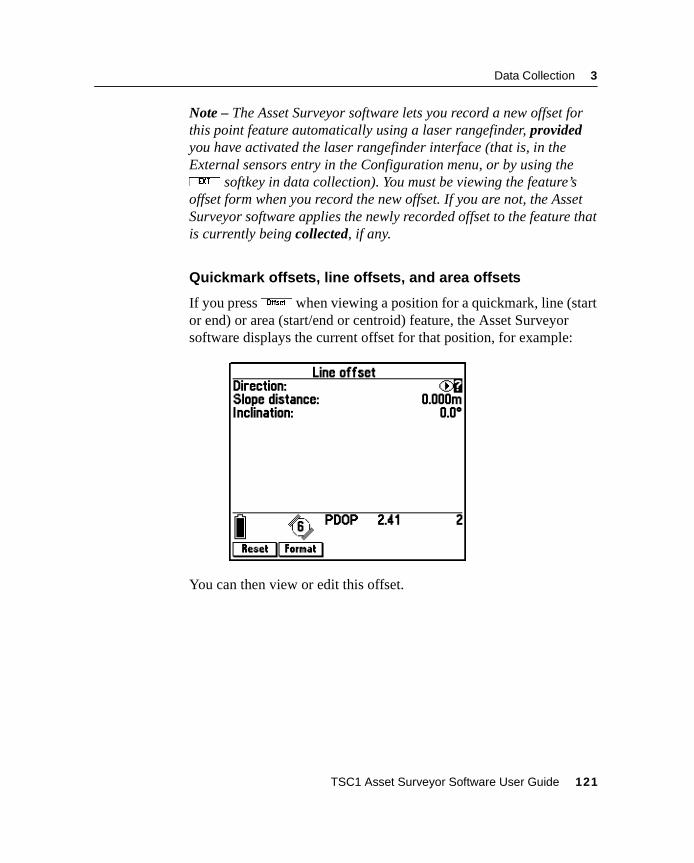
Data Collection 3
Note – The Asset Surveyor software lets you record a new offset forthis point feature automatically using a laser rangefinder, providedyou have activated the laser rangefinder interface (that is, in theExternal sensors entry in the Configuration menu, or by using theX softkey in data collection). You must be viewing the feature’soffset form when you record the new offset. If you are not, the AssetSurveyor software applies the newly recorded offset to the feature thatis currently being collected, if any.
Quickmark offsets, line offsets, and area offsets
If you pressO when viewing a position for a quickmark, line (startor end) or area (start/end or centroid) feature, the Asset Surveyorsoftware displays the current offset for that position, for example:
You can then view or edit this offset.
TSC1 Asset Surveyor Software User Guide 121
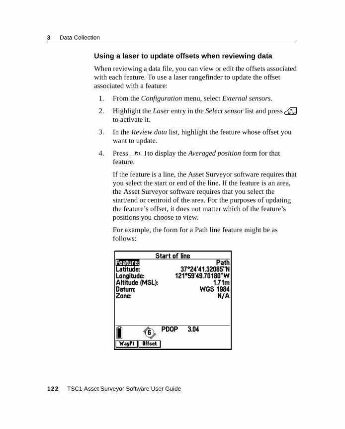
3 Data Collection
Using a laser to update offsets when reviewing data
When reviewing a data file, you can view or edit the offsets associatedwith each feature. To use a laser rangefinder to update the offsetassociated with a feature:
1. From the Configuration menu, select External sensors.
2. Highlight the Laser entry in the Select sensor list and press\to activate it.
3. In the Review data list, highlight the feature whose offset youwant to update.
4. PressQ to display the Averaged position form for thatfeature.
If the feature is a line, the Asset Surveyor software requires thatyou select the start or end of the line. If the feature is an area,the Asset Surveyor software requires that you select thestart/end or centroid of the area. For the purposes of updatingthe feature’s offset, it does not matter which of the feature’spositions you choose to view.
For example, the form for a Path line feature might be asfollows:
122 TSC1 Asset Surveyor Software User Guide
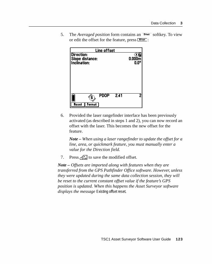
Data Collection 3
5. The Averaged position form contains anO softkey. To viewor edit the offset for the feature, pressO:
6. Provided the laser rangefinder interface has been previouslyactivated (as described in steps 1 and 2), you can now record anoffset with the laser. This becomes the new offset for thefeature.
Note – When using a laser rangefinder to update the offset for aline, area, or quickmark feature, you must manually enter avalue for the Direction field.
7. Press\ to save the modified offset.
Note – Offsets are imported along with features when they aretransferred from the GPS Pathfinder Office software. However, unlessthey were updated during the same data collection session, they willbe reset to the current constant offset value if the feature’s GPSposition is updated. When this happens the Asset Surveyor softwaredisplays the message Existing offset reset.
TSC1 Asset Surveyor Software User Guide 123
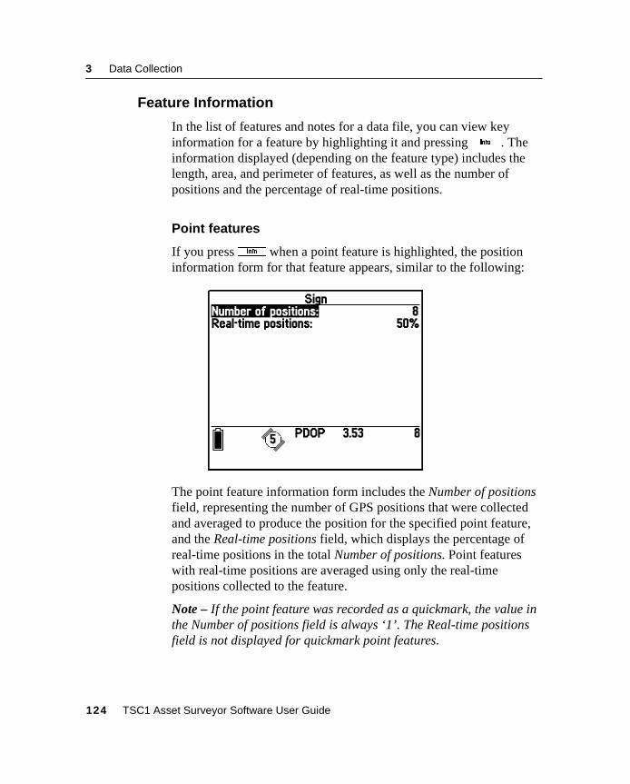
3 Data Collection
3.3.12 Feature Information
In the list of features and notes for a data file, you can view keyinformation for a feature by highlighting it and pressingI . Theinformation displayed (depending on the feature type) includes thelength, area, and perimeter of features, as well as the number ofpositions and the percentage of real-time positions.
Point features
If you pressI when a point feature is highlighted, the positioninformation form for that feature appears, similar to the following:
The point feature information form includes the Number of positionsfield, representing the number of GPS positions that were collectedand averaged to produce the position for the specified point feature,and the Real-time positions field, which displays the percentage ofreal-time positions in the total Number of positions. Point featureswith real-time positions are averaged using only the real-timepositions collected to the feature.
Note – If the point feature was recorded as a quickmark, the value inthe Number of positions field is always ‘1’. The Real-time positionsfield is not displayed for quickmark point features.
124 TSC1 Asset Surveyor Software User Guide
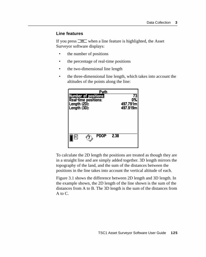
Data Collection 3
Line features
If you pressI when a line feature is highlighted, the AssetSurveyor software displays:
• the number of positions
• the percentage of real-time positions
• the two-dimensional line length
• the three-dimensional line length, which takes into account thealtitudes of the points along the line:
To calculate the 2D length the positions are treated as though they arein a straight line and are simply added together. 3D length mirrors thetopography of the land, and the sum of the distances between thepositions in the line takes into account the vertical altitude of each.
Figure 3.1 shows the difference between 2D length and 3D length. Inthe example shown, the 2D length of the line shown is the sum of thedistances from A to B. The 3D length is the sum of the distances fromA to C.
TSC1 Asset Surveyor Software User Guide 125
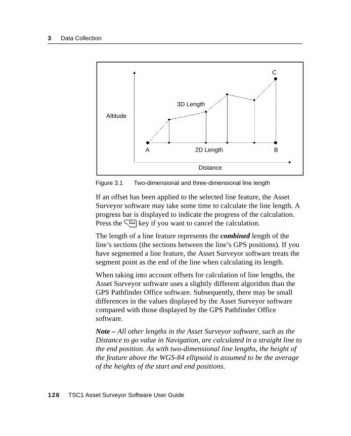
3 Data Collection
Figure 3.1 Two-dimensional and three-dimensional line length
If an offset has been applied to the selected line feature, the AssetSurveyor software may take some time to calculate the line length. Aprogress bar is displayed to indicate the progress of the calculation.Press the= key if you want to cancel the calculation.
The length of a line feature represents the combined length of theline’s sections (the sections between the line’s GPS positions). If youhave segmented a line feature, the Asset Surveyor software treats thesegment point as the end of the line when calculating its length.
When taking into account offsets for calculation of line lengths, theAsset Surveyor software uses a slightly different algorithm than theGPS Pathfinder Office software. Subsequently, there may be smalldifferences in the values displayed by the Asset Surveyor softwarecompared with those displayed by the GPS Pathfinder Officesoftware.
Note – All other lengths in the Asset Surveyor software, such as theDistance to go value in Navigation, are calculated in a straight line tothe end position. As with two-dimensional line lengths, the height ofthe feature above the WGS-84 ellipsoid is assumed to be the averageof the heights of the start and end positions.
A B
C
2D Length
3D Length
Altitude
Distance
126 TSC1 Asset Surveyor Software User Guide
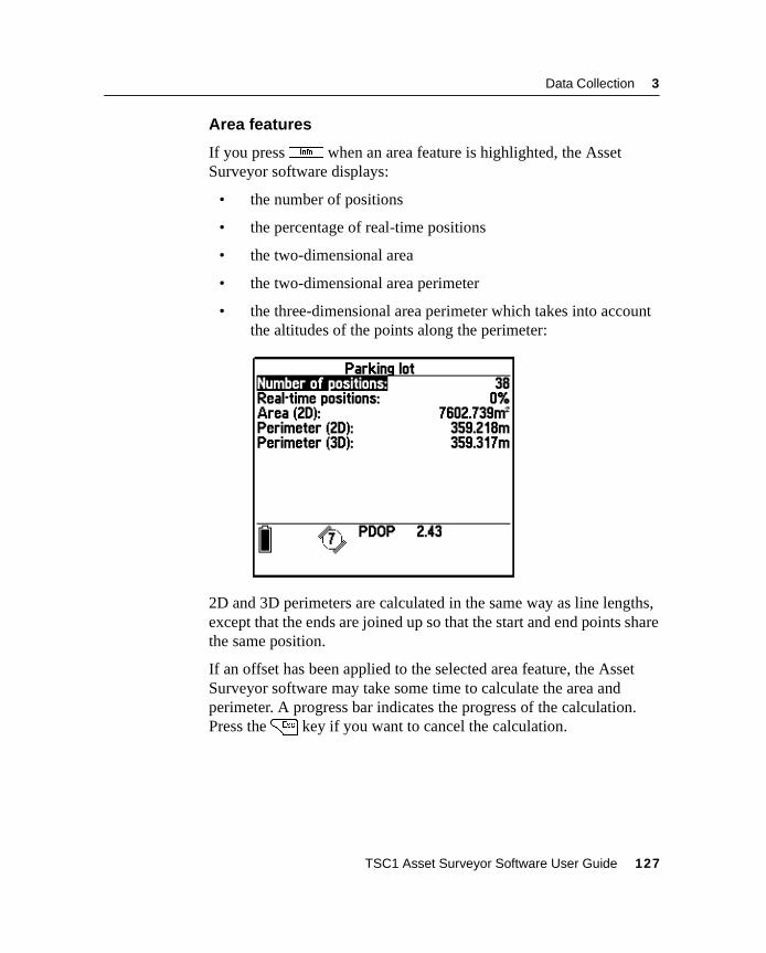
Data Collection 3
Area features
If you pressI when an area feature is highlighted, the AssetSurveyor software displays:
• the number of positions
• the percentage of real-time positions
• the two-dimensional area
• the two-dimensional area perimeter
• the three-dimensional area perimeter which takes into accountthe altitudes of the points along the perimeter:
2D and 3D perimeters are calculated in the same way as line lengths,except that the ends are joined up so that the start and end points sharethe same position.
If an offset has been applied to the selected area feature, the AssetSurveyor software may take some time to calculate the area andperimeter. A progress bar indicates the progress of the calculation.Press the= key if you want to cancel the calculation.
TSC1 Asset Surveyor Software User Guide 127
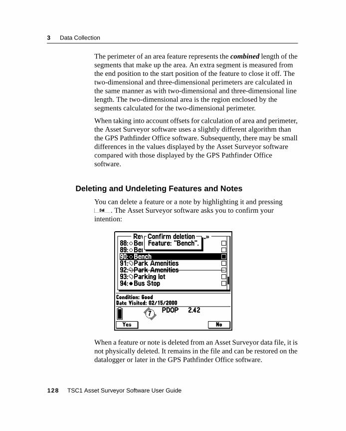
3 Data Collection
The perimeter of an area feature represents the combined length of thesegments that make up the area. An extra segment is measured fromthe end position to the start position of the feature to close it off. Thetwo-dimensional and three-dimensional perimeters are calculated inthe same manner as with two-dimensional and three-dimensional linelength. The two-dimensional area is the region enclosed by thesegments calculated for the two-dimensional perimeter.
When taking into account offsets for calculation of area and perimeter,the Asset Surveyor software uses a slightly different algorithm thanthe GPS Pathfinder Office software. Subsequently, there may be smalldifferences in the values displayed by the Asset Surveyor softwarecompared with those displayed by the GPS Pathfinder Officesoftware.
3.3.13 Deleting and Undeleting Features and Notes
You can delete a feature or a note by highlighting it and pressingd . The Asset Surveyor software asks you to confirm yourintention:
When a feature or note is deleted from an Asset Surveyor data file, it isnot physically deleted. It remains in the file and can be restored on thedatalogger or later in the GPS Pathfinder Office software.
128 TSC1 Asset Surveyor Software User Guide
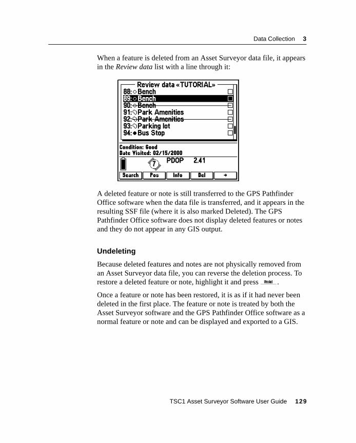
Data Collection 3
When a feature is deleted from an Asset Surveyor data file, it appearsin the Review data list with a line through it:
A deleted feature or note is still transferred to the GPS PathfinderOffice software when the data file is transferred, and it appears in theresulting SSF file (where it is also marked Deleted). The GPSPathfinder Office software does not display deleted features or notesand they do not appear in any GIS output.
Undeleting
Because deleted features and notes are not physically removed froman Asset Surveyor data file, you can reverse the deletion process. Torestore a deleted feature or note, highlight it and pressu .
Once a feature or note has been restored, it is as if it had never beendeleted in the first place. The feature or note is treated by both theAsset Surveyor software and the GPS Pathfinder Office software as anormal feature or note and can be displayed and exported to a GIS.
TSC1 Asset Surveyor Software User Guide 129
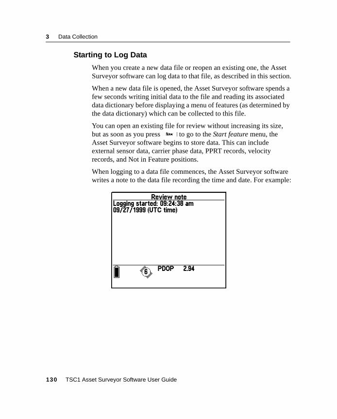
3 Data Collection
3.3.14 Starting to Log Data
When you create a new data file or reopen an existing one, the AssetSurveyor software can log data to that file, as described in this section.
When a new data file is opened, the Asset Surveyor software spends afew seconds writing initial data to the file and reading its associateddata dictionary before displaying a menu of features (as determined bythe data dictionary) which can be collected to this file.
You can open an existing file for review without increasing its size,but as soon as you pressb to go to the Start feature menu, theAsset Surveyor software begins to store data. This can includeexternal sensor data, carrier phase data, PPRT records, velocityrecords, and Not in Feature positions.
When logging to a data file commences, the Asset Surveyor softwarewrites a note to the data file recording the time and date. For example:
130 TSC1 Asset Surveyor Software User Guide
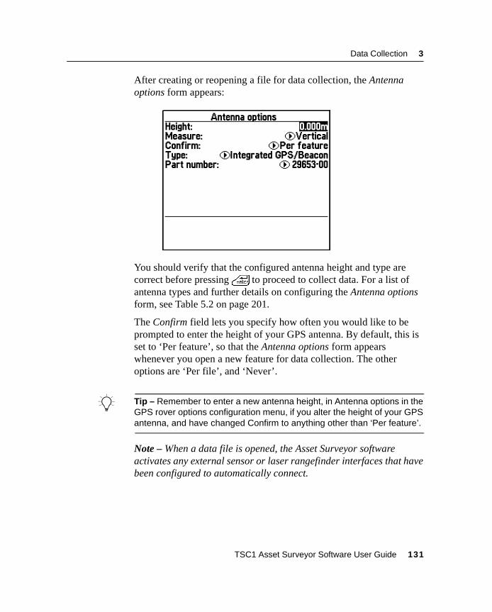
Data Collection 3
After creating or reopening a file for data collection, the Antennaoptions form appears:
You should verify that the configured antenna height and type arecorrect before pressing\ to proceed to collect data. For a list ofantenna types and further details on configuring the Antenna optionsform, see Table 5.2 on page 201.
The Confirm field lets you specify how often you would like to beprompted to enter the height of your GPS antenna. By default, this isset to ‘Per feature’, so that the Antenna options form appearswhenever you open a new feature for data collection. The otheroptions are ‘Per file’, and ‘Never’.
B Tip – Remember to enter a new antenna height, in Antenna options in theGPS rover options configuration menu, if you alter the height of your GPSantenna, and have changed Confirm to anything other than ‘Per feature’.
Note – When a data file is opened, the Asset Surveyor softwareactivates any external sensor or laser rangefinder interfaces that havebeen configured to automatically connect.
TSC1 Asset Surveyor Software User Guide 131
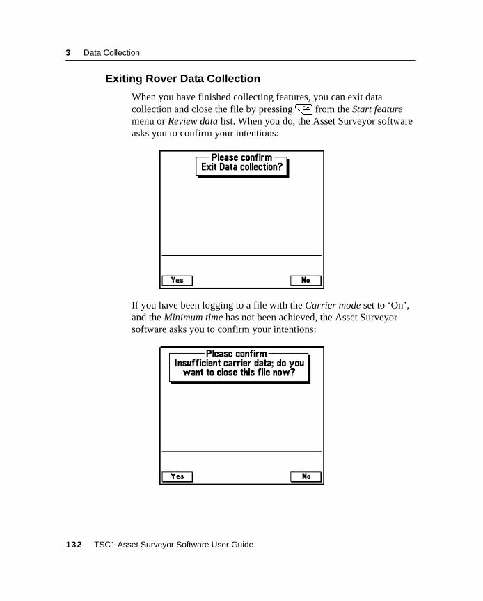
3 Data Collection
3.3.15 Exiting Rover Data Collection
When you have finished collecting features, you can exit datacollection and close the file by pressing= from the Start featuremenu or Review data list. When you do, the Asset Surveyor softwareasks you to confirm your intentions:
If you have been logging to a file with the Carrier mode set to ‘On’,and the Minimum time has not been achieved, the Asset Surveyorsoftware asks you to confirm your intentions:
132 TSC1 Asset Surveyor Software User Guide
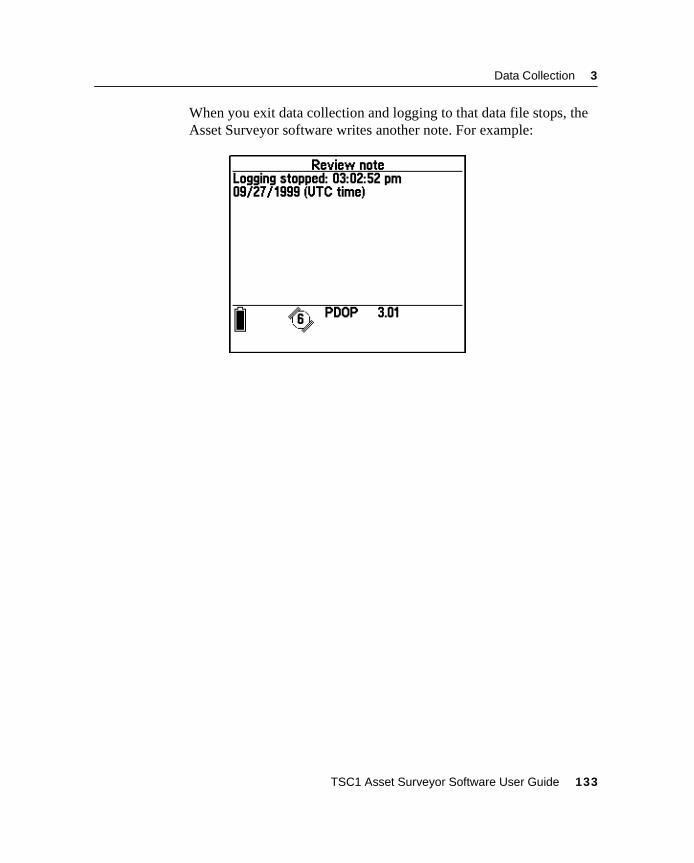
Data Collection 3
When you exit data collection and logging to that data file stops, theAsset Surveyor software writes another note. For example:
TSC1 Asset Surveyor Software User Guide 133
3 Data Collection
3.4 Create Base FileBase data is used to differentially correct rover data. A base stationrecords GPS data from a receiver at a known, fixed location. Providedthe rover is relatively close to the base station (within about 250 km),certain errors in GPS positions, such as Selective Availability, clockerrors, transmission delays, and orbital errors, are common to both thebase station and rover. Thus the difference between the base station’sactual position and its reported position at any time can be used tocorrect the reported position of the rover at the same time, bycanceling out the common error components.
Although it also uses the .ssf extension, a base data file recordsdifferent information from a rover data file. It includes data on satellitepositions and health, and all its position data is for approximately thesame location. It does not record feature or attribute information, andcannot be used as a rover file.
The first step in setting up a GPS base station is to configure the GPSBase station options. For information on configuration options, seeGPS Base Station Options, page 205.
You can reconfigure the base station options once the base station hasstarted operating, but it is good practice to configure the AssetSurveyor software first, so that when a base station is started it canimmediately log the data you require.
When you select the Create base file entry from the Data collectionmenu, the Asset Surveyor software first checks that it is connected to,and able to communicate with, a GPS receiver. If it is not connected toa GPS receiver at all, the Asset Surveyor software does not continuewith the base station session.
Note – If the connected receiver is a Series 4000, GPS Total Station4800, or Site Surveyor 4400 receiver the Real-time output mode in theReal-time output options form must be set to ‘On’ if you want to start abase station session.
134 TSC1 Asset Surveyor Software User Guide
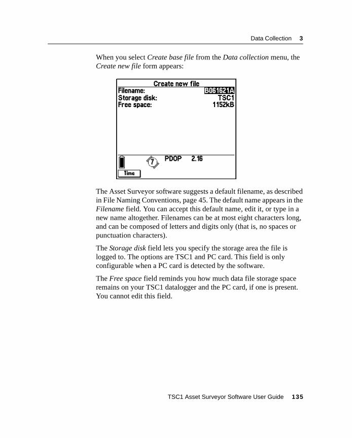
Data Collection 3
When you select Create base file from the Data collection menu, theCreate new file form appears:
The Asset Surveyor software suggests a default filename, as describedin File Naming Conventions, page 45. The default name appears in theFilename field. You can accept this default name, edit it, or type in anew name altogether. Filenames can be at most eight characters long,and can be composed of letters and digits only (that is, no spaces orpunctuation characters).
The Storage disk field lets you specify the storage area the file islogged to. The options are TSC1 and PC card. This field is onlyconfigurable when a PC card is detected by the software.
The Free space field reminds you how much data file storage spaceremains on your TSC1 datalogger and the PC card, if one is present.You cannot edit this field.
TSC1 Asset Surveyor Software User Guide 135
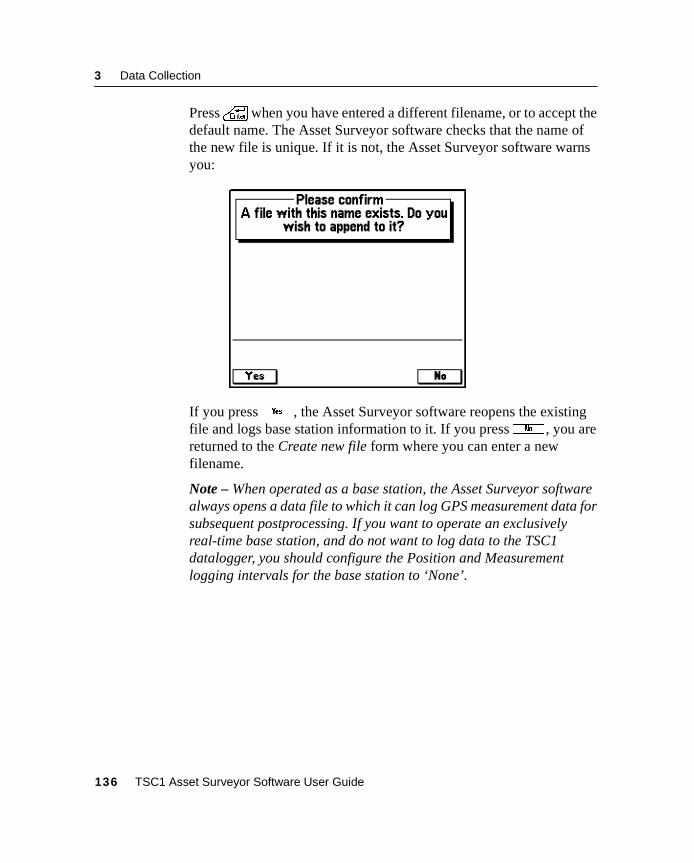
3 Data Collection
Press\ when you have entered a different filename, or to accept thedefault name. The Asset Surveyor software checks that the name ofthe new file is unique. If it is not, the Asset Surveyor software warnsyou:
If you pressy, the Asset Surveyor software reopens the existingfile and logs base station information to it. If you pressn , you arereturned to the Create new file form where you can enter a newfilename.
Note – When operated as a base station, the Asset Surveyor softwarealways opens a data file to which it can log GPS measurement data forsubsequent postprocessing. If you want to operate an exclusivelyreal-time base station, and do not want to log data to the TSC1datalogger, you should configure the Position and Measurementlogging intervals for the base station to ‘None’.
136 TSC1 Asset Surveyor Software User Guide
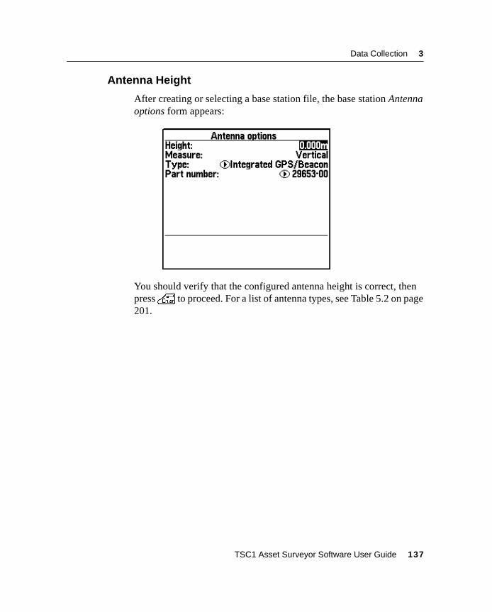
Data Collection 3
3.4.1 Antenna Height
After creating or selecting a base station file, the base station Antennaoptions form appears:
You should verify that the configured antenna height is correct, thenpress\ to proceed. For a list of antenna types, see Table 5.2 on page201.
TSC1 Asset Surveyor Software User Guide 137
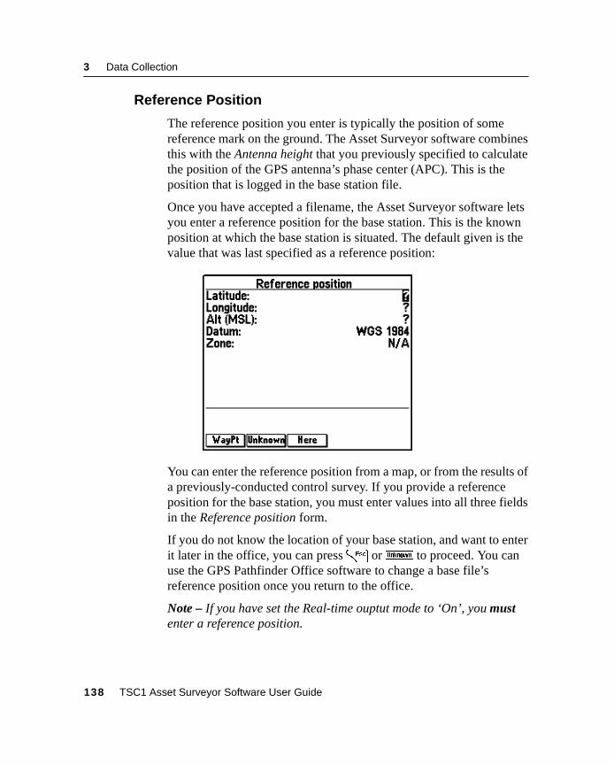
3 Data Collection
3.4.2 Reference Position
The reference position you enter is typically the position of somereference mark on the ground. The Asset Surveyor software combinesthis with the Antenna height that you previously specified to calculatethe position of the GPS antenna’s phase center (APC). This is theposition that is logged in the base station file.
Once you have accepted a filename, the Asset Surveyor software letsyou enter a reference position for the base station. This is the knownposition at which the base station is situated. The default given is thevalue that was last specified as a reference position:
You can enter the reference position from a map, or from the results ofa previously-conducted control survey. If you provide a referenceposition for the base station, you must enter values into all three fieldsin the Reference position form.
If you do not know the location of your base station, and want to enterit later in the office, you can press= orU to proceed. You canuse the GPS Pathfinder Office software to change a base file’sreference position once you return to the office.
Note – If you have set the Real-time ouptut mode to ‘On’, you mustenter a reference position.
138 TSC1 Asset Surveyor Software User Guide
Data Collection 3
If you have previously recorded the location of the base station as awaypoint, pressw to access the menu of waypoints. Selecting awaypoint from this menu automatically fills in the Reference positionfields with the location of that waypoint.
B Tip – If you regularly operate a base station on more than one location,you can set up waypoints for each base location. This makes selection ofthe reference position very easy.
You can pressh to fill in the reference position with the currentGPS position (if any).
Note – Unless you are receiving differential corrections, the accuracyof the current GPS position is subject to Selective Availability (S/A).
C Warning – If you choose to append to an existing data file, you cannotspecify a new reference position. If you have moved to a different location,you must create a new base file. Consequently, if you reopen a base file,make sure that you are at the same exact location that the base file wasinitially created. The reference position of the base station is stored whenthe base file is first created, and positions subsequently appended to thefile will be inaccurate if the receiver is not at the same reference position.
TSC1 Asset Surveyor Software User Guide 139
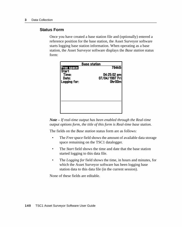
3 Data Collection
3.4.3 Status Form
Once you have created a base station file and (optionally) entered areference position for the base station, the Asset Surveyor softwarestarts logging base station information. When operating as a basestation, the Asset Surveyor software displays the Base station statusform:
Note – If real-time output has been enabled through the Real-timeoutput options form, the title of this form is Real-time base station.
The fields on the Base station status form are as follows:
• The Free space field shows the amount of available data storagespace remaining on the TSC1 datalogger.
• The Start field shows the time and date that the base stationstarted logging to this data file.
• The Logging for field shows the time, in hours and minutes, forwhich the Asset Surveyor software has been logging basestation data to this data file (in the current session).
None of these fields are editable.
140 TSC1 Asset Surveyor Software User Guide
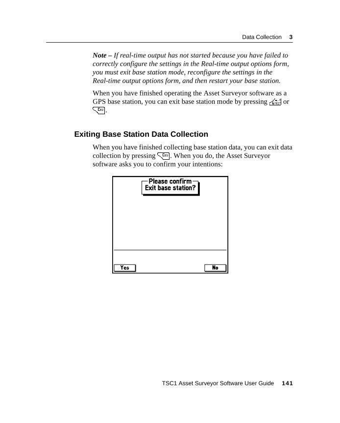
Data Collection 3
Note – If real-time output has not started because you have failed tocorrectly configure the settings in the Real-time output options form,you must exit base station mode, reconfigure the settings in theReal-time output options form, and then restart your base station.
When you have finished operating the Asset Surveyor software as aGPS base station, you can exit base station mode by pressing\ or= .
3.4.4 Exiting Base Station Data Collection
When you have finished collecting base station data, you can exit datacollection by pressing= . When you do, the Asset Surveyorsoftware asks you to confirm your intentions:
TSC1 Asset Surveyor Software User Guide 141

3 Data Collection
142 TSC1 Asset Surveyor Software User Guide

C H A P T E R
4
4 File ManagerIn this chapter:
■ Introduction
■ Deleting data files
■ Rename file
■ Copy file(s)
■ Move file(s)
■ File transfer
■ Data dictionaries
■ Coordinate system files
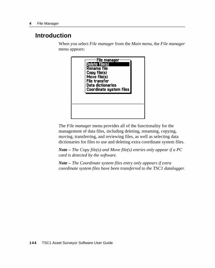
4 File Manager
4.1 IntroductionWhen you select File manager from the Main menu, the File managermenu appears:
The File manager menu provides all of the functionality for themanagement of data files, including deleting, renaming, copying,moving, transferring, and reviewing files, as well as selecting datadictionaries for files to use and deleting extra coordinate system files.
Note – The Copy file(s) and Move file(s) entries only appear if a PCcard is detected by the software.
Note – The Coordinate system files entry only appears if extracoordinate system files have been transferred to the TSC1 datalogger.
144 TSC1 Asset Surveyor Software User Guide
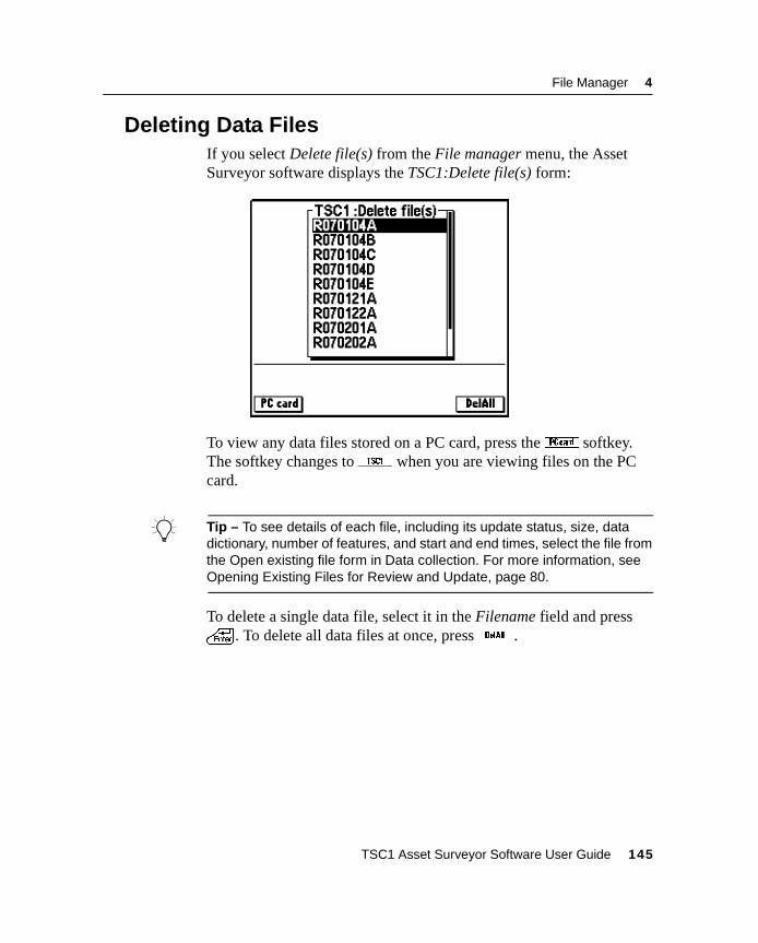
File Manager 4
4.2 Deleting Data FilesIf you select Delete file(s) from the File manager menu, the AssetSurveyor software displays the TSC1:Delete file(s) form:
To view any data files stored on a PC card, press theC softkey.The softkey changes toc when you are viewing files on the PCcard.
B Tip – To see details of each file, including its update status, size, datadictionary, number of features, and start and end times, select the file fromthe Open existing file form in Data collection. For more information, seeOpening Existing Files for Review and Update, page 80.
To delete a single data file, select it in the Filename field and press\ . To delete all data files at once, pressD .
TSC1 Asset Surveyor Software User Guide 145
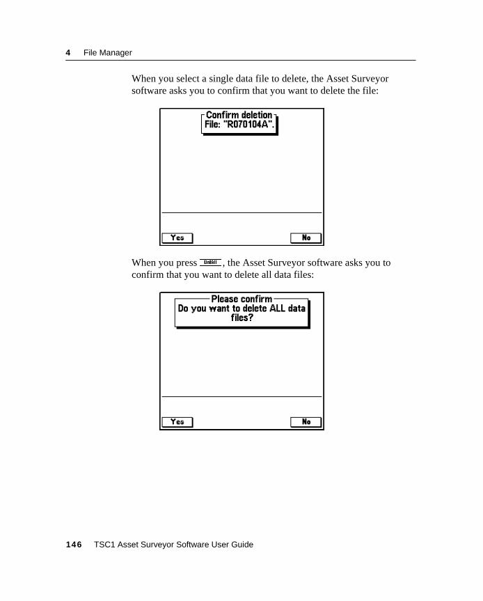
4 File Manager
When you select a single data file to delete, the Asset Surveyorsoftware asks you to confirm that you want to delete the file:
When you pressD , the Asset Surveyor software asks you toconfirm that you want to delete all data files:
146 TSC1 Asset Surveyor Software User Guide
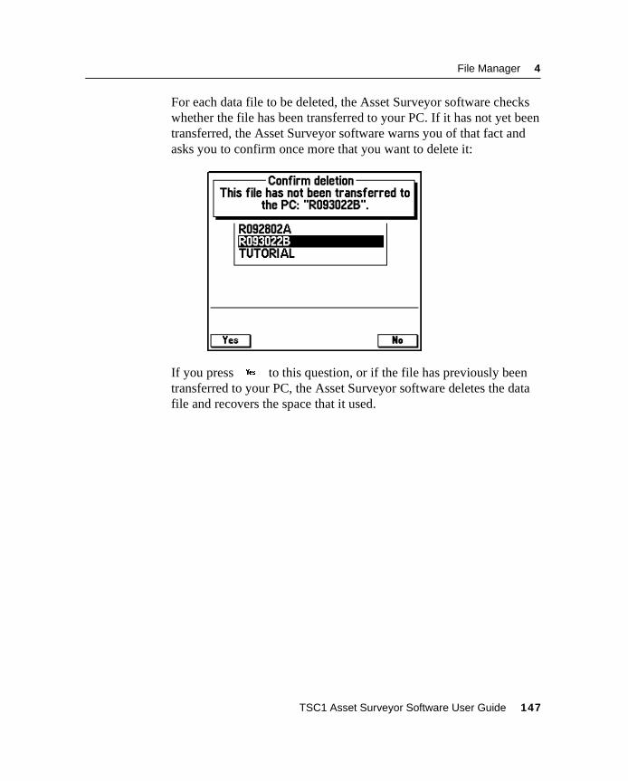
File Manager 4
For each data file to be deleted, the Asset Surveyor software checkswhether the file has been transferred to your PC. If it has not yet beentransferred, the Asset Surveyor software warns you of that fact andasks you to confirm once more that you want to delete it:
If you pressy to this question, or if the file has previously beentransferred to your PC, the Asset Surveyor software deletes the datafile and recovers the space that it used.
TSC1 Asset Surveyor Software User Guide 147
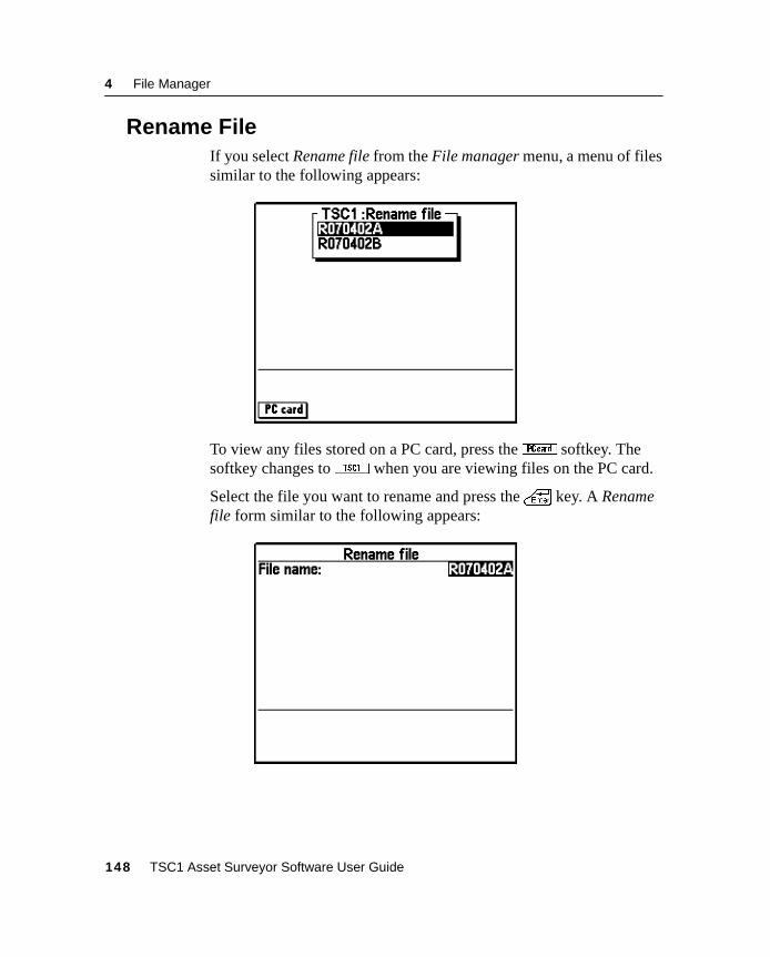
4 File Manager
4.3 Rename FileIf you select Rename file from the File manager menu, a menu of filessimilar to the following appears:
To view any files stored on a PC card, press theC softkey. Thesoftkey changes toc when you are viewing files on the PC card.
Select the file you want to rename and press the\ key. A Renamefile form similar to the following appears:
148 TSC1 Asset Surveyor Software User Guide
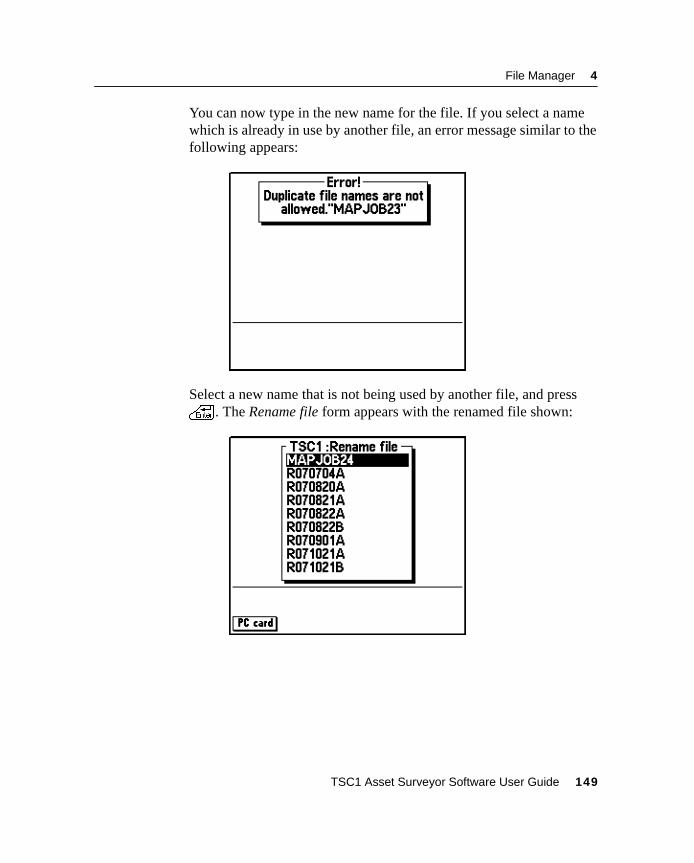
File Manager 4
You can now type in the new name for the file. If you select a namewhich is already in use by another file, an error message similar to thefollowing appears:
Select a new name that is not being used by another file, and press\ . The Rename file form appears with the renamed file shown:
TSC1 Asset Surveyor Software User Guide 149
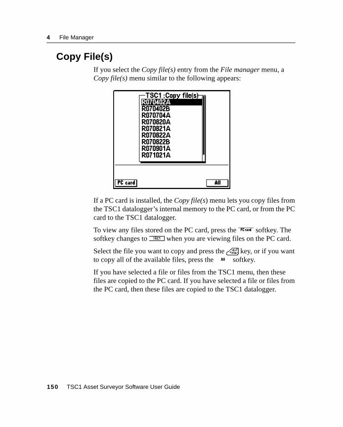
4 File Manager
4.4 Copy File(s)If you select the Copy file(s) entry from the File manager menu, aCopy file(s) menu similar to the following appears:
If a PC card is installed, the Copy file(s) menu lets you copy files fromthe TSC1 datalogger’s internal memory to the PC card, or from the PCcard to the TSC1 datalogger.
To view any files stored on the PC card, press theC softkey. Thesoftkey changes toc when you are viewing files on the PC card.
Select the file you want to copy and press the\ key, or if you wantto copy all of the available files, press the0 softkey.
If you have selected a file or files from the TSC1 menu, then thesefiles are copied to the PC card. If you have selected a file or files fromthe PC card, then these files are copied to the TSC1 datalogger.
150 TSC1 Asset Surveyor Software User Guide
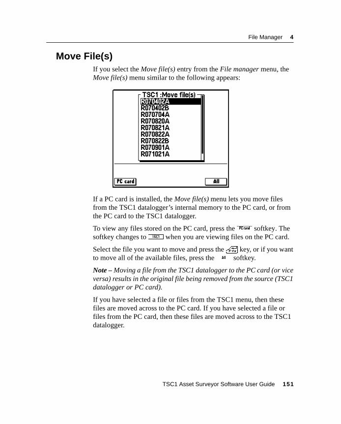
File Manager 4
4.5 Move File(s)If you select the Move file(s) entry from the File manager menu, theMove file(s) menu similar to the following appears:
If a PC card is installed, the Move file(s) menu lets you move filesfrom the TSC1 datalogger’s internal memory to the PC card, or fromthe PC card to the TSC1 datalogger.
To view any files stored on the PC card, press theC softkey. Thesoftkey changes toc when you are viewing files on the PC card.
Select the file you want to move and press the\ key, or if you wantto move all of the available files, press the0 softkey.
Note – Moving a file from the TSC1 datalogger to the PC card (or viceversa) results in the original file being removed from the source (TSC1datalogger or PC card).
If you have selected a file or files from the TSC1 menu, then thesefiles are moved across to the PC card. If you have selected a file orfiles from the PC card, then these files are moved across to the TSC1datalogger.
TSC1 Asset Surveyor Software User Guide 151
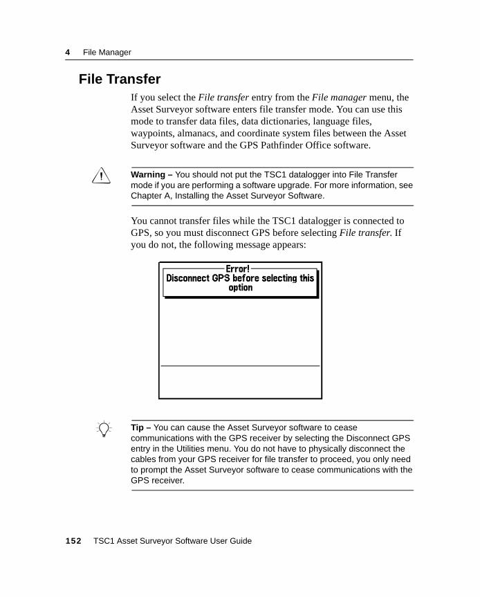
4 File Manager
4.6 File TransferIf you select the File transfer entry from the File manager menu, theAsset Surveyor software enters file transfer mode. You can use thismode to transfer data files, data dictionaries, language files,waypoints, almanacs, and coordinate system files between the AssetSurveyor software and the GPS Pathfinder Office software.
C Warning – You should not put the TSC1 datalogger into File Transfermode if you are performing a software upgrade. For more information, seeChapter A, Installing the Asset Surveyor Software.
You cannot transfer files while the TSC1 datalogger is connected toGPS, so you must disconnect GPS before selecting File transfer. Ifyou do not, the following message appears:
B Tip – You can cause the Asset Surveyor software to ceasecommunications with the GPS receiver by selecting the Disconnect GPSentry in the Utilities menu. You do not have to physically disconnect thecables from your GPS receiver for file transfer to proceed, you only needto prompt the Asset Surveyor software to cease communications with theGPS receiver.
152 TSC1 Asset Surveyor Software User Guide
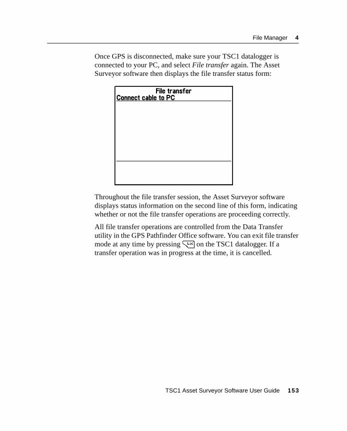
File Manager 4
Once GPS is disconnected, make sure your TSC1 datalogger isconnected to your PC, and select File transfer again. The AssetSurveyor software then displays the file transfer status form:
Throughout the file transfer session, the Asset Surveyor softwaredisplays status information on the second line of this form, indicatingwhether or not the file transfer operations are proceeding correctly.
All file transfer operations are controlled from the Data Transferutility in the GPS Pathfinder Office software. You can exit file transfermode at any time by pressing= on the TSC1 datalogger. If atransfer operation was in progress at the time, it is cancelled.
TSC1 Asset Surveyor Software User Guide 153
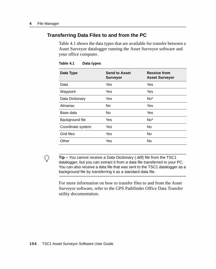
4 File Manager
4.6.1 Transferring Data Files to and from the PC
Table 4.1 shows the data types that are available for transfer between aAsset Surveyor datalogger running the Asset Surveyor software andyour office computer.
B Tip – You cannot receive a Data Dictionary (.ddf) file from the TSC1datalogger, but you can extract it from a data file transferred to your PC.You can also receive a data file that was sent to the TSC1 datalogger as abackground file by transferring it as a standard data file.
For more information on how to transfer files to and from the AssetSurveyor software, refer to the GPS Pathfinder Office Data Transferutility documentation.
Table 4.1 Data types
Data Type Send to AssetSurveyor
Receive fromAsset Surveyor
Data Yes Yes
Waypoint Yes Yes
Data Dictionary Yes No*
Almanac No Yes
Base data No Yes
Background file Yes No*
Coordinate system Yes No
Grid files Yes No
Other Yes No
154 TSC1 Asset Surveyor Software User Guide
File Manager 4
4.6.2 Other File Types
Other file types that can be transferred to the Asset Surveyor softwareare as follows:
• satDGPS.ini
A file containing the most recent details of DGPS satellites andtheir frequencies.
• *.cse
A file containing coordinate system definitions. This can beedited on your PC using the Coordinate System Manager in theGPS Pathfinder Office software, and then loaded onto a fleet ofTSC1 dataloggers to ensure that they all have the samecoordinate systems (and only those coordinate systems that arerequired for your application). Four other file types areassociated with the transfer of custom coordinate systems:
– *.dgf (datum grid file)
– *.mrf (multiple regression file)
– *.pgf (projection grid file)
– *.ggf (geoid grid file)
For more information about these file types, refer to the GPSPathfinder Office documentation.
TSC1 Asset Surveyor Software User Guide 155
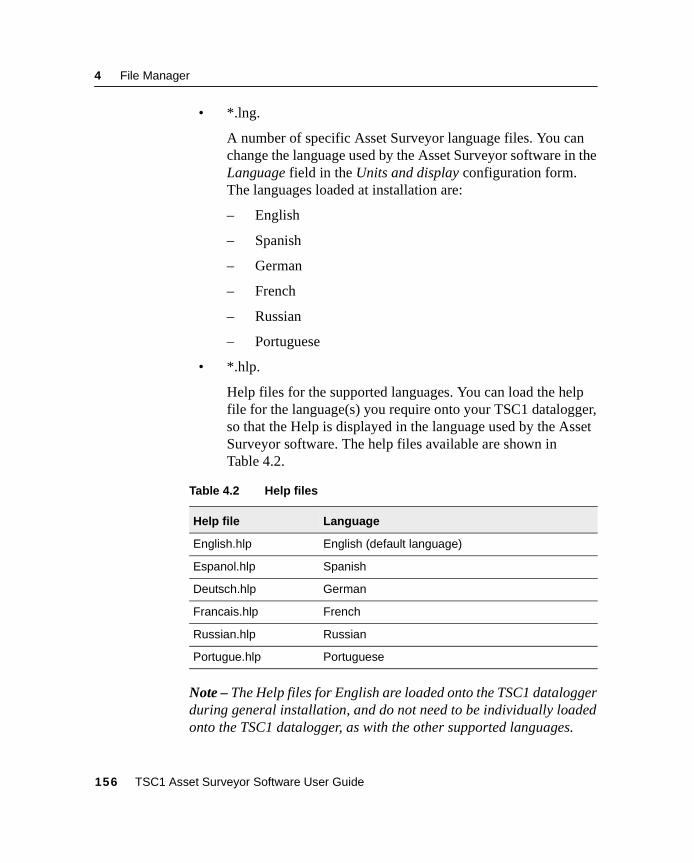
4 File Manager
• *.lng.
A number of specific Asset Surveyor language files. You canchange the language used by the Asset Surveyor software in theLanguage field in the Units and display configuration form.The languages loaded at installation are:
– English
– Spanish
– German
– French
– Russian
– Portuguese
• *.hlp.
Help files for the supported languages. You can load the helpfile for the language(s) you require onto your TSC1 datalogger,so that the Help is displayed in the language used by the AssetSurveyor software. The help files available are shown inTable 4.2.
Note – The Help files for English are loaded onto the TSC1 dataloggerduring general installation, and do not need to be individually loadedonto the TSC1 datalogger, as with the other supported languages.
Table 4.2 Help files
Help file Language
English.hlp English (default language)
Espanol.hlp Spanish
Deutsch.hlp German
Francais.hlp French
Russian.hlp Russian
Portugue.hlp Portuguese
156 TSC1 Asset Surveyor Software User Guide
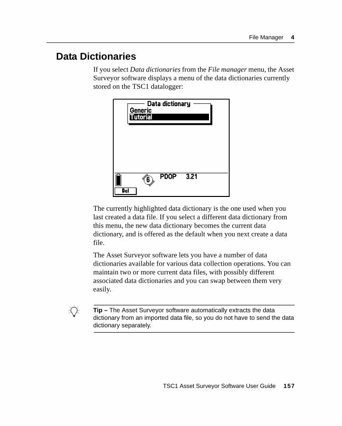
File Manager 4
4.7 Data DictionariesIf you select Data dictionaries from the File manager menu, the AssetSurveyor software displays a menu of the data dictionaries currentlystored on the TSC1 datalogger:
The currently highlighted data dictionary is the one used when youlast created a data file. If you select a different data dictionary fromthis menu, the new data dictionary becomes the current datadictionary, and is offered as the default when you next create a datafile.
The Asset Surveyor software lets you have a number of datadictionaries available for various data collection operations. You canmaintain two or more current data files, with possibly differentassociated data dictionaries and you can swap between them veryeasily.
B Tip – The Asset Surveyor software automatically extracts the datadictionary from an imported data file, so you do not have to send the datadictionary separately.
TSC1 Asset Surveyor Software User Guide 157
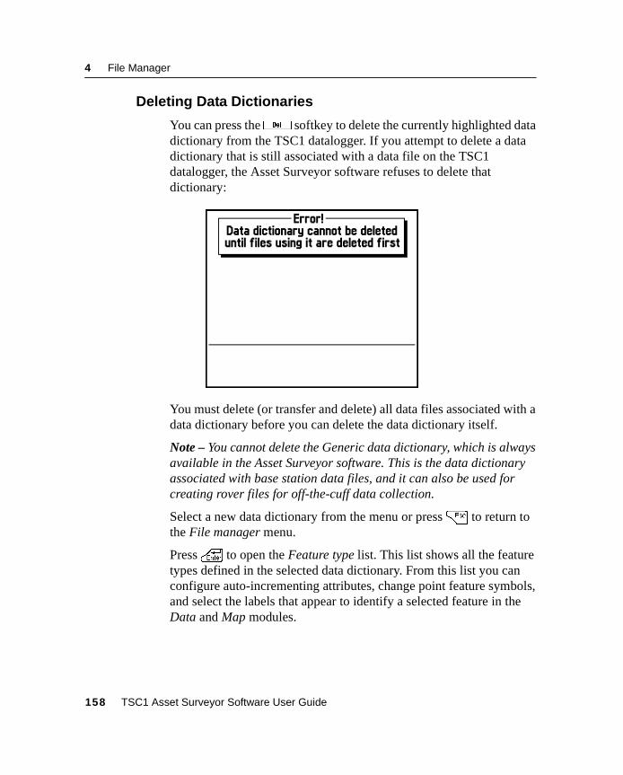
4 File Manager
4.7.1 Deleting Data Dictionaries
You can press thed softkey to delete the currently highlighted datadictionary from the TSC1 datalogger. If you attempt to delete a datadictionary that is still associated with a data file on the TSC1datalogger, the Asset Surveyor software refuses to delete thatdictionary:
You must delete (or transfer and delete) all data files associated with adata dictionary before you can delete the data dictionary itself.
Note – You cannot delete the Generic data dictionary, which is alwaysavailable in the Asset Surveyor software. This is the data dictionaryassociated with base station data files, and it can also be used forcreating rover files for off-the-cuff data collection.
Select a new data dictionary from the menu or press= to return tothe File manager menu.
Press\ to open the Feature type list. This list shows all the featuretypes defined in the selected data dictionary. From this list you canconfigure auto-incrementing attributes, change point feature symbols,and select the labels that appear to identify a selected feature in theData and Map modules.
158 TSC1 Asset Surveyor Software User Guide
File Manager 4
4.7.2 Auto-Incrementing Attributes
From the Feature type list, select a feature and press~ to displaythe <feature> Auto increment settings form. From this form you canconfigure the auto-incrementing attributes for that feature in theselected data dictionary. If the selected feature has no text or numericattributes, the~ softkey is not available.
The Auto increment settings form contains a field for each text ornumeric attribute in the selected feature. To set the auto-incrementoptions for an attribute, highlight its field and enter an increment ordecrement value. To indicate an increment, enter a positive number.To indicate a decrement, use the- softkey to enter a negativenumber. To turn automatic incrementing off for this attribute, enter 0or press7 .
Rules for auto-incrementing
The auto-incrementing function lets you configure an increasing ordecreasing sequence of values for numeric attributes or numericvalues in text attributes. Auto-increment settings can also beconfigured in the Data Dictionary Editor utility in the GPS PathfinderOffice software.
Each time you create a new feature, any auto-incrementing attribute isautomatically filled in with a default value. This value is calculated byadding the increment or decrement specified for this attribute to thevalue stored in the last feature of this type that you added or edited. Ina text attribute, only numeric characters are incremented. Alphabeticcharacters are never incremented. For example, if the last value was27A, the next number in a sequence with an increment of 1 is 28A.
Note – If a text attribute consists of numeric characters interspersedwith alphabetic characters, for example Z496-JD98, only therightmost number is incremented. In this example, the next number ina sequence with an increment of 1 is Z496-JD99. Only the number 98is incremented; 496 is always left unchanged.
TSC1 Asset Surveyor Software User Guide 159
4 File Manager
If the last attribute value was null or contained no numeric characters,the attribute is not automatically incremented and the last attribute’svalue is used again. The first attribute you add also defaults to null, asthere is no previous value from which to calculate the increment.
Auto-incrementing obeys any restrictions set on the attribute’s length,minimum value, or maximum value. If incrementing or decrementingthe last value would result in a value that was not allowed, the attributevalue is null and you must enter a value yourself.
An attribute’s auto-increment value is only a default. Provided theattribute settings allow editing, you can change it to any value that ispermitted for this attribute. Once you change an auto-incrementingattribute’s value, the sequence continues from the value you enter, notthe default generated by the software.
4.7.3 Point Feature Symbols
From the Feature type list, select any point feature and pressF toconfigure the point feature symbols to be used for the selecteddictionary. This lets you select the symbol that will represent this typeof feature on the Map screen and in the Review data list. For moreinformation on configuring point feature symbols, see Symbols,page 243.
If the selected feature is not a point feature, this softkey is notavailable.
Note – In the File manager module you can configure the symbols forany data dictionary, regardless of whether there is a file open that usesit or not. You can also access theF softkey from the Map displayoptions form. However, in the Map module, you can only configure thesymbols for the dictionary that is used by the currently open file.
160 TSC1 Asset Surveyor Software User Guide
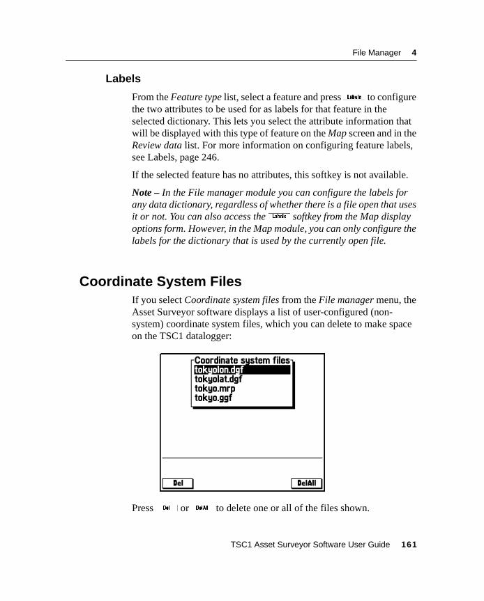
File Manager 4
4.7.4 Labels
From the Feature type list, select a feature and press\ to configurethe two attributes to be used for as labels for that feature in theselected dictionary. This lets you select the attribute information thatwill be displayed with this type of feature on the Map screen and in theReview data list. For more information on configuring feature labels,see Labels, page 246.
If the selected feature has no attributes, this softkey is not available.
Note – In the File manager module you can configure the labels forany data dictionary, regardless of whether there is a file open that usesit or not. You can also access the\ softkey from the Map displayoptions form. However, in the Map module, you can only configure thelabels for the dictionary that is used by the currently open file.
4.8 Coordinate System FilesIf you select Coordinate system files from the File manager menu, theAsset Surveyor software displays a list of user-configured (non-system) coordinate system files, which you can delete to make spaceon the TSC1 datalogger:
Pressd orD to delete one or all of the files shown.
TSC1 Asset Surveyor Software User Guide 161

4 File Manager
162 TSC1 Asset Surveyor Software User Guide

C H A P T E R
5
5 Configuring the AssetSurveyor SoftwareIn this chapter:■ Introduction
■ GPS rover options
■ GPS base station options
■ Coordinate system
■ Map display options
■ Navigation options
■ Units and display
■ Time and date
■ Quickmarks
■ Constant offset
■ External sensors
■ TSC1 hardware
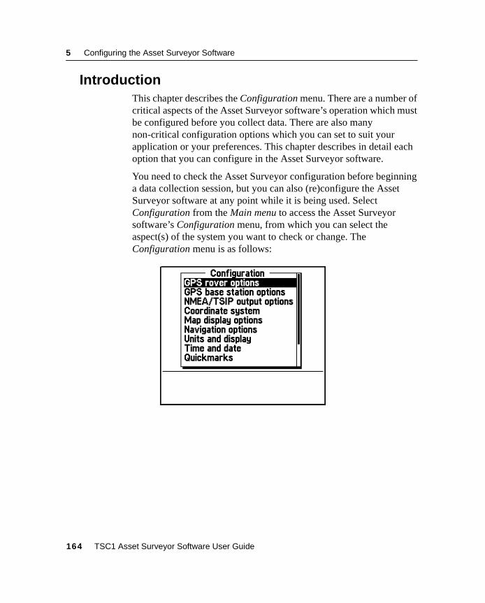
5 Configuring the Asset Surveyor Software
5.1 IntroductionThis chapter describes the Configuration menu. There are a number ofcritical aspects of the Asset Surveyor software’s operation which mustbe configured before you collect data. There are also manynon-critical configuration options which you can set to suit yourapplication or your preferences. This chapter describes in detail eachoption that you can configure in the Asset Surveyor software.
You need to check the Asset Surveyor configuration before beginninga data collection session, but you can also (re)configure the AssetSurveyor software at any point while it is being used. SelectConfiguration from the Main menu to access the Asset Surveyorsoftware’s Configuration menu, from which you can select theaspect(s) of the system you want to check or change. TheConfiguration menu is as follows:
164 TSC1 Asset Surveyor Software User Guide
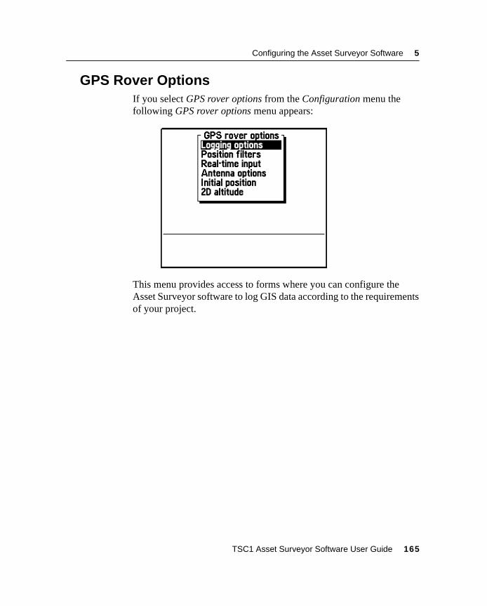
Configuring the Asset Surveyor Software 5
5.2 GPS Rover OptionsIf you select GPS rover options from the Configuration menu thefollowing GPS rover options menu appears:
This menu provides access to forms where you can configure theAsset Surveyor software to log GIS data according to the requirementsof your project.
TSC1 Asset Surveyor Software User Guide 165
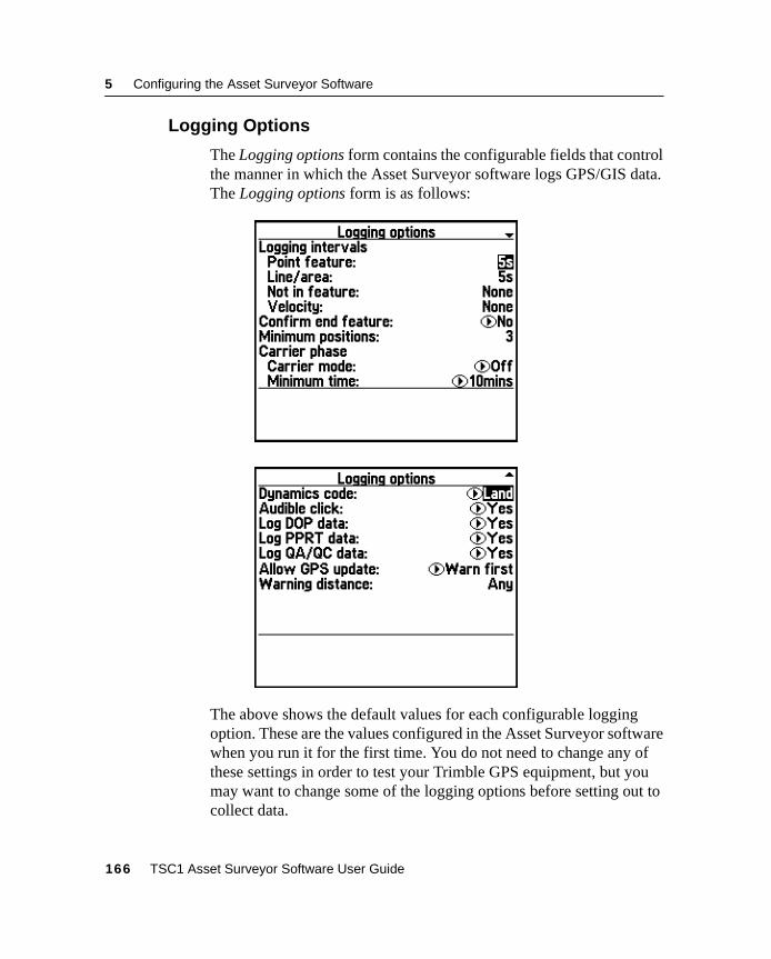
5 Configuring the Asset Surveyor Software
5.2.1 Logging Options
The Logging options form contains the configurable fields that controlthe manner in which the Asset Surveyor software logs GPS/GIS data.The Logging options form is as follows:
The above shows the default values for each configurable loggingoption. These are the values configured in the Asset Surveyor softwarewhen you run it for the first time. You do not need to change any ofthese settings in order to test your Trimble GPS equipment, but youmay want to change some of the logging options before setting out tocollect data.
166 TSC1 Asset Surveyor Software User Guide
Configuring the Asset Surveyor Software 5
Note – The Log PPRT data and Log QA/QC data fields do not appearif you are currently connected to a GPS receiver that does not supportthese modes.
Note – The Carrier phase sub-heading and the Carrier mode andMinimum time fields do not appear if you are connected to a GPSreceiver that does not support logging of carrier phase data.
Note – The Warning distance field does not appear unless Allow GPSupdate is set to ‘Warn First’.
The following sections describe each configurable logging option indetail.
Logging intervals
The Logging intervals heading refers to the following fourconfiguration options, which specify intervals (periods of time)between the logging of various types of information, in varyingcircumstances.
• Point feature: The interval between logged GPS positions whenyou are collecting a point feature. The default logging intervalfor point features is five seconds. This means that when youstart a point feature, the Asset Surveyor software logs GPSpositions once every five seconds, until you end the feature.
• Line/area: The interval between logged GPS positions whenyou are collecting a line or area feature. The default logginginterval for line and area features is five seconds. This meansthat when you start a line or area feature, the Asset Surveyorsoftware logs positions once every five seconds, until you endthe feature. The Asset Surveyor software also logs a GPSposition immediately after starting the feature and just beforeending it.
TSC1 Asset Surveyor Software User Guide 167
5 Configuring the Asset Surveyor Software
• Not in feature: Although most of the GPS data that you log isprobably associated with a feature (that is, a point, line or area),you can use the Asset Surveyor software to log GPS positionsbetween features, so that your final data file contains a trailshowing where you went during the data collection session. Bydefault, the Asset Surveyor software does not log positionsunless in a feature, so the Not in feature logging interval has thedefault value ‘None’.
• Velocity: You can request the Asset Surveyor software to logyour velocity at regular intervals by setting the Velocity optionto a value other than ‘None’ (the default).
Velocities might be logged in order to map and analyze trafficflow, or to show that you performed a data collection session ata constant velocity (for example, when required to traverse aregion at a certain optimal speed in order to conduct otherexperiments).
Recent enhancements to the GPS Pathfinder Office processingsoftware enable the differential correction of velocities loggedfrom GPS Pathfinder receivers. Corrected velocities can beused by the GPS Pathfinder Office software to slightly increasethe accuracy of differentially corrected positions.
Note – Velocities logged from the Series 4000, GPS TotalStation 4800, and Site Surveyor 4400 receivers cannot currentlybe differentially corrected.
Note – You can change the logging intervals at any time, even whenyou are already logging a feature.
B Tip – When you are editing an interval field, the Asset Surveyor softwaremakes two softkeys,0 and7 , available. Press0 to specifythat you want every available GPS position to be logged. Press7 toindicate that you want no positions to be logged.
168 TSC1 Asset Surveyor Software User Guide
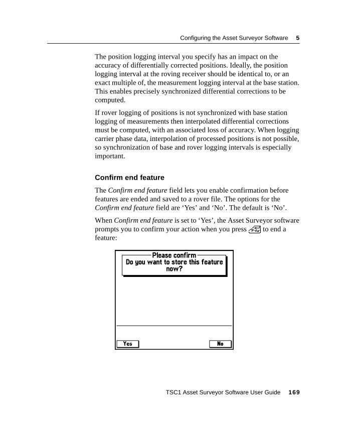
Configuring the Asset Surveyor Software 5
The position logging interval you specify has an impact on theaccuracy of differentially corrected positions. Ideally, the positionlogging interval at the roving receiver should be identical to, or anexact multiple of, the measurement logging interval at the base station.This enables precisely synchronized differential corrections to becomputed.
If rover logging of positions is not synchronized with base stationlogging of measurements then interpolated differential correctionsmust be computed, with an associated loss of accuracy. When loggingcarrier phase data, interpolation of processed positions is not possible,so synchronization of base and rover logging intervals is especiallyimportant.
Confirm end feature
The Confirm end feature field lets you enable confirmation beforefeatures are ended and saved to a rover file. The options for theConfirm end feature field are ‘Yes’ and ‘No’. The default is ‘No’.
When Confirm end feature is set to ‘Yes’, the Asset Surveyor softwareprompts you to confirm your action when you press\ to end afeature:
TSC1 Asset Surveyor Software User Guide 169
5 Configuring the Asset Surveyor Software
Pressy to end the current feature and save it to the rover file, pressn or= to continue logging GPS positions to that feature. Bysetting Confirm end feature to ‘Yes’, you make sure that features arenever ended and saved to the rover file unintentionally.
Minimum positions
In order to obtain the best GPS accuracy for a point feature, remain atthat feature for some time, logging a number of GPS positions. If thesepositions are subsequently differentially corrected and averaged, theaverage position is better than a single GPS position. Certainoccupation periods are recommended in order to obtain varyingdegrees of accuracy with a given GPS receiver (subject to prevailingGPS conditions). However, with a Pro XL, Pro XR, or Pro XRSsystem, you can obtain submeter accuracy with a single position.
Note – For up-to-date information on recommended occupation times,see the most recent documentation or release notes associated withyour specific Trimble GPS receiver.
170 TSC1 Asset Surveyor Software User Guide
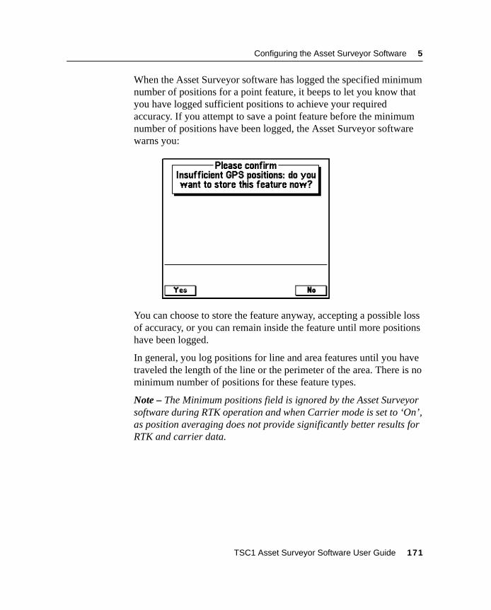
Configuring the Asset Surveyor Software 5
When the Asset Surveyor software has logged the specified minimumnumber of positions for a point feature, it beeps to let you know thatyou have logged sufficient positions to achieve your requiredaccuracy. If you attempt to save a point feature before the minimumnumber of positions have been logged, the Asset Surveyor softwarewarns you:
You can choose to store the feature anyway, accepting a possible lossof accuracy, or you can remain inside the feature until more positionshave been logged.
In general, you log positions for line and area features until you havetraveled the length of the line or the perimeter of the area. There is nominimum number of positions for these feature types.
Note – The Minimum positions field is ignored by the Asset Surveyorsoftware during RTK operation and when Carrier mode is set to ‘On’,as position averaging does not provide significantly better results forRTK and carrier data.
TSC1 Asset Surveyor Software User Guide 171
5 Configuring the Asset Surveyor Software
Carrier phase
The Carrier phase subheading contains two fields relating to thelogging of carrier phase measurements for high accuracy datacollection. These fields are Carrier mode and Minimum time.
For more information on using carrier phase data for high accuracydata collection, see Chapter 7, Carrier Phase Data Collection, in theTSC1 Asset Surveyor Operation Manual.
Note – The Carrier phase subheading, Carrier mode field, andMinimum time field do not appear if you are connected to a GPSreceiver which does not support logging of carrier phase data.
Carrier mode
The Carrier mode field enables the recording of carrier measurementsto the rover file. The options available are ‘On’, and ‘Off’ (default).‘On’ sets the Asset Surveyor software to log synchronized carriermeasurements with each position collected for a feature. ‘Off’ sets theAsset Surveyor software to log code-phase data only.
For a more detailed explanation of the Carrier mode field, seeChapter 7, Carrier Phase Data Collection, in the TSC1 Asset SurveyorOperation Manual.
Minimum time
The Minimum time field lets you set the minimum amount of time thatyou want to collect carrier phase information. There are four availableoptions ranging from 10 to 45 minutes.
In order to obtain the best carrier phase precision, you should collectenough carrier phase information for the Differential Correction utilityin the GPS Pathfinder Office software to compute high accuracypositions. Generally, the longer the block of continuous carrier data,the greater the precision of the features that are collected within it.Features collected within a block of carrier data that exceeds the timeset in the Minimum time field achieve a level of precision relative tothis time.
172 TSC1 Asset Surveyor Software User Guide
Configuring the Asset Surveyor Software 5
For a more detailed explanation of the Minimum time field and thesignificance of carrier data blocks, see Chapter 7, Carrier Phase DataCollection in the TSC1 Asset Surveyor Operation Manual.
Note – Trimble recommends that you switch your Position modesetting to ‘Overdetermined 3D’ when logging carrier phase data.
Dynamics code
The Dynamics code field lets you configure the way in which yourGPS receiver behaves by informing it of your usual mode ofoperation. The Dynamics code helps to control the initial acquisitionof satellites, the subsequent handling of satellite signal obstructions,and the receiver’s behavior in high multipath situations. There arethree available dynamics codes:
These are, of course, general categories into which your applicationmay not necessarily fit. For example, if operating from a balloon, the‘Land’ code, which caters for slow velocity, the occasionalobstruction, and variations in altitude, is better than the ‘Air’ code.
Code Description
Land The default dynamics code, and the best for most GIS datacollection. This code informs the receiver that you are operatingon land, where you may encounter canopy or other obstacleswhich might obscure satellite signals, and where you are movingat a relatively low velocity.
Sea Informs the receiver that you are on the water, at a constantaltitude, where you might also encounter obstructions but areunlikely to be moving at a very high velocity. The receiver catersfor the possibility that its antenna may be mounted on a mastand be moving backwards and forwards reasonably rapidly.
Air Informs the receiver that you are in the air, where you areunlikely to suffer obstruction of satellite signals but where youare likely to be moving at a higher velocity.
TSC1 Asset Surveyor Software User Guide 173
5 Configuring the Asset Surveyor Software
Note – If you configure the Dynamics code incorrectly, this generallydoes not cause significant harm. You may notice a slightly degradedinitial acquisition of satellite signals, and slightly different behaviorwhen satellite signals are obscured.
Note – The Series 4000, GPS Total Station 4800, and Site Surveyor4400 GPS receivers are configured to operate using the ‘Land’dynamics code at all times. The Asset Surveyor software’s Dynamicscode field is completely ignored when connected to the Series 4000,GPS Total Station 4800, and Site Surveyor 4400 GPS receivers.
Audible click
By default, the Asset Surveyor software causes the TSC1 dataloggerto click audibly each time a GPS position is logged. This assures youthat your system is operating normally, without you having to watchthe TSC1 datalogger’s screen. If the clicking stops, then it is likelythat some significant event has occurred (such as a high PDOP value,too few satellites, and so on). Set Audible click to ‘No’ to disableclicking.
Log DOP data
You can choose to log dilution of precision (DOP) values, so that youhave a record of the GPS conditions that prevailed during a mappingsession. These DOP values can be used to provide a degree of qualityassurance, especially if you are collecting data and supplying it undercontract to a third party, which may require evidence that the data wassurveyed carefully and under acceptable GPS conditions.
174 TSC1 Asset Surveyor Software User Guide
Configuring the Asset Surveyor Software 5
When the Log DOP data configurable option is set to ‘Yes’, the AssetSurveyor software logs values of PDOP, HDOP, VDOP, and TDOPwhenever the PDOP value varies by 0.1 or more, provided the PDOPis below the configured PDOP mask. This provides a good record ofeach DOP situation which occurred throughout a data collectionsession. The logging of DOP information increases the size of the datafile by up to 10%, depending on the number of constellation changesdue to satellites being frequently obstructed (for example, whendriving near trees or buildings).
Note – The Trimble Series 4000 GPS receivers do not provide TDOPinformation, so the TDOP values logged by the Asset Surveyorsoftware are always 0.0 when connected to a Series 4000 receiver.
The default setting for Log DOP data is ‘Yes’.
Log PPRT data
With the Pro XR and Pro XRS receivers, you can elect to logadditional data so that GPS positions which were corrected in real-time (RTCM) can be reprocessed in the office, provided you haveaccess to a base station which logs data for postprocessing.Postprocessing of RTCM-corrected GPS positions is worthwhile if thereal-time base station you are using is a considerable distance fromwhere you are collecting data (and your postprocessing base station isnearer), or if the real-time base station which you are using isinaccurate for other reasons (such as a slow update rate).
Logging of PPRT (Postprocessed Real-time) data approximatelyhalves the number of RTCM-corrected GPS positions which you canstore in the memory of your datalogger.
Note – The Log PPRT data option does not appear if you areconnected to a GPS receiver other than the Pathfinder Pro XR orPro XRS.
The default setting for Log PPRT data is ‘Yes’.
TSC1 Asset Surveyor Software User Guide 175
5 Configuring the Asset Surveyor Software
Log QA/QC data
The Log QA/QC data field enables the logging of any QA/QC(Quality Assurance/Quality Control) data that is being sent by thereceiver. You can choose to log QA/QC records to provide a degree ofquality assurance for the position data you have collected. EnablingQA/QC logging also lets you filter positions according to precisionbefore exporting them to a GIS.
The options for the Log QA/QC data field are ‘Yes’ and ‘No’. Thedefault setting for Log QA/QC data is ‘Yes’.
For more information about using QA/QC record information, refer tothe RTK for Mapping and GIS General Reference manual.
Allow GPS update
The Allow GPS update field controls whether a feature’s GPS positioncan be updated. The options for this field are ‘Always’ to allow updateunder any circumstances, ‘Never’ to prohibit it, and ‘Warn first’ todisplay a warning message before update of GPS positions begins.
The default setting for Allow GPS update is ‘Warn first’.
Warning distance
If you set the Allow GPS update field to ‘Warn first’, the Warningdistance field appears. You can select ‘Any’, to display the warningmessage before any GPS update, or enter a distance. If you enter adistance, the warning message only appears if you are further than thisdistance from the original GPS start position of the feature.
The default setting for Warning distance is ‘Any’.
176 TSC1 Asset Surveyor Software User Guide
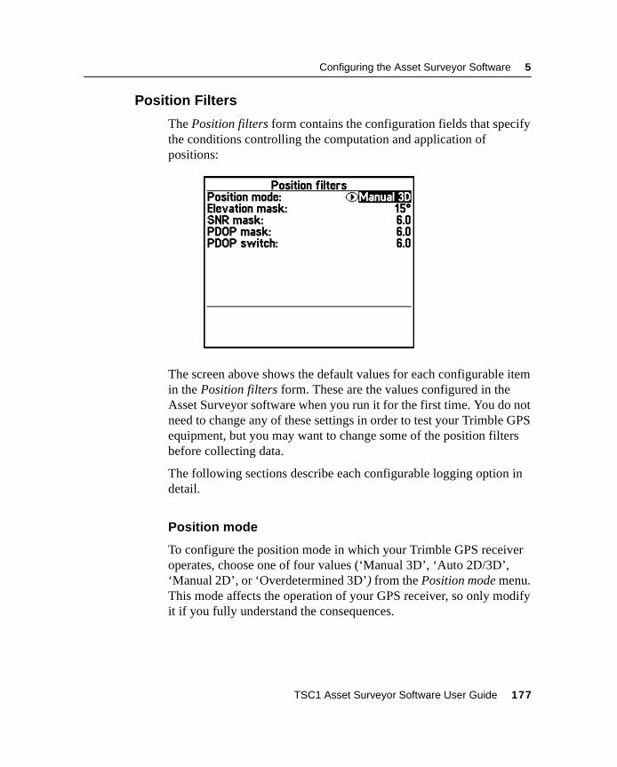
Configuring the Asset Surveyor Software 5
5.2.2 Position Filters
The Position filters form contains the configuration fields that specifythe conditions controlling the computation and application ofpositions:
The screen above shows the default values for each configurable itemin the Position filters form. These are the values configured in theAsset Surveyor software when you run it for the first time. You do notneed to change any of these settings in order to test your Trimble GPSequipment, but you may want to change some of the position filtersbefore collecting data.
The following sections describe each configurable logging option indetail.
Position mode
To configure the position mode in which your Trimble GPS receiveroperates, choose one of four values (‘Manual 3D’, ‘Auto 2D/3D’,‘Manual 2D’, or ‘Overdetermined 3D’) from the Position mode menu.This mode affects the operation of your GPS receiver, so only modifyit if you fully understand the consequences.
TSC1 Asset Surveyor Software User Guide 177
5 Configuring the Asset Surveyor Software
The four modes are described below.
• ‘Manual 3D’: This is the default mode. Your Trimble GPSreceiver uses as many satellites as it is capable of using (but atleast 4) to compute positions. This usually yields the mostaccurate GPS positions and is the most flexible mode in whichthe receiver can be operated. If your GPS receiver is capable ofcomputing overdetermined GPS positions, it does so in Manual3D mode when there are more than four satellites available.
You should always use Manual 3D mode or forcedOverdetermined 3D mode in order to achieve a high level ofaccuracy for logged positions.
• ‘Auto 2D/3D’: In Auto 2D/3D mode, your Trimble GPSreceiver uses four satellites to compute GPS positions when it isable to, but when the number of visible satellites falls to three, itcontinues to compute positions, using the last known altitude. Aposition computed when there are only three usable satellites iscalled a two-dimensional position, and the accuracy of twodimensional positions is crucially affected by the accuracy ofthe altitude.
In Auto 2D/3D mode, when the GPS receiver switches to 2Dmode (that is, when there are only three usable satellites), it usesthe altitude of the last available 3D position, or any altitude thatyou have entered manually since the last 3D position wascomputed. You can manually enter a 2D altitude by selecting2D altitude from the GPS rover options menu.
If you are operating in conditions where satellite visibility ispoor and you can determine your altitude above the WGS-84ellipsoid very accurately at all times, then you may want to tryAuto 2D/3D mode. However, there is a high probability thatyour data is not always very accurate due to altitude inputerrors.
178 TSC1 Asset Surveyor Software User Guide
Configuring the Asset Surveyor Software 5
C Warning – If you use Auto 2D/3D mode and specify an inaccuratealtitude, this has a significant impact on the position computed by yourGPS receiver. As a rule, every meter of error in the altitude you supply willcause at least three meters of error in the position computed by your GPSreceiver.
Note – The Pro XR, Pro XRS, 4600LS, Site Surveyor 4400, GPSTotal Station 4800, and Series 4000 GPS receivers supportoverdetermined 2D mode, meaning that they can use four ormore satellites to compute a 2D solution. When the Positionmode is set to ‘Auto 2D/3D’, this occurs in circumstances whenthe 3D PDOP exceeds the configured PDOP mask, but theoverdetermined 2D PDOP is below the PDOP mask.
• ‘Manual 2D’: In Manual 2D mode, a Pathfinder GPS receiveralways uses the best three satellites available, even if there arefour or more which could be used for computing positions. Youmust supply an accurate altitude above the WGS-84 ellipsoidbefore using Manual 2D mode. This mode is useful if you areabsolutely sure of your altitude above the WGS-84 ellipsoid, asit avoids the inaccuracies experienced in Auto 2D/3D modewhen the GPS receiver switches from using a 3D altitudeobtained from GPS to using the 2D altitude that you supply.Unless you are operating exclusively at the same altitude, youmust manually enter a new altitude whenever you move up ordown.
C Warning – If you use Manual 2D mode and specify an inaccurate altitude,this has a significant impact on the position computed by your GPSreceiver. As a rule, every meter of error in the altitude you supply willcause at least three meters of error in the position computed by your GPSreceiver.
TSC1 Asset Surveyor Software User Guide 179
5 Configuring the Asset Surveyor Software
Note – The Pro XR, Pro XRS, 4600LS, Site Surveyor 4400, GPSTotal Station 4800, and Series 4000 GPS receivers supportoverdetermined 2D mode, meaning that they can use four ormore satellites to compute a 2D solution. When the Positionmode is set to ‘Manual 2D’, the Series 4000 GPS receiver usesas many satellites as it can to compute an overdetermined 2Dposition.
• ‘Overdetermined 3D’: In Overdetermined 3D mode, yourTrimble GPS receiver uses as many satellites as it can tocompute positions. These GPS positions are logged only if thereare at least five satellites available, so that all logged positionsare forced to be overdetermined. This yields the most accurateGPS positions. It is the recommended mode when loggingcarrier phase data.
Elevation mask
You can restrict your Trimble GPS receiver to using only thosesatellites above a certain elevation in the sky by imposing an Elevationmask. The default elevation masks recommended by Trimble are 15°for rovers and 10° for base stations. This difference ensures that a basestation can always ‘see’ all of the satellites which can be seen by anyrovers. If you choose to alter the rover elevation mask, make sure thatyour base station (if any) still has a lower mask, so that you can stilldifferentially correct data files collected by that rover.
There is rarely a need to use an elevation mask lower than 15°, giventhe number of GPS satellites in service, but if you do decide to loweryour elevation mask(s), be aware that the increased ionospheric noiseassociated with satellites low on the horizon can easily counter anyimprovement in PDOP given by a lower elevation mask. Additionally,the effects of multipath increase as lower satellites are used.
180 TSC1 Asset Surveyor Software User Guide
Configuring the Asset Surveyor Software 5
C Warning – You must make sure that the elevation mask for a rover is sethigher than the base station so that the base station always tracks anysatellites visible to each rover. Remember that as a rover gets further fromthe base station, the difference between the elevation mask of the roverand the base becomes more and more critical (due to the curvature of theearth). As a rule of thumb, the difference must be at least 1° for every 100km between the base and the rover.
SNR mask
The signal strength of a satellite is a measure of the informationcontent of the signal relative to the signal’s noise. As this proportiondecreases, information gets lost in the noise. The typical signalstrength of a satellite at 30° elevation is between 12.0 and 20.0. Avalue above 20.0 is very good. The quality of a GPS position isdegraded if the signal level of one or more satellites in theconstellation falls below 6.0.
The Asset Surveyor software lets you set a mask, called theSignal-to-Noise Ratio mask (or SNR mask), the value of which is usedto determine whether the signal strength of each satellite is sufficientfor that satellite to be used by the GPS receiver. The default value forthe Asset Surveyor software’s SNR mask is 6.0.
Note – Trimble’s Site Surveyor 4400, GPS Total Station 4800, andSeries 4000 GPS receivers have a fixed internal SNR mask (of 4.0).The Asset Surveyor software’s SNR mask option has no effect on theoperation of the Site Surveyor 4400, GPS Total Station 4800, andSeries 4000 receivers.
C Warning – If you lower the SNR mask, you let your GPS receiver usesatellites with weaker signals. While this may increase the GPS coverageyou can obtain in environments where the GPS signal is weakened (suchas forests), it probably causes a reduction in GPS accuracy.
TSC1 Asset Surveyor Software User Guide 181
5 Configuring the Asset Surveyor Software
PDOP mask and PDOP switch
The accuracy of a position computed by a GPS receiver is essentially afunction of the geometry of the GPS constellation visible at thatmoment in time. When the visible satellites are well separated in thesky, your GPS receiver is able to compute accurate positions. If two ormore satellites are close together in the sky, the small errors inherentin measuring their signals compound, reducing the accuracy ofcomputed positions.
There are several Dilution of Precision (DOP) factors associated withGPS, and these DOP factors express an aspect of the expectedaccuracy of the GPS system. DOP factors are linear multipliers on theexpected error, so a small DOP value is better than a large one. Thebest overall indicator of constellation geometry is known as PositionDilution of Precision, or PDOP.
A PDOP value of 4.0 or less tends to give excellent positionalaccuracy. A PDOP between 4.0 and 8.0 provides acceptable accuracy,while a PDOP of 8.0 or more implies poorer accuracy. When satellitesnearly line up in the sky, the PDOP values can briefly go into thehundreds or even thousands, and for those periods computed GPSpositions may be quite inaccurate.
The Asset Surveyor software lets you specify a PDOP mask, whichthe GPS receiver uses as an upper bound on PDOP values. When thePDOP climbs above this mask, the receiver ceases computing GPSpositions. This enables you to program a desired level of positionalaccuracy, and make sure that any positions which you log are of acertain quality. The default PDOP mask value is 6.0.
Note – Some Trimble GPS systems specify a maximum PDOP of 4.0 inorder to achieve submeter accuracy. The Pro XR and Pro XRSreceivers achieve submeter accuracy with a PDOP of 6.0 or less.
182 TSC1 Asset Surveyor Software User Guide
Configuring the Asset Surveyor Software 5
C Warning – Increasing the PDOP mask lets you log positions for more ofthe time, but position quality may be seriously degraded. It is better toretain a lower PDOP mask and use Trimble’s mission planning software toidentify the brief times of high PDOP, and to schedule other activities (likelunch!) in these times, rather than to continue surveying and compromisethe accuracy of your data collection session. Conversely, you should notreduce your PDOP mask too far below the value recommended for yourparticular Trimble GPS receiver, as this significantly decreases theamount of time you can spend collecting data, without significantlyincreasing the accuracy of your data collection session.
For a more detailed discussion of DOP values, refer to the MappingSystems General Reference manual.
Note – In 2D mode the PDOP mask ought to be set lower than in 3Dmode, as two dimensional PDOP values are inherently smaller thanPDOP values in three dimensions. Despite this difference, 3Dpositions are almost always more accurate than 2D positions due tothe difficulty of accurately specifying your 2D altitude above theWGS-84 ellipsoid.
In addition to the PDOP mask, the Asset Surveyor software provides aPDOP switch configuration option for users of the Auto 2D/3DPosition mode. Unlike the PDOP mask, which determines a cutoffvalue above which GPS positions are not computed, the PDOP switchis the value at which the receiver switches from 3D to 2D mode (thePDOP switch is therefore effectively a PDOP mask for 3D mode, withthe configured PDOP mask being applied in 2D mode).
The default values of the PDOP mask and PDOP switch are the same(6.0), but by altering the value of the PDOP switch, you can force yourGPS receiver to switch to 2D mode (and deliberately ignore one ormore satellites in the process) in order to achieve a lowerPDOP-induced error. Of course, your 2D altitude must be veryaccurately known and entered, otherwise it induces a greater error inyour GPS position than would a higher 3D PDOP.
TSC1 Asset Surveyor Software User Guide 183
5 Configuring the Asset Surveyor Software
5.2.3 Real-Time Input Options
Selecting Real-time input from the Rover options menu leads to theReal-time input options form, where you can configure the operationof your GPS receiver’s real-time correction link. The Asset Surveyorsoftware can be used to receive real-time differential corrections overa radio, modem or other telemetry link (or a geostationary satellite ifyou are using a GPS Pathfinder Pro XRS receiver).
All of the GPS receivers supported by the Asset Surveyor softwareversion 5.20 are capable of real-time input. Some are capable ofreal-time input in several different forms, including RTCM, RTK,beacon and satellite DGPS.
Because you may not always be able to receive real-time correctionsfrom your preferred correction source, you need to specify what theAsset Surveyor software should do when your first choice real-timesource is lost. This can include switching to an alternative source ofcorrections, using autonomous GPS, or suspending logging untilreal-time corrections are reacquired.
To configure real-time input you specify an ordered list of choices thatdetermines what correction source is used, and in what order sourcesare used if you specify more than one. Whenever possible, the AssetSurveyor software uses the first choice, but when this correctionsource is not available, the software switches to the next choice on thelist. If that source becomes unavailable, the software switches to thenext choice, and so on. This list of choices is located in a single form,so it is easy to see what correction options you have selected.
184 TSC1 Asset Surveyor Software User Guide
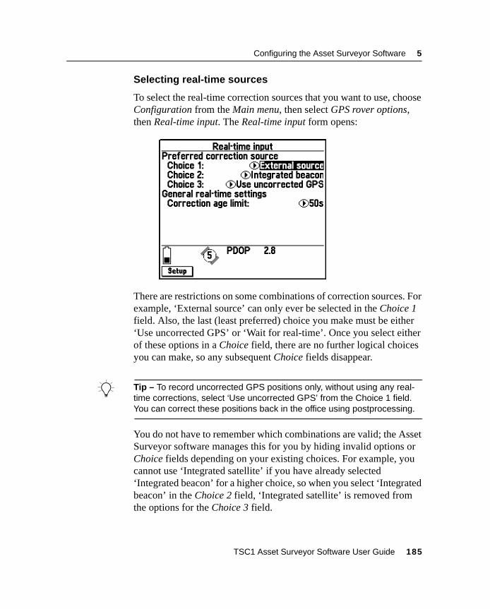
Configuring the Asset Surveyor Software 5
Selecting real-time sources
To select the real-time correction sources that you want to use, chooseConfiguration from the Main menu, then select GPS rover options,then Real-time input. The Real-time input form opens:
There are restrictions on some combinations of correction sources. Forexample, ‘External source’ can only ever be selected in the Choice 1field. Also, the last (least preferred) choice you make must be either‘Use uncorrected GPS’ or ‘Wait for real-time’. Once you select eitherof these options in a Choice field, there are no further logical choicesyou can make, so any subsequent Choice fields disappear.
B Tip – To record uncorrected GPS positions only, without using any real-time corrections, select ‘Use uncorrected GPS’ from the Choice 1 field.You can correct these positions back in the office using postprocessing.
You do not have to remember which combinations are valid; the AssetSurveyor software manages this for you by hiding invalid options orChoice fields depending on your existing choices. For example, youcannot use ‘Integrated satellite’ if you have already selected‘Integrated beacon’ for a higher choice, so when you select ‘Integratedbeacon’ in the Choice 2 field, ‘Integrated satellite’ is removed fromthe options for the Choice 3 field.
TSC1 Asset Surveyor Software User Guide 185
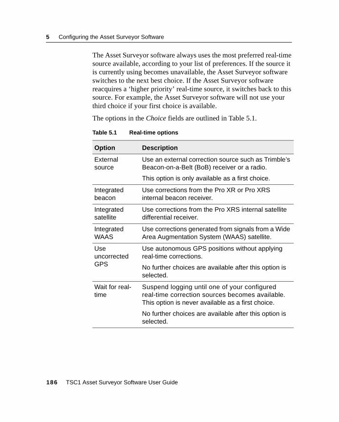
5 Configuring the Asset Surveyor Software
The Asset Surveyor software always uses the most preferred real-timesource available, according to your list of preferences. If the source itis currently using becomes unavailable, the Asset Surveyor softwareswitches to the next best choice. If the Asset Surveyor softwarereacquires a ‘higher priority’ real-time source, it switches back to thissource. For example, the Asset Surveyor software will not use yourthird choice if your first choice is available.
The options in the Choice fields are outlined in Table 5.1.
Table 5.1 Real-time options
Option Description
Externalsource
Use an external correction source such as Trimble’sBeacon-on-a-Belt (BoB) receiver or a radio.
This option is only available as a first choice.
Integratedbeacon
Use corrections from the Pro XR or Pro XRSinternal beacon receiver.
Integratedsatellite
Use corrections from the Pro XRS internal satellitedifferential receiver.
IntegratedWAAS
Use corrections generated from signals from a WideArea Augmentation System (WAAS) satellite.
UseuncorrectedGPS
Use autonomous GPS positions without applyingreal-time corrections.
No further choices are available after this option isselected.
Wait for real-time
Suspend logging until one of your configuredreal-time correction sources becomes available.This option is never available as a first choice.
No further choices are available after this option isselected.
186 TSC1 Asset Surveyor Software User Guide
Configuring the Asset Surveyor Software 5
Configuring real-time sources
Once you have selected the real-time sources you want to use, youmay need to configure each source before you can start collectingdata.
To configure a real-time source, highlight the Choice field that has thissource selected and pressS . Alternatively, highlight a Choice fieldand press the( key to display the pop-up menu of possible values.Highlight the correction source in the menu that you want toconfigure, and pressS . You can use this second method toconfigure choices even when they are not selected for use.
B Tip – You can also configure any selected source by pressingS in thesource’s DGPS status details form in the Receiver status module.
The correction age limit is common to all real-time sources, so it isconfigured from the Real-time input form. Use the Correction agelimit field to set the maximum age (the time that has elapsed since themessage was received) at which a real-time correction message will beused. If no corrections are received after this time, the Asset Surveyorsoftware treats the real-time source as lost and switches to your nextchoice.
Note – There are no configuration fields for the Integrated WAAS, UseFloat Solution (RTCM), Use Uncorrected GPS, or Wait for Real-timeoptions.
When you pressS , the setup form for the selected correctionsource appears. The fields that appear in the form depend on thecorrection source.
TSC1 Asset Surveyor Software User Guide 187
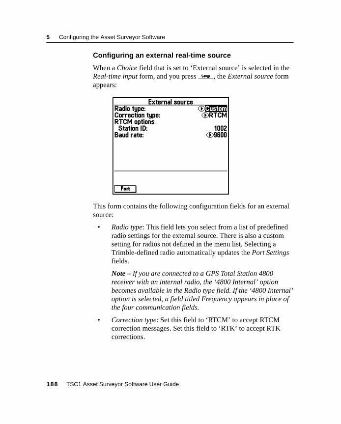
5 Configuring the Asset Surveyor Software
Configuring an external real-time source
When a Choice field that is set to ‘External source’ is selected in theReal-time input form, and you pressS, the External source formappears:
This form contains the following configuration fields for an externalsource:
• Radio type: This field lets you select from a list of predefinedradio settings for the external source. There is also a customsetting for radios not defined in the menu list. Selecting aTrimble-defined radio automatically updates the Port Settingsfields.
Note – If you are connected to a GPS Total Station 4800receiver with an internal radio, the ‘4800 Internal’ optionbecomes available in the Radio type field. If the ‘4800 Internal’option is selected, a field titled Frequency appears in place ofthe four communication fields.
• Correction type: Set this field to ‘RTCM’ to accept RTCMcorrection messages. Set this field to ‘RTK’ to accept RTKcorrections.
188 TSC1 Asset Surveyor Software User Guide
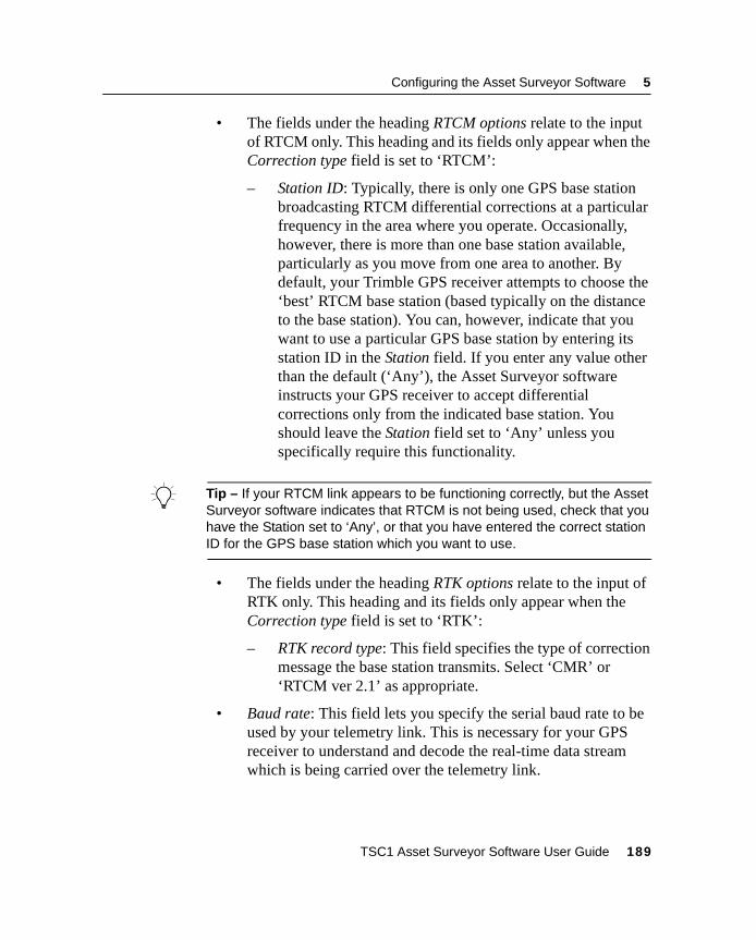
Configuring the Asset Surveyor Software 5
• The fields under the heading RTCM options relate to the inputof RTCM only. This heading and its fields only appear when theCorrection type field is set to ‘RTCM’:
– Station ID: Typically, there is only one GPS base stationbroadcasting RTCM differential corrections at a particularfrequency in the area where you operate. Occasionally,however, there is more than one base station available,particularly as you move from one area to another. Bydefault, your Trimble GPS receiver attempts to choose the‘best’ RTCM base station (based typically on the distanceto the base station). You can, however, indicate that youwant to use a particular GPS base station by entering itsstation ID in the Station field. If you enter any value otherthan the default (‘Any’), the Asset Surveyor softwareinstructs your GPS receiver to accept differentialcorrections only from the indicated base station. Youshould leave the Station field set to ‘Any’ unless youspecifically require this functionality.
B Tip – If your RTCM link appears to be functioning correctly, but the AssetSurveyor software indicates that RTCM is not being used, check that youhave the Station set to ‘Any’, or that you have entered the correct stationID for the GPS base station which you want to use.
• The fields under the heading RTK options relate to the input ofRTK only. This heading and its fields only appear when theCorrection type field is set to ‘RTK’:
– RTK record type: This field specifies the type of correctionmessage the base station transmits. Select ‘CMR’ or‘RTCM ver 2.1’ as appropriate.
• Baud rate: This field lets you specify the serial baud rate to beused by your telemetry link. This is necessary for your GPSreceiver to understand and decode the real-time data streamwhich is being carried over the telemetry link.
TSC1 Asset Surveyor Software User Guide 189
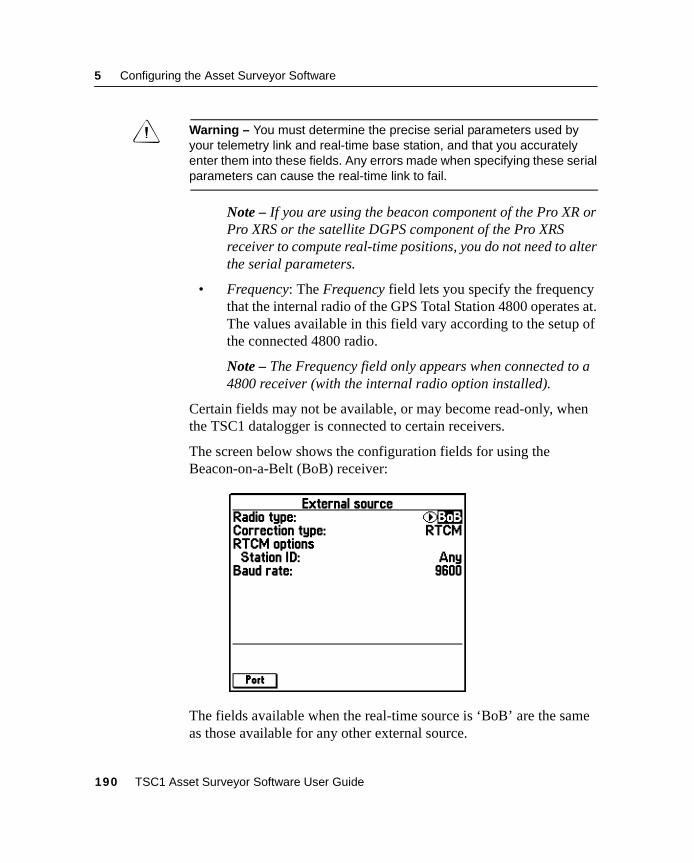
5 Configuring the Asset Surveyor Software
C Warning – You must determine the precise serial parameters used byyour telemetry link and real-time base station, and that you accuratelyenter them into these fields. Any errors made when specifying these serialparameters can cause the real-time link to fail.
Note – If you are using the beacon component of the Pro XR orPro XRS or the satellite DGPS component of the Pro XRSreceiver to compute real-time positions, you do not need to alterthe serial parameters.
• Frequency: The Frequency field lets you specify the frequencythat the internal radio of the GPS Total Station 4800 operates at.The values available in this field vary according to the setup ofthe connected 4800 radio.
Note – The Frequency field only appears when connected to a4800 receiver (with the internal radio option installed).
Certain fields may not be available, or may become read-only, whenthe TSC1 datalogger is connected to certain receivers.
The screen below shows the configuration fields for using theBeacon-on-a-Belt (BoB) receiver:
The fields available when the real-time source is ‘BoB’ are the sameas those available for any other external source.
190 TSC1 Asset Surveyor Software User Guide
Configuring the Asset Surveyor Software 5
Port settings
When you select an option from the Radio type field in the Externalsource form, the correct port settings for that radio type areautomatically selected. To view or edit the current settings, pressMin the External source form. The General port settings form appears:
Note – You cannot edit port settings while you are using a BoBreceiver as your external correction source.
These port settings also apply when transmitting NMEA or TSIPmessages. When you change general port settings for one of theseoptions, you also change the settings for the other option.
You can also open the General port settings form from theNMEA/TSIP output options form. However, the software does not letyou have two copies of the General port settings form open at thesame time.
Because changes to your selected real-time sources or theirconfiguration can also affect the port settings, the software alsoprevents you from opening both the General port settings form andany real-time configuration form that could change port settings.
TSC1 Asset Surveyor Software User Guide 191
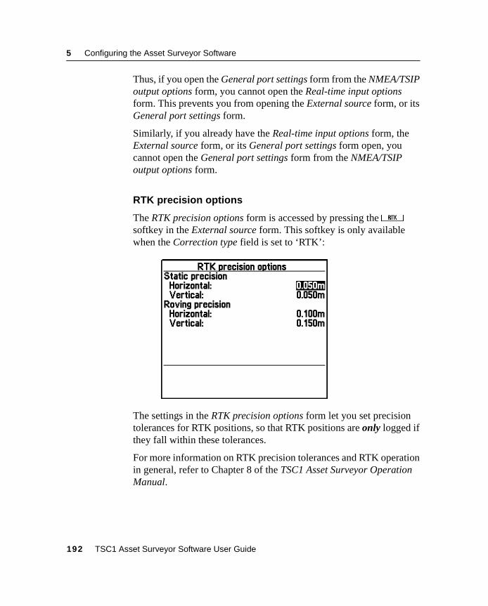
5 Configuring the Asset Surveyor Software
Thus, if you open the General port settings form from the NMEA/TSIPoutput options form, you cannot open the Real-time input optionsform. This prevents you from opening the External source form, or itsGeneral port settings form.
Similarly, if you already have the Real-time input options form, theExternal source form, or its General port settings form open, youcannot open the General port settings form from the NMEA/TSIPoutput options form.
RTK precision options
The RTK precision options form is accessed by pressing theRsoftkey in the External source form. This softkey is only availablewhen the Correction type field is set to ‘RTK’:
The settings in the RTK precision options form let you set precisiontolerances for RTK positions, so that RTK positions are only logged ifthey fall within these tolerances.
For more information on RTK precision tolerances and RTK operationin general, refer to Chapter 8 of the TSC1 Asset Surveyor OperationManual.
192 TSC1 Asset Surveyor Software User Guide
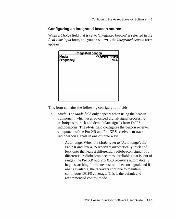
Configuring the Asset Surveyor Software 5
Configuring an integrated beacon source
When a Choice field that is set to ‘Integrated beacon’ is selected in theReal-time input form, and you pressS, the Integrated beacon formappears:
This form contains the following configuration fields:
• Mode: The Mode field only appears when using the beaconcomponent, which uses advanced digital-signal processingtechniques to track and demodulate signals from DGPSradiobeacons. The Mode field configures the beacon receivercomponent of the Pro XR and Pro XRS receivers to trackradiobeacon signals in one of three ways:
– Auto range: When the Mode is set to ‘Auto range’, thePro XR and Pro XRS receivers automatically track andlock onto the nearest differential radiobeacon signal. If adifferential radiobeacon becomes unreliable (that is, out ofrange), the Pro XR and Pro XRS receivers automaticallybegin searching for the nearest radiobeacon signal, and ifone is available, the receivers continue to maintaincontinuous DGPS coverage. This is the default andrecommended control mode.
TSC1 Asset Surveyor Software User Guide 193
5 Configuring the Asset Surveyor Software
– Auto power: When the Mode is set to ‘Auto power’, thePro XR and Pro XRS receivers automatically track andlock onto the differential radiobeacon signal that isdetected as being the most powerful. If a differentialradiobeacon becomes unreliable (that is, becomes tooweak), the Pro XR and Pro XRS receivers automaticallybegin searching for the most powerful radiobeacon signal,and if one is available, the receivers continue to maintaincontinuous DGPS coverage.
Note – If the receiver is tracking more than one beaconsignal, it locks onto the signal that is transmitted by areference station using an integrity monitor, even if it isfurther away or has a weaker signal than a signaltransmitted by a reference station that is not using anintegrity monitor.
– Manual: When the Mode is set to ‘Manual’, the Pro XRand Pro XRS receivers use only the radiobeacon frequencyyou specify in the Frequency field. If the differentialradiobeacon transmitting on the specified frequencybecomes unreliable, the warning message Radio link downflashes in the status line. From this point forward, thereceiver computes and stores positions without real-timecorrections being applied, until either the receiver locksonto the specified frequency again or until a new frequencyis specified.
• Frequency: This field lists the frequency of the DGPS MSKradiobeacon or DGPS satellite that the receivers track to receiveRTCM corrections.
194 TSC1 Asset Surveyor Software User Guide
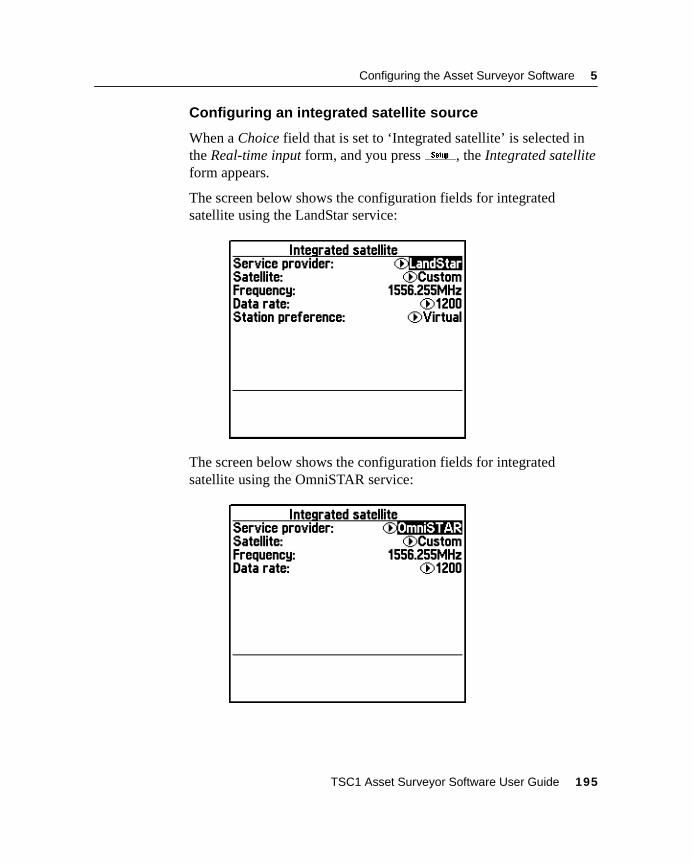
Configuring the Asset Surveyor Software 5
Configuring an integrated satellite source
When a Choice field that is set to ‘Integrated satellite’ is selected inthe Real-time input form, and you pressS, the Integrated satelliteform appears.
The screen below shows the configuration fields for integratedsatellite using the LandStar service:
The screen below shows the configuration fields for integratedsatellite using the OmniSTAR service:
TSC1 Asset Surveyor Software User Guide 195
5 Configuring the Asset Surveyor Software
The following fields are available in the Integrated satellite form:
• Service provider: There are two service providers you can use toreceive satellite DGPS signals. These are ‘LandStar’ and‘OmniSTAR’. For more details of these services, see the ProXR/XRS Receiver Manual.
• Satellite: This lists the DGPS satellites by name that thereceiver can track. Select the appropriate satellite for the areayou are collecting data within. For more details of each satelliteand the area each covers, see the Pro XR/XRS Receiver Manual.
• Frequency: This lists the frequency of the DGPS MSKradiobeacon that the receivers track for RTCM corrections.
• Data rate: This lists the data rate of the satellite DGPS signal.Some satellites output DGPS signals at a different rate fromothers, and this field needs to be configured correctly in order toreceive the signals. This field is automatically updated whenyou select a predefined satellite from the Satellite field. If youhave selected ‘Custom’ in the Satellite field, you may need toconfigure the Data rate.
Note – The details for the Satellite, Frequency, and Data ratefields are sourced from the file SatDGPS.ini. You can get anup-to-date version of this file from Trimble’s ftp site (atftp://ftp.trimble.com or fromhttp://www.trimble.com/support/support.htm) and transfer it tothe Asset Surveyor software to provide the most recent detailsfor DGPS satellites and their frequencies. For details ontransferring files to the Asset Surveyor software, see FileTransfer, page 152.
196 TSC1 Asset Surveyor Software User Guide
Configuring the Asset Surveyor Software 5
• Station preference: When ‘LandStar’ is selected as the Serviceprovider the Integrated satellite form displays the Stationpreference field. The Station preference field enables you tospecify the type of reference station that you prefer to use toobtain satellite DGPS corrections. The options for the Stationpreference field are ‘Virtual’ (the default) and ‘Closest’.‘Virtual’ sets the GPS receiver to compute DGPS correctionsusing a ‘virtual’ reference station position. A virtual referencestation position is an interpolated position that is derived fromthe centroid of the reference station network. It provides areference position based on the approximate position of yourroving receiver. ‘Closest’ sets the GPS receiver to computeDGPS corrections using the nearest reference station position.This may be an ‘actual’ reference station, a ‘cell’ referencestation (an interpolated fixed reference position), or the networkcentroid (a position representing the centroid of the referencestation network).
Note – The Station preference field is only available when‘LandStar’ is selected as the Service provider.
Note – Trimble recommends setting the Station preference fieldto ‘Virtual’ where possible. Setting the Station preference fieldto ‘Closest’ may be used when the GPS receiver is used on thefringe of a satellite reference station network where thetransmission of corrections may be intermittent.
TSC1 Asset Surveyor Software User Guide 197
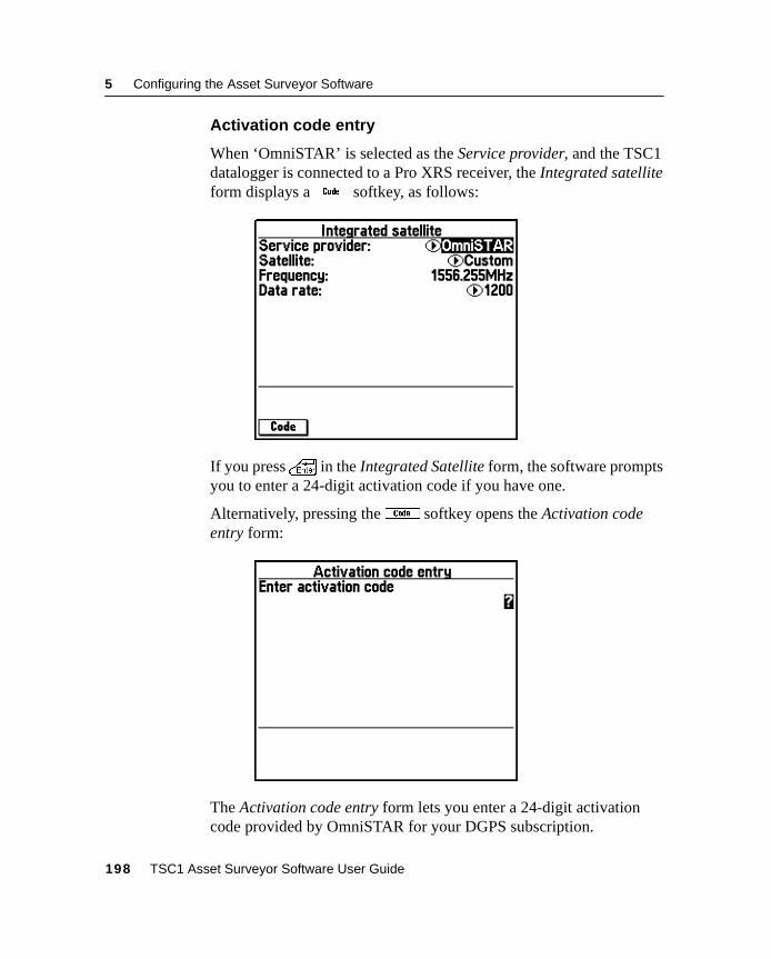
5 Configuring the Asset Surveyor Software
Activation code entry
When ‘OmniSTAR’ is selected as the Service provider, and the TSC1datalogger is connected to a Pro XRS receiver, the Integrated satelliteform displays a% softkey, as follows:
If you press\ in the Integrated Satellite form, the software promptsyou to enter a 24-digit activation code if you have one.
Alternatively, pressing the% softkey opens the Activation codeentry form:
The Activation code entry form lets you enter a 24-digit activationcode provided by OmniSTAR for your DGPS subscription.
198 TSC1 Asset Surveyor Software User Guide
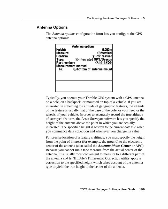
Configuring the Asset Surveyor Software 5
5.2.4 Antenna Options
The Antenna options configuration form lets you configure the GPSantenna options:
Typically, you operate your Trimble GPS system with a GPS antennaon a pole, on a backpack, or mounted on top of a vehicle. If you areinterested in collecting the altitude of geographic features, the altitudeof the feature is usually that of the base of the pole, or your feet, or thewheels of your vehicle. In order to accurately record the true altitudeof surveyed features, the Asset Surveyor software lets you specify theheight of the antenna above the point in which you are actuallyinterested. The specified height is written to the current data file whenyou commence data collection and whenever you change its value.
For precise location of a feature’s altitude, you must specify the heightfrom the point of interest (for example, the ground) to the electroniccenter of the antenna (also called the Antenna Phase Center or APC).Because you cannot run a tape measure from the actual center of theantenna, it is usually most convenient to measure to a different part ofthe antenna and let Trimble’s Differential Correction utility apply acorrection to the specified height which takes account of the antennatype to yield the true height to the center of the antenna.
TSC1 Asset Surveyor Software User Guide 199
5 Configuring the Asset Surveyor Software
A measured antenna height is said to be vertical if it is the true heightfrom the point of interest to the center of the antenna, or uncorrectedif it is the height from the point of interest to some designatedmeasuring point on the exterior of the antenna.
The fields in the Antenna options form are:
• The antenna Height is the height from the point of interest(typically on the ground) to the antenna. Whether this is avertical or uncorrected height is determined by the followingfield. The Height field has attached units, which can be alteredby changing the Height units under Units and display. If you areworking in one unit and your antenna pole is calibrated inanother, you can enter a value in whatever units you like; thisvalue is then converted to the units in which you are working.For example, if you enter a height of ‘2 ft 6 in’ when theconfigured Height units are meters, the Asset Surveyor softwareautomatically converts ‘2 ft 6 in’ into ‘0.762 m’.
• The Measure field indicates whether the height has beenmeasured to the antenna’s center (‘Vertical’) or to a point on theantenna’s exterior (‘Uncorrected’).
• The Confirm field indicates whether the antenna height form isdisplayed before starting each feature (‘Per feature’) or file(‘Per file’). If you do not want to be prompted for the antennaheight, select ‘Never’. The default is ‘Per feature’.
• The Type field specifies the antenna being used. Specifying theantenna type enables the Differential Correction utility totransform an uncorrected height to a true vertical height.
200 TSC1 Asset Surveyor Software User Guide
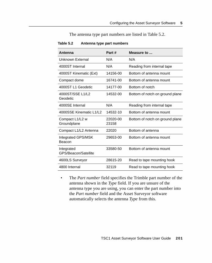
Configuring the Asset Surveyor Software 5
The antenna type part numbers are listed in Table 5.2.
• The Part number field specifies the Trimble part number of theantenna shown in the Type field. If you are unsure of theantenna type you are using, you can enter the part number intothe Part number field and the Asset Surveyor softwareautomatically selects the antenna Type from this.
Table 5.2 Antenna type part numbers
Antenna Part # Measure to ...
Unknown External N/A N/A
4000ST Internal N/A Reading from internal tape
4000ST Kinematic (Ext) 14156-00 Bottom of antenna mount
Compact dome 16741-00 Bottom of antenna mount
4000ST L1 Geodetic 14177-00 Bottom of notch
4000ST/SSE L1/L2Geodetic
14532-00 Bottom of notch on ground plane
4000SE Internal N/A Reading from internal tape
4000SSE Kinematic L1/L2 14532-10 Bottom of antenna mount
Compact L1/L2 wGroundplane
22020-0023158
Bottom of notch on ground plane
Compact L1/L2 Antenna 22020 Bottom of antenna
Integrated GPS/MSKBeacon
29653-00 Bottom of antenna mount
IntegratedGPS/Beacon/Satellite
33580-50 Bottom of antenna mount
4600LS Surveyor 28615-20 Read to tape mounting hook
4800 Internal 32119 Read to tape mounting hook
TSC1 Asset Surveyor Software User Guide 201
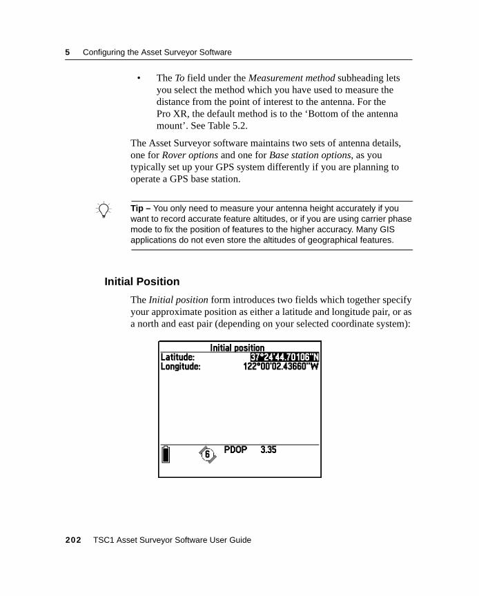
5 Configuring the Asset Surveyor Software
• The To field under the Measurement method subheading letsyou select the method which you have used to measure thedistance from the point of interest to the antenna. For thePro XR, the default method is to the ‘Bottom of the antennamount’. See Table 5.2.
The Asset Surveyor software maintains two sets of antenna details,one for Rover options and one for Base station options, as youtypically set up your GPS system differently if you are planning tooperate a GPS base station.
B Tip – You only need to measure your antenna height accurately if youwant to record accurate feature altitudes, or if you are using carrier phasemode to fix the position of features to the higher accuracy. Many GISapplications do not even store the altitudes of geographical features.
5.2.5 Initial Position
The Initial position form introduces two fields which together specifyyour approximate position as either a latitude and longitude pair, or asa north and east pair (depending on your selected coordinate system):
202 TSC1 Asset Surveyor Software User Guide
Configuring the Asset Surveyor Software 5
When GPS is operating, these fields are kept up to date with thecurrent GPS position. When GPS is not operating, you can consultthese fields to see where you were (or more precisely, where the TSC1datalogger was when it was last used).
The initial position has one important use. Some Trimble GPSreceivers have no internal battery-backed memory of their own (toreduce their weight and to save you having to disassemble themperiodically to change the battery). These receivers must be sent aGPS almanac when they are powered up, so that they can rapidlyacquire signals from satellites and begin to compute GPS positions.Part of a GPS almanac is an approximate initial position, from whichthe GPS receiver can infer the set of satellites that should be visible atany point in time. With a reasonably accurate (that is, ±200–300 km)initial position, the startup time of the GPS receiver should be verygood (30 seconds to 90 seconds, presuming visibility to satellites). Ifthe initial position is very inaccurate (for example, the wrong side ofthe world), startup may take between five and 15 minutes.
If you travel a long way between mapping locations (for example, ifyou fly from one state to another, or from one country to another), youcan ensure a rapid GPS startup by entering an approximate initialposition for your new mapping site.
B Tip – If you do not know your new mapping site’s position, evenapproximately, you need not worry. Just set up your GPS receiver andstart the Asset Surveyor software running. Once your GPS receiver startsto compute positions, its initial position is updated and thereafter restartsat or near that location are rapid.
TSC1 Asset Surveyor Software User Guide 203
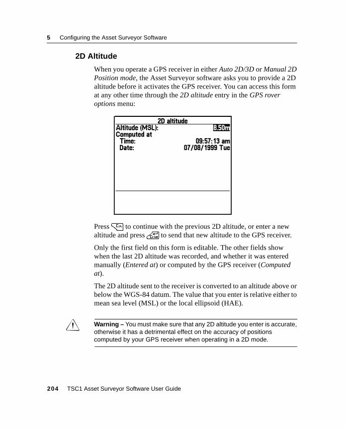
5 Configuring the Asset Surveyor Software
5.2.6 2D Altitude
When you operate a GPS receiver in either Auto 2D/3D or Manual 2DPosition mode, the Asset Surveyor software asks you to provide a 2Daltitude before it activates the GPS receiver. You can access this format any other time through the 2D altitude entry in the GPS roveroptions menu:
Press= to continue with the previous 2D altitude, or enter a newaltitude and press\ to send that new altitude to the GPS receiver.
Only the first field on this form is editable. The other fields showwhen the last 2D altitude was recorded, and whether it was enteredmanually (Entered at) or computed by the GPS receiver (Computedat).
The 2D altitude sent to the receiver is converted to an altitude above orbelow the WGS-84 datum. The value that you enter is relative either tomean sea level (MSL) or the local ellipsoid (HAE).
C Warning – You must make sure that any 2D altitude you enter is accurate,otherwise it has a detrimental effect on the accuracy of positionscomputed by your GPS receiver when operating in a 2D mode.
204 TSC1 Asset Surveyor Software User Guide
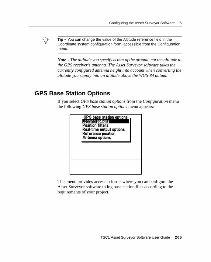
Configuring the Asset Surveyor Software 5
B Tip – You can change the value of the Altitude reference field in theCoordinate system configuration form, accessible from the Configurationmenu.
Note – The altitude you specify is that of the ground, not the altitude tothe GPS receiver’s antenna. The Asset Surveyor software takes thecurrently configured antenna height into account when converting thealtitude you supply into an altitude above the WGS-84 datum.
5.3 GPS Base Station OptionsIf you select GPS base station options from the Configuration menuthe following GPS base station options menu appears:
This menu provides access to forms where you can configure theAsset Surveyor software to log base station files according to therequirements of your project.
TSC1 Asset Surveyor Software User Guide 205
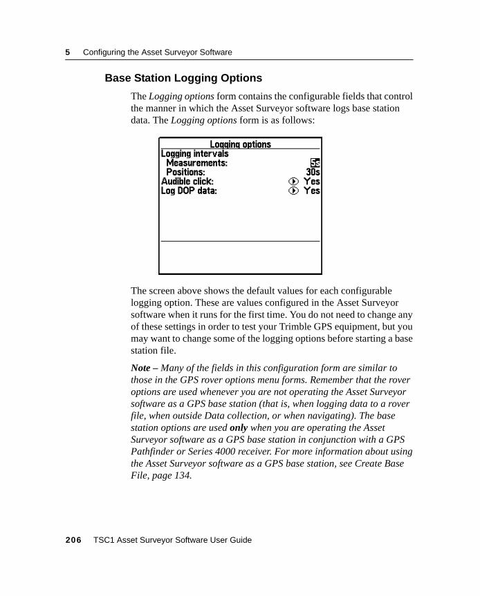
5 Configuring the Asset Surveyor Software
5.3.1 Base Station Logging Options
The Logging options form contains the configurable fields that controlthe manner in which the Asset Surveyor software logs base stationdata. The Logging options form is as follows:
The screen above shows the default values for each configurablelogging option. These are values configured in the Asset Surveyorsoftware when it runs for the first time. You do not need to change anyof these settings in order to test your Trimble GPS equipment, but youmay want to change some of the logging options before starting a basestation file.
Note – Many of the fields in this configuration form are similar tothose in the GPS rover options menu forms. Remember that the roveroptions are used whenever you are not operating the Asset Surveyorsoftware as a GPS base station (that is, when logging data to a roverfile, when outside Data collection, or when navigating). The basestation options are used only when you are operating the AssetSurveyor software as a GPS base station in conjunction with a GPSPathfinder or Series 4000 receiver. For more information about usingthe Asset Surveyor software as a GPS base station, see Create BaseFile, page 134.
206 TSC1 Asset Surveyor Software User Guide
Configuring the Asset Surveyor Software 5
Note – The Asset Surveyor software can be used to control a real-time(that is, RTCM-emitting or RTK-emitting) GPS base station, providedyour GPS receiver is a Series 4000, GPS Total Station 4800, or SiteSurveyor 4400 (for RTK and RTCM), or a Pro XL, Pro XR, orPro XRS (for RTCM only), and has the appropriate firmware optioninstalled. RTCM and RTK output is configured from the Real-timeoutput options entry in the GPS base station options menu. For moreinformation on operating the Asset Surveyor software in RTK mode,see the RTK for Mapping and GIS General Reference manual.
Note – The Asset Surveyor software does not support logging of aconventional base station file (for the purposes of post-processeddifferential correction) using a Series 4000, GPS Total Station 4800,or Site Surveyor 4400 receiver. The Series 4000, GPS Total Station4800, and Site Surveyor 4400 receivers can only be used for real-time(RTK/RTCM) operations. However, a base file containing time andephemeris information can still be logged.
Note – The Pro XR and Pro XRS (for RTCM), and the Series 4000,GPS Total Station 4800, and Site Surveyor 4400 (for RTCM/RTK)receivers can be operated as Unattended Real-Time Base Stations. Tooperate the Pro XR and Pro XRS receivers as Unattended Real-TimeBase Stations you must have the Unattended Real-Time Base Stationpower cable (P/N 32247).
B Tip – Trimble recommends that you always log sufficient data at yourbase station to permit differential correction by postprocessing, as radiolinks rarely provide 100% coverage of a data collection site. However, ifyou want to set up your Pro XR or Pro XRS receiver as a real-time basestation only, and want to leave it operating for a period of several days, setthe Measurements and Position logging intervals to ‘None’.
Because many of the fields of the GPS base station optionsconfiguration form are similar to those in the GPS rover options form,only the fields which differ significantly are described in this section.For details of fields not described below, see GPS Rover Options,page 165.
TSC1 Asset Surveyor Software User Guide 207
5 Configuring the Asset Surveyor Software
Measurements
The primary task of a GPS base station is to log raw GPSmeasurements from satellites for use when differentially correctingrover files. In order to provide accurate differential corrections, rawmeasurements should be logged reasonably often. The maximumpermitted measurement logging interval is 15 seconds. You can reducethe interval to a minimum of one second, but as this results in up to15 times as much data being logged by the Asset Surveyor software,you may find that your TSC1 datalogger’s storage is consumed veryquickly and that differential correction of rover files is slow. Thedefault setting of five seconds provides a good compromise betweenthe quality of postprocessed positions and the space and processingtime required.
B Tip – For the best accuracy, make sure that the position logging intervalfor each GPS rover is an exact multiple of the measurement logginginterval at the base station. If you set the position logging interval to avalue which is not an exact multiple of the base station’s measurementlogging interval, the Differential Correction utility has to computeinterpolated differential corrections. These are less accurate than thosecomputed when the logging intervals of the base station and rover(s) aresynchronized.
Note – If your GPS receiver is capable of supplying synchronizedcarrier phase measurements, the Asset Surveyor software requeststhese when operating as a base station. Otherwise, the Asset Surveyorsoftware logs (unsynchronized) raw pseudorange measurements. Onlyreceivers capable of supplying synchronized carrier phasemeasurements can be used as base stations for rovers operating incarrier phase mode.
208 TSC1 Asset Surveyor Software User Guide
Configuring the Asset Surveyor Software 5
Positions
The logging of GPS positions by a base station is not essential fordifferential correction. You can, however, choose to log a fewpositions in order to be able to graphically display the position of thebase station in the GPS Pathfinder Office software. If you set up atemporary base station on an unknown point, you may want to logpositions frequently to a base file. You can then differentially correctthat base file against another (perhaps more distant) base station inorder to discover the reference position for the temporary base station.Once this is known, you can use the local base file to correct localrover files.
Log DOP data
You can choose to log dilution of precision (DOP) values whenoperating as a base station, so that you have a record of the prevailingGPS conditions.
When the Log DOP data option is set to ‘Yes’, the Asset Surveyorsoftware logs values of PDOP, HDOP, VDOP and TDOP wheneverthe PDOP value varies by 0.1 or more, provided the PDOP is belowthe configured PDOP mask. This provides a good record of each DOPsituation that occurred throughout a data collection session. Thelogging of DOP information typically increases the size of a base fileby approximately 2–3%.
TSC1 Asset Surveyor Software User Guide 209
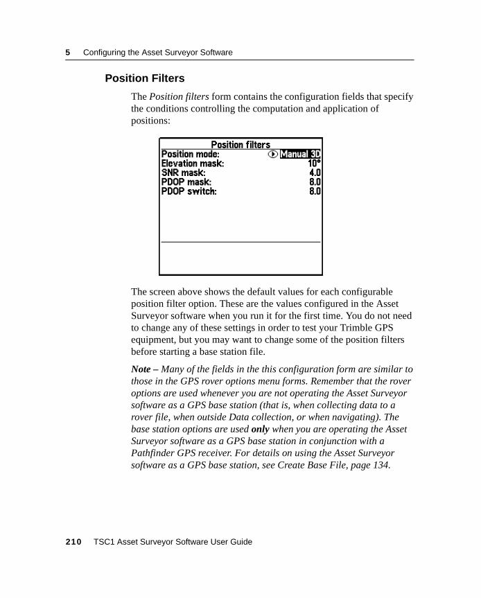
5 Configuring the Asset Surveyor Software
5.3.2 Position Filters
The Position filters form contains the configuration fields that specifythe conditions controlling the computation and application ofpositions:
The screen above shows the default values for each configurableposition filter option. These are the values configured in the AssetSurveyor software when you run it for the first time. You do not needto change any of these settings in order to test your Trimble GPSequipment, but you may want to change some of the position filtersbefore starting a base station file.
Note – Many of the fields in the this configuration form are similar tothose in the GPS rover options menu forms. Remember that the roveroptions are used whenever you are not operating the Asset Surveyorsoftware as a GPS base station (that is, when collecting data to arover file, when outside Data collection, or when navigating). Thebase station options are used only when you are operating the AssetSurveyor software as a GPS base station in conjunction with aPathfinder GPS receiver. For details on using the Asset Surveyorsoftware as a GPS base station, see Create Base File, page 134.
210 TSC1 Asset Surveyor Software User Guide
Configuring the Asset Surveyor Software 5
Position mode
You can operate a base station in any of the position modes which arepermitted for a rover, that is, ‘Manual 2D’, ‘Auto 2D/3D’, ‘Manual3D’ or ‘Overdet 3D’. In general, however, you can select a location fora base station such that it always tracks at least four satellites, so thatthere is no need to use any mode other than ‘Manual 3D’ (the default).
Elevation mask
The default elevation mask for a GPS base station is 10° (as opposedto the default of 15° for rovers).
C Warning – You must make sure that the elevation mask for the basestation is set sufficiently low that the base can always track any satellitesvisible to the rovers. As the rovers get further from the base station, thedifference between the elevation mask of the rovers and the basebecomes more critical (due to the curvature of the earth). As a rule, thedifference must be at least 1° for every 100 km between the base and therover.
SNR mask
The default signal-to-noise ratio mask for a GPS base station is four.The SNR mask does not influence the choice of satellites tracked bythe base station, but does determine when the base station can log GPSpositions. Note, however, that the logging of positions is not essentialfor differential correction.
Note – Trimble’s Site Surveyor 4400, GPS Total Station 4800, andSeries 4000 GPS receivers have a fixed internal SNR mask (of 4.0).The Asset Surveyor software’s SNR mask setting has no effect on theoperation of the Site Surveyor 4400, GPS Total Station 4800, andSeries 4000 receivers.
TSC1 Asset Surveyor Software User Guide 211
5 Configuring the Asset Surveyor Software
PDOP mask and PDOP switch
The default PDOP mask and PDOP switch for a GPS base station areboth 8.0, and are slightly higher than their equivalents for rovers. Thismakes sure that the base station is always able to log positionswhenever a rover is logging positions. Note, however, that the loggingof positions is not essential for differential correction.
5.3.3 Real-Time Output Options
When operating in base station mode, the Asset Surveyor software canlog GPS measurements for the differential correction of rover files.When connected to a Pro XR, Pro XRS, Pro XL, Series 4000, GPSTotal Station 4800, or Site Surveyor 4400 GPS receiver with theappropriate firmware option installed, the Asset Surveyor softwarecan be used to control a real-time base station, transmitting real-timedifferential corrections over a telemetry link.
Selecting Real-time output options from the GPS base station optionsmenu leads to a form where you can configure the real-time output tobe produced by your GPS receiver.
Note – The Real-time output options menu entry only appears whenyou are connected to a GPS receiver that supports real-time output.
Note – You cannot use the Series 4000, GPS Total Station 4800, andSite Surveyor 4400 receivers to log GPS measurements for thedifferential correction of rover files. Use them to operate a real-timeemitting base station only.
212 TSC1 Asset Surveyor Software User Guide
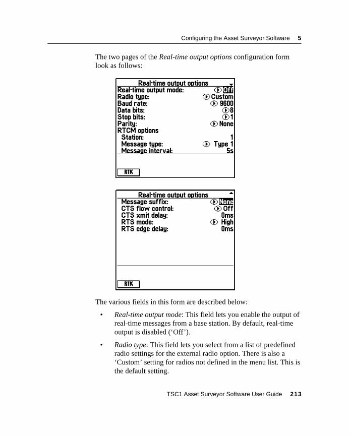
Configuring the Asset Surveyor Software 5
The two pages of the Real-time output options configuration formlook as follows:
The various fields in this form are described below:
• Real-time output mode: This field lets you enable the output ofreal-time messages from a base station. By default, real-timeoutput is disabled (‘Off’).
• Radio type: This field lets you select from a list of predefinedradio settings for the external radio option. There is also a‘Custom’ setting for radios not defined in the menu list. This isthe default setting.
TSC1 Asset Surveyor Software User Guide 213
5 Configuring the Asset Surveyor Software
• Baud rate, Data bits, Stop bits, Parity: These four fields let youspecify the serial parameters your telemetry link uses. Selectinga Trimble-defined radio in the Radio type field automaticallyupdates the following four communication fields for thatparticular radio. This is necessary for your GPS receiver toencode the RTCM data stream carried over the telemetry link.
The fields under the subheading RTCM options relate to the output ofRTCM only:
• Station: Every RTCM base station must specify an ID, which isa number in the range 0 to 1023. This ID number identifies theRTCM station and lets roving GPS receivers specify a particularbase station which they want to use. The default is 1.
• Message type: When RTCM output is enabled, your GPSreceiver emits a variety of RTCM messages. The mostimportant (and most frequent) of these contains satellitepseudo-range corrections as measured by the base stationreceiver. These corrections are used by roving receivers tocorrect the GPS positions they compute. The RTCM standardallows for two main types of pseudo-range corrections—‘Type 1’ and ‘Type 9’ messages. Each Type 1 message containspseudo-range corrections for all satellites currently tracked bythe base station. ‘Type 9’ messages split pseudorangecorrections for the set of tracked satellites over severalmessages. ‘Type 9’ messages are used by the U.S. Coast Guardbeacons, as they allow telemetry links with lower throughput.
• Message interval: The message interval determines the rate atwhich the selected RTCM message type (‘Type 1’ or ‘Type 9’)is emitted by your GPS base station. The default of five secondstends to provide a reasonable compromise between optimalaccuracy (which would be achieved with a one-second messageinterval) and the throughput of typical telemetry links.
• Message suffix: Each RTCM message can be followed by nosuffix (the default setting ‘None’), an ASCII carriage-returncharacter (‘CR’), an ASCII line-feed character (‘LF’), or acarriage-return/line-feed pair (‘CR/LF’).
214 TSC1 Asset Surveyor Software User Guide
Configuring the Asset Surveyor Software 5
• CTS flow control: Many telemetry links transmit data quiteslowly, and there is a need for flow control between the basestation GPS receiver and the radio. The Pro XR and Pro XRSreceivers implement hardware flow control using a CTS (ClearTo Send) line. By default, CTS flow control is ‘Off’, so thereceiver sends data regardless of the state of the CTS line.
• CTS xmit delay: This field lets you specify a delay, inmilliseconds, between when the radio raises the CTS line andthe GPS receiver continues to transmit RTCM data. If CTS flowcontrol is ‘Off’, the CTS xmit (transmit) delay is still used todelay transmission of data by the specified period. By default,this delay is ‘0 milliseconds’. The CTS xmit delay allows forradios which require a brief ‘warm up’ period before receivingdata for transmission.
• RTS mode: This field lets you specify the RTS mode, which canbe one of the following values: ‘Rx’ (for ‘receive’, meaning thatthe RTS (Ready to Send) signal is asserted by the receiver whenits receive buffer is nearly full and input must stop), ‘Tx’ (for‘transmit’, meaning that the RTS signal is asserted when thereceiver has data ready to output), ‘High’ (meaning that theRTS signal is always asserted by the receiver), and ‘Low’(meaning that the RTS signal is never asserted by the receiver).The default RTS mode is ‘High’.
• RTS edge delay: The RTS trailing edge field lets you specify adelay for the deactivation of the RTS signal after the last bit ofdata is sent. This can be useful in radio data transmissionsystems where RTS is used for the Push-to-talk signal.
C Warning – It is very important that you match your RTCM output serialparameters with the requirements of your transmitting and receivingradios. Any errors made when specifying serial parameters can cause theRTCM link to fail.
TSC1 Asset Surveyor Software User Guide 215
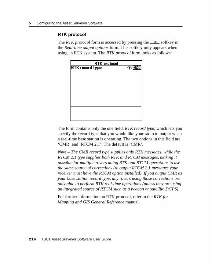
5 Configuring the Asset Surveyor Software
RTK protocol
The RTK protocol form is accessed by pressing theR softkey inthe Real-time output options form. This softkey only appears whenusing an RTK system. The RTK protocol form looks as follows:
The form contains only the one field, RTK record type, which lets youspecify the record type that you would like your radio to output whena real-time base station is operating. The two options in this field are‘CMR’ and ‘RTCM 2.1’. The default is ‘CMR’.
Note – The CMR record type supplies only RTK messages, while theRTCM 2.1 type supplies both RTK and RTCM messages, making itpossible for multiple rovers doing RTK and RTCM operations to usethe same source of corrections (to output RTCM 2.1 messages yourreceiver must have the RTCM option installed). If you output CMR asyour base station record type, any rovers using those corrections areonly able to perform RTK real-time operations (unless they are usingan integrated source of RTCM such as a beacon or satellite DGPS).
For further information on RTK protocol, refer to the RTK forMapping and GIS General Reference manual.
216 TSC1 Asset Surveyor Software User Guide
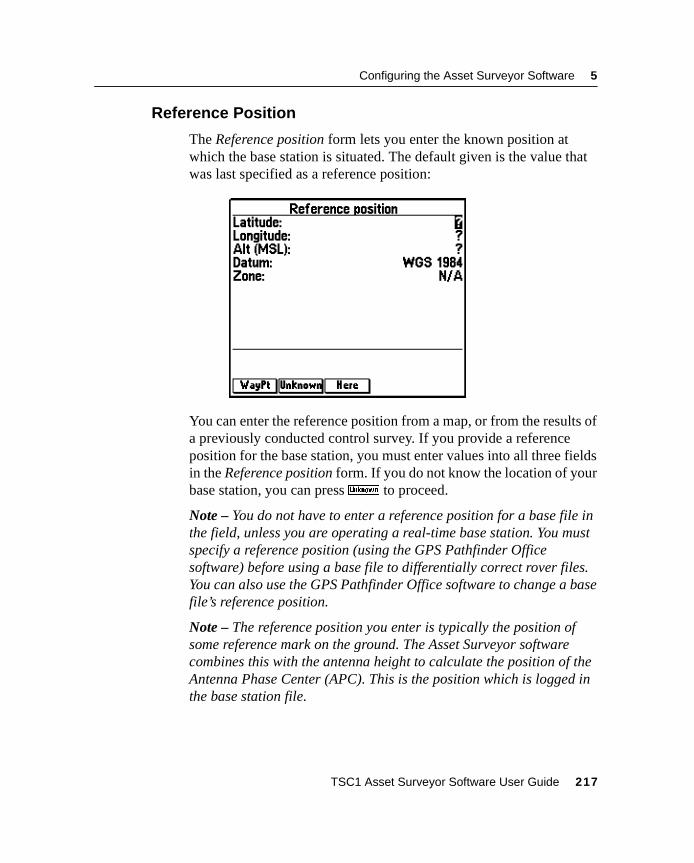
Configuring the Asset Surveyor Software 5
5.3.4 Reference Position
The Reference position form lets you enter the known position atwhich the base station is situated. The default given is the value thatwas last specified as a reference position:
You can enter the reference position from a map, or from the results ofa previously conducted control survey. If you provide a referenceposition for the base station, you must enter values into all three fieldsin the Reference position form. If you do not know the location of yourbase station, you can pressU to proceed.
Note – You do not have to enter a reference position for a base file inthe field, unless you are operating a real-time base station. You mustspecify a reference position (using the GPS Pathfinder Officesoftware) before using a base file to differentially correct rover files.You can also use the GPS Pathfinder Office software to change a basefile’s reference position.
Note – The reference position you enter is typically the position ofsome reference mark on the ground. The Asset Surveyor softwarecombines this with the antenna height to calculate the position of theAntenna Phase Center (APC). This is the position which is logged inthe base station file.
TSC1 Asset Surveyor Software User Guide 217
5 Configuring the Asset Surveyor Software
If you have previously recorded the location of the base station as awaypoint, you can pressw to open the menu of waypoints.Selecting a waypoint from this menu automatically fills in theReference position fields with the location of that waypoint.
B Tip – If you regularly operate a base station on more than one location,you can set up waypoints for each base location. This makes selection ofthe reference position very easy. You can also use the Asset Surveyorsoftware’s navigation abilities to assure yourself that you are specifyingthe correct waypoint as the reference position for a base station.
Pressh to fill in the reference position with the current GPSposition (if any).
C Warning – If you choose to append to an existing data file, you cannotspecify a new reference position. If you have moved to a different location,you must create a new base file. Consequently, if you reopen a base fileyou should make sure that you are at the exact location where the basefile was initially created. The reference position of the base station isstored when the base file is first created and positions subsequentlyappended to the file will be inaccurate if the receiver is not at the samereference position.
218 TSC1 Asset Surveyor Software User Guide
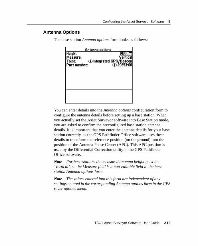
Configuring the Asset Surveyor Software 5
5.3.5 Antenna Options
The base station Antenna options form looks as follows:
You can enter details into the Antenna options configuration form toconfigure the antenna details before setting up a base station. Whenyou actually set the Asset Surveyor software into Base Station mode,you are asked to confirm the preconfigured base station antennadetails. It is important that you enter the antenna details for your basestation correctly, as the GPS Pathfinder Office software uses thesedetails to transform the reference position (on the ground) into theposition of the Antenna Phase Center (APC). This APC position isused by the Differential Correction utility in the GPS PathfinderOffice software.
Note – For base stations the measured antenna height must be‘Vertical’, so the Measure field is a non-editable field in the basestation Antenna options form.
Note – The values entered into this form are independent of anysettings entered in the corresponding Antenna options form in the GPSrover options menu.
TSC1 Asset Surveyor Software User Guide 219
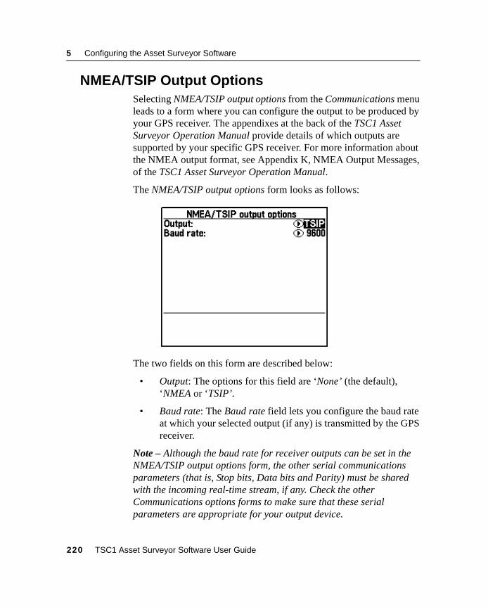
5 Configuring the Asset Surveyor Software
5.4 NMEA/TSIP Output OptionsSelecting NMEA/TSIP output options from the Communications menuleads to a form where you can configure the output to be produced byyour GPS receiver. The appendixes at the back of the TSC1 AssetSurveyor Operation Manual provide details of which outputs aresupported by your specific GPS receiver. For more information aboutthe NMEA output format, see Appendix K, NMEA Output Messages,of the TSC1 Asset Surveyor Operation Manual.
The NMEA/TSIP output options form looks as follows:
The two fields on this form are described below:
• Output: The options for this field are ‘None’ (the default),‘NMEA or ‘TSIP’.
• Baud rate: The Baud rate field lets you configure the baud rateat which your selected output (if any) is transmitted by the GPSreceiver.
Note – Although the baud rate for receiver outputs can be set in theNMEA/TSIP output options form, the other serial communicationsparameters (that is, Stop bits, Data bits and Parity) must be sharedwith the incoming real-time stream, if any. Check the otherCommunications options forms to make sure that these serialparameters are appropriate for your output device.
220 TSC1 Asset Surveyor Software User Guide
coordsys.bmp
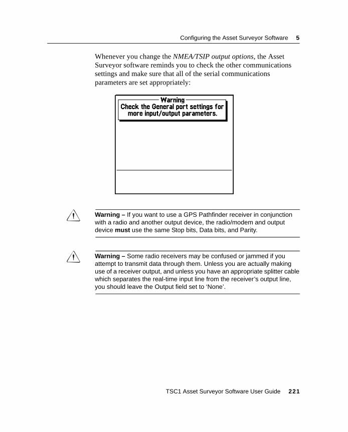
Configuring the Asset Surveyor Software 5
Whenever you change the NMEA/TSIP output options, the AssetSurveyor software reminds you to check the other communicationssettings and make sure that all of the serial communicationsparameters are set appropriately:
C Warning – If you want to use a GPS Pathfinder receiver in conjunctionwith a radio and another output device, the radio/modem and outputdevice must use the same Stop bits, Data bits, and Parity.
C Warning – Some radio receivers may be confused or jammed if youattempt to transmit data through them. Unless you are actually makinguse of a receiver output, and unless you have an appropriate splitter cablewhich separates the real-time input line from the receiver’s output line,you should leave the Output field set to ‘None’.
TSC1 Asset Surveyor Software User Guide 221
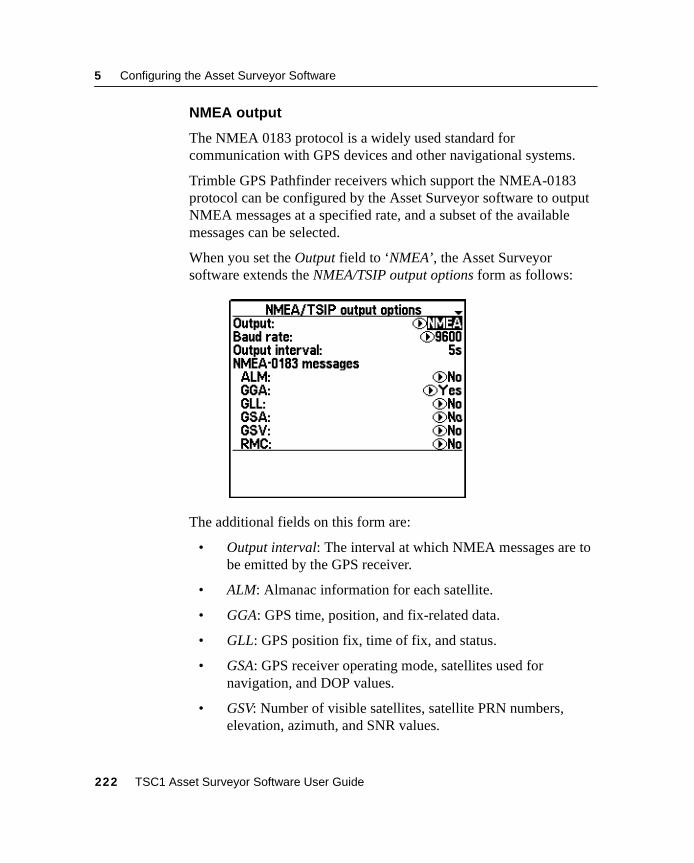
5 Configuring the Asset Surveyor Software
NMEA output
The NMEA 0183 protocol is a widely used standard forcommunication with GPS devices and other navigational systems.
Trimble GPS Pathfinder receivers which support the NMEA-0183protocol can be configured by the Asset Surveyor software to outputNMEA messages at a specified rate, and a subset of the availablemessages can be selected.
When you set the Output field to ‘NMEA’, the Asset Surveyorsoftware extends the NMEA/TSIP output options form as follows:
The additional fields on this form are:
• Output interval: The interval at which NMEA messages are tobe emitted by the GPS receiver.
• ALM: Almanac information for each satellite.
• GGA: GPS time, position, and fix-related data.
• GLL: GPS position fix, time of fix, and status.
• GSA: GPS receiver operating mode, satellites used fornavigation, and DOP values.
• GSV: Number of visible satellites, satellite PRN numbers,elevation, azimuth, and SNR values.
222 TSC1 Asset Surveyor Software User Guide
Configuring the Asset Surveyor Software 5
• RMC: Recommended minimum specific GPS/TRANSIT data.
• VTG: Actual track made good and speed over ground.
• ZDA: UTC day, month, year, and local time zone offset.
For a detailed description of each supported NMEA-0183 packet, seeAppendix K, NMEA Output Messages, in the TSC1 Asset SurveyorOperation Manual.
Once you save the contents of the NMEA/TSIP output options formwith the Output field set to ‘NMEA’, your Pathfinder GPS receiverbegins to emit the selected NMEA-0183 messages at the configuredOutput interval, provided the receiver supports NMEA output.
TSIP output
Trimble’s Standard Interface Protocol (TSIP) is a complex binaryprotocol for controlling GPS Pathfinder receivers. This is the protocolwhich the Asset Surveyor software uses to communicate with yourGPS Pathfinder receiver.
When you set the Output field to ‘TSIP’, your GPS Pathfinder Seriesreceiver starts to output TSIP messages to its auxiliary serial port. Youmay require a special cable to make use of this information. Youcannot control the frequency or nature of the TSIP messages that areoutput by the receiver, as these are determined by the Asset Surveyorsoftware.
Note – Certain GPS Pathfinder receivers, including the Pro XL, canemit an electronic pulse precisely on each GPS second (1 PPS). Thisforms a stream of pulses that can be used for precise synchronizationof external devices, and for correlation of external events with GPStimes and positions. For cabling details and pin configurations for thePro XL, refer to the Pro XL System Operation Manual. you do nothave to configure the Asset Surveyor software to obtain this 1 PPSoutput; the Pro XL emits it at all times.
TSC1 Asset Surveyor Software User Guide 223
5 Configuring the Asset Surveyor Software
5.5 Coordinate SystemTrimble’s GPS receivers provide you with your position anywhere onthe earth’s surface. GPS positions are normally expressed as latitudesand longitudes relative to a mathematical model called a datum. Thedatum used by GPS is called the World Geodetic System 1984 datum(or ‘WGS-84’). A datum is defined by the relationship between anellipsoid and an origin point. An ellipsoid is a three-dimensionalsurface shaped like a squashed sphere, which approximately modelsthe shape of the earth (either as a whole or over a part of the earth).The WGS-84 datum is defined in terms of the GRS80 ellipsoid.
For some applications (for example, marine navigation and aviation),GPS latitudes and longitudes can be used directly.
For most land-based GPS applications, and particularly for GIS datacollection applications, latitudes and longitudes are less convenient.Typically, a GIS represents the coordinates of geographic features in alocality of interest using a rectangular grid (running North and East)and presumes that the earth is locally flat. A local ellipsoid can bedefined to provide a good approximation to the shape of the earth inthat locality. A datum transformation and a map projection are thenused to transform coordinates from this local ellipsoid to the GIS’sflat-earth model.
Heights can be displayed by the Asset Surveyor software relative toeither a local ellipsoid, or an empirically defined surface known as thegeoid. This is a surface of constant gravitational equipotential whichapproximates mean sea level.
In summary, there are three models for describing geographiclocations:
• The flat North/East model of the GIS, possibly with heights aswell.
• The curved local ellipsoid, used by the GIS as a model of theearth’s surface locally.
• The curved GRS-80 ellipsoid, used by GPS as a model of theearth’s surface as a whole.
224 TSC1 Asset Surveyor Software User Guide
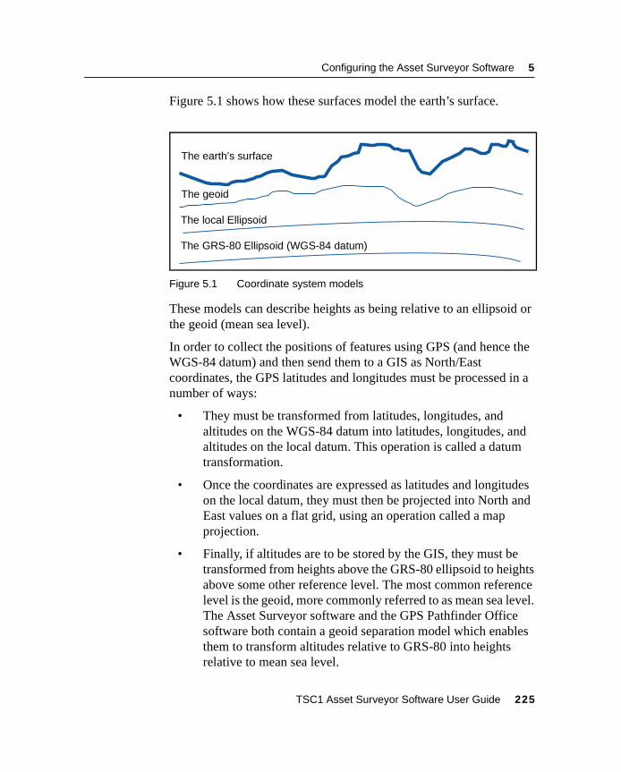
Configuring the Asset Surveyor Software 5
Figure 5.1 shows how these surfaces model the earth’s surface.
Figure 5.1 Coordinate system models
These models can describe heights as being relative to an ellipsoid orthe geoid (mean sea level).
In order to collect the positions of features using GPS (and hence theWGS-84 datum) and then send them to a GIS as North/Eastcoordinates, the GPS latitudes and longitudes must be processed in anumber of ways:
• They must be transformed from latitudes, longitudes, andaltitudes on the WGS-84 datum into latitudes, longitudes, andaltitudes on the local datum. This operation is called a datumtransformation.
• Once the coordinates are expressed as latitudes and longitudeson the local datum, they must then be projected into North andEast values on a flat grid, using an operation called a mapprojection.
• Finally, if altitudes are to be stored by the GIS, they must betransformed from heights above the GRS-80 ellipsoid to heightsabove some other reference level. The most common referencelevel is the geoid, more commonly referred to as mean sea level.The Asset Surveyor software and the GPS Pathfinder Officesoftware both contain a geoid separation model which enablesthem to transform altitudes relative to GRS-80 into heightsrelative to mean sea level.
The GRS-80 Ellipsoid (WGS-84 datum)
The local Ellipsoid
The earth’s surface
The geoid
TSC1 Asset Surveyor Software User Guide 225
5 Configuring the Asset Surveyor Software
Note – The geoid separation models used by the Asset Surveyorsoftware and the GPS Pathfinder Office software differ in accuracy.The Asset Surveyor software is necessarily approximate, while theGPS Pathfinder Office software is more accurate. If you requirealtitudes relative to a different reference level, or relative to a moreaccurate (perhaps local) mean sea level mode, you must process theheights in the GPS Pathfinder Office software before exporting themto your GIS. However, depending on space requirements, you cantransfer geoid models to the TSC1 datalogger to produce similarresults.
The Asset Surveyor software lets you specify a datum transformationand a map projection, so that you can see your GPS position (and theposition of features you may have recorded) in your local coordinatesystem. This makes it easy for you to check your position or navigateusing a map produced by your GIS.
Note – The Asset Surveyor software lets you specify that heights areshown relative to your local ellipsoid, or relative to mean sea level.
For your convenience, the Asset Surveyor software hides thecomplexities of datum transformations and map projections behind thecommon names for the coordinate systems with which you may befamiliar. Each named coordinate system has an associated datum(which encapsulates an ellipsoid) and a number of zones (each ofwhich is a named instance of a particular map projection).
You can create your own coordinate systems and sites using theCoordinate System Manager utility program in the GPS PathfinderOffice software. With the set of pre-defined coordinate systemssupplied by Trimble this should rarely be necessary.
226 TSC1 Asset Surveyor Software User Guide
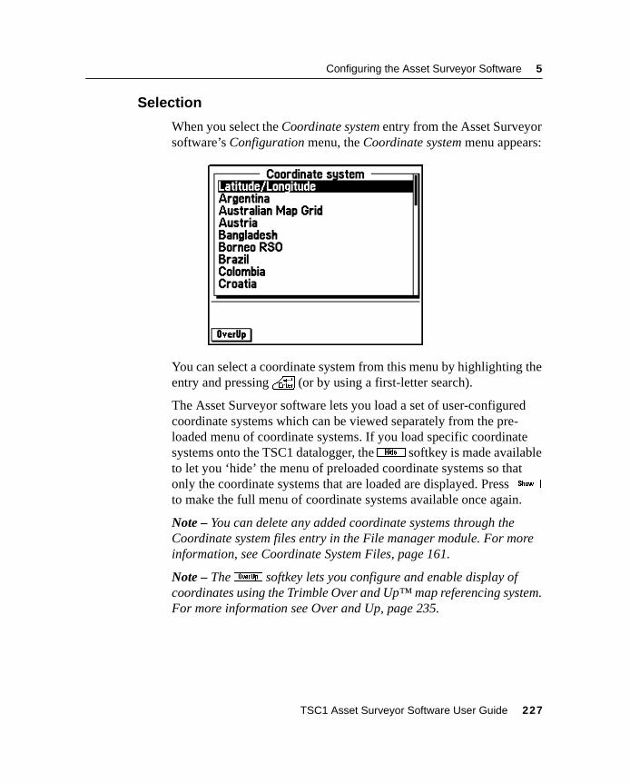
Configuring the Asset Surveyor Software 5
5.5.1 Selection
When you select the Coordinate system entry from the Asset Surveyorsoftware’s Configuration menu, the Coordinate system menu appears:
You can select a coordinate system from this menu by highlighting theentry and pressing\ (or by using a first-letter search).
The Asset Surveyor software lets you load a set of user-configuredcoordinate systems which can be viewed separately from the pre-loaded menu of coordinate systems. If you load specific coordinatesystems onto the TSC1 datalogger, thej softkey is made availableto let you ‘hide’ the menu of preloaded coordinate systems so thatonly the coordinate systems that are loaded are displayed. Presskto make the full menu of coordinate systems available once again.
Note – You can delete any added coordinate systems through theCoordinate system files entry in the File manager module. For moreinformation, see Coordinate System Files, page 161.
Note – Theo softkey lets you configure and enable display ofcoordinates using the Trimble Over and Up™ map referencing system.For more information see Over and Up, page 235.
TSC1 Asset Surveyor Software User Guide 227
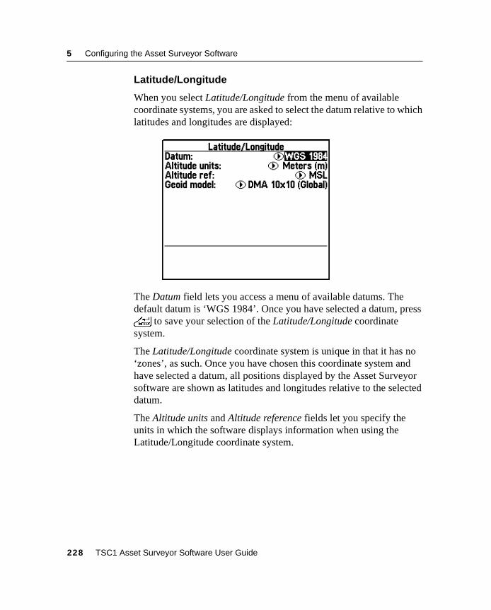
5 Configuring the Asset Surveyor Software
Latitude/Longitude
When you select Latitude/Longitude from the menu of availablecoordinate systems, you are asked to select the datum relative to whichlatitudes and longitudes are displayed:
The Datum field lets you access a menu of available datums. Thedefault datum is ‘WGS 1984’. Once you have selected a datum, press\ to save your selection of the Latitude/Longitude coordinatesystem.
The Latitude/Longitude coordinate system is unique in that it has no‘zones’, as such. Once you have chosen this coordinate system andhave selected a datum, all positions displayed by the Asset Surveyorsoftware are shown as latitudes and longitudes relative to the selecteddatum.
The Altitude units and Altitude reference fields let you specify theunits in which the software displays information when using theLatitude/Longitude coordinate system.
228 TSC1 Asset Surveyor Software User Guide
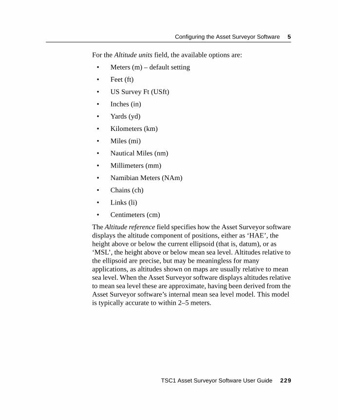
Configuring the Asset Surveyor Software 5
For the Altitude units field, the available options are:
• Meters (m) – default setting
• Feet (ft)
• US Survey Ft (USft)
• Inches (in)
• Yards (yd)
• Kilometers (km)
• Miles (mi)
• Nautical Miles (nm)
• Millimeters (mm)
• Namibian Meters (NAm)
• Chains (ch)
• Links (li)
• Centimeters (cm)
The Altitude reference field specifies how the Asset Surveyor softwaredisplays the altitude component of positions, either as ‘HAE’, theheight above or below the current ellipsoid (that is, datum), or as‘MSL’, the height above or below mean sea level. Altitudes relative tothe ellipsoid are precise, but may be meaningless for manyapplications, as altitudes shown on maps are usually relative to meansea level. When the Asset Surveyor software displays altitudes relativeto mean sea level these are approximate, having been derived from theAsset Surveyor software’s internal mean sea level model. This modelis typically accurate to within 2–5 meters.
TSC1 Asset Surveyor Software User Guide 229
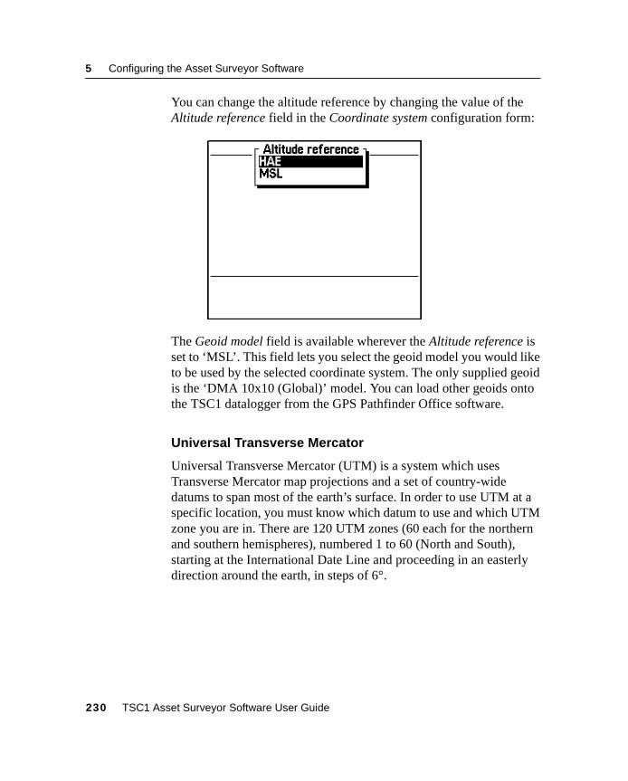
5 Configuring the Asset Surveyor Software
You can change the altitude reference by changing the value of theAltitude reference field in the Coordinate system configuration form:
The Geoid model field is available wherever the Altitude reference isset to ‘MSL’. This field lets you select the geoid model you would liketo be used by the selected coordinate system. The only supplied geoidis the ‘DMA 10x10 (Global)’ model. You can load other geoids ontothe TSC1 datalogger from the GPS Pathfinder Office software.
Universal Transverse Mercator
Universal Transverse Mercator (UTM) is a system which usesTransverse Mercator map projections and a set of country-widedatums to span most of the earth’s surface. In order to use UTM at aspecific location, you must know which datum to use and which UTMzone you are in. There are 120 UTM zones (60 each for the northernand southern hemispheres), numbered 1 to 60 (North and South),starting at the International Date Line and proceeding in an easterlydirection around the earth, in steps of 6°.
230 TSC1 Asset Surveyor Software User Guide
Configuring the Asset Surveyor Software 5
When you select Universal Transverse Mercator from the menu ofavailable coordinate systems, the Asset Surveyor software displays aform where you can specify the zone, datum, altitude and coordinateunits, altitude reference, and geoid model:
The Zone field requires you to select a zone from the options availablein the pop-up menu. Then select a datum from the menu in the Datumfield.
C Warning – It is very important that you specify the correct datum whenusing UTM. Traditionally, the NAD-27 datum has been used for UTMthroughout the United States, but recently the NAD-83 datum has beenused as the U.S. base for UTM in some applications. If you want the AssetSurveyor software to display GPS positions which are compatible withUTM maps produced by your GIS, you must make sure that the UTMzone, datum and scale factor used by the GIS are all entered into theAsset Surveyor software correctly.
Once you have entered the Zone and Datum, press\ to save yourselections. Once you have chosen the UTM coordinate system andaccepted a zone, all positions displayed by the Asset Surveyorsoftware are shown in UTM coordinates.
The Altitude units, Coordinate units, and Altitude reference fields letyou specify the units in which the software displays information whenusing the UTM coordinate system.
TSC1 Asset Surveyor Software User Guide 231
5 Configuring the Asset Surveyor Software
For the Altitude units and Coordinate units fields, the options are:
• Meters (m) - default setting
• Feet (ft)
• US Survey Ft (USft)
• Inches (in)
• Yards (yd)
• Kilometers (km)
• Miles (mi)
• Nautical Miles (nm)
• Millimeters (mm)
• Namibian Meters (NAm)
• Chains (ch)
• Links (li)
• Centimeters (cm)
For a detailed description of the Altitude reference field, seeLatitude/Longitude, page 228.
The Geoid model field is available wherever the Altitude reference isset to ‘MSL’. This field lets you select the geoid model you would liketo be used by the selected coordinate system. The only supplied geoidis the ‘DMA 10x10 (Global)’ model. You can transfer other geoids tothe TSC1 datalogger from the GPS Pathfinder Office software.
Other
Apart from the special Latitude/Longitude and Universal TransverseMercator coordinate systems, the Asset Surveyor software comes witha selection of predefined coordinate systems. You can also edit thesepredefined coordinate systems, or create new ones using theCoordinate System Manager utility in the GPS Pathfinder Officesoftware.
232 TSC1 Asset Surveyor Software User Guide
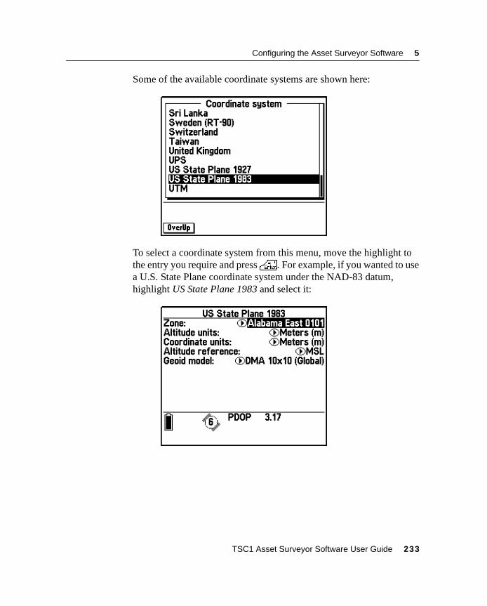
Configuring the Asset Surveyor Software 5
Some of the available coordinate systems are shown here:
To select a coordinate system from this menu, move the highlight tothe entry you require and press\. For example, if you wanted to usea U.S. State Plane coordinate system under the NAD-83 datum,highlight US State Plane 1983 and select it:
TSC1 Asset Surveyor Software User Guide 233
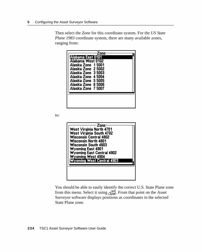
5 Configuring the Asset Surveyor Software
Then select the Zone for this coordinate system. For the US StatePlane 1983 coordinate system, there are many available zones,ranging from:
to:
You should be able to easily identify the correct U.S. State Plane zonefrom this menu. Select it using\ . From that point on the AssetSurveyor software displays positions as coordinates in the selectedState Plane zone.
234 TSC1 Asset Surveyor Software User Guide
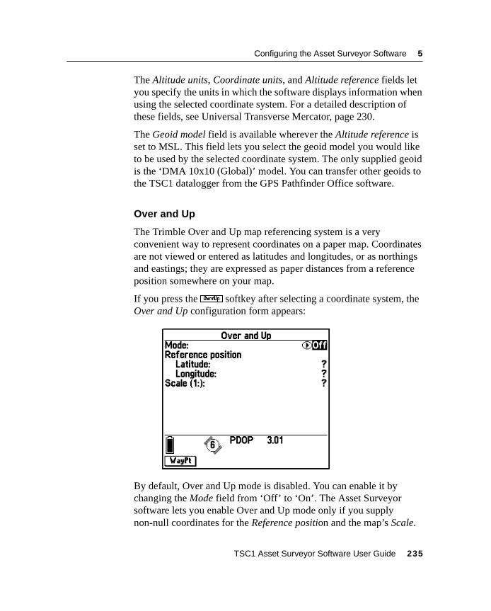
Configuring the Asset Surveyor Software 5
The Altitude units, Coordinate units, and Altitude reference fields letyou specify the units in which the software displays information whenusing the selected coordinate system. For a detailed description ofthese fields, see Universal Transverse Mercator, page 230.
The Geoid model field is available wherever the Altitude reference isset to MSL. This field lets you select the geoid model you would liketo be used by the selected coordinate system. The only supplied geoidis the ‘DMA 10x10 (Global)’ model. You can transfer other geoids tothe TSC1 datalogger from the GPS Pathfinder Office software.
Over and Up
The Trimble Over and Up map referencing system is a veryconvenient way to represent coordinates on a paper map. Coordinatesare not viewed or entered as latitudes and longitudes, or as northingsand eastings; they are expressed as paper distances from a referenceposition somewhere on your map.
If you press theo softkey after selecting a coordinate system, theOver and Up configuration form appears:
By default, Over and Up mode is disabled. You can enable it bychanging the Mode field from ‘Off’ to ‘On’. The Asset Surveyorsoftware lets you enable Over and Up mode only if you supplynon-null coordinates for the Reference position and the map’s Scale.
TSC1 Asset Surveyor Software User Guide 235
5 Configuring the Asset Surveyor Software
Note – The Reference position waypoint coordinates must be enteredin terms of the currently selected coordinate system. Thew softkeycan be used to select a pre-entered waypoint as the reference positionfor your map.
Once you have entered appropriate values, press\ to save the Overand Up settings.
When you subsequently view positions (for example, the current GPSposition, the position of a collected feature, or that of a waypoint), theAsset Surveyor software shows these positions relative to the Overand Up reference position, in paper units. The position is shown asLeft or Right of the reference position, and either Up or Down fromthe reference position. If your configured distance units are metric, theOver and Up distances are shown in centimeters (cm); otherwise theyare shown in inches (in).
Note – Over and Up mode only works with maps which are aligned toTrue north.
C Warning – Remember to change your Over and Up settings wheneveryou change maps.
5.5.2 Site Selection
The Asset Surveyor software also lets you select a local site to be usedas the configured coordinate system. A local site is an adjustment tothe zone of a coordinate system, consisting of a translation, scaling,rotation about an origin, and an optional height adjustment. It isapplied in order to calibrate GPS positions against existing surveymarks to derive a vertical and horizontal plane adjustment. For furtherexplanation of local site creation, see the Coordinate System Managerdocumentation.
236 TSC1 Asset Surveyor Software User Guide
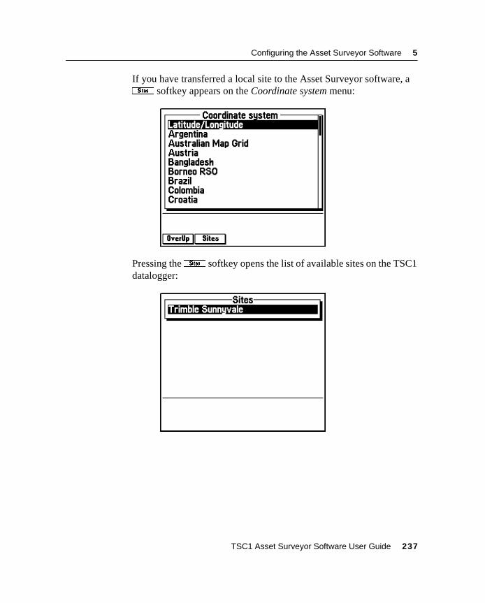
Configuring the Asset Surveyor Software 5
If you have transferred a local site to the Asset Surveyor software, av softkey appears on the Coordinate system menu:
Pressing thev softkey opens the list of available sites on the TSC1datalogger:
TSC1 Asset Surveyor Software User Guide 237
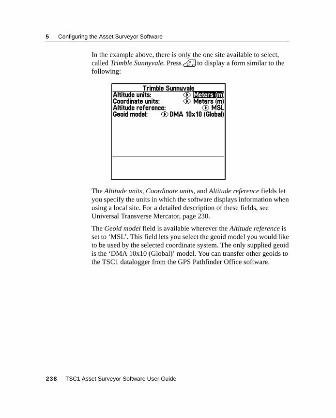
5 Configuring the Asset Surveyor Software
In the example above, there is only the one site available to select,called Trimble Sunnyvale. Press\ to display a form similar to thefollowing:
The Altitude units, Coordinate units, and Altitude reference fields letyou specify the units in which the software displays information whenusing a local site. For a detailed description of these fields, seeUniversal Transverse Mercator, page 230.
The Geoid model field is available wherever the Altitude reference isset to ‘MSL’. This field lets you select the geoid model you would liketo be used by the selected coordinate system. The only supplied geoidis the ‘DMA 10x10 (Global)’ model. You can transfer other geoids tothe TSC1 datalogger from the GPS Pathfinder Office software.
238 TSC1 Asset Surveyor Software User Guide
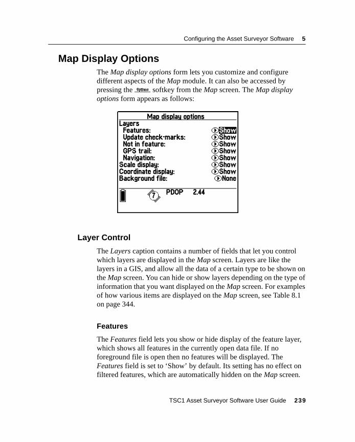
Configuring the Asset Surveyor Software 5
5.6 Map Display OptionsThe Map display options form lets you customize and configuredifferent aspects of the Map module. It can also be accessed bypressing the& softkey from the Map screen. The Map displayoptions form appears as follows:
5.6.1 Layer Control
The Layers caption contains a number of fields that let you controlwhich layers are displayed in the Map screen. Layers are like thelayers in a GIS, and allow all the data of a certain type to be shown onthe Map screen. You can hide or show layers depending on the type ofinformation that you want displayed on the Map screen. For examplesof how various items are displayed on the Map screen, see Table 8.1on page 344.
Features
The Features field lets you show or hide display of the feature layer,which shows all features in the currently open data file. If noforeground file is open then no features will be displayed. TheFeatures field is set to ‘Show’ by default. Its setting has no effect onfiltered features, which are automatically hidden on the Map screen.
TSC1 Asset Surveyor Software User Guide 239
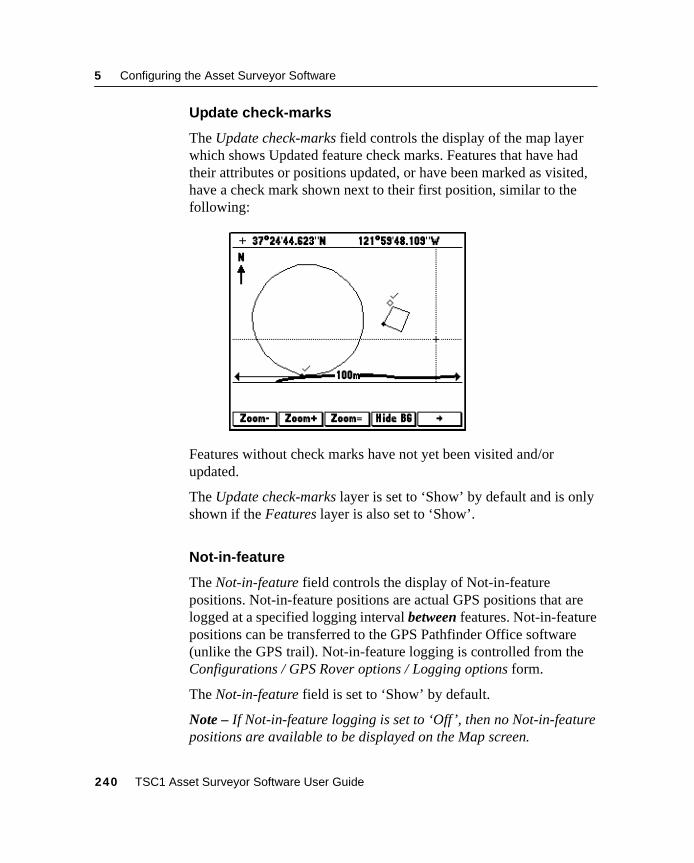
5 Configuring the Asset Surveyor Software
Update check-marks
The Update check-marks field controls the display of the map layerwhich shows Updated feature check marks. Features that have hadtheir attributes or positions updated, or have been marked as visited,have a check mark shown next to their first position, similar to thefollowing:
Features without check marks have not yet been visited and/orupdated.
The Update check-marks layer is set to ‘Show’ by default and is onlyshown if the Features layer is also set to ‘Show’.
Not-in-feature
The Not-in-feature field controls the display of Not-in-featurepositions. Not-in-feature positions are actual GPS positions that arelogged at a specified logging interval between features. Not-in-featurepositions can be transferred to the GPS Pathfinder Office software(unlike the GPS trail). Not-in-feature logging is controlled from theConfigurations / GPS Rover options / Logging options form.
The Not-in-feature field is set to ‘Show’ by default.
Note – If Not-in-feature logging is set to ‘Off’, then no Not-in-featurepositions are available to be displayed on the Map screen.
240 TSC1 Asset Surveyor Software User Guide
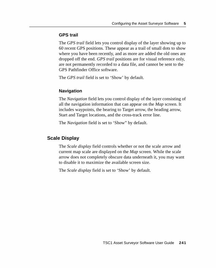
Configuring the Asset Surveyor Software 5
GPS trail
The GPS trail field lets you control display of the layer showing up to60 recent GPS positions. These appear as a trail of small dots to showwhere you have been recently, and as more are added the old ones aredropped off the end. GPS trail positions are for visual reference only,are not permanently recorded to a data file, and cannot be sent to theGPS Pathfinder Office software.
The GPS trail field is set to ‘Show’ by default.
Navigation
The Navigation field lets you control display of the layer consisting ofall the navigation information that can appear on the Map screen. Itincludes waypoints, the bearing to Target arrow, the heading arrow,Start and Target locations, and the cross-track error line.
The Navigation field is set to ‘Show” by default.
5.6.2 Scale Display
The Scale display field controls whether or not the scale arrow andcurrent map scale are displayed on the Map screen. While the scalearrow does not completely obscure data underneath it, you may wantto disable it to maximize the available screen size.
The Scale display field is set to ‘Show’ by default.
TSC1 Asset Surveyor Software User Guide 241
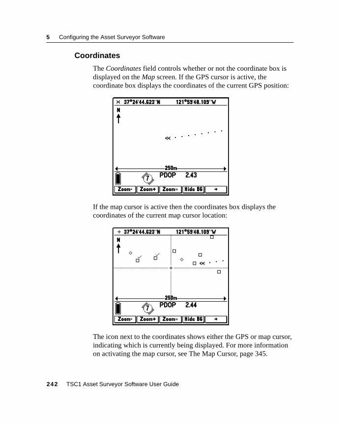
5 Configuring the Asset Surveyor Software
5.6.3 Coordinates
The Coordinates field controls whether or not the coordinate box isdisplayed on the Map screen. If the GPS cursor is active, thecoordinate box displays the coordinates of the current GPS position:
If the map cursor is active then the coordinates box displays thecoordinates of the current map cursor location:
The icon next to the coordinates shows either the GPS or map cursor,indicating which is currently being displayed. For more informationon activating the map cursor, see The Map Cursor, page 345.
242 TSC1 Asset Surveyor Software User Guide
Configuring the Asset Surveyor Software 5
The Coordinates option is set to ‘Show’ by default.
Note – To change to a different coordinate system, select theCoordinate Systems entry on the Configuration menu. To change thecoordinate order, select Units and display.
5.6.4 Background File
The Background file field lets you select a data file to be displayed onthe Map screen as a read-only background file. The background file isfor visual reference only and features in it cannot be selected orqueried. The Background file field is set to ‘None’ by default. Selectthe data file you want to open from the list, which shows all rover andbackground files on the system. Base files cannot be opened asbackground files.
Use the1 and2 softkeys on the Map screen to show or hidethe specified background file. For more information, see BackgroundFile, page 243.
Note – You cannot use the same file as the background and theforeground data file.
5.6.5 Symbols
The Asset Surveyor software lets you customize the symbolsdisplayed for point features on the Map screen and in the Review datalist. This makes it easier to distinguish between particular types ofpoint features.
PressF to open the Point feature symbols menu, where you cancustomize the symbols used for the display of point feature types onthe Map screen. TheF softkey can also be accessed from the Datadictionary menu in the File manager module, or the Map displayoptions form in the Map module.
TSC1 Asset Surveyor Software User Guide 243
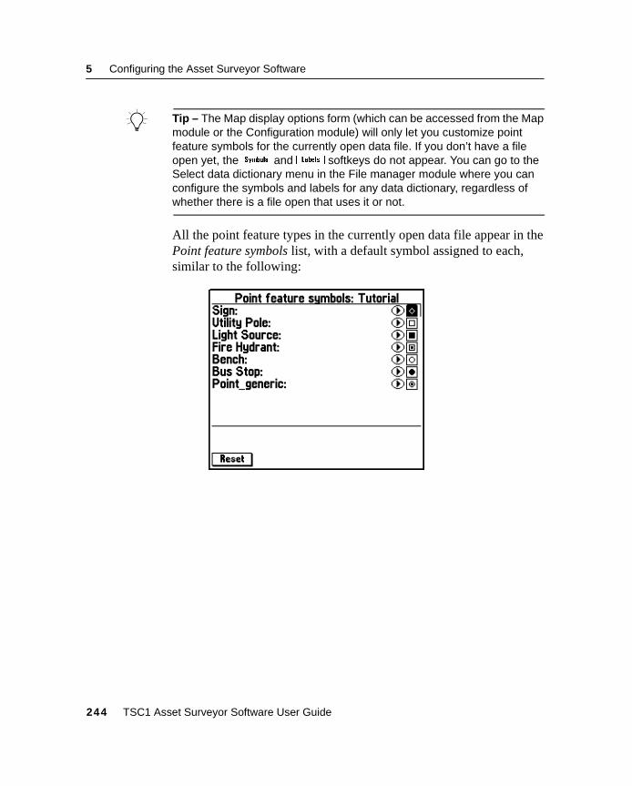
5 Configuring the Asset Surveyor Software
B Tip – The Map display options form (which can be accessed from the Mapmodule or the Configuration module) will only let you customize pointfeature symbols for the currently open data file. If you don’t have a fileopen yet, theF and\ softkeys do not appear. You can go to theSelect data dictionary menu in the File manager module where you canconfigure the symbols and labels for any data dictionary, regardless ofwhether there is a file open that uses it or not.
All the point feature types in the currently open data file appear in thePoint feature symbols list, with a default symbol assigned to each,similar to the following:
244 TSC1 Asset Surveyor Software User Guide
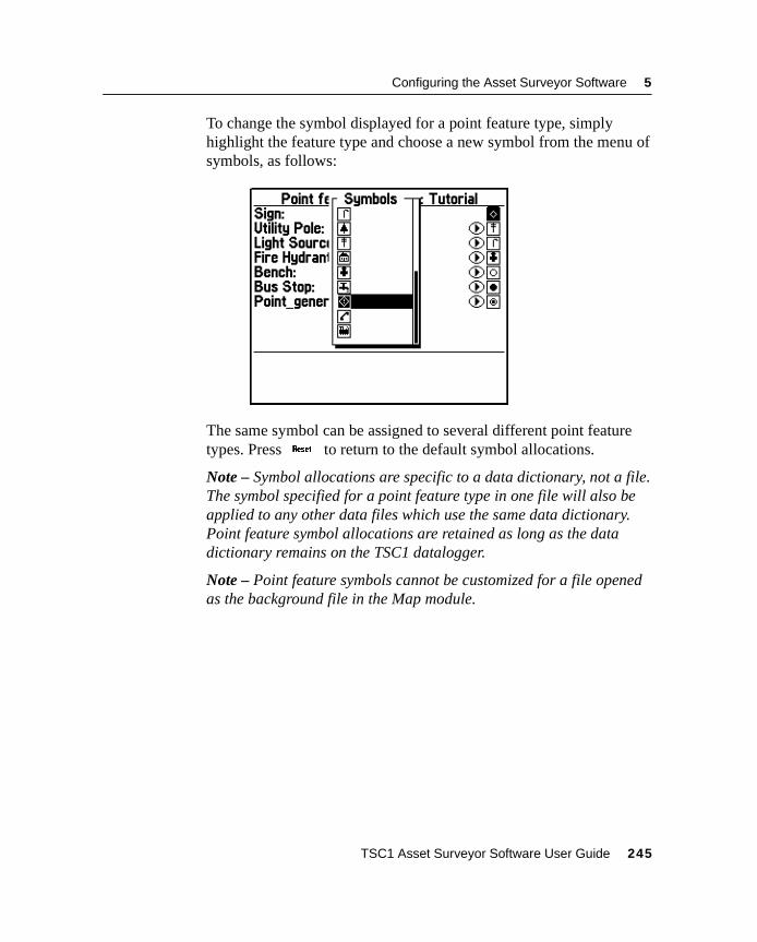
Configuring the Asset Surveyor Software 5
To change the symbol displayed for a point feature type, simplyhighlight the feature type and choose a new symbol from the menu ofsymbols, as follows:
The same symbol can be assigned to several different point featuretypes. PressK to return to the default symbol allocations.
Note – Symbol allocations are specific to a data dictionary, not a file.The symbol specified for a point feature type in one file will also beapplied to any other data files which use the same data dictionary.Point feature symbol allocations are retained as long as the datadictionary remains on the TSC1 datalogger.
Note – Point feature symbols cannot be customized for a file openedas the background file in the Map module.
TSC1 Asset Surveyor Software User Guide 245
5 Configuring the Asset Surveyor Software
5.6.6 Labels
The Asset Surveyor software lets you specify two attribute values tobe displayed for the selected feature on the Map screen and in theReview data list. These two labels make it easier to distinguishbetween features.
When you create a feature in the Data Dictionary Editor utility in theGPS Pathfinder Office software, the first two attributes in the featureare selected by default as the labels. You can change the selectedlabels in the Data Dictionary Editor utility, or in the Asset Surveyorsoftware. Any changes you make to label assignments in the AssetSurveyor software remain in effect until you remove the datadictionary from the TSC1 datalogger.
In the Map display options form, press\ to open the Select featureto label list. The\ softkey can also be accessed from the Selectdata dictionary menu in the File manager module, or the Map displayoptions form in the Map module.
B Tip – The Map display options form (which can be accessed from the Mapmodule or the Configuration module) will only let you customize labels forthe currently open data file. If you do not have a file open yet, theFand\ softkeys do not appear. You can go to the Select data dictionarymenu in the File manager module where you can configure the symbolsand labels for any data dictionary, regardless of whether there is a fileopen that uses it or not.
246 TSC1 Asset Surveyor Software User Guide
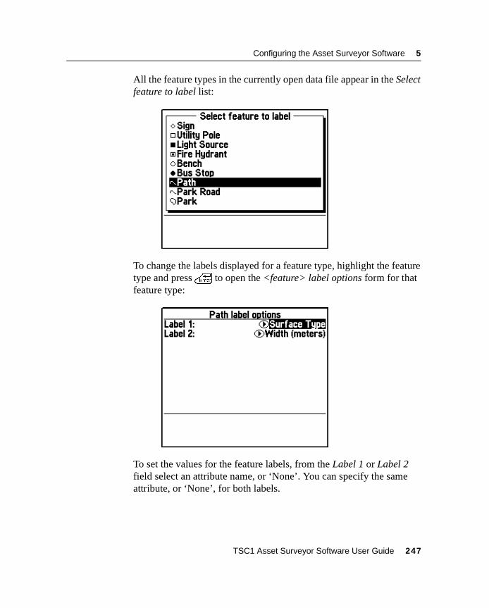
Configuring the Asset Surveyor Software 5
All the feature types in the currently open data file appear in the Selectfeature to label list:
To change the labels displayed for a feature type, highlight the featuretype and press\ to open the <feature> label options form for thatfeature type:
To set the values for the feature labels, from the Label 1 or Label 2field select an attribute name, or ‘None’. You can specify the sameattribute, or ‘None’, for both labels.
TSC1 Asset Surveyor Software User Guide 247
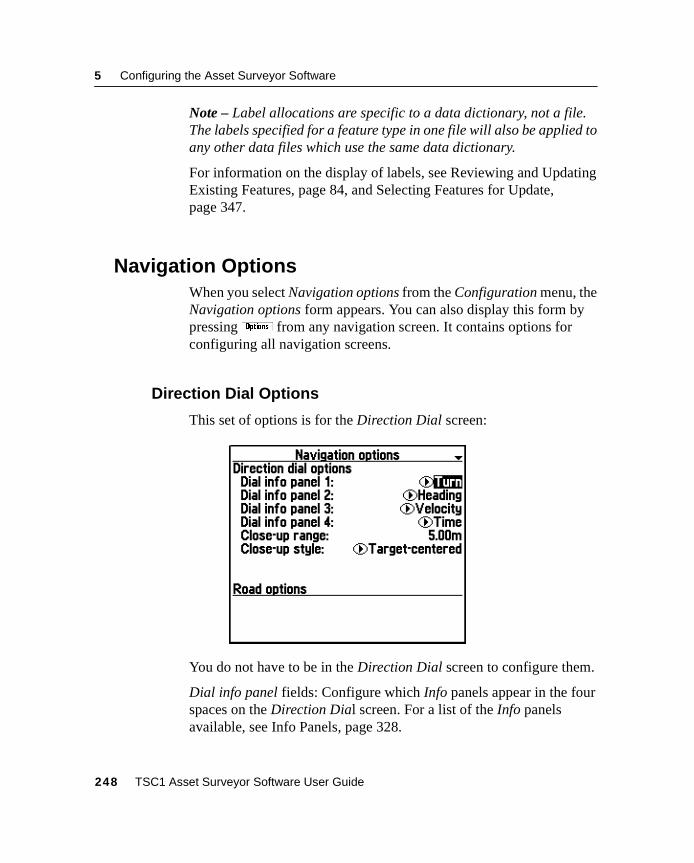
5 Configuring the Asset Surveyor Software
Note – Label allocations are specific to a data dictionary, not a file.The labels specified for a feature type in one file will also be applied toany other data files which use the same data dictionary.
For information on the display of labels, see Reviewing and UpdatingExisting Features, page 84, and Selecting Features for Update,page 347.
5.7 Navigation OptionsWhen you select Navigation options from the Configuration menu, theNavigation options form appears. You can also display this form bypressing& from any navigation screen. It contains options forconfiguring all navigation screens.
5.7.1 Direction Dial Options
This set of options is for the Direction Dial screen:
You do not have to be in the Direction Dial screen to configure them.
Dial info panel fields: Configure which Info panels appear in the fourspaces on the Direction Dial screen. For a list of the Info panelsavailable, see Info Panels, page 328.
248 TSC1 Asset Surveyor Software User Guide
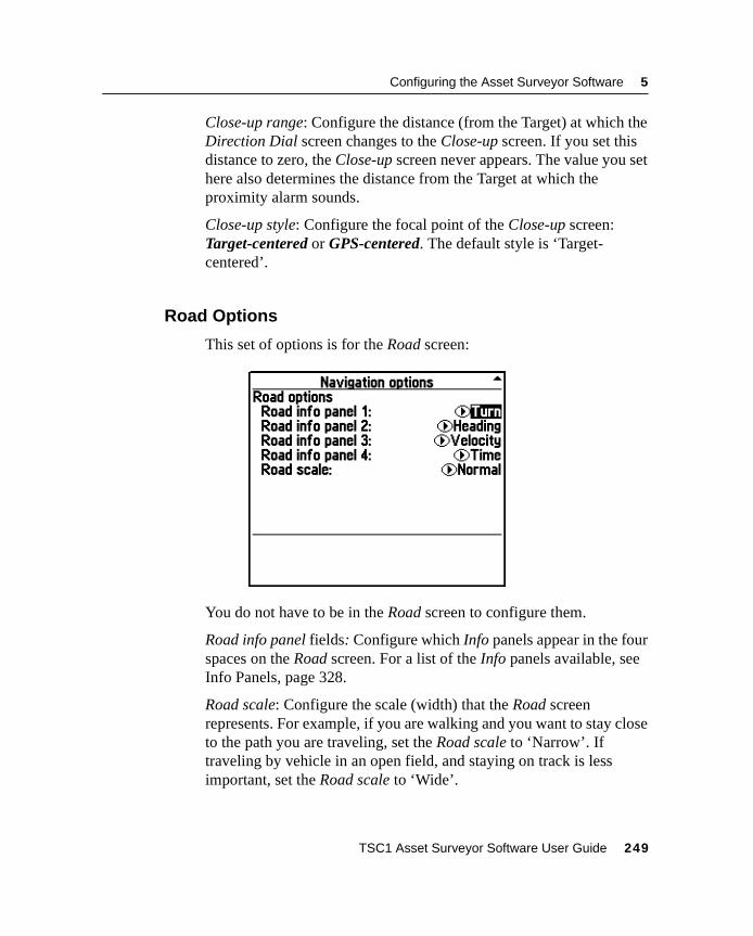
Configuring the Asset Surveyor Software 5
Close-up range: Configure the distance (from the Target) at which theDirection Dial screen changes to the Close-up screen. If you set thisdistance to zero, the Close-up screen never appears. The value you sethere also determines the distance from the Target at which theproximity alarm sounds.
Close-up style: Configure the focal point of the Close-up screen:Target-centered or GPS-centered. The default style is ‘Target-centered’.
5.7.2 Road Options
This set of options is for the Road screen:
You do not have to be in the Road screen to configure them.
Road info panel fields: Configure which Info panels appear in the fourspaces on the Road screen. For a list of the Info panels available, seeInfo Panels, page 328.
Road scale: Configure the scale (width) that the Road screenrepresents. For example, if you are walking and you want to stay closeto the path you are traveling, set the Road scale to ‘Narrow’. Iftraveling by vehicle in an open field, and staying on track is lessimportant, set the Road scale to ‘Wide’.
TSC1 Asset Surveyor Software User Guide 249
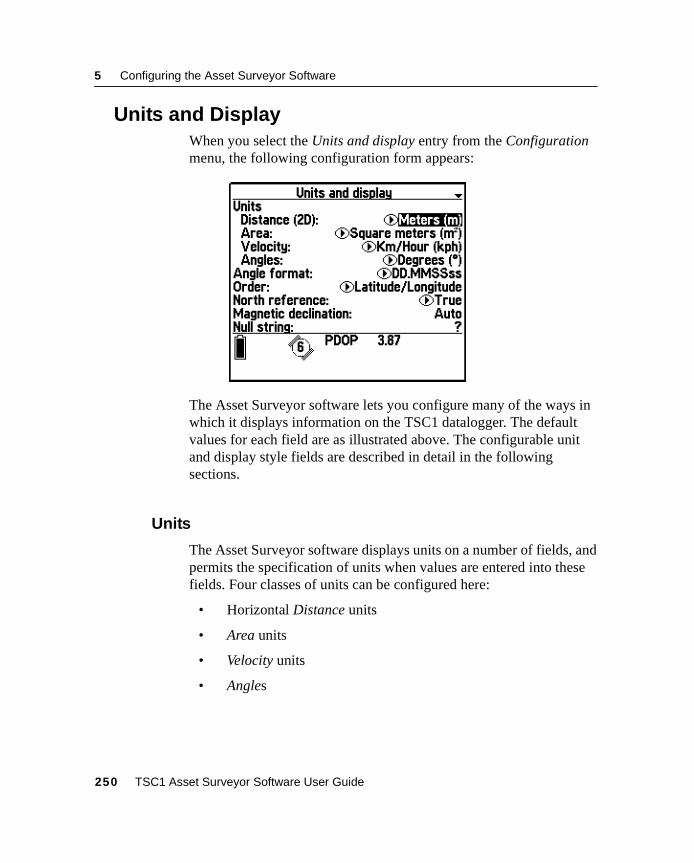
5 Configuring the Asset Surveyor Software
5.8 Units and DisplayWhen you select the Units and display entry from the Configurationmenu, the following configuration form appears:
The Asset Surveyor software lets you configure many of the ways inwhich it displays information on the TSC1 datalogger. The defaultvalues for each field are as illustrated above. The configurable unitand display style fields are described in detail in the followingsections.
5.8.1 Units
The Asset Surveyor software displays units on a number of fields, andpermits the specification of units when values are entered into thesefields. Four classes of units can be configured here:
• Horizontal Distance units
• Area units
• Velocity units
• Angles
250 TSC1 Asset Surveyor Software User Guide
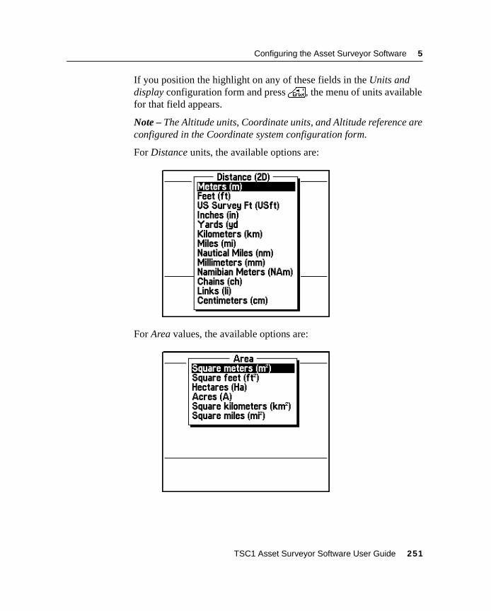
Configuring the Asset Surveyor Software 5
If you position the highlight on any of these fields in the Units anddisplay configuration form and press\, the menu of units availablefor that field appears.
Note – The Altitude units, Coordinate units, and Altitude reference areconfigured in the Coordinate system configuration form.
For Distance units, the available options are:
For Area values, the available options are:
TSC1 Asset Surveyor Software User Guide 251
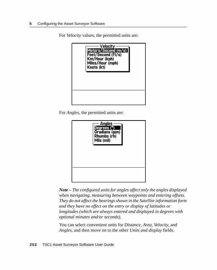
5 Configuring the Asset Surveyor Software
For Velocity values, the permitted units are:
For Angles, the permitted units are:
Note – The configured units for angles affect only the angles displayedwhen navigating, measuring between waypoints and entering offsets.They do not affect the bearings shown in the Satellite information formand they have no effect on the entry or display of latitudes orlongitudes (which are always entered and displayed in degrees withoptional minutes and/or seconds).
You can select convenient units for Distance, Area, Velocity, andAngles, and then move on to the other Units and display fields.
252 TSC1 Asset Surveyor Software User Guide

Configuring the Asset Surveyor Software 5
5.8.2 Angle Format
You can configure the format for the entry of angles which use degrees(including latitudes and longitudes) into the Asset Surveyor softwarefields. The available formats are:
All full angles are displayed in the ‘DD°MM'SS.ss’ format. Angles canalso be entered in this format by typing each punctuation character, byselecting them from thei menu, or by separating each of thecomponents of the angle by a space.
The default ‘DD.MMSSss’ format lets you enter a full angle indegrees, minutes, and seconds with the minimum of punctuation.
The ‘DD MM.mmm’ format lets you enter an angle as degrees anddecimal minutes, with a space character as punctuation to separate thetwo components. The ‘DD.ddd’ format lets you enter an angle indecimal degrees.
B Tip – When entering latitudes and longitudes, remember that these aresigned values, with the sign being used to indicate the hemisphere (Northor South for latitudes, East or West for longitudes). You can enter the signas ‘+’, ‘–’, ‘N’, ‘S’, ‘E’ or ‘W’, at either the start or end of the field. If you donot specify a sign then the Asset Surveyor software defaults to thehemisphere in which you are currently operating, as determined by yourmost recent GPS position.
TSC1 Asset Surveyor Software User Guide 253
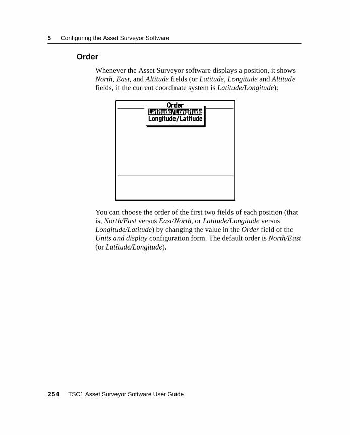
5 Configuring the Asset Surveyor Software
5.8.3 Order
Whenever the Asset Surveyor software displays a position, it showsNorth, East, and Altitude fields (or Latitude, Longitude and Altitudefields, if the current coordinate system is Latitude/Longitude):
You can choose the order of the first two fields of each position (thatis, North/East versus East/North, or Latitude/Longitude versusLongitude/Latitude) by changing the value in the Order field of theUnits and display configuration form. The default order is North/East(or Latitude/Longitude).
254 TSC1 Asset Surveyor Software User Guide
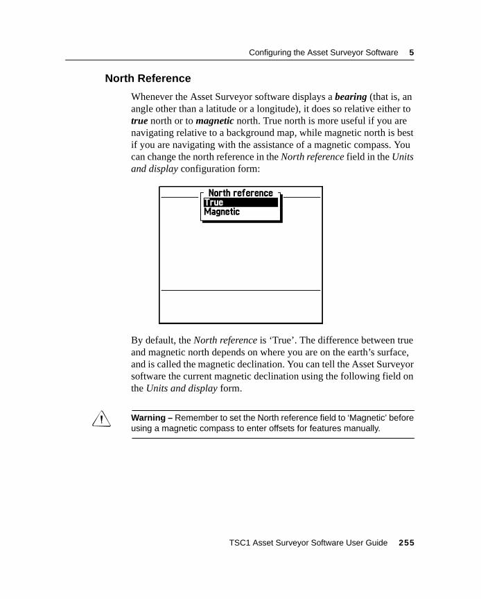
Configuring the Asset Surveyor Software 5
5.8.4 North Reference
Whenever the Asset Surveyor software displays a bearing (that is, anangle other than a latitude or a longitude), it does so relative either totrue north or to magnetic north. True north is more useful if you arenavigating relative to a background map, while magnetic north is bestif you are navigating with the assistance of a magnetic compass. Youcan change the north reference in the North reference field in the Unitsand display configuration form:
By default, the North reference is ‘True’. The difference between trueand magnetic north depends on where you are on the earth’s surface,and is called the magnetic declination. You can tell the Asset Surveyorsoftware the current magnetic declination using the following field onthe Units and display form.
C Warning – Remember to set the North reference field to ‘Magnetic’ beforeusing a magnetic compass to enter offsets for features manually.
TSC1 Asset Surveyor Software User Guide 255
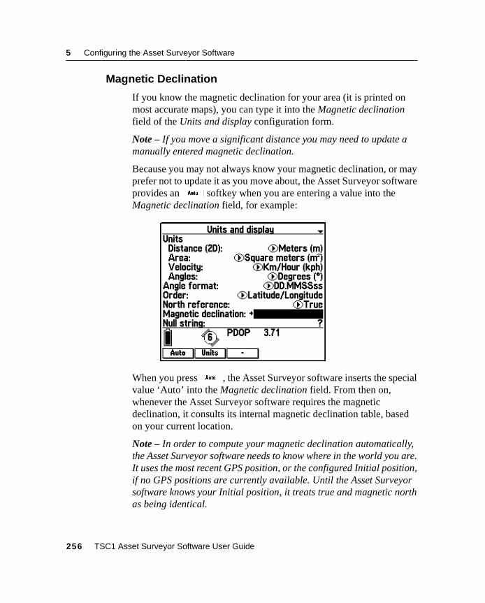
5 Configuring the Asset Surveyor Software
5.8.5 Magnetic Declination
If you know the magnetic declination for your area (it is printed onmost accurate maps), you can type it into the Magnetic declinationfield of the Units and display configuration form.
Note – If you move a significant distance you may need to update amanually entered magnetic declination.
Because you may not always know your magnetic declination, or mayprefer not to update it as you move about, the Asset Surveyor softwareprovides an$ softkey when you are entering a value into theMagnetic declination field, for example:
When you press$ , the Asset Surveyor software inserts the specialvalue ‘Auto’ into the Magnetic declination field. From then on,whenever the Asset Surveyor software requires the magneticdeclination, it consults its internal magnetic declination table, basedon your current location.
Note – In order to compute your magnetic declination automatically,the Asset Surveyor software needs to know where in the world you are.It uses the most recent GPS position, or the configured Initial position,if no GPS positions are currently available. Until the Asset Surveyorsoftware knows your Initial position, it treats true and magnetic northas being identical.
256 TSC1 Asset Surveyor Software User Guide
Configuring the Asset Surveyor Software 5
B Tip – You only need to enter explicit declinations when you are navigatingover reasonably large distances, entering magnetic offsets for features(with or without a laser rangefinder) or when there is a local variation inthe earth’s magnetic field. The Asset Surveyor software’s declination tablemodels the earth’s overall magnetic field. It does not take any account oflocal variations due to such things as mineral deposits. If you need totemporarily enter a precise declination for a particular area, remember tochange back to ‘Auto’ when you leave that area.
5.8.6 Null String
Whenever the Asset Surveyor software has no value for a particularfield in a form, it displays the null character string, which by default isthe single character ‘?’. Usually, you are not permitted to save a formif one or more of its fields still have the null value, but occasionally afield is permitted to remain null.
You can change the null character string by editing the Null stringfield in the Units and display configuration form. You can use anycharacter string for the null value, but the null string should bedistinctive and preferably brief.
When you are editing the Null string field, the Asset Surveyorsoftware displays two softkeys:
• You can pressW to change the Null string to a single spacecharacter.
• You can pressV to insert a special character.
TSC1 Asset Surveyor Software User Guide 257
5 Configuring the Asset Surveyor Software
5.8.7 Language
The Asset Surveyor software has been translated into a number ofEuropean languages that are pre-loaded onto the TSC1 datalogger.The language can be changed as desired by selecting them from theLanguage field’s pop-up menu. The Asset Surveyor software supportsthe following languages:
• English
• French
• German
• Portuguese
• Russian
• Spanish
The distribution CD-ROM for the Asset Surveyor software containseach of the language files supported at the time of purchase. If thelanguage you require is not on the CD-ROM, please contact yourTrimble distributor, as new translations of the Asset Surveyor softwaremay be available. For instructions on how to transfer new languagefiles onto your TSC1 datalogger, refer to the Data Transfer utilitydocumentation.
To delete an unwanted language, highlight it and pressd .
Note – The Asset Surveyor software does not let you delete the defaultlanguage, which is English.
Keypad
The Asset Surveyor software can be translated into languages that donot use the Roman alphabet (that is, A…Z). For example, the Russianlanguage uses the Cyrillic alphabet.
In order to use the Asset Surveyor software when running in alanguage such as Russian, it is necessary to map the TSC1datalogger’sa,b,c, …,z keys to letters in that language’snative alphabet, as shown in Figure 5.2.
258 TSC1 Asset Surveyor Software User Guide
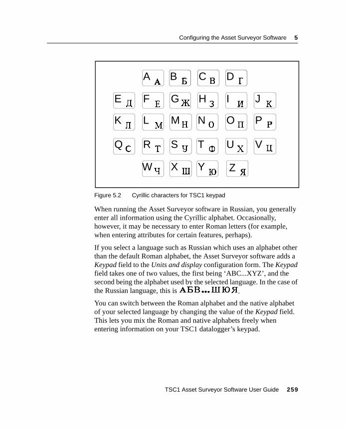
Configuring the Asset Surveyor Software 5
Figure 5.2 Cyrillic characters for TSC1 keypad
When running the Asset Surveyor software in Russian, you generallyenter all information using the Cyrillic alphabet. Occasionally,however, it may be necessary to enter Roman letters (for example,when entering attributes for certain features, perhaps).
If you select a language such as Russian which uses an alphabet otherthan the default Roman alphabet, the Asset Surveyor software adds aKeypad field to the Units and display configuration form. The Keypadfield takes one of two values, the first being ‘ABC...XYZ’, and thesecond being the alphabet used by the selected language. In the case ofthe Russian language, this is .
You can switch between the Roman alphabet and the native alphabetof your selected language by changing the value of the Keypad field.This lets you mix the Roman and native alphabets freely whenentering information on your TSC1 datalogger’s keypad.
A B C D
E F G H I J
K L M N O P
Q R S T U V
W X Y Z
TSC1 Asset Surveyor Software User Guide 259
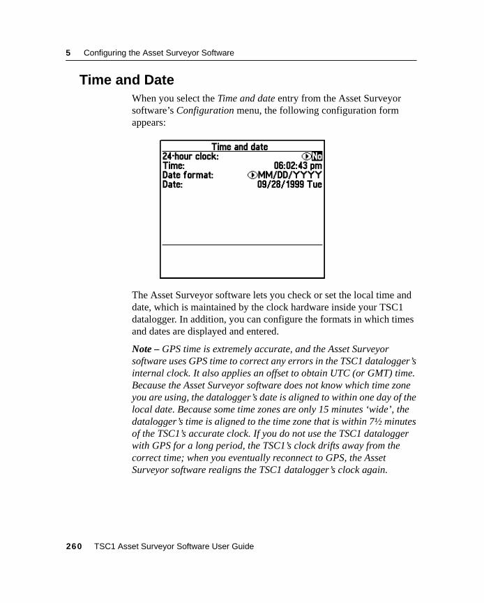
5 Configuring the Asset Surveyor Software
5.9 Time and DateWhen you select the Time and date entry from the Asset Surveyorsoftware’s Configuration menu, the following configuration formappears:
The Asset Surveyor software lets you check or set the local time anddate, which is maintained by the clock hardware inside your TSC1datalogger. In addition, you can configure the formats in which timesand dates are displayed and entered.
Note – GPS time is extremely accurate, and the Asset Surveyorsoftware uses GPS time to correct any errors in the TSC1 datalogger’sinternal clock. It also applies an offset to obtain UTC (or GMT) time.Because the Asset Surveyor software does not know which time zoneyou are using, the datalogger’s date is aligned to within one day of thelocal date. Because some time zones are only 15 minutes ‘wide’, thedatalogger’s time is aligned to the time zone that is within 7½ minutesof the TSC1’s accurate clock. If you do not use the TSC1 dataloggerwith GPS for a long period, the TSC1’s clock drifts away from thecorrect time; when you eventually reconnect to GPS, the AssetSurveyor software realigns the TSC1 datalogger’s clock again.
260 TSC1 Asset Surveyor Software User Guide
Configuring the Asset Surveyor Software 5
5.9.1 24-Hour Clock
The Asset Surveyor software can operate either using a 24-hour clockor a 12-hour clock (where A.M. and P.M. are used to distinguish timesin the morning from those in the afternoon). By default, the AssetSurveyor software operates in 12-hour mode, but if you want to viewand enter times in 24-hour format, you can change the value of the24-hour clock field to ‘Yes’.
Note – Remember that even if you view times in 12-hour format, youcan enter them in 24-hour format. The Asset Surveyor softwareautomatically converts them to 12-hour format before displayingthem.
5.9.2 Time
The Time field is used for setting the local time of the TSC1datalogger. When you open the Time and date configuration form, thisvalue is ticking over in pace with the TSC1 datalogger’s internalclock. If you change the time it ceases to tick over, and whatever timeyou have entered is used to set the TSC1 datalogger’s clock hardwarewhen the form is saved.
When you are entering a new time the Asset Surveyor software makesa number of useful softkeys available. For more information, see Timefields, page 43.
C Warning – Make sure that you enter the time correctly. If you are using a12-hour clock, make sure that you enter pm if appropriate.
Note – You can either configure the Time and Date fields to show thelocal time and date, or you can configure these fields to show UTCtime (also known as GMT). The local time and date are generallymore useful, especially if you want to record the current time and dateas attribute values. You can choose whether to name data files usinglocal or UTC time by pressing thet softkey in any of the Createfile forms.
TSC1 Asset Surveyor Software User Guide 261
5 Configuring the Asset Surveyor Software
5.9.3 Date Format
The three supported date formats are:
• MM/DD/YYYY
• DD/MM/YYYY
• YYYY/MM/DD
The Asset Surveyor software’s default format is ‘MM/DD/YYYY’.You can change the Asset Surveyor software’s date format by editingthe Date format field of the Time and date configuration form.
5.9.4 Date
The Date field is used for setting the local date of the TSC1datalogger.
When you are entering a new date, various useful softkeys are madeavailable. For more information, see Date fields, page 42.
When you turn your TSC1 datalogger on for the first time, and when itis turned on again after having had its batteries removed or discharged,the internal clock is set to January 1st, 1980. You should reset theclock before using the TSC1 datalogger for data logging, so that the8 andH softkeys and automatic time and date fields operatecorrectly.
262 TSC1 Asset Surveyor Software User Guide
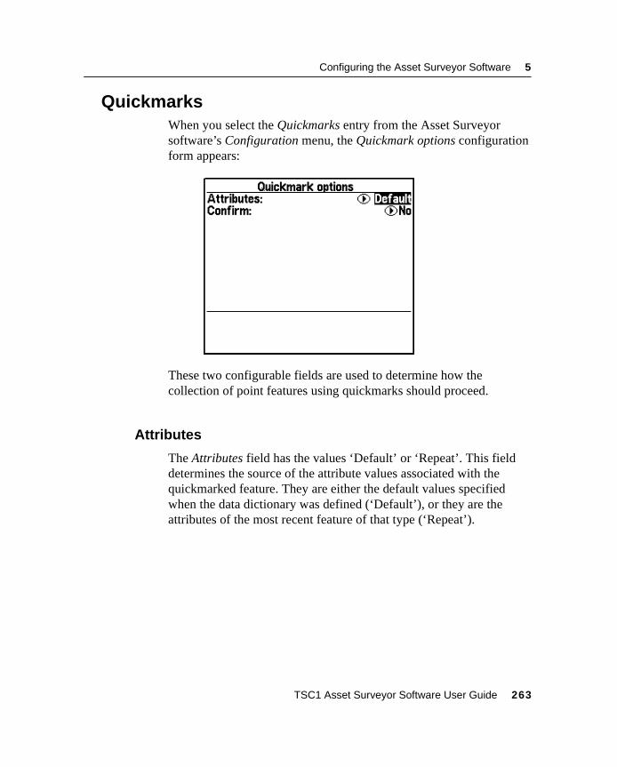
Configuring the Asset Surveyor Software 5
5.10QuickmarksWhen you select the Quickmarks entry from the Asset Surveyorsoftware’s Configuration menu, the Quickmark options configurationform appears:
These two configurable fields are used to determine how thecollection of point features using quickmarks should proceed.
5.10.1 Attributes
The Attributes field has the values ‘Default’ or ‘Repeat’. This fielddetermines the source of the attribute values associated with thequickmarked feature. They are either the default values specifiedwhen the data dictionary was defined (‘Default’), or they are theattributes of the most recent feature of that type (‘Repeat’).
TSC1 Asset Surveyor Software User Guide 263
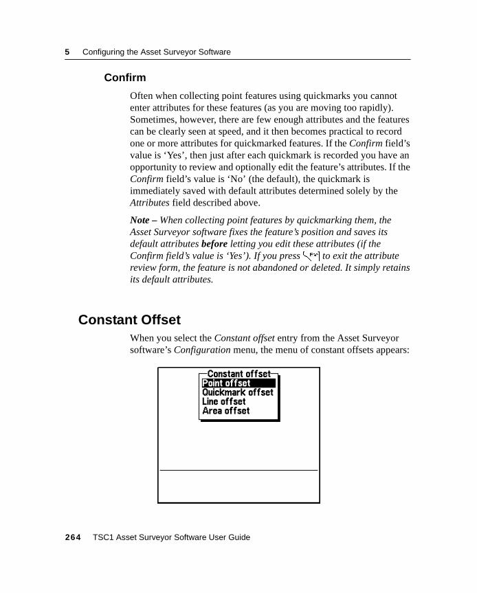
5 Configuring the Asset Surveyor Software
5.10.2 Confirm
Often when collecting point features using quickmarks you cannotenter attributes for these features (as you are moving too rapidly).Sometimes, however, there are few enough attributes and the featurescan be clearly seen at speed, and it then becomes practical to recordone or more attributes for quickmarked features. If the Confirm field’svalue is ‘Yes’, then just after each quickmark is recorded you have anopportunity to review and optionally edit the feature’s attributes. If theConfirm field’s value is ‘No’ (the default), the quickmark isimmediately saved with default attributes determined solely by theAttributes field described above.
Note – When collecting point features by quickmarking them, theAsset Surveyor software fixes the feature’s position and saves itsdefault attributes before letting you edit these attributes (if theConfirm field’s value is ‘Yes’). If you press= to exit the attributereview form, the feature is not abandoned or deleted. It simply retainsits default attributes.
5.11Constant OffsetWhen you select the Constant offset entry from the Asset Surveyorsoftware’s Configuration menu, the menu of constant offsets appears:
264 TSC1 Asset Surveyor Software User Guide
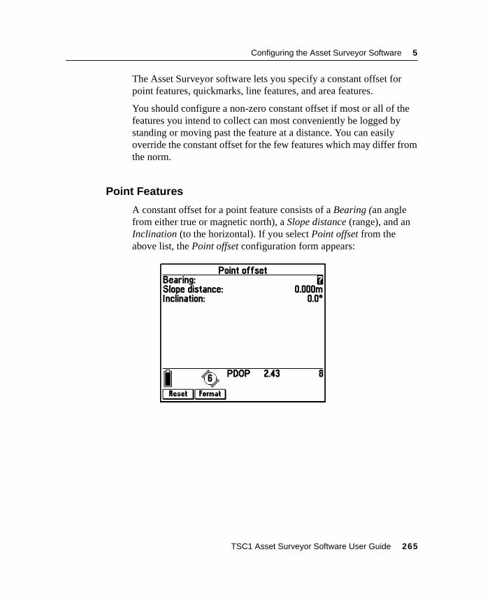
Configuring the Asset Surveyor Software 5
The Asset Surveyor software lets you specify a constant offset forpoint features, quickmarks, line features, and area features.
You should configure a non-zero constant offset if most or all of thefeatures you intend to collect can most conveniently be logged bystanding or moving past the feature at a distance. You can easilyoverride the constant offset for the few features which may differ fromthe norm.
5.11.1 Point Features
A constant offset for a point feature consists of a Bearing (an anglefrom either true or magnetic north), a Slope distance (range), and anInclination (to the horizontal). If you select Point offset from theabove list, the Point offset configuration form appears:
TSC1 Asset Surveyor Software User Guide 265
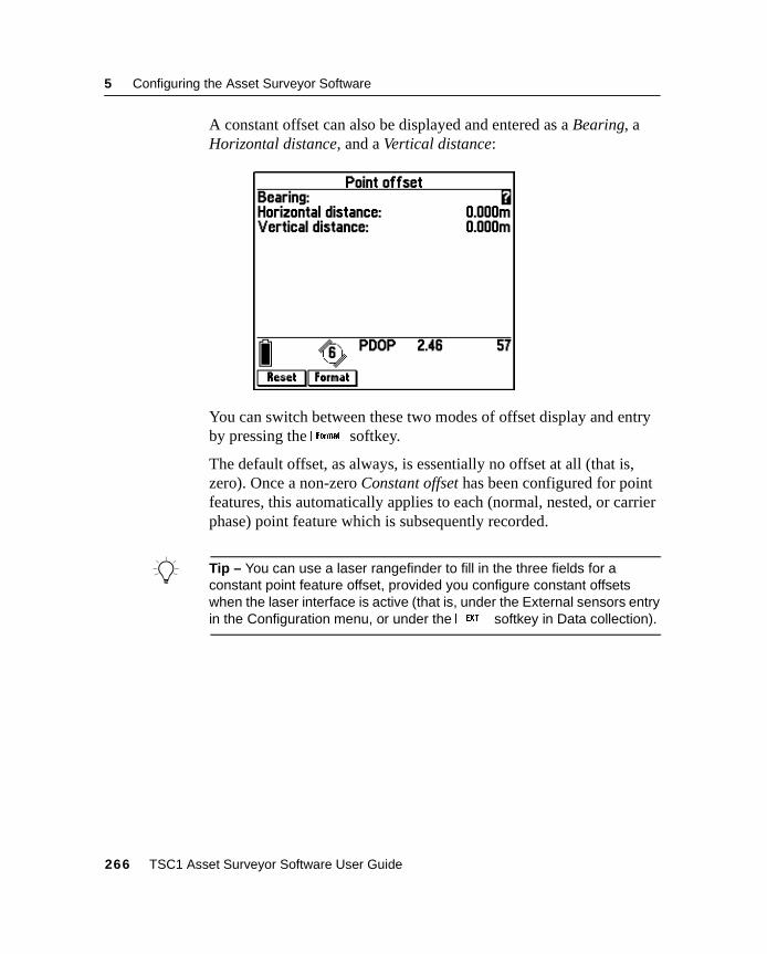
5 Configuring the Asset Surveyor Software
A constant offset can also be displayed and entered as a Bearing, aHorizontal distance, and a Vertical distance:
You can switch between these two modes of offset display and entryby pressing thef softkey.
The default offset, as always, is essentially no offset at all (that is,zero). Once a non-zero Constant offset has been configured for pointfeatures, this automatically applies to each (normal, nested, or carrierphase) point feature which is subsequently recorded.
B Tip – You can use a laser rangefinder to fill in the three fields for aconstant point feature offset, provided you configure constant offsetswhen the laser interface is active (that is, under the External sensors entryin the Configuration menu, or under theX softkey in Data collection).
266 TSC1 Asset Surveyor Software User Guide
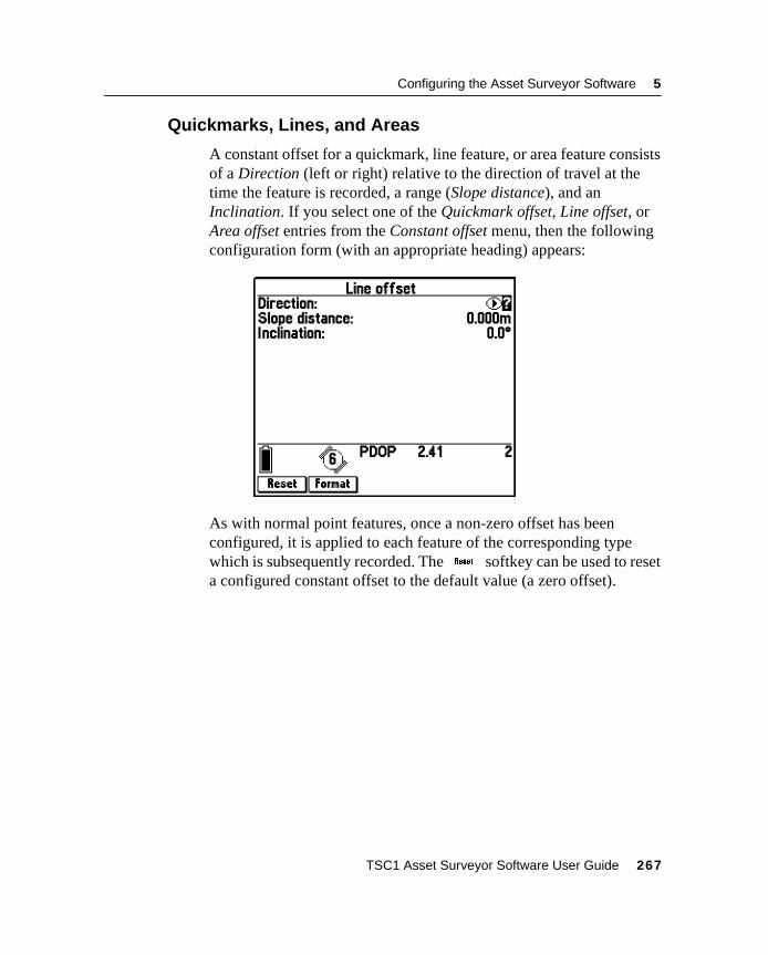
Configuring the Asset Surveyor Software 5
5.11.2 Quickmarks, Lines, and Areas
A constant offset for a quickmark, line feature, or area feature consistsof a Direction (left or right) relative to the direction of travel at thetime the feature is recorded, a range (Slope distance), and anInclination. If you select one of the Quickmark offset, Line offset, orArea offset entries from the Constant offset menu, then the followingconfiguration form (with an appropriate heading) appears:
As with normal point features, once a non-zero offset has beenconfigured, it is applied to each feature of the corresponding typewhich is subsequently recorded. TheK softkey can be used to reseta configured constant offset to the default value (a zero offset).
TSC1 Asset Surveyor Software User Guide 267
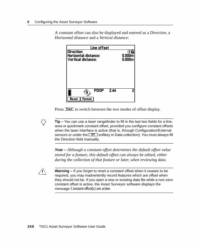
5 Configuring the Asset Surveyor Software
A constant offset can also be displayed and entered as a Direction, aHorizontal distance and a Vertical distance:
Pressf to switch between the two modes of offset display.
B Tip – You can use a laser rangefinder to fill in the last two fields for a line,area or quickmark constant offset, provided you configure constant offsetswhen the laser interface is active (that is, through Configuration/Externalsensors or under theX softkey in Data collection). You must always fillthe Direction field manually.
Note – Although a constant offset determines the default offset valuestored for a feature, this default offset can always be edited, eitherduring the collection of that feature or later, when reviewing data.
C Warning – If you forget to reset a constant offset when it ceases to berequired, you may inadvertently record features which are offset whenthey should not be. If you open a new or existing data file while a non-zeroconstant offset is active, the Asset Surveyor software displays themessage Constant offset(s) are active.
268 TSC1 Asset Surveyor Software User Guide
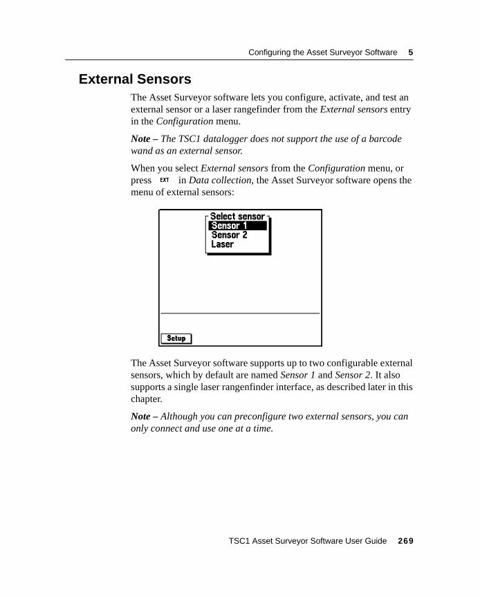
Configuring the Asset Surveyor Software 5
5.12External SensorsThe Asset Surveyor software lets you configure, activate, and test anexternal sensor or a laser rangefinder from the External sensors entryin the Configuration menu.
Note – The TSC1 datalogger does not support the use of a barcodewand as an external sensor.
When you select External sensors from the Configuration menu, orpressX in Data collection, the Asset Surveyor software opens themenu of external sensors:
The Asset Surveyor software supports up to two configurable externalsensors, which by default are named Sensor 1 and Sensor 2. It alsosupports a single laser rangenfinder interface, as described later in thischapter.
Note – Although you can preconfigure two external sensors, you canonly connect and use one at a time.
TSC1 Asset Surveyor Software User Guide 269
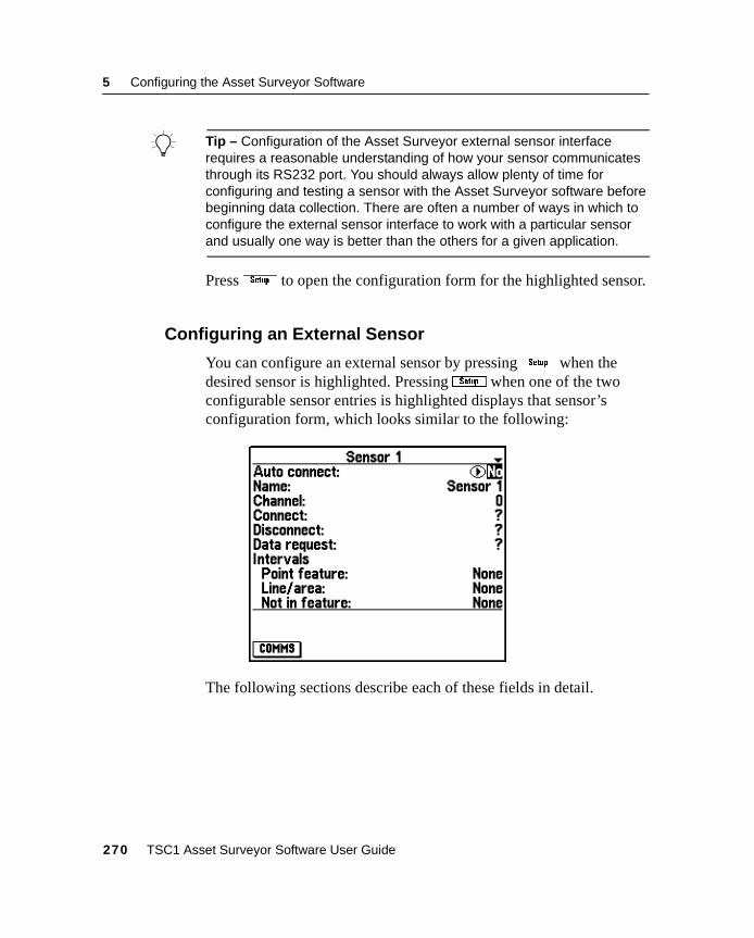
5 Configuring the Asset Surveyor Software
B Tip – Configuration of the Asset Surveyor external sensor interfacerequires a reasonable understanding of how your sensor communicatesthrough its RS232 port. You should always allow plenty of time forconfiguring and testing a sensor with the Asset Surveyor software beforebeginning data collection. There are often a number of ways in which toconfigure the external sensor interface to work with a particular sensorand usually one way is better than the others for a given application.
PressS to open the configuration form for the highlighted sensor.
5.12.1 Configuring an External Sensor
You can configure an external sensor by pressingS when thedesired sensor is highlighted. PressingS when one of the twoconfigurable sensor entries is highlighted displays that sensor’sconfiguration form, which looks similar to the following:
The following sections describe each of these fields in detail.
270 TSC1 Asset Surveyor Software User Guide
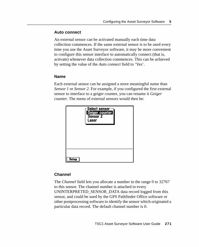
Configuring the Asset Surveyor Software 5
Auto connect
An external sensor can be activated manually each time datacollection commences. If the same external sensor is to be used everytime you use the Asset Surveyor software, it may be more convenientto configure this sensor interface to automatically connect (that is,activate) whenever data collection commences. This can be achievedby setting the value of the Auto connect field to ‘Yes’.
Name
Each external sensor can be assigned a more meaningful name thanSensor 1 or Sensor 2. For example, if you configured the first externalsensor to interface to a geiger counter, you can rename it Geigercounter. The menu of external sensors would then be:
Channel
The Channel field lets you allocate a number in the range 0 to 32767to this sensor. The channel number is attached to everyUNINTERPRETED_SENSOR_DATA data record logged from thissensor, and could be used by the GPS Pathfinder Office software orother postprocessing software to identify the sensor which originated aparticular data record. The default channel number is 0.
TSC1 Asset Surveyor Software User Guide 271
5 Configuring the Asset Surveyor Software
Note – The channel number is not related to the number of channels inyour GPS receiver, and neither is it related to radio frequencychannels. It is simply a number that you can assign to data receivedfrom a particular external sensor.
Connect and Disconnect
The Connect field specifies a character string which is automaticallysent by the Asset Surveyor software to the external sensor when theinterface with that sensor is activated. It might be used to reinitializethe sensor, or to set it into the correct mode.
The Disconnect field specifies a character string which isautomatically sent by the Asset Surveyor software to the externalsensor when the interface with that sensor is deactivated. It might beused to turn off the sensor, or reset its mode.
B Tip – If either the Connect or Disconnect fields has a null value, it is notsent to the external sensor. If you need to send to the sensor the samecharacter(s) that make up your configured null string, you must enter themas hexadecimal codes, as described below.
As with all configurable character strings which can be sent to orreceived from the external sensor, the Connect and Disconnect fieldslet you include both printable and non-printable ASCII characters.Non-printable ASCII characters are included in a field’s value using aspecial escape character (the backslash character, ‘\’).
When the backslash character is followed by two hexadecimal (base16) digits, it is treated as a single ASCII character with a valueequivalent to that two-digit hexadecimal number. For example:
• \01 is the hexadecimal value 0116, or ASCII character ‘1’.
• \4C is the hexadecimal value 4C16 or ASCII character ‘76’.This character corresponds to the letter ‘L’.
• \FF is the hexadecimal value FF16, or ‘255’.This is the largest ASCII character that can be specified.
272 TSC1 Asset Surveyor Software User Guide
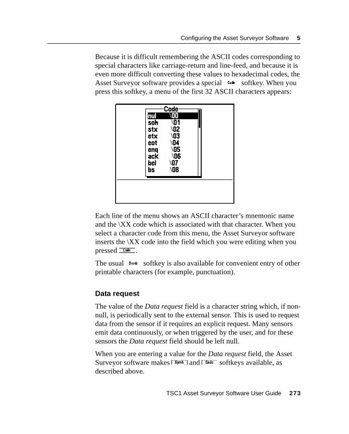
Configuring the Asset Surveyor Software 5
Because it is difficult remembering the ASCII codes corresponding tospecial characters like carriage-return and line-feed, and because it iseven more difficult converting these values to hexadecimal codes, theAsset Surveyor software provides a special% softkey. When youpress this softkey, a menu of the first 32 ASCII characters appears:
Each line of the menu shows an ASCII character’s mnemonic nameand the \XX code which is associated with that character. When youselect a character code from this menu, the Asset Surveyor softwareinserts the \XX code into the field which you were editing when youpressed% .
The usualV softkey is also available for convenient entry of otherprintable characters (for example, punctuation).
Data request
The value of the Data request field is a character string which, if non-null, is periodically sent to the external sensor. This is used to requestdata from the sensor if it requires an explicit request. Many sensorsemit data continuously, or when triggered by the user, and for thesesensors the Data request field should be left null.
When you are entering a value for the Data request field, the AssetSurveyor software makesV and% softkeys available, asdescribed above.
TSC1 Asset Surveyor Software User Guide 273
5 Configuring the Asset Surveyor Software
If non-null, the Data request string is periodically sent to the externalsensor as determined by the Intervals fields. All data emitted by theexternal sensor is then logged by the Asset Surveyor software.
If the Data request string is null, then whatever data is emitted by theexternal sensor is logged at a rate determined by the Intervals fields,described below.
Intervals
There are three intervals applying to point, line, or area features, andwhen not recording a feature. These intervals are used for one of twopurposes, depending on the value of the previous Data request field:
• If Data request is non-null, then depending on the context(whether in a feature or not, and if so, which type of feature),the appropriate interval is used to periodically send the Datarequest character string to the external sensor. In this case, anyresponse from the sensor is logged.
• If Data request is null, then data which just arrives from theexternal sensor unsolicited is logged at the interval appropriateto the context (whether in a feature or not, and if so, which typeof feature).
Note – If you have a sensor that emits unsolicited data, you do notneed to set up any kind of Data request string. However, you do needto set one or more of the Interval fields to a value other than ‘None’,otherwise the Asset Surveyor software does not log any data receivedfrom the sensor. When all intervals are set to ‘None’, the AssetSurveyor software does not log any data from an external sensor.
Note – As with all interval fields in the Asset Surveyor software, thesefields can be filled in by pressing0 or7 or by typing aninterval in seconds (or some other convenient unit of time).
274 TSC1 Asset Surveyor Software User Guide
Configuring the Asset Surveyor Software 5
Attribute
Data from an external sensor can be stored by the Asset Surveyorsoftware in one of two ways:
• As independent UNINTERPRETED_SENSOR_DATA records.These can be exported from the GPS Pathfinder Office softwarewith interpolated GPS positions, and fed into processingsoftware such as a contouring package. An example of anapplication that might store sensor data for contouring is aradiation survey where a Geiger counter is passed backwardsand forwards over a nuclear waste storage site.
• As attributes of a feature. When sensor data is stored as anattribute, it is tied to a particular geographic feature. It can beexported to a GIS along with all of the other attributes of thatfeature. An example of an application where sensor data shouldbe stored as attributes is a forestry survey where each tree has anumber of attributes, one of which is its trunk diameter, whichis measured using an electronic tree-caliper.
You specify which of these two methods of sensor data storage yourequire by configuring the Attribute field of the external sensorconfiguration form.
By default, the Attribute field has the special value ‘None’, whichmeans that sensor data is not stored as an attribute. Instead, it is storedas independent UNINTERPRETED_SENSOR_DATA records.
TSC1 Asset Surveyor Software User Guide 275
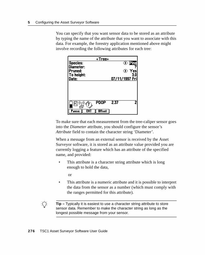
5 Configuring the Asset Surveyor Software
You can specify that you want sensor data to be stored as an attributeby typing the name of the attribute that you want to associate with thisdata. For example, the forestry application mentioned above mightinvolve recording the following attributes for each tree:
To make sure that each measurement from the tree-caliper sensor goesinto the Diameter attribute, you should configure the sensor’sAttribute field to contain the character string ‘Diameter’.
When a message from an external sensor is received by the AssetSurveyor software, it is stored as an attribute value provided you arecurrently logging a feature which has an attribute of the specifiedname, and provided:
• This attribute is a character string attribute which is longenough to hold the data,
or
• This attribute is a numeric attribute and it is possible to interpretthe data from the sensor as a number (which must comply withthe ranges permitted for this attribute).
B Tip – Typically it is easiest to use a character string attribute to storesensor data. Remember to make the character string as long as thelongest possible message from your sensor.
276 TSC1 Asset Surveyor Software User Guide
Configuring the Asset Surveyor Software 5
C Warning – You must take care to make sure that the character stringwhich you enter into the Attribute field exactly matches an attribute namein your current data dictionary. If it does not, the Asset Surveyor softwarefails to store data from your external sensor into any attribute field.Attribute name-matching is not case sensitive.
Note – More than one sensor data message may arrive during thecollection of a particular feature. Each time a message arrives, theAsset Surveyor software overwrites the value stored in the namedAttribute. Therefore only the last sensor message per feature isactually saved (when the feature itself is saved).
Note – When Attribute is set to ‘None’, and the Asset Surveyorsoftware is storing external sensor data asUNINTERPRETED_SENSOR_DATA records, the Asset Surveyorsoftware attempts to bracket each such record with at least two GPSpositions (just as it does for quickmarks). This enables the GPSPathfinder Office software to compute an interpolated GPS positionfor each external sensor data record, based on the time at which thatrecord was recorded.
TSC1 Asset Surveyor Software User Guide 277
5 Configuring the Asset Surveyor Software
Data received
The most complex part of configuring an external sensor interface isthe description of the data stream which is emitted by the sensor. Datacan be received from the sensor in response to a request, in acontinuous stream, or when a switch or trigger is pressed on the sensoritself.
In order to correctly separate the messages which are emitted by thesensor, the Asset Surveyor software lets you describe how messagesare structured using any combination of the following four fields:
• The Prefix field can be used to specify that each message fromthe sensor is prefixed with a constant sequence of characters.For example, all NMEA-compliant sensors output messagespreceded with a ‘$’ character and one or more characters whichidentify the specific sensor. Enter the null string if you do notwant to specify a prefix.
• The Suffix field can be used to specify that each message fromthe sensor ends with a constant sequence of characters. Forexample, all NMEA-compliant sensors output messagesterminated by carriage-return and line-feed characters. Enter thenull string if you do not want to specify a suffix.
• The Max bytes field can be used to limit the length of eachmessage to a specific number of bytes. This length includes thelength of any defined Prefix or Suffix strings, and the AssetSurveyor software does not let you specify a maximum numberof bytes which is less than the combined length of the prefix andsuffix. Enter the null string (by pressingl) if you do notwant to specify a maximum number of bytes. The maximumvalue for the Max bytes is 242 (this is the limit permitted forUNINTERPRETED_SENSOR_DATA SSF records).
278 TSC1 Asset Surveyor Software User Guide
Configuring the Asset Surveyor Software 5
• The Timeout field can be used to distinguish separate messagesby a certain amount of elapsed time between them. When theAsset Surveyor software receives a character from the sensor, itstarts a timer. If another character is not received from thesensor before the timer expires (that is, before Timeout secondshave elapsed), the Asset Surveyor software considers themessage is complete, and logs the characters it has received. If acharacter arrives before the timer expires, the timer is reset andthe procedure repeats.
The default value for the Timeout field is 0.1 seconds (100 ms);the maximum permitted value is 0.5 seconds and the minimumis 0.0 seconds.
C Warning – While the Asset Surveyor software is waiting for a Timeoutperiod, it cannot communicate with the GPS receiver. Do not specify alarge Timeout value unless you need it to process data from a particularexternal sensor.
The Asset Surveyor software uses a combination of the above fields toseparate messages from an external sensor.
Note – You do not necessarily need to fill in all of these fields. A fieldis ignored by the Asset Surveyor software if its value is null.
Audible click
If you want the TSC1 datalogger to click each time data from anexternal sensor is received and logged, set the value of the Audibleclick field to ‘Yes’.
TSC1 Asset Surveyor Software User Guide 279
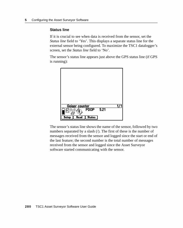
5 Configuring the Asset Surveyor Software
Status line
If it is crucial to see when data is received from the sensor, set theStatus line field to ‘Yes’. This displays a separate status line for theexternal sensor being configured. To maximize the TSC1 datalogger’sscreen, set the Status line field to ‘No’.
The sensor’s status line appears just above the GPS status line (if GPSis running):
The sensor’s status line shows the name of the sensor, followed by twonumbers separated by a slash (/). The first of these is the number ofmessages received from the sensor and logged since the start or end ofthe last feature; the second number is the total number of messagesreceived from the sensor and logged since the Asset Surveyorsoftware started communicating with the sensor.
280 TSC1 Asset Surveyor Software User Guide
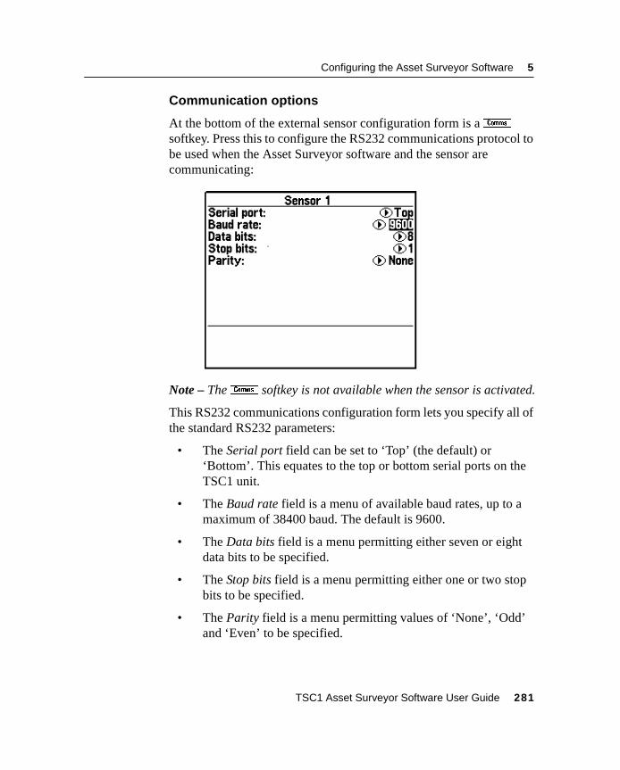
Configuring the Asset Surveyor Software 5
Communication options
At the bottom of the external sensor configuration form is amsoftkey. Press this to configure the RS232 communications protocol tobe used when the Asset Surveyor software and the sensor arecommunicating:
Note – Them softkey is not available when the sensor is activated.
This RS232 communications configuration form lets you specify all ofthe standard RS232 parameters:
• The Serial port field can be set to ‘Top’ (the default) or‘Bottom’. This equates to the top or bottom serial ports on theTSC1 unit.
• The Baud rate field is a menu of available baud rates, up to amaximum of 38400 baud. The default is 9600.
• The Data bits field is a menu permitting either seven or eightdata bits to be specified.
• The Stop bits field is a menu permitting either one or two stopbits to be specified.
• The Parity field is a menu permitting values of ‘None’, ‘Odd’and ‘Even’ to be specified.
TSC1 Asset Surveyor Software User Guide 281
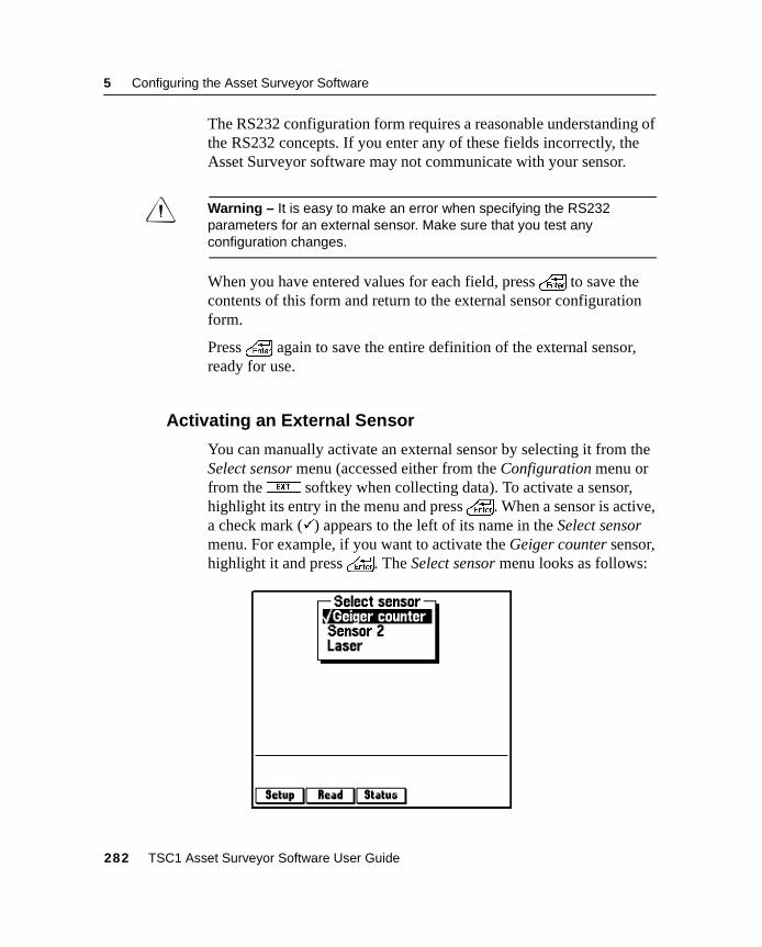
5 Configuring the Asset Surveyor Software
The RS232 configuration form requires a reasonable understanding ofthe RS232 concepts. If you enter any of these fields incorrectly, theAsset Surveyor software may not communicate with your sensor.
C Warning – It is easy to make an error when specifying the RS232parameters for an external sensor. Make sure that you test anyconfiguration changes.
When you have entered values for each field, press\ to save thecontents of this form and return to the external sensor configurationform.
Press\ again to save the entire definition of the external sensor,ready for use.
5.12.2 Activating an External Sensor
You can manually activate an external sensor by selecting it from theSelect sensor menu (accessed either from the Configuration menu orfrom theX softkey when collecting data). To activate a sensor,highlight its entry in the menu and press\. When a sensor is active,a check mark (�) appears to the left of its name in the Select sensormenu. For example, if you want to activate the Geiger counter sensor,highlight it and press\. The Select sensor menu looks as follows:
282 TSC1 Asset Surveyor Software User Guide
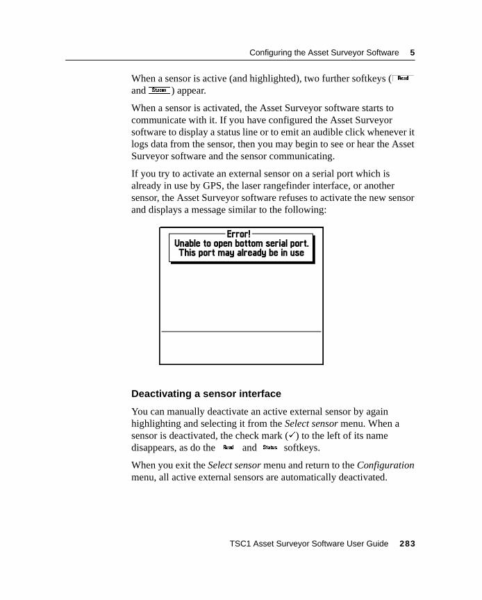
Configuring the Asset Surveyor Software 5
When a sensor is active (and highlighted), two further softkeys (randZ) appear.
When a sensor is activated, the Asset Surveyor software starts tocommunicate with it. If you have configured the Asset Surveyorsoftware to display a status line or to emit an audible click whenever itlogs data from the sensor, then you may begin to see or hear the AssetSurveyor software and the sensor communicating.
If you try to activate an external sensor on a serial port which isalready in use by GPS, the laser rangefinder interface, or anothersensor, the Asset Surveyor software refuses to activate the new sensorand displays a message similar to the following:
Deactivating a sensor interface
You can manually deactivate an active external sensor by againhighlighting and selecting it from the Select sensor menu. When asensor is deactivated, the check mark (�) to the left of its namedisappears, as do ther andZ softkeys.
When you exit the Select sensor menu and return to the Configurationmenu, all active external sensors are automatically deactivated.
TSC1 Asset Surveyor Software User Guide 283
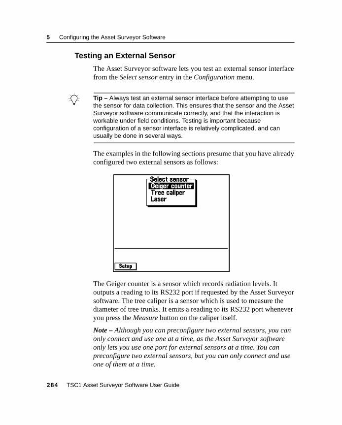
5 Configuring the Asset Surveyor Software
5.12.3 Testing an External Sensor
The Asset Surveyor software lets you test an external sensor interfacefrom the Select sensor entry in the Configuration menu.
B Tip – Always test an external sensor interface before attempting to usethe sensor for data collection. This ensures that the sensor and the AssetSurveyor software communicate correctly, and that the interaction isworkable under field conditions. Testing is important becauseconfiguration of a sensor interface is relatively complicated, and canusually be done in several ways.
The examples in the following sections presume that you have alreadyconfigured two external sensors as follows:
The Geiger counter is a sensor which records radiation levels. Itoutputs a reading to its RS232 port if requested by the Asset Surveyorsoftware. The tree caliper is a sensor which is used to measure thediameter of tree trunks. It emits a reading to its RS232 port wheneveryou press the Measure button on the caliper itself.
Note – Although you can preconfigure two external sensors, you canonly connect and use one at a time, as the Asset Surveyor softwareonly lets you use one port for external sensors at a time. You canpreconfigure two external sensors, but you can only connect and useone of them at a time.
284 TSC1 Asset Surveyor Software User Guide
Configuring the Asset Surveyor Software 5
Reading from a sensor
If an active sensor emits unsolicited data, you are unable to manuallyrequest data from the sensor; the Asset Surveyor software logs data asit is received, using the configured logging Intervals for that sensor.As an example, most depth-sounders operate in this fashion, emittingone or more readings per second.
If an active sensor emits data only when a trigger or button is pressedon the sensor itself, you cannot manually request data from the sensorusing the Asset Surveyor software. A typical example of a triggeredsensor is an electronic tree caliper.
If the sensor emits data only when requested over its RS232 line, theAsset Surveyor software can obtain data from the sensor by sendingthe configured Data request string. This is sent to the sensor in twocircumstances:
• As determined by the configured Interval fields (the Not infeature interval is used).
• When you press ther softkey.
B Tip – If the sensor is of the type where you want to take only one readingper feature, or very few readings, and you need to be able to trigger thereadings at precise moments, configure the sensor with intervals of‘None’, and use ther softkey to take readings when required.
TSC1 Asset Surveyor Software User Guide 285
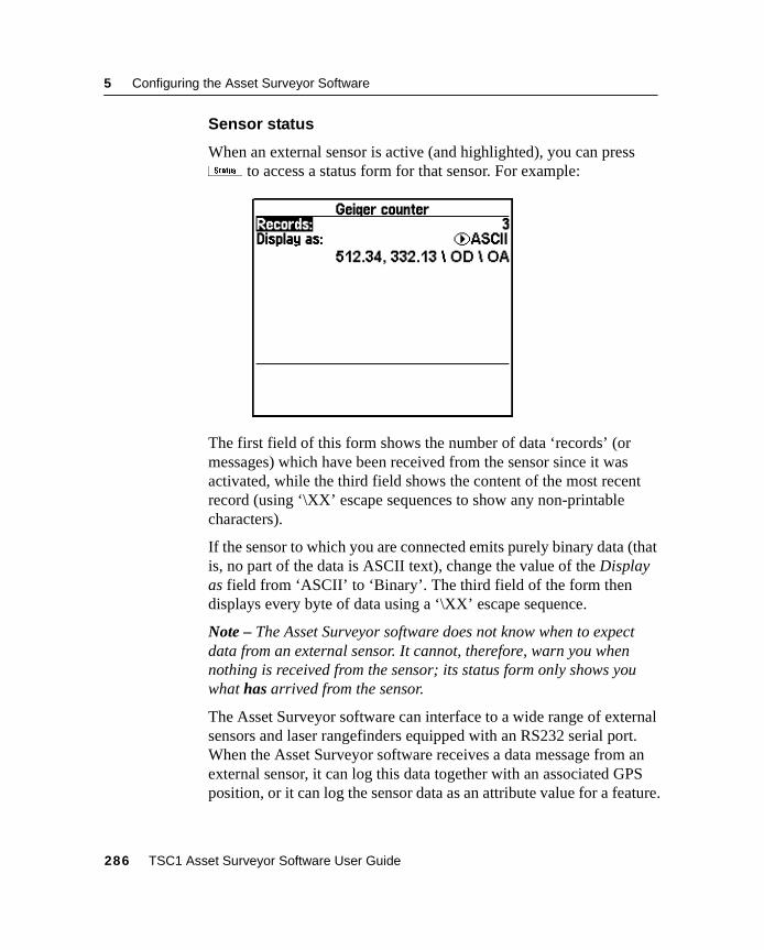
5 Configuring the Asset Surveyor Software
Sensor status
When an external sensor is active (and highlighted), you can pressZ to access a status form for that sensor. For example:
The first field of this form shows the number of data ‘records’ (ormessages) which have been received from the sensor since it wasactivated, while the third field shows the content of the most recentrecord (using ‘\XX’ escape sequences to show any non-printablecharacters).
If the sensor to which you are connected emits purely binary data (thatis, no part of the data is ASCII text), change the value of the Displayas field from ‘ASCII’ to ‘Binary’. The third field of the form thendisplays every byte of data using a ‘\XX’ escape sequence.
Note – The Asset Surveyor software does not know when to expectdata from an external sensor. It cannot, therefore, warn you whennothing is received from the sensor; its status form only shows youwhat has arrived from the sensor.
The Asset Surveyor software can interface to a wide range of externalsensors and laser rangefinders equipped with an RS232 serial port.When the Asset Surveyor software receives a data message from anexternal sensor, it can log this data together with an associated GPSposition, or it can log the sensor data as an attribute value for a feature.
286 TSC1 Asset Surveyor Software User Guide
Configuring the Asset Surveyor Software 5
Storage of sensor data
If data from a sensor is logged together with a GPS position, eachsensor data message is logged as a separateUNINTERPRETED_SENSOR_DATA record in the Trimble SSF fileformat. You can use the GPS Pathfinder Office Export utility to outputUNINTERPRETED_SENSOR_DATA records together with theirassociated GPS position. To ensure that the GPS position associatedwith each sensor message is as accurate as possible, the AssetSurveyor software records two GPS positions to ‘bracket’ the sensormessage (just as it does for quickmarks) and the GPS PathfinderOffice software uses a GPS time tag which is fixed to eachUNINTERPRETED_SENSOR_DATA record to compute aninterpolated GPS position for that record.
If a sensor message is stored as an attribute of a feature, it is stored inthe same way as any other attribute. From that point on, the AssetSurveyor software and the GPS Pathfinder Office software treat it as ifyou had typed it in, and you are free to edit the message if you want.
Sensor messages are not actually interpreted by the Asset Surveyorsoftware, whether they are stored asUNINTERPRETED_SENSOR_DATA records or as the attributes offeatures. You may need to edit these messages using the Export utility,or you may be able to write a program or script which transforms theraw sensor data into a more readable or usable format once the datahas been imported into your GIS, database, or CAD package.
TSC1 Asset Surveyor Software User Guide 287
5 Configuring the Asset Surveyor Software
Limitations of the Asset Surveyor external sensor interface
The Asset Surveyor software may not work with a particular externalsensor unless each of the following conditions is met:
• The sensor must emit ASCII (7- or 8-bit) characters; the AssetSurveyor software does not support the use of an RS232 line totransmit other electronic pulses.
• The sensor must emit distinct messages of no more than256 characters each. Each message can be as small as a singlecharacter.
• The sensor must emit messages which can be delimited eitherby a recognizable prefix, a recognizable suffix, a maximumlength or an elapsed period of time between messages. If thesensor emits messages whose format cannot be described interms of these factors, the Asset Surveyor software cannotdetermine where one message ends and the next begins.
• The sensor must not emit messages faster than the AssetSurveyor software can process them. The actual throughput thatcan be handled by the Asset Surveyor software depends on anumber of factors, including:
– The connected GPS receiver
– The prevailing GPS conditions (that is, number of visiblesatellites)
– The amount of GPS data being logged
– The nature of the messages being received from theexternal sensor (such as the way in which they aredelimited and the length of each message)
B Tip – Trimble recommends that before purchasing an external sensor, youshould always test the sensor with your Trimble Asset Surveyor/GPSsystem under a range of conditions to ascertain that the combinationperforms acceptably.
288 TSC1 Asset Surveyor Software User Guide

Configuring the Asset Surveyor Software 5
5.12.4 Configuring a Laser Rangefinder
You can configure an external sensor by pressingS when thedesired sensor is highlighted. PressingS when the laser entry ishighlighted displays the Laser range-finder configuration form, whichlooks as follows:
The following sections describe each of these fields in detail:
• Type: The laser Type field contains the values of ‘Criterion 300’,‘Criterion 400’, ‘ProSurvey 1000’, ‘Atlanta Advantage’,‘LEDHA-GEO’, or ‘MDL LaserAce 300’.
• Auto connect: The laser interface can be configured toAuto-connect whenever you create or reopen a rover data file;this can be useful if you often or always use the Asset Surveyorsoftware together with a laser rangefinder.
• Serial port: Select either ‘Top’ or ‘Bottom’ for the Serial portdepending on which port you have the laser plugged into.
Once you have selected the type of laser rangefinder, specifiedwhether or not it should automatically connect, and entered which portto receive the data from, no further configuration of the laserrangefinder interface is required. Press\ to save the laser interfaceconfiguration form and return to the menu of external sensors.
TSC1 Asset Surveyor Software User Guide 289
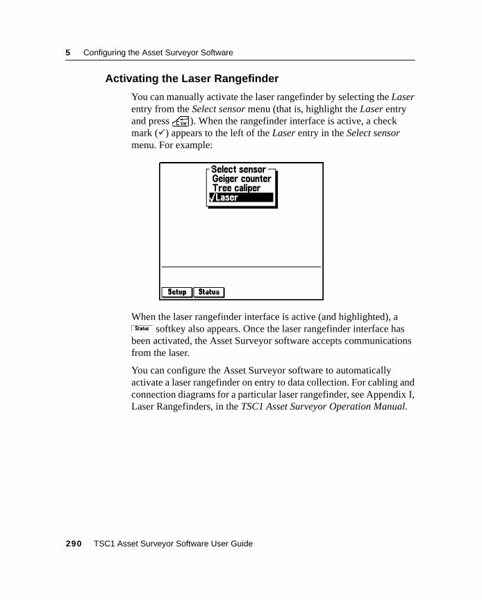
5 Configuring the Asset Surveyor Software
5.12.5 Activating the Laser Rangefinder
You can manually activate the laser rangefinder by selecting the Laserentry from the Select sensor menu (that is, highlight the Laser entryand press\). When the rangefinder interface is active, a checkmark (�) appears to the left of the Laser entry in the Select sensormenu. For example:
When the laser rangefinder interface is active (and highlighted), aZ softkey also appears. Once the laser rangefinder interface hasbeen activated, the Asset Surveyor software accepts communicationsfrom the laser.
You can configure the Asset Surveyor software to automaticallyactivate a laser rangefinder on entry to data collection. For cabling andconnection diagrams for a particular laser rangefinder, see Appendix I,Laser Rangefinders, in the TSC1 Asset Surveyor Operation Manual.
290 TSC1 Asset Surveyor Software User Guide
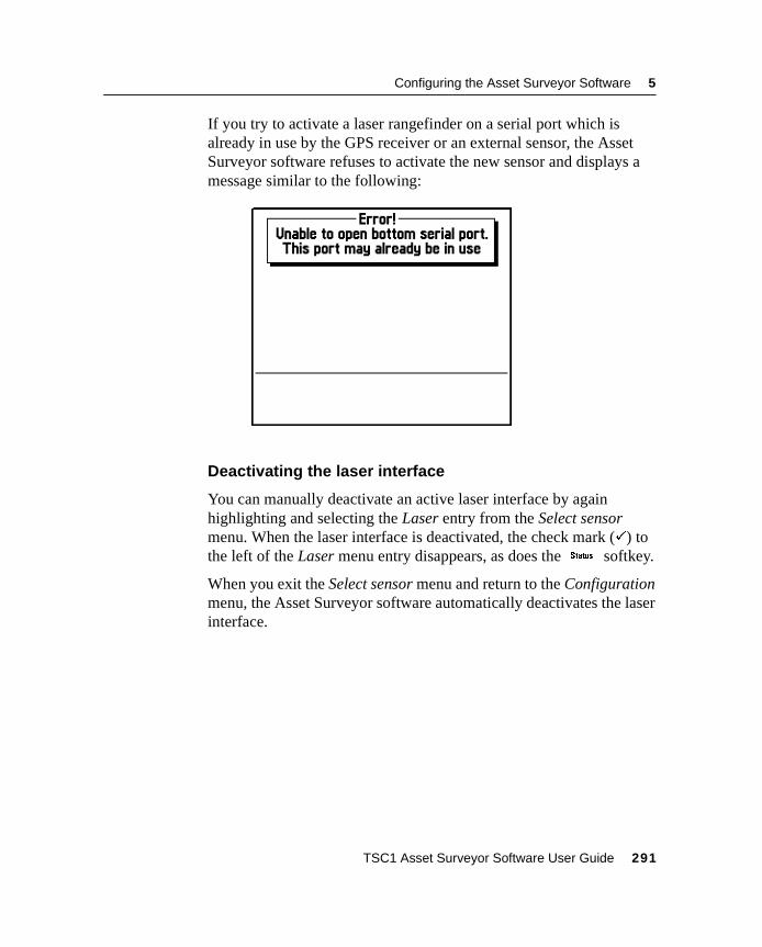
Configuring the Asset Surveyor Software 5
If you try to activate a laser rangefinder on a serial port which isalready in use by the GPS receiver or an external sensor, the AssetSurveyor software refuses to activate the new sensor and displays amessage similar to the following:
Deactivating the laser interface
You can manually deactivate an active laser interface by againhighlighting and selecting the Laser entry from the Select sensormenu. When the laser interface is deactivated, the check mark (�) tothe left of the Laser menu entry disappears, as does theZ softkey.
When you exit the Select sensor menu and return to the Configurationmenu, the Asset Surveyor software automatically deactivates the laserinterface.
TSC1 Asset Surveyor Software User Guide 291
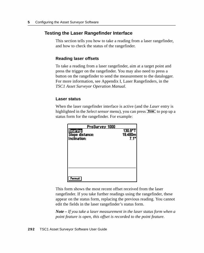
5 Configuring the Asset Surveyor Software
5.12.6 Testing the Laser Rangefinder Interface
This section tells you how to take a reading from a laser rangefinder,and how to check the status of the rangefinder.
Reading laser offsets
To take a reading from a laser rangefinder, aim at a target point andpress the trigger on the rangefinder. You may also need to press abutton on the rangefinder to send the measurement to the datalogger.For more information, see Appendix I, Laser Rangefinders, in theTSC1 Asset Surveyor Operation Manual.
Laser status
When the laser rangefinder interface is active (and the Laser entry ishighlighted in the Select sensor menu), you can pressZ to pop up astatus form for the rangefinder. For example:
This form shows the most recent offset received from the laserrangefinder. If you take further readings using the rangefinder, theseappear on the status form, replacing the previous reading. You cannotedit the fields in the laser rangefinder’s status form.
Note – If you take a laser measurement in the laser status form when apoint feature is open, this offset is recorded to the point feature.
292 TSC1 Asset Surveyor Software User Guide
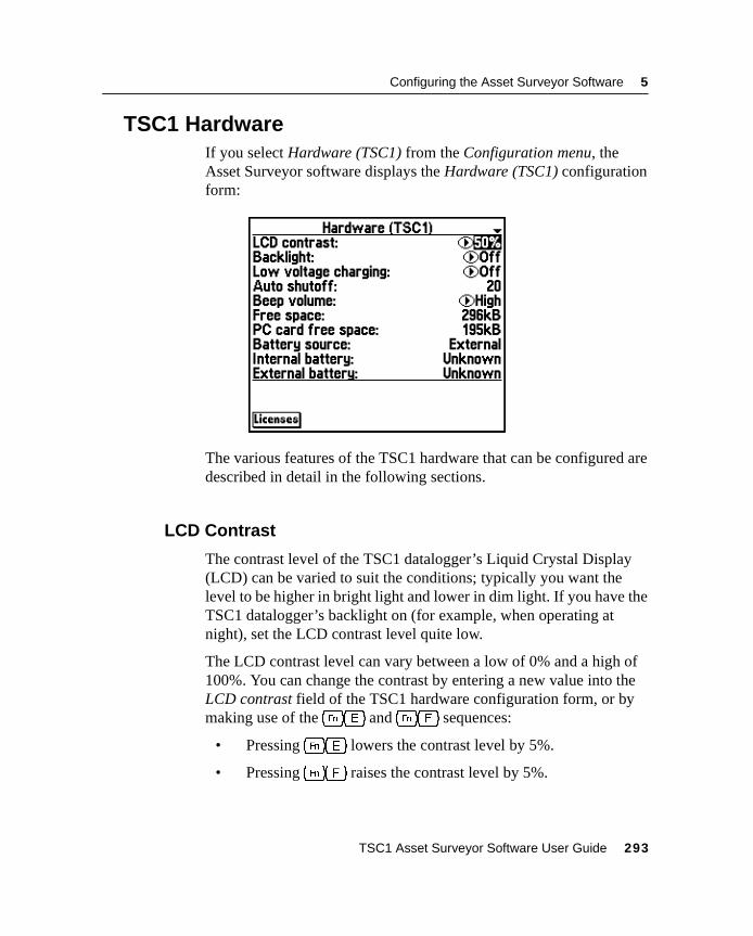
Configuring the Asset Surveyor Software 5
5.13TSC1 HardwareIf you select Hardware (TSC1) from the Configuration menu, theAsset Surveyor software displays the Hardware (TSC1) configurationform:
The various features of the TSC1 hardware that can be configured aredescribed in detail in the following sections.
5.13.1 LCD Contrast
The contrast level of the TSC1 datalogger’s Liquid Crystal Display(LCD) can be varied to suit the conditions; typically you want thelevel to be higher in bright light and lower in dim light. If you have theTSC1 datalogger’s backlight on (for example, when operating atnight), set the LCD contrast level quite low.
The LCD contrast level can vary between a low of 0% and a high of100%. You can change the contrast by entering a new value into theLCD contrast field of the TSC1 hardware configuration form, or bymaking use of the[e and[f sequences:
• Pressing[e lowers the contrast level by 5%.
• Pressing[f raises the contrast level by 5%.
TSC1 Asset Surveyor Software User Guide 293
5 Configuring the Asset Surveyor Software
B Tip – The advantage of the[e and[f sequences is that you canuse them anywhere in the Asset Surveyor system. This can be particularlyimportant if you turn the TSC1 datalogger on in conditions which aredifferent from those in which it was previously used. The LCD screen maybe so dark or so light that it is barely readable. It is easier, under thesecircumstances, to press[e or[f a few times than it is tonavigate to the Hardware (TSC1) configuration form and change the valueof the LCD contrast field.
5.13.2 Backlight
You can turn the TSC1 datalogger’s backlight on or off by changingthe value of the Backlight field. You can also turn the backlight on oroff by pressing[l.
5.13.3 Low Voltage Charging
The Low voltage charging field lets you charge the internal battery ofthe TSC1 datalogger using a power source of less than 15 V. Bydefault, this is set to ‘Off’, so that the datalogger will not draw powerfrom your receiver batteries to charge the TSC1 battery during normaloperation. To enable low power charging (using a GPS receiver withan external power source or directly from a camcorder battery) set theLow voltage charging field to ‘On’.
5.13.4 Auto Shutoff
In order to maximize battery life, the TSC1 datalogger turns off if nokey is pressed for a period of time (unless it is operating as a GPS basestation, navigating, or logging data to a rover file, in which case it doesnot turn off automatically). The value of the Auto shutoff fielddetermines how long the TSC1 datalogger waits after you last presseda key on its keypad, before turning off. The minimum value permittedfor Auto shutoff is one minute and the maximum is 60 minutes. Thedefault value is 20 minutes.
294 TSC1 Asset Surveyor Software User Guide
Configuring the Asset Surveyor Software 5
Note – The Auto shutoff setting does not cause the TSC1 datalogger toturn off in File Transfer mode, but after 10 minutes of inactivity theAsset Surveyor software exits file transfer mode and returns to the Filemanager menu. Once File Transfer mode has been exited, the Autoshutoff setting again becomes active and turns off the TSC1datalogger after the specified time has elapsed unless you press a key.
Note – The Auto shutoff setting does not cause the TSC1 datalogger toturn off when the Data collection or Navigation modules are open, orduring software upgrade.
5.13.5 Beep Volume
Whenever the Asset Surveyor software emits a beep of any kind, itdoes so either at high or low volume. You can select the volume bychanging the value of the Beep volume field or turn it off altogether.
5.13.6 Free Space
The Free space field shows you how much data file storage spaceremains on your TSC1 datalogger. You cannot edit this field. Whenthe Asset Surveyor software is installed, but no data files have beentransferred to the TSC1 datalogger, there is approximately 1787 kBfree space.
5.13.7 PC Card Free Space
The PC card free space field shows you how much data file storagespace remains on the PC card, if one is available. You cannot edit thisfield.
TSC1 Asset Surveyor Software User Guide 295
5 Configuring the Asset Surveyor Software
5.13.8 Battery Fields
The next three fields of the TSC1 hardware configuration form cannotbe edited. They provide information regarding the power supply andbattery levels currently detected by the TSC1 hardware.
The Battery source field has values of ‘Internal’ (if the TSC1datalogger is running on its own internal batteries) or ‘External’ (if anexternal source of power, such as the GPS receiver’s battery, is beingused to run the TSC1 datalogger).
The Internal battery field indicates the level of charge remaining inthe TSC1 datalogger’s main internal batteries. This field is expressedas a percentage.
The External battery field shows the level of the external powersource (that is, GPS receiver battery), if applicable. This field is alsoexpressed as a percentage.
The level of charge is calculated by comparing the actual voltagereported with the theoretical voltage range for the battery type. Forexample, 12 V external batteries are compared to the range 10 V (adead battery) to 13 V (the maximum charge). The percentage iscalculated with the following formula:
% = (reported - minimum) / (maximum - minimum) × 100
So, for example, for a battery charged to 11.5 V:
% = (11.5 – 10) / (13 – 10) × 100
= 50%
Note – The percentage reported for new batteries may be less than100%. Used batteries may report percentages well under 100%. Thisis because repeated recharging of batteries normally results in areduced potential maximum voltage.
296 TSC1 Asset Surveyor Software User Guide
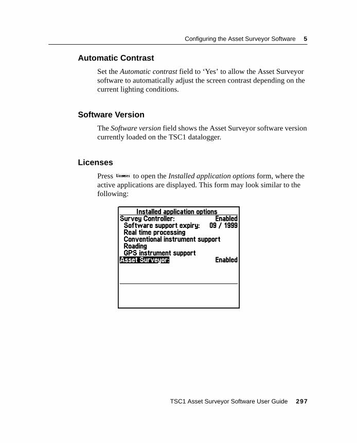
Configuring the Asset Surveyor Software 5
5.13.9 Automatic Contrast
Set the Automatic contrast field to ‘Yes’ to allow the Asset Surveyorsoftware to automatically adjust the screen contrast depending on thecurrent lighting conditions.
5.13.10 Software Version
The Software version field shows the Asset Surveyor software versioncurrently loaded on the TSC1 datalogger.
5.13.11 Licenses
Press* to open the Installed application options form, where theactive applications are displayed. This form may look similar to thefollowing:
TSC1 Asset Surveyor Software User Guide 297

5 Configuring the Asset Surveyor Software
298 TSC1 Asset Surveyor Software User Guide

C H A P T E R
6
6 UtilitiesIn this chapter:
■ Introduction
■ Waypoints
■ Factory defaults
■ Reset GPS receiver
■ Almanac
■ Disconnect/connect GPS
■ Entering a note
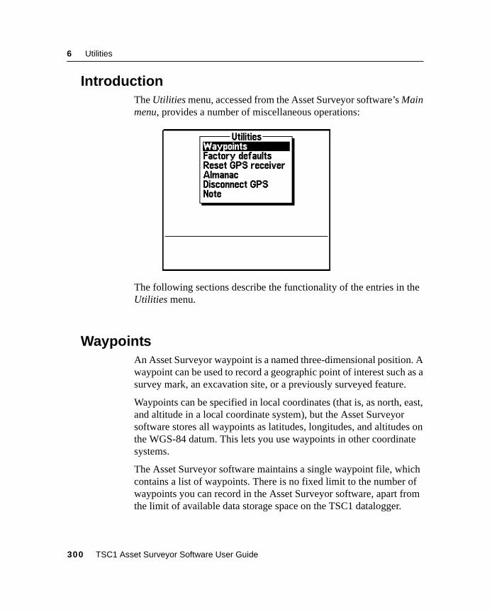
6 Utilities
6.1 IntroductionThe Utilities menu, accessed from the Asset Surveyor software’s Mainmenu, provides a number of miscellaneous operations:
The following sections describe the functionality of the entries in theUtilities menu.
6.2 WaypointsAn Asset Surveyor waypoint is a named three-dimensional position. Awaypoint can be used to record a geographic point of interest such as asurvey mark, an excavation site, or a previously surveyed feature.
Waypoints can be specified in local coordinates (that is, as north, east,and altitude in a local coordinate system), but the Asset Surveyorsoftware stores all waypoints as latitudes, longitudes, and altitudes onthe WGS-84 datum. This lets you use waypoints in other coordinatesystems.
The Asset Surveyor software maintains a single waypoint file, whichcontains a list of waypoints. There is no fixed limit to the number ofwaypoints you can record in the Asset Surveyor software, apart fromthe limit of available data storage space on the TSC1 datalogger.
300 TSC1 Asset Surveyor Software User Guide
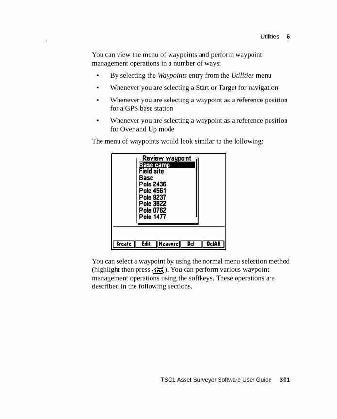
Utilities 6
You can view the menu of waypoints and perform waypointmanagement operations in a number of ways:
• By selecting the Waypoints entry from the Utilities menu
• Whenever you are selecting a Start or Target for navigation
• Whenever you are selecting a waypoint as a reference positionfor a GPS base station
• Whenever you are selecting a waypoint as a reference positionfor Over and Up mode
The menu of waypoints would look similar to the following:
You can select a waypoint by using the normal menu selection method(highlight then press\). You can perform various waypointmanagement operations using the softkeys. These operations aredescribed in the following sections.
TSC1 Asset Surveyor Software User Guide 301
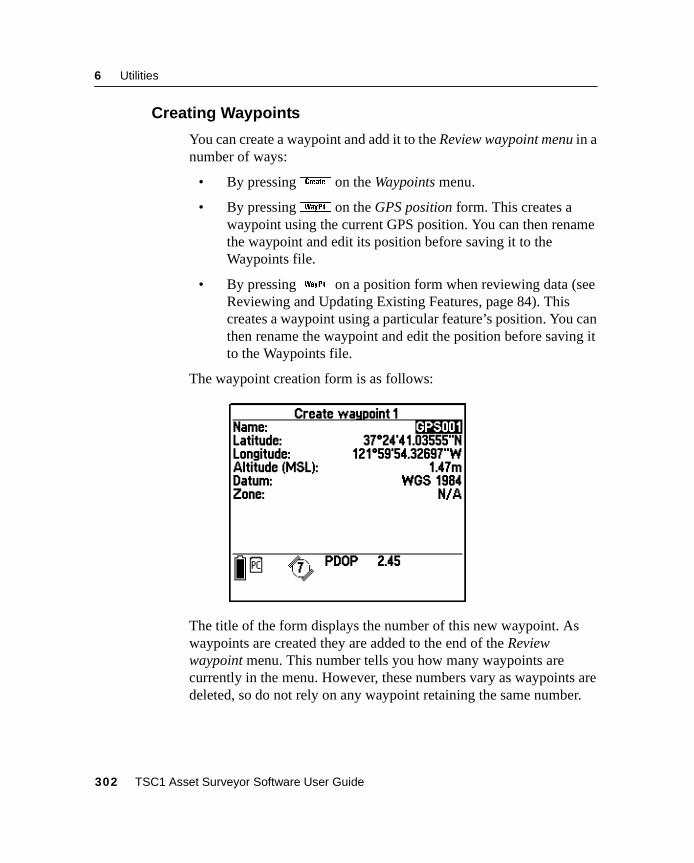
6 Utilities
6.2.1 Creating Waypoints
You can create a waypoint and add it to the Review waypoint menu in anumber of ways:
• By pressingB on the Waypoints menu.
• By pressingw on the GPS position form. This creates awaypoint using the current GPS position. You can then renamethe waypoint and edit its position before saving it to theWaypoints file.
• By pressingw on a position form when reviewing data (seeReviewing and Updating Existing Features, page 84). Thiscreates a waypoint using a particular feature’s position. You canthen rename the waypoint and edit the position before saving itto the Waypoints file.
The waypoint creation form is as follows:
The title of the form displays the number of this new waypoint. Aswaypoints are created they are added to the end of the Reviewwaypoint menu. This number tells you how many waypoints arecurrently in the menu. However, these numbers vary as waypoints aredeleted, so do not rely on any waypoint retaining the same number.
302 TSC1 Asset Surveyor Software User Guide
Utilities 6
Enter a waypoint’s name and location in the remaining fields on thisform. You must supply non-null values for all fields before pressing\ to save and add the waypoint to the Review waypoint menu.
Note – When entering waypoints from a map, you may have toestimate the waypoint’s altitude, using the map’s contours, or usingyour knowledge of the area; you cannot leave the altitude field empty.
B Tip – If you normally use one coordinate system and want to enterwaypoints from a map which uses a different coordinate system, switch tothe map’s coordinate system (using the Coordinate system entry on theConfiguration menu), enter the waypoints, then switch back to yournormal coordinate system. Because the Asset Surveyor software projectsall waypoints back to the WGS-84 datum, the positions can be used in anycoordinate system defined for that area. Although the actual coordinatesof a waypoint change when the coordinate system is changed, thephysical position of the waypoint is preserved.
The Create waypoint form supplies ah softkey which, when GPSis active, can be pressed to fill in the waypoint’s location with yourcurrent GPS position.
TSC1 Asset Surveyor Software User Guide 303
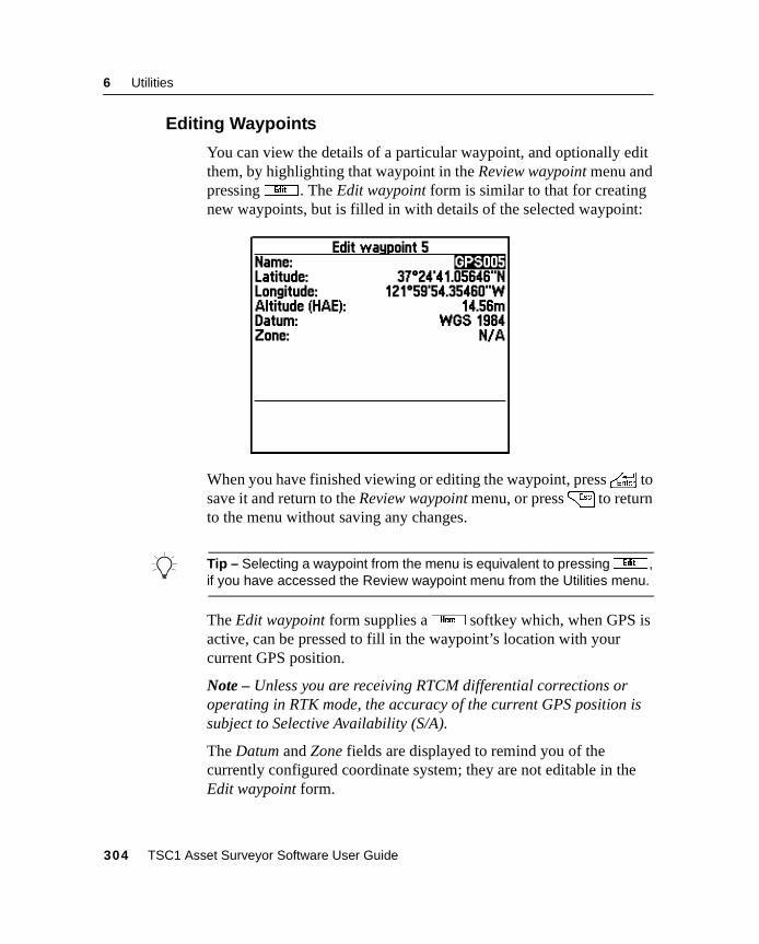
6 Utilities
6.2.2 Editing Waypoints
You can view the details of a particular waypoint, and optionally editthem, by highlighting that waypoint in the Review waypoint menu andpressinge . The Edit waypoint form is similar to that for creatingnew waypoints, but is filled in with details of the selected waypoint:
When you have finished viewing or editing the waypoint, press\ tosave it and return to the Review waypoint menu, or press= to returnto the menu without saving any changes.
B Tip – Selecting a waypoint from the menu is equivalent to pressinge ,if you have accessed the Review waypoint menu from the Utilities menu.
The Edit waypoint form supplies ah softkey which, when GPS isactive, can be pressed to fill in the waypoint’s location with yourcurrent GPS position.
Note – Unless you are receiving RTCM differential corrections oroperating in RTK mode, the accuracy of the current GPS position issubject to Selective Availability (S/A).
The Datum and Zone fields are displayed to remind you of thecurrently configured coordinate system; they are not editable in theEdit waypoint form.
304 TSC1 Asset Surveyor Software User Guide
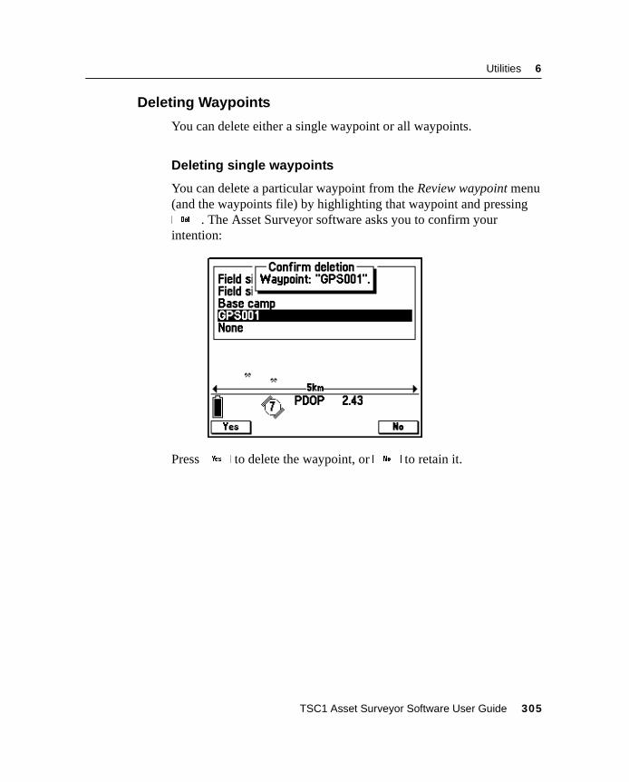
Utilities 6
6.2.3 Deleting Waypoints
You can delete either a single waypoint or all waypoints.
Deleting single waypoints
You can delete a particular waypoint from the Review waypoint menu(and the waypoints file) by highlighting that waypoint and pressingd . The Asset Surveyor software asks you to confirm yourintention:
Pressy to delete the waypoint, orn to retain it.
TSC1 Asset Surveyor Software User Guide 305
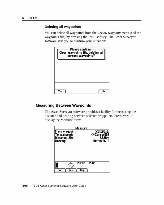
6 Utilities
Deleting all waypoints
You can delete all waypoints from the Review waypoint menu (and thewaypoints file) by pressing theD softkey. The Asset Surveyorsoftware asks you to confirm your intention:
6.2.4 Measuring Between Waypoints
The Asset Surveyor software provides a facility for measuring thedistance and bearing between selected waypoints. Pressx todisplay the Measure form:
306 TSC1 Asset Surveyor Software User Guide
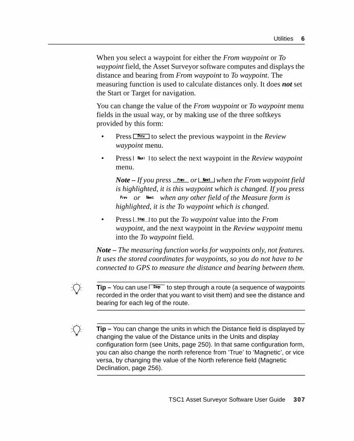
Utilities 6
When you select a waypoint for either the From waypoint or Towaypoint field, the Asset Surveyor software computes and displays thedistance and bearing from From waypoint to To waypoint. Themeasuring function is used to calculate distances only. It does not setthe Start or Target for navigation.
You can change the value of the From waypoint or To waypoint menufields in the usual way, or by making use of the three softkeysprovided by this form:
• Press[ to select the previous waypoint in the Reviewwaypoint menu.
• Press] to select the next waypoint in the Review waypointmenu.
Note – If you press[ or] when the From waypoint fieldis highlighted, it is this waypoint which is changed. If you press[ or] when any other field of the Measure form ishighlighted, it is the To waypoint which is changed.
• Press9 to put the To waypoint value into the Fromwaypoint, and the next waypoint in the Review waypoint menuinto the To waypoint field.
Note – The measuring function works for waypoints only, not features.It uses the stored coordinates for waypoints, so you do not have to beconnected to GPS to measure the distance and bearing between them.
B Tip – You can use9 to step through a route (a sequence of waypointsrecorded in the order that you want to visit them) and see the distance andbearing for each leg of the route.
B Tip – You can change the units in which the Distance field is displayed bychanging the value of the Distance units in the Units and displayconfiguration form (see Units, page 250). In that same configuration form,you can also change the north reference from ‘True’ to ‘Magnetic’, or viceversa, by changing the value of the North reference field (MagneticDeclination, page 256).
TSC1 Asset Surveyor Software User Guide 307
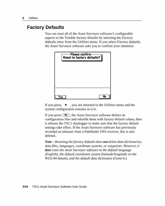
6 Utilities
6.3 Factory DefaultsYou can reset all of the Asset Surveyor software’s configurableaspects to the Trimble factory defaults by selecting the Factorydefaults entry from the Utilities menu. If you select Factory defaults,the Asset Surveyor software asks you to confirm your intention:
If you pressn , you are returned to the Utilities menu and thesystem configuration remains as it is.
If you pressy, the Asset Surveyor software deletes itsconfiguration files and rebuilds them with factory default values, thenit reboots the TSC1 datalogger to make sure that the factory defaultsettings take effect. If the Asset Surveyor software has previouslyrecorded an almanac from a Pathfinder GPS receiver, this is alsodeleted.
Note – Resetting the factory defaults does not delete data dictionaries,data files, languages, coordinate systems, or waypoints. However, itdoes reset the Asset Surveyor software to the default language(English), the default coordinate system (latitude/longitude on theWGS-84 datum), and the default data dictionary (Generic).
308 TSC1 Asset Surveyor Software User Guide
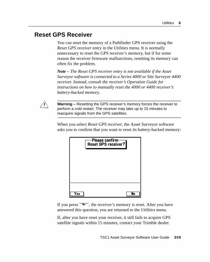
Utilities 6
6.4 Reset GPS ReceiverYou can reset the memory of a Pathfinder GPS receiver using theReset GPS receiver entry in the Utilities menu. It is normallyunnecessary to reset the GPS receiver’s memory, but if for somereason the receiver firmware malfunctions, resetting its memory canoften fix the problem.
Note – The Reset GPS receiver entry is not available if the AssetSurveyor software is connected to a Series 4000 or Site Surveyor 4400receiver. Instead, consult the receiver’s Operation Guide forinstructions on how to manually reset the 4000 or 4400 receiver’sbattery-backed memory.
C Warning – Resetting the GPS receiver’s memory forces the receiver toperform a cold restart. The receiver may take up to 15 minutes toreacquire signals from the GPS satellites.
When you select Reset GPS receiver, the Asset Surveyor softwareasks you to confirm that you want to reset its battery-backed memory:
If you pressy, the receiver’s memory is reset. After you haveanswered this question, you are returned to the Utilities menu.
If, after you have reset your receiver, it still fails to acquire GPSsatellite signals within 15 minutes, contact your Trimble dealer.
TSC1 Asset Surveyor Software User Guide 309
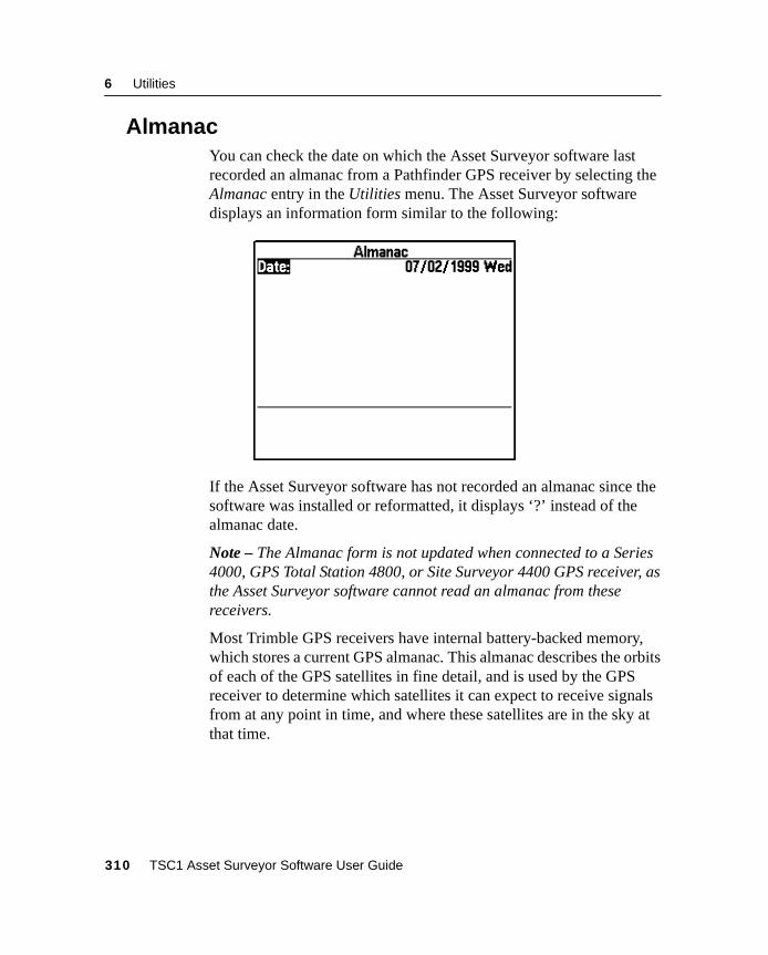
6 Utilities
6.5 AlmanacYou can check the date on which the Asset Surveyor software lastrecorded an almanac from a Pathfinder GPS receiver by selecting theAlmanac entry in the Utilities menu. The Asset Surveyor softwaredisplays an information form similar to the following:
If the Asset Surveyor software has not recorded an almanac since thesoftware was installed or reformatted, it displays ‘?’ instead of thealmanac date.
Note – The Almanac form is not updated when connected to a Series4000, GPS Total Station 4800, or Site Surveyor 4400 GPS receiver, asthe Asset Surveyor software cannot read an almanac from thesereceivers.
Most Trimble GPS receivers have internal battery-backed memory,which stores a current GPS almanac. This almanac describes the orbitsof each of the GPS satellites in fine detail, and is used by the GPSreceiver to determine which satellites it can expect to receive signalsfrom at any point in time, and where these satellites are in the sky atthat time.
310 TSC1 Asset Surveyor Software User Guide
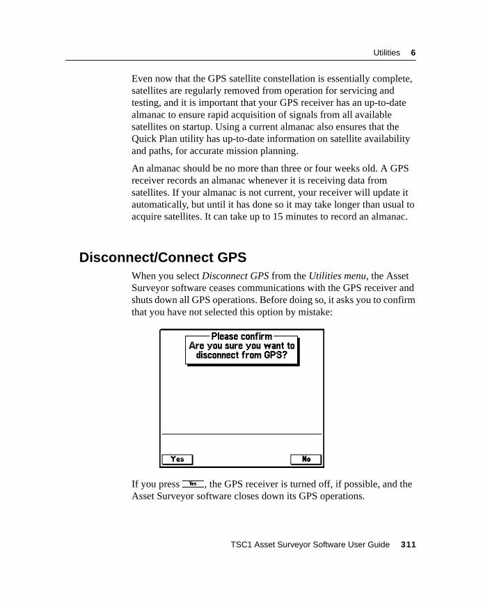
Utilities 6
Even now that the GPS satellite constellation is essentially complete,satellites are regularly removed from operation for servicing andtesting, and it is important that your GPS receiver has an up-to-datealmanac to ensure rapid acquisition of signals from all availablesatellites on startup. Using a current almanac also ensures that theQuick Plan utility has up-to-date information on satellite availabilityand paths, for accurate mission planning.
An almanac should be no more than three or four weeks old. A GPSreceiver records an almanac whenever it is receiving data fromsatellites. If your almanac is not current, your receiver will update itautomatically, but until it has done so it may take longer than usual toacquire satellites. It can take up to 15 minutes to record an almanac.
6.6 Disconnect/Connect GPSWhen you select Disconnect GPS from the Utilities menu, the AssetSurveyor software ceases communications with the GPS receiver andshuts down all GPS operations. Before doing so, it asks you to confirmthat you have not selected this option by mistake:
If you pressy, the GPS receiver is turned off, if possible, and theAsset Surveyor software closes down its GPS operations.
TSC1 Asset Surveyor Software User Guide 311
6 Utilities
Normally, you do not need to disconnect (deactivate) the GPSreceiver; you can just turn the TSC1 datalogger off when you finishusing it. If you want to use the Asset Surveyor software for a whilewithout needing GPS, and want to preserve the GPS receiver’sbatteries, you may choose to deactivate the receiver. You can useeither port for both file transfer and GPS connection, so it is notnecessary to physically disconnect the GPS cable before commencingfile transfer. However, you must disconnect GPS before file transfer isinitiated, as the Asset Surveyor software does not allow thesefunctions to be performed simultaneously.
When GPS is disconnected, the Disconnect GPS entry changes toConnect GPS, letting you re-activate GPS from the Utilities menu.
B Tip – You can also reactivate GPS by entering one of the GPS-relatedentries in the Main menu (Receiver status or Satellite information), or byopening a base station file, either of which automatically prompts theAsset Surveyor software to attempt to connect with the GPS receiver.
Note – When the Asset Surveyor software deactivates and turns off aSeries 4000 or Site Surveyor 4400 GPS receiver, it cannot turn thereceiver back on remotely. You must turn the Series 4000 or SiteSurveyor 4400 receiver on by pressing the [POWER] button on thereceiver’s front panel, before the Asset Surveyor software can re-establish communications with the receiver.
312 TSC1 Asset Surveyor Software User Guide
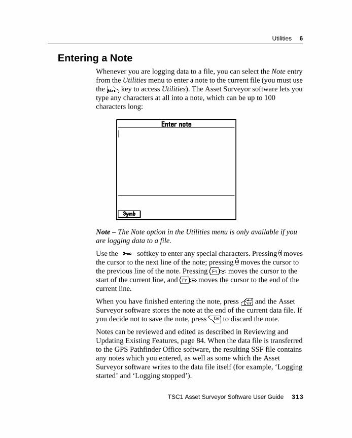
Utilities 6
6.7 Entering a NoteWhenever you are logging data to a file, you can select the Note entryfrom the Utilities menu to enter a note to the current file (you must usetheM key to access Utilities). The Asset Surveyor software lets youtype any characters at all into a note, which can be up to 100characters long:
Note – The Note option in the Utilities menu is only available if youare logging data to a file.
Use theV softkey to enter any special characters. Pressing )movesthe cursor to the next line of the note; pressing _ moves the cursor tothe previous line of the note. Pressing[* moves the cursor to thestart of the current line, and[( moves the cursor to the end of thecurrent line.
When you have finished entering the note, press\ and the AssetSurveyor software stores the note at the end of the current data file. Ifyou decide not to save the note, press= to discard the note.
Notes can be reviewed and edited as described in Reviewing andUpdating Existing Features, page 84. When the data file is transferredto the GPS Pathfinder Office software, the resulting SSF file containsany notes which you entered, as well as some which the AssetSurveyor software writes to the data file itself (for example, ‘Loggingstarted’ and ‘Logging stopped’).
TSC1 Asset Surveyor Software User Guide 313

6 Utilities
314 TSC1 Asset Surveyor Software User Guide
C H A P T E R
7
7 NavigationIn this chapter:
■ Introduction
■ Graphical navigation modes
■ Text-based navigation
■ Navigation and waypoints
7 Navigation
7.1 IntroductionYou can use the Asset Surveyor software together with a Trimble GPSreceiver to determine and record your current position. You can alsonavigate to a position of interest (the Target). The Target can be:
• a position that you have keyed in coordinates for
• a position that you have chosen from the map
• a waypoint that has been transferred from the GPS PathfinderOffice software
• a feature created in the Asset Surveyor software
• a feature transferred from the GPS Pathfinder Office softwareor your GIS
You can also navigate from a position (the Start). Like the Target, theStart can be any feature, waypoint, or position.
Navigation is traditionally associated with ensuring that you follow aprescribed course when traveling to your destination. You can also usenavigation to visit features that have been previously mapped, and toidentify a specific feature that may require maintenance.
As with other Trimble products, the Asset Surveyor softwaremaintains a list of waypoints (positions that you can name for futurereference and for navigating to or from). You can also navigate to andfrom features in a data file.
Even if you do not want to navigate to a particular point, you can usethe Navigation module to view information such as your currentspeed, heading, or (atomic accuracy) GPS time.
Note – If you are using an RTK capable receiver (such as a Series4000, 4400, 4700, or 4800 receiver) there will be a slight delay whilepositions are corrected. Try to avoid large changes of direction, orwait until the navigation display is updated before you changedirection again.
316 TSC1 Asset Surveyor Software User Guide
Navigation 7
C Warning – Do not rely on GPS as your primary source of navigation whenyou require greater accuracy than your system is currently providing, orwhen significant damage to property or personal safety could result fromthe effects of GPS inaccuracies.
7.2 Graphical Navigation ModesThe Asset Surveyor software provides two different navigationmodes: Direction Dial and Road. These modes let you navigate to aTarget using two different graphical styles to display the navigationinformation.
Press@ to switch between the navigation modes. Whenever youenter the Navigation module (by selecting Navigation from the Mainmenu), the Asset Surveyor software displays the navigation mode andconfigurations you were last using. When you first use the AssetSurveyor software to navigate, the default mode is the Direction Dial.
TSC1 Asset Surveyor Software User Guide 317
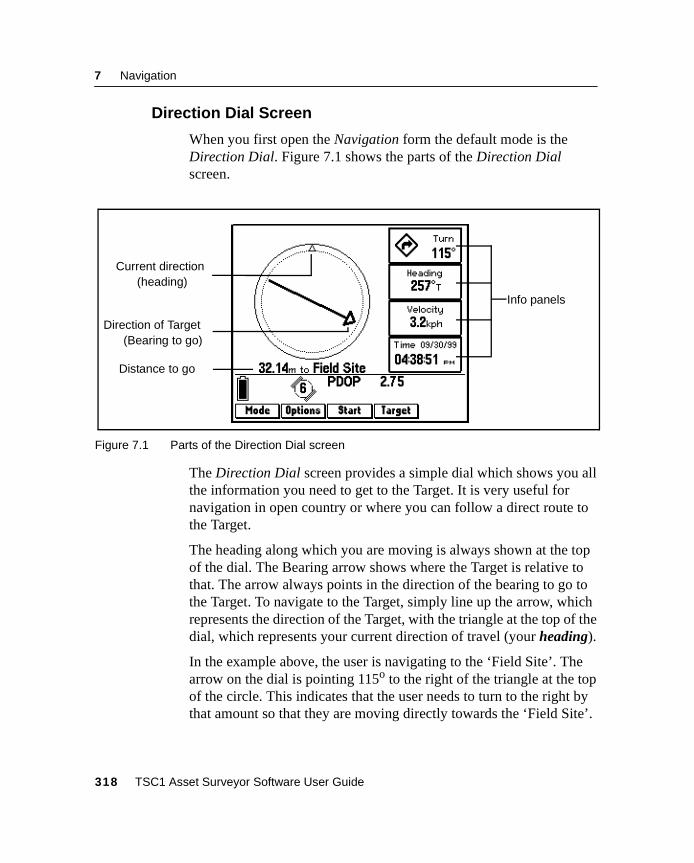
7 Navigation
7.2.1 Direction Dial Screen
When you first open the Navigation form the default mode is theDirection Dial. Figure 7.1 shows the parts of the Direction Dialscreen.
Figure 7.1 Parts of the Direction Dial screen
The Direction Dial screen provides a simple dial which shows you allthe information you need to get to the Target. It is very useful fornavigation in open country or where you can follow a direct route tothe Target.
The heading along which you are moving is always shown at the topof the dial. The Bearing arrow shows where the Target is relative tothat. The arrow always points in the direction of the bearing to go tothe Target. To navigate to the Target, simply line up the arrow, whichrepresents the direction of the Target, with the triangle at the top of thedial, which represents your current direction of travel (your heading).
In the example above, the user is navigating to the ‘Field Site’. Thearrow on the dial is pointing 115o to the right of the triangle at the topof the circle. This indicates that the user needs to turn to the right bythat amount so that they are moving directly towards the ‘Field Site’.
Info panels
Distance to go
Current direction
Direction of Target
(heading)
(Bearing to go)
318 TSC1 Asset Surveyor Software User Guide
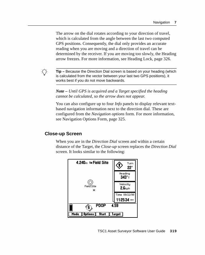
Navigation 7
The arrow on the dial rotates according to your direction of travel,which is calculated from the angle between the last two computedGPS positions. Consequently, the dial only provides an accuratereading when you are moving and a direction of travel can bedetermined by the receiver. If you are moving too slowly, the Headingarrow freezes. For more information, see Heading Lock, page 326.
B Tip – Because the Direction Dial screen is based on your heading (whichis calculated from the vector between your last two GPS positions), itworks best if you do not move backwards.
Note – Until GPS is acquired and a Target specified the headingcannot be calculated, so the arrow does not appear.
You can also configure up to four Info panels to display relevant text-based navigation information next to the direction dial. These areconfigured from the Navigation options form. For more information,see Navigation Options Form, page 325.
7.2.2 Close-up Screen
When you are in the Direction Dial screen and within a certaindistance of the Target, the Close-up screen replaces the Direction Dialscreen. It looks similar to the following:
TSC1 Asset Surveyor Software User Guide 319
7 Navigation
The Close-up screen consists of a bull’s-eye ring representing theTarget, and a cross representing the current GPS position. Forprecision navigation right up to the Target, move so that the GPSposition cross is in the center of the bull’s-eye.
Note – The top of the Close-up screen is relative to the direction oftravel (heading) when you entered the Close-up screen. The heading isnot updated on the Close-up screen, so the screen does not move if youchange the direction you are facing while using it.
B Tip – Because the Close-up screen does not update your heading, itworks best if you maintain your original direction of travel and if necessarymove sideways or backwards rather than turning.
Note – Due to the heading not being updated on the Close-up screen,all Info panels that depend on the heading are automatically locked aswell. For more information, see Heading Lock, page 326.
Close-up range
The close-up range value controls the distance from the Target atwhich the Direction Dial screen switches to the Close-up screen. Youcan configure the close-up range value to control the distance at whichthe Close-up screen appears, or to disable it.
The close-up range also determines the scale that is represented on theClose-up screen. The distance from the edge of the screen to the centerrepresents the close-up range distance.
B Tip – If you are zoomed in to a scale that is too close for the GPSaccuracy you currently have, the GPS cross appears to leap around thescreen. To minimize this effect, select a larger close-up range.
Configure the close-up range from the Navigation options form. Formore information, see Navigation Options Form, page 325.
320 TSC1 Asset Surveyor Software User Guide
Navigation 7
Proximity alarm
When you reach the close-up range to the Target, a proximity alarmsounds. This alarm sounds even if the Direction Dial screen is notopen or visible, so that you always have an audible warning that youare approaching the Target.
The proximity alarm sounds whenever you move into close-up range,but it does not sound when you move out of close-up range.
B Tip – You cannot disable the proximity alarm, but you can prevent it fromsounding, either by turning all sounds off (under Configuration / Hardware(TSC1)), or by setting the close-up range to zero.
Close-up style
The close-up style can be set to either Target-centered orGPS-centered. It controls which is the fixed reference point in thecenter of the Close-up screen. For the target-centered style, the Targetbull’s eye is fixed in the center of the screen and the GPS cross movesaround it as your position changes. For GPS-centered navigation theopposite occurs; the GPS cross is fixed in the center of the screen andthe bull’s-eye effectively moves around it.
Configure the close-up style from the Navigation options form. Formore information, see Navigation Options Form, page 325.
TSC1 Asset Surveyor Software User Guide 321
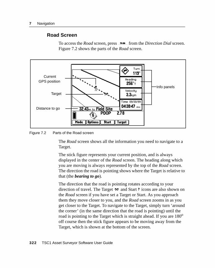
7 Navigation
7.2.3 Road Screen
To access the Road screen, press@ from the Direction Dial screen.Figure 7.2 shows the parts of the Road screen.
Figure 7.2 Parts of the Road screen
The Road screen shows all the information you need to navigate to aTarget.
The stick figure represents your current position, and is alwaysdisplayed in the center of the Road screen. The heading along whichyou are moving is always represented by the top of the Road screen.The direction the road is pointing shows where the Target is relative tothat (the bearing to go).
The direction that the road is pointing rotates according to yourdirection of travel. The Target and Start icons are also shown onthe Road screen if you have set a Target or Start. As you approachthem they move closer to you, and the Road screen zooms in as youget closer to the Target. To navigate to the Target, simply turn ‘aroundthe corner’ (in the same direction that the road is pointing) until theroad is pointing to the Target which is straight ahead. If you are 180o
off course then the stick figure appears to be moving away from theTarget, which is shown at the bottom of the screen.
Info panels
Distance to go
Current
Target
GPS position
322 TSC1 Asset Surveyor Software User Guide
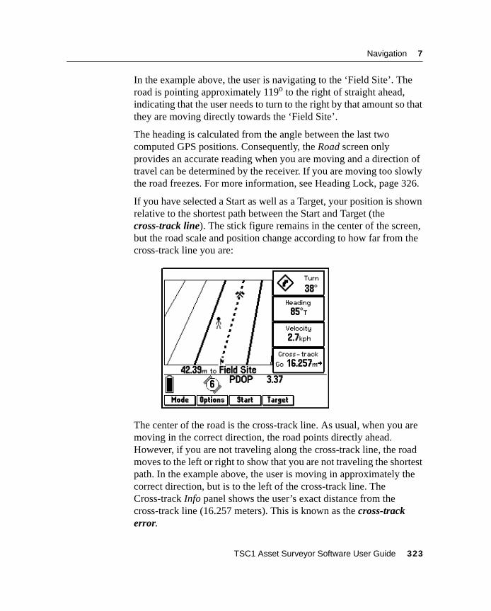
Navigation 7
In the example above, the user is navigating to the ‘Field Site’. Theroad is pointing approximately 119o to the right of straight ahead,indicating that the user needs to turn to the right by that amount so thatthey are moving directly towards the ‘Field Site’.
The heading is calculated from the angle between the last twocomputed GPS positions. Consequently, the Road screen onlyprovides an accurate reading when you are moving and a direction oftravel can be determined by the receiver. If you are moving too slowlythe road freezes. For more information, see Heading Lock, page 326.
If you have selected a Start as well as a Target, your position is shownrelative to the shortest path between the Start and Target (thecross-track line). The stick figure remains in the center of the screen,but the road scale and position change according to how far from thecross-track line you are:
The center of the road is the cross-track line. As usual, when you aremoving in the correct direction, the road points directly ahead.However, if you are not traveling along the cross-track line, the roadmoves to the left or right to show that you are not traveling the shortestpath. In the example above, the user is moving in approximately thecorrect direction, but is to the left of the cross-track line. TheCross-track Info panel shows the user’s exact distance from thecross-track line (16.257 meters). This is known as the cross-trackerror.
TSC1 Asset Surveyor Software User Guide 323
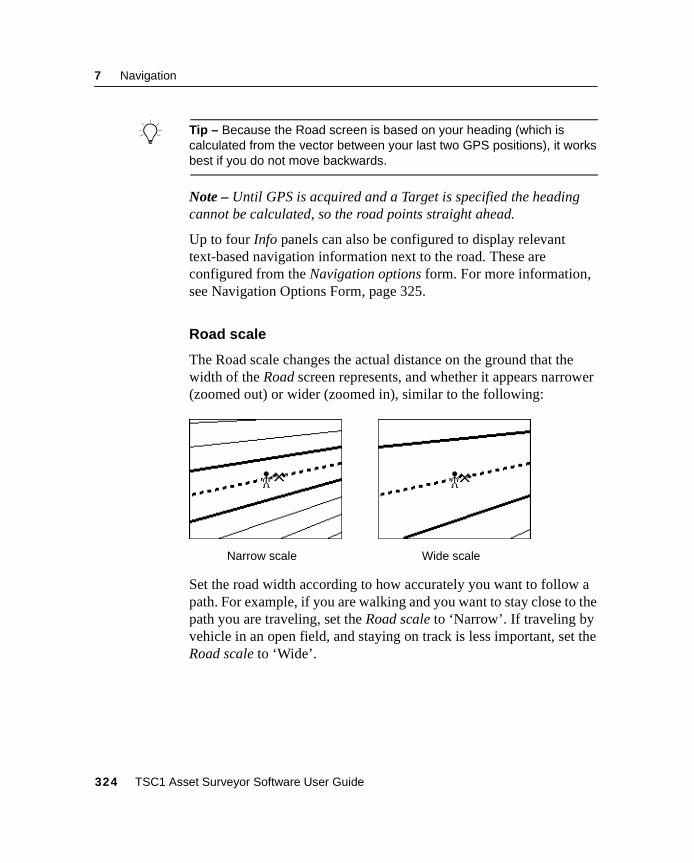
7 Navigation
B Tip – Because the Road screen is based on your heading (which iscalculated from the vector between your last two GPS positions), it worksbest if you do not move backwards.
Note – Until GPS is acquired and a Target is specified the headingcannot be calculated, so the road points straight ahead.
Up to four Info panels can also be configured to display relevanttext-based navigation information next to the road. These areconfigured from the Navigation options form. For more information,see Navigation Options Form, page 325.
Road scale
The Road scale changes the actual distance on the ground that thewidth of the Road screen represents, and whether it appears narrower(zoomed out) or wider (zoomed in), similar to the following:
Set the road width according to how accurately you want to follow apath. For example, if you are walking and you want to stay close to thepath you are traveling, set the Road scale to ‘Narrow’. If traveling byvehicle in an open field, and staying on track is less important, set theRoad scale to ‘Wide’.
Narrow scale Wide scale
324 TSC1 Asset Surveyor Software User Guide
Navigation 7
7.2.4 Navigation Options Form
To access the Navigation options form, press& from anynavigation screen. It contains options for configuring all navigationscreens, although it defaults to show the page for the mode you arecurrently in.
Direction Dial options
This set of options is for the Direction Dial screen. You do not have tobe in the Direction Dial screen to configure them.
Dial info panel fields – Configure which Info panels appear in the fourspaces on the Direction Dial screen.
Close-up range – Configure the distance from the Target at which theDirection Dial screen changes to the Close-up screen.
Close-up style – Configure the focal point of the Close-up screen.Select ‘Target-centered’ or ‘GPS-centered’.
Road options
This set of options is for the Road screen. You do not have to be in theRoad screen to configure them.
Road info panel fields – Configure which Info panels appear in thefour spaces on the Road screen.
Road scale – Configure the scale (width) that the Road screenrepresents.
TSC1 Asset Surveyor Software User Guide 325
7 Navigation
7.2.5 Map Navigation
You can also navigate to a Target using the Map module. For moreinformation, see Chapter 8, Map.
7.2.6 Old Navigation
When GPS position information is temporarily unavailable (forexample, when one or more satellites is obscured, or due to a highPDOP), the Asset Surveyor software still displays the most recentnavigation information. However, it flashes a message in the messagearea of the Navigation form to indicate that the displayed navigationinformation is old. The direction dial arrow and any Info panelsaffected flash. The Road screen freezes, but does not flash.
7.2.7 Heading Lock
The heading is calculated from the angle between the last twocomputed GPS positions. If you are stationary or moving very slowlythen any positional error causes the GPS position to wander aroundyour current location, resulting in false heading information.
To counteract this, the heading is locked below the preset Cutoffvelocity. When this happens the message Heading locked flashes in themessage area, alternating with Start moving. (If no heading has beencalculated since startup then the first message is replaced with Headingunavailable). The direction dial arrow, the Road screen, and any Infopanels affected freeze. These include Heading, Bearing, ETA, andTime to go. The Heading triangle on the Map screen also freezes. Tounlock the heading, start moving (faster than the Cutoff velocity).
Note – The cutoff velocity is preset at the factory and cannot beconfigured. When you are using autonomous GPS, the cutoff velocityis 0.65 meters/second (2.34 kilometers/hour). With differential GPSthe cutoff velocity is 0.35 meters/second (1.26 kilometers/hour).
Note – The heading is always locked when the Close-up screen isvisible.
326 TSC1 Asset Surveyor Software User Guide
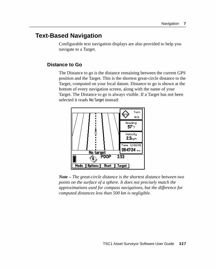
Navigation 7
7.3 Text-Based NavigationConfigurable text navigation displays are also provided to help younavigate to a Target.
7.3.1 Distance to Go
The Distance to go is the distance remaining between the current GPSposition and the Target. This is the shortest great-circle distance to theTarget, computed on your local datum. Distance to go is shown at thebottom of every navigation screen, along with the name of yourTarget. The Distance to go is always visible. If a Target has not beenselected it reads No Target instead:
Note – The great-circle distance is the shortest distance between twopoints on the surface of a sphere. It does not precisely match theapproximations used for compass navigations, but the difference forcomputed distances less than 500 km is negligible.
TSC1 Asset Surveyor Software User Guide 327
7 Navigation
7.3.2 Info Panels
Info panels are text display panels that you can configure. They appearon all navigation screens. You can display up to four Info panels oneach navigation screen. Pressing the@ softkey to switch betweenscreens changes the Info panels too, depending on the configuration ofthe screen you are switching to. You can configure up to eight Infopanels (four for each navigation mode).
Info panels are configured from the Navigation options form, whichyou can access by pressing& in the Navigation module or byselecting Navigation options from the Configuration menu.
For details on configuring Info panels, see Navigation Options Form,page 325.
The following Info panels are available:
• Turn: This panel shows the direction you need to turn to headtowards the Target, along with the size of the turn angle. Thearrow indicates whether you should veer to the left or to theright and approximately how big a turn is required. The numericvalue indicates the magnitude by which your course should vary(the difference between the bearing to the Target and the currentheading). As with the heading, this value is most useful if youare receiving real-time differential corrections or are travelingat a reasonable speed.
• Bearing to Go: This panel shows the compass bearing (angle)that you should follow in order to take the shortest path betweenthe current GPS position and the Target. The bearing to go isuseful if you are navigating in open country and can travel in adirect line to the Target. The bearing is displayed with a ‘T’ if itis relative to true north or an ‘M’ if it is relative to magneticnorth. If a Target has not been selected this field is null.
328 TSC1 Asset Surveyor Software User Guide
Navigation 7
• Heading: This panel shows your current direction of travel as acompass angle. The heading is the angle between the last twoGPS positions computed, and is therefore likely to be mostaccurate if you are receiving differential corrections. If you arestationary or moving very slowly, the velocity lock freezes theheading display until you start moving again. The units of thisfield also include a ‘T’ or ‘M’ to indicate whether the heading isrelative to true or magnetic north. The heading is displayedwhether or not you have chosen a Start or Target.
• Time: This panel shows the current time and date. The valueshows GPS time (atomic accuracy), with the local variationfrom GMT time applied from the Time and Date setting. Thisfield is displayed regardless of whether a Start or Target hasbeen selected.
• Time to Go: This panel displays the expected time to reach theTarget (if any). The time to go takes your current heading andvelocity into account. It shows a larger value if you are notheading directly toward the Target. This field is null if there isno Target selected.
• ETA: This panel displays the Estimated Time of Arrival (ETA)at the Target, based on your current heading and velocity. Itshows a larger value if you are not heading directly toward theTarget. If the arrival time is more than 24 hours in the future itdisplays >24 hr. This field is null if there is no Target selected.
• Velocity: This panel displays your two-dimensional velocity.The velocity is displayed whether or not you have chosen aStart or Target.
• Go N/E: This panel indicates the northerly and easterly distancecomponents of the bearing to go to the Target. It is given as twoCartesian distances, with one value representing the north/southdistance and one representing the east/west distance from thecurrent GPS position to the Target. This panel is very useful fornavigation around city blocks, or when you cannot travel in adirect line to the Target. If a Target has not been selected thisfield is null.
TSC1 Asset Surveyor Software User Guide 329
7 Navigation
• Cross-track: This panel shows the direction and distance to thecross-track line (XTE). This is an imaginary straight linelinking the Start and Target by the shortest route. It is useful ifyou need to navigate without deviating too far from the directpath to the Target. The direction of the cross-track line (left orright) is indicated by ← or → arrows. The numeric valueindicates the distance you should travel in that direction to getback on line. Unless both a Start and a Target have beenselected, this field is null.
• Altitude: This panel shows the current altitude. If you are using2D GPS then the altitude shown is the value entered in the 2Daltitude field. The Altitude reference used (HAE or MSL) is alsoshown. The altitude is displayed whether or not you havechosen a Start or Target.
• Go Up/Down: This panel shows the difference in altitudebetween the current altitude and the altitude of the Target, and isvery useful for 3D navigation. It tells you how far up or downyou need to go to be at the same altitude as the Target. If you areusing 2D GPS then the current altitude used is the value enteredin the 2D altitude field. This field is null if there is no Targetselected.
B Tip – You can change any of the above units or the style of display in theUnits and display configuration form. For more information, see Units andDisplay, page 250.
330 TSC1 Asset Surveyor Software User Guide
Navigation 7
7.4 Navigation and WaypointsThis section describes how to select waypoints and features fornavigation purposes. For a detailed description of how to create andmanage waypoints, see Waypoints, page 300.
7.4.1 Selecting the Start and Target
The Target is a position you want to navigate to. Once you select aTarget, the Asset Surveyor software can provide navigationinformation such as the distance to the Target and the direction youneed to travel in.
Using a Start lets you plot and measure a direct path from one locationto another. When you select a Start you can monitor the cross-trackerror (XTE) in the Cross-track Info panel, or in the Road screen, toensure you stay on the shortest path from your starting location to theTarget. To navigate to a Target you can either navigate from yourcurrent position, or navigate from a Start. You do not have to select aStart for navigation.
Select the Target for navigation by pressingG and the Start bypressingT . When you press eitherG orT, the AssetSurveyor software opens the menu of current waypoints on the TSC1datalogger, along with all features in the currently open data file. Youcan select any feature or waypoint from the menu, or you can clear theStart or Target by selecting ‘None’.
When you first use the Asset Surveyor software to navigate, no Startand Target are selected. Once you have selected a Start and/or aTarget, these remain selected for subsequent navigation sessions, untilyou change them. If your Start or Target is a feature, its position willstill be remembered if you close the file, but if you open another datafile, it will be reset to ‘None’. A Start or Target that is a waypoint isnot affected by file operations. Once a Start or Target has been set itapplies to the whole system, including the Map module and Reviewdata list.
TSC1 Asset Surveyor Software User Guide 331
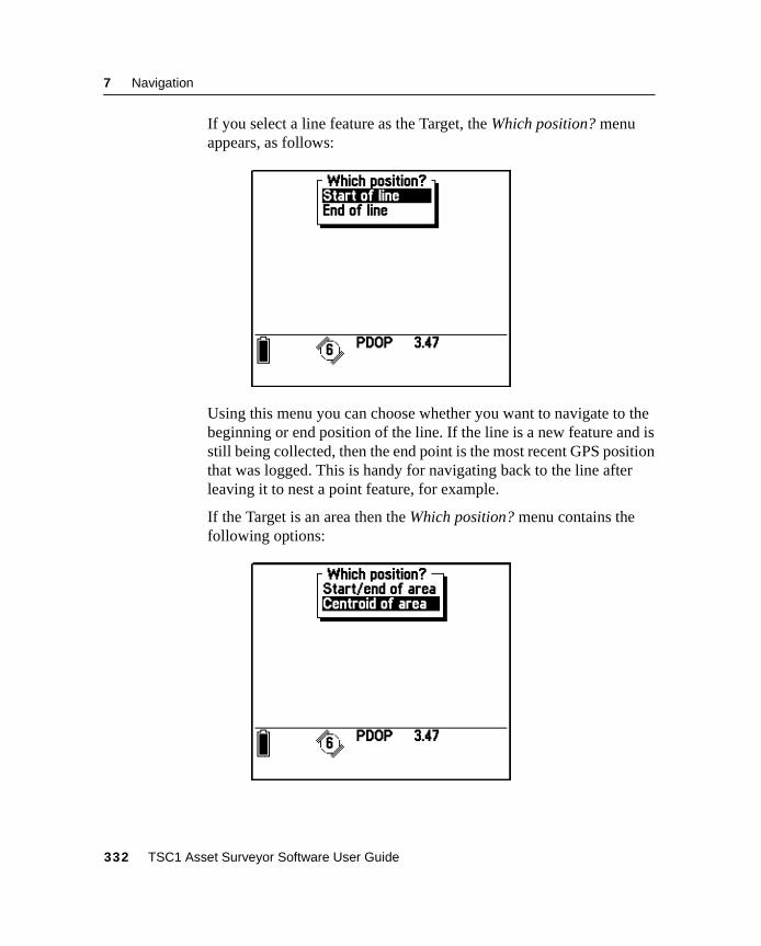
7 Navigation
If you select a line feature as the Target, the Which position? menuappears, as follows:
Using this menu you can choose whether you want to navigate to thebeginning or end position of the line. If the line is a new feature and isstill being collected, then the end point is the most recent GPS positionthat was logged. This is handy for navigating back to the line afterleaving it to nest a point feature, for example.
If the Target is an area then the Which position? menu contains thefollowing options:
332 TSC1 Asset Surveyor Software User Guide
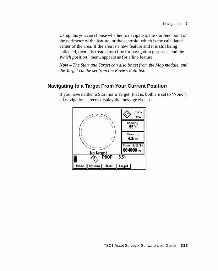
Navigation 7
Using this you can choose whether to navigate to the start/end point onthe perimeter of the feature, or the centroid, which is the calculatedcenter of the area. If the area is a new feature and it is still beingcollected, then it is treated as a line for navigation purposes, and theWhich position? menu appears as for a line feature.
Note – The Start and Target can also be set from the Map module, andthe Target can be set from the Review data list.
7.4.2 Navigating to a Target From Your Current Position
If you have neither a Start nor a Target (that is, both are set to ‘None’),all navigation screens display the message No target:
TSC1 Asset Surveyor Software User Guide 333
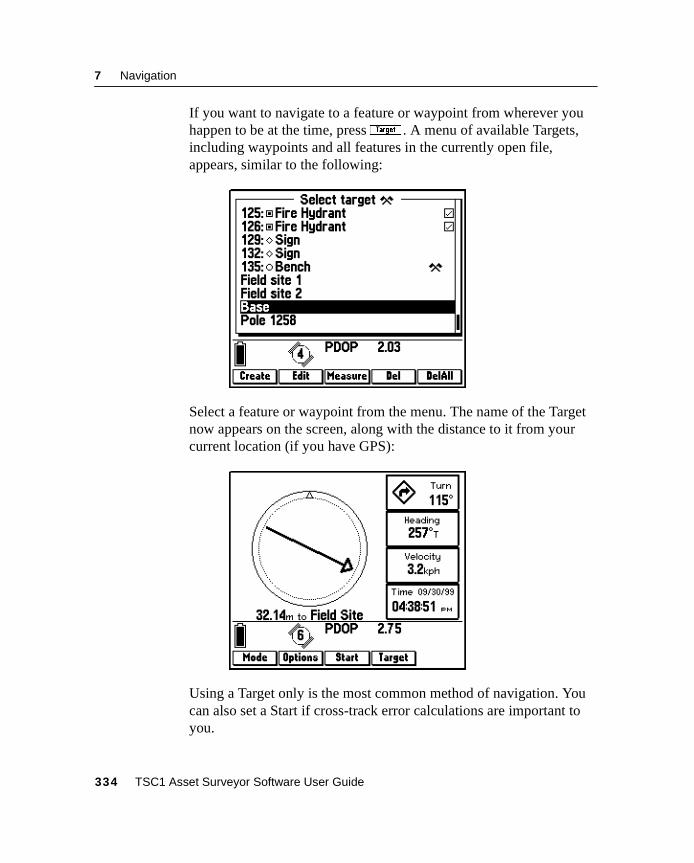
7 Navigation
If you want to navigate to a feature or waypoint from wherever youhappen to be at the time, pressG . A menu of available Targets,including waypoints and all features in the currently open file,appears, similar to the following:
Select a feature or waypoint from the menu. The name of the Targetnow appears on the screen, along with the distance to it from yourcurrent location (if you have GPS):
Using a Target only is the most common method of navigation. Youcan also set a Start if cross-track error calculations are important toyou.
334 TSC1 Asset Surveyor Software User Guide
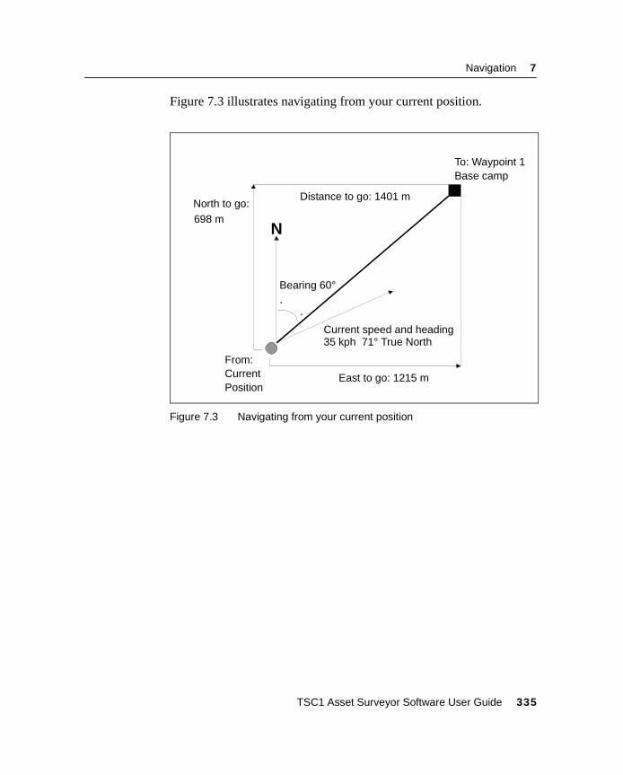
Navigation 7
Figure 7.3 illustrates navigating from your current position.
Figure 7.3 Navigating from your current position
N
North to go:698 m
Bearing 60°
Distance to go: 1401 m
Current speed and heading35 kph 71° True North
From:CurrentPosition
East to go: 1215 m
To: Waypoint 1Base camp
TSC1 Asset Surveyor Software User Guide 335
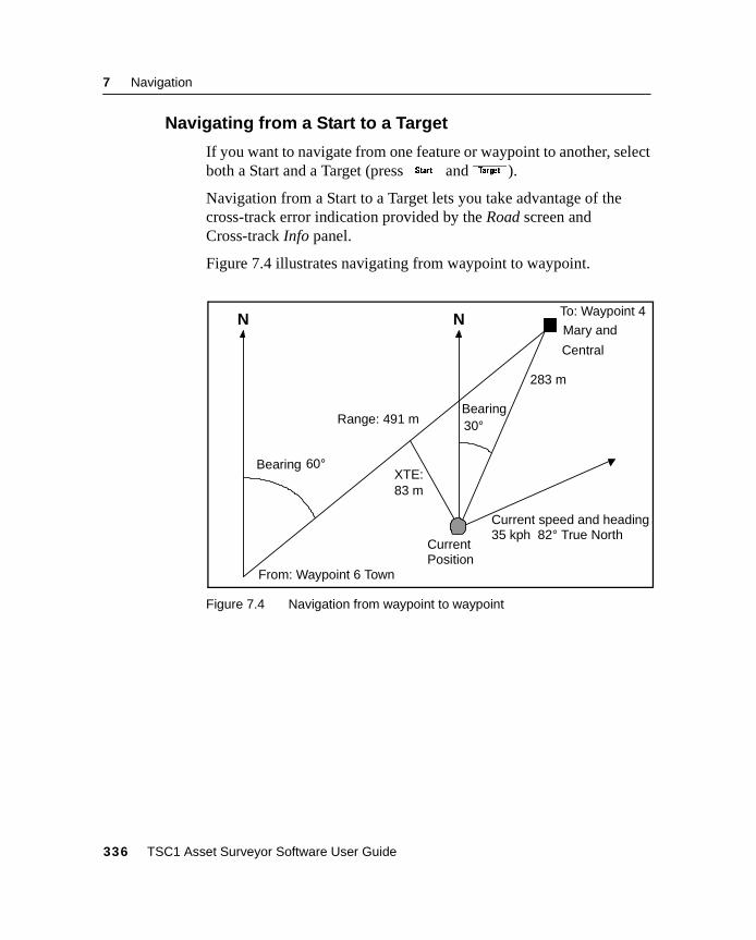
7 Navigation
7.4.3 Navigating from a Start to a Target
If you want to navigate from one feature or waypoint to another, selectboth a Start and a Target (pressT andG).
Navigation from a Start to a Target lets you take advantage of thecross-track error indication provided by the Road screen andCross-track Info panel.
Figure 7.4 illustrates navigating from waypoint to waypoint.
Figure 7.4 Navigation from waypoint to waypoint
NN
Current speed and heading35 kph 82° True North
To: Waypoint 4
Mary and
Bearing30°
283 m
CurrentPosition
XTE:83 m
Range: 491 m
Bearing 60°
From: Waypoint 6 Town
Central
336 TSC1 Asset Surveyor Software User Guide
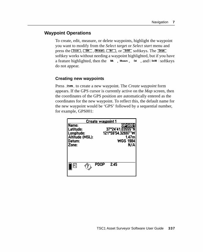
Navigation 7
7.4.4 Waypoint Operations
To create, edit, measure, or delete waypoints, highlight the waypointyou want to modify from the Select target or Select start menu andpress theB ,e ,x ,d , orD softkeys. TheBsoftkey works without needing a waypoint highlighted, but if you havea feature highlighted, then thee ,x ,d , andD softkeysdo not appear.
Creating new waypoints
PressB to create a new waypoint. The Create waypoint formappears. If the GPS cursor is currently active on the Map screen, thenthe coordinates of the GPS position are automatically entered as thecoordinates for the new waypoint. To reflect this, the default name forthe new waypoint would be ‘GPS’ followed by a sequential number,for example, GPS001:
TSC1 Asset Surveyor Software User Guide 337
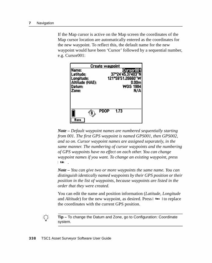
7 Navigation
If the Map cursor is active on the Map screen the coordinates of theMap cursor location are automatically entered as the coordinates forthe new waypoint. To reflect this, the default name for the newwaypoint would have been ‘Cursor’ followed by a sequential number,e.g. Cursor001:
Note – Default waypoint names are numbered sequentially startingfrom 001. The first GPS waypoint is named GPS001, then GPS002,and so on. Cursor waypoint names are assigned separately, in thesame manner. The numbering of cursor waypoints and the numberingof GPS waypoints have no effect on each other. You can changewaypoint names if you want. To change an existing waypoint, presse .
Note – You can give two or more waypoints the same name. You candistinguish identically named waypoints by their GPS position or theirposition in the list of waypoints, because waypoints are listed in theorder that they were created.
You can edit the name and position information (Latitude, Longitudeand Altitude) for the new waypoint, as desired. Pressh to replacethe coordinates with the current GPS position.
B Tip – To change the Datum and Zone, go to Configuration: Coordinatesystem.
338 TSC1 Asset Surveyor Software User Guide
Navigation 7
Press\ to save the new waypoint. This takes you back to the Selecttarget menu. The name of the newly created waypoint is nowhighlighted in the list.
If you want to set the new waypoint as the Target, press\ ;otherwise press=. Pressing= exits the Select target form withoutselecting a new Target. However, the new waypoint has still beencreated in the system.
For more information, see Chapter 6, Utilities.
Edit
To edit the name, coordinates, or altitude details of an existingwaypoint, highlight the waypoint on the Select start or Select targetmenu and presse . For more information, see Chapter 6, Utilities.
Note – Thee softkey does not appear if the highlighted item on themenu is a feature.
Measure
To calculate the distance between any two waypoints, highlight thefirst waypoint on the Select start or Select target menu and pressx . In the Measure form, choose the other waypoint to measure to.The measuring function calculates the distance between the waypointsbased on their coordinates, so does not require GPS.
For more information, see Chapter 6, Utilities.
Note – Thex softkey does not appear if the highlighted item on themenu is a feature.
TSC1 Asset Surveyor Software User Guide 339
7 Navigation
Delete
To delete an existing waypoint, highlight the waypoint on the Selectstart or Select target menu and pressd . For more information, seeChapter 6, Utilities.
Note – Thed softkey does not appear if the highlighted item on themenu is a feature.
Delete All
To delete all existing waypoints, highlight a waypoint on the Selectstart or Select target menu and pressD . For more information, seeChapter 6, Utilities.
Note – TheD softkey does not appear if the highlighted item on themenu is a feature.
340 TSC1 Asset Surveyor Software User Guide
C H A P T E R
8
8 MapIn this chapter:
■ Introduction
■ Map display
■ The map cursor
■ Selecting features for update
■ Zoom operations
■ Map display options
■ Background file display
■ Text mode
■ Filtering
■ Navigation in the Map screen
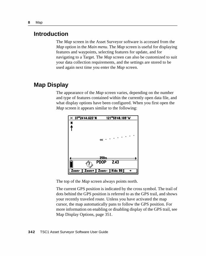
8 Map
8.1 IntroductionThe Map screen in the Asset Surveyor software is accessed from theMap option in the Main menu. The Map screen is useful for displayingfeatures and waypoints, selecting features for update, and fornavigating to a Target. The Map screen can also be customized to suityour data collection requirements, and the settings are stored to beused again next time you enter the Map screen.
8.2 Map DisplayThe appearance of the Map screen varies, depending on the numberand type of features contained within the currently open data file, andwhat display options have been configured. When you first open theMap screen it appears similar to the following:
The top of the Map screen always points north.
The current GPS position is indicated by the cross symbol. The trail ofdots behind the GPS position is referred to as the GPS trail, and showsyour recently traveled route. Unless you have activated the mapcursor, the map automatically pans to follow the GPS position. Formore information on enabling or disabling display of the GPS trail, seeMap Display Options, page 351.
342 TSC1 Asset Surveyor Software User Guide
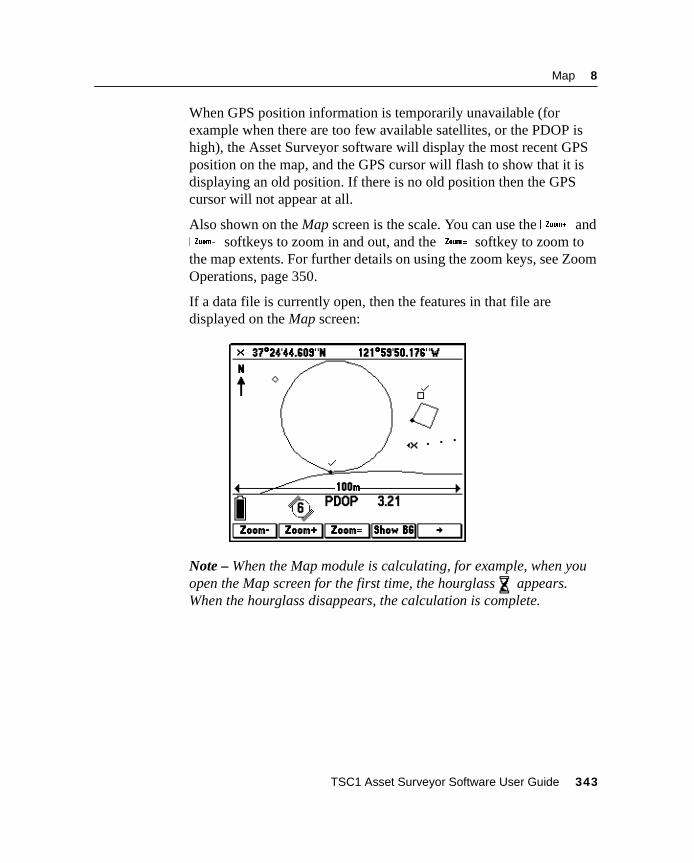
Map 8
When GPS position information is temporarily unavailable (forexample when there are too few available satellites, or the PDOP ishigh), the Asset Surveyor software will display the most recent GPSposition on the map, and the GPS cursor will flash to show that it isdisplaying an old position. If there is no old position then the GPScursor will not appear at all.
Also shown on the Map screen is the scale. You can use the+ and_ softkeys to zoom in and out, and the= softkey to zoom tothe map extents. For further details on using the zoom keys, see ZoomOperations, page 350.
If a data file is currently open, then the features in that file aredisplayed on the Map screen:
Note – When the Map module is calculating, for example, when youopen the Map screen for the first time, the hourglass appears.When the hourglass disappears, the calculation is complete.
TSC1 Asset Surveyor Software User Guide 343
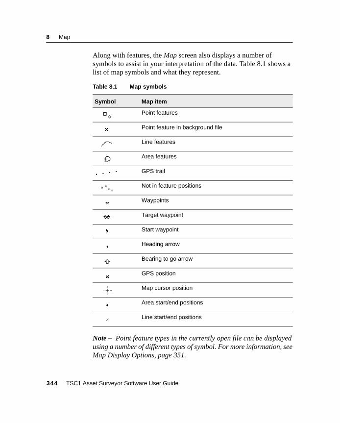
8 Map
Along with features, the Map screen also displays a number ofsymbols to assist in your interpretation of the data. Table 8.1 shows alist of map symbols and what they represent.
Note – Point feature types in the currently open file can be displayedusing a number of different types of symbol. For more information, seeMap Display Options, page 351.
Table 8.1 Map symbols
Symbol Map item
Point features
Point feature in background file
Line features
Area features
GPS trail
Not in feature positions
Waypoints
Target waypoint
Start waypoint
Heading arrow
Bearing to go arrow
GPS position
Map cursor position
Area start/end positions
Line start/end positions
344 TSC1 Asset Surveyor Software User Guide
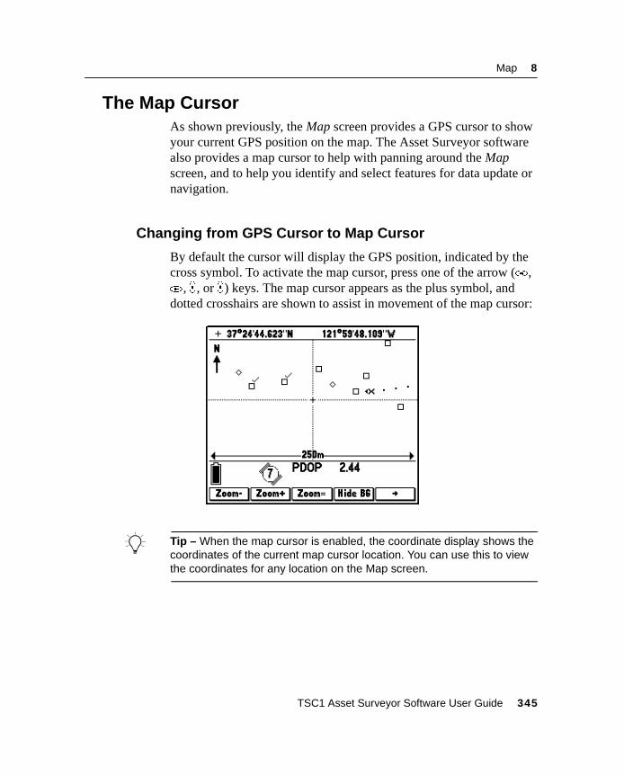
Map 8
8.3 The Map CursorAs shown previously, the Map screen provides a GPS cursor to showyour current GPS position on the map. The Asset Surveyor softwarealso provides a map cursor to help with panning around the Mapscreen, and to help you identify and select features for data update ornavigation.
8.3.1 Changing from GPS Cursor to Map Cursor
By default the cursor will display the GPS position, indicated by thecross symbol. To activate the map cursor, press one of the arrow (* ,( , ) , or _) keys. The map cursor appears as the plus symbol, anddotted crosshairs are shown to assist in movement of the map cursor:
B Tip – When the map cursor is enabled, the coordinate display shows thecoordinates of the current map cursor location. You can use this to viewthe coordinates for any location on the Map screen.
TSC1 Asset Surveyor Software User Guide 345
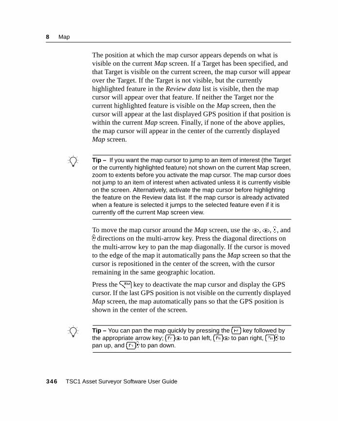
8 Map
The position at which the map cursor appears depends on what isvisible on the current Map screen. If a Target has been specified, andthat Target is visible on the current screen, the map cursor will appearover the Target. If the Target is not visible, but the currentlyhighlighted feature in the Review data list is visible, then the mapcursor will appear over that feature. If neither the Target nor thecurrent highlighted feature is visible on the Map screen, then thecursor will appear at the last displayed GPS position if that position iswithin the current Map screen. Finally, if none of the above applies,the map cursor will appear in the center of the currently displayedMap screen.
B Tip – If you want the map cursor to jump to an item of interest (the Targetor the currently highlighted feature) not shown on the current Map screen,zoom to extents before you activate the map cursor. The map cursor doesnot jump to an item of interest when activated unless it is currently visibleon the screen. Alternatively, activate the map cursor before highlightingthe feature on the Review data list. If the map cursor is already activatedwhen a feature is selected it jumps to the selected feature even if it iscurrently off the current Map screen view.
To move the map cursor around the Map screen, use the* ,( , ) , and_ directions on the multi-arrow key. Press the diagonal directions onthe multi-arrow key to pan the map diagonally. If the cursor is movedto the edge of the map it automatically pans the Map screen so that thecursor is repositioned in the center of the screen, with the cursorremaining in the same geographic location.
Press the= key to deactivate the map cursor and display the GPScursor. If the last GPS position is not visible on the currently displayedMap screen, the map automatically pans so that the GPS position isshown in the center of the screen.
B Tip – You can pan the map quickly by pressing the[ key followed bythe appropriate arrow key;[* to pan left,[( to pan right,[_ topan up, and[) to pan down.
346 TSC1 Asset Surveyor Software User Guide
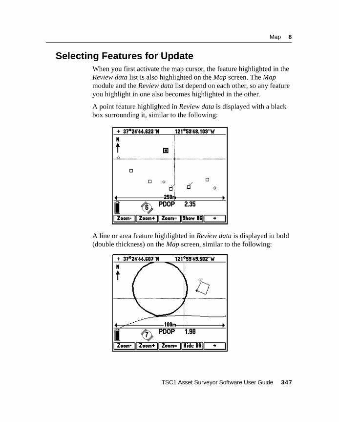
Map 8
8.4 Selecting Features for UpdateWhen you first activate the map cursor, the feature highlighted in theReview data list is also highlighted on the Map screen. The Mapmodule and the Review data list depend on each other, so any featureyou highlight in one also becomes highlighted in the other.
A point feature highlighted in Review data is displayed with a blackbox surrounding it, similar to the following:
A line or area feature highlighted in Review data is displayed in bold(double thickness) on the Map screen, similar to the following:
TSC1 Asset Surveyor Software User Guide 347
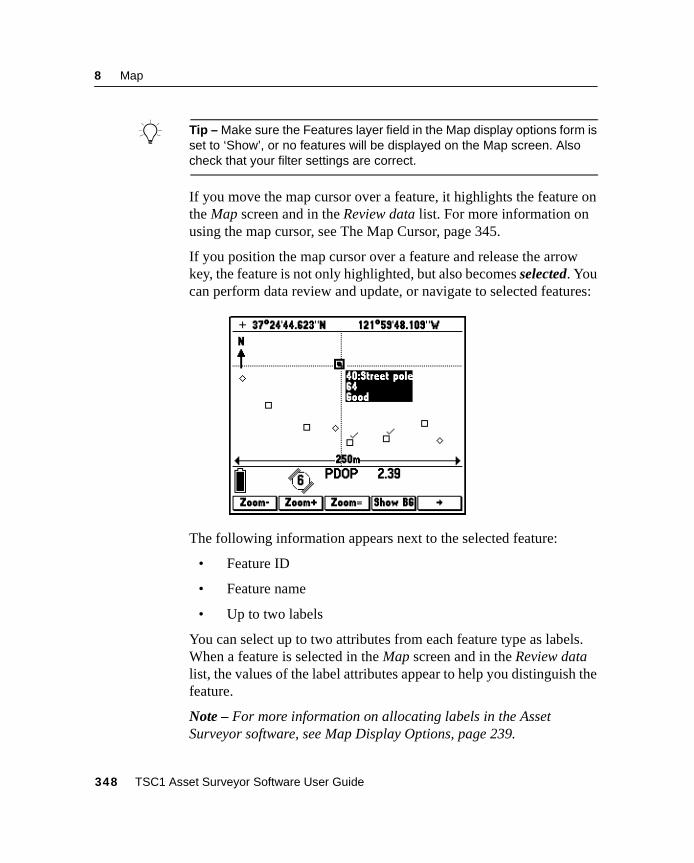
8 Map
B Tip – Make sure the Features layer field in the Map display options form isset to ‘Show’, or no features will be displayed on the Map screen. Alsocheck that your filter settings are correct.
If you move the map cursor over a feature, it highlights the feature onthe Map screen and in the Review data list. For more information onusing the map cursor, see The Map Cursor, page 345.
If you position the map cursor over a feature and release the arrowkey, the feature is not only highlighted, but also becomes selected. Youcan perform data review and update, or navigate to selected features:
The following information appears next to the selected feature:
• Feature ID
• Feature name
• Up to two labels
You can select up to two attributes from each feature type as labels.When a feature is selected in the Map screen and in the Review datalist, the values of the label attributes appear to help you distinguish thefeature.
Note – For more information on allocating labels in the AssetSurveyor software, see Map Display Options, page 239.
348 TSC1 Asset Surveyor Software User Guide
Map 8
On either the Map screen or the Review data list, you can press the\ key to open the currently selected feature for review or dataupdate. The attribute form for the selected feature opens, allowing youto review and/or update attribute or position information for thatfeature. For more information, see Data Review and Update, page 80.
When you move the map cursor off a feature, that feature remainshighlighted, until you move the cursor over a new feature or you selecta new feature from the Review data list. To be able to open a featurefor update, the map cursor must remain positioned over that feature, sothat it is both highlighted and selected.
Note – You cannot open a feature for data update if it is onlyhighlighted; it must be selected with the map cursor first. Howeveryou can set either a highlighted or selected feature as the Start orTarget for navigation by pressing theT orG softkey.
B Tip – Filtering hides or shows certain types of information on the Mapscreen. You can use this to show only the features you are interested in,based on the filtering parameters. Sorting will change the order of thefeature list. It will also change the order of the feature ID numbers,because each ID number is linked to only one feature until the file istransferred to the GPS Pathfinder Office software. You can use this to listthe features in the order that you want to visit them, based on the sortparameters. For more information, see Data Review and Update,page 80.
TSC1 Asset Surveyor Software User Guide 349
8 Map
8.5 Zoom OperationsIn the Asset Surveyor software, three softkeys control the scale atwhich the Map screen is drawn. The scale is shown at the bottom ofthe Map screen. Zoom scales range from 25 cm to 2000 km.
• Use the+ softkey to zoom in to a smaller scale.
• Use the_ softkey to zoom out to a larger scale.
• Press the= softkey to Zoom to the map extents. Mapextents is the scale at which all visible items, includingwaypoints and features in foreground and background files, canbe displayed on the current Map screen.
By default the Map screen is displayed at a scale of 250 m with thescreen centered on the GPS cursor, or at the extents of the open datafile if GPS is not available.
When there is no open data file, or other foreground data such aswaypoints, the Map screen defaults to a scale of 250 m, centered onthe Initial position.
350 TSC1 Asset Surveyor Software User Guide
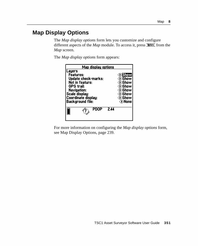
Map 8
8.6 Map Display OptionsThe Map display options form lets you customize and configuredifferent aspects of the Map module. To access it, press& from theMap screen.
The Map display options form appears:
For more information on configuring the Map display options form,see Map Display Options, page 239.
TSC1 Asset Surveyor Software User Guide 351
8 Map
8.7 Background File DisplayThe Asset Surveyor software provides the capability to display datafiles as a background file in the Map screen. When a file is specified asthe background file its features are visible but they are read-only andcannot be selected, updated, or deleted.
Any file specified as the background file is displayed on the Mapscreen by default. The background file can be temporarily hidden bypressing the2 softkey which turns the background display off.When display of the background file is disabled, the2 softkey isreplaced by1 . Pressing the1 softkey shows the backgrounddisplay again, so you can switch the display of the background file onand off with a single keypress. Any rover or background file type canbe opened in the background.
Note – Because you cannot select features in the background file, theycannot be used as the Start or Target for navigation, you cannot viewattributes or file statistics for them, and they cannot be updated. Openthe file as a foreground file if you want to do any of these.
B Tip – If you know you will not need to edit or update a data file, but stillwant to view it in the Map screen, transfer it to the TSC1 datalogger as abackground file so that you cannot accidentally open the file as a rover fileand update it.
For more information on how to select a background file, see MapDisplay Options, page 239.
Features in the open data file are shown in the foreground, which isindependent of the background layer. To hide features in theforeground, filter the file or set the Features layer to ‘Hide’.
B Tip – It may take the Asset Surveyor software some time to open a largebackground file. the Asset Surveyor software also takes longer to open afile on a PC card than a file in the internal memory of the TSC1datalogger.
352 TSC1 Asset Surveyor Software User Guide
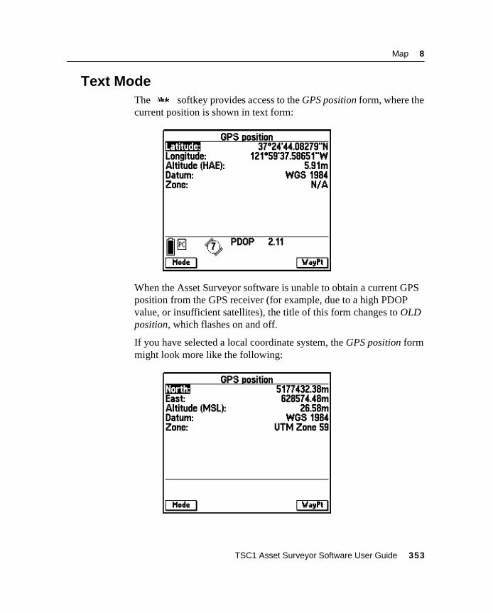
Map 8
8.8 Text ModeThe@ softkey provides access to the GPS position form, where thecurrent position is shown in text form:
When the Asset Surveyor software is unable to obtain a current GPSposition from the GPS receiver (for example, due to a high PDOPvalue, or insufficient satellites), the title of this form changes to OLDposition, which flashes on and off.
If you have selected a local coordinate system, the GPS position formmight look more like the following:
TSC1 Asset Surveyor Software User Guide 353
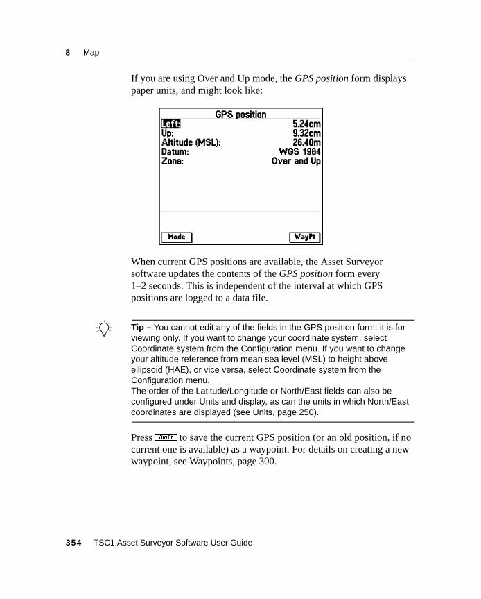
8 Map
If you are using Over and Up mode, the GPS position form displayspaper units, and might look like:
When current GPS positions are available, the Asset Surveyorsoftware updates the contents of the GPS position form every1–2 seconds. This is independent of the interval at which GPSpositions are logged to a data file.
B Tip – You cannot edit any of the fields in the GPS position form; it is forviewing only. If you want to change your coordinate system, selectCoordinate system from the Configuration menu. If you want to changeyour altitude reference from mean sea level (MSL) to height aboveellipsoid (HAE), or vice versa, select Coordinate system from theConfiguration menu.The order of the Latitude/Longitude or North/East fields can also beconfigured under Units and display, as can the units in which North/Eastcoordinates are displayed (see Units, page 250).
Pressw to save the current GPS position (or an old position, if nocurrent one is available) as a waypoint. For details on creating a newwaypoint, see Waypoints, page 300.
354 TSC1 Asset Surveyor Software User Guide
Map 8
Note – The GPS position form takes the currently configured antennadetails into account, and subtracts the height of the GPS antenna fromthe GPS positions supplied by your receiver before displaying them.The displayed positions apply therefore to the point on the groundbeneath the antenna, rather than to the Antenna Phase Center itself.
To return to the Map screen, press the@ softkey again.
8.9 FilteringFiltering lets you show or hide certain features on the Map display,depending on certain parameters which you select. Features can befiltered based on their feature type, attributes, update status, deletionstatus, or the time they were collected.
You could use filtering to show only specific types of features you areinterested in (for example, all features that still need to be updated) orto hide features that you don’t need to see so that the Map screen andthe Review data list are less cluttered.
To access Filtering options press the^ softkey on the Map displayoptions form or the Review data list. This softkey is only available if adata file is open. This opens the Filters menu for the current file. Thesame menu is opened from both locations, and any changes to filteringmade in one place affect the whole system.
For more information, see Filtering, page 102.
Note – Specified filters are associated with the open data file only. Ifyou open a new data file, the filtering options are returned to theirdefault settings. Any changes you make to the filter settings for a datafile are not stored when you close and re-open it again. If you want toturn off the filtering options for a file, uncheck the fields on the Filtersmenu, or press the7 softkey. Closing and then reopening a file willalso turn off any filters.
TSC1 Asset Surveyor Software User Guide 355
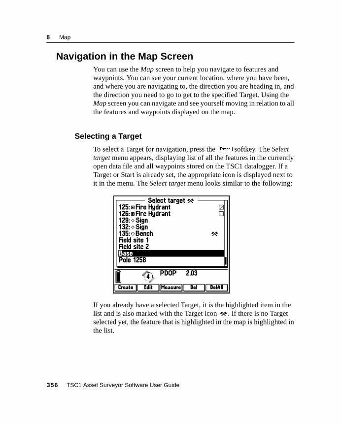
8 Map
8.10Navigation in the Map ScreenYou can use the Map screen to help you navigate to features andwaypoints. You can see your current location, where you have been,and where you are navigating to, the direction you are heading in, andthe direction you need to go to get to the specified Target. Using theMap screen you can navigate and see yourself moving in relation to allthe features and waypoints displayed on the map.
8.10.1 Selecting a Target
To select a Target for navigation, press theG softkey. The Selecttarget menu appears, displaying list of all the features in the currentlyopen data file and all waypoints stored on the TSC1 datalogger. If aTarget or Start is already set, the appropriate icon is displayed next toit in the menu. The Select target menu looks similar to the following:
If you already have a selected Target, it is the highlighted item in thelist and is also marked with the Target icon . If there is no Targetselected yet, the feature that is highlighted in the map is highlighted inthe list.
356 TSC1 Asset Surveyor Software User Guide
Map 8
TheB ,e ,x ,d , andD softkeys are also madeavailable, allowing you to create new waypoints and edit or deleteexisting waypoints. For more information, see Waypoint Operations,page 337.
Press the\ key to select the highlighted item in the list. On the Mapscreen, the crossed flag Target symbol appears over the point featureor waypoint you selected. If the Target is a line or area feature theTarget symbol appears at the selected position of that feature: its start,end, or centroid.
You can also select the Target from the Review data list and theNavigation module. For more information, see Target Selection fromReview Data List, page 94, or Selecting the Start and Target,page 331.
B Tip – To select a Target from the Map screen, first move the map cursorover the feature or waypoint to select it. Then press theG softkey. Theselected feature automatically becomes the highlighted option in theSelect target menu.
B Tip – You can create a Target at any location by moving the map cursor tothe location, pressingT orG to open the Select start or Selecttarget menu, and pressingB . A waypoint is created at the map cursorposition.
Note – You cannot select Not-in-feature positions, GPS trail positions,or features in the background file to be the Target or Start. Use themap cursor to create a waypoint at the desired location instead.
TSC1 Asset Surveyor Software User Guide 357
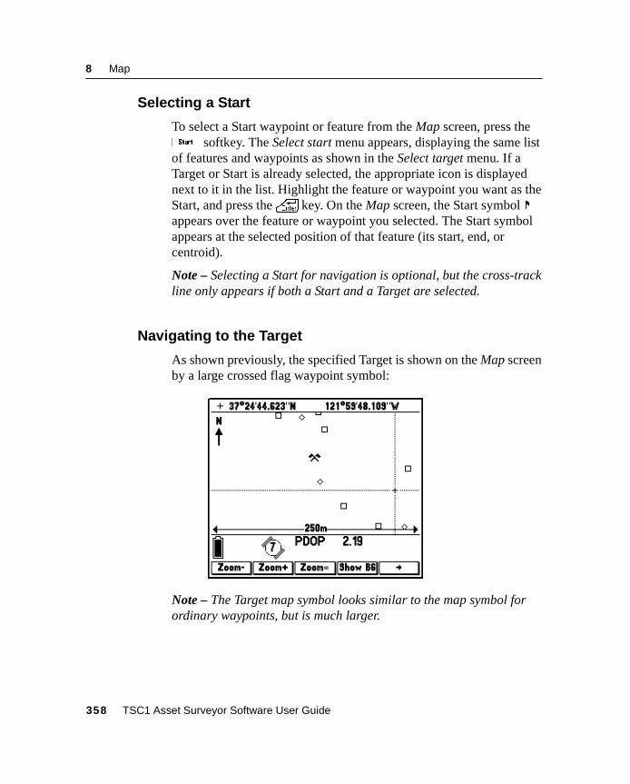
8 Map
8.10.2 Selecting a Start
To select a Start waypoint or feature from the Map screen, press theT softkey. The Select start menu appears, displaying the same listof features and waypoints as shown in the Select target menu. If aTarget or Start is already selected, the appropriate icon is displayednext to it in the list. Highlight the feature or waypoint you want as theStart, and press the\ key. On the Map screen, the Start symbolappears over the feature or waypoint you selected. The Start symbolappears at the selected position of that feature (its start, end, orcentroid).
Note – Selecting a Start for navigation is optional, but the cross-trackline only appears if both a Start and a Target are selected.
8.10.3 Navigating to the Target
As shown previously, the specified Target is shown on the Map screenby a large crossed flag waypoint symbol:
Note – The Target map symbol looks similar to the map symbol forordinary waypoints, but is much larger.
358 TSC1 Asset Surveyor Software User Guide
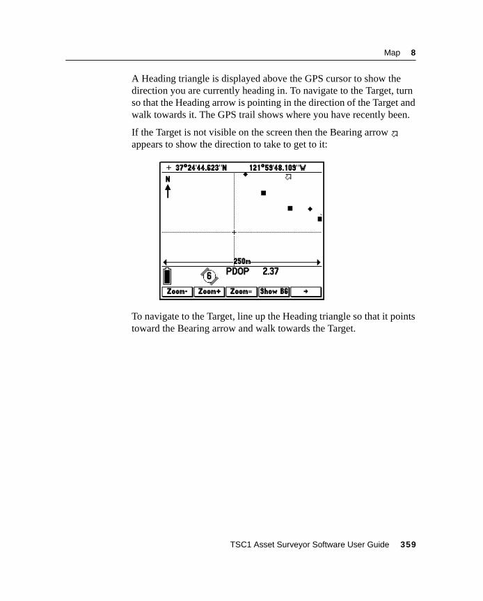
Map 8
A Heading triangle is displayed above the GPS cursor to show thedirection you are currently heading in. To navigate to the Target, turnso that the Heading arrow is pointing in the direction of the Target andwalk towards it. The GPS trail shows where you have recently been.
If the Target is not visible on the screen then the Bearing arrowappears to show the direction to take to get to it:
To navigate to the Target, line up the Heading triangle so that it pointstoward the Bearing arrow and walk towards the Target.
TSC1 Asset Surveyor Software User Guide 359
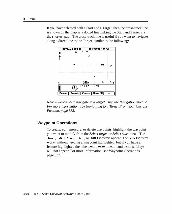
8 Map
If you have selected both a Start and a Target, then the cross-track lineis shown on the map as a dotted line linking the Start and Target viathe shortest path. The cross-track line is useful if you want to navigatealong a direct line to the Target, similar to the following:
Note – You can also navigate to a Target using the Navigation module.For more information, see Navigating to a Target From Your CurrentPosition, page 333.
8.10.4 Waypoint Operations
To create, edit, measure, or delete waypoints, highlight the waypointyou want to modify from the Select target or Select start menu. TheB ,e ,x ,d , orD softkeys appear. TheB softkeyworks without needing a waypoint highlighted, but if you have afeature highlighted then thee ,x ,d , andD softkeyswill not appear. For more information, see Waypoint Operations,page 337.
360 TSC1 Asset Surveyor Software User Guide
C H A P T E R
9
9 Receiver StatusIn this chapter:
■ Introduction
■ Receiver status form
■ DGPS status
■ Detailed status information
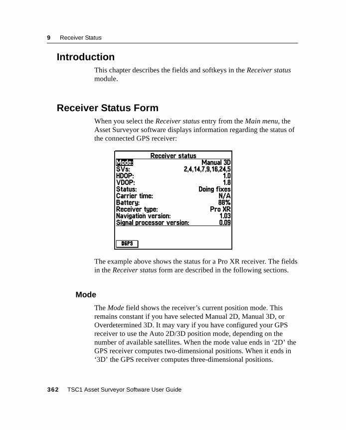
9 Receiver Status
9.1 IntroductionThis chapter describes the fields and softkeys in the Receiver statusmodule.
9.2 Receiver Status FormWhen you select the Receiver status entry from the Main menu, theAsset Surveyor software displays information regarding the status ofthe connected GPS receiver:
The example above shows the status for a Pro XR receiver. The fieldsin the Receiver status form are described in the following sections.
9.2.1 Mode
The Mode field shows the receiver’s current position mode. Thisremains constant if you have selected Manual 2D, Manual 3D, orOverdetermined 3D. It may vary if you have configured your GPSreceiver to use the Auto 2D/3D position mode, depending on thenumber of available satellites. When the mode value ends in ‘2D’ theGPS receiver computes two-dimensional positions. When it ends in‘3D’ the GPS receiver computes three-dimensional positions.
362 TSC1 Asset Surveyor Software User Guide
Receiver Status 9
9.2.2 SVs
The SVs field lists the satellites that are currently being used tocompute positions. The abbreviation ‘SV’ refers to space vehicles, theofficial term for the physical GPS satellites. The numbers listed are thePRNs (Pseudo-Random Numbers) of the satellites. Satellite PRNs aredescribed in the Mapping Systems General Reference.
Note – The number of satellite PRNs in this list is the number thatappears in the satellite icon on the left-hand side of the GPS statusline.
9.2.3 HDOP and VDOP
These two dilution of precision (DOP) values are shown on the nexttwo lines of the Receiver status form.
The VDOP (Vertical Dilution of Precision) value is a measure ofvertical accuracy; HDOP (Horizontal Dilution of Precision) is ameasure of horizontal accuracy. The PDOP, which is displayed in thestatus line, is a combination of VDOP and HDOP.
For a detailed discussion of DOP values and their significance, refer tothe Mapping Systems General Reference.
9.2.4 Status
The Status field shows the current status of the GPS receiver. Thisfield can take one of the following values:
• ‘No GPS time’: The GPS receiver has not yet acquired a signalfrom one GPS satellite, and has therefore not acquired accurateGPS time.
• ‘PDOP too high’: The current PDOP value is in excess of thePDOP mask, and consequently the GPS receiver does notcompute GPS positions.
TSC1 Asset Surveyor Software User Guide 363
9 Receiver Status
• ‘No usable satellites’: The GPS receiver is unable to find anyusable (both visible and healthy) satellites, or has lost signalsfrom all satellites (perhaps due to an obstruction).
• ‘Too few SVs’: The GPS receiver has acquired satellites, buttoo few to compute a position in the current position mode (thatis, less than three satellites in a 2D mode, less than foursatellites in Manual 3D mode, or less than five satellites inOverdetermined 3D mode).
• ‘Satellite unusable’: The GPS receiver has just rejected aparticular satellite, probably because it has become unhealthy.
• ‘Doing fixes’: The receiver is computing GPS position fixes.The current satellite constellation is therefore acceptable.
9.2.5 Carrier Time
The Carrier time field shows the time elapsed since the carrier lockwas lost. For further details on this field, see Chapter 7, Carrier PhaseData Collection, of the TSC1 Asset Surveyor Operation Manual.
9.2.6 Battery
The Battery field shows the current level of charge in the GPSreceiver’s battery, if available. This value appears as a percentage.
9.2.7 Receiver Type
The Receiver type field shows the name of the GPS receiver, forexample 4000SE, Pro XL, or Pro XR. The Asset Surveyor softwareshows the receiver’s internal name which may not precisely match thename that you use when referring to the receiver.
364 TSC1 Asset Surveyor Software User Guide
Receiver Status 9
9.2.8 Navigation Version
The Navigation version field shows the GPS receiver’s navigationfirmware version number. If you call Trimble for assistance, you maybe asked for the navigation firmware version of your GPS receiver, asthis can assist Trimble support staff to diagnose and fix a problem.
9.2.9 Signal Processor Version
The Signal processor version field shows the GPS receiver’s signalprocessor firmware version number.
9.2.10 Landstar ID
This field shows the LandStar activation code. You need this codewhen contacting your LandStar provider for activation.
9.2.11 Omnistar ID
This field shows the OmniSTAR activation code. You need this codewhen contacting your OmniSTAR provider for activation.
Note – The Landstar ID and Omnistar ID fields appear only whenconnected to a Pro XRS receiver.
For further details on activating the satellite DGPS component of yourPro XRS receiver, refer to the Pro XR/XRS Receiver Manual.
TSC1 Asset Surveyor Software User Guide 365
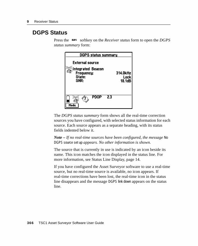
9 Receiver Status
9.3 DGPS StatusPress theg softkey on the Receiver status form to open the DGPSstatus summary form:
The DGPS status summary form shows all the real-time correctionsources you have configured, with selected status information for eachsource. Each source appears as a separate heading, with its statusfields indented below it.
Note – If no real-time sources have been configured, the message NoDGPS source set up appears. No other information is shown.
The source that is currently in use is indicated by an icon beside itsname. This icon matches the icon displayed in the status line. Formore information, see Status Line Display, page 14.
If you have configured the Asset Surveyor software to use a real-timesource, but no real-time source is available, no icon appears. Ifreal-time corrections have been lost, the real-time icon in the statusline disappears and the message DGPS link down appears on the statusline.
366 TSC1 Asset Surveyor Software User Guide
Receiver Status 9
9.4 Detailed Status InformationYou can view detailed status information on any source, not just theone that the Asset Surveyor software is currently using. This is usefulif, for example, the Asset Surveyor software is using your second orthird choice for corrections and you want to check the status details foryour first choice to find out why it is not available.
To view detailed information on a particular correction source, press@ in the DGPS status summary form. The DGPS status detailsChoice 1 form appears, showing status information for your firstchoice. Press@ repeatedly to cycle through the detail forms foryour configured choices until the choice you want is displayed. Whenthe form for your last choice is displayed, press@ again to returnto the DGPS status summary form.
Note – A DGPS status details form is only available for the real-timesources you have configured in the Real-time input form.
You can press= at any time to exit the DGPS status form and returnto the Receiver status form. You can press= at any time to exit theReceiver status form, or you can pressN to display the next form inthe stack of open windows, orM to display the Main menu.
PressS to access the Real-time input options form, where you canspecify the priority of correction sources to use, and configure any ofthem. For more information on configuring a real-time source, seeReal-Time Input Options, page 184.
TSC1 Asset Surveyor Software User Guide 367
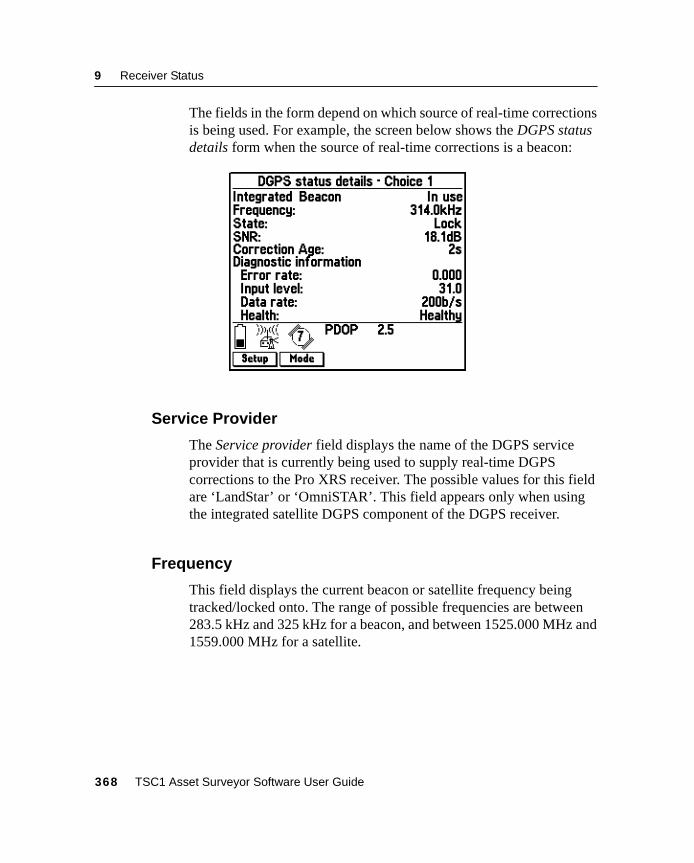
9 Receiver Status
The fields in the form depend on which source of real-time correctionsis being used. For example, the screen below shows the DGPS statusdetails form when the source of real-time corrections is a beacon:
9.4.1 Service Provider
The Service provider field displays the name of the DGPS serviceprovider that is currently being used to supply real-time DGPScorrections to the Pro XRS receiver. The possible values for this fieldare ‘LandStar’ or ‘OmniSTAR’. This field appears only when usingthe integrated satellite DGPS component of the DGPS receiver.
9.4.2 Frequency
This field displays the current beacon or satellite frequency beingtracked/locked onto. The range of possible frequencies are between283.5 kHz and 325 kHz for a beacon, and between 1525.000 MHz and1559.000 MHz for a satellite.
368 TSC1 Asset Surveyor Software User Guide
Receiver Status 9
9.4.3 State
The State field shows the current operating DGPS status of thereceiver. The possible values for this field are:
• ‘Search’: The DGPS component of the GPS receiver issearching the frequency range for a usable DGPS signal.
• ‘Track’: The DGPS component of the GPS receiver hasdetected a usable DGPS signal, but has not yet locked onto thesignal.
• ‘Lock’: The DGPS component of the GPS receiver has lockedonto a usable DGPS signal.
9.4.4 SNR
This field shows the signal-to-noise ratio (SNR), measured in decibels(dB), at the beacon or satellite DGPS frequency. For the beacon DGPScomponent, an SNR above 6.0 dB indicates that the signal is usable.For the satellite DGPS component, an SNR above 3.0 dB indicatesthat the signal is usable.
9.4.5 Correction Age
This field indicates the time, in tenths of a second, since the lastreal-time correction message was received.
9.4.6 DGPS Service Information
The fields under the DGPS service information subheading provideinformation on the DGPS subscription currently in use.
TSC1 Asset Surveyor Software User Guide 369
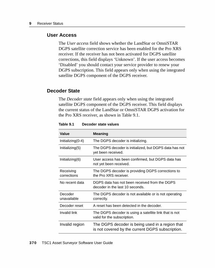
9 Receiver Status
9.4.7 User Access
The User access field shows whether the LandStar or OmniSTARDGPS satellite correction service has been enabled for the Pro XRSreceiver. If the receiver has not been activated for DGPS satellitecorrections, this field displays ‘Unknown’. If the user access becomes‘Disabled’ you should contact your service provider to renew yourDGPS subscription. This field appears only when using the integratedsatellite DGPS component of the DGPS receiver.
9.4.8 Decoder State
The Decoder state field appears only when using the integratedsatellite DGPS component of the DGPS receiver. This field displaysthe current status of the LandStar or OmniSTAR DGPS activation forthe Pro XRS receiver, as shown in Table 9.1.
Table 9.1 Decoder state values
Value Meaning
Initializing(0-4) The DGPS decoder is initializing.
Initializing(5) The DGPS decoder is initialized, but DGPS data has notyet been received.
Initializing(6) User access has been confirmed, but DGPS data hasnot yet been received.
Receivingcorrections
The DGPS decoder is providing DGPS corrections tothe Pro XRS receiver.
No recent data DGPS data has not been received from the DGPSdecoder in the last 10 seconds.
Decoderunavailable
The DGPS decoder is not available or is not operatingcorrectly.
Decoder reset A reset has been detected in the decoder.
Invalid link The DGPS decoder is using a satellite link that is notvalid for the subscription.
Invalid region The DGPS decoder is being used in a region thatis not covered by the current DGPS subscription.
370 TSC1 Asset Surveyor Software User Guide
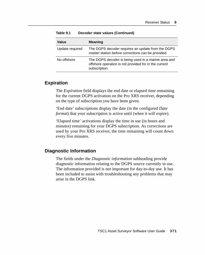
Receiver Status 9
9.4.9 Expiration
The Expiration field displays the end date or elapsed time remainingfor the current DGPS activation on the Pro XRS receiver, dependingon the type of subscription you have been given.
‘End date’ subscriptions display the date (in the configured Dateformat) that your subscription is active until (when it will expire).
‘Elapsed time’ activations display the time in use (in hours andminutes) remaining for your DGPS subscription. As corrections areused by your Pro XRS receiver, the time remaining will count downevery five minutes.
9.4.10 Diagnostic Information
The fields under the Diagnostic information subheading providediagnostic information relating to the DGPS source currently in use.The information provided is not important for day-to-day use. It hasbeen included to assist with troubleshooting any problems that mayarise in the DGPS link.
Update required The DGPS decoder requires an update from the DGPSmaster station before corrections can be provided.
No offshore The DGPS decoder is being used in a marine area andoffshore operation is not provided for in the currentsubscription.
Table 9.1 Decoder state values (Continued)
Value Meaning
TSC1 Asset Surveyor Software User Guide 371
9 Receiver Status
Quality figure
The Quality figure field displays a number representing the percentageof error-free data received in the last satellite DGPS data block. Valueslower than about 90% indicate excessive noise on the signal (possiblydue to L-band jamming) and reduce the chance that the receiver is ableto compute a real-time position using the incoming DGPS corrections.This field appears only when using the integrated satellite DGPScomponent of a Pro XRS receiver.
Tracking errors
When ‘LandStar’ is the displayed Service provider, the DGPS statusform displays the Tracking errors field. The Tracking errors field onlyappears when using the integrated satellite DGPS component of aPro XRS receiver. This field displays a ratio representing the numberof times the DGPS decoder has lost synchronization with theincoming control blocks in the last 1000 block interval. The ratiodisplayed is usually ‘0’, indicating that no tracking errors occurred.
Decoding errors
When ‘LandStar’ is the displayed Service provider, the DGPS statusform displays the Decoding errors field. The Decoding errors fielddisplays a ratio representing the number of incorrectly decoded datablocks in the last 1000 block interval. The ratio displayed is usually‘0’, indicating that no decoding errors occurred. This field onlyappears when using the integrated satellite DGPS component of aPro XRS receiver.
372 TSC1 Asset Surveyor Software User Guide
Receiver Status 9
9.4.11 Age of Sync
The Age of sync field appears only when using the integrated satelliteDGPS component of a Pro XRS receiver. This field indicates whetheror not the satellite DGPS component that your Pro XRS receiver iscurrently tracking is a valid differential signal. The value displayedrepresents the number of seconds since the receiver decoded a satellitedifferential data stream block which occurs about every 3.0 secondsunder normal operation. If the time since last sync is greater than3.0 seconds, there may be a problem with the differential data on thesignal.
9.4.12 Station ID
The Station ID field displays the ID number of the network referencestation that is being used to compute the current DGPS corrections.This field appears only when you are using the integrated satelliteDGPS component of a Pro XRS receiver.
9.4.13 Decoder Version
The Decoder version field appears only when you are using thesatellite DGPS component of a Pro XRS receiver. This field displaysthe version number of the OmniSTAR or LandStar decoder in theconnected Pro XRS receiver, depending on the Service providercurrently in use.
9.4.14 Error Rate
The Error rate field appears only when you are using the beaconDGPS component of a Pro XR or Pro XRS receiver. This field showsthe RTCM Word Error Rate, or the number of RTCM words withparity errors, expressed as a decimal fraction. An error rate below 0.1is acceptable.
TSC1 Asset Surveyor Software User Guide 373
9 Receiver Status
9.4.15 Input Level
The Input level field appears only when using the beacon DGPScomponent of a Pro XR or Pro XRS receiver. This field displays theintensity level of the electro-magnetic field, measured in decibelsabove one microvolt per meter (dBµV/M). An input level between10 dBµV/M and 100 dBµV/M is acceptable.
9.4.16 Data Rate
The Data rate field identifies the data modulation rates from thebeacon DGPS component of the Pro XR or Pro XRS receiver. Thisfield only appears when using the beacon DGPS component of aPro XR or Pro XRS receiver.
9.4.17 Health
The Health field appears only when using the beacon DGPScomponent of a Pro XR or Pro XRS receiver. This field showswhether the signal received from the beacon DGPS component is‘Healthy’, ‘Unhealthy’, or ‘Unmonitored’. The Asset Surveyorsoftware will not use ‘Unhealthy’ beacon corrections to correct GPSpositions in real-time.
Note – The Health field only appears when connected to a Pro XRSreceiver, or a Pro XR receiver with a firmware version of 1.05 or later.
374 TSC1 Asset Surveyor Software User Guide

C H A P T E R
10
10 Satellite InformationIn this chapter:
■ Introduction
■ Text mode
■ Graphical modes
10 Satellite Information
10.1IntroductionIf you select the Satellite information entry from the Main menu, theAsset Surveyor software displays information for each satellite in theGPS receiver’s tracking set.
There are three modes of displaying the satellite information. They arethe Text mode, the Skyplot graphical mode, and the SNR levelsgraphical mode. Use the@ softkey to cycle through these modes.
Whenever you enter the Satellite information screen, the AssetSurveyor software displays the mode you last used. The first time youopen the Satellite information screen the default screen that appears isthe Skyplot graphical mode.
You can exit the Satellite information screen by pressing= anytime.
376 TSC1 Asset Surveyor Software User Guide
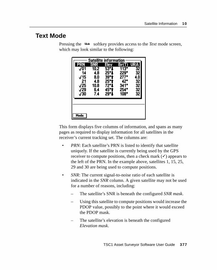
Satellite Information 10
10.2Text ModePressing the@ softkey provides access to the Text mode screen,which may look similar to the following:
This form displays five columns of information, and spans as manypages as required to display information for all satellites in thereceiver’s current tracking set. The columns are:
• PRN: Each satellite’s PRN is listed to identify that satelliteuniquely. If the satellite is currently being used by the GPSreceiver to compute positions, then a check mark (�) appears tothe left of the PRN. In the example above, satellites 1, 15, 25,29 and 30 are being used to compute positions.
• SNR: The current signal-to-noise ratio of each satellite isindicated in the SNR column. A given satellite may not be usedfor a number of reasons, including:
– The satellite’s SNR is beneath the configured SNR mask.
– Using this satellite to compute positions would increase thePDOP value, possibly to the point where it would exceedthe PDOP mask.
– The satellite’s elevation is beneath the configuredElevation mask.
TSC1 Asset Surveyor Software User Guide 377
10 Satellite Information
If a satellite is marked as ‘unhealthy’ by the GPS ControlSegment, the characters ‘U/H’ appear in the SNR column forthat satellite. The GPS receiver does not use unhealthy satellitesto compute positions.
• Elev: This column shows the current elevation of each satelliteabove the horizon. Typically, satellites which are far below theconfigured elevation mask are dropped from the receiver’stracking set, so that the receiver can concentrate on satelliteswhich are currently visible.
Beside each satellite’s elevation is an arrow indicating whetherthe satellite is moving from a lower elevation to a higherelevation (rising, indicated by ) or moving from a higherelevation to a lower elevation (setting, indicated by ).
• Br(T) or Br(M): This column shows the current bearing to eachsatellite in the tracking set. This bearing is shown relative toeither true north (T) or magnetic north (M), as determined bythe currently configured North reference.
B Tip – You can change the value of the North reference field in the Unitsand display configuration form, under the Configuration menu.
• URA: This column shows the User Range Accuracy value foreach satellite in the tracking set. URA is an estimate of theaccuracy of the pseudo-range measurement to each satellite. Itis based on a number of factors, including the age of the data,the type of clock in the satellite, the satellite orbit and clockbehavior, and whether Selective Availability (S/A) is activatedfor the satellite.
378 TSC1 Asset Surveyor Software User Guide
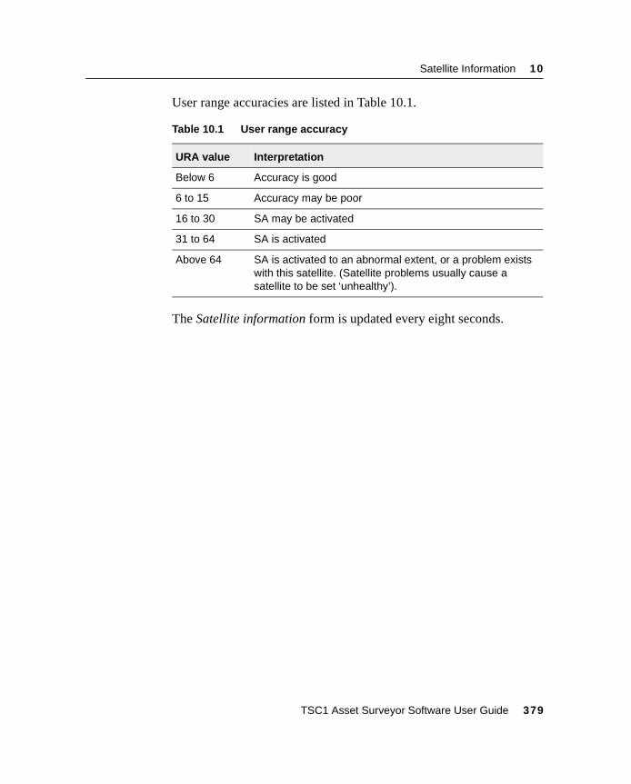
Satellite Information 10
User range accuracies are listed in Table 10.1.
The Satellite information form is updated every eight seconds.
Table 10.1 User range accuracy
URA value Interpretation
Below 6 Accuracy is good
6 to 15 Accuracy may be poor
16 to 30 SA may be activated
31 to 64 SA is activated
Above 64 SA is activated to an abnormal extent, or a problem existswith this satellite. (Satellite problems usually cause asatellite to be set ‘unhealthy’).
TSC1 Asset Surveyor Software User Guide 379
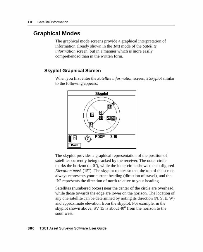
10 Satellite Information
10.3Graphical ModesThe graphical mode screens provide a graphical interpretation ofinformation already shown in the Text mode of the Satelliteinformation screen, but in a manner which is more easilycomprehended than in the written form.
10.3.1 Skyplot Graphical Screen
When you first enter the Satellite information screen, a Skyplot similarto the following appears:
The skyplot provides a graphical representation of the position ofsatellites currently being tracked by the receiver. The outer circlemarks the horizon (at 0o), while the inner circle shows the configuredElevation mask (15o). The skyplot rotates so that the top of the screenalways represents your current heading (direction of travel), and the‘N’ represents the direction of north relative to your heading.
Satellites (numbered boxes) near the center of the circle are overhead,while those towards the edge are lower on the horizon. The location ofany one satellite can be determined by noting its direction (N, S, E, W)and approximate elevation from the skyplot. For example, in theskyplot shown above, SV 15 is about 40o from the horizon to thesouthwest.
380 TSC1 Asset Surveyor Software User Guide
Satellite Information 10
The SVs shown as black boxes are those that are currently being usedby the receiver to compute GPS positions. SVs with clear boxes arethose that are being tracked by the receiver, but are not being used tocompute positions because their elevation or SNR are below theconfigured masks.
Because the skyplot’s rotation is relative to your heading, the skyplotstops rotating when your velocity is too slow to calculate an accurateheading, and the message Heading locked appears in the status line. Formore information, see Heading Lock, page 326.
TSC1 Asset Surveyor Software User Guide 381
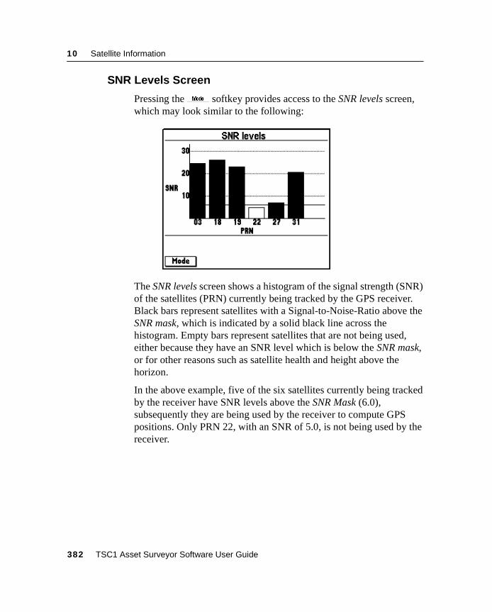
10 Satellite Information
10.3.2 SNR Levels Screen
Pressing the@ softkey provides access to the SNR levels screen,which may look similar to the following:
The SNR levels screen shows a histogram of the signal strength (SNR)of the satellites (PRN) currently being tracked by the GPS receiver.Black bars represent satellites with a Signal-to-Noise-Ratio above theSNR mask, which is indicated by a solid black line across thehistogram. Empty bars represent satellites that are not being used,either because they have an SNR level which is below the SNR mask,or for other reasons such as satellite health and height above thehorizon.
In the above example, five of the six satellites currently being trackedby the receiver have SNR levels above the SNR Mask (6.0),subsequently they are being used by the receiver to compute GPSpositions. Only PRN 22, with an SNR of 5.0, is not being used by thereceiver.
382 TSC1 Asset Surveyor Software User Guide

C H A P T E R
11
11 HelpIn this chapter:
■ Introduction
■ Getting help
■ Getting help in different languages
■ Exiting the help
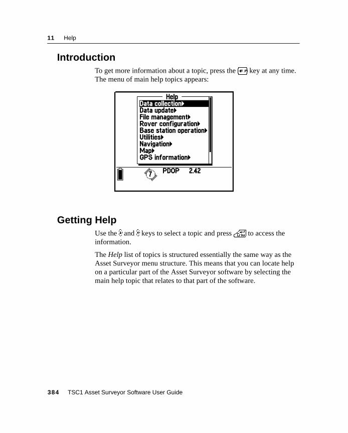
11 Help
11.1IntroductionTo get more information about a topic, press the? key at any time.The menu of main help topics appears:
11.2Getting HelpUse the _ and ) keys to select a topic and press\ to access theinformation.
The Help list of topics is structured essentially the same way as theAsset Surveyor menu structure. This means that you can locate helpon a particular part of the Asset Surveyor software by selecting themain help topic that relates to that part of the software.
384 TSC1 Asset Surveyor Software User Guide
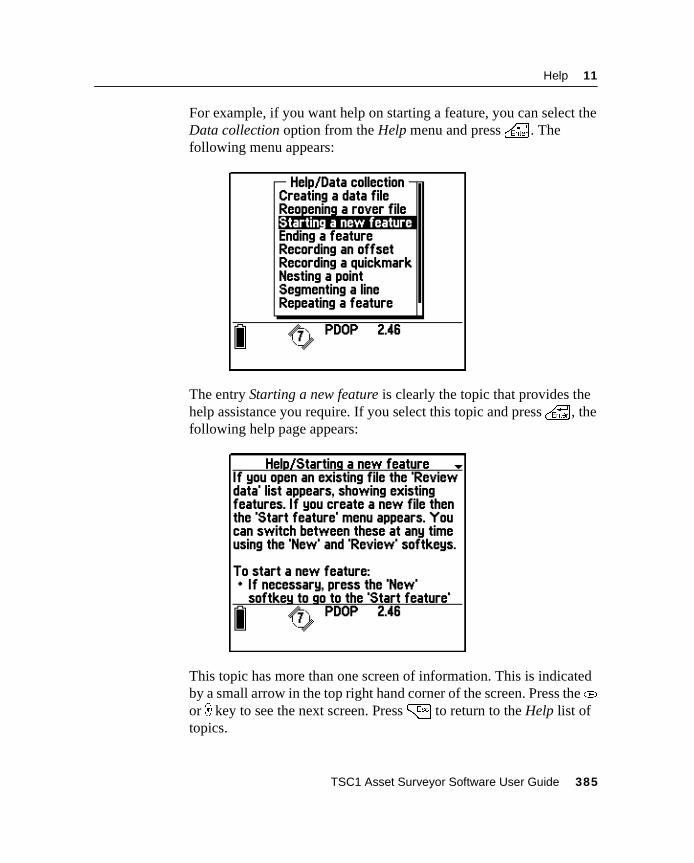
Help 11
For example, if you want help on starting a feature, you can select theData collection option from the Help menu and press\ . Thefollowing menu appears:
The entry Starting a new feature is clearly the topic that provides thehelp assistance you require. If you select this topic and press\ , thefollowing help page appears:
This topic has more than one screen of information. This is indicatedby a small arrow in the top right hand corner of the screen. Press the(or ) key to see the next screen. Press= to return to the Help list oftopics.
TSC1 Asset Surveyor Software User Guide 385
11 Help
11.3Getting Help in Different LanguagesOnly English help is loaded onto the TSC1 datalogger by default.Translated help files are available for French, German, Portuguese,Russian, and Spanish. For details on transferring help files onto theTSC1 datalogger, see Transferring Data Files to and from the PC,page 154. Contact your local Trimble dealer for information on theavailability of help files for other languages.
11.4Exiting the HelpTo exit the online help system, return to the Help screen and press= . You can also use theM andN keys to access the AssetSurveyor software while leaving the Help system open.
386 TSC1 Asset Surveyor Software User Guide

A P P E N D I X
A
A Installing the Asset SurveyorSoftwareIn this chapter:■ Introduction
■ Equipment required for installation
■ Installing the Asset Surveyor version 5.20 software on your TSC1datalogger
■ Loading options onto the TSC1 datalogger
A Installing the Asset Surveyor Software
1.1 IntroductionIf you received this document with a new TSC1 datalogger then theAsset Surveyor version 5.20 software is already installed on thedatalogger. If that is the case, you may disregard this chapter.
If you want to install the Asset Surveyor version 5.20 software onto anexisting TSC1 datalogger (with an earlier version of the AssetSurveyor software or with the Trimble Survey Controller softwarealready installed), then you should read this chapter carefully andfollow the instructions it contains. You can install the Asset Surveyorversion 5.20 software onto the TSC1 datalogger using the installationCD provided.
1.2 Equipment Required for InstallationIn order to install the Asset Surveyor version 5.20 software onto theTSC1 datalogger, you require the following equipment:
• An IBM-compatible personal computer running MicrosoftWindows 95, Windows 98, or Windows NT, with at least oneavailable serial RS232 port, at least 8 MB of free hard diskspace, and a CD-ROM drive.
• Your TSC1 datalogger.
• The Asset Surveyor version 5.20 CD-ROM (P/N 34186-20).
• Optionally, a 9-pin to 25-pin converter. This is required if yourpersonal computer has a 25-pin serial port connector on itsCOM1 or COM2 port.
• Optionally, a Trimble Support Module (TSM™) batterycharger. A TSM can be used to provide an external source ofpower for the installation, rather than using the TSC1datalogger’s internal battery. An adapter cable is required toconnect the TSM to your TSC1 datalogger. The cable requireddepends on the TSM model you are using.
388 TSC1 Asset Surveyor Software User Guide
Installing the Asset Surveyor Software A
Note – Although the Asset Surveyor software installation can beaccomplished by using power from the TSC1 datalogger’s internallithium battery, it is recommended that you use the TSM as an externalsource of power. This prevents accidental termination of theinstallation process while running off a discharged battery.
1.3 Installing the Asset Surveyor Version 5.20 Softwareon Your TSC1 Datalogger
Before commencing the installation of the Asset Surveyor version5.20 software it may be necessary to perform an option upgrade if:
• the TSC1 datalogger is currently running the Trimble SurveyController software, and does not have a valid license for theAsset Surveyor software; or
• the current Asset Surveyor support warranty has expired.
For instructions on performing the option upgrade, see LoadingOptions onto the TSC1 Datalogger, page 398. When you havecompleted the option upgrade, you can proceed with the AssetSurveyor software installation. The following instructions enable youto install version 5.20 of the Asset Surveyor software onto a TSC1datalogger.
C Warning – The Asset Surveyor software completely erases the contentsof the TSC1 datalogger’s memory when the software is installed onto theTSC1. The installation does not commence until you have transferred anddeleted all data files from the TSC1 datalogger.
To install the Asset Surveyor software onto your TSC1 dataloggerusing a TSM as an external source of power, connect the equipmentlisted on page A-388, as shown in Figure 1.1.
TSC1 Asset Surveyor Software User Guide 389
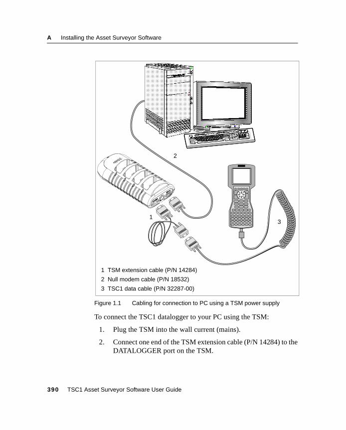
A Installing the Asset Surveyor Software
Figure 1.1 Cabling for connection to PC using a TSM power supply
To connect the TSC1 datalogger to your PC using the TSM:
1. Plug the TSM into the wall current (mains).
2. Connect one end of the TSM extension cable (P/N 14284) to theDATALOGGER port on the TSM.
1 TSM extension cable (P/N 14284)
2 Null modem cable (P/N 18532)
3 TSC1 data cable (P/N 32287-00)
2
31
390 TSC1 Asset Surveyor Software User Guide
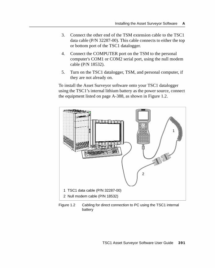
Installing the Asset Surveyor Software A
3. Connect the other end of the TSM extension cable to the TSC1data cable (P/N 32287-00). This cable connects to either the topor bottom port of the TSC1 datalogger.
4. Connect the COMPUTER port on the TSM to the personalcomputer's COM1 or COM2 serial port, using the null modemcable (P/N 18532).
5. Turn on the TSC1 datalogger, TSM, and personal computer, ifthey are not already on.
To install the Asset Surveyor software onto your TSC1 dataloggerusing the TSC1’s internal lithium battery as the power source, connectthe equipment listed on page A-388, as shown in Figure 1.2.
Figure 1.2 Cabling for direct connection to PC using the TSC1 internalbattery
1 TSC1 data cable (P/N 32287-00)
2 Null modem cable (P/N 18532)
1
2
TSC1 Asset Surveyor Software User Guide 391
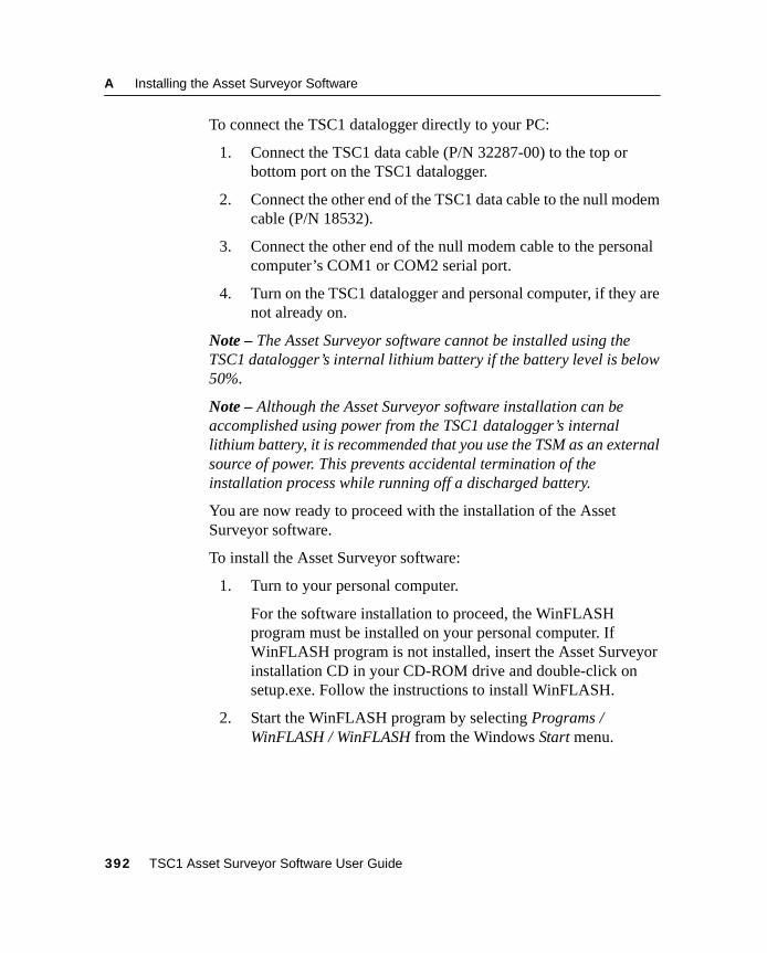
A Installing the Asset Surveyor Software
To connect the TSC1 datalogger directly to your PC:
1. Connect the TSC1 data cable (P/N 32287-00) to the top orbottom port on the TSC1 datalogger.
2. Connect the other end of the TSC1 data cable to the null modemcable (P/N 18532).
3. Connect the other end of the null modem cable to the personalcomputer’s COM1 or COM2 serial port.
4. Turn on the TSC1 datalogger and personal computer, if they arenot already on.
Note – The Asset Surveyor software cannot be installed using theTSC1 datalogger’s internal lithium battery if the battery level is below50%.
Note – Although the Asset Surveyor software installation can beaccomplished using power from the TSC1 datalogger’s internallithium battery, it is recommended that you use the TSM as an externalsource of power. This prevents accidental termination of theinstallation process while running off a discharged battery.
You are now ready to proceed with the installation of the AssetSurveyor software.
To install the Asset Surveyor software:
1. Turn to your personal computer.
For the software installation to proceed, the WinFLASHprogram must be installed on your personal computer. IfWinFLASH program is not installed, insert the Asset Surveyorinstallation CD in your CD-ROM drive and double-click onsetup.exe. Follow the instructions to install WinFLASH.
2. Start the WinFLASH program by selecting Programs /WinFLASH / WinFLASH from the Windows Start menu.
392 TSC1 Asset Surveyor Software User Guide
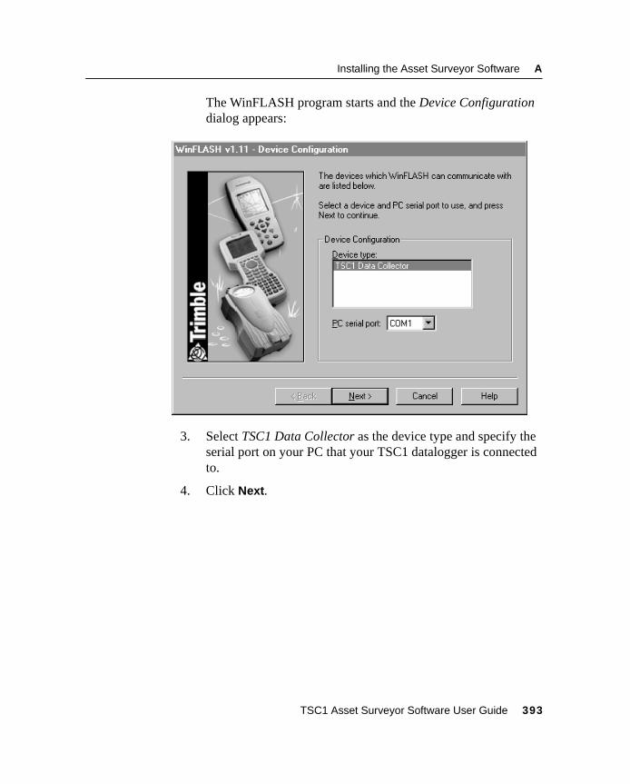
Installing the Asset Surveyor Software A
The WinFLASH program starts and the Device Configurationdialog appears:
3. Select TSC1 Data Collector as the device type and specify theserial port on your PC that your TSC1 datalogger is connectedto.
4. Click Next.
TSC1 Asset Surveyor Software User Guide 393
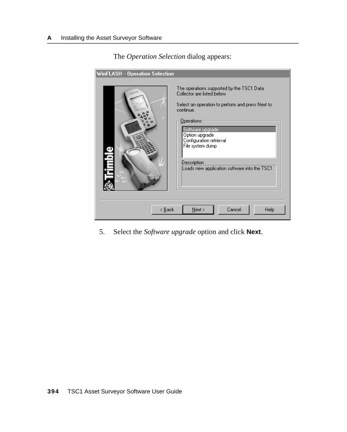
A Installing the Asset Surveyor Software
The Operation Selection dialog appears:
5. Select the Software upgrade option and click Next.
394 TSC1 Asset Surveyor Software User Guide
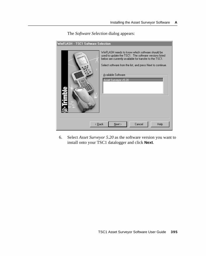
Installing the Asset Surveyor Software A
The Software Selection dialog appears:
6. Select Asset Surveyor 5.20 as the software version you want toinstall onto your TSC1 datalogger and click Next.
TSC1 Asset Surveyor Software User Guide 395
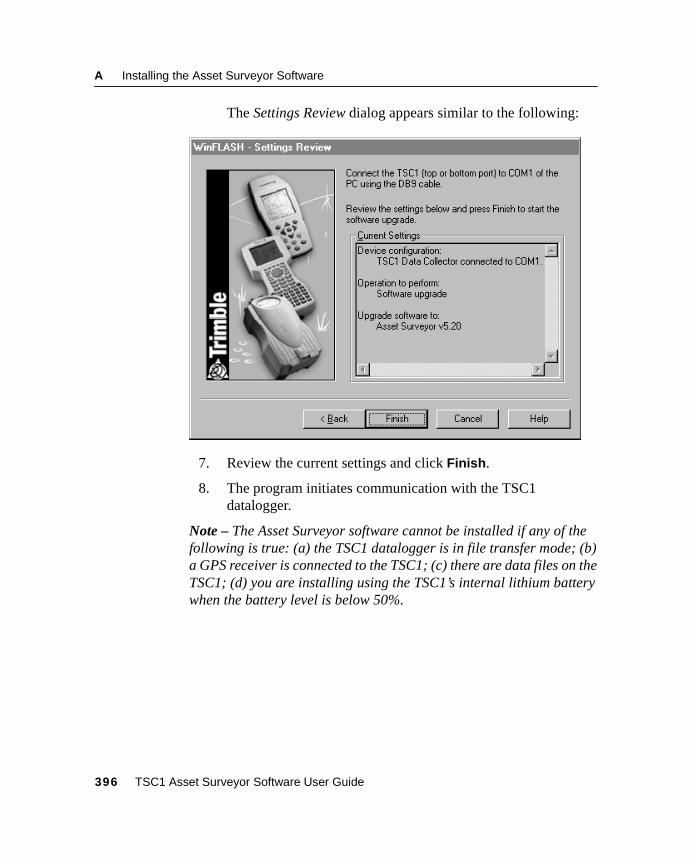
A Installing the Asset Surveyor Software
The Settings Review dialog appears similar to the following:
7. Review the current settings and click Finish.
8. The program initiates communication with the TSC1datalogger.
Note – The Asset Surveyor software cannot be installed if any of thefollowing is true: (a) the TSC1 datalogger is in file transfer mode; (b)a GPS receiver is connected to the TSC1; (c) there are data files on theTSC1; (d) you are installing using the TSC1’s internal lithium batterywhen the battery level is below 50%.
396 TSC1 Asset Surveyor Software User Guide
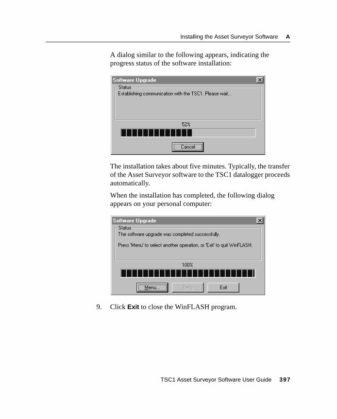
Installing the Asset Surveyor Software A
A dialog similar to the following appears, indicating theprogress status of the software installation:
The installation takes about five minutes. Typically, the transferof the Asset Surveyor software to the TSC1 datalogger proceedsautomatically.
When the installation has completed, the following dialogappears on your personal computer:
9. Click Exit to close the WinFLASH program.
TSC1 Asset Surveyor Software User Guide 397
A Installing the Asset Surveyor Software
10. Your TSC1 datalogger now performs a cold boot andautomatically starts up the newly installed software.
The Trimble logo screen appears just after rebooting identifyingthe new Asset Surveyor software and also showing the softwareversion number (5.20).
11. If you have just installed version 5.20 of the Asset Surveyorsoftware onto your TSC1 datalogger, you must now reload anydata dictionaries, coordinate system sites, and waypoints, asthese are erased when the software on the TSC1 datalogger isinstalled.
1.4 Loading Options onto the TSC1 DataloggerIt may be necessary to perform an options upgrade on the TSC1datalogger before installing the Asset Surveyor software if:
• the TSC1 datalogger is currently running the Survey Controllersoftware, and does not have a valid license for the AssetSurveyor software
• the current Asset Surveyor support warranty has expired.
The following steps provide instructions for upgrading the softwareoption on the TSC1 datalogger. Note that you must have a passwordprovided by Trimble in order to perform an upgrade.
Note – The option upgrade program does not install the AssetSurveyor 5.20 software on your TSC1 datalogger. Once the optionupgrade program has been successfully completed, you must installthe Asset Surveyor version 5.20 software, as described in Installingthe Asset Surveyor Version 5.20 Software on Your TSC1 Datalogger,page 389.
For the option installation using a TSM as an external source ofpower, connect the equipment as shown in Figure 1.1 on page 390.
398 TSC1 Asset Surveyor Software User Guide
Installing the Asset Surveyor Software A
For the option installation using the TSC1 datalogger’s internallithium battery as the power source, connect the equipment as shownin Figure 1.2 on page 391.
Note – The Asset Surveyor software cannot be installed using theTSC1 datalogger’s internal lithium battery if the battery level is below50%.
Note – Although the TSC1 option installation can be accomplishedusing power from the TSC1 datalogger’s internal lithium battery, it isrecommended that the TSC1 datalogger uses the TSM as an externalsource of power. This prevents accidental termination of theinstallation process while running off a discharged battery.
Before you can install options, the WinFLASH program, which isused to install the Asset Surveyor software onto your TSC1datalogger, must be installed onto your personal computer. TheWinFLASH program can be downloaded from the Trimble web site at:
• http://www.trimble.com/support/files/assets1.htm
Download the file as520web.exe from the above address. This fileincludes the latest version of the Asset Surveyor software. Once youhave downloaded the file, double-click it to begin installing theWinFLASH software, and follow the instructions on the screen.
You are now ready to proceed with the option installation.
TSC1 Asset Surveyor Software User Guide 399
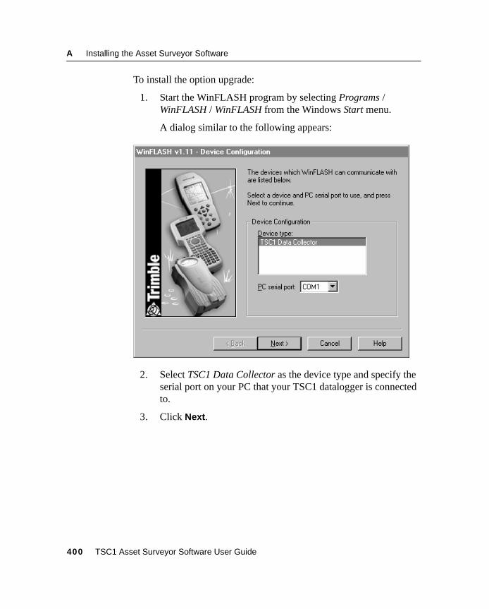
A Installing the Asset Surveyor Software
To install the option upgrade:
1. Start the WinFLASH program by selecting Programs /WinFLASH / WinFLASH from the Windows Start menu.
A dialog similar to the following appears:
2. Select TSC1 Data Collector as the device type and specify theserial port on your PC that your TSC1 datalogger is connectedto.
3. Click Next.
400 TSC1 Asset Surveyor Software User Guide
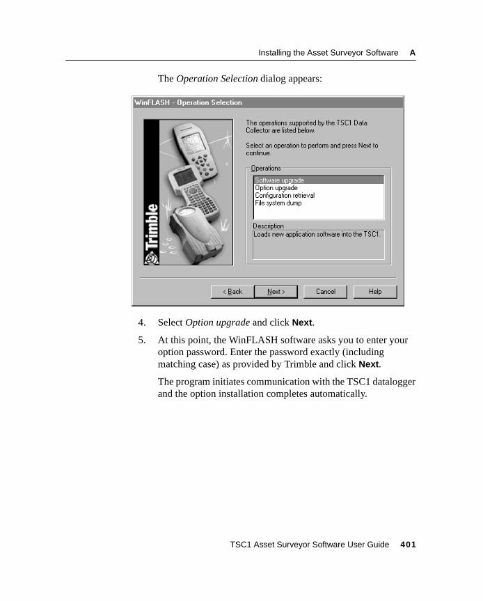
Installing the Asset Surveyor Software A
The Operation Selection dialog appears:
4. Select Option upgrade and click Next.
5. At this point, the WinFLASH software asks you to enter youroption password. Enter the password exactly (includingmatching case) as provided by Trimble and click Next.
The program initiates communication with the TSC1 dataloggerand the option installation completes automatically.
TSC1 Asset Surveyor Software User Guide 401

A Installing the Asset Surveyor Software
402 TSC1 Asset Surveyor Software User Guide

A P P E N D I X
BA P P E N D I X
B
B Troubleshooting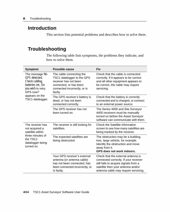
B Troubleshooting
2.1 IntroductionThis section lists potential problems and describes how to solve them.
2.2 TroubleshootingThe following table lists symptoms, the problems they indicate, andhow to solve them.
Symptom Possible cause Fix
The message NoGPS detected.Check cabling,batteries etc. Doyou wish to retryGPS now?appears on theTSC1 datalogger.
The cable connecting theTSC1 datalogger to the GPSreceiver has not beenconnected, or has beenconnected incorrectly, or isfaulty.
Check that the cable is connectedcorrectly. If it appears to be correctand all other equipment appears tobe correct, the cable may requireservicing.
The GPS receiver’s battery isdead, or has not beenconnected correctly.
Check that the battery is correctlyconnected and is charged, or connectto an external power source.
The GPS receiver has notbeen turned on.
The Series 4000 and Site Surveyor4400 receivers must be manuallyturned on before the Asset Surveyorsoftware can communicate with them.
The receiver hasnot acquired asatellite withinthree minutes ofthe TSC1datalogger beingturned on.
The receiver is still looking forsatellites.
Check the Satellite informationscreen to see how many satellites arebeing tracked by the receiver.
The expected satellites arebeing obstructed.
The obstruction may be a building,tree, large vehicle, for example.Identify the obstruction and moveaway from it.GPS does not work indoors.
Your GPS receiver’s externalantenna (or antenna cable)has not been connected, hasbeen connected incorrectly, oris faulty.
Check that the external antenna isconnected correctly. If your receiverstill fails to acquire signals from asatellite then your antenna and/orantenna cable may require servicing.
404 TSC1 Asset Surveyor Software User Guide
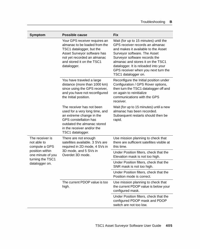
Troubleshooting B
Your GPS receiver requires analmanac to be loaded from theTSC1 datalogger, but theAsset Surveyor software hasnot yet recorded an almanacand stored it on the TSC1datalogger.
Wait (for up to 15 minutes) until theGPS receiver records an almanacand makes it available to the AssetSurveyor software. The AssetSurveyor software records thealmanac and stores it on the TSC1datalogger. It is reloaded into yourGPS receiver when you next turn theTSC1 datalogger on.
You have traveled a largedistance (more than 1000 km)since using the GPS receiver,and you have not reconfiguredthe Initial position.
Reconfigure the Initial position underConfiguration / GPS Rover options,then turn the TSC1 datalogger off andon again to reinitializecommunications with the GPSreceiver.
The receiver has not beenused for a very long time, andan extreme change in theGPS constellation hasoutdated the almanac storedin the receiver and/or theTSC1 datalogger.
Wait (for up to 15 minutes) until a newalmanac has been recorded.Subsequent restarts should then berapid.
The receiver isnot able tocompute a GPSposition withinone minute of youturning the TSC1datalogger on.
There are not enoughsatellites available. 3 SVs arerequired in 2D mode, 4 SVs in3D mode, and 5 SVs inOverdet 3D mode.
Use mission planning to check thatthere are sufficient satellites visible atthis time.
Under Position filters, check that theElevation mask is not too high.
Under Position filters, check that theSNR mask is not too high.
Under Position filters, check that thePosition mode is correct.
The current PDOP value is toohigh.
Use mission planning to check thatthe current PDOP value is below yourconfigured mask.
Under Position filters, check that theconfigured PDOP mask and PDOPswitch are not too low.
Symptom Possible cause Fix
TSC1 Asset Surveyor Software User Guide 405
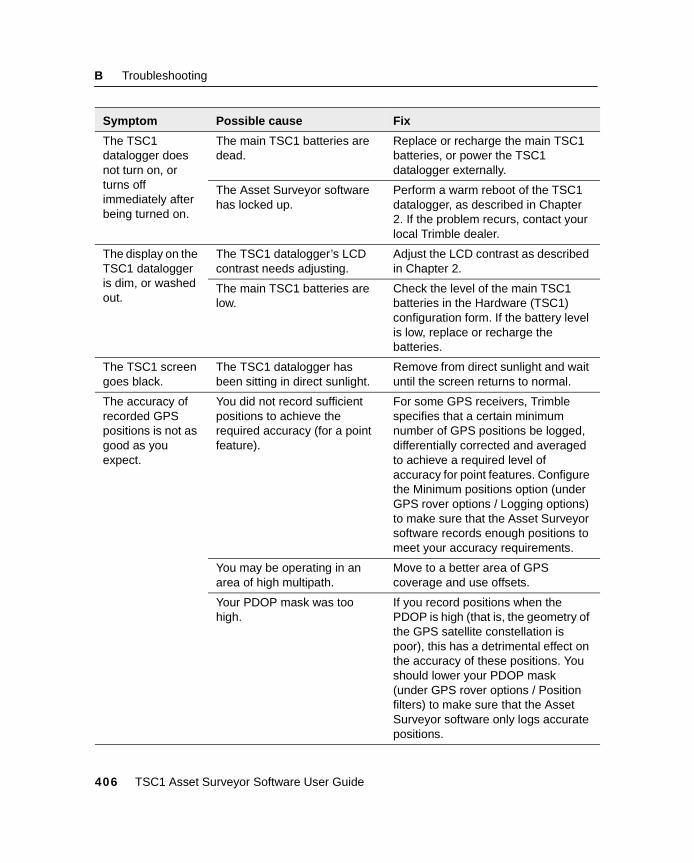
B Troubleshooting
The TSC1datalogger doesnot turn on, orturns offimmediately afterbeing turned on.
The main TSC1 batteries aredead.
Replace or recharge the main TSC1batteries, or power the TSC1datalogger externally.
The Asset Surveyor softwarehas locked up.
Perform a warm reboot of the TSC1datalogger, as described in Chapter2. If the problem recurs, contact yourlocal Trimble dealer.
The display on theTSC1 dataloggeris dim, or washedout.
The TSC1 datalogger’s LCDcontrast needs adjusting.
Adjust the LCD contrast as describedin Chapter 2.
The main TSC1 batteries arelow.
Check the level of the main TSC1batteries in the Hardware (TSC1)configuration form. If the battery levelis low, replace or recharge thebatteries.
The TSC1 screengoes black.
The TSC1 datalogger hasbeen sitting in direct sunlight.
Remove from direct sunlight and waituntil the screen returns to normal.
The accuracy ofrecorded GPSpositions is not asgood as youexpect.
You did not record sufficientpositions to achieve therequired accuracy (for a pointfeature).
For some GPS receivers, Trimblespecifies that a certain minimumnumber of GPS positions be logged,differentially corrected and averagedto achieve a required level ofaccuracy for point features. Configurethe Minimum positions option (underGPS rover options / Logging options)to make sure that the Asset Surveyorsoftware records enough positions tomeet your accuracy requirements.
You may be operating in anarea of high multipath.
Move to a better area of GPScoverage and use offsets.
Your PDOP mask was toohigh.
If you record positions when thePDOP is high (that is, the geometry ofthe GPS satellite constellation ispoor), this has a detrimental effect onthe accuracy of these positions. Youshould lower your PDOP mask(under GPS rover options / Positionfilters) to make sure that the AssetSurveyor software only logs accuratepositions.
Symptom Possible cause Fix
406 TSC1 Asset Surveyor Software User Guide
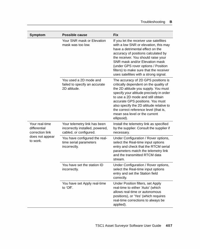
Troubleshooting B
Your SNR mask or Elevationmask was too low.
If you let the receiver use satelliteswith a low SNR or elevation, this mayhave a detrimental effect on theaccuracy of positions calculated bythe receiver. You should raise yourSNR mask and/or Elevation mask(under GPS rover options / Positionfilters) to make sure that the receiveruses satellites with a strong signal.
You used a 2D mode andfailed to specify an accurate2D altitude.
The accuracy of 2D GPS positions iscritically dependent on the quality ofthe 2D altitude you supply. You mustspecify your altitude precisely in orderto use a 2D mode and still obtainaccurate GPS positions. You mustalso specify the 2D altitude relative tothe correct reference level (that is,mean sea level or the currentellipsoid).
Your real-timedifferentialcorrection linkdoes not appearto work.
Your telemetry link has beenincorrectly installed, powered,cabled, or configured.
Install the telemetry link as specifiedby the supplier. Consult the supplier ifnecessary.
You have configured the real-time serial parametersincorrectly.
Under Configuration / Rover options,select the Real-time input optionsentry and check that the RTCM serialparameters match the telemetry linkand the transmitted RTCM datastream.
You have set the station IDincorrectly.
Under Configuration / Rover options,select the Real-time input optionsentry and set the Station fieldcorrectly.
You have set Apply real-timeto ‘Off’.
Under Position filters, set Applyreal-time to either ‘Auto’ (whichallows real-time or autonomouspositions), or ‘Yes’ (which requiresreal-time corrections to always beapplied).
Symptom Possible cause Fix
TSC1 Asset Surveyor Software User Guide 407
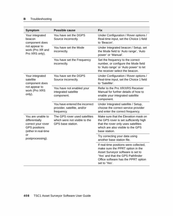
B Troubleshooting
Your integratedbeaconcomponent doesnot appear towork (Pro XR andPro XRS only).
You have set the DGPSSource incorrectly.
Under Configuration / Rover options /Real-time input, set the Choice 1 fieldto ‘Beacon’.
You have set the Modeincorrectly.
Under Integrated beacon / Setup, setthe Mode field to ‘Auto range’, ‘Autopower’ or ‘Manual’.
You have set the Frequencyincorrectly.
Set the frequency to the correctnumber, or configure the Mode fieldto ‘Auto range’ or ‘Auto power’ to letthe receiver select the beacon.
Your integratedsatellitecomponent doesnot appear towork (Pro XRSonly).
You have set the DGPSSource incorrectly.
Under Configuration / Rover options /Real-time input, set the Choice 1 fieldto ‘Satellite’.
You have not enabled yourintegrated satellitecomponent.
Refer to the Pro XR/XRS ReceiverManual for further details of how toenable your integrated satellitecomponent.
You have entered the incorrectprovider, satellite, and/orfrequency.
Under Integrated satellite / Setup,choose the correct service providerand enter the correct frequency.
You are unable todifferentiallycorrect your roverGPS positions(either in real-timeorpostprocessing).
The GPS rover used satelliteswhich were not visible to theGPS base station.
Make sure that the Elevation mask onthe GPS rover is set sufficiently highthat the rover only uses satelliteswhich are also visible to the GPSbase station.
Try correcting your data usinganother base station file.
If real-time positions were collected,make sure the PPRT option in theAsset Surveyor software is set to‘Yes’ and that the GPS PathfinderOffice software has the PPRT optionset to ‘Yes’.
Symptom Possible cause Fix
408 TSC1 Asset Surveyor Software User Guide
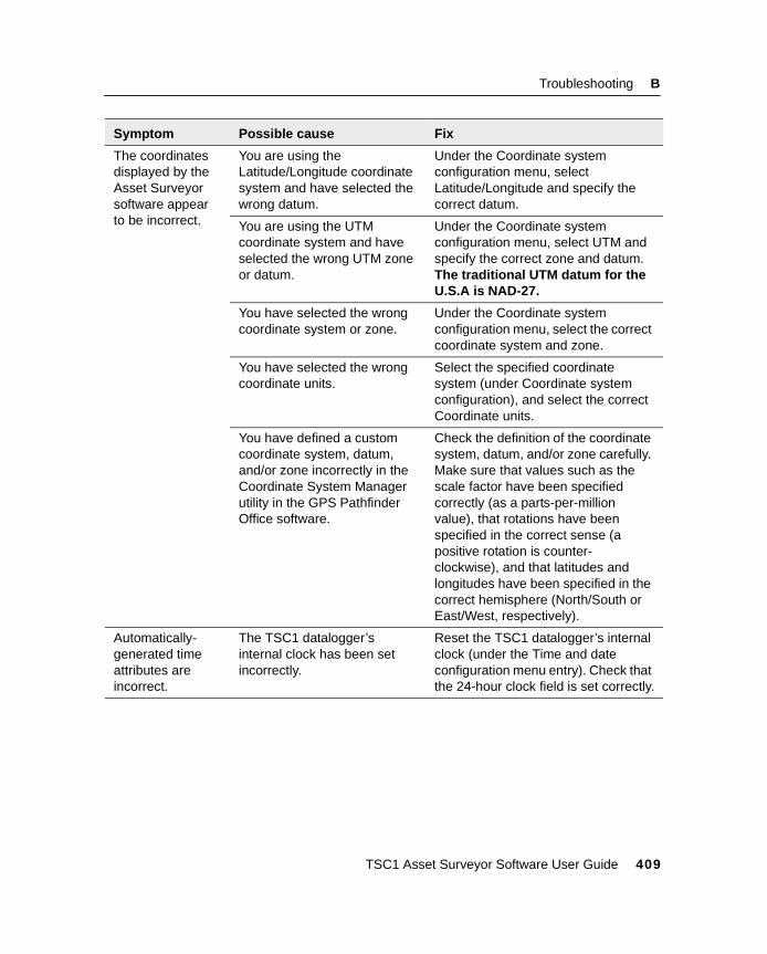
Troubleshooting B
The coordinatesdisplayed by theAsset Surveyorsoftware appearto be incorrect.
You are using theLatitude/Longitude coordinatesystem and have selected thewrong datum.
Under the Coordinate systemconfiguration menu, selectLatitude/Longitude and specify thecorrect datum.
You are using the UTMcoordinate system and haveselected the wrong UTM zoneor datum.
Under the Coordinate systemconfiguration menu, select UTM andspecify the correct zone and datum.The traditional UTM datum for theU.S.A is NAD-27.
You have selected the wrongcoordinate system or zone.
Under the Coordinate systemconfiguration menu, select the correctcoordinate system and zone.
You have selected the wrongcoordinate units.
Select the specified coordinatesystem (under Coordinate systemconfiguration), and select the correctCoordinate units.
You have defined a customcoordinate system, datum,and/or zone incorrectly in theCoordinate System Managerutility in the GPS PathfinderOffice software.
Check the definition of the coordinatesystem, datum, and/or zone carefully.Make sure that values such as thescale factor have been specifiedcorrectly (as a parts-per-millionvalue), that rotations have beenspecified in the correct sense (apositive rotation is counter-clockwise), and that latitudes andlongitudes have been specified in thecorrect hemisphere (North/South orEast/West, respectively).
Automatically-generated timeattributes areincorrect.
The TSC1 datalogger’sinternal clock has been setincorrectly.
Reset the TSC1 datalogger’s internalclock (under the Time and dateconfiguration menu entry). Check thatthe 24-hour clock field is set correctly.
Symptom Possible cause Fix
TSC1 Asset Surveyor Software User Guide 409
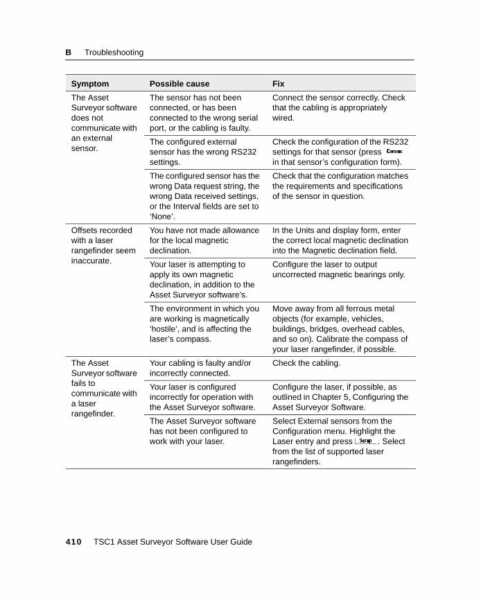
B Troubleshooting
The AssetSurveyor softwaredoes notcommunicate withan externalsensor.
The sensor has not beenconnected, or has beenconnected to the wrong serialport, or the cabling is faulty.
Connect the sensor correctly. Checkthat the cabling is appropriatelywired.
The configured externalsensor has the wrong RS232settings.
Check the configuration of the RS232settings for that sensor (pressmin that sensor’s configuration form).
The configured sensor has thewrong Data request string, thewrong Data received settings,or the Interval fields are set to‘None’.
Check that the configuration matchesthe requirements and specificationsof the sensor in question.
Offsets recordedwith a laserrangefinder seeminaccurate.
You have not made allowancefor the local magneticdeclination.
In the Units and display form, enterthe correct local magnetic declinationinto the Magnetic declination field.
Your laser is attempting toapply its own magneticdeclination, in addition to theAsset Surveyor software’s.
Configure the laser to outputuncorrected magnetic bearings only.
The environment in which youare working is magnetically‘hostile’, and is affecting thelaser’s compass.
Move away from all ferrous metalobjects (for example, vehicles,buildings, bridges, overhead cables,and so on). Calibrate the compass ofyour laser rangefinder, if possible.
The AssetSurveyor softwarefails tocommunicate witha laserrangefinder.
Your cabling is faulty and/orincorrectly connected.
Check the cabling.
Your laser is configuredincorrectly for operation withthe Asset Surveyor software.
Configure the laser, if possible, asoutlined in Chapter 5, Configuring theAsset Surveyor Software.
The Asset Surveyor softwarehas not been configured towork with your laser.
Select External sensors from theConfiguration menu. Highlight theLaser entry and pressS . Selectfrom the list of supported laserrangefinders.
Symptom Possible cause Fix
410 TSC1 Asset Surveyor Software User Guide
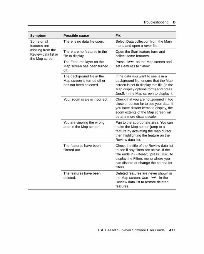
Troubleshooting B
Some or allfeatures aremissing from theReview data list orthe Map screen.
There is no data file open. Select Data collection from the Mainmenu and open a rover file.
There are no features in thefile to display.
Open the Start feature form andcollect some features.
The Features layer on theMap screen has been turnedoff.
Press& on the Map screen andset Features to ‘Show’.
The background file in theMap screen is turned off orhas not been selected.
If the data you want to see is in abackground file, ensure that the Mapscreen is set to display this file (in theMap display options form) and press1 in the Map screen to display it.
Your zoom scale is incorrect. Check that you are not zoomed in tooclose or out too far to see your data. Ifyou have distant items to display, thezoom extents of the Map screen willbe at a more distant scale.
You are viewing the wrongarea in the Map screen.
Pan to the appropriate area. You canmake the Map screen jump to afeature by activating the map cursorthen highlighting the feature on theReview data list.
The features have beenfiltered out.
Check the title of the Review data listto see if any filters are active. If thetitle ends in (Filtered), press^ todisplay the Filters menu where youcan disable or change the criteria forfilters.
The features have beendeleted.
Deleted features are never shown inthe Map screen. Useu in theReview data list to restore deletedfeatures.
Symptom Possible cause Fix
TSC1 Asset Surveyor Software User Guide 411

B Troubleshooting
412 TSC1 Asset Surveyor Software User Guide

A P P E N D I X
C
C Asset Surveyor MessagesIn this chapter:
■ Introduction
■ Messages
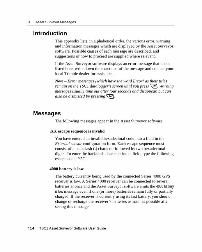
C Asset Surveyor Messages
3.1 IntroductionThis appendix lists, in alphabetical order, the various error, warningand information messages which are displayed by the Asset Surveyorsoftware. Possible causes of each message are described, andsuggestions of how to proceed are supplied where relevant.
If the Asset Surveyor software displays an error message that is notlisted here, write down the exact text of the message and contact yourlocal Trimble dealer for assistance.
Note – Error messages (which have the word Error! as their title)remain on the TSC1 datalogger’s screen until you press=. Warningmessages usually time out after four seconds and disappear, but canalso be dismissed by pressing= .
3.2 MessagesThe following messages appear in the Asset Surveyor software.
\XX escape sequence is invalid
You have entered an invalid hexadecimal code into a field in theExternal sensor configuration form. Each escape sequence mustconsist of a backslash (\) character followed by two hexadecimaldigits. To enter the backslash character into a field, type the followingescape code: ‘\5C’.
4000 battery is low
The battery currently being used by the connected Series 4000 GPSreceiver is low. A Series 4000 receiver can be connected to severalbatteries at once and the Asset Surveyor software emits the 4000 batteryis low message even if one (or more) batteries remain fully or partiallycharged. If the receiver is currently using its last battery, you shouldchange or recharge the receiver’s batteries as soon as possible afterseeing this message.
414 TSC1 Asset Surveyor Software User Guide
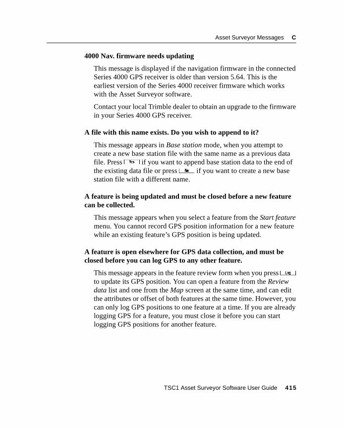
Asset Surveyor Messages C
4000 Nav. firmware needs updating
This message is displayed if the navigation firmware in the connectedSeries 4000 GPS receiver is older than version 5.64. This is theearliest version of the Series 4000 receiver firmware which workswith the Asset Surveyor software.
Contact your local Trimble dealer to obtain an upgrade to the firmwarein your Series 4000 GPS receiver.
A file with this name exists. Do you wish to append to it?
This message appears in Base station mode, when you attempt tocreate a new base station file with the same name as a previous datafile. Pressy if you want to append base station data to the end ofthe existing data file or pressn if you want to create a new basestation file with a different name.
A feature is being updated and must be closed before a new featurecan be collected.
This message appears when you select a feature from the Start featuremenu. You cannot record GPS position information for a new featurewhile an existing feature’s GPS position is being updated.
A feature is open elsewhere for GPS data collection, and must beclosed before you can log GPS to any other feature.
This message appears in the feature review form when you press3to update its GPS position. You can open a feature from the Reviewdata list and one from the Map screen at the same time, and can editthe attributes or offset of both features at the same time. However, youcan only log GPS positions to one feature at a time. If you are alreadylogging GPS for a feature, you must close it before you can startlogging GPS positions for another feature.
TSC1 Asset Surveyor Software User Guide 415
C Asset Surveyor Messages
Abandon changes?
This message warns you that changes you have made to a form will belost if you continue. It is displayed if you press= on a form afterchanging the value of one or more fields. If you want to save changesto the form, pressn , followed by\ , otherwise pressy toabandon the changes.
Abandon feature?
This message appears if you press= on the attribute entry form fora new feature in Data collection. Pressy if you want to abandonthe feature. If you want to save the feature, pressn followed by\ .
If you abandon a feature, its attributes, GPS positions, and anyassociated external sensor data are discarded by the Asset Surveyorsoftware, and cannot be recovered.
Abandon update?
This message appears if you press= on the attribute entry form foran existing feature in Data collection. Pressy if you want toabandon the changes to the feature. If you want to save the feature,pressn followed by\ .
If you abandon a feature update, any changes to its attributes, GPSpositions and any associated external sensor data are discarded by theAsset Surveyor software, and cannot be recovered.
Aborted
You have used the= key to successfully cancel a long operation.
Activation complete
This message appears when the DGPS satellite has confirmed thatyour Pro XRS receiver has the appropriate activation to receiveRTCM corrections using the integrated DGPS satellite component ofthe receiver.
416 TSC1 Asset Surveyor Software User Guide
Asset Surveyor Messages C
Almanac sent
The Asset Surveyor software displays this message to inform you thata GPS almanac has been sent to the PC.
Are you sure you want to disconnect from GPS?
This message is displayed when you select the Disconnect entry fromthe Utilities menu. Pressy if you want the Asset Surveyorsoftware to cease communicating with the currently connected GPSreceiver, or pressn if you want to continue using the GPS receiver.
When a GPS receiver is disconnected, the Asset Surveyor softwareturns the receiver off if it is able to do so. If not, you should manuallyturn off the receiver to avoid draining its batteries. If the connectedGPS receiver is a Series 4000 or Site Surveyor 4400 receiver,remember to turn the receiver back on before attempting to re-establish communications with the Asset Surveyor software.
Battery is low
The level of the internal lithium-ion battery is very low. You shouldrecharge or replace this battery immediately. Data may becomecorrupted if the battery is allowed to run completely dead while theTSC1 datalogger is in use.
Battery level is low. Data may become corrupted if battery is allowedto run dead
The level of the internal lithium-ion battery is very low. You shouldrecharge or replace this battery immediately. Data may becomecorrupted if the battery is allowed to run completely dead while theTSC1 datalogger is in use.
TSC1 Asset Surveyor Software User Guide 417
C Asset Surveyor Messages
Best results are obtained by using a receiver with 12 channels
If you start a base station file with an 8-channel Pro XL or Pro XRreceiver connected, the Asset Surveyor software warns you that youobtain better results using a 12-channel receiver. If you want toupgrade an 8-channel Pro XL or Pro XR to 12 channels, contact yourlocal Trimble dealer for up-to-date pricing details.
Building list . . . .
The Asset Surveyor software displays this message when a newfeature has been opened and a list of attributes is being built for thatfeature.
Cannot delete current Start/Target
You cannot delete a waypoint while it is selected as the Start or Target.Select a different waypoint or feature as the Start or Target.
Cannot open more than two features simultaneously.
You have tried to open a new feature and an existing feature from thedata file as well as a feature from the Map screen. Only two featurescan be open for editing at the same time.
Cannot perform this operation because the file is already open in theMap.
This message appears when you try to open, move, or delete a filewhich is in use as the background file in the Map module. Exit theMap module or change the background file.
Cannot perform this operation because the file is not a rover file
This message appears when you try to open a file for data collectionwhich is not a rover file.
418 TSC1 Asset Surveyor Software User Guide
Asset Surveyor Messages C
Cannot perform this operation because the file is open for datacollection.
This message appears when you try to open, move, or delete a filewhich is open. Close the file first.
Cannot quickmark when logging is paused
This message is displayed if you pressq to record a quickmarkwhen logging is paused. The quickmark is not recorded. You mustreturn to the position of the feature you tried to quickmark and re-record the feature after resuming logging of GPS positions.
If you want to record a point feature which lies off a line feature or offthe perimeter of an area feature, you cannot record the feature as aquickmark (without inserting a spike in the line or area feature), unlessyou use an offset. It is usually easiest to use theN softkey to recordpoint features lying off a line or area feature.
Cannot segment the line when logging is paused
This message is displayed if you presss to segment a line whenlogging is paused. To segment a line, the Asset Surveyor softwaremust record a GPS position. PressL to resume logging, then presss .
Cannot specify units in a unitless domain
This message is displayed if you type any non-numeric characters(apart from sign characters) into a numeric field which does not permitunits to be specified.
Carrier lost hh:mm
This message appears on the status line when the receiver has lost lockon the minimum number of satellites required for carrier phase datacollection. The time displayed shows the amount of carrier data thathad been logged since the previous loss of carrier information.
TSC1 Asset Surveyor Software User Guide 419
C Asset Surveyor Messages
Carrier mode is off
This message appears on the GPS status line when you start a file andcarrier phase mode is disabled.
Carrier mode is on
This message appears on the GPS status line when you start a file andcarrier phase mode is enabled.
Carrier mode should be left on if further features will require carrierprecision. Are you sure you want to turn Carrier mode off?
The Asset Surveyor software displays this message to remind you thatCarrier mode should be left set to ‘On’ if further features requirecarrier precision.
Carrier phase data collection works best when in Overdetermined 3Dmode.
This message is displayed by the Asset Surveyor software when a filehas been opened with carrier phase enabled and the Position mode inPosition filters is set to anything other than ‘Overdetermined. 3D’.Trimble recommends that Position mode be set to ‘Overdetermined.3D’ for best results when using carrier phase.
Carrier started
This message appears on the GPS status line when a complete carrierphase message is received after the carrier time has been reset.
hh:mm Carrier time
This message displays whenever carrier data is logged and informsyou of the amount of carrier data that has been logged since the lasttime this counter was reset due to a loss on satellite lock.
420 TSC1 Asset Surveyor Software User Guide
Asset Surveyor Messages C
Check antenna/cable
The Asset Surveyor software displays this message in the status barwhenever the GPS receiver detects that the antenna cable isdisconnected or faulty. Connect the antenna cable or replace it if it isfaulty.
Check “Real-time input options” for other serial parameters.
This message is displayed to remind you to check the serial parametersettings (Baud rate, Data bits, Stop bits and Parity) in the Real-timeinput options form. These settings should match those that you haveset in the NMEA/TSIP output options form, for configuration to takeeffect.
Checking activation
This message appears on the status line when you have configured thePro XRS receiver to receive RTCM corrections using the DGPSsatellite component of the receiver. It may take up to ten minutes forthe DGPS satellite component to receive confirmation from thesatellite that your receiver is activated to receive these corrections.
Checking initialization
The Asset Surveyor software displays this message in the status barwhen the receiver is checking the validity of the RTK (Real-TimeKinematic) solution that has been computed.
Clear waypoints file, deleting all current waypoints?
TheD softkey on the Review waypoint menu deletes all waypointsstored on the TSC1 datalogger. This message is displayed when youpressD to avoid the accidental deletion of all waypoints. Pressy to actually delete the waypoints orn to return to the menu ofwaypoints.
TSC1 Asset Surveyor Software User Guide 421
C Asset Surveyor Messages
Code accepted!
You have entered a valid DGPS activation code. The DGPS service isnow activated.
Code less than <X> digits. Please try again.
The DGPS activation code you have entered does not contain enoughdigits. Enter the code again.
Communications error
This error message indicates a break-down in communicationsbetween the Asset Surveyor software and an external sensor. This maybe caused by incorrect or damaged wiring in the cable between theAsset Surveyor software and the sensor, or the sensor operating in anincorrect mode. Check that the communications parameters (under them softkey, from the external sensor configuration form) are setcorrectly.
This message may also appear if an external sensor emits data at sucha rate that the TSC1 datalogger cannot process the incoming data fastenough to avoid a serial buffer overrun. In this situation, part or all ofan incoming data record may be lost. If it is critical that the dataloggerbe able to log every record emitted by the sensor, it may be necessaryto run the sensor at a slower rate.
Configuration file has been reset to factory default settings
All settings in the Asset Surveyor software have been returned to theirdefault settings. When you clear this message the Asset Surveyorsoftware restarts.
422 TSC1 Asset Surveyor Software User Guide
Asset Surveyor Messages C
Confirm deletion
Whenever you attempt to delete a data file, data dictionary, waypoint,coordinate system, datum, zone or language file, the Asset Surveyorsoftware asks you to confirm that it really is your intention to deletethe indicated item. Pressy to delete the item orn to indicatethat you either selected the delete operation by mistake, or havedecided not to delete the item.
Connect antenna/cable
This message appears on the GPS status line if the Asset Surveyorsoftware detects that the receiver’s antenna and/or cable isdisconnected, improperly connected, or faulty.
Connect cable to PC
This message is displayed when you select File transfer from theAsset Surveyor software’s File manager menu. It serves as a reminderto connect the TSC1 datalogger to the PC before attempting to transferfiles between the two using the GPS Pathfinder Office software.
Connecting to GPS
The Asset Surveyor software displays this message on the status lineto indicate that it is attempting to communicate with a GPS receiver.You can press= to cancel an attempt at connection, or wait for theconnection attempt to conclude.
Constant offset(s) are active
Whenever you create a new rover file or reopen an existing file, theAsset Surveyor software checks to see if you had previouslyconfigured one or more constant offsets. If you had, the AssetSurveyor software warns you by displaying the Constant offset(s) areactive message. If you do not want to apply constant offsets to featureswhich you record, select Constant offset from the Configuration menuandK all of the configured offsets to zero.
TSC1 Asset Surveyor Software User Guide 423
C Asset Surveyor Messages
Copy failed
This message is displayed when an attempt to copy file(s) from theTSC1 datalogger to the PC card (or vice versa) has failed. In mostcases this happens because there is insufficient memory in the PC cardor datalogger.
Data dictionary cannot be deleted until files using it are deleted first
When you pressd on the menu of data dictionaries, the AssetSurveyor software checks that there are no data files on the TSC1datalogger that are associated with this data dictionary. If one or moredata files require(s) this data dictionary, the above message appearsand you cannot delete this dictionary. You must transfer the data filesconcerned to the GPS Pathfinder Office software and then delete thesedata files from the TSC1 datalogger before you are permitted to deletethis data dictionary. The Open existing file screen shows which datadictionary is used by the selected data file.
Data dictionary read OK
This message is displayed on the File transfer status form when a datadictionary has been transferred from the GPS Pathfinder Officesoftware to the TSC1 datalogger, and the Asset Surveyor software hasverified that the data dictionary was transferred correctly andsuccessfully stored on the TSC1 datalogger.
Deleted file
The Asset Surveyor software displays this message after it hassuccessfully deleted a file.
Directory sent
This message appears on the File transfer status form, and indicatesthat the Asset Surveyor software has transmitted a directory of datafiles to Pathfinder Office.
424 TSC1 Asset Surveyor Software User Guide
Asset Surveyor Messages C
Disconnect GPS before selecting this option
This message is displayed if you select the File transfer entry whenthe GPS receiver is still connected to (and communicating with) theAsset Surveyor software. You must disconnect the GPS receiverbefore attempting to perform this operation, as the Asset Surveyorsoftware does not allow file transfer and data collection to beperformed simultaneously. Select Disconnect GPS from the Utilitiesmenu, or simply unplug the GPS receiver and wait until the AssetSurveyor software detects that the receiver is no longer present.
Do you have a <X>-digit activation code to enter?
This message appears when you try to configure certain DGPSservices.
Do you want to copy all data files to the datalogger?
The Asset Surveyor software displays this message when you havepressed the0 softkey on the PC card:Copy file(s) menu, indicatingthat you want to copy all of the files on the PC card to the TSC1datalogger. Pressy to confirm this, or pressn to abandon theoperation.
Do you want to copy all data files to the PC card?
The Asset Surveyor software displays this message when you havepressed the0 softkey on the TSC1:Copy file(s) menu, indicatingthat you want to copy all of the files on the TSC1 datalogger to the PCcard. Pressy to confirm this, or pressn to abandon theoperation.
Do you want to move all data files to the datalogger?
The Asset Surveyor software displays this message when you havepressed the0 softkey on the PC card:Move file(s) menu,indicating that you want to move all of the files on the PC card to theTSC1 datalogger. Pressy to confirm this, or pressn toabandon the operation.
TSC1 Asset Surveyor Software User Guide 425
C Asset Surveyor Messages
Do you want to move all data files to the PC card?
The Asset Surveyor software displays this message when you havepressed the0 softkey on the TSC1:Move file(s) menu, indicatingthat you want to move all of the files on the TSC1 datalogger to the PCcard. Pressy to confirm this, or pressn to abandon theoperation.
Do you want to delete ALL files?
When you pressD on the Delete file menu, the Asset Surveyorsoftware asks you to confirm that you want to delete all of the filesdisplayed. You are asked to reconfirm deletion for any file(s) whichhave not yet been transferred to the PC.
Do you want to store this feature now?
The minimum number of GPS positions for this feature have not beenrecorded. The Asset Surveyor software asks you to confirm that youwant to stop logging and store the feature. Pressy to store thefeature orn to continue logging.
Doing fixes
This message appears in the Status field of the Receiver status formwhen connected to a GPS receiver which is currently computing GPSpositions (that is, is tracking sufficient satellites, with a PDOP lowerthan the configured mask).
Downloading file
This message is displayed during the first stage of the upgradeprocedure, when upgrading the TSC1 datalogger to a new version ofthe Asset Surveyor software.
426 TSC1 Asset Surveyor Software User Guide
Asset Surveyor Messages C
Duplicate data dictionary name not allowed
The Asset Surveyor software has just received a new data dictionaryfrom the GPS Pathfinder Office software. However, the datadictionary name is identical to the name of an existing data dictionaryon the TSC1 datalogger. Delete the old data dictionary from the TSC1datalogger, then transfer the new data dictionary.
Duplicate filename. Do you wish to overwrite?
You have attempted to move or copy a file to the PC card or the TSC1datalogger and a file with the same name already resides there. Pressy if you want to overwrite the existing file, or pressn toabandon the operation.
Duplicate file names are not allowed
The Asset Surveyor software insists that all data files have uniquenames. This message is displayed if you attempt to create a new roverdata file with the same name as an existing data file. The case (upperor lower) of a letter in a file’s name is ignored when comparing twonames for equivalence.
Entry required
If, when you create a data dictionary in the GPS Pathfinder Officesoftware, you specify Entry required for an attribute of a feature, theAsset Surveyor software does not let you save a feature of that typewithout entering a value for that attribute. If you press \ on anattribute entry form when one or more attributes with the Entryrequired flag still have the null value, the Asset Surveyor softwaredisplays this error message and directs you to the first attributerequiring an entry.
Error!
An error has occurred. Specific details will follow.
TSC1 Asset Surveyor Software User Guide 427
C Asset Surveyor Messages
Error opening data dictionary
The Asset Surveyor software is unable to open a data dictionary foruse in association with a particular data file. Try deleting thatdictionary and transferring it from the GPS Pathfinder Office softwareto the TSC1 datalogger again.
It is also possible that there is too little data storage space remainingon the TSC1 datalogger to open and cache the data dictionary. In thiscase, try deleting one or more unwanted data files. If the problempersists, contact your local Trimble dealer for assistance.
Existing offset reset
The offset stored for the current feature has been reset to the defaultvalue because you have started to log new GPS data for the feature.
Exit Data collection?
This message is displayed whenever you press= to exit the rover orbase file currently open. Pressy to exit, or pressn to cancelexiting.
Exit data file and disconnect GPS before selecting File transfer
You must close any open data file and disconnect from the GPSreceiver before transferring files to or from your PC.
Exit data file before selecting File transfer
You must close any open rover, background, or data dictionary filebefore transferring files to or from your PC.
External battery is low
The external (GPS receiver) battery is low. You should complete yourcurrent operation as quickly as is practical, and then change the GPSreceiver’s batteries before reconnecting to GPS.
428 TSC1 Asset Surveyor Software User Guide
Asset Surveyor Messages C
External sensor data cannot be recorded with more than one featureopen.
The software has received external sensor input while two features areopen, and is unable to determine which feature to apply this data to.Close the feature for which you do not want to record external sensorinput, then send the external sensor data again.
Failed to load coordinate system
Error message that is displayed when a coordinate system fails to load,usually because there is insufficient memory available for thecoordinate system in question.
File cannot be closed while this feature is open.
You cannot close a data file while a feature is open for editing or GPSupdate. Close the feature before closing the file.
File error
An error has occurred while the Asset Surveyor software wasperforming a file-related operation (reading, writing, or creating a file,for example).
This message may occur when the Asset Surveyor software attemptsto write to a data file and the TSC1 datalogger’s data storage memoryis full. In this case, you should press any key to restart the AssetSurveyor software and then transfer and delete sufficient data filesbefore continuing to collect data.
File is not available for background map display
The file you have selected as the background file in the Map modulecould not be found. The selected background file is set to ‘None’instead.
File received
The Asset Surveyor software displays this message when a file hasbeen successfully received from the PC.
TSC1 Asset Surveyor Software User Guide 429
C Asset Surveyor Messages
File sent
The Asset Surveyor software displays this message when it hassuccessfully transferred a file to the PC.
Floating point number too large
A numeric value which you have entered into a field is too large to bestored or displayed by the Asset Surveyor software.
The Asset Surveyor software can store and display large numericvalues, so when this message is displayed, it usually means that youhave just typed a value incorrectly, or possibly that you have entered acoordinate using an inappropriate coordinate system (which cannotmathematically represent the point entered).
GPS in 2D mode
This message is displayed when a GPS receiver is connected andoperating in the ‘Auto 2D/3D’ Position mode, and the receiverswitches from computing 3D GPS positions to computing 2D GPSpositions.
GPS Update has been prohibited
The Allow GPS update field in Configuration / GPS rover options /Logging options has been set to ‘Never’ to prevent GPS update. Set itto ‘Always’ or ‘Warn first’.
Heading locked
This message flashes in the status line in the Navigation screen whenyour velocity is too low for the Asset Surveyor software to compute aheading. Start moving, or move faster, to unlock the heading.
Heading unavailable
This message flashes in the status line in the Navigation module whenthe Asset Surveyor software cannot compute a heading. Start movingto acquire a heading.
430 TSC1 Asset Surveyor Software User Guide
Asset Surveyor Messages C
High RMS
The Asset Surveyor software displays this message in the status linewhen initializing an RTK solution. RMS is an indicator of the qualityof the GPS phase measurements. High RMS indicates that there is highmultipath or the initialization may be bad, lost, or not yet gained.
ID sent
The Asset Surveyor software displays this message when it hassuccessfully sent its unique ID to the GPS Pathfinder Office software.
Inappropriate location for map projection
You have entered a coordinate (North/East) which is outside thebounds of the currently selected coordinate system zone. Check thatyou have selected the appropriate coordinate system and zone. Checkthat you have entered the coordinate correctly (paying particularattention to signed values). If you are using a custom coordinatesystem and/or zone, check that you have defined the coordinatesystem, datum and/or zone correctly.
Initialize in hh:mm
This message is displayed in the status bar to indicate the expectedtime to go until the receiver initializes for an RTK (Real-timeKinematic) solution.
Initialized
This message is displayed in the status bar to indicate that the receiverhas initialized a valid RTK (Real-time Kinematic) solution.
Initializing, please wait
This message is displayed in the status bar to inform you that thereceiver is attempting to initialize an RTK solution.
TSC1 Asset Surveyor Software User Guide 431
C Asset Surveyor Messages
Insufficient carrier data; do you want to close this file now?
This question appears if you attempt to close a data file (which islogging carrier phase data), and the last feature(s) have been collectedin a carrier data block which has not surpassed the configuredMinimum time. Pressy to close the file, or pressn and waituntil the Asset Surveyor software has recorded enough carrier-phasedata before attempting to close the file again.
Insufficient GPS positions: do you want to store this feature now?
You have pressed\ to store the details for the current point featurebefore the Asset Surveyor software has had time to record the required(Minimum positions) number of GPS positions. Pressy to storethe point feature, or pressn and wait until the Asset Surveyorsoftware has recorded enough positions before pressing\ again.
Insufficient space to rebuild coordinate system index
The coordinate system index has failed to rebuild due to insufficientmemory. You should transfer any data files on the TSC1 datalogger toa PC card or back to your office PC to free up memory so that theindex can be rebuilt.
Insufficient SVs
The receiver is not tracking enough satellites to compute a GPSposition.
Internal battery is dead
The internal battery in the TSC1 datalogger is dead. Replace thelithium-ion battery or attach the TSC1 datalogger to a charger. Youcan continue to use the TSC1 if you are connected to a GPS receiverthat can power the TSC1 datalogger.
432 TSC1 Asset Surveyor Software User Guide
Asset Surveyor Messages C
Internal battery is low
The internal battery in the TSC1 datalogger is low. Replace thelithium-ion battery or attach the datalogger to a charger. You cancontinue to use the TSC1 datalogger if you are connected to a GPSreceiver that can power the TSC1.
Invalid activation code. Please try again or contact your serviceprovider
This error message is displayed if you have entered an invalidactivation code for your chosen DGPS service. Try again, and if theproblem persists, contact your service provider.
Invalid date
The date you have entered is invalid. Check that you have entered thedate in the correct format (subject to the Date format field in the Timeand date configuration form).
Invalid file or version
A file on your TSC1 datalogger has an invalid version number. Becareful not to mix files from different versions of the Asset Surveyorsoftware. If the problem persists, contact your local Trimble dealer forassistance.
Invalid time
The time you have entered is invalid. Remember to enter the time asup to three values separated by a space or a colon. You can enter timesin either the 12- or 24-hour clock format. If you are entering timesusing the 12-hour clock, remember to specify ‘pm’ if the time is aftermidday. You can configure the way in which times are displayed in theTime and date configuration form.
TSC1 Asset Surveyor Software User Guide 433
C Asset Surveyor Messages
Invalid units
The unit you have entered is not permitted in the context of the fieldinto which it was typed. Specify the correct units (by pressing thei softkey if necessary).
If you type an alphabetic character into a numeric field by mistake, theAsset Surveyor software mistakes it for a units designator. Edit thefield and remove the spurious alphabetic character.
(filename) is open in Data collection and cannot be copied
The file you have attempted to copy to the TSC1 datalogger or PCcard is currently open in Data collection and cannot be copied. PresstheN key to cycle to Data collection and press= to exit the file.You may then proceed with the copy operation.
(filename) is open in Data collection and cannot be deleted
The file you have attempted to delete is currently open in Datacollection and cannot be deleted. Press theN key to cycle to Datacollection and press= to exit the file. You may then proceed withthe delete operation.
(filename) is open in Data collection and cannot be moved
The file you have attempted to move to the TSC1 datalogger or PCcard is currently open in Data collection and cannot be moved. PresstheN key to cycle to Data collection and press= to exit the file.You may then proceed with the move operation.
(filename) is open in Data collection and cannot be renamed
The file you have attempted to rename is currently open in Datacollection and cannot be renamed. Press theN key to cycle to Datacollection and press= to exit the file. You may then proceed withthe rename operation.
434 TSC1 Asset Surveyor Software User Guide
Asset Surveyor Messages C
Laser offsets can only be recorded for features
You attempted to record a laser offset when you were not logging afeature. The Asset Surveyor software only associates offsets withfeatures, so you must start a feature before recording a laser offset.
Less than 5 L2 SVs
The Asset Surveyor software displays this message when attemptingto initialize an RTK (Real-time Kinematic) solution. This messageindicates that the receiver is tracking an insufficient number (less thanfive) L2 signal satellites. There may be a large obstruction in the lineof sight or more satellites may be low on the horizon.
Logging paused
When you press thep softkey while logging GPS positions for apoint, line, or area feature, the Asset Surveyor software displays thismessage on the GPS status line. The message continues to flash on thestatus line until you resume logging by pressing theL softkey.
Maximum bytes includes the length of the prefix and suffix
The Max bytes record length you have specified while configuring anexternal sensor is less than the combined length of the prefix andsuffix strings. Remember that the maximum record length includes thelength of the prefix and suffix strings.
Memory nearly full
This warning message is displayed once a minute whenever there isless than 20 kb of data storage space left. If you are currently loggingdata, free up some space by deleting old data files. You can select afile in the Open existing file form to determine how much space a datafile is using.
Minimum time achieved!
This message is displayed on the status line when the Minimum timefor carrier phase data has been exceeded.
TSC1 Asset Surveyor Software User Guide 435
C Asset Surveyor Messages
Move failed
This message is displayed when an attempt to move file(s) from theTSC1 datalogger to the PC card (or vice versa) has failed. In mostcases this happens because there is insufficient memory in thedatalogger of PC card.
Navigation firmware needs updating
The firmware on your Series 4000 receiver is too old to work with thisversion of the Asset Surveyor software.
No almanac file available
This message is displayed on the TSC1 datalogger if you try totransfer an almanac file from the datalogger to the GPS PathfinderOffice software, and no almanac file exists on the TSC1 datalogger.The Asset Surveyor software records an almanac from any PathfinderGPS receiver which has an up-to-date almanac. If you have a Series4000, Site Surveyor 4400, or GPS Total Station 4800 receiver, theAsset Surveyor software does not record an almanac from the receiver,but you can record an almanac by logging data to the receiver’sinternal memory and then extracting it as described in the GISSurveyor Operation Manual.
No features found
If you log data to a file whose associated data dictionary contains nofeatures at all, this message is displayed. You can still log GPSpositions and external sensor data from external sensors without anyassociated feature or attribute information.
This message is also displayed if you attempt to review a file whichdoes not contain any features (for example, a base station file).
No files
This message is displayed in place of the menu of available data fileswhen the TSC1 datalogger does not contain any data files.
436 TSC1 Asset Surveyor Software User Guide
Asset Surveyor Messages C
No GPS
This message appears on the status line in the Navigation modulewhen you are not connected to the GPS receiver.
No GPS detected. Check cabling, batteries etc. Do you wish to retryGPS now?
You have either just turned the TSC1 datalogger on, or have selected aGPS-related entry from the Main menu (such as Satellite information,or Receiver status), and have not connected, powered or turned onyour GPS receiver. If you do not want to use GPS, pressn . If youwant to use GPS, check that the receiver is connected to the TSC1datalogger, that the receiver is connected to its batteries (which mustbe charged) and that the receiver is turned on (if it has an externalpower button) before pressingy to retry the GPS connection.
If the Asset Surveyor software again fails to communicate with theGPS receiver, you may have a faulty cable, battery pack or receiver.Contact your local Trimble dealer to have your GPS equipmentserviced.
No GPS positions for feature
This message is displayed when you press theQ softkey in Reviewfile and the currently highlighted feature has no recorded GPSpositions.
No GPS positions recorded. Do you want to store this feature now?
You have pressed\ on an attribute entry form while connected to aGPS receiver, but no GPS positions have been logged for the currentfeature. The GPS receiver only logs positions if there are sufficientsatellites and the PDOP is low enough. You should pressn andreturn to the attribute entry form before letting the GPS receiverrecord GPS positions for that feature. If you pressy, the AssetSurveyor software saves the attributes you have entered for thefeature, but the GPS Pathfinder Office software ignores the featureentirely (unless you can process the resulting data in such a way as toassign a position to that feature).
TSC1 Asset Surveyor Software User Guide 437
C Asset Surveyor Messages
No GPS time
The GPS receiver has not yet obtained GPS time from a GPS satellite.
No more files permitted
You have reached the maximum limit on the number of data files, datadictionaries, and language files permitted on the TSC1 datalogger.Transfer your data files to the PC and delete from the TSC1 dataloggerany that are not needed.
No Target
This message is displayed whenever you are in a navigation form andhave not selected a Target to navigate to. To select a Target pressGand choose from the menu of defined waypoints.
No usable SVs
This message appears in the Status field of the Receiver status formwhen connected to a GPS receiver and the receiver is tracking no GPSsatellites. In this situation, the receiver is unable to compute a GPSposition. The GPS receiver may have an old, inaccurate or missingalmanac, or the receiver’s antenna may be obscured.
Not found
The Asset Surveyor software displays this message when an itemsearch in file review has failed to find the specified item.
Offset received
The Asset Surveyor software has received and decoded an offsetmeasurement from a laser rangefinder.
OLD Navigation
The title of the Navigation form displays OLD Navigation whenever acurrent GPS position is unavailable (for example, when there are toofew satellites, the PDOP is too high, or the radio link is down).
438 TSC1 Asset Surveyor Software User Guide
Asset Surveyor Messages C
OLD Position
The title of the GPS Position form changes to OLD Position whenevera current GPS position is unavailable (for example,. when there aretoo few satellites, the PDOP is too high, or the radio link is down).
Other windows must be closed before resetting to factory defaults
The Asset Surveyor software displays this message to advise you thatany open windows must be closed before you can reset the TSC1datalogger to factory defaults. Use theN key to cycle to the nextopen window and press the= key to close that window. Repeat untilall windows are closed and proceed with the factory defaults reset.
Out of range
The value you have entered is outside the permitted range of valuesallowed for this field. Most numeric fields have tight bounds on therange of values that may be entered. The bounds on numeric attributevalues are specified when a data dictionary is created using the GPSPathfinder Office software.
PC card error
Message advising you that an error has occurred with the inserted PCcard. Transfer any files on the PC card to your PC and reformat thecard.
PC card hardware error
This message is displayed when the Asset Surveyor software detects aproblem with the inserted PC card. Try reinserting the card. If theproblem persists the card may need reformatted or replaced.
PC card memory nearly full
This warning message indicates that the memory on the inserted PCcard is nearly full. You should transfer the data on the PC card to theGPS Pathfinder Office software before attempting to log further datato the card.
TSC1 Asset Surveyor Software User Guide 439
C Asset Surveyor Messages
PC card stuck, please wait or reinsert
This message is displayed when the Asset Surveyor software is notcommunicating properly with the inserted PC card. Wait for it toestablish communications or reinsert the PC card.
PDOP is too high
The current PDOP is higher than the configured PDOP mask, and theGPS receiver is no longer computing GPS positions. For a discussionof the effect of satellite geometry on the accuracy of GPS positions,refer to the Mapping Systems General Reference manual.
Please charge the internal battery before upgrading
The Asset Surveyor software displays this message if you attempt toupgrade the software using the TSC1 datalogger’s internal lithium-ionbattery, and the battery level is below 50%. Recharge the batterybefore proceeding with the upgrade.
Please configure the current time and date
The Asset Surveyor software displays this message every five minutesif the TSC1 datalogger’s internal clock is set to a time or date which isknown to be incorrect because it is set prior to the release date of theAsset Surveyor software. You can reset the TSC1 datalogger’s internaltime and date in the Time and date configuration form.
Please delete all files before upgrading
You have attempted to upgrade the TSC1 datalogger and there are filesstill on the datalogger that must be transferred and/or deleted beforethe upgrade can commence.
Please exit Data collection before resetting receiver
This message appears when you attempt to reset the GPS receiverwhile Data collection is open. Exit Data collection before selectingthe Reset GPS receiver entry in Utilities.
440 TSC1 Asset Surveyor Software User Guide
Asset Surveyor Messages C
Please exit data file and disconnect GPS before commencing upgrade
This message appears when you attempt to upgrade the software onthe TSC1 datalogger and the TSC1 is connected to GPS with a datafile open. Exit the data file and disconnect from GPS (use theDisconnect GPS entry in Utilities) before attempting to upgrade theTSC1 datalogger.
Please wait . . . Processing
The Asset Surveyor software displays this message whenever it isbusy performing a long operation.
Poor ratio
The Asset Surveyor software displays this message in the status linewhen it is attempting to initialize a fixed RTK (Real-time Kinematic)solution. During initialization, an RTK-capable receiver determinesthe integer number of wavelengths for each satellite and for anyparticular set of integers it calculates a ratio, or probability, that it isthe correct set, by comparing it to the next best integer set. A highratio gives the user confidence that the integer set used to provide anRTK solution is much better than any other set. The Poor ratio messageindicates that the integer solution currently being computed is notgood enough to provide a fixed RTK solution.
Port is currently in use. Check all communication settings
This message is displayed when you attempt to use a serial port on theTSC1 datalogger that is already in use elsewhere in the AssetSurveyor software. Check all communication settings.
Position is out of the current coordinate systems boundaries
This message is displayed when you receive a position from the GPSreceiver that is outside the boundaries of the currently selectedcoordinate system. Check that the selected coordinate system inConfiguration / Coordinate system is appropriate for your currentlocation.
TSC1 Asset Surveyor Software User Guide 441
C Asset Surveyor Messages
Press OFFSET before using the laser
You attempted to record a laser offset while logging a line or areafeature. The Asset Surveyor software requires you to be viewing theoffset form for this feature are the time you record the laser offset (sothat it can be sure that you remember to enter a value into theDirection field). The offset form is accessible by pressingO .
Processing
This message appears when the Asset Surveyor software isperforming a processing operation which may take some time. Press= to cancel.
Quickmark: <feature>
This message appears in the status line when a quickmarked feature isstored. It indicates the feature type you have quickmarked.
Quickmark position outside five second limit
When you pressQ to review the position of a quickmark feature,the Asset Surveyor software displays the above message if the GPSpositions which bracket the quickmark feature are not within 5seconds of the quickmark. This occurs because GPS positions wereunavailable just after the quickmark was recorded (for example, due toinsufficient satellites, high PDOP or radio link loss).
Radio link down
Real-time (RTCM or RTK) corrections are not being received by theGPS receiver, or have not been received for a period in excess of theconfigured real-time Age limit. Check that the telemetry link is stillattached to the GPS receiver, is turned on, and is still being powered.It is possible that the telemetry link has been obstructed (for example,by a hill, a building or other physical obstructions), that the base GPSreceiver or transmitter have ceased operating, or that your roving GPSreceiver is using one or more satellites which are not visible to thebase receiver.
442 TSC1 Asset Surveyor Software User Guide
Asset Surveyor Messages C
Recording almanac
The Asset Surveyor software is currently recording an up-to-datealmanac from the connected Pathfinder GPS receiver. The almanaccontains satellite orbital information which can be sent to the receiverat a later date to make sure rapid acquisition of satellites, and can alsobe transferred to the PC for use in mission planning.
Recording ephemeris
The Asset Surveyor software is recording the most up to date satelliteinformation for a particular satellite (which has either just beenacquired by the receiver, or has just transmitted updated ephemerisinformation). The Asset Surveyor software briefly stops recordingGPS positions while it receives and logs the up-to-date ephemerisinformation. This information is crucial to high-accuracy differentialcorrection.
When you start logging data to a file, the Asset Surveyor softwarerecords ephemeris information for all visible satellites. This takes afew seconds, after which GPS positions can be logged.
Reset GPS receiver?
The Asset Surveyor software displays this message when you selectthe Reset receiver entry from the Utilities menu. Pressy to resetthe GPS receiver to its default settings.
Reset to factory defaults
The Asset Surveyor software displays this message when you selectthe Factory defaults entry from the Utilities menu. Pressy to resetthe Asset Surveyor software to the default configuration it wasshipped with.
RTK=Fixed
A fixed RTK solution has been computed.
TSC1 Asset Surveyor Software User Guide 443
C Asset Surveyor Messages
RTK=Float
A float RTK solution has been computed.
Search aborted
You have interrupted a search in the Review data list by pressing=.
Searching...
The Asset Surveyor software is searching through a data file for aparticular feature or attribute value.
Sending almanac
This message appears on the status line when the Asset Surveyorsoftware loads a pre-recorded almanac into a GPS receiver, to makesure that the receiver acquires satellites quickly.
Sensor data can only be recorded while viewing an open feature
You have activated an external sensor while there is no open feature.Sensor data must be stored into an attribute field of an open feature.
Sorry, GPS time required before creating a data file
Before the Asset Surveyor software lets you create a data file for thefirst time (since installation or since you last reset the memory of yourdatalogger), it must align the datalogger’s clock with GPS time. Youshould connect your GPS receiver and let the Asset Surveyor softwarerecord a GPS time before again attempting to create a new data file.
Sorting
This message appears while the Asset Surveyor software sorts a datafile.
444 TSC1 Asset Surveyor Software User Guide
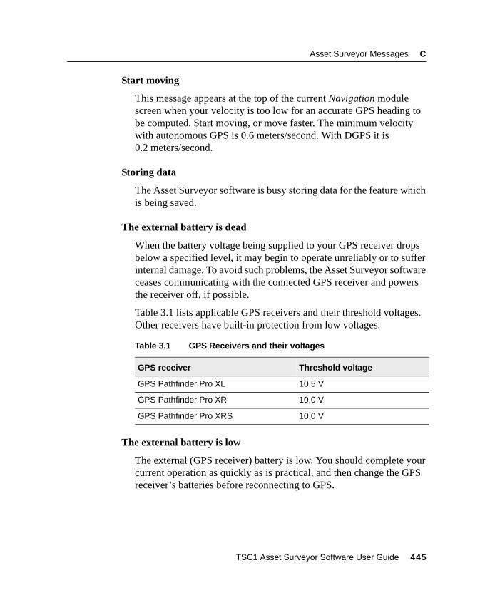
Asset Surveyor Messages C
Start moving
This message appears at the top of the current Navigation modulescreen when your velocity is too low for an accurate GPS heading tobe computed. Start moving, or move faster. The minimum velocitywith autonomous GPS is 0.6 meters/second. With DGPS it is0.2 meters/second.
Storing data
The Asset Surveyor software is busy storing data for the feature whichis being saved.
The external battery is dead
When the battery voltage being supplied to your GPS receiver dropsbelow a specified level, it may begin to operate unreliably or to sufferinternal damage. To avoid such problems, the Asset Surveyor softwareceases communicating with the connected GPS receiver and powersthe receiver off, if possible.
Table 3.1 lists applicable GPS receivers and their threshold voltages.Other receivers have built-in protection from low voltages.
The external battery is low
The external (GPS receiver) battery is low. You should complete yourcurrent operation as quickly as is practical, and then change the GPSreceiver’s batteries before reconnecting to GPS.
Table 3.1 GPS Receivers and their voltages
GPS receiver Threshold voltage
GPS Pathfinder Pro XL 10.5 V
GPS Pathfinder Pro XR 10.0 V
GPS Pathfinder Pro XRS 10.0 V
TSC1 Asset Surveyor Software User Guide 445
C Asset Surveyor Messages
The file cannot be filtered by attribute and feature type at the sametime.
You have attempted to enable both the attribute and feature filter.Either the attribute filter or the feature filter can be active, but not bothat the same time.
The geoid model you have selected may not give the accuracies thatyou require
This message is displayed to remind you that the selected geoid modelmay not provide the required accuracy.
The internal battery is low
This warning message is displayed every minute when the power inthe TSC1 battery is getting low. The battery should be replaced orrecharged as soon as possible so that the Asset Surveyor software maycontinue to be used.
The Minimum time has not yet been achieved. Are you sure you wantto turn Carrier mode off?
This message is displayed to remind you that the configured Minimumtime has not yet been achieved and that features collected since thelast loss of carrier lock may not meet your desired accuracyrequirements if the logging of carrier is discontinued.
The start time is later than the end time
You have selected a start time for your time filter that is later than theend time. The start time cannot be later.
This feature has not yet been collected
This message is displayed when you try to repeat a feature in Datacollection and a feature of that type has not yet been recorded to thecurrent data file.
446 TSC1 Asset Surveyor Software User Guide
Asset Surveyor Messages C
This feature is already open elsewhere.
This message is displayed when you try to open a feature from theMap screen or the Review data list, and the feature is already open inthe other module.
This file has not been transmitted to the PC
When you select a file from the Delete file(s) menu, the AssetSurveyor software checks that the file has been output to the GPSPathfinder Office software. If not, it displays the above message. Pressy to delete the file if you really do not want to output it to the PC.
This PC card is not supported
This error message is displayed when the Asset Surveyor software hasfailed to recognize the inserted PC card as a supported card. Try re-inserting the card, or replace the card with one that is supported by theAsset Surveyor software.
This PC card needs formatting
This error message is displayed when the Asset Surveyor software hasdetected a PC card which must be formatted before it is readable.
This receiver can not output the configured RTK record type
This message is displayed when real-time output has not been enabledfor the connected GPS receiver. The receiver is unable to output RTKmessages until real-time output is enabled.
This receiver does not connect. It is not supported by Asset Surveyor
This message appears when you try to connect to a receiver that is notsupported by the Asset Surveyor software.
This unit is not licensed for Asset Surveyor. Entering monitor mode.
You have attempted to run an unlicensed copy of the Asset Surveyorsoftware.
TSC1 Asset Surveyor Software User Guide 447
C Asset Surveyor Messages
Timed out
Communications with an external sensor or GPS receiver has timedout unexpectedly. This occurs when the Asset Surveyor softwarereceives only part of a data record from the sensor or receiver. Checkthat the cabling is still connected and that the sensor or receiver is stillpowered and turned on.
Too few SVs
There are insufficient satellites (SVs) to compute a GPS position. Atleast four satellites are required for a 3D position, and three for a 2Dposition. If you have configured the Asset Surveyor software to usethe Overdetermined 3D position mode, where only overdeterminedpositions are logged, then at least five satellites are required tocompute a position.
Transfer aborted
This message is displayed on the File transfer status form if youcancel the transfer of a file in the GPS Pathfinder Office software.
Unable to append to a file over one week old
This error message is displayed if you attempt to log data to a filewhich was created over one week ago. You must create a new data file(possibly using the same data dictionary as is associated with the olderdata file) and use it to collect data.
Unable to connect
The Asset Surveyor software was unable to connect to the indicatedexternal sensor. Another sensor or a GPS receiver may already beconnected on that serial port.
Unable to delete. This coordinate system is currently in use.
You are trying to delete a coordinate system that is being used by anopen data file. Close the data file before deleting the coordinatesystem.
448 TSC1 Asset Surveyor Software User Guide
Asset Surveyor Messages C
Unable to open top (bottom) serial port. This port may already be inuse
This message indicates that the Asset Surveyor software was unable toconnect to the chosen sensor or GPS receiver, probably because thatserial port is already in use by another external sensor or GPS receiver.Reconfigure the external sensor to use another TSC1 serial port.
Unable to quickmark
The Asset Surveyor software displays this message on the GPS statusline if you press theq softkey at a time when there is no currentGPS position available (for example, due to a high PDOP). In theseconditions, the Asset Surveyor software cannot record a quickmark.
You should return to the location of the feature in question and re-record it, either as a normal or nested point feature, or (if you havealtered your masks or you believe that the GPS satellite visibility hasimproved) by trying to quickmark the feature again.
Update GPS data for this feature?
If you have the Allow GPS update option set to ‘Warn first’, thismessage appears when you press3 . Pressy to update thefeature’s GPS position, orn to cancel the update.
Use “Connect GPS” in the “Utilities” menu to reconnect the GPS
This message appears whenever you disconnect the GPS receiver, as areminder that you can select the Connect GPS entry in Utilities toprompt the Asset Surveyor software to establish communications withthe GPS receiver once again.
User access currently disabled. Please contact your DGPS serviceprovider
This message is displayed when the receiver has established that yourDGPS user access is currently disabled. Contact your service providerto have your activation enabled.
TSC1 Asset Surveyor Software User Guide 449
C Asset Surveyor Messages
Validating
The Asset Surveyor software is busy validating the attribute valuesthat you have entered prior to saving the feature into the data file.While most validation occurs while you are entering attributes, somechecks are only possible once all the data has been entered. Thesechecks are performed at this stage.
This message also appears when you have altered fields in aconfiguration form and then pressed\ to save the changes.
Value invalid for DD.MMSSss format when entering angles
You have entered an invalid value into an angle or latitude/longitudefield, and the current configured Angles setting is ‘DD.MMSSss’. Thisformat for angles requires you to specify each of the components ofthe angle in sequence, remembering to precede values less than 10with a 0. For example, the value 23°6'8.56" would be entered as23.060856.
The ‘DD.MMSSss’ format for entry of angles should not be confusedwith the entry of angles as decimal degrees (‘DD.ddd’) or as degreesand decimal minutes (‘DD MM.mmm’).
Value with no associated unit
You have entered too many values, separated by spaces, into anumeric field with associated units. For example, entering ‘1 2 3 4’into a field that expects values as degrees, minutes and secondsproduces this error message; the Asset Surveyor software does notknow what units to assign to the fourth value.
Wait until a range has been recorded before releasing the lasertrigger
When using a ProSurvey 1000 laser rangefinder, it is necessary topress and hold the trigger for 1–2 seconds to let the laser take ameasurement to the target. If you press and release the trigger tooquickly, the Asset Surveyor software warns you with the abovemessage.
450 TSC1 Asset Surveyor Software User Guide
Asset Surveyor Messages C
Waiting for base
This message is displayed in the status bar when the receiver isattempting to initialize for RTK (Real-time Kinematic) operation but ithas yet to receive the coordinates for the RTK base station.
Waiting for satellites
This message is displayed in the status bar when the receiver isattempting to initialize for RTK (Real-time Kinematic) operation butthere are insufficient satellites being tracked for a solution to bederived.
Waypoint received
This message is displayed on the File transfer status form when awaypoint is transferred from the GPS Pathfinder Office software to theTSC1 datalogger.
Waypoint sent
This message is displayed on the File transfer status form when awaypoint is transferred from the TSC1 datalogger to the GPSPathfinder Office software.
You cannot append to this base file while Real-time output mode isset to On
This error message appears if you try to append to a base file whenReal-time output mode is configured to ‘On’.
You have edited an offset. Do you need to update the feature’s GPSbefore moving away?
If you update the offset for a feature without updating its GPS, youmust be very careful to return to the exact location where the featureposition was recorded. It is often easier to update the GPS position aswell as any offset.
TSC1 Asset Surveyor Software User Guide 451
C Asset Surveyor Messages
You must enable real-time output to operate a base station with thisreceiver
This message is displayed by the Asset Surveyor software when youare connected to a receiver which only supports real-time base stationoperation. Set the Real-time output mode field in the Real-time outputoptions form to ‘On’ before attempting to open a base file.
You must exit Antenna options first
This message advises you that you must exit the Antenna options formbefore attempting the selected operation. Use theN key to cycle tothe Antenna options form and press = to exit the form, beforeattempting the selected operation.
You must exit File transfer first
This message advises you that you must exit File transfer beforeattempting the selected operation. Use theN key to cycle to the Filetransfer screen and press = to exit the form, before attempting theselected operation.
You must exit Reference position first
This message advises you that you must exit the Reference positionform before attempting the selected operation. Use theN key tocycle to the Reference position form and press = to exit the form,before attempting the selected operation.
You must exit Review before starting Data collection
This message advises you that you must exit File review before youcan open a file for data collection. Use theN key to cycle to theReview file screen and press = to exit the form, before attempting toopen a file for data collection.
452 TSC1 Asset Surveyor Software User Guide
Asset Surveyor Messages C
You must exit the Coordinate system file menu first
This message advises you that you must exit the coordinate systemsetup form before attempting the selected operation. Use theN keyto cycle to the coordinate system screen and press = to exit theform, before attempting the selected operation.
You must exit the Coordinate system menu first
This message advises you that you must exit the Coordinate systemmenu before attempting the selected operation. Use theN key tocycle to the Coordinate system screen and press = to exit the form,before attempting the selected operation.
You must exit the filters configuration form before closing the file
This message advises you that the configuration menu or form forfilters is still open and must be closed before you can exit datacollection. Use theN key to cycle to the Filters menu or the filteringform and press = to close it, before attempting to close the fileagain.
You must exit the Note form before exiting data collection
This message advises you that the Enter note form in the Utilitiesmodule is still open and must be closed before you can exit datacollection. Use theN key to cycle to the Enter note form and press = to exit the form before attempting the selected operation.
You must exit the symbols configuration form before closing the file
This message advises you that the configuration menu or form forpoint symbols is still open and must be closed before you can exit datacollection. Use theN key to cycle to the Symbols menu or Pointfeature symbols form and press = to close it, before attempting toclose the file again.
TSC1 Asset Surveyor Software User Guide 453
C Asset Surveyor Messages
You must restart base file for the real-time output changes to haveeffect
This error message appears when you configure the Real-time outputmode to ‘On’ while a base station file is already open. You must exitand restart the base file for changes to real-time output to take effect.
Your DGPS activation will expire after the following time in use:<X>. Contact your service provider to renew your subscription.
This message appears each time you connect to the receiver to remindyou how much time is remaining before your activation expires.
Your DGPS activation will expire in the following number of days:<X>. Contact your service provider to renew your subscription.
This message appears each time you connect to the receiver to remindyou of the date that your activation expires.
454 TSC1 Asset Surveyor Software User Guide

A P P E N D I X
D
D Asset Surveyor LimitsIn this chapter:
■ Introduction
■ Limits
D Asset Surveyor Limits
4.1 IntroductionWhile the Asset Surveyor system is extremely flexible, it does operatewithin certain limits, imposed either by the computer on which it runs,or by its internal architecture. Most of these limits do not normallyrestrict your operation of the system. Even if your applicationstretches the Asset Surveyor software’s capabilities to the limit, youcan generally configure your Asset Surveyor system or your DataDictionaries in such a way that you can avoid any operationalrestrictions.
4.2 LimitsThe following limits apply to the Asset Surveyor software.
Maximum Features per Data Dictionary
Each data dictionary can define up to 254 types of geographic feature.
Maximum Attributes per Feature
Each feature can have up to 254 attributes.
Maximum Values per Menu Attribute
Each menu attribute can theoretically have up to 65,535 values, notcounting the optional null value.
Maximum Features for Map Cursor Operation
The map cursor can only be used to select features if the currentlyopen data file contains 5,000 or fewer features.
456 TSC1 Asset Surveyor Software User Guide
Asset Surveyor Limits D
Numeric Attribute Values
The magnitude of numbers which can be entered as attribute valuescan not exceed ±999,999,999,999,999. All numeric attributes actuallyimpose a range of permitted values which may be more restrictivethan this maximum range.
Character String Attribute Values
The maximum length of a character string attribute value is100 characters. All character string attributes actually impose a limiton the length of that attribute value which may be shorter than themaximum length.
Length of Notes
A note entered in the Asset Surveyor software can be at most250 characters long.
Data Storage Space
The TSC1 datalogger comes with 2 MB of total memory, providingapproximately 1,730 KB for storage of data files.
Note – When the TSC1 datalogger’s memory becomes completely full,the Asset Surveyor software displays the message File error and waitsfor you to press a key. It then reboots the TSC1 to make sure that theAsset Surveyor software restarts cleanly. You should transfer yourdata file(s) to your office PC and delete them from your TSC1datalogger before using the Asset Surveyor software for further datacollection.
Maximum Data Files
As well as the restriction imposed by the data storage capacity of theTSC1 datalogger, the Asset Surveyor software permits a maximum of120 data files.
TSC1 Asset Surveyor Software User Guide 457
D Asset Surveyor Limits
Maximum Waypoints
The Asset Surveyor software permits a theoretical maximum of32,767 waypoints to be defined at any time. In practice, the AssetSurveyor software begins to operate more slowly as you add morewaypoints to its list. Operation of the software with up to1000 waypoints is typically quite acceptable. You should generally tryto delete unused waypoints to keep the list to a manageable size.
Maximum External Sensors
When using a TSC1 datalogger with a Pro XL, Pro XR, Pro XRS,4600LS, GPS Total Station 4800, Series 4000, or 4400 GPS receiver,you can connect only one external sensor at any given time.
Maximum Coordinate Systems
There can be at most 65,535 coordinate systems defined, including thebuilt-in Latitude/Longitude coordinate system.
Maximum Zones per Coordinate System
There can be at most 65,535 zones for each coordinate system.
Maximum Datums
There can be at most 65,535 datums defined.
Maximum Language Files
The theoretical maximum number of languages that the AssetSurveyor software could support at one time is 254.
458 TSC1 Asset Surveyor Software User Guide
Asset Surveyor Limits D
Maximum Age for a Data File
You can log data to a file for up to seven days after the file wascreated. After seven days, the Asset Surveyor software does not letyou log further data to the file (although you are allowed to review andedit it). This restriction is due to a technical limitation related to theway in which GPS times are stored. In order to maintain full accuracyof storage, it is necessary to limit the time-span of a data file to sevendays. If the Asset Surveyor software displays the message Sorry. Unableto append to a file over one week old, you should create a new data file andlog data to that file, or transfer the file to the GPS Pathfinder Officesoftware and then transfer it back to the Asset Surveyor software, tochange its status to Imported.
TSC1 Asset Surveyor Software User Guide 459

D Asset Surveyor Limits
460 TSC1 Asset Surveyor Software User Guide
Index
Symbols.ddf files 154
.ssf files 287/ softkey 43, 109> softkey 17
Numerics
12-hour clock 26124-hour clock 2612D altitude 178, 2042D mode 178, 2042D position 1783D mode 178, 1833D position 178
A
accuracyauto 2D/3D mode 179decimeter 3geometry 182low satellites 180of quickmarks 63weak signals 181
activatingexternal sensors 75laser rangefinders 76, 290
adding, new feature 54
age, of data files 82alarm, proximity to Target 321All softkey 151, 168almanac 310
transferring to PC 154alphanumeric fields 35altitude 330
of feature 199units 229, 232
Altitude Info panel 330altitude reference 229AM softkey 44, 109angles
format 253units 252
antennaoptions 219part number 201type 200
antenna height 131, 137, 200confirming 200
Antenna Phase Center (APC) 199APC see Antenna Phase Centerappending, to a base file 136area features 57
averaging vertices 70centroid 118GPS position 117icon 85information 127offsets 121
TSC1 Asset Surveyor Software User Guide 461
Index
perimeter 127symbol 344
Asset Surveyor software 2stopping 8
attribute values, using as feature labels 246attributes 275
auto-incrementing 159configuring 263default 62entering values 58filtering by 106quickmark 264reviewing 87
audible click 174for external sensor data 279
auto 2D/3D 178Auto Inc softkey 159auto power mode 194auto range mode 193auto shutoff 294auto-incrementing attributes 159
incrementing rules 159automatic contrast 297averaged position 115, 124averaged vertices 70
B
background features 344background files 352
file statistics 80backlight 294base files 45, 134–141
appending to 136creating 135file statistics 80transferring to PC 154
base options 205
base stationcreating a file 135exiting 141options 206position 209position filters 210reference position 138, 217start 140status form 140
batteries 296GPS receiver 364
battery icon 14beacon icon 15beacon status 366bearing 255, 328bearing to go 322bearing to go arrow 344, 359Bearing to Go Info panel 328beep volume 295BoB icon 14
C
calculating waypoints 339captions, in forms 26Carrier 172carrier mode 172carrier phase 3, 173
minimum time 172options 216
carrier time 364case, upper and lower 33centroid, of area feature 118clock 261close-up range 320Close-up screen 319close-up style 321Code softkey 273Comms softkey 281
462 TSC1 Asset Surveyor Software User Guide
Index
communicationsGPS receiver 311NMEA/TSIP output options 222PC 152real-time output options 212
compass 255Configuration menu 164configuring
attributes 263auto-incrementing attributes 159coordinate systems 224, 236date 260display 250external sensors 76, 270keypad 258labels 161language 258laser rangefinders 76quickmark options 64, 263time 260units 250
confirmingantenna height 200features 169quickmarks 65, 264
connecting to GPS receiver 312constant offsets 264contrast
automatic 297contrast level 293coordinate order 254coordinate system files 161, 398
transferring to TSC1 154coordinate systems 224, 236
other 232Over and Up 227, 235, 354selecting 227transferring 155
coordinatesMap layer 242units 232
copying data files 150Create softkey 302, 337, 357, 360creating
base station files 135waypoints 302, 337
from features 119crosshairs 345cross-track error 323, 336Cross-track Info panel 323, 330, 331, 336cross-track line 323, 336CTS flow control 215current position, sorting by distance
from 100cutoff velocity 326
D
data collection 50–79exiting 132, 141
data dictionaries 398deleting 157, 158generic 52point feature symbols 160selecting 52, 157transferring to and from TSC1 154
data filesage of 82base station 135copying 150deleting 145end time 82initial letter 45moving 151naming 45renaming 148reopening 80
TSC1 Asset Surveyor Software User Guide 463
Index
size 82sorting records 95start time 82transferring 152, 154types 154
data update 80–133date 260, 262
fields 42format 262
datum transformation 226datums 224deactivating external sensors 283decrementing attribute values
automatically 159default
attribute values 62filename 51
defaults, resetting to 308Del softkey
for coordinate systems 161for data dictionaries 158for features 128for waypoints 305, 340, 357, 360
DelAll softkeyfor coordinate systems 161for data files 145for waypoints 306, 340, 357, 360
deletingall waypoints 306, 340coordinate systems 161data dictionaries 158data files 145features 128languages 258single waypoints 305waypoints 305, 340
deletion statusfiltering by 110sorting by 99
DGPS softkey 198
DGPS status 368Differential Correction utility 199Dilution of Precision 182direction
of search 112viewing in Road screen 323
direction dial arrow 326Direction Dial screen 318
Heading arrow 319options 248, 325
disconnecting from GPS 311display formats 250
angles 253coordinates 254
displaying labelsin Map module 348
distance from GPS, sorting by 100distance from map cursor, sorting by 101distance to go 327distance units 37, 251DOP 182DOP data, logging 174dynamics code 173
E
Edit softkey 304, 338, 339, 357, 360editing 304
fields 32waypoints 304, 339
elevation mask 180base station 211
ellipsis, in fields 27ellipsoid 224entering
attribute values 58notes 313offsets 72
error messages 17, 414escape character 272
464 TSC1 Asset Surveyor Software User Guide
Index
ESPdata 55limitations 288
existing files, opening 80exit
data collection 132exiting 132
base station data collection 141field 33form 31
exponential notation 36EXT softkey 75, 76, 268, 269external battery
power level icon 14external real-time icon 14external sensors 4
activating 271, 282automatically 75, 271laser rangefinder 290manually 75, 271
attribute 275audible click 279channel 271collecting data 75Comms softkey 281configuring 76, 270
laser rangefinder 289data 55data received 278data request 273, 285deactivating 75, 283naming 271reading 285status 286status line 280testing 284
laser rangefinder 292
F
factory defaults 308feature ID 104feature labels 246, 348feature type
filtering by 104sorting by 96
featuresarea 57averaging vertices 70confirming 169deleting 128displaying labels in Review data
list 85filtering 102GPS position 115information 124into waypoints 119line 56Map layer 239marking as updated 93navigating from one to another 336nesting 54, 61, 66point 56positions 115quickmarking 54, 63repeating 62saving 59searching for 112segmented 69selecting 55selecting as Target 94selecting in Map screen 347sorting 95starting 54undeleting 128, 129
feet 251
TSC1 Asset Surveyor Software User Guide 465
Index
fields 26alphanumeric 35captions 26current 26date 42editing 32ellipses 27menus 40moving between 29numeric 36prompts 26separator 26time 43values 26
File Manager 144file statistics 80file transfer 152file types
other 155transferring to and from TSC1 154
filenames 45, 47, 51, 135filtering 102, 349, 355
by attribute 106by deletion status 110by feature type 104by time 108by update status 109
Filters softkeyData collection module 103Map module 355
filters, deactivating 103firmware version 48
navigation 365signal processor 365
first letter search 23, 41forced overdetermined mode 180Format softkey 73, 268formats
angles 253coordinates 254
dates 262times 261
forms 26abandoning changes 31sections 30
free space 52, 82, 135, 295frequency 194, 196FTP site xvii
G
generic data dictionary 52geoid 225Go N/E Info panel 329Go Up/Down Info panel 330GPS cursor 242, 344, 346, 350GPS Pathfinder Office software 3GPS Pathfinder Pro XR receiver 3GPS Pathfinder Pro XRS receiver 3GPS position 86, 342
old 343text mode 353updating 89viewing 115
GPS receiver 5connecting 312disconnecting 311resetting 309status 362turning on manually 312
GPS trail 342Map layer 241symbol 344
GPS updatepreventing 91, 176
great-circle distance 327Greenwich mean time (GMT) 45grid files, transferring to TSC1 154
466 TSC1 Asset Surveyor Software User Guide
Index
H
hard keys 16HDOP 363heading 326
direction of travel 329Heading arrow 319, 326, 359
symbol 344heading lock 319, 326height of antenna 131, 137help 156, 384help files 156Help key 384Here softkey 139, 218, 303, 304, 338Hide softkey 227highlighting, features in Map screen 347hourglass 343
I
iconsarea features 85, 344background point features 344Bearing to go arrow 344Heading arrow 344in status line 14line features 85, 344Main menu 12notes 85PC card in use 14PC card indicator 14point features 85, 344power level 14radio 14, 15real-time 366satellite indicator 15Start 344Target 344waypoint 344
Imported update status 81, 92
incrementing attribute valuesautomatically 159
Info panels 328Info softkey 124information about features 124information messages 414initial letter 45initial position 202
RTK mode 207insert mode 33installing new software version 388integrated beacon icon 15integrated DGPS
beacon 193data rate 196frequency 194, 196mode 193satellite 196service provider 196
internal battery icon 14interpolated position 116
K
keypad 258changing case 33
L
labelsconfiguring 161, 246default 246displaying in Map screen 348displaying in Review data list 85
Labels softkey 161LandStar ID 365language 4, 156, 258language files 156
TSC1 Asset Surveyor Software User Guide 467
Index
laser rangefindersactivating 282, 290
automatically 76, 289manually 76, 290
configuring 76, 270, 289deactivating 76external sensors 269magnetic declination 257recording offsets 77, 292status 292testing 269, 284, 292type 289updating offsets 122
latitude and longitude 228layers, in Map module 239LCD contrast 293licenses 297Licenses softkey 297line features 56
averaging vertices 70GPS position 116icon 85information 125offsets 121segmenting 69symbol 344
line length 125Local softkey 108local time
filtering by 108in base station filenames 47in filenames 45
Log softkey 67, 86, 89logging
averaged vertices for a line or areafeature 70
data 130DOP data 174new GPS position 89notes 313
pausing 60pausing and resuming 60PPRT data 175QA/QC data 176resuming 60
logging intervals 167line/area 167not in feature 168point feature 167synchronized 169, 208velocity 168
logging options 166lower case 33
M
magnetic declination 256magnetic north 255Main menu 9
icons 12manual 2D 179manual 3D 178map cursor 242, 344, 345
sorting by distance from 101map display options 239map extents 350map layers 239Map module 342–360
coordinates layer 242display options 239features layer 239filtering 349GPS position 342GPS trail layer 241labels 246, 348navigation layer 241Not-in-feature layer 240scale display 241see also Map screen
468 TSC1 Asset Surveyor Software User Guide
Index
text mode 353update check marks 240
map projection 226map scale 343Map screen 342
bearing arrow 359heading arrow 326, 359map cursor 345panning 346see also Map moduleselecting features 347
map symbols 344Mark softkey 93marking features as updated 93masks
elevation 180PDOP 182SNR 181
maximum message lengthexternal sensor data 278, 288
mean sea level (MSL) 225Measure softkey 339, 357, 360measurements 208measuring between waypoints 339memory available 52, 82, 135, 295menu fields 40Menu key 20menu stacks 20menus 19
first letter search 23scroll bars 23selecting entries 22
messages 17error 414information 414warning 414
minimum positions 59, 170minimum time, for carrier phase 172minimum velocity 326mode 362
Mode softkeyNavigation module 317, 322, 328Satellite information module 376,
377moving
between fields 29data files 151
MSL see Mean Sea Level
N
NAD-27 datum 231NAD-83 datum 231narrow road scale 324navigating
from Start to Target 336to Target 333, 358
navigation 316–340Map layer 241proximity alarm 321waypoints 331
Navigation options form 248, 325Nest softkey 66nesting features 54, 61, 66New softkey 54, 84, 130New update status 92Next key 20next page softkey 17Next softkey 307NMEA 278NMEA/TSIP output options 220No softkey 25None softkey 103, 168north reference 255Not Transferred update status 81notes 313
icon 85Not-in-feature, Map layer 240Now softkey 44, 109, 262
TSC1 Asset Surveyor Software User Guide 469
Index
Null softkey 108null string 257null value 27numbering features 104numeric fields 36
O
Offset softkey 72, 120offsets 287
constant 264entering 72recording with laser rangefinder 77repeating 63resetting 73reviewing 87, 120updating 122
old navigation 326old position 343OmniSTAR ID 365online help, using 384option upgrade 389, 398Options softkey
Map module 239Navigation module 325, 328
order of coordinates 254other file types 155outputs
NMEA 220options 212PPS 223TSIP 220
Over and Up 227, 235, 354overdetermined 3D 180overdetermined positions 178, 180OverUp softkey 227overwrite mode 33
P
Page Down key 22, 384Page Up key 22, 384panning, in Map screen 346Pause softkey 60, 67pausing logging 60PC card in use icon 14PC card indicator 12, 14PC card softkey 145, 148, 150, 151PC card, free space 82, 295PDOP 182PDOP mask 182
base station 212PDOP switch 182
base station 212percentage
of real-time positions 124, 125PM softkey 44, 109point 337point feature symbols 344
background 344point features 56
GPS position 115information 124nesting 54, 61, 66offsets 120quickmarking 54, 63symbols 85, 160
pop-up messages 17port settings
for real-time input 191Pos softkey 115position
base station 209current 342viewing 115
position dilution of precision (PDOP) 182position filters 177
base 210
470 TSC1 Asset Surveyor Software User Guide
Index
position mode 177, 199, 362auto 2D/3D 178, 183base station 211manual 2D 179manual 3D 178overdetermined 3D 180
positions, minimum 59, 170power level 364
icon 12, 14PPRT data, logging 175prefix
external sensor data 278, 288Prev softkey 307preventing GPS update 91, 176PRN 377problems 404progress bar 18projection 224prompts, of fields 26proximity alarm 321
Q
QA/QC data, logging 176Quick Plan software 311Quick softkey 64quickmarking 54, 63quickmarks 263
confirming 65, 264offsets 121
R
radio icon 14, 15radio type 213Read softkey 285reading, from an external sensor 285readme.txt file xvireal-time differential 3
real-time iconsbeacon 15BoB 14external 14satellite 15WAAS 15
real-time input options 184Real-time Kinematic (RTK) 4real-time output mode 213
serial parameters 214real-time output options 212
RTK protocol 216real-time positions, percentage 124, 125real-time source
status 366real-time status details 367real-time status icon 366receiver
navigation firmware version 365signal processor firmware
version 365receiver status 362receivers, supported 5reference position 217
base station 138from waypoint 139, 218Over and Up 236
release notes xvirenaming data files 148reopening rover files 80Repeat softkey 62, 68repeating
features 62offsets 63
Reset softkey 73, 109, 111resetting
Asset Surveyor software to factorydefaults 308
GPS receiver 309
TSC1 Asset Surveyor Software User Guide 471
Index
offsets 73time filter 109
Resume softkey 60, 67resuming logging 60review
point features 115, 124position 115, 124searching 112
Review data listlabels 85
Review softkey 54, 84reviewing
attributes 87offsets 87, 120
rise arrow 378Road options 249, 325Road scale 324Road screen 322
scale 324rotating skyplot 380rover files 45
reopening 80rover options 165, 166RS232 281, 286, 288RTCM
message type 214output 220station 189, 214
RTCM input options 189RTCM messages 4RTK input options 189RTK softkey 192
S
satellitebearing 378elevation 378information 366rise or set arrow 378
satellite icon 15satellite indicator 12, 15saving features 59scale display, in Map 241scale, of map 343scientific notation 36screen contrast 293
adjusting automatically 297screen title 12scroll bar 13scroll bars 23Search softkey 112searching 112
direction 112sections, in forms 30Seg softkey 69segmented line features 69Selecting 55selecting
coordinate system 227current field 29data dictionaries 52, 157features 347menu entries 22Start 358Target 94, 356values for menu fields 41
Selective Availability 378separators, in forms 26set arrow 378Setup softkey
for filters 104for quickmark options 64
Show softkey 227signal strength 377size, of data files 82skyplot 380
rotating 380SNR 377SNR levels 382
472 TSC1 Asset Surveyor Software User Guide
Index
SNR mask 181base station 211
softkeys 13, 16software
Asset Surveyor 2Differential Correction 199GPS Pathfinder Office 3licenses 297option upgrade 398Quick Plan 311Trimble Survey Controller 389upgrading 388versions 48WinFLASH 392
Sort softkey 95sorting 95
by deletion status 99by distance from GPS 100by distance from map cursor 101by feature type 96by time 97by update status 98
SSF files 287Start 349
navigating from 336selecting 358symbol 344
Start softkey 331, 349, 358starting features 54starting the Asset Surveyor software 8starting to log data 130startup 310startup time 203State Plane 233status
base station 140external sensor 286laser rangefinder 292real-time 366
status detailsreal-time 367
status iconreal-time 366
status line 12, 14for external sensors 280icons 14
Status softkeyfor external sensors 286for laser rangefinders 291, 292
Step softkey 307stopping the Asset Surveyor software 8Storage 52storage disk 52, 82, 135suffix, external sensor data 278supported GPS receivers 5Survey Controller see Trimble Survey
Controller softwareSymb softkey 35, 273, 313symbols
area features 344background point features 344Bearing to go arrow 344for point features 160GPS trail 344Heading arrow 344in Map module 344line features 344point features 85, 344Start 344Target 344waypoint 344
Symbols softkey 160synchronized intervals 169, 208
TSC1 Asset Surveyor Software User Guide 473
Index
T
Target 349navigating to 333, 336proximity alarm 321selecting 356selecting from Review Data list 94symbol 344
Target softkeyData collection module 94Map module 349, 356Navigation module 331, 334
TDOP 363text entry
insert mode 33overwrite mode 33
text modeMap module 353Satellite information module 377
three-dimensional area perimeter 127three-dimensional line length 125time 260, 261
fields 43filtering by 108format 261GMT 45in base station filenames 47in filenames 45local 45sorting by 97to start up 203UTC 45
Time Info panel 329Time softkey 45, 47time softkeys 109Time to Go Info panel 329timeout, external sensor data 279, 288Today softkey 43, 109, 262Transferred update status 81transferring files to or from PC 152transformation 225
translations, of Asset Surveyor software 258Trimble Support Module (TSM) 388Trimble Survey Controller software 2, 389troubleshooting 404true north 255TSC1 datalogger 2
automatic contrast 297free space 82licenses 297
TSC1 softkey 145, 148, 150, 151TSIP output 220TSM see Trimble Support ModuleTurn Info panel 328two-dimensional area 127two-dimensional area perimeter 127two-dimensional line length 125Type 1 RTCM messages 214Type 9 RTCM messages 214type, of antenna 200
U
unattended real-time base station 207Undel softkey 129undeleting
features 128, 129notes 129
unhealthy satellites 378UNINTERPRETED_SENSOR_DATA 271,
275, 277, 278, 287units 37, 250
altitude 229, 232angles 252coordinates 232distance 37, 251velocity 252
Units softkey 39Universal Transverse Mercator 230Unknown softkey 138Unmark softkey 94
474 TSC1 Asset Surveyor Software User Guide
Index
unmarking features 93, 94update check box 92update check marks
Map layer 240update notes xviUpdate softkey 67update status 81, 91
filtering by 109sorting by 98
Updated update status 92updating
attributes 87GPS position 86, 89offsets 87
upgrading Asset Surveyor software 388upper case 33US Survey feet 251User Range Accuracy (URA) 378UTC softkey 108UTC time
filtering by 108in base station filenames 47in filenames 45
UTM 230
V
values 26null 27
VDOP 363velocity 168, 329
cutoff 326units 252
Velocity Info panel 329version numbers 48Vertex softkey 70vertices, averaged 70
viewingdirection in Road screen 323file statistics 80heading in Road screen 323
W
WAAS icon 15warning messages 17, 414
before GPS update 90waypoint files, transferring to and from
TSC1 154waypoints 300–307, 331, 337, 360
creating 302, 337deleting 305, 340deleting all 306, 340editing 304, 339from features 119measuring 339navigating between 331, 336navigating to 333reference positions 139, 218symbol 344
WayPt softkey 119, 139, 218, 354on feature position form 302on GPS position form 302
WGS-84 datum 224wide road scale 324windows 28WinFLASH software 392world wide web site xv
Y
Yes softkey 25
TSC1 Asset Surveyor Software User Guide 475
Index
Z
zones 226selecting 234
zoom extents 350Zoom- softkey 343, 350Zoom+ softkey 343, 350Zoom= softkey 343, 350zooming 350
476 TSC1 Asset Surveyor Software User Guide

Reader Comment FormTSC1 Asset Surveyor Software User Guide March 2001P/N: 34183-20-ENG Revision A
We appreciate your comments and suggestions for improving this publication.Contributors of particularly helpful evaluations will receive a thank-you gift.
I use the following Trimble product_______________________________________________
for _________________________________________________________________________
Please circle a response for each of the statements below:
1 = Strongly Agree 2 = Agree 3 = Neutral 4 = Disagree 5 = Strongly Disagree
The manual is well organized. 1 2 3 4 5
I can find the information I want. 1 2 3 4 5
The information in the manual is accurate. 1 2 3 4 5
I can easily understand the instructions. 1 2 3 4 5
The manual contains enough examples. 1 2 3 4 5
The examples are appropriate and helpful. 1 2 3 4 5
The layout and format are attractive and useful. 1 2 3 4 5
The illustrations are clear and helpful. 1 2 3 4 5
The manual is: too long just right too short
Please answer the following questions:
Which sections do you use the most? _____________________________________________
What do you like best about the manual? __________________________________________
___________________________________________________________________________
What do you like least about the manual? __________________________________________
___________________________________________________________________________
Optional
Name ______________________________________________________________________
Company ___________________________________________________________________
Address_____________________________________________________________________
___________________________________________________________________________
Telephone ____________________________ Fax __________________________________
Please mail to the local office listed on the back cover, or to Trimble NavigationLimited, Mapping & GIS Systems, 645 North Mary Avenue, P.O. Box 3642,Sunnyvale, CA 94088-3642. All comments and suggestions become theproperty of Trimble Navigation Limited.