TS 138 322 - V15.3.0 - 5G; NR; Radio Link Control …...ETSI 3GPP TS 38.322 version 15.3.0 Release...
34
ETSI TS 138 322 V15.3.0 (2018-09) 5G; NR; Radio Link Control (RLC) protocol specification (3GPP TS 38.322 version 15.3.0 Release 15) TECHNICAL SPECIFICATION
Transcript of TS 138 322 - V15.3.0 - 5G; NR; Radio Link Control …...ETSI 3GPP TS 38.322 version 15.3.0 Release...
ETSI TS 138 322 V15.3.0 (2018-09)
5G; NR;
Radio Link Control (RLC) protocol specification (3GPP TS 38.322 version 15.3.0 Release 15)
TECHNICAL SPECIFICATION
ETSI
ETSI TS 138 322 V15.3.0 (2018-09)13GPP TS 38.322 version 15.3.0 Release 15
Reference RTS/TSGR-0238322vf30
Keywords 5G
ETSI
650 Route des Lucioles F-06921 Sophia Antipolis Cedex - FRANCE
Tel.: +33 4 92 94 42 00 Fax: +33 4 93 65 47 16
Siret N° 348 623 562 00017 - NAF 742 C
Association à but non lucratif enregistrée à la Sous-Préfecture de Grasse (06) N° 7803/88
Important notice
The present document can be downloaded from: http://www.etsi.org/standards-search
The present document may be made available in electronic versions and/or in print. The content of any electronic and/or print versions of the present document shall not be modified without the prior written authorization of ETSI. In case of any
existing or perceived difference in contents between such versions and/or in print, the only prevailing document is the print of the Portable Document Format (PDF) version kept on a specific network drive within ETSI Secretariat.
Users of the present document should be aware that the document may be subject to revision or change of status. Information on the current status of this and other ETSI documents is available at
https://portal.etsi.org/TB/ETSIDeliverableStatus.aspx
If you find errors in the present document, please send your comment to one of the following services: https://portal.etsi.org/People/CommiteeSupportStaff.aspx
Copyright Notification
No part may be reproduced or utilized in any form or by any means, electronic or mechanical, including photocopying and microfilm except as authorized by written permission of ETSI.
The content of the PDF version shall not be modified without the written authorization of ETSI. The copyright and the foregoing restriction extend to reproduction in all media.
© ETSI 2018.
All rights reserved.
DECTTM, PLUGTESTSTM, UMTSTM and the ETSI logo are trademarks of ETSI registered for the benefit of its Members. 3GPPTM and LTETM are trademarks of ETSI registered for the benefit of its Members and
of the 3GPP Organizational Partners. oneM2M logo is protected for the benefit of its Members.
GSM® and the GSM logo are trademarks registered and owned by the GSM Association.

ETSI
ETSI TS 138 322 V15.3.0 (2018-09)23GPP TS 38.322 version 15.3.0 Release 15
Intellectual Property Rights Essential patents
IPRs essential or potentially essential to normative deliverables may have been declared to ETSI. The information pertaining to these essential IPRs, if any, is publicly available for ETSI members and non-members, and can be found in ETSI SR 000 314: "Intellectual Property Rights (IPRs); Essential, or potentially Essential, IPRs notified to ETSI in respect of ETSI standards", which is available from the ETSI Secretariat. Latest updates are available on the ETSI Web server (https://ipr.etsi.org/).
Pursuant to the ETSI IPR Policy, no investigation, including IPR searches, has been carried out by ETSI. No guarantee can be given as to the existence of other IPRs not referenced in ETSI SR 000 314 (or the updates on the ETSI Web server) which are, or may be, or may become, essential to the present document.
Trademarks
The present document may include trademarks and/or tradenames which are asserted and/or registered by their owners. ETSI claims no ownership of these except for any which are indicated as being the property of ETSI, and conveys no right to use or reproduce any trademark and/or tradename. Mention of those trademarks in the present document does not constitute an endorsement by ETSI of products, services or organizations associated with those trademarks.
Foreword This Technical Specification (TS) has been produced by ETSI 3rd Generation Partnership Project (3GPP).
The present document may refer to technical specifications or reports using their 3GPP identities, UMTS identities or GSM identities. These should be interpreted as being references to the corresponding ETSI deliverables.
The cross reference between GSM, UMTS, 3GPP and ETSI identities can be found under http://webapp.etsi.org/key/queryform.asp.
Modal verbs terminology In the present document "shall", "shall not", "should", "should not", "may", "need not", "will", "will not", "can" and "cannot" are to be interpreted as described in clause 3.2 of the ETSI Drafting Rules (Verbal forms for the expression of provisions).
"must" and "must not" are NOT allowed in ETSI deliverables except when used in direct citation.
ETSI
ETSI TS 138 322 V15.3.0 (2018-09)33GPP TS 38.322 version 15.3.0 Release 15
Contents Intellectual Property Rights ................................................................................................................................ 2
Foreword ............................................................................................................................................................. 2
Modal verbs terminology .................................................................................................................................... 2
Foreword ............................................................................................................................................................. 5
1 Scope ........................................................................................................................................................ 6
2 References ................................................................................................................................................ 6
3 Definitions, symbols and abbreviations ................................................................................................... 6
3.1 Definitions .......................................................................................................................................................... 6
3.2 Abbreviations ..................................................................................................................................................... 6
4 General ..................................................................................................................................................... 7
4.1 Introduction ........................................................................................................................................................ 7
4.2 RLC architecture ................................................................................................................................................ 7
4.2.1 RLC entities .................................................................................................................................................. 7
4.2.1.1 TM RLC entity ........................................................................................................................................ 8
4.2.1.1.1 General .............................................................................................................................................. 8
4.2.1.1.2 Transmitting TM RLC entity ............................................................................................................. 9
4.2.1.1.3 Receiving TM RLC entity ................................................................................................................. 9
4.2.1.2 UM RLC entity ....................................................................................................................................... 9
4.2.1.2.1 General .............................................................................................................................................. 9
4.2.1.2.2 Transmitting UM RLC entity .......................................................................................................... 10
4.2.1.2.3 Receiving UM RLC entity ............................................................................................................... 10
4.2.1.3 AM RLC entity ..................................................................................................................................... 10
4.2.1.3.1 General ............................................................................................................................................ 10
4.2.1.3.2 Transmitting side ............................................................................................................................. 11
4.2.1.3.3 Receiving side ................................................................................................................................. 12
4.3 Services ............................................................................................................................................................ 12
4.3.1 Services provided to upper layers ............................................................................................................... 12
4.3.2 Services expected from lower layers .......................................................................................................... 12
4.4 Functions .......................................................................................................................................................... 12
5 Procedures .............................................................................................................................................. 12
5.1 RLC entity handling ......................................................................................................................................... 12
5.1.1 RLC entity establishment ............................................................................................................................ 12
5.1.2 RLC entity re-establishment ....................................................................................................................... 13
5.1.3 RLC entity release ...................................................................................................................................... 13
5.2 Data transfer procedures ................................................................................................................................... 13
5.2.1 TM data transfer ......................................................................................................................................... 13
5.2.1.1 Transmit operations ............................................................................................................................... 13
5.2.1.1.1 General ............................................................................................................................................ 13
5.2.1.2 Receive operations ................................................................................................................................ 13
5.2.1.2.1 General ............................................................................................................................................ 13
5.2.2 UM data transfer ......................................................................................................................................... 13
5.2.2.1 Transmit operations ............................................................................................................................... 13
5.2.2.1.1 General ............................................................................................................................................ 13
5.2.2.2 Receive operations ................................................................................................................................ 13
5.2.2.2.1 General ............................................................................................................................................ 13
5.2.2.2.2 Actions when an UMD PDU is received from lower layer ............................................................. 14
5.2.2.2.3 Actions when an UMD PDU is placed in the reception buffer ........................................................ 14
5.2.2.2.4 Actions when t-Reassembly expires ................................................................................................ 15
5.2.3 AM data transfer ......................................................................................................................................... 15
5.2.3.1 Transmit operations ............................................................................................................................... 15
5.2.3.1.1 General ............................................................................................................................................ 15
5.2.3.2 Receive operations ................................................................................................................................ 16
5.2.3.2.1 General ............................................................................................................................................ 16
5.2.3.2.2 Actions when an AMD PDU is received from lower layer ............................................................. 16
ETSI
ETSI TS 138 322 V15.3.0 (2018-09)43GPP TS 38.322 version 15.3.0 Release 15
5.2.3.2.3 Actions when an AMD PDU is placed in the reception buffer ........................................................ 16
5.2.3.2.4 Actions when t-Reassembly expires ................................................................................................ 17
5.3 ARQ procedures ............................................................................................................................................... 17
5.3.1 General ........................................................................................................................................................ 17
5.3.2 Retransmission ............................................................................................................................................ 17
5.3.3 Polling ......................................................................................................................................................... 18
5.3.3.1 General .................................................................................................................................................. 18
5.3.3.2 Transmission of a AMD PDU ............................................................................................................... 18
5.3.3.3 Reception of a STATUS report ............................................................................................................. 19
5.3.3.4 Expiry of t-PollRetransmit .................................................................................................................... 19
5.3.4 Status reporting ........................................................................................................................................... 19
5.4 SDU discard procedures ................................................................................................................................... 20
5.5 Data volume calculation ................................................................................................................................... 21
5.6 Handling of unknown, unforeseen and erroneous protocol data ...................................................................... 21
5.6.1 Reception of PDU with reserved or invalid values ..................................................................................... 21
6 Protocol data units, formats and parameters ........................................................................................... 21
6.1 Protocol data units ............................................................................................................................................ 21
6.1.1 General ........................................................................................................................................................ 21
6.1.2 RLC data PDU ............................................................................................................................................ 21
6.1.3 RLC control PDU ....................................................................................................................................... 21
6.2 Formats and parameters .................................................................................................................................... 21
6.2.1 General ........................................................................................................................................................ 21
6.2.2 Formats ....................................................................................................................................................... 22
6.2.2.1 General .................................................................................................................................................. 22
6.2.2.2 TMD PDU ............................................................................................................................................. 22
6.2.2.3 UMD PDU ............................................................................................................................................ 22
6.2.2.4 AMD PDU ............................................................................................................................................ 23
6.2.2.5 STATUS PDU ....................................................................................................................................... 24
6.2.3 Parameters................................................................................................................................................... 26
6.2.3.1 General .................................................................................................................................................. 26
6.2.3.2 Data field ............................................................................................................................................... 26
6.2.3.3 Sequence Number (SN) field ................................................................................................................ 26
6.2.3.4 Segmentation Info (SI) field .................................................................................................................. 26
6.2.3.5 Segment Offset (SO) field ..................................................................................................................... 26
6.2.3.6 Data/Control (D/C) field ....................................................................................................................... 26
6.2.3.7 Polling bit (P) field ................................................................................................................................ 27
6.2.3.8 Reserved (R) field ................................................................................................................................. 27
6.2.3.9 Control PDU Type (CPT) field ............................................................................................................. 27
6.2.3.10 Acknowledgement SN (ACK_SN) field ............................................................................................... 27
6.2.3.11 Extension bit 1 (E1) field ...................................................................................................................... 27
6.2.3.12 Negative Acknowledgement SN (NACK_SN) field ............................................................................. 28
6.2.3.13 Extension bit 2 (E2) field ...................................................................................................................... 28
6.2.3.14 SO start (SOstart) field .......................................................................................................................... 28
6.2.3.15 SO end (SOend) field ............................................................................................................................ 28
6.2.3.16 Extension bit 3 (E3) field ...................................................................................................................... 28
6.2.3.17 NACK range field ................................................................................................................................. 29
7 Variables, constants and timers .............................................................................................................. 29
7.1 State variables .................................................................................................................................................. 29
7.2 Constants .......................................................................................................................................................... 30
7.3 Timers .............................................................................................................................................................. 31
7.4 Configurable parameters .................................................................................................................................. 31
Annex A (informative): Change history ............................................................................................... 32
History .............................................................................................................................................................. 33
ETSI
ETSI TS 138 322 V15.3.0 (2018-09)53GPP TS 38.322 version 15.3.0 Release 15
Foreword This Technical Specification has been produced by the 3rd Generation Partnership Project (3GPP).
The contents of the present document are subject to continuing work within the TSG and may change following formal TSG approval. Should the TSG modify the contents of the present document, it will be re-released by the TSG with an identifying change of release date and an increase in version number as follows:
Version x.y.z
where:
x the first digit:
1 presented to TSG for information;
2 presented to TSG for approval;
3 or greater indicates TSG approved document under change control.
y the second digit is incremented for all changes of substance, i.e. technical enhancements, corrections, updates, etc.
z the third digit is incremented when editorial only changes have been incorporated in the document.
ETSI
ETSI TS 138 322 V15.3.0 (2018-09)63GPP TS 38.322 version 15.3.0 Release 15
1 Scope The present document specifies the NR Radio Link Control (RLC) protocol for the UE – NR radio interface.
2 References The following documents contain provisions which, through reference in this text, constitute provisions of the present document.
- References are either specific (identified by date of publication, edition number, version number, etc.) or non-specific.
- For a specific reference, subsequent revisions do not apply.
- For a non-specific reference, the latest version applies. In the case of a reference to a 3GPP document (including a GSM document), a non-specific reference implicitly refers to the latest version of that document in the same Release as the present document.
[1] 3GPP TR 21.905: "Vocabulary for 3GPP Specifications".
[2] 3GPP TS 38.300: "NR Overall Description; Stage 2".
[3] 3GPP TS 38.321: "NR MAC protocol specification".
[4] 3GPP TS 38.323: "NR PDCP specification".
[5] 3GPP TS 38.331: "NR RRC Protocol specification"
3 Definitions, symbols and abbreviations
3.1 Definitions For the purposes of the present document, the terms and definitions given in 3GPP TR 21.905 [1] and the following apply. A term defined in the present document takes precedence over the definition of the same term, if any, in 3GPP TR 21.905 [1].
Data field element: An RLC SDU or an RLC SDU segment that is mapped to the Data field.
RLC data volume: The amount of data available for transmission in an RLC entity.
RLC SDU segment: A segment of an RLC SDU.
3.2 Abbreviations For the purposes of the present document, the abbreviations given in 3GPP TR 21.905 [1] and the following apply. An abbreviation defined in the present document takes precedence over the definition of the same abbreviation, if any, in 3GPP TR 21.905 [1].
AM Acknowledged Mode AMD AM Data ARQ Automatic Repeat request gNB NR Node B PDU Protocol Data Unit RLC Radio Link Control SDU Service Data Unit SN Sequence Number TB Transport Block TM Transparent Mode TMD TM Data UE User Equipment UM Unacknowledged Mode
ETSI
ETSI TS 138 322 V15.3.0 (2018-09)73GPP TS 38.322 version 15.3.0 Release 15
UMD UM Data
4 General
4.1 Introduction The objective is to describe the RLC architecture and the RLC entities from a functional point of view.
4.2 RLC architecture
4.2.1 RLC entities
The description in this sub clause is a model and does not specify or restrict implementations.
RRC is generally in control of the RLC configuration.
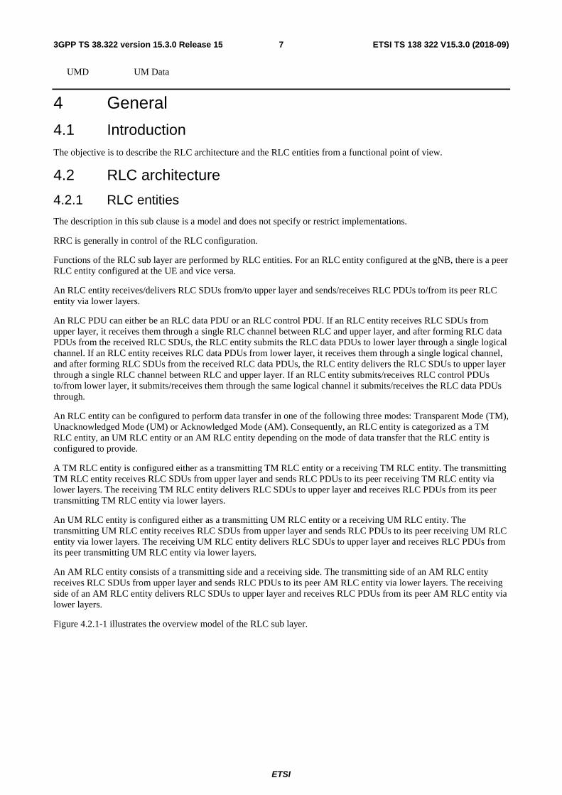
Functions of the RLC sub layer are performed by RLC entities. For an RLC entity configured at the gNB, there is a peer RLC entity configured at the UE and vice versa.
An RLC entity receives/delivers RLC SDUs from/to upper layer and sends/receives RLC PDUs to/from its peer RLC entity via lower layers.
An RLC PDU can either be an RLC data PDU or an RLC control PDU. If an RLC entity receives RLC SDUs from upper layer, it receives them through a single RLC channel between RLC and upper layer, and after forming RLC data PDUs from the received RLC SDUs, the RLC entity submits the RLC data PDUs to lower layer through a single logical channel. If an RLC entity receives RLC data PDUs from lower layer, it receives them through a single logical channel, and after forming RLC SDUs from the received RLC data PDUs, the RLC entity delivers the RLC SDUs to upper layer through a single RLC channel between RLC and upper layer. If an RLC entity submits/receives RLC control PDUs to/from lower layer, it submits/receives them through the same logical channel it submits/receives the RLC data PDUs through.
An RLC entity can be configured to perform data transfer in one of the following three modes: Transparent Mode (TM), Unacknowledged Mode (UM) or Acknowledged Mode (AM). Consequently, an RLC entity is categorized as a TM RLC entity, an UM RLC entity or an AM RLC entity depending on the mode of data transfer that the RLC entity is configured to provide.
A TM RLC entity is configured either as a transmitting TM RLC entity or a receiving TM RLC entity. The transmitting TM RLC entity receives RLC SDUs from upper layer and sends RLC PDUs to its peer receiving TM RLC entity via lower layers. The receiving TM RLC entity delivers RLC SDUs to upper layer and receives RLC PDUs from its peer transmitting TM RLC entity via lower layers.
An UM RLC entity is configured either as a transmitting UM RLC entity or a receiving UM RLC entity. The transmitting UM RLC entity receives RLC SDUs from upper layer and sends RLC PDUs to its peer receiving UM RLC entity via lower layers. The receiving UM RLC entity delivers RLC SDUs to upper layer and receives RLC PDUs from its peer transmitting UM RLC entity via lower layers.
An AM RLC entity consists of a transmitting side and a receiving side. The transmitting side of an AM RLC entity receives RLC SDUs from upper layer and sends RLC PDUs to its peer AM RLC entity via lower layers. The receiving side of an AM RLC entity delivers RLC SDUs to upper layer and receives RLC PDUs from its peer AM RLC entity via lower layers.
Figure 4.2.1-1 illustrates the overview model of the RLC sub layer.

ETSI
ETSI TS 138 322 V15.3.0 (2018-09)83GPP TS 38.322 version 15.3.0 Release 15
radio interface
lower layers
transmitting
TM RLC entity
transmitting
UM RLC entityAM RLC entity
receiving
TM RLC entity
receiving
UM RLC entity
receiving
TM RLC entity
receiving
UM RLC entityAM RLC entity
transmitting
TM RLC entity
transmitting
UM RLC entity
lower layers
upper layer
upper layer
gNB
UE
RLC channel
logical
channel
logical
channel
RLC channel
Figure 4.2.1-1: Overview model of the RLC sub layer
RLC SDUs of variable sizes which are byte aligned (i.e. multiple of 8 bits) are supported for all RLC entity types (i.e. TM, UM and AM RLC entity).
Each RLC SDU is used to construct an RLC PDU without waiting for notification from the lower layer (i.e., by MAC) of a transmission opportunity. In the case of UM and AM RLC entities, an RLC SDU may be segmented and transported using two or more RLC PDUs based on the notification(s) from the lower layer.
RLC PDUs are submitted to lower layer only when a transmission opportunity has been notified by lower layer (i.e. by MAC).
NOTE: The UE should aim to prevent excessive non-consecutive RLC PDUs in a MAC PDU when the UE is requested to generate more than one MAC PDU.
Description of different RLC entity types are provided below.
4.2.1.1 TM RLC entity
4.2.1.1.1 General
A TM RLC entity can be configured to submit/receive RLC PDUs through the following logical channels:
- BCCH, DL/UL CCCH, and PCCH

ETSI
ETSI TS 138 322 V15.3.0 (2018-09)93GPP TS 38.322 version 15.3.0 Release 15
Figure 4.2.1.1.1-1: Model of two transparent mode peer entities
A TM RLC entity submits/receives the following RLC data PDU:
- TMD PDU.
4.2.1.1.2 Transmitting TM RLC entity
When a transmitting TM RLC entity forms TMD PDUs from RLC SDUs, it shall:
- not segment the RLC SDUs;
- not include any RLC headers in the TMD PDUs.
4.2.1.1.3 Receiving TM RLC entity
When a receiving TM RLC entity receives TMD PDUs, it shall:
- deliver the TMD PDUs (which are just RLC SDUs) to upper layer.
4.2.1.2 UM RLC entity
4.2.1.2.1 General
An UM RLC entity can be configured to submit/receive RLC PDUs through the following logical channels:
- DL/UL DTCH
ETSI
ETSI TS 138 322 V15.3.0 (2018-09)103GPP TS 38.322 version 15.3.0 Release 15
Generate RLC header and store in
transmision buffer
SegmentationModify RLC header
Add RLC header
Transmitting UM-RLC entity
UM-RLC channel
radio interface (Uu)
Receiving UM-RLC
entity
UM-RLC channel
UE/GNB GNB/UE
Receptionbuffer
SDU reassembly
Remove RLC header
DTCH DTCH
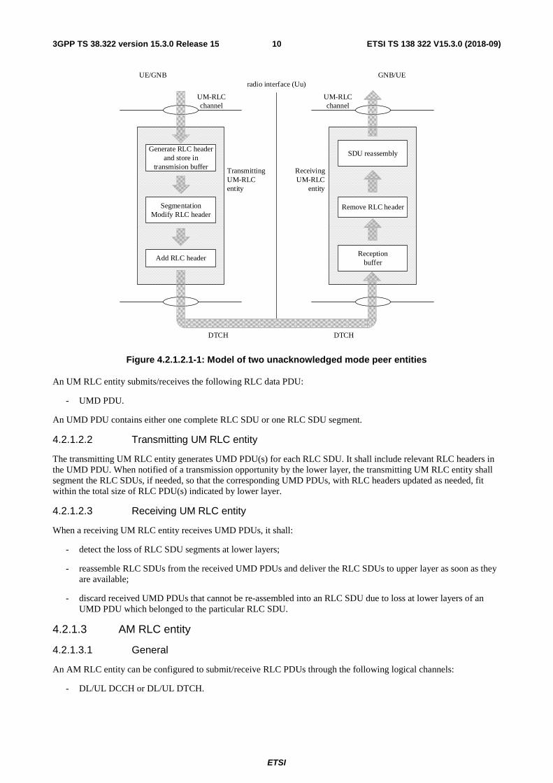
Figure 4.2.1.2.1-1: Model of two unacknowledged mode peer entities
An UM RLC entity submits/receives the following RLC data PDU:
- UMD PDU.
An UMD PDU contains either one complete RLC SDU or one RLC SDU segment.
4.2.1.2.2 Transmitting UM RLC entity
The transmitting UM RLC entity generates UMD PDU(s) for each RLC SDU. It shall include relevant RLC headers in the UMD PDU. When notified of a transmission opportunity by the lower layer, the transmitting UM RLC entity shall segment the RLC SDUs, if needed, so that the corresponding UMD PDUs, with RLC headers updated as needed, fit within the total size of RLC PDU(s) indicated by lower layer.
4.2.1.2.3 Receiving UM RLC entity
When a receiving UM RLC entity receives UMD PDUs, it shall:
- detect the loss of RLC SDU segments at lower layers;
- reassemble RLC SDUs from the received UMD PDUs and deliver the RLC SDUs to upper layer as soon as they are available;
- discard received UMD PDUs that cannot be re-assembled into an RLC SDU due to loss at lower layers of an UMD PDU which belonged to the particular RLC SDU.
4.2.1.3 AM RLC entity
4.2.1.3.1 General
An AM RLC entity can be configured to submit/receive RLC PDUs through the following logical channels:
- DL/UL DCCH or DL/UL DTCH.
ETSI
ETSI TS 138 322 V15.3.0 (2018-09)113GPP TS 38.322 version 15.3.0 Release 15
Generate RLC header and store in transmission
buffer
SegmentationModify RLC header
Add RLC header
Retransmission buffer
RLC control
Routing
Receptionbuffer
SDU reassembly
AM-RLC channel
Remove RLC header
DTCH/DCCH DTCH/DCCH
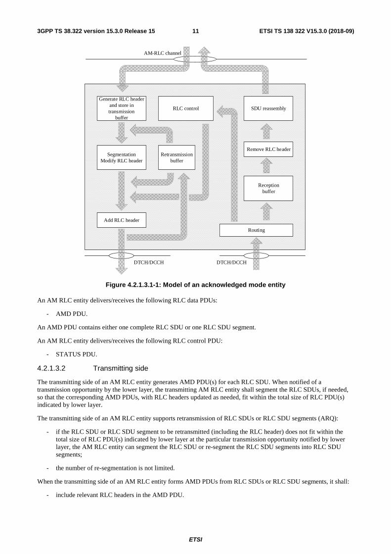
Figure 4.2.1.3.1-1: Model of an acknowledged mode entity
An AM RLC entity delivers/receives the following RLC data PDUs:
- AMD PDU.
An AMD PDU contains either one complete RLC SDU or one RLC SDU segment.
An AM RLC entity delivers/receives the following RLC control PDU:
- STATUS PDU.
4.2.1.3.2 Transmitting side
The transmitting side of an AM RLC entity generates AMD PDU(s) for each RLC SDU. When notified of a transmission opportunity by the lower layer, the transmitting AM RLC entity shall segment the RLC SDUs, if needed, so that the corresponding AMD PDUs, with RLC headers updated as needed, fit within the total size of RLC PDU(s) indicated by lower layer.
The transmitting side of an AM RLC entity supports retransmission of RLC SDUs or RLC SDU segments (ARQ):
- if the RLC SDU or RLC SDU segment to be retransmitted (including the RLC header) does not fit within the total size of RLC PDU(s) indicated by lower layer at the particular transmission opportunity notified by lower layer, the AM RLC entity can segment the RLC SDU or re-segment the RLC SDU segments into RLC SDU segments;
- the number of re-segmentation is not limited.
When the transmitting side of an AM RLC entity forms AMD PDUs from RLC SDUs or RLC SDU segments, it shall:
- include relevant RLC headers in the AMD PDU.

ETSI
ETSI TS 138 322 V15.3.0 (2018-09)123GPP TS 38.322 version 15.3.0 Release 15
4.2.1.3.3 Receiving side
When the receiving side of an AM RLC entity receives AMD PDUs, it shall:
- detect whether or not the AMD PDUs have been received in duplication, and discard duplicated AMD PDUs;
- detect the loss of AMD PDUs at lower layers and request retransmissions to its peer AM RLC entity;
- reassemble RLC SDUs from the received AMD PDUs and deliver the RLC SDUs to upper layer as soon as they are available.
4.3 Services
4.3.1 Services provided to upper layers
The following services are provided by RLC to upper layer:
- TM data transfer;
- UM data transfer;
- AM data transfer, including indication of successful delivery of upper layers PDUs.
4.3.2 Services expected from lower layers
The following services are expected by RLC from lower layer (i.e. MAC):
- data transfer;
- notification of a transmission opportunity, together with the total size of the RLC PDU(s) to be transmitted in the transmission opportunity.
4.4 Functions The following functions are supported by the RLC sub layer:
- transfer of upper layer PDUs;
- error correction through ARQ (only for AM data transfer);
- segmentation and reassembly of RLC SDUs (only for UM and AM data transfer);
- re-segmentation of RLC SDU segments (only for AM data transfer);
- duplicate detection (only for AM data transfer);
- RLC SDU discard (only for UM and AM data transfer);
- RLC re-establishment;
- Protocol error detection (only for AM data transfer).
5 Procedures
5.1 RLC entity handling
5.1.1 RLC entity establishment
When upper layers request an RLC entity establishment, the UE shall:
- establish a RLC entity;
- set the state variables of the RLC entity to initial values;
ETSI
ETSI TS 138 322 V15.3.0 (2018-09)133GPP TS 38.322 version 15.3.0 Release 15
- follow the procedures in subclause 5.2.
5.1.2 RLC entity re-establishment
When upper layers request an RLC entity re-establishment, the UE shall:
- discard all RLC SDUs, RLC SDU segments, and RLC PDUs, if any;
- stop and reset all timers;
- reset all state variables to their initial values.
5.1.3 RLC entity release
When upper layers request an RLC entity release, the UE shall:
- discard all RLC SDUs, RLC SDU segments, and RLC PDUs, if any;
- release the RLC entity.
5.2 Data transfer procedures
5.2.1 TM data transfer
5.2.1.1 Transmit operations
5.2.1.1.1 General
When submitting a new TMD PDU to lower layer, the transmitting TM RLC entity shall:
- submit an RLC SDU without any modification to lower layer.
5.2.1.2 Receive operations
5.2.1.2.1 General
When receiving a new TMD PDU from lower layer, the receiving TM RLC entity shall:
- deliver the TMD PDU without any modification to upper layer.
5.2.2 UM data transfer
5.2.2.1 Transmit operations
5.2.2.1.1 General
When submitting a UMD PDU to lower layer, the transmitting UM RLC entity shall:
- if the UMD PDU contains a segment of an RLC SDU, set the SN of the UMD PDU to TX_Next;
- if the UMD PDU contains a segment that maps to the last byte of an RLC SDU, then increment TX_Next by one.
5.2.2.2 Receive operations
5.2.2.2.1 General
The receiving UM RLC entity shall maintain a reassembly window according to state variable RX_Next_Highest as follows:
- a SN falls within the reassembly window if (RX_Next_Highest – UM_Window_Size) <= SN <RX_Next_Highest;
- a SN falls outside of the reassembly window otherwise.
ETSI
ETSI TS 138 322 V15.3.0 (2018-09)143GPP TS 38.322 version 15.3.0 Release 15
When receiving an UMD PDU from lower layer, the receiving UM RLC entity shall:
- either deliver the UMD PDU to upper layer after removing the RLC header, discard the received UMD PDU, or place it in the reception buffer (see sub clause 5.2.2.2.2);
- if the received UMD PDU was placed in the reception buffer:
- update state variables, reassemble and deliver RLC SDUs to upper layer and start/stop t-Reassembly as needed (see sub clause 5.2.2.2.3).
When t-Reassembly expires, the receiving UM RLC entity shall:
- update state variables, discard RLC SDU segments and start t-Reassembly as needed (see sub clause 5.2.2.2.4).
5.2.2.2.2 Actions when an UMD PDU is received from lower layer
When an UMD PDU is received from lower layer, the receiving UM RLC entity shall:
- if the UMD PDU header does not contain an SN:
- remove the RLC header and deliver the RLC SDU to upper layer.
- else if (RX_Next_Highest – UM_Window_Size) <= SN < RX_Next_Reassembly:
- discard the received UMD PDU.
- else:
- place the received UMD PDU in the reception buffer.
5.2.2.2.3 Actions when an UMD PDU is placed in the reception buffer
When an UMD PDU with SN = x is placed in the reception buffer, the receiving UM RLC entity shall:
- if all byte segments with SN = x are received:
- reassemble the RLC SDU from all byte segments with SN = x, remove RLC headers and deliver the reassembled RLC SDU to upper layer;
- if x = RX_Next_Reassembly:
- update RX_Next_Reassembly to the SN of the first SN > current RX_Next_Reassembly that has not been reassembled and delivered to upper layer.
- else if x falls outside of the reassembly window:
- update RX_Next_Highest to x + 1;
- discard any UMD PDUs with SN that falls outside of the reassembly window;
- if RX_Next_Reassembly falls outside of the reassembly window:
- set RX_Next_Reassembly to the SN of the first SN >= (RX_Next_Highest – UM_Window_Size) that has not been reassembled and delivered to upper layer.
- if t-Reassembly is running:
- if RX_Timer_Trigger <= RX_Next_Reassembly; or
- if RX_Timer_Trigger falls outside of the reassembly window and RX_Timer_Trigger is not equal to RX_Next_Highest; or
- if RX_Next_Highest = RX_Next_Reassembly + 1 and there is no missing byte segment of the RLC SDU associated with SN = RX_Next_Reassembly before the last byte of all received segments of this RLC SDU:
- stop and reset t-Reassembly.
- if t-Reassembly is not running (includes the case when t-Reassembly is stopped due to actions above):

ETSI
ETSI TS 138 322 V15.3.0 (2018-09)153GPP TS 38.322 version 15.3.0 Release 15
- if RX_Next_Highest > RX_Next_Reassembly + 1; or
- if RX_Next_Highest = RX_Next_Reassembly + 1 and there is at least one missing byte segment of the RLC SDU associated with SN = RX_Next_Reassembly before the last byte of all received segments of this RLC SDU:
- start t-Reassembly;
- set RX_Timer_Trigger to RX_Next_Highest.
5.2.2.2.4 Actions when t-Reassembly expires
When t-Reassembly expires, the receiving UM RLC entity shall:
- update RX_Next_Reassembly to the SN of the first SN >= RX_Timer_Trigger that has not been reassembled;
- discard all segments with SN < updated RX_Next_Reassembly;
- if RX_Next_Highest > RX_Next_Reassembly + 1; or
- if RX_Next_Highest = RX_Next_Reassembly + 1 and there is at least one missing byte segment of the RLC SDU associated with SN = RX_Next_Reassembly before the last byte of all received segments of this RLC SDU:
- start t-Reassembly;
- set RX_Timer_Trigger to RX_Next_Highest.
5.2.3 AM data transfer
5.2.3.1 Transmit operations
5.2.3.1.1 General
The transmitting side of an AM RLC entity shall prioritize transmission of RLC control PDUs over AMD PDUs. The transmitting side of an AM RLC entity shall prioritize transmission of AMD PDUs containing previously transmitted RLC SDUs or RLC SDU segments over transmission of AMD PDUs containing not previously transmitted RLC SDUs or RLC SDU segments.
The transmitting side of an AM RLC entity shall maintain a transmitting window according to the state variable TX_Next_Ack as follows:
- a SN falls within the transmitting window if TX_Next_Ack <= SN < TX_Next_Ack + AM_Window_Size;
- a SN falls outside of the transmitting window otherwise.
The transmitting side of an AM RLC entity shall not submit to lower layer any AMD PDU whose SN falls outside of the transmitting window.
For each RLC SDU received from the upper layer, the AM RLC entity shall:
- associate a SN with the RLC SDU equal to TX_Next and construct an AMD PDU by setting the SN of the AMD PDU to TX_Next;
- increment TX_Next by one.
When submitting an AMD PDU that contains a segment of an RLC SDU, to lower layer, the transmitting side of an AM RLC entity shall:
- set the SN of the AMD PDU to the SN of the corresponding RLC SDU.
The transmitting side of an AM RLC entity can receive a positive acknowledgement (confirmation of successful reception by its peer AM RLC entity) for an RLC SDU by the following:
- STATUS PDU from its peer AM RLC entity.
ETSI
ETSI TS 138 322 V15.3.0 (2018-09)163GPP TS 38.322 version 15.3.0 Release 15
When receiving a positive acknowledgement for an RLC SDU with SN = x, the transmitting side of an AM RLC entity shall:
- send an indication to the upper layers of successful delivery of the RLC SDU;
- set TX_Next_Ack equal to the SN of the RLC SDU with the smallest SN, whose SN falls within the range TX_Next_Ack <= SN <= TX_Next and for which a positive acknowledgments has not been received yet.
5.2.3.2 Receive operations
5.2.3.2.1 General
The receiving side of an AM RLC entity shall maintain a receiving window according to the state variable RX_Next as follows:
- a SN falls within the receiving window if RX_Next <= SN < RX_Next + AM_Window_Size;
- a SN falls outside of the receiving window otherwise.
When receiving an AMD PDU from lower layer, the receiving side of an AM RLC entity shall:
- either discard the received AMD PDU or place it in the reception buffer (see sub clause 5.2.3.2.2);
- if the received AMD PDU was placed in the reception buffer:
- update state variables, reassemble and deliver RLC SDUs to upper layer and start/stop t-Reassembly as needed (see sub clause 5.2.3.2.3).
When t-Reassembly expires, the receiving side of an AM RLC entity shall:
- update state variables and start t-Reassembly as needed (see sub clause 5.2.3.2.4).
5.2.3.2.2 Actions when an AMD PDU is received from lower layer
When an AMD PDU is received from lower layer, where the AMD PDU contains byte segment numbers y to z of an RLC SDU with SN = x, the receiving side of an AM RLC entity shall:
- if x falls outside of the receiving window; or
- if byte segment numbers y to z of the RLC SDU with SN = x have been received before:
- discard the received AMD PDU.
- else:
- place the received AMD PDU in the reception buffer;
- if some byte segments of the RLC SDU contained in the AMD PDU have been received before:
- discard the duplicate byte segments.
5.2.3.2.3 Actions when an AMD PDU is placed in the reception buffer
When an AMD PDU with SN = x is placed in the reception buffer, the receiving side of an AM RLC entity shall:
- if x >= RX_Next_Highest
- update RX_Next_Highest to x+ 1.
- if all bytes of the RLC SDU with SN = x are received:
- reassemble the RLC SDU from AMD PDU(s) with SN = x, remove RLC headers when doing so and deliver the reassembled RLC SDU to upper layer;
- if x = RX_Highest_Status,
- update RX_Highest_Status to the SN of the first RLC SDU with SN > current RX_Highest_Status for which not all bytes have been received.
ETSI
ETSI TS 138 322 V15.3.0 (2018-09)173GPP TS 38.322 version 15.3.0 Release 15
- if x = RX_Next:
- update RX_Next to the SN of the first RLC SDU with SN > current RX_Next for which not all bytes have been received.
- if t-Reassembly is running:
- if RX_Next_Status_Trigger = RX_Next; or
- if RX_Next_Status_Trigger = RX_Next + 1 and there is no missing byte segment of the SDU associated with SN = RX_Next before the last byte of all received segments of this SDU; or
- if RX_Next_Status_Trigger falls outside of the receiving window and RX_Next_Status_Trigger is not equal to RX_Next + AM_Window_Size:
- stop and reset t-Reassembly.
- if t-Reassembly is not running (includes the case t-Reassembly is stopped due to actions above):
- if RX_Next_Highest> RX_Next +1; or
- if RX_Next_Highest = RX_Next + 1 and there is at least one missing byte segment of the SDU associated with SN = RX_Next before the last byte of all received segments of this SDU:
- start t-Reassembly;
- set RX_Next_Status_Trigger to RX_Next_Highest.
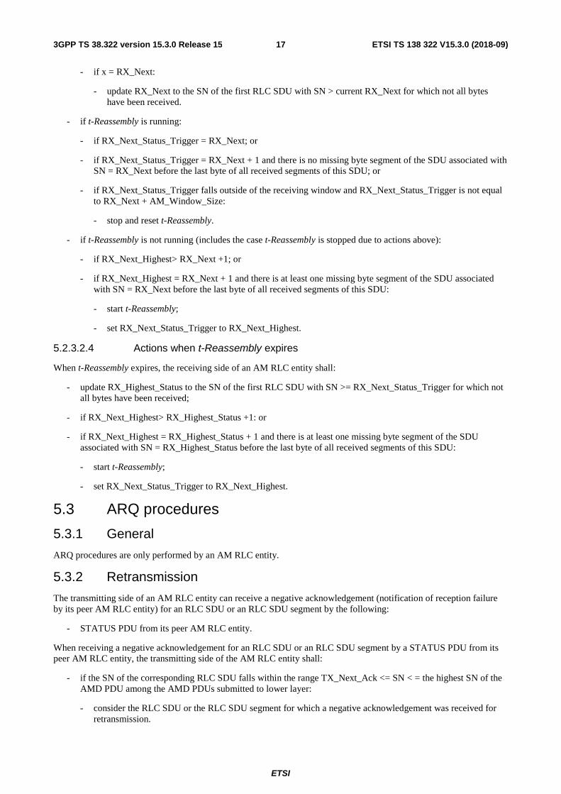
5.2.3.2.4 Actions when t-Reassembly expires
When t-Reassembly expires, the receiving side of an AM RLC entity shall:
- update RX_Highest_Status to the SN of the first RLC SDU with SN >= RX_Next_Status_Trigger for which not all bytes have been received;
- if RX_Next_Highest> RX_Highest_Status +1: or
- if RX_Next_Highest = RX_Highest_Status + 1 and there is at least one missing byte segment of the SDU associated with SN = RX_Highest_Status before the last byte of all received segments of this SDU:
- start t-Reassembly;
- set RX_Next_Status_Trigger to RX_Next_Highest.
5.3 ARQ procedures
5.3.1 General
ARQ procedures are only performed by an AM RLC entity.
5.3.2 Retransmission
The transmitting side of an AM RLC entity can receive a negative acknowledgement (notification of reception failure by its peer AM RLC entity) for an RLC SDU or an RLC SDU segment by the following:
- STATUS PDU from its peer AM RLC entity.
When receiving a negative acknowledgement for an RLC SDU or an RLC SDU segment by a STATUS PDU from its peer AM RLC entity, the transmitting side of the AM RLC entity shall:
- if the SN of the corresponding RLC SDU falls within the range TX_Next_Ack <= SN < = the highest SN of the AMD PDU among the AMD PDUs submitted to lower layer:
- consider the RLC SDU or the RLC SDU segment for which a negative acknowledgement was received for retransmission.
ETSI
ETSI TS 138 322 V15.3.0 (2018-09)183GPP TS 38.322 version 15.3.0 Release 15
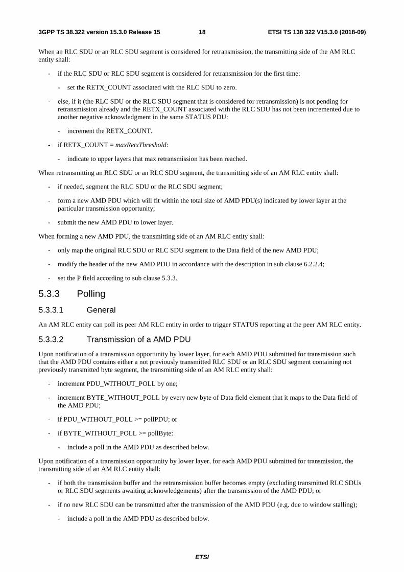
When an RLC SDU or an RLC SDU segment is considered for retransmission, the transmitting side of the AM RLC entity shall:
- if the RLC SDU or RLC SDU segment is considered for retransmission for the first time:
- set the RETX_COUNT associated with the RLC SDU to zero.
- else, if it (the RLC SDU or the RLC SDU segment that is considered for retransmission) is not pending for retransmission already and the RETX_COUNT associated with the RLC SDU has not been incremented due to another negative acknowledgment in the same STATUS PDU:
- increment the RETX_COUNT.
- if RETX_COUNT = maxRetxThreshold:
- indicate to upper layers that max retransmission has been reached.
When retransmitting an RLC SDU or an RLC SDU segment, the transmitting side of an AM RLC entity shall:
- if needed, segment the RLC SDU or the RLC SDU segment;
- form a new AMD PDU which will fit within the total size of AMD PDU(s) indicated by lower layer at the particular transmission opportunity;
- submit the new AMD PDU to lower layer.
When forming a new AMD PDU, the transmitting side of an AM RLC entity shall:
- only map the original RLC SDU or RLC SDU segment to the Data field of the new AMD PDU;
- modify the header of the new AMD PDU in accordance with the description in sub clause 6.2.2.4;
- set the P field according to sub clause 5.3.3.
5.3.3 Polling
5.3.3.1 General
An AM RLC entity can poll its peer AM RLC entity in order to trigger STATUS reporting at the peer AM RLC entity.
5.3.3.2 Transmission of a AMD PDU
Upon notification of a transmission opportunity by lower layer, for each AMD PDU submitted for transmission such that the AMD PDU contains either a not previously transmitted RLC SDU or an RLC SDU segment containing not previously transmitted byte segment, the transmitting side of an AM RLC entity shall:
- increment PDU_WITHOUT_POLL by one;
- increment BYTE_WITHOUT_POLL by every new byte of Data field element that it maps to the Data field of the AMD PDU;
- if PDU_WITHOUT_POLL >= pollPDU; or
- if BYTE_WITHOUT_POLL >= pollByte:
- include a poll in the AMD PDU as described below.
Upon notification of a transmission opportunity by lower layer, for each AMD PDU submitted for transmission, the transmitting side of an AM RLC entity shall:
- if both the transmission buffer and the retransmission buffer becomes empty (excluding transmitted RLC SDUs or RLC SDU segments awaiting acknowledgements) after the transmission of the AMD PDU; or
- if no new RLC SDU can be transmitted after the transmission of the AMD PDU (e.g. due to window stalling);
- include a poll in the AMD PDU as described below.

ETSI
ETSI TS 138 322 V15.3.0 (2018-09)193GPP TS 38.322 version 15.3.0 Release 15
NOTE: Empty RLC buffer (excluding transmitted RLC SDUs or RLC SDU segments awaiting acknowledgements) should not lead to unnecessary polling when data awaits in the upper layer. Details are left up to UE implementation.
To include a poll in an AMD PDU, the transmitting side of an AM RLC entity shall:
- set the P field of the AMD PDU to "1";
- set PDU_WITHOUT_POLL to 0;
- set BYTE_WITHOUT_POLL to 0.
After submitting an AMD PDU including a poll to lower layer, the transmitting side of an AM RLC entity shall:
- set POLL_SN to the highest SN of the AMD PDU among the AMD PDUs submitted to lower layer;
- if t-PollRetransmit is not running:
- start t-PollRetransmit.
- else:
- restart t-PollRetransmit.
5.3.3.3 Reception of a STATUS report
Upon reception of a STATUS report from the receiving RLC AM entity the transmitting side of an AM RLC entity shall:
- if the STATUS report comprises a positive or negative acknowledgement for the RLC SDU with sequence number equal to POLL_SN:
- if t-PollRetransmit is running:
- stop and reset t-PollRetransmit.
5.3.3.4 Expiry of t-PollRetransmit
Upon expiry of t-PollRetransmit, the transmitting side of an AM RLC entity shall:
- if both the transmission buffer and the retransmission buffer are empty (excluding transmitted RLC SDU or RLC SDU segment awaiting acknowledgements); or
- if no new RLC SDU or RLC SDU segment can be transmitted (e.g. due to window stalling):
- consider the RLC SDU with the highest SN among the RLC SDUs submitted to lower layer for retransmission; or
- consider any RLC SDU which has not been positively acknowledged for retransmission.
- include a poll in an AMD PDU as described in section 5.3.3.2.
5.3.4 Status reporting
An AM RLC entity sends STATUS PDUs to its peer AM RLC entity in order to provide positive and/or negative acknowledgements of RLC SDUs (or portions of them).
Triggers to initiate STATUS reporting include:
- Polling from its peer AM RLC entity:
- When an AMD PDU with SN = x and the P field set to "1" is received from lower layer, the receiving side of an AM RLC entity shall:
- if the AMD PDU is to be discarded as specified in subclause 5.2.3.2.2; or
- if x < RX_Highest_Status or x >= RX_Next + AM_Window_Size:

ETSI
ETSI TS 138 322 V15.3.0 (2018-09)203GPP TS 38.322 version 15.3.0 Release 15
- trigger a STATUS report.
- else:
- delay triggering the STATUS report until x < RX_Highest_Status or x >= RX_Next + AM_Window_Size.
NOTE 1: This ensures that the RLC Status report is transmitted after HARQ reordering.
- Detection of reception failure of an AMD PDU
- The receiving side of an AM RLC entity shall trigger a STATUS report when t-Reassembly expires.
NOTE 2: The expiry of t-Reassembly triggers both RX_Highest_Status to be updated and a STATUS report to be triggered, but the STATUS report shall be triggered after RX_Highest_Status is updated.
When STATUS reporting has been triggered, the receiving side of an AM RLC entity shall:
- if t-StatusProhibit is not running:
- at the first transmission opportunity indicated by lower layer, construct a STATUS PDU and submit it to lower layer.
- else:
- at the first transmission opportunity indicated by lower layer after t-StatusProhibit expires, construct a single STATUS PDU even if status reporting was triggered several times while t-StatusProhibit was running and submit it to lower layer.
When a STATUS PDU has been submitted to lower layer, the receiving side of an AM RLC entity shall:
- start t-StatusProhibit.
When constructing a STATUS PDU, the AM RLC entity shall:
- for the RLC SDUs with SN such that RX_Next <= SN < RX_Highest_Status that has not been completely received yet, in increasing SN order of RLC SDUs and increasing byte segment order within RLC SDUs, starting with SN = RX_Next up to the point where the resulting STATUS PDU still fits to the total size of RLC PDU(s) indicated by lower layer:
- for an RLC SDU for which no byte segments have been received yet:
- include in the STATUS PDU a NACK_SN which is set to the SN of the RLC SDU.
- for a continuous sequence of byte segments of a partly received RLC SDU that have not been received yet:
- include in the STATUS PDU a set of NACK_SN, SOstart and SOend.
- for a continuous sequence of RLC SDUs that have not been received yet:
- include in the STATUS PDU a set of NACK_SN and NACK range;
- include in the STATUS PDU, if required, a pair of SOstart and SOend.
- set the ACK_SN to the SN of the next not received RLC SDU which is not indicated as missing in the resulting STATUS PDU.
5.4 SDU discard procedures When indicated from upper layer (i.e. PDCP) to discard a particular RLC SDU, the transmitting side of an AM RLC entity or the transmitting UM RLC entity shall discard the indicated RLC SDU, if neither the RLC SDU nor a segment thereof has been submitted to the lower layers. The transmitting side of an AM RLC entity shall not introduce an RLC SN gap when discarding an RLC SDU.
ETSI
ETSI TS 138 322 V15.3.0 (2018-09)213GPP TS 38.322 version 15.3.0 Release 15
5.5 Data volume calculation For the purpose of MAC buffer status reporting, the UE shall consider the following as RLC data volume:
- RLC SDUs and RLC SDU segments that have not yet been included in an RLC data PDU;
- RLC data PDUs that are pending for initial transmission;
- RLC data PDUs that are pending for retransmission (RLC AM).
In addition, if a STATUS PDU has been triggered and t-StatusProhibit is not running or has expired, the UE shall estimate the size of the STATUS PDU that will be transmitted in the next transmission opportunity, and consider this as part of RLC data volume.
5.6 Handling of unknown, unforeseen and erroneous protocol data
5.6.1 Reception of PDU with reserved or invalid values
When an RLC entity receives an RLC PDU that contains reserved or invalid values, the RLC entity shall:
- discard the received RLC PDU.
6 Protocol data units, formats and parameters
6.1 Protocol data units
6.1.1 General
RLC PDUs can be categorized into RLC data PDUs and RLC control PDUs. RLC data PDUs in sub clause 6.1.2 are used by TM, UM and AM RLC entities to transfer upper layer PDUs (i.e. RLC SDUs). RLC control PDUs in sub clause 6.1.3 are used by AM RLC entity to perform ARQ procedures.
6.1.2 RLC data PDU
a) TMD PDU
TMD PDU is used to transfer upper layer PDUs by a TM RLC entity.
b) UMD PDU
UMD PDU is used to transfer upper layer PDUs by an UM RLC entity.
c) AMD PDU
AMD PDU is used to transfer upper layer PDUs by an AM RLC entity.
6.1.3 RLC control PDU
a) STATUS PDU
STATUS PDU is used by the receiving side of an AM RLC entity to inform the peer AM RLC entity about RLC data PDUs that are received successfully, and RLC data PDUs that are detected to be lost by the receiving side of an AM RLC entity.
6.2 Formats and parameters
6.2.1 General
The formats of RLC PDUs are described in sub clause 6.2.2 and their parameters are described in sub clause 6.2.3.
ETSI
ETSI TS 138 322 V15.3.0 (2018-09)223GPP TS 38.322 version 15.3.0 Release 15
6.2.2 Formats
6.2.2.1 General
RLC PDU is a bit string. In the figures in sub clause 6.2.2.2 to 6.2.2.5, bit strings are represented by tables in which the first and most significant bit is the left most bit of the first line of the table, the last and least significant bit is the rightmost bit of the last line of the table, and more generally the bit string is to be read from left to right and then in the reading order of the lines.
RLC SDUs are bit strings that are byte aligned (i.e. multiple of 8 bits) in length. An RLC SDU is included into an RLC PDU from first bit onward.
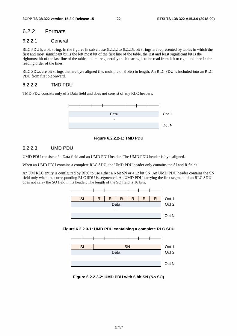
6.2.2.2 TMD PDU
TMD PDU consists only of a Data field and does not consist of any RLC headers.
Figure 6.2.2.2-1: TMD PDU
6.2.2.3 UMD PDU
UMD PDU consists of a Data field and an UMD PDU header. The UMD PDU header is byte aligned.
When an UMD PDU contains a complete RLC SDU, the UMD PDU header only contains the SI and R fields.
An UM RLC entity is configured by RRC to use either a 6 bit SN or a 12 bit SN. An UMD PDU header contains the SN field only when the corresponding RLC SDU is segmented. An UMD PDU carrying the first segment of an RLC SDU does not carry the SO field in its header. The length of the SO field is 16 bits.
SIData
...
Oct N
Oct 1Oct 2
R R RRRR
Figure 6.2.2.3-1: UMD PDU containing a complete RLC SDU
SIData
...
Oct N
Oct 1Oct 2
SN
Figure 6.2.2.3-2: UMD PDU with 6 bit SN (No SO)

ETSI
ETSI TS 138 322 V15.3.0 (2018-09)233GPP TS 38.322 version 15.3.0 Release 15
RSI SN
SN
R
Data...
Oct 3
Oct N
Oct 1
Oct 2
Figure 6.2.2.3-3: UMD PDU with 12 bit SN (No SO)
SO
SO
SN
Oct 3
Oct 4
SI
Data...
Oct N
Oct 1
Oct 2
Figure 6.2.2.3-4: UMD PDU with 6 bit SN and with SO
SO
SO
SN
Oct 3
Oct 4
SI
SN
Data...
Oct 5
Oct N
Oct 1
Oct 2
RR
Figure 6.2.2.3-5: UMD PDU with 12 bit SN and with SO
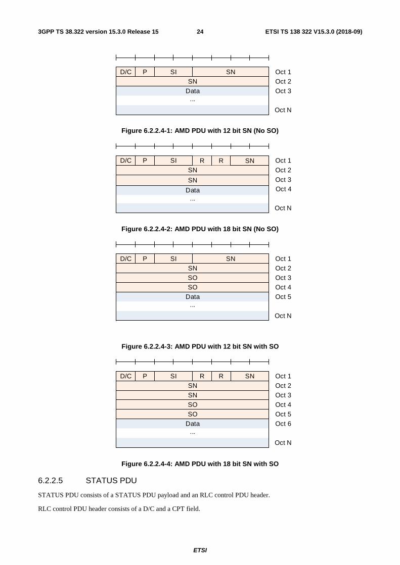
6.2.2.4 AMD PDU
AMD PDU consists of a Data field and an AMD PDU header. The AMD PDU header is byte aligned.
An AM RLC entity is configured by RRC to use either a 12 bit SN or a 18 bit SN. The length of the AMD PDU header is two and three bytes respectively.
An AMD PDU header contains a D/C, a P, a SI, and a SN. An AMD PDU header contains the SO field only when the Data field consists of an RLC SDU segment which is not the first segment, in which case a 16 bit SO is present.
ETSI
ETSI TS 138 322 V15.3.0 (2018-09)243GPP TS 38.322 version 15.3.0 Release 15
D/C P SI SN
SN
Data...
Oct 3
Oct N
Oct 1
Oct 2
Figure 6.2.2.4-1: AMD PDU with 12 bit SN (No SO)
D/C P SI SNSN
Data...
Oct 3
Oct N
Oct 1
Oct 2
SN
R R
Oct 4
Figure 6.2.2.4-2: AMD PDU with 18 bit SN (No SO)
SO
SO
SN
Oct 3
Oct 4
D/C P SI
SN
Data...
Oct 5
Oct N
Oct 1
Oct 2
Figure 6.2.2.4-3: AMD PDU with 12 bit SN with SO
R
SN
SO
SO
Oct 3
Oct 4
D/C P SI SN
SN
Data...
Oct 5
Oct N
Oct 1
Oct 2
Oct 6
R
Figure 6.2.2.4-4: AMD PDU with 18 bit SN with SO
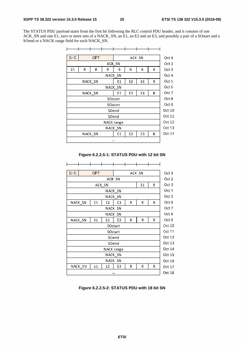
6.2.2.5 STATUS PDU
STATUS PDU consists of a STATUS PDU payload and an RLC control PDU header.
RLC control PDU header consists of a D/C and a CPT field.
ETSI
ETSI TS 138 322 V15.3.0 (2018-09)253GPP TS 38.322 version 15.3.0 Release 15
The STATUS PDU payload starts from the first bit following the RLC control PDU header, and it consists of one ACK_SN and one E1, zero or more sets of a NACK_SN, an E1, an E2 and an E3, and possibly a pair of a SOstart and a SOend or a NACK range field for each NACK_SN.
D/C CPT ACK_SN
ACK_SN
E1
NACK_SN
NACK_SN E1 E2 E3
NACK_SN
NACK_SN E1 E2 E3 R
SOstart
SOstart
SOend
SOend
NACK range
NACK_SN
NACK_SN E1 E2 E3 R
Oct 1
Oct 2
Oct 3
Oct 4
Oct 5
Oct 6
Oct 7
Oct 8
Oct 9
Oct 10
Oct 11
Oct 12
Oct 13
Oct 14
...
R R R R R R R
R
Figure 6.2.2.5-1: STATUS PDU with 12 bit SN
D/C CPT ACK_SN
ACK_SN
Oct 1
Oct 2
Oct 3
Oct 4
Oct 5
Oct 6
Oct 7
Oct 8
Oct 9
Oct 10
Oct 11
Oct 12
Oct 13
Oct 14
Oct 15
ACK_SN E1 R
NACK_SN
NACK_SN
NACK_SN E1 E2 E3 R R R
NACK_SN
NACK_SN
NACK_SN E1 E2 E3
SOstart
SOstart
SOend
SOend
NACK range
NACK_SN
NACK_SN R R R
...
Oct 16
Oct 17
RRR
NACK_SN
Oct 18
E1 E2 E3
Figure 6.2.2.5-2: STATUS PDU with 18 bit SN
ETSI
ETSI TS 138 322 V15.3.0 (2018-09)263GPP TS 38.322 version 15.3.0 Release 15
6.2.3 Parameters
6.2.3.1 General
In the definition of each field in sub clauses 6.2.3.2 to 6.2.3.5, the bits in the parameters are represented in which the first and most significant bit is the left most bit and the last and least significant bit is the rightmost bit. Unless mentioned otherwise, integers are encoded in standard binary encoding for unsigned integers.
6.2.3.2 Data field
Data field elements are mapped to the Data field in the order which they arrive to the RLC entity at the transmitter.
For TMD PDU, UMD PDU and AMD PDU:
- The granularity of the Data field size is one byte;
- The maximum Data field size is the maximum size of a PDCP PDU.
For TMD PDU:
- Only one RLC SDU can be mapped to the Data field of one TMD PDU.
For UMD PDU, and AMD PDU:
- Either of the following can be mapped to the Data field of one UMD PDU, or AMD PDU:
- One RLC SDU;
- One RLC SDU segment.
6.2.3.3 Sequence Number (SN) field
Length: 12 bits or 18 bits (configurable) for AMD PDU. 6 bits or 12 bits (configurable) for UMD PDU.
The SN field indicates the sequence number of the corresponding RLC SDU. For RLC AM, the sequence number is incremented by one for every RLC SDU. For RLC UM, the sequence number is incremented by one for every segmented RLC SDU.
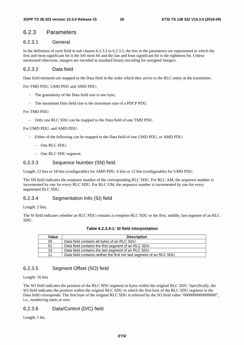
6.2.3.4 Segmentation Info (SI) field
Length: 2 bits.
The SI field indicates whether an RLC PDU contains a complete RLC SDU or the first, middle, last segment of an RLC SDU.
Table 6.2.3.4-1: SI field interpretation
Value Description 00 Data field contains all bytes of an RLC SDU 01 Data field contains the first segment of an RLC SDU 10 Data field contains the last segment of an RLC SDU 11 Data field contains neither the first nor last segment of an RLC SDU
6.2.3.5 Segment Offset (SO) field
Length: 16 bits
The SO field indicates the position of the RLC SDU segment in bytes within the original RLC SDU. Specifically, the SO field indicates the position within the original RLC SDU to which the first byte of the RLC SDU segment in the Data field corresponds. The first byte of the original RLC SDU is referred by the SO field value "0000000000000000", i.e., numbering starts at zero.
6.2.3.6 Data/Control (D/C) field
Length: 1 bit.
ETSI
ETSI TS 138 322 V15.3.0 (2018-09)273GPP TS 38.322 version 15.3.0 Release 15
The D/C field indicates whether the RLC PDU is an RLC data PDU or RLC control PDU. The interpretation of the D/C field is provided in Table 6.2.3.6-1.
Table 6.2.3.6-1: D/C field interpretation
Value Description 0 Control PDU 1 Data PDU
6.2.3.7 Polling bit (P) field
Length: 1 bit.
The P field indicates whether or not the transmitting side of an AM RLC entity requests a STATUS report from its peer AM RLC entity. The interpretation of the P field is provided in Table 6.2.3.7-1.
Table 6.2.3.7-1: P field interpretation
Value Description 0 Status report not requested 1 Status report is requested
6.2.3.8 Reserved (R) field
Length: 1 bit.
The R field is a reserved field for this release of the protocol. The transmitting entity shall set the R field to "0". The receiving entity shall ignore this field.
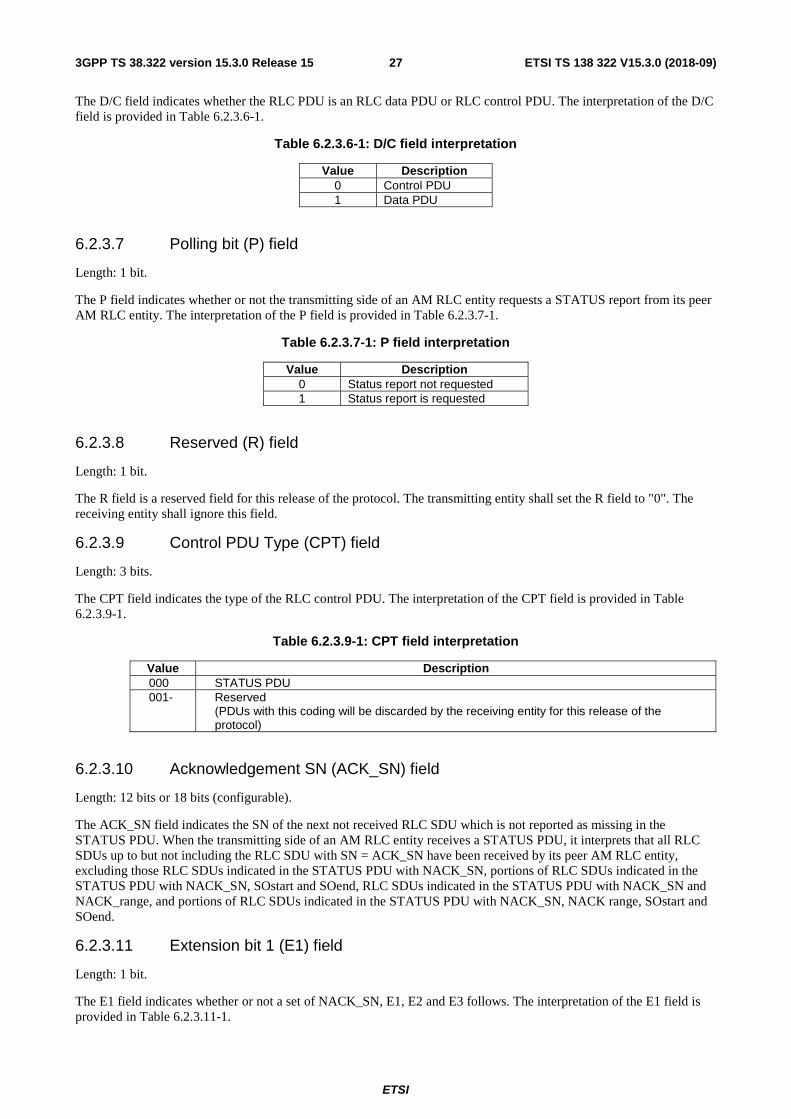
6.2.3.9 Control PDU Type (CPT) field
Length: 3 bits.
The CPT field indicates the type of the RLC control PDU. The interpretation of the CPT field is provided in Table 6.2.3.9-1.
Table 6.2.3.9-1: CPT field interpretation
Value Description 000 STATUS PDU 001- Reserved
(PDUs with this coding will be discarded by the receiving entity for this release of the protocol)
6.2.3.10 Acknowledgement SN (ACK_SN) field
Length: 12 bits or 18 bits (configurable).
The ACK_SN field indicates the SN of the next not received RLC SDU which is not reported as missing in the STATUS PDU. When the transmitting side of an AM RLC entity receives a STATUS PDU, it interprets that all RLC SDUs up to but not including the RLC SDU with SN = ACK_SN have been received by its peer AM RLC entity, excluding those RLC SDUs indicated in the STATUS PDU with NACK_SN, portions of RLC SDUs indicated in the STATUS PDU with NACK_SN, SOstart and SOend, RLC SDUs indicated in the STATUS PDU with NACK_SN and NACK_range, and portions of RLC SDUs indicated in the STATUS PDU with NACK_SN, NACK range, SOstart and SOend.
6.2.3.11 Extension bit 1 (E1) field
Length: 1 bit.
The E1 field indicates whether or not a set of NACK_SN, E1, E2 and E3 follows. The interpretation of the E1 field is provided in Table 6.2.3.11-1.
ETSI
ETSI TS 138 322 V15.3.0 (2018-09)283GPP TS 38.322 version 15.3.0 Release 15
Table 6.2.3.11-1: E1 field interpretation
Value Description 0 A set of NACK_SN, E1, E2 and E3 does not follow. 1 A set of NACK_SN, E1, E2 and E3 follows.
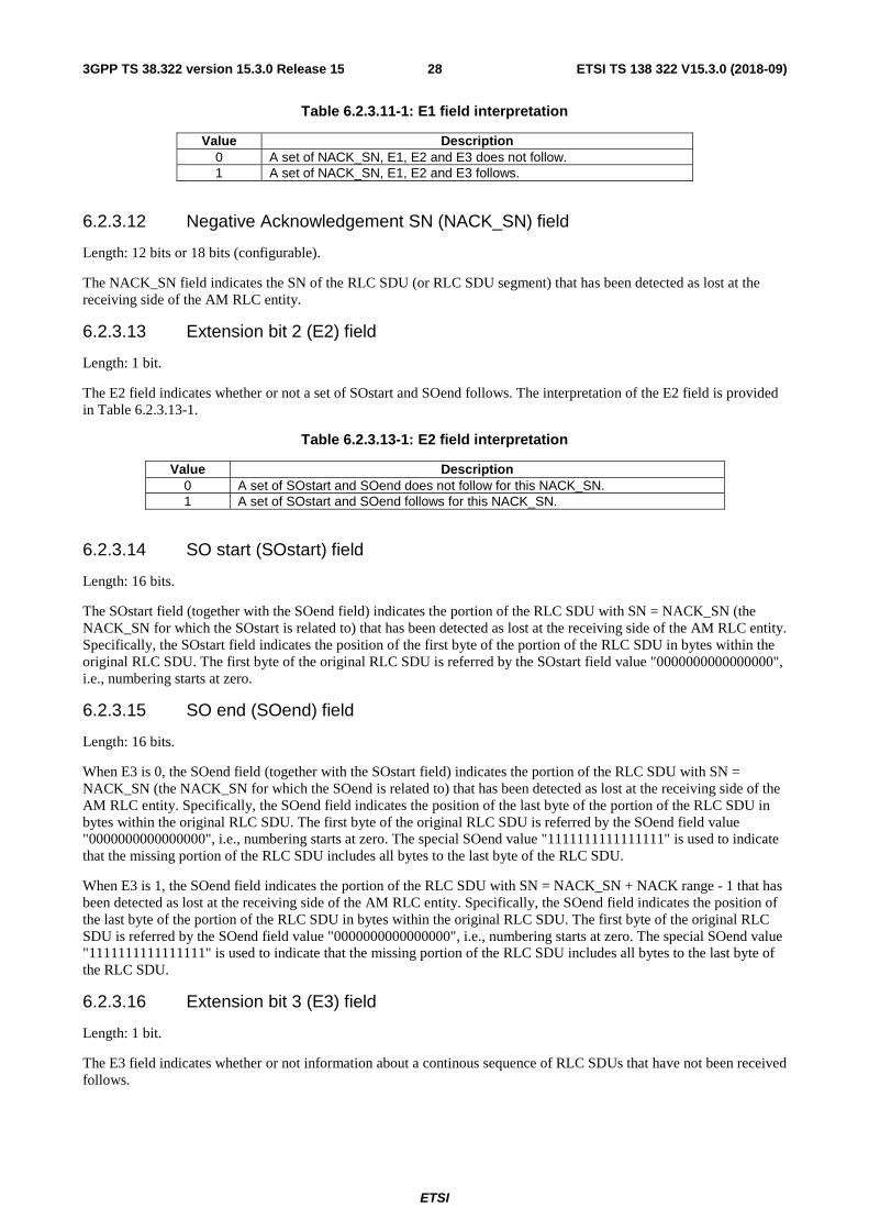
6.2.3.12 Negative Acknowledgement SN (NACK_SN) field
Length: 12 bits or 18 bits (configurable).
The NACK_SN field indicates the SN of the RLC SDU (or RLC SDU segment) that has been detected as lost at the receiving side of the AM RLC entity.
6.2.3.13 Extension bit 2 (E2) field
Length: 1 bit.
The E2 field indicates whether or not a set of SOstart and SOend follows. The interpretation of the E2 field is provided in Table 6.2.3.13-1.
Table 6.2.3.13-1: E2 field interpretation
Value Description 0 A set of SOstart and SOend does not follow for this NACK_SN. 1 A set of SOstart and SOend follows for this NACK_SN.
6.2.3.14 SO start (SOstart) field
Length: 16 bits.
The SOstart field (together with the SOend field) indicates the portion of the RLC SDU with SN = NACK_SN (the NACK_SN for which the SOstart is related to) that has been detected as lost at the receiving side of the AM RLC entity. Specifically, the SOstart field indicates the position of the first byte of the portion of the RLC SDU in bytes within the original RLC SDU. The first byte of the original RLC SDU is referred by the SOstart field value "0000000000000000", i.e., numbering starts at zero.
6.2.3.15 SO end (SOend) field
Length: 16 bits.
When E3 is 0, the SOend field (together with the SOstart field) indicates the portion of the RLC SDU with SN = NACK_SN (the NACK_SN for which the SOend is related to) that has been detected as lost at the receiving side of the AM RLC entity. Specifically, the SOend field indicates the position of the last byte of the portion of the RLC SDU in bytes within the original RLC SDU. The first byte of the original RLC SDU is referred by the SOend field value "0000000000000000", i.e., numbering starts at zero. The special SOend value "1111111111111111" is used to indicate that the missing portion of the RLC SDU includes all bytes to the last byte of the RLC SDU.
When E3 is 1, the SOend field indicates the portion of the RLC SDU with SN = NACK_SN + NACK range - 1 that has been detected as lost at the receiving side of the AM RLC entity. Specifically, the SOend field indicates the position of the last byte of the portion of the RLC SDU in bytes within the original RLC SDU. The first byte of the original RLC SDU is referred by the SOend field value "0000000000000000", i.e., numbering starts at zero. The special SOend value "1111111111111111" is used to indicate that the missing portion of the RLC SDU includes all bytes to the last byte of the RLC SDU.
6.2.3.16 Extension bit 3 (E3) field
Length: 1 bit.
The E3 field indicates whether or not information about a continous sequence of RLC SDUs that have not been received follows.

ETSI
ETSI TS 138 322 V15.3.0 (2018-09)293GPP TS 38.322 version 15.3.0 Release 15
Table 6.2.3.16-1: E3 field interpretation
Value Description 0 NACK range field does not follow for this NACK_SN. 1 NACK range field follows for this NACK_SN.
6.2.3.17 NACK range field
Length: 8 bits
This NACK range field is the number of consecutively lost RLC SDUs starting from and including NACK_SN.
7 Variables, constants and timers
7.1 State variables This sub clause describes the state variables used in AM and UM entities in order to specify the RLC protocol. The state variables defined in this subclause are normative.
All state variables and all counters are non-negative integers.
All state variables related to AM data transfer can take values from 0 to 4095 for 12 bit SN or from 0 to 262143 for 18 bit SN. All arithmetic operations contained in the present document on state variables related to AM data transfer are affected by the AM modulus (i.e. final value = [value from arithmetic operation] modulo 4096 for 12 bit SN and 262144 for 18 bit SN).
All state variables related to UM data transfer can take values from 0 to 63 for 6 bit SN or from 0 to 4095 for 12 bit SN. All arithmetic operations contained in the present document on state variables related to UM data transfer are affected by the UM modulus (i.e. final value = [value from arithmetic operation] modulo 64 for 6 bit SN and 4096 for 12 bit SN).
When performing arithmetic comparisons of state variables or SN values, a modulus base shall be used.
TX_Next_Ack and RX_Next shall be assumed as the modulus base at the transmitting side and receiving side of an AM RLC entity, respectively. This modulus base is subtracted from all the values involved, and then an absolute comparison is performed (e.g. RX_Next <= SN < RX_Next + AM_Window_Size is evaluated as [RX_Next – RX_Next] modulo 2[sn-
FieldLength] <= [SN – RX_Next] modulo 2[sn-FieldLength] < [RX_Next + AM_Window_Size – RX_Next] modulo 2[sn-FieldLength]), where sn-FieldLength is 12 or 18 for 12 bit SN and 18 bit SN, respectively.
RX_Next_Highest– UM_Window_Size shall be assumed as the modulus base at the receiving side of an UM RLC entity. This modulus base is subtracted from all the values involved, and then an absolute comparison is performed (e.g. (RX_Next_Highest– UM_Window_Size) <= SN < RX_Next_Highest is evaluated as [(RX_Next_Highest– UM_Window_Size) – (RX_Next_Highest– UM_Window_Size)] modulo 2[sn-FieldLength] <= [SN – (RX_Next_Highest– UM_Window_Size)] modulo 2[sn-FieldLength] < [RX_Next_Highest– (RX_Next_Highest– UM_Window_Size)] modulo 2[sn-FieldLength]), where sn-FieldLength is 6 or 12 for 6 bit SN and 12 bit SN, respectively.
The transmitting side of each AM RLC entity shall maintain the following state variables:
a) TX_Next_Ack – Acknowledgement state variable
This state variable holds the value of the SN of the next RLC SDU for which a positive acknowledgment is to be received in-sequence, and it serves as the lower edge of the transmitting window. It is initially set to 0, and is updated whenever the AM RLC entity receives a positive acknowledgment for an RLC SDU with SN = TX_Next_Ack.
b) TX_Next – Send state variable
This state variable holds the value of the SN to be assigned for the next newly generated AMD PDU. It is initially set to 0, and is updated whenever the AM RLC entity constructs an AMD PDU with SN = TX_Next and contains an RLC SDU or the last segment of a RLC SDU.
c) POLL_SN – Poll send state variable

ETSI
ETSI TS 138 322 V15.3.0 (2018-09)303GPP TS 38.322 version 15.3.0 Release 15
This state variable holds the value of the highest SN of the AMD PDU among the AMD PDUs submitted to lower layer when POLL_SN is set according to sub clause 5.3.3.2. It is initially set to 0.
The transmitting side of each AM RLC entity shall maintain the following counters:
a) PDU_WITHOUT_POLL – Counter
This counter is initially set to 0. It counts the number of AMD PDUs sent since the most recent poll bit was transmitted.
b) BYTE_WITHOUT_POLL – Counter
This counter is initially set to 0. It counts the number of data bytes sent since the most recent poll bit was transmitted.
c) RETX_COUNT – Counter
This counter counts the number of retransmissions of an RLC SDU or RLC SDU segment (see subclause 5.3.2). There is one RETX_COUNT counter maintained per RLC SDU.
The receiving side of each AM RLC entity shall maintain the following state variables:
a) RX_Next – Receive state variable
This state variable holds the value of the SN following the last in-sequence completely received RLC SDU, and it serves as the lower edge of the receiving window. It is initially set to 0, and is updated whenever the AM RLC entity receives an RLC SDU with SN = RX_Next.
b) RX_Next_Status_Trigger – t-Reassembly state variable
This state variable holds the value of the SN following the SN of the RLC SDU which triggered t-Reassembly.
c) RX_Highest_Status – Maximum STATUS transmit state variable
This state variable holds the highest possible value of the SN which can be indicated by "ACK_SN" when a STATUS PDU needs to be constructed. It is initially set to 0.
d) RX_Next_Highest – Highest received state variable
This state variable holds the value of the SN following the SN of the RLC SDU with the highest SN among received RLC SDUs. It is initially set to 0.
Each transmitting UM RLC entity shall maintain the following state variables:
a) TX_Next
This state variable holds the value of the SN to be assigned for the next newly generated UMD PDU with segment. It is initially set to 0, and is updated after the UM RLC entity submits a UMD PDU including the last segment of an RLC SDU to lower layers.
Each receiving UM RLC entity shall maintain the following state variables and constant:
b) RX_Next_Reassembly – UM receive state variable
This state variable holds the value of the earliest SN that is still considered for reassembly. It is initially set to 0.
c) RX_Timer_Trigger – UM t-Reassembly state variable
This state variable holds the value of the SN following the SN which triggered t-Reassembly.
d) RX_Next_Highest– UM receive state variable
This state variable holds the value of the SN following the SN of the UMD PDU with the highest SN among received UMD PDUs. It serves as the higher edge of the reassembly window. It is initially set to 0.
7.2 Constants a) AM_Window_Size
ETSI
ETSI TS 138 322 V15.3.0 (2018-09)313GPP TS 38.322 version 15.3.0 Release 15
This constant is used by both the transmitting side and the receiving side of each AM RLC entity. AM_Window_Size = 2048 when a 12 bit SN is used, AM_Window_Size = 131072 when an 18 bit SN is used.
b) UM_Window_Size
This constant is used by the receiving UM RLC entity to define SNs of those UMD SDUs that can be received without causing an advancement of the receiving window. UM_Window_Size = 32 when a 6 bit SN is configured, UM_Window_Size = 2048 when a 12 bit SN is configured.
7.3 Timers The following timers are configured by 3GPP TS 38.331 [5]:
a) t-PollRetransmit
This timer is used by the transmitting side of an AM RLC entity in order to retransmit a poll (see sub clause 5.3.3).
b) t-Reassembly
This timer is used by the receiving side of an AM RLC entity and receiving UM RLC entity in order to detect loss of RLC PDUs at lower layer (see sub clauses 5.2.2.2 and 5.2.3.2). If t-Reassembly is running, t-Reassembly shall not be started additionally, i.e. only one t-Reassembly per RLC entity is running at a given time.
c) t-StatusProhibit
This timer is used by the receiving side of an AM RLC entity in order to prohibit transmission of a STATUS PDU (see sub clause 5.3.4).
7.4 Configurable parameters The following parameters are configured by 3GPP TS 38.331 [5]:
a) maxRetxThreshold
This parameter is used by the transmitting side of each AM RLC entity to limit the number of retransmissions corresponding to an RLC SDU, including its segments (see subclause 5.3.2).
b) pollPDU
This parameter is used by the transmitting side of each AM RLC entity to trigger a poll for every pollPDU PDUs (see subclause 5.3.3).
c) pollByte
This parameter is used by the transmitting side of each AM RLC entity to trigger a poll for every pollByte bytes (see subclause 5.3.3).
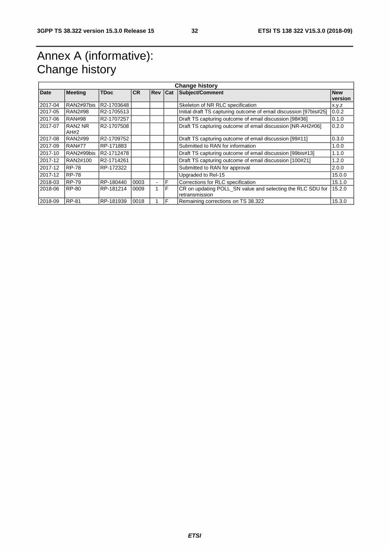
ETSI
ETSI TS 138 322 V15.3.0 (2018-09)323GPP TS 38.322 version 15.3.0 Release 15
Annex A (informative): Change history
Change history Date Meeting TDoc CR Rev Cat Subject/Comment New
version 2017-04 RAN2#97bis R2-1703648 Skeleton of NR RLC specification x.y.z 2017-05 RAN2#98 R2-1705513 Initial draft TS capturing outcome of email discussion [97bis#25] 0.0.2 2017-06 RAN#98 R2-1707257 Draft TS capturing outcome of email discussion [98#36] 0.1.0 2017-07 RAN2 NR
AH#2 R2-1707508 Draft TS capturing outcome of email discussion [NR-AH2#06] 0.2.0
2017-08 RAN2#99 R2-1709752 Draft TS capturing outcome of email discussion [99#11] 0.3.0 2017-09 RAN#77 RP-171883 Submitted to RAN for information 1.0.0 2017-10 RAN2#99bis R2-1712478 Draft TS capturing outcome of email discussion [99bis#13] 1.1.0 2017-12 RAN2#100 R2-1714261 Draft TS capturing outcome of email discussion [100#21] 1.2.0 2017-12 RP-78 RP-172322 Submitted to RAN for approval 2.0.0 2017-12 RP-78 Upgraded to Rel-15 15.0.0 2018-03 RP-79 RP-180440 0003 - F Corrections for RLC specification 15.1.0 2018-06 RP-80 RP-181214 0009 1 F CR on updating POLL_SN value and selecting the RLC SDU for
retransmission 15.2.0
2018-09 RP-81 RP-181939 0018 1 F Remaining corrections on TS 38.322 15.3.0

ETSI
ETSI TS 138 322 V15.3.0 (2018-09)333GPP TS 38.322 version 15.3.0 Release 15
History
Document history
V15.2.0 September 2018 Publication
V15.3.0 September 2018 Publication