TS 129 275 - V13.5.0 - Universal Mobile … · 3GPP TS 29.275 version 13.5.0 Release 13 ETSI 2 ETSI...
109
ETSI TS 1 Universal Mobile Te Proxy based Mobili (3GPP TS 29.2 TECHNICAL SPECIFICATION 129 275 V13.5.0 (201 elecommunications System ( LTE; Mobile IPv6 (PMIPv6) ity and Tunnelling protocols Stage 3 275 version 13.5.0 Release 1 N 16-08) (UMTS); s; 13)
Transcript of TS 129 275 - V13.5.0 - Universal Mobile … · 3GPP TS 29.275 version 13.5.0 Release 13 ETSI 2 ETSI...
ETSI TS 1
Universal Mobile Tel
Proxy based Mobilit
(3GPP TS 29.2
TECHNICAL SPECIFICATION
129 275 V13.5.0 (2016
elecommunications System (LTE;
y Mobile IPv6 (PMIPv6) ility and Tunnelling protocols;
Stage 3 .275 version 13.5.0 Release 13
ION
16-08)
(UMTS);
ls;
13)
ETSI
ETSI TS 129 275 V13.5.0 (2016-08)13GPP TS 29.275 version 13.5.0 Release 13
Reference RTS/TSGC-0429275vd50
Keywords LTE,UMTS
ETSI
650 Route des Lucioles F-06921 Sophia Antipolis Cedex - FRANCE
Tel.: +33 4 92 94 42 00 Fax: +33 4 93 65 47 16
Siret N° 348 623 562 00017 - NAF 742 C
Association à but non lucratif enregistrée à la Sous-Préfecture de Grasse (06) N° 7803/88
Important notice
The present document can be downloaded from: http://www.etsi.org/standards-search
The present document may be made available in electronic versions and/or in print. The content of any electronic and/or print versions of the present document shall not be modified without the prior written authorization of ETSI. In case of any
existing or perceived difference in contents between such versions and/or in print, the only prevailing document is the print of the Portable Document Format (PDF) version kept on a specific network drive within ETSI Secretariat.
Users of the present document should be aware that the document may be subject to revision or change of status. Information on the current status of this and other ETSI documents is available at
https://portal.etsi.org/TB/ETSIDeliverableStatus.aspx
If you find errors in the present document, please send your comment to one of the following services: https://portal.etsi.org/People/CommiteeSupportStaff.aspx
Copyright Notification
No part may be reproduced or utilized in any form or by any means, electronic or mechanical, including photocopying and microfilm except as authorized by written permission of ETSI.
The content of the PDF version shall not be modified without the written authorization of ETSI. The copyright and the foregoing restriction extend to reproduction in all media.
© European Telecommunications Standards Institute 2016.
All rights reserved.
DECTTM, PLUGTESTSTM, UMTSTM and the ETSI logo are Trade Marks of ETSI registered for the benefit of its Members. 3GPPTM and LTE™ are Trade Marks of ETSI registered for the benefit of its Members and
of the 3GPP Organizational Partners. GSM® and the GSM logo are Trade Marks registered and owned by the GSM Association.
ETSI
ETSI TS 129 275 V13.5.0 (2016-08)23GPP TS 29.275 version 13.5.0 Release 13
Intellectual Property Rights IPRs essential or potentially essential to the present document may have been declared to ETSI. The information pertaining to these essential IPRs, if any, is publicly available for ETSI members and non-members, and can be found in ETSI SR 000 314: "Intellectual Property Rights (IPRs); Essential, or potentially Essential, IPRs notified to ETSI in respect of ETSI standards", which is available from the ETSI Secretariat. Latest updates are available on the ETSI Web server (https://ipr.etsi.org/).
Pursuant to the ETSI IPR Policy, no investigation, including IPR searches, has been carried out by ETSI. No guarantee can be given as to the existence of other IPRs not referenced in ETSI SR 000 314 (or the updates on the ETSI Web server) which are, or may be, or may become, essential to the present document.
Foreword This Technical Specification (TS) has been produced by ETSI 3rd Generation Partnership Project (3GPP).
The present document may refer to technical specifications or reports using their 3GPP identities, UMTS identities or GSM identities. These should be interpreted as being references to the corresponding ETSI deliverables.
The cross reference between GSM, UMTS, 3GPP and ETSI identities can be found under http://webapp.etsi.org/key/queryform.asp.
Modal verbs terminology In the present document "shall", "shall not", "should", "should not", "may", "need not", "will", "will not", "can" and "cannot" are to be interpreted as described in clause 3.2 of the ETSI Drafting Rules (Verbal forms for the expression of provisions).
"must" and "must not" are NOT allowed in ETSI deliverables except when used in direct citation.
ETSI
ETSI TS 129 275 V13.5.0 (2016-08)33GPP TS 29.275 version 13.5.0 Release 13
Contents
Intellectual Property Rights ................................................................................................................................ 2
Foreword ............................................................................................................................................................. 2
Modal verbs terminology .................................................................................................................................... 2
Foreword ........................................................................................................................................................... 10
1 Scope ...................................................................................................................................................... 11
2 References .............................................................................................................................................. 11
3 Definitions and abbreviations ................................................................................................................. 13
3.1 Definitions ........................................................................................................................................................ 13
3.2 Abbreviations ................................................................................................................................................... 13
4 General ................................................................................................................................................... 14
4.1 PDN connection ............................................................................................................................................... 14
4.2 PMIPv6 protocol stacks .................................................................................................................................... 14
5 Mobility Management procedures .......................................................................................................... 15
5.1 Proxy Mobile IPv6 PDN Connection Creation procedure ................................................................................ 15
5.1.1 General ........................................................................................................................................................ 15
5.1.1.1 Proxy Binding Update ........................................................................................................................... 15
5.1.1.2 Proxy Binding Acknowledgement ........................................................................................................ 19
5.1.2 MAG procedures ........................................................................................................................................ 22
5.1.3 LMA procedures ......................................................................................................................................... 22
5.2 Proxy Mobile IPv6 PDN Connection Lifetime Extension procedure ............................................................... 23
5.2.1 General ........................................................................................................................................................ 23
5.2.1.1 Proxy Binding Update ........................................................................................................................... 23
5.2.1.2 Proxy Binding Acknowledgement ........................................................................................................ 25
5.2.2 MAG procedures ........................................................................................................................................ 27
5.2.3 LMA procedures ......................................................................................................................................... 27
5.3 Proxy Mobile IPv6 PDN Connection Handover procedure .............................................................................. 28
5.3.1 General ........................................................................................................................................................ 28
5.3.1.1 Proxy Binding Update ........................................................................................................................... 28
5.3.1.2 Proxy Binding Acknowledgement ........................................................................................................ 32
5.3.2 MAG procedures ........................................................................................................................................ 34
5.3.3 LMA procedures ......................................................................................................................................... 35
5.4 Proxy Mobile IPv6 MAG Initiated PDN Connection Deletion procedure ....................................................... 36
5.4.1 General ........................................................................................................................................................ 36
5.4.1.1 Proxy Binding Update ........................................................................................................................... 36
5.4.1.2 Proxy Binding Acknowledgement ........................................................................................................ 38
5.4.2 MAG procedures ........................................................................................................................................ 39
5.4.3 LMA procedures ......................................................................................................................................... 39
5.5 Proxy Mobile IPv6 LMA Initiated PDN Connection Deletion procedure ....................................................... 40
5.5.1 General ........................................................................................................................................................ 40
5.5.1.1 Binding Revocation Indication.............................................................................................................. 40
5.5.2 MAG procedures ........................................................................................................................................ 42
5.5.3 LMA procedures ......................................................................................................................................... 43
5.6 Proxy Mobile IPv6 PDN Connection IPv4 address allocation procedure ........................................................ 43
5.6.1 General ........................................................................................................................................................ 43
5.6.1.1 Proxy Binding Update ........................................................................................................................... 43
5.6.1.2 Proxy Binding Acknowledgement ........................................................................................................ 44
5.6.2 MAG procedures ........................................................................................................................................ 46
5.6.3 LMA procedures ......................................................................................................................................... 46
5.7 Proxy Mobile IPv6 LMA Initiated IPv4 Address Release procedure ............................................................... 46
5.7.1 General ........................................................................................................................................................ 46
5.7.1.1 Binding Revocation Indication.............................................................................................................. 46
5.7.1.2 Binding Revocation Acknowledgment ................................................................................................. 47
5.7.2 MAG procedures ........................................................................................................................................ 48
ETSI
ETSI TS 129 275 V13.5.0 (2016-08)43GPP TS 29.275 version 13.5.0 Release 13
5.7.3 LMA procedures ......................................................................................................................................... 48
5.8 Proxy Mobile IPv6 Multiple PDN Extensions ................................................................................................. 48
5.8.1 General ........................................................................................................................................................ 48
5.8.2 Extensions to PMIPv6 Data Structure ........................................................................................................ 49
5.8.3 Extensions to PMIPv6 BULE and BCE Lookups ....................................................................................... 49
5.8.3.1 General .................................................................................................................................................. 49
5.8.3.2 Extensions to PMIPv6 BCE Lookups ................................................................................................... 49
5.8.3.3 Extensions to PMIPv6 BULE Lookups................................................................................................. 50
5.8.4 Extensions to PMIPv6 Procedure ............................................................................................................... 50
5.8.4.1 General .................................................................................................................................................. 50
5.8.4.2 MAG procedure .................................................................................................................................... 50
5.8.4.3 LMA procedure ..................................................................................................................................... 50
5.9 Serving GW Procedure at Chaining Case ......................................................................................................... 50
5.9.1 General ........................................................................................................................................................ 50
5.9.2 Signalling procedures ................................................................................................................................. 50
5.9.2.1 PMIP-based S8 Serving GW procedures .............................................................................................. 51
5.9.3 Payload packets at chained case ................................................................................................................. 51
5.10 Proxy Mobile IPv6 MAG Initiated IPv4 Address Release procedure .............................................................. 52
5.10.1 General ........................................................................................................................................................ 52
5.10.1.1 Proxy Binding Update ........................................................................................................................... 52
5.10.1.2 Proxy Binding Acknowledgement ........................................................................................................ 53
5.10.2 MAG procedures ........................................................................................................................................ 54
5.10.3 LMA procedures ......................................................................................................................................... 54
5.11 Proxy Mobile IPv6 LMA Initiated Update Notification procedure .................................................................. 54
5.11.1 General ........................................................................................................................................................ 54
5.11.1.1 Update Notification ............................................................................................................................... 54
5.11.1.2 Update Notification Acknowledgement ................................................................................................ 55
5.11.2 LMA procedures ......................................................................................................................................... 56
5.11.3 MAG procedures ........................................................................................................................................ 56
5.12 Proxy Mobile IPv6 Mobile Network Prefix Allocation procedure ................................................................... 56
5.12.1 General ........................................................................................................................................................ 56
5.12.1.1 Proxy Binding Update ........................................................................................................................... 56
5.12.1.2 Proxy Binding Acknowledgement ........................................................................................................ 57
5.12.2 MAG procedures ........................................................................................................................................ 58
5.12.3 LMA procedures ......................................................................................................................................... 59
6 Tunnel Management procedures ............................................................................................................ 60
6.1 General ............................................................................................................................................................. 60
6.2 MAG procedure ................................................................................................................................................ 60
6.3 LMA procedure ................................................................................................................................................ 61
6.4 Data Structures ................................................................................................................................................. 61
6.4.1 Binding Update List Entry .......................................................................................................................... 61
6.4.2 Binding Cache Entry ................................................................................................................................... 62
6.5 Security ............................................................................................................................................................ 63
7 Path Management procedures ................................................................................................................ 64
7.1 General ............................................................................................................................................................. 64
7.2 Heartbeat Mechanism ....................................................................................................................................... 64
7.2.1 General ........................................................................................................................................................ 64
7.2.2 Heartbeat Message ...................................................................................................................................... 64
7.2.2.1 Heartbeat Request ................................................................................................................................. 64
7.2.2.2 Heartbeat Response ............................................................................................................................... 64
7.3 Void .................................................................................................................................................................. 65
7.4 Void .................................................................................................................................................................. 65
7.5 Void .................................................................................................................................................................. 65
7.6 UE-specific Error Handling .............................................................................................................................. 65
7.6.1 General ........................................................................................................................................................ 65
7.6.2 MAG and LMA procedure ......................................................................................................................... 65
7.7 Void .................................................................................................................................................................. 65
7.8 Partial node failure requiring the removal of a subset of sessions .................................................................... 65
7.8.1 General ........................................................................................................................................................ 65
7.8.2 Binding Revocation Indication message ..................................................................................................... 65
ETSI
ETSI TS 129 275 V13.5.0 (2016-08)53GPP TS 29.275 version 13.5.0 Release 13
7.8.3 Binding Revocation Acknowledgement message ....................................................................................... 66
7.8.4 MAG procedures ........................................................................................................................................ 66
7.8.5 LMA procedures ......................................................................................................................................... 67
8 PMIP-based S5 and PMIP-based S8 description.................................................................................... 68
8.1 Initial Attach procedures .................................................................................................................................. 68
8.1.1 General ........................................................................................................................................................ 68
8.1.2 Serving GW procedures .............................................................................................................................. 68
8.1.3 PDN GW procedures .................................................................................................................................. 68
8.2 Serving GW Initiated PDN Connection Lifetime Extension procedures ......................................................... 68
8.2.1 General ........................................................................................................................................................ 68
8.2.2 Serving GW procedures .............................................................................................................................. 68
8.2.3 PDN GW procedures .................................................................................................................................. 68
8.3 UE, MME or HSS initiated Detach procedures ................................................................................................ 68
8.3.1 General ........................................................................................................................................................ 68
8.3.2 Serving GW procedures .............................................................................................................................. 68
8.3.3 PDN GW procedures .................................................................................................................................. 68
8.4 PDN GW Initiated PDN Disconnection procedures ......................................................................................... 69
8.4.1 General ........................................................................................................................................................ 69
8.4.2 Serving GW procedures .............................................................................................................................. 69
8.4.3 PDN GW procedures .................................................................................................................................. 69
8.5 UE Requested Additional PDN Connectivity procedures ................................................................................ 69
8.5.1 General ........................................................................................................................................................ 69
8.5.2 Serving GW procedures .............................................................................................................................. 69
8.5.3 PDN GW procedures .................................................................................................................................. 69
8.6 Handover procedures ........................................................................................................................................ 69
8.6.1 Intra-LTE TAU and Inter-eNodeB Handover with Serving GW Relocation procedures ........................... 69
8.6.1.1 General .................................................................................................................................................. 69
8.6.1.2 Serving GW procedures ........................................................................................................................ 69
8.6.1.3 PDN GW procedures............................................................................................................................. 69
8.6.2 TAU/RAU or Handover between GERAN A/Gb Mode or UTRAN Iu Mode and E-UTRAN procedures ................................................................................................................................................... 70
8.6.2.1 General .................................................................................................................................................. 70
8.6.2.2 Serving GW procedures ........................................................................................................................ 70
8.6.2.3 PDN GW procedures............................................................................................................................. 70
8.6.3 Handover from Trusted or Untrusted Non-3GPP IP Access over S2a/S2b to 3GPP Access Handover E-UTRAN over PMIP based S5/S8 without optimization procedures ....................................................... 70
8.6.3.1 General .................................................................................................................................................. 70
8.6.3.2 Serving GW procedures ........................................................................................................................ 70
8.6.3.3 PDN GW procedures............................................................................................................................. 70
8.6.4 Handover from Trusted or Untrusted Non-3GPP IP Access over S2a/S2b to 3GPP Access UTRAN/GERAN over PMIP based S5/S8 without optimization ............................................................... 70
8.6.4.1 General .................................................................................................................................................. 70
8.6.4.2 Serving GW procedures ........................................................................................................................ 70
8.6.4.3 PDN GW procedures............................................................................................................................. 70
8.6.5 Handover from Trusted or Untrusted Non-3GPP IP Access over S2c to 3GPP Access over PMIP based S5/S8 without optimization .............................................................................................................. 71
8.6.5.1 General .................................................................................................................................................. 71
8.6.5.2 Serving GW procedures ........................................................................................................................ 71
8.6.5.3 PDN GW procedures............................................................................................................................. 71
8.6.6 Void ............................................................................................................................................................ 71
8.6.7 Void ............................................................................................................................................................ 71
8.7 UE Requested PDN Disconnection procedures ................................................................................................ 71
8.7.1 General ........................................................................................................................................................ 71
8.7.2 Serving GW procedures .............................................................................................................................. 71
8.7.3 PDN GW procedures .................................................................................................................................. 71
8.8 IPv4 Address Allocation using DHCP ............................................................................................................. 71
8.8.1 General ........................................................................................................................................................ 71
8.8.2 Serving GW procedures .............................................................................................................................. 71
8.8.3 PDN GW procedures .................................................................................................................................. 71
8.9 PDN-GW Initiated IPv4 Address Delete Procedure ......................................................................................... 72
8.9.1 General ........................................................................................................................................................ 72
ETSI
ETSI TS 129 275 V13.5.0 (2016-08)63GPP TS 29.275 version 13.5.0 Release 13
8.9.2 Serving GW procedures .............................................................................................................................. 72
8.9.3 PDN GW procedures .................................................................................................................................. 72
8.10 Mobile Network Prefix Allocation using DHCPv6 Prefix Delegation ............................................................. 72
8.10.1 General ........................................................................................................................................................ 72
8.10.2 Serving GW procedures .............................................................................................................................. 72
8.10.3 PDN GW procedures .................................................................................................................................. 72
9 Trusted Non-3GPP Access over S2a Description .................................................................................. 72
9.0 General ............................................................................................................................................................. 72
9.1 Initial Attach procedures .................................................................................................................................. 72
9.1.1 General ........................................................................................................................................................ 72
9.1.2 Trusted Non-3GPP Access procedures ....................................................................................................... 72
9.1.3 PDN GW procedures .................................................................................................................................. 72
9.2 Trusted Non-3GPP Access Initiated PDN Connection Lifetime Extension procedures ................................... 73
9.2.1 General ........................................................................................................................................................ 73
9.2.2 Trusted Non-3GPP Access procedures ....................................................................................................... 73
9.2.3 PDN GW procedures .................................................................................................................................. 73
9.3 UE / Trusted Non-3GPP Access Initiated Detach and UE Requested PDN Disconnection procedures .......... 73
9.3.1 General ........................................................................................................................................................ 73
9.3.2 Trusted Non-3GPP Access procedures ....................................................................................................... 73
9.3.3 PDN GW procedures .................................................................................................................................. 73
9.4 HSS / AAA Initiated Detach procedures .......................................................................................................... 73
9.4.1 General ........................................................................................................................................................ 73
9.4.2 Trusted Non-3GPP Access procedures ....................................................................................................... 73
9.4.3 PDN GW procedures .................................................................................................................................. 73
9.5 UE Initiated Connectivity to Additional PDN procedures ............................................................................... 74
9.5.1 General ........................................................................................................................................................ 74
9.5.2 Trusted Non-3GPP Access procedures ....................................................................................................... 74
9.5.3 PDN GW procedures .................................................................................................................................. 74
9.6 3GPP Access to Trusted Non-3GPP IP Access with PMIPv6 on S2a Handover procedures without optimization ...................................................................................................................................................... 74
9.6.1 General ........................................................................................................................................................ 74
9.6.2 Trusted Non-3GPP Access procedures ....................................................................................................... 74
9.6.3 PDN GW procedures .................................................................................................................................. 74
9.7 PDN GW Initiated Resource Allocation Deactivation procedures ................................................................... 74
9.7.1 General ........................................................................................................................................................ 74
9.7.2 Trusted Non-3GPP Access procedures ....................................................................................................... 74
9.7.3 PDN GW procedures .................................................................................................................................. 74
9.8 IPv4 Address Allocation using DHCP ............................................................................................................. 75
9.8.1 General ........................................................................................................................................................ 75
9.8.2 Trusted Non-3GPP Access procedures ....................................................................................................... 75
9.8.3 PDN GW procedures .................................................................................................................................. 75
9.9 PDN-GW Initiated IPv4 Address Delete Procedure ......................................................................................... 75
9.9.1 General ........................................................................................................................................................ 75
9.9.2 Trusted Non-3GPP Access procedures ....................................................................................................... 75
9.9.3 PDN GW procedures .................................................................................................................................. 75
9.10 Optimized E-UTRAN to CDMA2000 eHRPD Handover procedure ............................................................... 75
9.10.1 General ........................................................................................................................................................ 75
9.10.2 CDMA2000 HRPD access procedure ......................................................................................................... 75
9.10.3 PDN GW procedures .................................................................................................................................. 75
9.11 Optimized Idle Mode Mobility: E-UTRAN Access to cdma2000 eHRPD Access procedure ......................... 76
9.11.1 General ........................................................................................................................................................ 76
9.11.2 CDMA2000 eHRPD access procedure ....................................................................................................... 76
9.11.3 PDN GW procedures .................................................................................................................................. 76
10 Untrusted Non-3GPP Access over S2b Description .............................................................................. 76
10.1 Initial Attach procedures .................................................................................................................................. 76
10.1.1 General ........................................................................................................................................................ 76
10.1.2 ePDG procedures ........................................................................................................................................ 76
10.1.3 PDN GW procedures .................................................................................................................................. 77
10.2 ePDG Initiated PDN Connection Lifetime Extension procedures .................................................................... 77
10.2.1 General ........................................................................................................................................................ 77
ETSI
ETSI TS 129 275 V13.5.0 (2016-08)73GPP TS 29.275 version 13.5.0 Release 13
10.2.2 ePDG procedures ........................................................................................................................................ 77
10.2.3 PDN GW procedures .................................................................................................................................. 77
10.3 UE / ePDG Initiated Detach and UE Requested PDN Disconnection procedures ........................................... 77
10.3.1 General ........................................................................................................................................................ 77
10.3.2 ePDG procedures ........................................................................................................................................ 77
10.3.3 PDN GW procedures .................................................................................................................................. 78
10.4 HSS / AAA Initiated Detach procedures .......................................................................................................... 78
10.4.1 General ........................................................................................................................................................ 78
10.4.2 ePDG procedures ........................................................................................................................................ 78
10.4.3 PDN GW procedures .................................................................................................................................. 78
10.5 UE Initiated Connectivity to Additional PDN procedures ............................................................................... 78
10.5.1 General ........................................................................................................................................................ 78
10.5.2 ePDG procedures ........................................................................................................................................ 78
10.5.3 PDN GW procedures .................................................................................................................................. 79
10.6 3GPP Access to Untrusted Non-3GPP IP Access with PMIPv6 on S2b Handover procedures without optimization ...................................................................................................................................................... 79
10.6.1 General ........................................................................................................................................................ 79
10.6.2 ePDG procedures ........................................................................................................................................ 79
10.6.3 PDN GW procedures .................................................................................................................................. 79
10.7 PDN GW Initiated Resource Allocation Deactivation procedures ................................................................... 79
10.7.1 General ........................................................................................................................................................ 79
10.7.2 ePDG procedures ........................................................................................................................................ 79
10.7.3 PDN GW procedures .................................................................................................................................. 79
10.8 PDN-GW Initiated IPv4 Address Delete Procedure ......................................................................................... 80
10.8.1 General ........................................................................................................................................................ 80
10.8.2 ePDG procedures ........................................................................................................................................ 80
10.8.3 PDN GW procedures .................................................................................................................................. 80
11 S2a and S2b Chaining with PMIP-based S8 Description ....................................................................... 80
11.1 Initial Attach procedures .................................................................................................................................. 80
11.1.1 General ........................................................................................................................................................ 80
11.1.2 ePDG / Trusted Non-3GPP Access procedures .......................................................................................... 80
11.1.3 Serving GW procedures .............................................................................................................................. 80
11.2 ePDG / Trusted Non-3GPP Access Initiated PDN Connection Lifetime Extension procedures ...................... 81
11.2.1 General ........................................................................................................................................................ 81
11.2.2 ePDG / Trusted Non-3GPP Access procedures .......................................................................................... 81
11.2.3 Serving GW procedures .............................................................................................................................. 81
11.3 UE / ePDG / Trusted Non-3GPP Access Initiated Detach procedures ............................................................. 81
11.3.1 General ........................................................................................................................................................ 81
11.3.2 ePDG / Trusted Non-3GPP Access procedures .......................................................................................... 81
11.3.3 Serving GW procedures .............................................................................................................................. 81
11.4 HSS / AAA Initiated Detach procedures .......................................................................................................... 81
11.4.1 General ........................................................................................................................................................ 81
11.4.2 ePDG / Trusted Non-3GPP Access procedures .......................................................................................... 81
11.4.3 Serving GW procedures .............................................................................................................................. 81
11.5 UE Initiated Connectivity to Additional PDN procedures ............................................................................... 82
11.5.1 General ........................................................................................................................................................ 82
11.5.2 ePDG / Trusted Non-3GPP Access procedures .......................................................................................... 82
11.5.3 Serving GW procedures .............................................................................................................................. 82
11.6 3GPP Access to Trusted / Untrusted Non-3GPP IP Access Handover procedures without optimization ........ 82
11.6.1 General ........................................................................................................................................................ 82
11.6.2 ePDG / Trusted Non-3GPP Access procedures .......................................................................................... 82
11.6.3 Serving GW procedures .............................................................................................................................. 82
11.7 UE Requested PDN Disconnection procedures ................................................................................................ 83
11.7.1 General ........................................................................................................................................................ 83
11.7.2 ePDG / Trusted Non-3GPP Access procedures .......................................................................................... 83
11.7.3 Serving GW procedures .............................................................................................................................. 83
11.8 PDN GW Initiated Resource Allocation Deactivation procedures ................................................................... 83
11.8.1 General ........................................................................................................................................................ 83
11.8.2 ePDG / Trusted Non-3GPP Access procedures .......................................................................................... 83
11.8.3 Serving GW procedures .............................................................................................................................. 83
ETSI
ETSI TS 129 275 V13.5.0 (2016-08)83GPP TS 29.275 version 13.5.0 Release 13
12 Information Elements ............................................................................................................................. 83
12.1 Additional Proxy Mobile IPv6 Information Elements ...................................................................................... 83
12.1.1 3GPP-Specific PMIPv6 Information Elements ........................................................................................... 83
12.1.1.0 General .................................................................................................................................................. 83
12.1.1.1 3GPP Specific PMIPv6 error code ........................................................................................................ 85
12.1.1.2 Fully Qualified PDN Connection Set Identifier (FQ-CSID) ................................................................. 85
12.1.1.3 PDN Type Indication ............................................................................................................................ 86
12.1.1.4 PDN GW IP address.............................................................................................................................. 86
12.1.1.5 DHCPv4 Address Allocation Procedure Indication .............................................................................. 87
12.1.1.6 Charging ID........................................................................................................................................... 87
12.1.1.7 Selection Mode ..................................................................................................................................... 87
12.1.1.8 Charging Characteristics ....................................................................................................................... 88
12.1.1.9 Serving Network ................................................................................................................................... 88
12.1.1.10 Mobile Equipment Identity ................................................................................................................... 88
12.1.1.11 MSISDN ............................................................................................................................................... 88
12.1.1.12 APN Restriction .................................................................................................................................... 89
12.1.1.13 Maximum APN Restriction ................................................................................................................... 89
12.1.1.14 Unauthenticated IMSI ........................................................................................................................... 89
12.1.1.15 PDN Connection ID .............................................................................................................................. 89
12.1.1.16 PGW Back-Off Time ............................................................................................................................ 90
12.1.1.17 Signalling Priority Indication ................................................................................................................ 90
12.1.1.18 Static IP Address Allocation Indication ................................................................................................ 90
12.1.1.19 Additional Protocol Configuration Options .......................................................................................... 91
12.1.1.20 MME/SGSN Identifier .......................................................................................................................... 91
12.1.1.21 End Marker Notification ....................................................................................................................... 91
12.1.1.22 Trusted WLAN Mode Indication .......................................................................................................... 91
12.1.1.23 UE Time Zone ....................................................................................................................................... 92
12.1.1.24 Access Network Identifier Timestamp .................................................................................................. 92
12.1.1.25 Logical Access ID ................................................................................................................................. 93
12.1.1.26 Origination Time Stamp ........................................................................................................................ 93
12.1.1.27 Maximum Wait Time ............................................................................................................................ 94
12.1.1.28 TWAN Capabilities ............................................................................................................................... 94
13 Trusted WLAN Access over S2a Description ........................................................................................ 94
13.1 Initial Attach procedures .................................................................................................................................. 94
13.1.1 General ........................................................................................................................................................ 94
13.1.2 TWAN procedures ...................................................................................................................................... 94
13.1.3 PDN GW procedures .................................................................................................................................. 95
13.2 TWAN Initiated PDN Connection Lifetime Extension procedures ................................................................. 96
13.2.1 General ........................................................................................................................................................ 96
13.2.2 TWAN procedures ...................................................................................................................................... 96
13.2.3 PDN GW procedures .................................................................................................................................. 96
13.3 UE / TWAN Initiated Detach and UE/TWAN Requested PDN Disconnection procedures ............................ 96
13.3.1 General ........................................................................................................................................................ 96
13.3.2 TWAN procedures ...................................................................................................................................... 96
13.3.3 PDN GW procedures .................................................................................................................................. 96
13.4 HSS / AAA Initiated Detach procedures .......................................................................................................... 96
13.4.1 General ........................................................................................................................................................ 96
13.4.2 TWAN procedures ...................................................................................................................................... 96
13.4.3 PDN GW procedures .................................................................................................................................. 97
13.5 PDN GW Initiated Resource Allocation Deactivation procedures ................................................................... 97
13.5.1 General ........................................................................................................................................................ 97
13.5.2 TWAN procedures ...................................................................................................................................... 97
13.5.3 PDN GW procedures .................................................................................................................................. 97
13.6 3GPP Access to TWAN with PMIPv6 on S2a Handover procedures without optimization ............................ 97
13.6.1 General ........................................................................................................................................................ 97
13.6.2 TWAN procedures ...................................................................................................................................... 97
13.6.3 PDN GW procedures .................................................................................................................................. 98
13.7 UE Initiated Connectivity to Additional PDN procedures ............................................................................... 98
13.7.1 General ........................................................................................................................................................ 98
13.7.2 TWAN procedures ...................................................................................................................................... 98
13.7.3 PDN GW procedures .................................................................................................................................. 98
ETSI
ETSI TS 129 275 V13.5.0 (2016-08)93GPP TS 29.275 version 13.5.0 Release 13
14 Proxy Mobile IPv6 EPC Restoration Procedure .................................................................................... 99
14.1 PGW triggered SGW restoration procedure ..................................................................................................... 99
14.1.1 General ........................................................................................................................................................ 99
14.1.2 Serving GW procedures .............................................................................................................................. 99
14.1.3 PDN GW procedures .................................................................................................................................. 99
14.2 Update PDP context/Bearer at P-CSCF failure ................................................................................................ 99
14.2.1 General ........................................................................................................................................................ 99
14.2.2 PDN GW procedures .................................................................................................................................. 99
14.2.3 Serving GW, TWAN and ePDG procedures ............................................................................................ 100
14.3 Inform UE about P-CSCF failure ................................................................................................................... 100
14.3.1 General ...................................................................................................................................................... 100
14.3.2 PDN GW procedures ................................................................................................................................ 100
14.3.3 Serving GW procedures ............................................................................................................................ 100
15 Proxy Mobile IPv6 End Marker Notification Procedure ...................................................................... 101
15.1 General ........................................................................................................................................................... 101
15.2 Serving GW procedures ................................................................................................................................. 101
15.3 PDN GW procedures ...................................................................................................................................... 101
Annex A: void ....................................................................................................................................... 102
Annex B (Normative): Definition of the protocol number in pseudo-header ................................ 102
B.1 General ........................................................................................................................................................... 102
B.2 Interworking of different protocol number ..................................................................................................... 102
Annex C (informative): Change History ........................................................................................... 102
History ............................................................................................................................................................ 108
ETSI
ETSI TS 129 275 V13.5.0 (2016-08)103GPP TS 29.275 version 13.5.0 Release 13
Foreword This Technical Specification has been produced by the 3rd Generation Partnership Project (3GPP).
The contents of the present document are subject to continuing work within the TSG and may change following formal TSG approval. Should the TSG modify the contents of the present document, it will be re-released by the TSG with an identifying change of release date and an increase in version number as follows:
Version x.y.z
where:
x the first digit:
1 presented to TSG for information;
2 presented to TSG for approval;
3 or greater indicates TSG approved document under change control.
y the second digit is incremented for all changes of substance, i.e. technical enhancements, corrections, updates, etc.
z the third digit is incremented when editorial only changes have been incorporated in the document.nt.
ETSI
ETSI TS 129 275 V13.5.0 (2016-08)113GPP TS 29.275 version 13.5.0 Release 13
1 Scope The present document specifies the stage 3 of the PMIPv6 Based Mobility and Tunnelling Protocols used over the PMIP-based S2a, S2b, S5, and S8 reference points defined in 3GPP TS 23.402 [3], and are thus applicable to the Serving GW, PDN Gateway, ePDG, and Trusted Non-3GPP Access. Protocols specifications are compliant with relevant IETF RFCs. In this specification PMIP refers to PMIPv6 as defined in IETF RFC5213 [4] taking into account the corrections regarding the protocol number definition in IETF RFC6275 [8].
2 References The following documents contain provisions which, through reference in this text, constitute provisions of the present document.
• References are either specific (identified by date of publication, edition number, version number, etc.) or non-specific.
• For a specific reference, subsequent revisions do not apply.
• For a non-specific reference, the latest version applies. In the case of a reference to a 3GPP document (including a GSM document), a non-specific reference implicitly refers to the latest version of that document in the same Release as the present document.
[1] 3GPP TR 21.905: "Vocabulary for 3GPP Specifications".
[2] 3GPP TS 23.401: "GPRS enhancements for E-UTRAN access ".
[3] 3GPP TS 23.402: "Architecture Enhancements for non-3GPP accesses".
[4] IETF RFC 5213: "Proxy Mobile IPv6".
[5] IETF RFC 5844: "IPv4 Support for Proxy Mobile IPv6".
[6] IETF RFC 5846: "Binding Revocation for IPv6 Mobility".
[7] IETF RFC 5845: "Generic Routing Encapsulation (GRE) Key Option for Proxy Mobile IPv6".
[8] IETF RFC 6275: "Mobility Support in IPv6".
[9] IETF RFC 4282: "The Network Access Identifier".
[10] IETF RFC 4283: "Mobile Node Identifier Option for Mobile IPv6 (MIPv6)".
[11] IETF RFC 5149: "Service Selection for Mobile Ipv6".
[12] 3GPP TS 23.003: "Numbering, addressing and identification".
[13] 3GPP TS 23.007: "Restoration Procedures".
[14] Void
[15] Void
[16] 3GPP TS 24.008: "Mobile radio interface Layer 3 specification; Core network protocols".
[17] IETF RFC 5847: "Heartbeat Mechanism for Proxy Mobile IPv6".
[18] IANA Mobile Ipv6 Parameters Registry, <http://www.iana.org/assignments/mobility-parameters >.
[19] 3GPP TS 33.402: "3GPP System Architecture Evolution (SAE); Security aspects of non-3GPP accesses".
[20] IETF RFC 2784: "Generic Routing Encapsulation (GRE)".
ETSI
ETSI TS 129 275 V13.5.0 (2016-08)123GPP TS 29.275 version 13.5.0 Release 13
[21] IETF RFC 2890: "Key and Sequence Number Extensions to GRE".
[22] 3GPP TS 29.274: "3GPP Evolved Packet System (EPS); Evolved General Packet Radio Service (GPRS) Tunnelling Protocol for Control plane (GTPv2-C); Stage 3".
[23] 3GPP TS 23.060: "General Packet Radio Service (GPRS); Service description; Stage 2".
[24] 3GPP TS 29.282: "Mobile IPv6 vendor specific option format and usage within 3GPP".
[25] 3GPP TS 32.251: "Charging Management; Packet Switched (PS) domain charging".
[26] 3GPP TS 32.298: "Charging Management; Charging Data Record (CDR) parameter description".
[27] IETF RFC 4291: "IP Version 6 Addressing Architecture".
[28] 3GPP TS 29.060: "General Packet Radio Service (GPRS); GPRS Tunnelling Protocol (GTP) across the Gn and Gp interface".
[29] ITU-T Recommendation E.164: "The international public telecommunication numbering plan".
[30] 3GPP TS 29.212: "Policy and Charging Control (PCC); Reference points".
[31] IETF RFC 2473: "Generic Packet Tunneling in IPv6 Specification".
[32] IANA Registry of Assigned Numbers. Mobile IPv6 parameters, Status Codes: http://www.iana.org/assignments/mobility-parameters/mobility-parameters.xhtml#mobility-parameters-6.
[33] IANA Registry of Assigned Numbers. Mobile IPv6 parameters, Binding Revocation Acknowledgement Status Codes: http://www.iana.org/assignments/mobility-parameters/mobility-parameters.xhtml#binding-revocation-status-codes.
[34] IETF RFC5555: "Mobile IPv6 Support for Dual Stack Hosts and Routers".
[35] IETF RFC 7077: "Update Notifications for Proxy Mobile IPv6".
[36] 3GPP TS 23.380: "IMS Restoration Procedures".
[37] IETF RFC 6757: "Access Network Identifier Option".
[38] IETF RFC 3775, "Mobility Support in IPv6".
[39] 3GPP TS 24.302: "Access to the 3GPP Evolved Packet Core (EPC) via non-3GPP access networks; Stage 3".
[40] IETF RFC 5905, "Network Time Protocol Version 4: Protocol and Algorithms Specification".
[41] IETF RFC 7563: "Extensions to the Proxy Mobile IPv6 (PMIPv6) Access Network Identifier Option".
[42] IETF RFC 3046: "DHCP Relay Agent Information Option".
[43] IETF RFC 6463: "Runtime Local Mobility Anchor (LMA) Assignment Support for Proxy Mobile IPv6".
[44] IETF RFC 7389: "Separation of Control and User Plane for Proxy Mobile IPv6".
[45] IETF RFC 7148: "Prefix Delegation Support for Proxy Mobile IPv6".
ETSI
ETSI TS 129 275 V13.5.0 (2016-08)133GPP TS 29.275 version 13.5.0 Release 13
3 Definitions and abbreviations
3.1 Definitions For the purposes of the present document, the terms and definitions given in 3GPP TR 21.905 [1] and the following apply. A term defined in the present document takes precedence over the definition of the same term, if any, in 3GPP TR 21.905 [1].
The following terms used in this Technical Specification are defined in:
- the PMIPv6 specification IETF RFC 5213 [4]: IPv6 Home Network Prefix, Proxy Care-of Address, Local Mobility Anchor Address;
- the IPv4 Support for PMIPv6 specification IETF RFC 5844 [5]: IPv4 Home Address, IPv4 Local Mobility Anchor Address;
- the MIPv6 specification [8] and extended by the PMIPv6 specification IETF RFC 5213 [4]: Binding Cache Entry, Binding Update List Entry;
- the Binding Revocation for IPv6 Mobility [6]: Binding Revocation Indication and Binding Revocation Acknowledgement;
- the Separation of Control and User Plane for PMIPv6 specification IETF RFC 7389 [44]: LMA User-Plane Address.
Local Mobility Anchor: Within EPS the Local Mobility Anchor functionality consists of a PMIPv6 Local Mobility Anchor as described in the PMIPv6 specification IETF RFC 5213 [4] with support of IPv4 Support for PMIPv6 as defined in IETF RFC 5844 [5], Binding Revocation for IPv6 Mobility as defined in IETF RFC 5846 [6], GRE Key Option for PMIPv6 as defined in IETF RFC 5845 [7], and PMIPv6 Heartbeat Mechanism as defined in IETF RFC 5847 [17].
Mobile Access Gateway: Within EPS the Mobility Access Gateway functionality consists of a PMIPv6 Mobility Access Gateway as described in the PMIPv6 specification IETF RFC 5213 [4] with support of IPv4 Support for PMIPv6 as defined in IETF RFC 5844 [5], Binding Revocation for IPv6 Mobility as defined in IETF RFC 5846 [6], GRE Key Option for PMIPv6 as defined in IETF RFC 5845 [7], and PMIPv6 Heartbeat Mechanism as defined in IETF RFC 5847 [17].
PDN Connection: The association between a UE represented by one IPv4 Home Address and/or one IPv6 Home Network Prefix, and a PDN represented by an APN. On a PMIPv6 peer (MAG or LMA) there is a one-to-one mapping between a PDN connection and a PMIPv6 binding.
3.2 Abbreviations For the purposes of the present document, the abbreviations given in 3GPP TR 21.905 [1] and the following apply. An abbreviation defined in the present document takes precedence over the definition of the same abbreviation, if any, in 3GPP TR 21.905 [1].
3GSPEC 3GPP Specific PMIPv6 Error Code BCE Binding Cache Entry BRA Binding Revocation Acknowledgement BRI Binding Revocation Indication BULE Binding Update List Entry EPC Evolved Packet Core ePDG Evolved Packet Data Gateway GRE Generic Routing Encapsulation GW Gateway IMSI International Mobile Subscriber Identity IMEI International Mobile station Equipment Identity IPv4-LMAA IPv4 LMAA LMA Local Mobility Anchor LMAA LMA Address
ETSI
ETSI TS 129 275 V13.5.0 (2016-08)143GPP TS 29.275 version 13.5.0 Release 13
MAG Mobility Access Gateway MIPv6 Mobile IPv6 NAI Network Access Identifier PBA Proxy Binding Acknowledgment PBU Proxy Binding Update PMIPv6 Proxy MIPv6 Proxy-CoA Proxy Care-of Address TWAN Trusted WLAN Access Network UPN Update Notification UPA Update Notification Acknowledgment
4 General
4.1 PDN connection On a PMIPv6 peer (MAG or LMA) there is a one-to-one mapping between a PDN connection and a PMIPv6 binding.
Traffic sent over a given PDN connection is encapsulated with GRE [20] using different, per-interface per-PDN connection, per direction (uplink and downlink) GRE keys [21] to allow multiplexing and demultiplexing of traffic belonging to different PDN connections at MAG and LMA. For the handover between 3GPP access and non-3GPP access, the uplink GRE Key shall be the same.
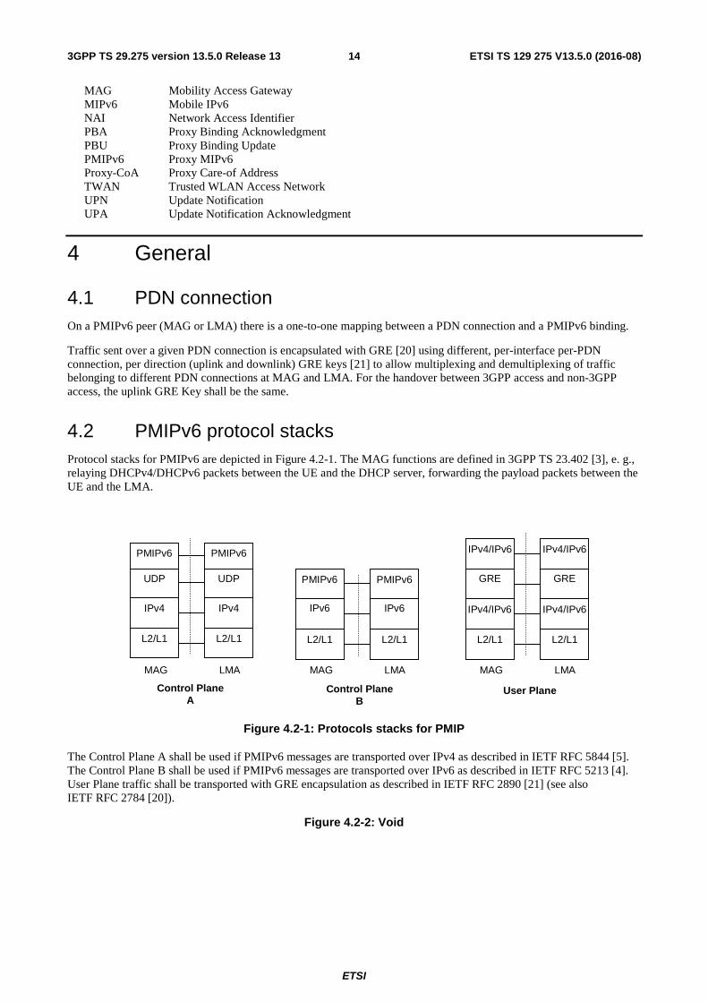
4.2 PMIPv6 protocol stacks Protocol stacks for PMIPv6 are depicted in Figure 4.2-1. The MAG functions are defined in 3GPP TS 23.402 [3], e. g., relaying DHCPv4/DHCPv6 packets between the UE and the DHCP server, forwarding the payload packets between the UE and the LMA.
UDP UDP
IPv4/IPv6
L2/L1
IPv4/IPv6
L2/L1
GRE
IPv4/IPv6
MAG
LMA
Control Plane A
User Plane
GRE
IPv4/IPv6
IPv6
L2/L1
IPv6
L2/L1
MAG
LMA
MAG
LMA
IPv4
L2/L1
IPv4
L2/L1
Control Plane B
PMIPv6 PMIPv6
PMIPv6 PMIPv6
Figure 4.2-1: Protocols stacks for PMIP
The Control Plane A shall be used if PMIPv6 messages are transported over IPv4 as described in IETF RFC 5844 [5]. The Control Plane B shall be used if PMIPv6 messages are transported over IPv6 as described in IETF RFC 5213 [4]. User Plane traffic shall be transported with GRE encapsulation as described in IETF RFC 2890 [21] (see also IETF RFC 2784 [20]).
Figure 4.2-2: Void
ETSI
ETSI TS 129 275 V13.5.0 (2016-08)153GPP TS 29.275 version 13.5.0 Release 13
5 Mobility Management procedures
5.1 Proxy Mobile IPv6 PDN Connection Creation procedure
5.1.1 General
The PMIPv6 PDN Connection Creation procedure is initiated by the node acting as a MAG to create a new PDN connection with the node acting as an LMA for an UE that either attaches for the first time to the EPC, or connects to an additional PDN. The procedure starts with the MAG sending a PBU including the APN to the LMA to register with the LMA a binding for the UE's PDN connection. If multiple PDN connections to the same APN function is supported by the MAG, a PDN connection ID shall also be included in the same PBU message. The LMA confirms establishment of the binding by sending a PBA to the MAG. If multiple PDN connections to the same APN function is supported by the LMA, the received PDN connection ID shall also be included in the same PBA message. Establishment of the binding achieves the following:
- PDN selection: The LMA select the PDN based on the APN contained in the PBU.
- IPv6 Home Network Prefix assignment: The LMA assigns to the UE's PDN connection an IPv6 Home Network Prefix valid in the selected PDN.
- IPv4 Home Address assignment: The LMA assigns to the UE's PDN connection an IPv4 Home Address valid in the selected PDN.
- Downlink and Uplink GRE Key Assignment: The MAG and LMA will establish downlink and uplink GRE keys to be used for GRE encapsulation of the PDN connection's downlink and uplink traffic, respectively.
- GRE Tunnel Establishment: A GRE tunnel is established between the MAG and LMA with the assigned GRE keys to carry uplink and downlink traffic that the UE respectively sends and receives on the PDN connection.
- BCE Creation: The LMA creates a BCE for the PDN connection.
- BULE Creation: The MAG creates a BULE for the PDN connection.
- MAG Link Local Address assignment: The LMA assigns the MAG link local address.
- UE Interface Identifier (IID) assignment: The LMA assigns to the UE an IPv6 Interface Identifier to allow formation of an UE Link Local Address from the well-known link local address prefix (fe80::/64).
- PDN connection ID: The PDN connection ID is provided by the MAG and accepted by LMA, if multiple PDN connections to the same APN function is supported by both MAG and LMA.
- LMA Control Plane Address: the LMA may assign an alternate LMAA or IPv4-LMAA, if this option is supported by both MAG and LMA.
- LMA User Plane Address: the LMA may assign an alternate LMA address for user plane, if this option is supported by both MAG and LMA.
Regarding the usage and support of the protocol number in the pseudo-header see Annex B.
5.1.1.1 Proxy Binding Update
The fields of a PBU message for the PMIPv6 PDN Connection Creation procedure are depicted in Table 5.1.1.1-1.
The Mobility Options in a PBU message for the PMIPv6 PDN Connection Creation procedure are depicted in Table 5.1.1.1-2. When the mobility option is present in the message, only the first instance shall be recognised. If multiple instances are included in the message, the receiver ignores all other instances.
Other flags are not used by this specification.
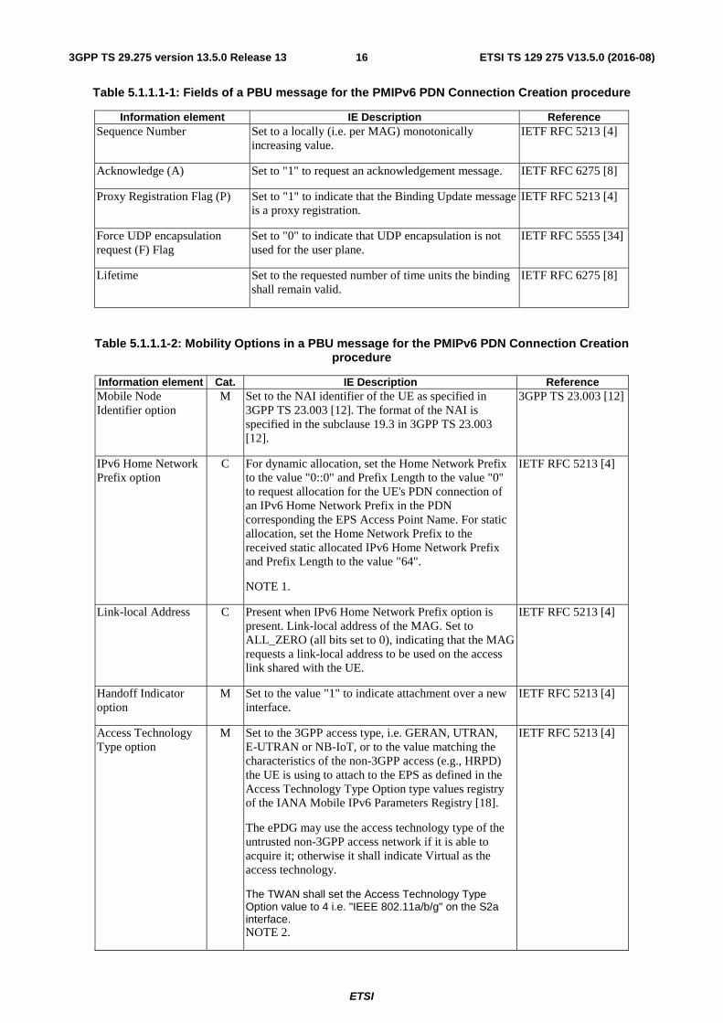
ETSI
ETSI TS 129 275 V13.5.0 (2016-08)163GPP TS 29.275 version 13.5.0 Release 13
Table 5.1.1.1-1: Fields of a PBU message for the PMIPv6 PDN Connection Creation procedure
Information element IE Description Reference Sequence Number Set to a locally (i.e. per MAG) monotonically
increasing value. IETF RFC 5213 [4]
Acknowledge (A) Set to "1" to request an acknowledgement message. IETF RFC 6275 [8]
Proxy Registration Flag (P) Set to "1" to indicate that the Binding Update message is a proxy registration.
IETF RFC 5213 [4]
Force UDP encapsulation request (F) Flag
Set to "0" to indicate that UDP encapsulation is not used for the user plane.
IETF RFC 5555 [34]
Lifetime Set to the requested number of time units the binding shall remain valid.
IETF RFC 6275 [8]
Table 5.1.1.1-2: Mobility Options in a PBU message for the PMIPv6 PDN Connection Creation procedure
Information element Cat. IE Description Reference Mobile Node Identifier option
M Set to the NAI identifier of the UE as specified in 3GPP TS 23.003 [12]. The format of the NAI is specified in the subclause 19.3 in 3GPP TS 23.003 [12].
3GPP TS 23.003 [12]
IPv6 Home Network Prefix option
C For dynamic allocation, set the Home Network Prefix to the value "0::0" and Prefix Length to the value "0" to request allocation for the UE's PDN connection of an IPv6 Home Network Prefix in the PDN corresponding the EPS Access Point Name. For static allocation, set the Home Network Prefix to the received static allocated IPv6 Home Network Prefix and Prefix Length to the value "64".
NOTE 1.
IETF RFC 5213 [4]
Link-local Address C Present when IPv6 Home Network Prefix option is present. Link-local address of the MAG. Set to ALL_ZERO (all bits set to 0), indicating that the MAG requests a link-local address to be used on the access link shared with the UE.
IETF RFC 5213 [4]
Handoff Indicator option
M Set to the value "1" to indicate attachment over a new interface.
IETF RFC 5213 [4]
Access Technology Type option
M Set to the 3GPP access type, i.e. GERAN, UTRAN, E-UTRAN or NB-IoT, or to the value matching the characteristics of the non-3GPP access (e.g., HRPD) the UE is using to attach to the EPS as defined in the Access Technology Type Option type values registry of the IANA Mobile IPv6 Parameters Registry [18].
The ePDG may use the access technology type of the untrusted non-3GPP access network if it is able to acquire it; otherwise it shall indicate Virtual as the access technology.
The TWAN shall set the Access Technology Type Option value to 4 i.e. "IEEE 802.11a/b/g" on the S2a interface. NOTE 2.
IETF RFC 5213 [4]
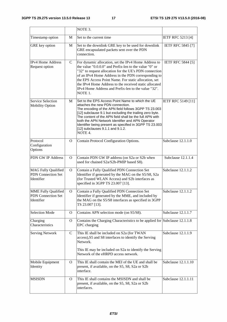
ETSI
ETSI TS 129 275 V13.5.0 (2016-08)173GPP TS 29.275 version 13.5.0 Release 13
NOTE 3.
Timestamp option M Set to the current time IETF RFC 5213 [4]
GRE key option M Set to the downlink GRE key to be used for downlink GRE encapsulated packets sent over the PDN connection.
IETF RFC 5845 [7]
IPv4 Home Address Request option
C For dynamic allocation, set the IPv4 Home Address to the value "0.0.0.0" and Prefix-len to the value "0" or "32" to request allocation for the UE's PDN connection of an IPv4 Home Address in the PDN corresponding to the EPS Access Point Name. For static allocation, set the IPv4 Home Address to the received static allocated IPv4 Home Address and Prefix-len to the value "32". NOTE 1.
IETF RFC 5844 [5]
Service Selection Mobility Option
M Set to the EPS Access Point Name to which the UE attaches the new PDN connection. The encoding of the APN field follows 3GPP TS 23.003 [12] subclause 9.1 but excluding the trailing zero byte. The content of the APN field shall be the full APN with both the APN Network Identifier and APN Operator Identifier being present as specified in 3GPP TS 23.003 [12] subclauses 9.1.1 and 9.1.2. NOTE 4.
IETF RFC 5149 [11]
Protocol Configuration Options
O Contain Protocol Configuration Options. Subclause 12.1.1.0
PDN GW IP Address O Contain PDN GW IP address (on S2a or S2b when used for chained S2a/S2b-PMIP based S8).
Subclause 12.1.1.4
MAG Fully Qualified PDN Connection Set Identifier
O Contain a Fully Qualified PDN Connection Set Identifier if generated by the MAG on the S5/S8, S2a (for Trusted WLAN Access) and S2b interfaces as specified in 3GPP TS 23.007 [13].
Subclause 12.1.1.2
MME Fully Qualified PDN Connection Set Identifier
O Contain a Fully Qualified PDN Connection Set Identifier if generated by the MME, and included by the MAG on the S5/S8 interfaces as specified in 3GPP TS 23.007 [13].
Subclause 12.1.1.2
Selection Mode O Contains APN selection mode (on S5/S8). Subclause 12.1.1.7
Charging Characteristics
O Contains the Charging Characteristics to be applied for EPC charging
Subclause 12.1.1.8
Serving Network C This IE shall be included on S2a (for TWAN access),S5 and S8 interfaces to identify the Serving Network.
This IE may be included on S2a to identify the Serving Network of the eHRPD access network.
Subclause 12.1.1.9
Mobile Equipment Identity
O This IE shall contain the MEI of the UE and shall be present, if available, on the S5, S8, S2a or S2b interface.
Subclause 12.1.1.10
MSISDN O This IE shall contains the MSISDN and shall be present, if available, on the S5, S8, S2a or S2b interfaces.
Subclause 12.1.1.11
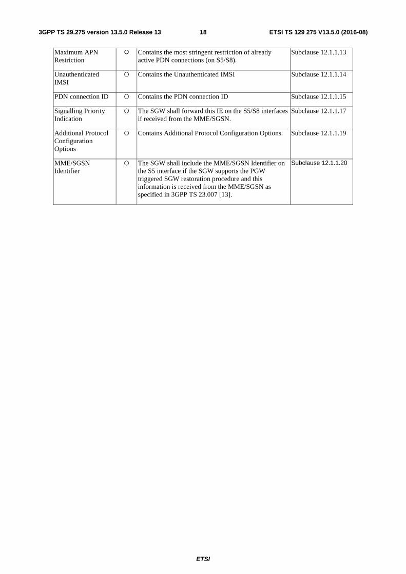
ETSI
ETSI TS 129 275 V13.5.0 (2016-08)183GPP TS 29.275 version 13.5.0 Release 13
Maximum APN Restriction
O Contains the most stringent restriction of already active PDN connections (on S5/S8).
Subclause 12.1.1.13
Unauthenticated IMSI
O Contains the Unauthenticated IMSI Subclause 12.1.1.14
PDN connection ID O Contains the PDN connection ID Subclause 12.1.1.15
Signalling Priority Indication
O The SGW shall forward this IE on the S5/S8 interfaces if received from the MME/SGSN.
Subclause 12.1.1.17
Additional Protocol Configuration Options
O Contains Additional Protocol Configuration Options. Subclause 12.1.1.19
MME/SGSN Identifier
O The SGW shall include the MME/SGSN Identifier on the S5 interface if the SGW supports the PGW triggered SGW restoration procedure and this information is received from the MME/SGSN as specified in 3GPP TS 23.007 [13].
Subclause 12.1.1.20
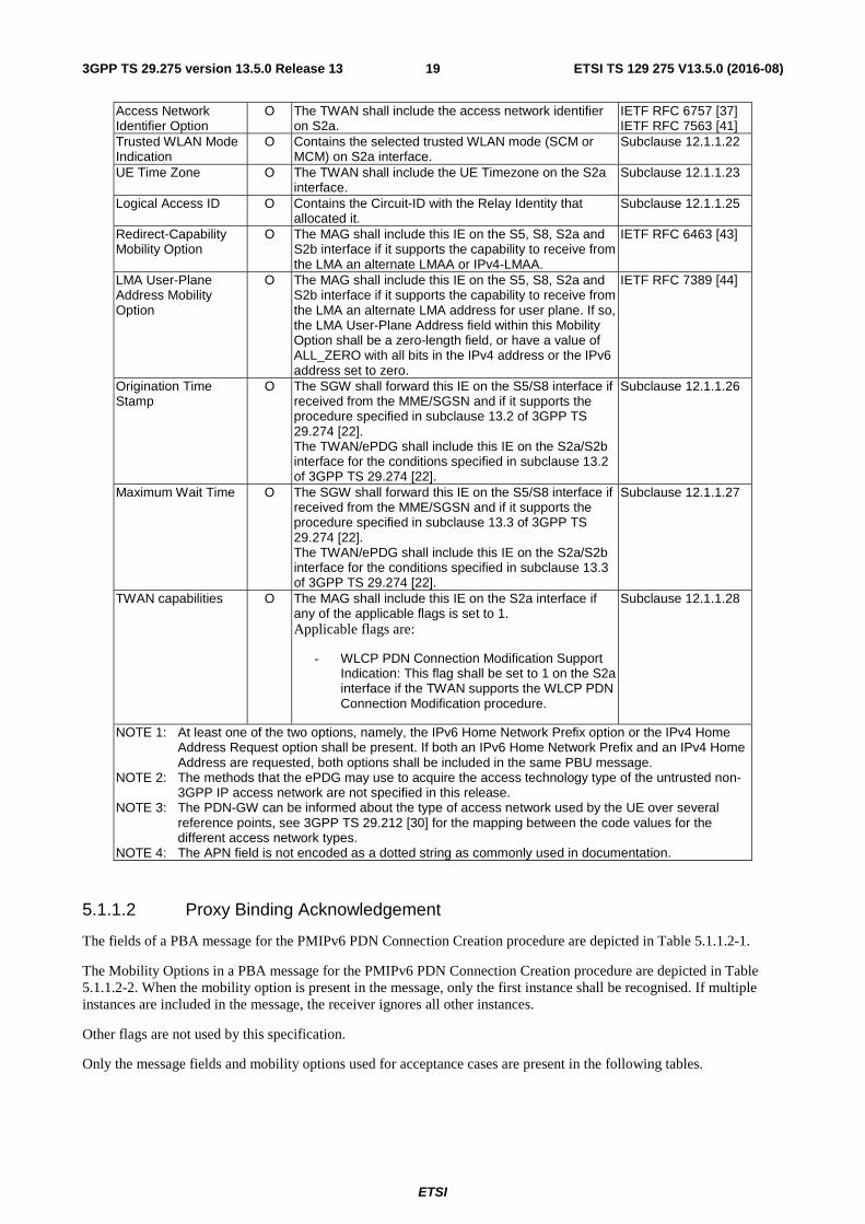
ETSI
ETSI TS 129 275 V13.5.0 (2016-08)193GPP TS 29.275 version 13.5.0 Release 13
Access Network Identifier Option
O The TWAN shall include the access network identifier on S2a.
IETF RFC 6757 [37] IETF RFC 7563 [41]
Trusted WLAN Mode Indication
O Contains the selected trusted WLAN mode (SCM or MCM) on S2a interface.
Subclause 12.1.1.22
UE Time Zone O The TWAN shall include the UE Timezone on the S2a interface.
Subclause 12.1.1.23
Logical Access ID O Contains the Circuit-ID with the Relay Identity that allocated it.
Subclause 12.1.1.25
Redirect-Capability Mobility Option
O The MAG shall include this IE on the S5, S8, S2a and S2b interface if it supports the capability to receive from the LMA an alternate LMAA or IPv4-LMAA.
IETF RFC 6463 [43]
LMA User-Plane Address Mobility Option
O The MAG shall include this IE on the S5, S8, S2a and S2b interface if it supports the capability to receive from the LMA an alternate LMA address for user plane. If so, the LMA User-Plane Address field within this Mobility Option shall be a zero-length field, or have a value of ALL_ZERO with all bits in the IPv4 address or the IPv6 address set to zero.
IETF RFC 7389 [44]
Origination Time Stamp
O The SGW shall forward this IE on the S5/S8 interface if received from the MME/SGSN and if it supports the procedure specified in subclause 13.2 of 3GPP TS 29.274 [22]. The TWAN/ePDG shall include this IE on the S2a/S2b interface for the conditions specified in subclause 13.2 of 3GPP TS 29.274 [22].
Subclause 12.1.1.26
Maximum Wait Time O The SGW shall forward this IE on the S5/S8 interface if received from the MME/SGSN and if it supports the procedure specified in subclause 13.3 of 3GPP TS 29.274 [22]. The TWAN/ePDG shall include this IE on the S2a/S2b interface for the conditions specified in subclause 13.3 of 3GPP TS 29.274 [22].
Subclause 12.1.1.27
TWAN capabilities O The MAG shall include this IE on the S2a interface if any of the applicable flags is set to 1. Applicable flags are:
- WLCP PDN Connection Modification Support Indication: This flag shall be set to 1 on the S2a interface if the TWAN supports the WLCP PDN Connection Modification procedure.
Subclause 12.1.1.28
NOTE 1: At least one of the two options, namely, the IPv6 Home Network Prefix option or the IPv4 Home Address Request option shall be present. If both an IPv6 Home Network Prefix and an IPv4 Home Address are requested, both options shall be included in the same PBU message.
NOTE 2: The methods that the ePDG may use to acquire the access technology type of the untrusted non-3GPP IP access network are not specified in this release.
NOTE 3: The PDN-GW can be informed about the type of access network used by the UE over several reference points, see 3GPP TS 29.212 [30] for the mapping between the code values for the different access network types.
NOTE 4: The APN field is not encoded as a dotted string as commonly used in documentation.
5.1.1.2 Proxy Binding Acknowledgement
The fields of a PBA message for the PMIPv6 PDN Connection Creation procedure are depicted in Table 5.1.1.2-1.
The Mobility Options in a PBA message for the PMIPv6 PDN Connection Creation procedure are depicted in Table 5.1.1.2-2. When the mobility option is present in the message, only the first instance shall be recognised. If multiple instances are included in the message, the receiver ignores all other instances.
Other flags are not used by this specification.
Only the message fields and mobility options used for acceptance cases are present in the following tables.
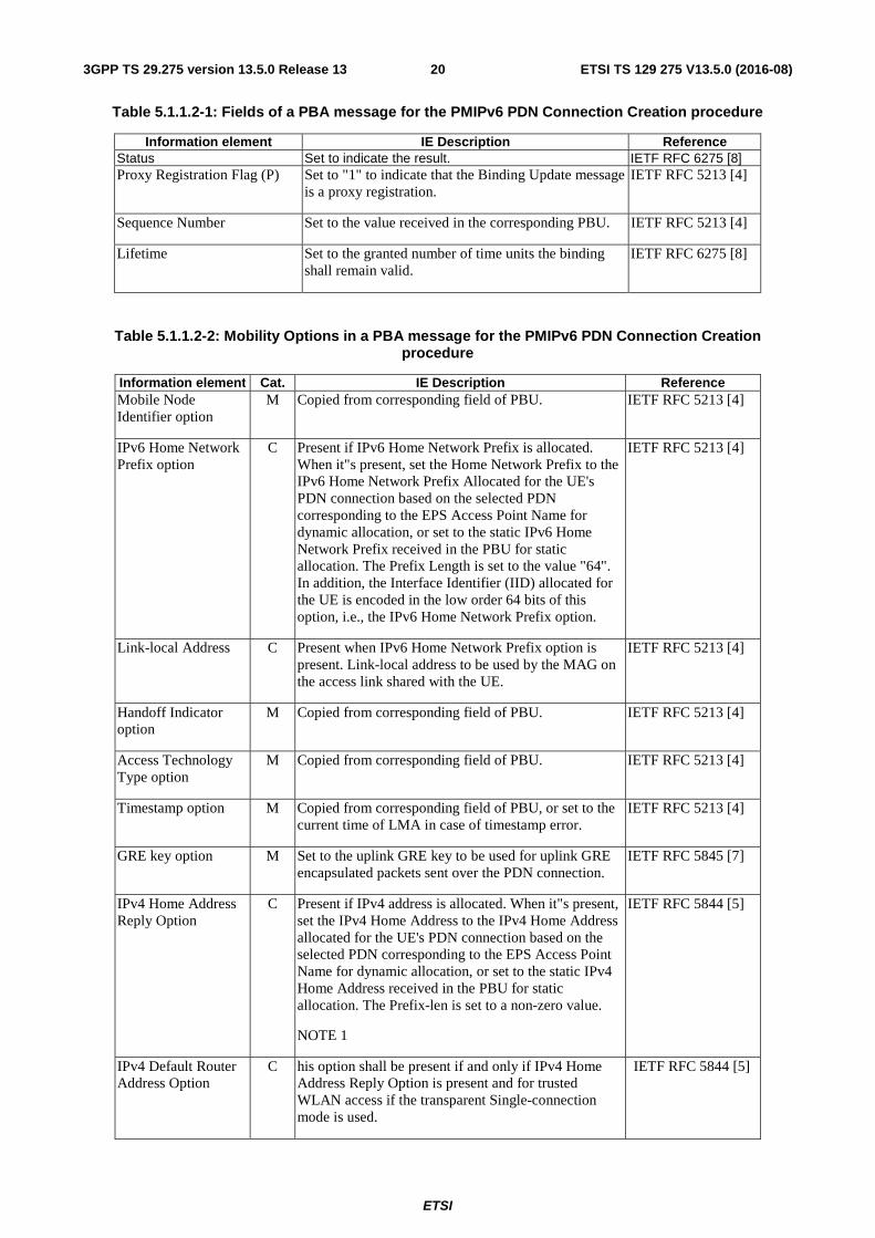
ETSI
ETSI TS 129 275 V13.5.0 (2016-08)203GPP TS 29.275 version 13.5.0 Release 13
Table 5.1.1.2-1: Fields of a PBA message for the PMIPv6 PDN Connection Creation procedure
Information element IE Description Reference Status Set to indicate the result. IETF RFC 6275 [8] Proxy Registration Flag (P) Set to "1" to indicate that the Binding Update message
is a proxy registration. IETF RFC 5213 [4]
Sequence Number Set to the value received in the corresponding PBU. IETF RFC 5213 [4]
Lifetime Set to the granted number of time units the binding shall remain valid.
IETF RFC 6275 [8]
Table 5.1.1.2-2: Mobility Options in a PBA message for the PMIPv6 PDN Connection Creation procedure
Information element Cat. IE Description Reference Mobile Node Identifier option
M Copied from corresponding field of PBU. IETF RFC 5213 [4]
IPv6 Home Network Prefix option
C Present if IPv6 Home Network Prefix is allocated. When it"s present, set the Home Network Prefix to the IPv6 Home Network Prefix Allocated for the UE's PDN connection based on the selected PDN corresponding to the EPS Access Point Name for dynamic allocation, or set to the static IPv6 Home Network Prefix received in the PBU for static allocation. The Prefix Length is set to the value "64". In addition, the Interface Identifier (IID) allocated for the UE is encoded in the low order 64 bits of this option, i.e., the IPv6 Home Network Prefix option.
IETF RFC 5213 [4]
Link-local Address C Present when IPv6 Home Network Prefix option is present. Link-local address to be used by the MAG on the access link shared with the UE.
IETF RFC 5213 [4]
Handoff Indicator option
M Copied from corresponding field of PBU. IETF RFC 5213 [4]
Access Technology Type option
M Copied from corresponding field of PBU. IETF RFC 5213 [4]
Timestamp option M Copied from corresponding field of PBU, or set to the current time of LMA in case of timestamp error.
IETF RFC 5213 [4]
GRE key option M Set to the uplink GRE key to be used for uplink GRE encapsulated packets sent over the PDN connection.
IETF RFC 5845 [7]
IPv4 Home Address Reply Option
C Present if IPv4 address is allocated. When it"s present, set the IPv4 Home Address to the IPv4 Home Address allocated for the UE's PDN connection based on the selected PDN corresponding to the EPS Access Point Name for dynamic allocation, or set to the static IPv4 Home Address received in the PBU for static allocation. The Prefix-len is set to a non-zero value.
NOTE 1
IETF RFC 5844 [5]
IPv4 Default Router Address Option
C his option shall be present if and only if IPv4 Home Address Reply Option is present and for trusted WLAN access if the transparent Single-connection mode is used.
IETF RFC 5844 [5]
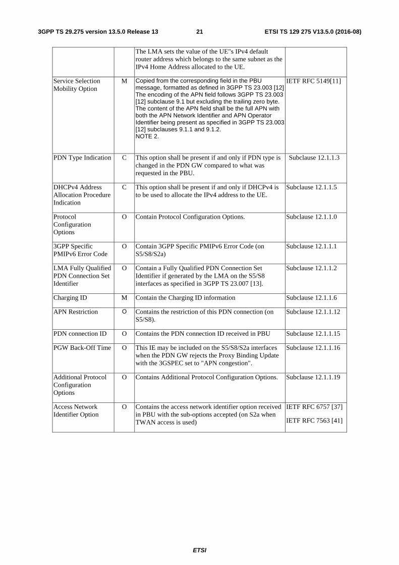
ETSI
ETSI TS 129 275 V13.5.0 (2016-08)213GPP TS 29.275 version 13.5.0 Release 13
The LMA sets the value of the UE"s IPv4 default router address which belongs to the same subnet as the IPv4 Home Address allocated to the UE.
Service Selection Mobility Option
M Copied from the corresponding field in the PBU message, formatted as defined in 3GPP TS 23.003 [12] The encoding of the APN field follows 3GPP TS 23.003 [12] subclause 9.1 but excluding the trailing zero byte. The content of the APN field shall be the full APN with both the APN Network Identifier and APN Operator Identifier being present as specified in 3GPP TS 23.003 [12] subclauses 9.1.1 and 9.1.2. NOTE 2.
IETF RFC 5149[11]
PDN Type Indication C This option shall be present if and only if PDN type is changed in the PDN GW compared to what was requested in the PBU.
Subclause 12.1.1.3
DHCPv4 Address Allocation Procedure Indication
C This option shall be present if and only if DHCPv4 is to be used to allocate the IPv4 address to the UE.
Subclause 12.1.1.5
Protocol Configuration Options
O Contain Protocol Configuration Options. Subclause 12.1.1.0
3GPP Specific PMIPv6 Error Code
O Contain 3GPP Specific PMIPv6 Error Code (on S5/S8/S2a)
Subclause 12.1.1.1
LMA Fully Qualified PDN Connection Set Identifier
O Contain a Fully Qualified PDN Connection Set Identifier if generated by the LMA on the S5/S8 interfaces as specified in 3GPP TS 23.007 [13].
Subclause 12.1.1.2
Charging ID M Contain the Charging ID information Subclause 12.1.1.6
APN Restriction O Contains the restriction of this PDN connection (on S5/S8).
Subclause 12.1.1.12
PDN connection ID O Contains the PDN connection ID received in PBU Subclause 12.1.1.15
PGW Back-Off Time O This IE may be included on the S5/S8/S2a interfaces when the PDN GW rejects the Proxy Binding Update with the 3GSPEC set to "APN congestion".
Subclause 12.1.1.16
Additional Protocol Configuration Options
O Contains Additional Protocol Configuration Options. Subclause 12.1.1.19
Access Network Identifier Option
O Contains the access network identifier option received in PBU with the sub-options accepted (on S2a when TWAN access is used)
IETF RFC 6757 [37]
IETF RFC 7563 [41]
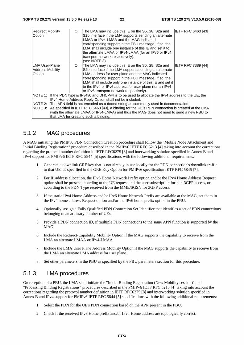
ETSI
ETSI TS 129 275 V13.5.0 (2016-08)223GPP TS 29.275 version 13.5.0 Release 13
Redirect Mobility Option
O The LMA may include this IE on the S5, S8, S2a and S2b interface if the LMA supports sending an alternate LMAA or IPv4-LMAA and the MAG indicated corresponding support in the PBU message. If so, the LMA shall include one instance of this IE and set it to the alternate LMAA or IPv4-LMAA (for an IPv6 or IPv4 transport network respectively). (see NOTE 3)
IETF RFC 6463 [43]
LMA User-Plane Address Mobility Option
O The LMA may include this IE on the S5, S8, S2a and S2b interface if the LMA supports sending an alternate LMA address for user plane and the MAG indicated corresponding support in the PBU message. If so, the LMA shall include only one instance of this IE and set it to the IPv4 or IPv6 address for user plane (for an IPv4 or IPv6 transport network respectively).
IETF RFC 7389 [44]
NOTE 1: If the PDN type is IPv4v6 and DHCPv4 is to be used to allocate the IPv4 address to the UE, the IPv4 Home Address Reply Option shall not be included.
NOTE 2: The APN field is not encoded as a dotted string as commonly used in documentation. NOTE 3: As specified in IETF RFC 6463 [43], a binding for the UE's PDN connection is created at the LMA
(with the alternate LMAA or IPv4-LMAA) and thus the MAG does not need to send a new PBU to that LMA for creating such a binding.
5.1.2 MAG procedures
A MAG initiating the PMIPv6 PDN Connection Creation procedure shall follow the "Mobile Node Attachment and Initial Binding Registration" procedure described in the PMIPv6 IETF RFC 5213 [4] taking into account the corrections regarding the protocol number definition in IETF RFC6275 [8] and interworking solution specified in Annex B and IPv4 support for PMIPv6 IETF RFC 5844 [5] specifications with the following additional requirements:
1. Generate a downlink GRE key that is not already in use locally for the PDN connection's downlink traffic to that UE, as specified in the GRE Key Option for PMIPv6 specification IETF RFC 5845 [7].
2. For IP address allocation, the IPv6 Home Network Prefix option and/or the IPv4 Home Address Request option shall be present according to the UE request and the user subscription for non-3GPP access, or according to the PDN Type received from the MME/SGSN for 3GPP access.
3. If the static IPv4 Home Address and/or IPv6 Home Network Prefix are available at the MAG, set them in the IPv4 home address Request option and/or the IPv6 home prefix option in the PBU.
4. Optionally, assign a Fully Qualified PDN Connection Set Identifier that identifies a set of PDN connections belonging to an arbitrary number of UEs.
5. Provide a PDN connection ID, if multiple PDN connections to the same APN function is supported by the MAG.
6. Include the Redirect-Capability Mobility Option if the MAG supports the capability to receive from the LMA an alternate LMAA or IPv4-LMAA.
7. Include the LMA User Plane Address Mobility Option if the MAG supports the capability to receive from the LMA an alternate LMA address for user plane.
8. Set other parameters in the PBU as specified by the PBU parameters section for this procedure.
5.1.3 LMA procedures
On reception of a PBU, the LMA shall initiate the "Initial Binding Registration (New Mobility session)" and "Processing Binding Registrations" procedures described in the PMIPv6 IETF RFC 5213 [4] taking into account the corrections regarding the protocol number definition in IETF RFC6275 [8] and interworking solution specified in Annex B and IPv4 support for PMIPv6 IETF RFC 5844 [5] specifications with the following additional requirements:
1. Select the PDN for the UE's PDN connection based on the APN present in the PBU.
2. Check if the received IPv6 Home prefix and/or IPv4 Home address are topologically correct.
ETSI
ETSI TS 129 275 V13.5.0 (2016-08)233GPP TS 29.275 version 13.5.0 Release 13
3. If no static IPv6 Home Network Prefix and/or IPv4 Home Address were received in the PBU, allocate the IPv6 Home Network Prefix and/or an IPv4 Home Address for the selected PDN.
4. If a PCO with value IPv4 Address Allocation via DHCPv4 is present in the PBU,
- if the LMA allocates an IPv4 address, it shall include the IPv4 Home Address Reply Option in the PBA message
- if the LMA allocates an IPv6 prefix, the LMA shall not allocate an IPv4 address and shall not include the IPv4 Home Address Reply Option in the PBA message
5. Generate a uplink GRE key that is not already in use locally for the PDN connection's uplink traffic from that UE, as specified in the GRE Key Option for PMIPv6 specification IETF RFC 5845 [7].
6. Assign to the UE an IPv6 Interface Identifier to allow formation of an UE Link Local Address from the well-known link local address prefix (fe80::/64).
7. Optionally, assign a Fully Qualified PDN Connection Set Identifier that identifies a set of PDN connections belonging to an arbitrary number of UEs.
8. If PDN connection ID was recevied in the PBU message,
- the LMA includes the recevied a PDN connection ID in the PBA message, if the multiple PDN connections to the same APN function is supported by the LMA; or
- the LMA ignores the received PDN connection ID and does not include it in the PBA message , if the multiple PDN connections to the same APN function is not supported by the LMA.
9. If the Redirect-Capability Mobility Option was received in the PBU message, optionally assign an alternate LMAA or IPv4-LMAA.
10. If the LMA User Plane Address Mobility Option was received in the PBU message, optionally assign an alternate LMA address for user plane.
11. Set parameters in the PBA as specified by the PBA parameters section for this procedure.
5.2 Proxy Mobile IPv6 PDN Connection Lifetime Extension procedure
5.2.1 General
The PMIPv6 PDN Connection Lifetime Extension procedure is initiated by the node acting as a MAG to prolong the lifetime of an existing PDN connection with the node acting as an LMA for an UE that is already attached. This procedure may also be used when the MME is relocated and the MAG remains unchanged (see 3GPP TS 23.007 [13]). The procedure starts with the MAG sending a PBU to the LMA to extend the binding lifetime for the UE's PDN connection. The LMA confirms that the binding lifetime is extended by sending a PBA to the MAG.
5.2.1.1 Proxy Binding Update
The fields of a PBU message for the PMIPv6 PDN Connection Lifetime Extension procedure are depicted in Table 5.2.1.1-1.
The Mobility Options in a PBU message for the PMIPv6 PDN Connection Lifetime Extension procedure are depicted in Table 5.2.1.1-2. When the mobility option is present in the message, only the first instance shall be recognised. If multiple instances are included in the message, the receiver ignores all other instances.
Other flags are not used by this specification.
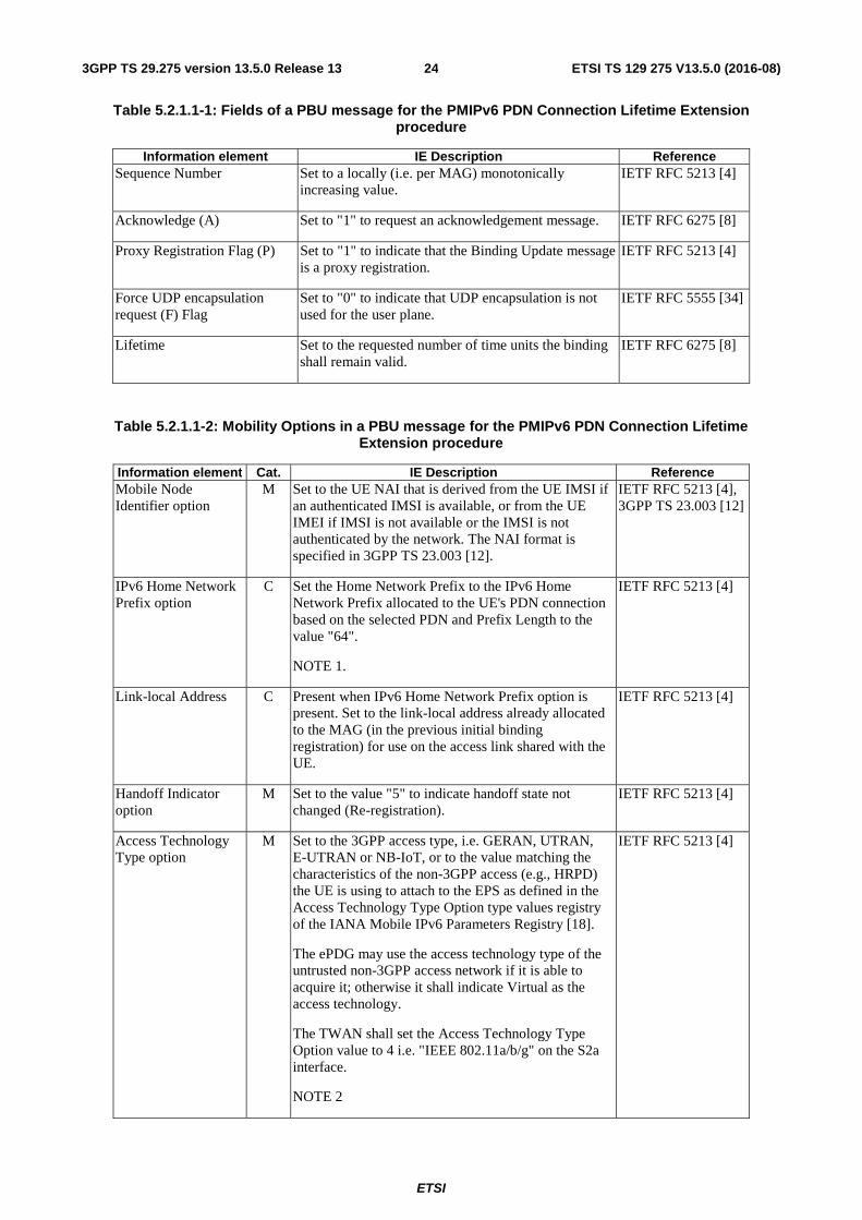
ETSI
ETSI TS 129 275 V13.5.0 (2016-08)243GPP TS 29.275 version 13.5.0 Release 13
Table 5.2.1.1-1: Fields of a PBU message for the PMIPv6 PDN Connection Lifetime Extension procedure
Information element IE Description Reference Sequence Number Set to a locally (i.e. per MAG) monotonically
increasing value. IETF RFC 5213 [4]
Acknowledge (A) Set to "1" to request an acknowledgement message. IETF RFC 6275 [8]
Proxy Registration Flag (P) Set to "1" to indicate that the Binding Update message is a proxy registration.
IETF RFC 5213 [4]
Force UDP encapsulation request (F) Flag
Set to "0" to indicate that UDP encapsulation is not used for the user plane.
IETF RFC 5555 [34]
Lifetime Set to the requested number of time units the binding shall remain valid.
IETF RFC 6275 [8]
Table 5.2.1.1-2: Mobility Options in a PBU message for the PMIPv6 PDN Connection Lifetime Extension procedure
Information element Cat. IE Description Reference Mobile Node Identifier option
M Set to the UE NAI that is derived from the UE IMSI if an authenticated IMSI is available, or from the UE IMEI if IMSI is not available or the IMSI is not authenticated by the network. The NAI format is specified in 3GPP TS 23.003 [12].
IETF RFC 5213 [4], 3GPP TS 23.003 [12]
IPv6 Home Network Prefix option
C Set the Home Network Prefix to the IPv6 Home Network Prefix allocated to the UE's PDN connection based on the selected PDN and Prefix Length to the value "64".
NOTE 1.
IETF RFC 5213 [4]
Link-local Address C Present when IPv6 Home Network Prefix option is present. Set to the link-local address already allocated to the MAG (in the previous initial binding registration) for use on the access link shared with the UE.
IETF RFC 5213 [4]
Handoff Indicator option
M Set to the value "5" to indicate handoff state not changed (Re-registration).
IETF RFC 5213 [4]
Access Technology Type option
M Set to the 3GPP access type, i.e. GERAN, UTRAN, E-UTRAN or NB-IoT, or to the value matching the characteristics of the non-3GPP access (e.g., HRPD) the UE is using to attach to the EPS as defined in the Access Technology Type Option type values registry of the IANA Mobile IPv6 Parameters Registry [18].
The ePDG may use the access technology type of the untrusted non-3GPP access network if it is able to acquire it; otherwise it shall indicate Virtual as the access technology.
The TWAN shall set the Access Technology Type Option value to 4 i.e. "IEEE 802.11a/b/g" on the S2a interface.
NOTE 2
IETF RFC 5213 [4]
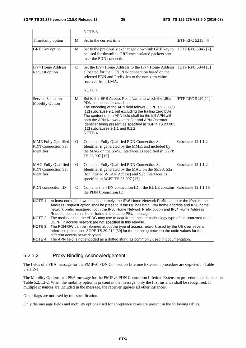
ETSI
ETSI TS 129 275 V13.5.0 (2016-08)253GPP TS 29.275 version 13.5.0 Release 13
NOTE 3
Timestamp option M Set to the current time IETF RFC 5213 [4]
GRE Key option M Set to the previously exchanged downlink GRE key to be used for downlink GRE encapsulated packets sent over the PDN connection.
IETF RFC 5845 [7]
IPv4 Home Address Request option
C Set the IPv4 Home Address to the IPv4 Home Address allocated for the UE's PDN connection based on the selected PDN and Prefix-len to the non-zero value received from LMA.
NOTE 1.
IETF RFC 5844 [5]
Service Selection Mobility Option
M Set to the EPS Access Point Name to which the UE's PDN connection is attached. The encoding of the APN field follows 3GPP TS 23.003 [12] subclause 9.1 but excluding the trailing zero byte. The content of the APN field shall be the full APN with both the APN Network Identifier and APN Operator Identifier being present as specified in 3GPP TS 23.003 [12] subclauses 9.1.1 and 9.1.2. NOTE 4.
IETF RFC 5149[11]
MME Fully Qualified PDN Connection Set Identifier
O Contain a Fully Qualified PDN Connection Set Identifier if generated by the MME, and included by the MAG on the S5/S8 interfaces as specified in 3GPP TS 23.007 [13].
Subclause 12.1.1.2
MAG Fully Qualified PDN Connection Set Identifier
O Contain a Fully Qualified PDN Connection Set Identifier if generated by the MAG on the S5/S8, S2a (for Trusted WLAN Access) and S2b interfaces as specified in 3GPP TS 23.007 [13].
Subclause 12.1.1.2
PDN connection ID C Contains the PDN connection ID if the BULE contains the PDN Connection ID.
Subclause 12.1.1.15
NOTE 1: At least one of the two options, namely, the IPv6 Home Network Prefix option or the IPv4 Home Address Request option shall be present. If the UE has both IPv4 home address and IPv6 home network prefix registered, both the IPv6 Home Network Prefix option and IPv4 Home Address Request option shall be included in the same PBU message.
NOTE 2: The methods that the ePDG may use to acquire the access technology type of the untrusted non-3GPP IP access network are not specified in this release.
NOTE 3: The PDN-GW can be informed about the type of access network used by the UE over several reference points, see 3GPP TS 29.212 [30] for the mapping between the code values for the different access network types.
NOTE 4: The APN field is not encoded as a dotted string as commonly used in documentation.
5.2.1.2 Proxy Binding Acknowledgement
The fields of a PBA message for the PMIPv6 PDN Connection Lifetime Extension procedure are depicted in Table 5.2.1.2-1.
The Mobility Options in a PBA message for the PMIPv6 PDN Connection Lifetime Extension procedure are depicted in Table 5.2.1.2-2. When the mobility option is present in the message, only the first instance shall be recognised. If multiple instances are included in the message, the receiver ignores all other instances.
Other flags are not used by this specification.
Only the message fields and mobility options used for acceptance cases are present in the following tables.
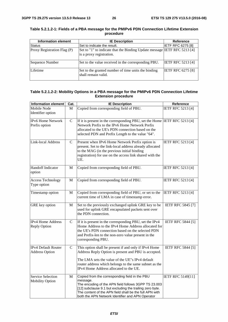
ETSI
ETSI TS 129 275 V13.5.0 (2016-08)263GPP TS 29.275 version 13.5.0 Release 13
Table 5.2.1.2-1: Fields of a PBA message for the PMIPv6 PDN Connection Lifetime Extension procedure
Information element IE Description Reference Status Set to indicate the result. IETF RFC 6275 [8] Proxy Registration Flag (P) Set to "1" to indicate that the Binding Update message
is a proxy registration. IETF RFC 5213 [4]
Sequence Number Set to the value received in the corresponding PBU. IETF RFC 5213 [4]
Lifetime Set to the granted number of time units the binding shall remain valid.
IETF RFC 6275 [8]
Table 5.2.1.2-2: Mobility Options in a PBA message for the PMIPv6 PDN Connection Lifetime Extension procedure
Information element Cat. IE Description Reference Mobile Node Identifier option
M Copied from corresponding field of PBU. IETF RFC 5213 [4]
IPv6 Home Network Prefix option
C If it is present in the corresponding PBU, set the Home Network Prefix to the IPv6 Home Network Prefix allocated to the UE's PDN connection based on the selected PDN and Prefix Length to the value "64".
IETF RFC 5213 [4]
Link-local Address C Present when IPv6 Home Network Prefix option is present. Set to the link-local address already allocated to the MAG (in the previous initial binding registration) for use on the access link shared with the UE.
IETF RFC 5213 [4]
Handoff Indicator option
M Copied from corresponding field of PBU. IETF RFC 5213 [4]
Access Technology Type option
M Copied from corresponding field of PBU. IETF RFC 5213 [4]
Timestamp option M Copied from corresponding field of PBU, or set to the current time of LMA in case of timestamp error.
IETF RFC 5213 [4]
GRE key option M Set to the previously exchanged uplink GRE key to be used for uplink GRE encapsulated packets sent over the PDN connection.
IETF RFC 5845 [7]
IPv4 Home Address Reply Option
C If it is present in the corresponding PBU, set the IPv4 Home Address to the IPv4 Home Address allocated for the UE's PDN connection based on the selected PDN and Prefix-len to the non-zero value present in the corresponding PBU.
IETF RFC 5844 [5]
IPv4 Default Router Address Option
C This option shall be present if and only if IPv4 Home Address Reply Option is present and PBU is accepted.
The LMA sets the value of the UE"s IPv4 default router address which belongs to the same subnet as the IPv4 Home Address allocated to the UE.
IETF RFC 5844 [5]
Service Selection Mobility Option
M Copied from the corresponding field in the PBU message. The encoding of the APN field follows 3GPP TS 23.003 [12] subclause 9.1 but excluding the trailing zero byte. The content of the APN field shall be the full APN with both the APN Network Identifier and APN Operator
IETF RFC 5149[11]
ETSI
ETSI TS 129 275 V13.5.0 (2016-08)273GPP TS 29.275 version 13.5.0 Release 13
Identifier being present as specified in 3GPP TS 23.003 [12] subclauses 9.1.1 and 9.1.2. NOTE 1.
3GPP Specific PMIPv6 Error Code
O Contain 3GPP Specific PMIPv6 Error Code (on S5/S8).
Subclause 12.1.1.1
LMA Fully Qualified PDN Connection Set Identifier
O Contain a Fully Qualified PDN Connection Set Identifier if generated by the LMA on the S5/S8 interfaces as specified in 3GPP TS 23.007 [13].
Subclause 12.1.1.2
PDN connection ID C Contains the PDN connection ID received in PBU Subclause 12.1.1.15
NOTE 1: The APN field is not encoded as a dotted string as commonly used in documentation.
5.2.2 MAG procedures
A MAG initiating the PMIPv6 PDN Connection Lifetime Extension procedure shall follow the "Extending Binding Lifetime" procedure described in the PMIPv6 [4] and IPv4 support for PMIPv6 [5] specifications, while parameters in the PBU are set as specified by the PBU parameters section for this procedure. When an MME FQ-CSID is received by the MAG during MME relocation, if the MAG supports the feature according to 3GPP TS 23.007 [13], it shall store the Node ID and CSID from the MME FQ-CSID for the PDN connection and forward the MME FQ-CSID to the LMA in the PBU.
5.2.3 LMA procedures
On reception of a PBU, the LMA shall initiate the "Binding Lifetime Extension without Handover" procedure as described in the PMIPv6 [4] and IPv4 support for PMIPv6 [5] specifications, while parameters in the PBA are set as specified by the PBA parameters section for this procedure. When an MME FQ-CSID is received by the LMA, if the LMA supports the feature according to 3GPP TS 23.007 [13], it shall store the Node-ID and CSID from the MME FQ-CSID in place of those previously stored for the PDN connection.
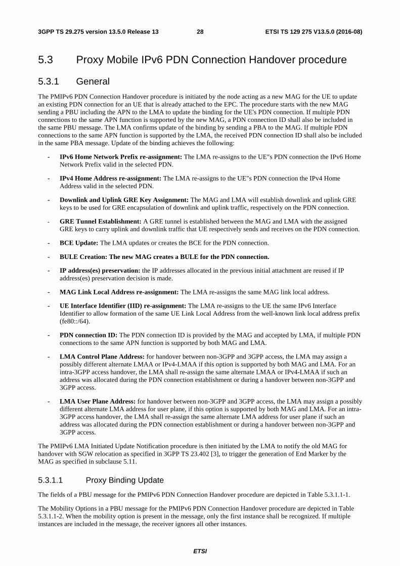
ETSI
ETSI TS 129 275 V13.5.0 (2016-08)283GPP TS 29.275 version 13.5.0 Release 13
5.3 Proxy Mobile IPv6 PDN Connection Handover procedure
5.3.1 General
The PMIPv6 PDN Connection Handover procedure is initiated by the node acting as a new MAG for the UE to update an existing PDN connection for an UE that is already attached to the EPC. The procedure starts with the new MAG sending a PBU including the APN to the LMA to update the binding for the UE's PDN connection. If multiple PDN connections to the same APN function is supported by the new MAG, a PDN connection ID shall also be included in the same PBU message. The LMA confirms update of the binding by sending a PBA to the MAG. If multiple PDN connections to the same APN function is supported by the LMA, the received PDN connection ID shall also be included in the same PBA message. Update of the binding achieves the following:
- IPv6 Home Network Prefix re-assignment: The LMA re-assigns to the UE"s PDN connection the IPv6 Home Network Prefix valid in the selected PDN.
- IPv4 Home Address re-assignment: The LMA re-assigns to the UE"s PDN connection the IPv4 Home Address valid in the selected PDN.
- Downlink and Uplink GRE Key Assignment: The MAG and LMA will establish downlink and uplink GRE keys to be used for GRE encapsulation of downlink and uplink traffic, respectively on the PDN connection.
- GRE Tunnel Establishment: A GRE tunnel is established between the MAG and LMA with the assigned GRE keys to carry uplink and downlink traffic that UE respectively sends and receives on the PDN connection.
- BCE Update: The LMA updates or creates the BCE for the PDN connection.
- BULE Creation: The new MAG creates a BULE for the PDN connection.
- IP address(es) preservation: the IP addresses allocated in the previous initial attachment are reused if IP address(es) preservation decision is made.
- MAG Link Local Address re-assignment: The LMA re-assigns the same MAG link local address.
- UE Interface Identifier (IID) re-assignment: The LMA re-assigns to the UE the same IPv6 Interface Identifier to allow formation of the same UE Link Local Address from the well-known link local address prefix (fe80::/64).
- PDN connection ID: The PDN connection ID is provided by the MAG and accepted by LMA, if multiple PDN connections to the same APN function is supported by both MAG and LMA.
- LMA Control Plane Address: for handover between non-3GPP and 3GPP access, the LMA may assign a possibly different alternate LMAA or IPv4-LMAA if this option is supported by both MAG and LMA. For an intra-3GPP access handover, the LMA shall re-assign the same alternate LMAA or IPv4-LMAA if such an address was allocated during the PDN connection establishment or during a handover between non-3GPP and 3GPP access.
- LMA User Plane Address: for handover between non-3GPP and 3GPP access, the LMA may assign a possibly different alternate LMA address for user plane, if this option is supported by both MAG and LMA. For an intra-3GPP access handover, the LMA shall re-assign the same alternate LMA address for user plane if such an address was allocated during the PDN connection establishment or during a handover between non-3GPP and 3GPP access.
The PMIPv6 LMA Initiated Update Notification procedure is then initiated by the LMA to notify the old MAG for handover with SGW relocation as specified in 3GPP TS 23.402 [3], to trigger the generation of End Marker by the MAG as specified in subclause 5.11.
5.3.1.1 Proxy Binding Update
The fields of a PBU message for the PMIPv6 PDN Connection Handover procedure are depicted in Table 5.3.1.1-1.
The Mobility Options in a PBU message for the PMIPv6 PDN Connection Handover procedure are depicted in Table 5.3.1.1-2. When the mobility option is present in the message, only the first instance shall be recognized. If multiple instances are included in the message, the receiver ignores all other instances.
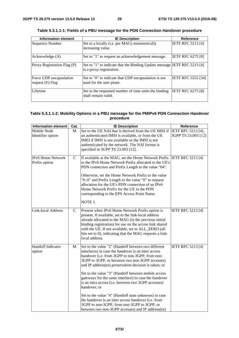
ETSI
ETSI TS 129 275 V13.5.0 (2016-08)293GPP TS 29.275 version 13.5.0 Release 13
Table 5.3.1.1-1: Fields of a PBU message for the PDN Connection Handover procedure
Information element IE Description Reference Sequence Number Set to a locally (i.e. per MAG) monotonically
increasing value. IETF RFC 5213 [4]
Acknowledge (A) Set to "1" to request an acknowledgement message. IETF RFC 6275 [8]
Proxy Registration Flag (P) Set to "1" to indicate that the Binding Update message is a proxy registration.
IETF RFC 5213 [4]
Force UDP encapsulation request (F) Flag
Set to "0" to indicate that UDP encapsulation is not used for the user plane.
IETF RFC 5555 [34]
Lifetime Set to the requested number of time units the binding shall remain valid.
IETF RFC 6275 [8]
Table 5.3.1.1-2: Mobility Options in a PBU message for the PMIPv6 PDN Connection Handover procedure
Information element Cat. IE Description Reference Mobile Node Identifier option
M Set to the UE NAI that is derived from the UE IMSI if an authenticated IMSI is available, or from the UE IMEI if IMSI is not available or the IMSI is not authenticated by the network. The NAI format is specified in 3GPP TS 23.003 [12].
IETF RFC 5213 [4], 3GPP TS 23.003 [12]
IPv6 Home Network Prefix option
C If available at the MAG, set the Home Network Prefix to the IPv6 Home Network Prefix allocated to the UE's PDN connection and Prefix Length to the value "64".
Otherwise, set the Home Network Prefix to the value "0::0" and Prefix Length to the value "0" to request allocation for the UE's PDN connection of an IPv6 Home Network Prefix for the UE in the PDN corresponding to the EPS Access Point Name.
NOTE 1.
IETF RFC 5213 [4]
Link-local Address C Present when IPv6 Home Network Prefix option is present. If available, set to the link-local address already allocated to the MAG (in the previous initial binding registration) for use on the access link shared with the UE. If not available, set to ALL_ZERO (all bits set to 0), indicating that the MAG requests a link-local address.
IETF RFC 5213 [4]
Handoff Indicator option
M Set to the value "2" (Handoff between two different interfaces) in case the handover is an inter access handover (i.e. from 3GPP to non-3GPP, from non-3GPP to 3GPP, or between two non-3GPP accesses) and IP address(es) preservation decision is taken; or
Set to the value "3" (Handoff between mobile access gateways for the same interface) in case the handover is an intra access (i.e. between two 3GPP accesses) handover; or
Set to the value "4" (Handoff state unknown) in case the handover is an inter access handover (i.e. from 3GPP to non-3GPP, from non-3GPP to 3GPP, or between two non-3GPP accesses) and IP address(es)
IETF RFC 5213 [4]
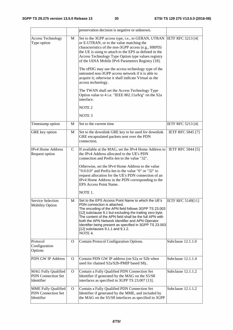
ETSI
ETSI TS 129 275 V13.5.0 (2016-08)303GPP TS 29.275 version 13.5.0 Release 13
preservation decision is negative or unknown.
Access Technology Type option
M Set to the 3GPP access type, i.e., to GERAN, UTRAN or E-UTRAN, or to the value matching the characteristics of the non-3GPP access (e.g., HRPD) the UE is using to attach to the EPS as defined in the Access Technology Type Option type values registry of the IANA Mobile IPv6 Parameters Registry [18].
The ePDG may use the access technology type of the untrusted non-3GPP access network if it is able to acquire it; otherwise it shall indicate Virtual as the access technology.
The TWAN shall set the Access Technology Type Option value to 4 i.e. "IEEE 802.11a/b/g" on the S2a interface.
NOTE 2
NOTE 3
IETF RFC 5213 [4]
Timestamp option M Set to the current time IETF RFC 5213 [4]
GRE key option M Set to the downlink GRE key to be used for downlink GRE encapsulated packets sent over the PDN connection.
IETF RFC 5845 [7]
IPv4 Home Address Request option
C If available at the MAG, set the IPv4 Home Address to the IPv4 Address allocated to the UE's PDN connection and Prefix-len to the value "32".
Otherwise, set the IPv4 Home Address to the value "0.0.0.0" and Prefix-len to the value "0" or "32" to request allocation for the UE's PDN connection of an IPv4 Home Address in the PDN corresponding to the EPS Access Point Name.
NOTE 1.
IETF RFC 5844 [5]
Service Selection Mobility Option
M Set to the EPS Access Point Name to which the UE's PDN connection is attached. The encoding of the APN field follows 3GPP TS 23.003 [12] subclause 9.1 but excluding the trailing zero byte. The content of the APN field shall be the full APN with both the APN Network Identifier and APN Operator Identifier being present as specified in 3GPP TS 23.003 [12] subclauses 9.1.1 and 9.1.2. NOTE 4.
IETF RFC 5149[11]
Protocol Configuration Options
O Contain Protocol Configuration Options. Subclause 12.1.1.0
PDN GW IP Address O Contain PDN GW IP address (on S2a or S2b when used for chained S2a/S2b-PMIP based S8)..
Subclause 12.1.1.4
MAG Fully Qualified PDN Connection Set Identifier
O Contain a Fully Qualified PDN Connection Set Identifier if generated by the MAG on the S5/S8 interfaces as specified in 3GPP TS 23.007 [13].
Subclause 12.1.1.2
MME Fully Qualified PDN Connection Set Identifier
O Contain a Fully Qualified PDN Connection Set Identifier if generated by the MME, and included by the MAG on the S5/S8 interfaces as specified in 3GPP
Subclause 12.1.1.2
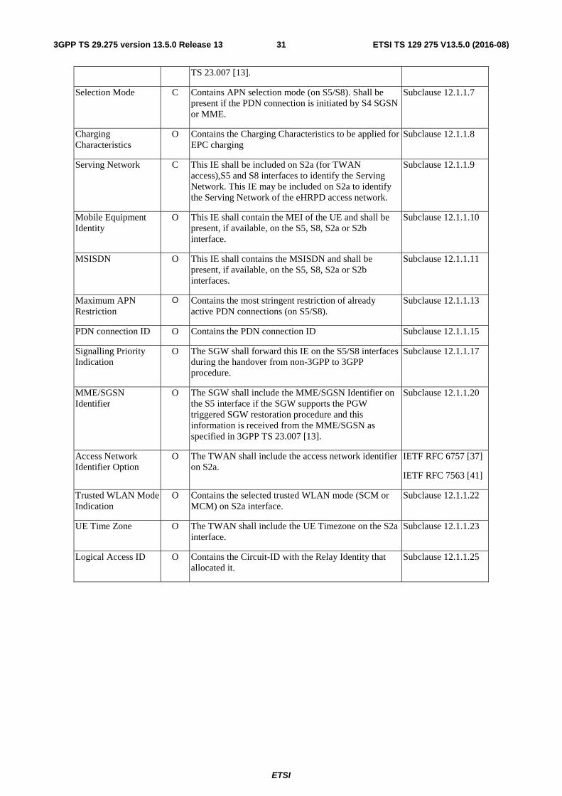
ETSI
ETSI TS 129 275 V13.5.0 (2016-08)313GPP TS 29.275 version 13.5.0 Release 13
TS 23.007 [13].
Selection Mode C Contains APN selection mode (on S5/S8). Shall be present if the PDN connection is initiated by S4 SGSN or MME.
Subclause 12.1.1.7
Charging Characteristics
O Contains the Charging Characteristics to be applied for EPC charging
Subclause 12.1.1.8
Serving Network C This IE shall be included on S2a (for TWAN access),S5 and S8 interfaces to identify the Serving Network. This IE may be included on S2a to identify the Serving Network of the eHRPD access network.
Subclause 12.1.1.9
Mobile Equipment Identity
O This IE shall contain the MEI of the UE and shall be present, if available, on the S5, S8, S2a or S2b interface.
Subclause 12.1.1.10
MSISDN O This IE shall contains the MSISDN and shall be present, if available, on the S5, S8, S2a or S2b interfaces.
Subclause 12.1.1.11
Maximum APN Restriction
O Contains the most stringent restriction of already active PDN connections (on S5/S8).
Subclause 12.1.1.13
PDN connection ID O Contains the PDN connection ID Subclause 12.1.1.15
Signalling Priority Indication
O The SGW shall forward this IE on the S5/S8 interfaces during the handover from non-3GPP to 3GPP procedure.
Subclause 12.1.1.17
MME/SGSN Identifier
O The SGW shall include the MME/SGSN Identifier on the S5 interface if the SGW supports the PGW triggered SGW restoration procedure and this information is received from the MME/SGSN as specified in 3GPP TS 23.007 [13].
Subclause 12.1.1.20
Access Network Identifier Option
O The TWAN shall include the access network identifier on S2a.
IETF RFC 6757 [37]
IETF RFC 7563 [41]
Trusted WLAN Mode Indication
O Contains the selected trusted WLAN mode (SCM or MCM) on S2a interface.
Subclause 12.1.1.22
UE Time Zone O The TWAN shall include the UE Timezone on the S2a interface.
Subclause 12.1.1.23
Logical Access ID O Contains the Circuit-ID with the Relay Identity that allocated it.
Subclause 12.1.1.25
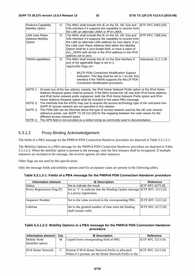
ETSI
ETSI TS 129 275 V13.5.0 (2016-08)323GPP TS 29.275 version 13.5.0 Release 13
Redirect-Capability Mobility Option
O The MAG shall include this IE on the S5, S8, S2a and S2b interface if it supports the capability to receive from the LMA an alternate LMAA or IPv4-LMAA.
IETF RFC 6463 [43]
LMA User-Plane Address Mobility Option
O The MAG shall include this IE on the S5, S8, S2a and S2b interface if it supports the capability to receive from the LMA an alternate LMA address for user plane. If so, the LMA User Plane Address field within this Mobility Option shall be a zero-length field, or have a value of ALL_ZERO with all bits in the IPv4 address or the IPv6 address set to zero.
IETF RFC 7389 [44]
TWAN capabilities O The MAG shall include this IE on the S2a interface if any of the applicable flags is set to 1. Applicable flags are:
- WLCP PDN Connection Modification Support Indication: This flag shall be set to 1 on the S2a interface if the TWAN supports the WLCP PDN Connection Modification procedure.
Subclause 12.1.1.28
NOTE 1: At least one of the two options, namely, the IPv6 Home Network Prefix option or the IPv4 Home Address Request option shall be present. If the MAG knows the UE has both IPv4 home address and IPv6 home network prefix registered, both the IPv6 Home Network Prefix option and IPv4 Home Address Request option shall be included in the same PBU message.
NOTE 2: The methods that the ePDG may use to acquire the access technology type of the untrusted non-3GPP IP access network are not specified in this release.
NOTE 3: The PDN-GW can be informed about the type of access network used by the UE over several reference points, see 3GPP TS 29.212 [30] for the mapping between the code values for the different access network types.
NOTE 4: The APN field is not encoded as a dotted string as commonly used in documentation.
5.3.1.2 Proxy Binding Acknowledgement
The fields of a PBA message for the PMIPv6 PDN Connection Handover procedure are depicted in Table 5.3.1.2-1.
The Mobility Options in a PBA message for the PMIPv6 PDN Connection Handover procedure are depicted in Table 5.3.1.2-2. When the mobility option is present in the message, only the first instance shall be recognised. If multiple instances are included in the message, the receiver ignores all other instances.
Other flags are not used by this specification.
Only the message fields and mobility options used for acceptance cases are present in the following tables.
Table 5.3.1.2-1: Fields of a PBA message for the PMIPv6 PDN Connection Handover procedure
Information element IE Description Reference Status Set to indicate the result. IETF RFC 6275 [8] Proxy Registration Flag (P) Set to "1" to indicate that the Binding Update message
is a proxy registration. IETF RFC 5213 [4]
Sequence Number Set to the value received in the corresponding PBU. IETF RFC 5213 [4]
Lifetime Set to the granted number of time units the binding shall remain valid.
IETF RFC 6275 [8]
Table 5.3.1.2-2: Mobility Options in a PBA message for the PMIPv6 PDN Connection Handover procedure
Information element Cat. IE Description Reference Mobile Node Identifier option
M Copied from corresponding field of PBU. IETF RFC 5213 [4]
IPv6 Home Network C Present if IPv6 Home Network Prefix is allocated. When it"s present, set the Home Network Prefix to the
IETF RFC 5213 [4]
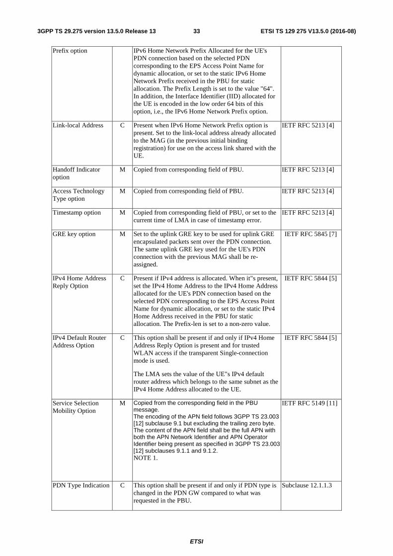
ETSI
ETSI TS 129 275 V13.5.0 (2016-08)333GPP TS 29.275 version 13.5.0 Release 13
Prefix option IPv6 Home Network Prefix Allocated for the UE's PDN connection based on the selected PDN corresponding to the EPS Access Point Name for dynamic allocation, or set to the static IPv6 Home Network Prefix received in the PBU for static allocation. The Prefix Length is set to the value "64". In addition, the Interface Identifier (IID) allocated for the UE is encoded in the low order 64 bits of this option, i.e., the IPv6 Home Network Prefix option.
Link-local Address C Present when IPv6 Home Network Prefix option is present. Set to the link-local address already allocated to the MAG (in the previous initial binding registration) for use on the access link shared with the UE.
IETF RFC 5213 [4]
Handoff Indicator option
M Copied from corresponding field of PBU. IETF RFC 5213 [4]
Access Technology Type option
M Copied from corresponding field of PBU. IETF RFC 5213 [4]
Timestamp option M Copied from corresponding field of PBU, or set to the current time of LMA in case of timestamp error.
IETF RFC 5213 [4]
GRE key option M Set to the uplink GRE key to be used for uplink GRE encapsulated packets sent over the PDN connection. The same uplink GRE key used for the UE's PDN connection with the previous MAG shall be re-assigned.
IETF RFC 5845 [7]
IPv4 Home Address Reply Option
C Present if IPv4 address is allocated. When it"s present, set the IPv4 Home Address to the IPv4 Home Address allocated for the UE's PDN connection based on the selected PDN corresponding to the EPS Access Point Name for dynamic allocation, or set to the static IPv4 Home Address received in the PBU for static allocation. The Prefix-len is set to a non-zero value.
IETF RFC 5844 [5]
IPv4 Default Router Address Option
C This option shall be present if and only if IPv4 Home Address Reply Option is present and for trusted WLAN access if the transparent Single-connection mode is used.
The LMA sets the value of the UE"s IPv4 default router address which belongs to the same subnet as the IPv4 Home Address allocated to the UE.
IETF RFC 5844 [5]
Service Selection Mobility Option
M Copied from the corresponding field in the PBU message. The encoding of the APN field follows 3GPP TS 23.003 [12] subclause 9.1 but excluding the trailing zero byte. The content of the APN field shall be the full APN with both the APN Network Identifier and APN Operator Identifier being present as specified in 3GPP TS 23.003 [12] subclauses 9.1.1 and 9.1.2. NOTE 1.
IETF RFC 5149 [11]
PDN Type Indication C This option shall be present if and only if PDN type is changed in the PDN GW compared to what was requested in the PBU.
Subclause 12.1.1.3
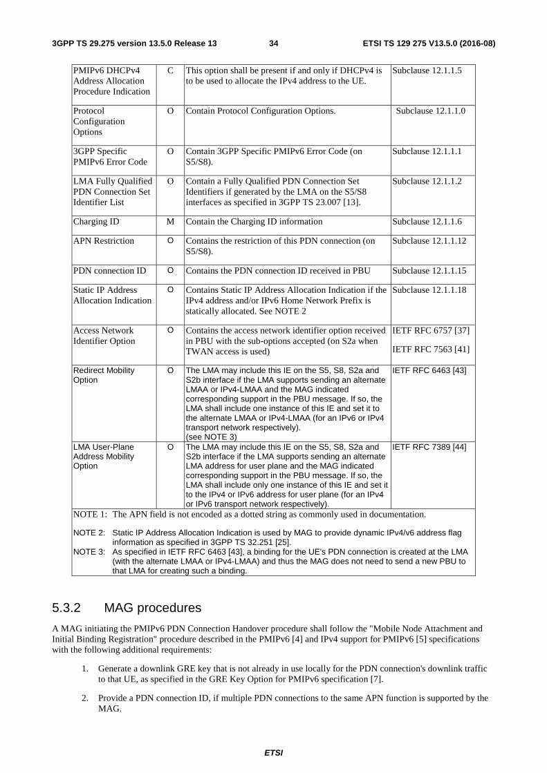
ETSI
ETSI TS 129 275 V13.5.0 (2016-08)343GPP TS 29.275 version 13.5.0 Release 13
PMIPv6 DHCPv4 Address Allocation Procedure Indication
C This option shall be present if and only if DHCPv4 is to be used to allocate the IPv4 address to the UE.
Subclause 12.1.1.5
Protocol Configuration Options
O Contain Protocol Configuration Options. Subclause 12.1.1.0
3GPP Specific PMIPv6 Error Code
O Contain 3GPP Specific PMIPv6 Error Code (on S5/S8).
Subclause 12.1.1.1
LMA Fully Qualified PDN Connection Set Identifier List
O Contain a Fully Qualified PDN Connection Set Identifiers if generated by the LMA on the S5/S8 interfaces as specified in 3GPP TS 23.007 [13].
Subclause 12.1.1.2
Charging ID M Contain the Charging ID information Subclause 12.1.1.6
APN Restriction O Contains the restriction of this PDN connection (on S5/S8).
Subclause 12.1.1.12
PDN connection ID O Contains the PDN connection ID received in PBU Subclause 12.1.1.15
Static IP Address Allocation Indication
O Contains Static IP Address Allocation Indication if the IPv4 address and/or IPv6 Home Network Prefix is statically allocated. See NOTE 2
Subclause 12.1.1.18
Access Network Identifier Option
O Contains the access network identifier option received in PBU with the sub-options accepted (on S2a when TWAN access is used)
IETF RFC 6757 [37]
IETF RFC 7563 [41]
Redirect Mobility Option
O The LMA may include this IE on the S5, S8, S2a and S2b interface if the LMA supports sending an alternate LMAA or IPv4-LMAA and the MAG indicated corresponding support in the PBU message. If so, the LMA shall include one instance of this IE and set it to the alternate LMAA or IPv4-LMAA (for an IPv6 or IPv4 transport network respectively). (see NOTE 3)
IETF RFC 6463 [43]
LMA User-Plane Address Mobility Option
O The LMA may include this IE on the S5, S8, S2a and S2b interface if the LMA supports sending an alternate LMA address for user plane and the MAG indicated corresponding support in the PBU message. If so, the LMA shall include only one instance of this IE and set it to the IPv4 or IPv6 address for user plane (for an IPv4 or IPv6 transport network respectively).
IETF RFC 7389 [44]
NOTE 1: The APN field is not encoded as a dotted string as commonly used in documentation.
NOTE 2: Static IP Address Allocation Indication is used by MAG to provide dynamic IPv4/v6 address flag information as specified in 3GPP TS 32.251 [25].
NOTE 3: As specified in IETF RFC 6463 [43], a binding for the UE's PDN connection is created at the LMA (with the alternate LMAA or IPv4-LMAA) and thus the MAG does not need to send a new PBU to that LMA for creating such a binding.
5.3.2 MAG procedures
A MAG initiating the PMIPv6 PDN Connection Handover procedure shall follow the "Mobile Node Attachment and Initial Binding Registration" procedure described in the PMIPv6 [4] and IPv4 support for PMIPv6 [5] specifications with the following additional requirements:
1. Generate a downlink GRE key that is not already in use locally for the PDN connection's downlink traffic to that UE, as specified in the GRE Key Option for PMIPv6 specification [7].
2. Provide a PDN connection ID, if multiple PDN connections to the same APN function is supported by the MAG.
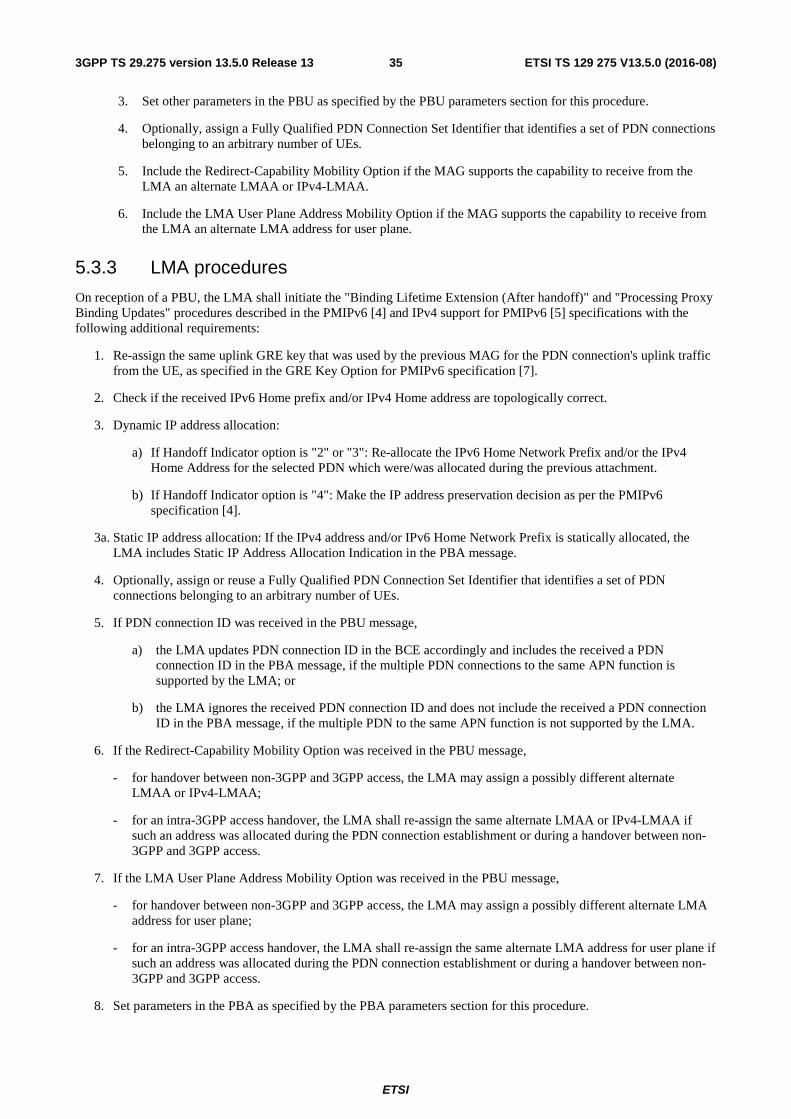
ETSI
ETSI TS 129 275 V13.5.0 (2016-08)353GPP TS 29.275 version 13.5.0 Release 13
3. Set other parameters in the PBU as specified by the PBU parameters section for this procedure.
4. Optionally, assign a Fully Qualified PDN Connection Set Identifier that identifies a set of PDN connections belonging to an arbitrary number of UEs.
5. Include the Redirect-Capability Mobility Option if the MAG supports the capability to receive from the LMA an alternate LMAA or IPv4-LMAA.
6. Include the LMA User Plane Address Mobility Option if the MAG supports the capability to receive from the LMA an alternate LMA address for user plane.
5.3.3 LMA procedures
On reception of a PBU, the LMA shall initiate the "Binding Lifetime Extension (After handoff)" and "Processing Proxy Binding Updates" procedures described in the PMIPv6 [4] and IPv4 support for PMIPv6 [5] specifications with the following additional requirements:
1. Re-assign the same uplink GRE key that was used by the previous MAG for the PDN connection's uplink traffic from the UE, as specified in the GRE Key Option for PMIPv6 specification [7].
2. Check if the received IPv6 Home prefix and/or IPv4 Home address are topologically correct.
3. Dynamic IP address allocation:
a) If Handoff Indicator option is "2" or "3": Re-allocate the IPv6 Home Network Prefix and/or the IPv4 Home Address for the selected PDN which were/was allocated during the previous attachment.
b) If Handoff Indicator option is "4": Make the IP address preservation decision as per the PMIPv6 specification [4].
3a. Static IP address allocation: If the IPv4 address and/or IPv6 Home Network Prefix is statically allocated, the LMA includes Static IP Address Allocation Indication in the PBA message.
4. Optionally, assign or reuse a Fully Qualified PDN Connection Set Identifier that identifies a set of PDN connections belonging to an arbitrary number of UEs.
5. If PDN connection ID was received in the PBU message,
a) the LMA updates PDN connection ID in the BCE accordingly and includes the received a PDN connection ID in the PBA message, if the multiple PDN connections to the same APN function is supported by the LMA; or
b) the LMA ignores the received PDN connection ID and does not include the received a PDN connection ID in the PBA message, if the multiple PDN to the same APN function is not supported by the LMA.
6. If the Redirect-Capability Mobility Option was received in the PBU message,
- for handover between non-3GPP and 3GPP access, the LMA may assign a possibly different alternate LMAA or IPv4-LMAA;
- for an intra-3GPP access handover, the LMA shall re-assign the same alternate LMAA or IPv4-LMAA if such an address was allocated during the PDN connection establishment or during a handover between non-3GPP and 3GPP access.
7. If the LMA User Plane Address Mobility Option was received in the PBU message,
- for handover between non-3GPP and 3GPP access, the LMA may assign a possibly different alternate LMA address for user plane;
- for an intra-3GPP access handover, the LMA shall re-assign the same alternate LMA address for user plane if such an address was allocated during the PDN connection establishment or during a handover between non-3GPP and 3GPP access.
8. Set parameters in the PBA as specified by the PBA parameters section for this procedure.
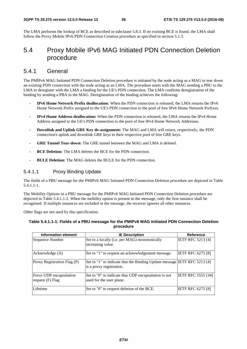
ETSI
ETSI TS 129 275 V13.5.0 (2016-08)363GPP TS 29.275 version 13.5.0 Release 13
The LMA performs the lookup of BCE as described in subclause 5.8.3. If no existing BCE is found, the LMA shall follow the Proxy Mobile IPv6 PDN Connection Creation procedure as specified in section 5.1.3.
5.4 Proxy Mobile IPv6 MAG Initiated PDN Connection Deletion procedure
5.4.1 General
The PMIPv6 MAG Initiated PDN Connection Deletion procedure is initiated by the node acting as a MAG to tear down an existing PDN connection with the node acting as an LMA. The procedure starts with the MAG sending a PBU to the LMA to deregister with the LMA a binding for the UE's PDN connection. The LMA confirms deregistration of the binding by sending a PBA to the MAG. Deregistration of the binding achieves the following:
- IPv6 Home Network Prefix deallocation: When the PDN connection is released, the LMA returns the IPv6 Home Network Prefix assigned to the UE's PDN connection to the pool of free IPv6 Home Network Prefixes.
- IPv4 Home Address deallocation: When the PDN connection is released, the LMA returns the IPv4 Home Address assigned to the UE's PDN connection to the pool of free IPv4 Home Network Addresses.
- Downlink and Uplink GRE Key de-assignment: The MAG and LMA will return, respectively, the PDN connection's uplink and downlink GRE keys to their respective pool of free GRE keys.
- GRE Tunnel Tear-down: The GRE tunnel between the MAG and LMA is deleted.
- BCE Deletion: The LMA deletes the BCE for the PDN connection.
- BULE Deletion: The MAG deletes the BULE for the PDN connection.
5.4.1.1 Proxy Binding Update
The fields of a PBU message for the PMIPv6 MAG Initiated PDN Connection Deletion procedure are depicted in Table 5.4.1.1-1.
The Mobility Options in a PBU message for the PMIPv6 MAG Initiated PDN Connection Deletion procedure are depicted in Table 5.4.1.1-2. When the mobility option is present in the message, only the first instance shall be recognised. If multiple instances are included in the message, the receiver ignores all other instances.
Other flags are not used by this specification.
Table 5.4.1.1-1: Fields of a PBU message for the PMIPv6 MAG Initiated PDN Connection Deletion procedure
Information element IE Description Reference Sequence Number Set to a locally (i.e. per MAG) monotonically
increasing value. IETF RFC 5213 [4]
Acknowledge (A) Set to "1" to request an acknowledgement message. IETF RFC 6275 [8]
Proxy Registration Flag (P) Set to "1" to indicate that the Binding Update message is a proxy registration.
IETF RFC 5213 [4]
Force UDP encapsulation request (F) Flag
Set to "0" to indicate that UDP encapsulation is not used for the user plane.
IETF RFC 5555 [34]
Lifetime Set to "0" to request deletion of the BCE. IETF RFC 6275 [8]
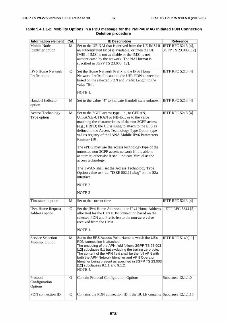
ETSI
ETSI TS 129 275 V13.5.0 (2016-08)373GPP TS 29.275 version 13.5.0 Release 13
Table 5.4.1.1-2: Mobility Options in a PBU message for the PMIPv6 MAG Initiated PDN Connection Deletion procedure
Information element Cat. IE Description Reference Mobile Node Identifier option
M Set to the UE NAI that is derived from the UE IMSI if an authenticated IMSI is available, or from the UE IMEI if IMSI is not available or the IMSI is not authenticated by the network. The NAI format is specified in 3GPP TS 23.003 [12].
IETF RFC 5213 [4], 3GPP TS 23.003 [12]
IPv6 Home Network Prefix option
C Set the Home Network Prefix to the IPv6 Home Network Prefix allocated to the UE's PDN connection based on the selected PDN and Prefix Length to the value "64".
NOTE 1.
IETF RFC 5213 [4]
Handoff Indicator option
M Set to the value "4" to indicate Handoff state unknown. IETF RFC 5213 [4]
Access Technology Type option
M Set to the 3GPP access type, i.e., to GERAN, UTRAN,E-UTRAN or NB-IoT, or to the value matching the characteristics of the non-3GPP access (e.g., HRPD) the UE is using to attach to the EPS as defined in the Access Technology Type Option type values registry of the IANA Mobile IPv6 Parameters Registry [18].
The ePDG may use the access technology type of the untrusted non-3GPP access network if it is able to acquire it; otherwise it shall indicate Virtual as the access technology.
The TWAN shall set the Access Technology Type Option value to 4 i.e. "IEEE 802.11a/b/g" on the S2a interface.
NOTE 2
NOTE 3
IETF RFC 5213 [4]
Timestamp option M Set to the current time IETF RFC 5213 [4]
IPv4 Home Request Address option
C Set the IPv4 Home Address to the IPv4 Home Address allocated for the UE's PDN connection based on the selected PDN and Prefix-len to the non-zero value received from the LMA.
NOTE 1.
IETF RFC 5844 [5]
Service Selection Mobility Option
M Set to the EPS Access Point Name to which the UE's PDN connection is attached. The encoding of the APN field follows 3GPP TS 23.003 [12] subclause 9.1 but excluding the trailing zero byte. The content of the APN field shall be the full APN with both the APN Network Identifier and APN Operator Identifier being present as specified in 3GPP TS 23.003 [12] subclauses 9.1.1 and 9.1.2. NOTE 4.
IETF RFC 5149[11]
Protocol Configuration Options
O Contain Protocol Configuration Options. Subclause 12.1.1.0
PDN connection ID C Contains the PDN connection ID if the BULE contains Subclause 12.1.1.15
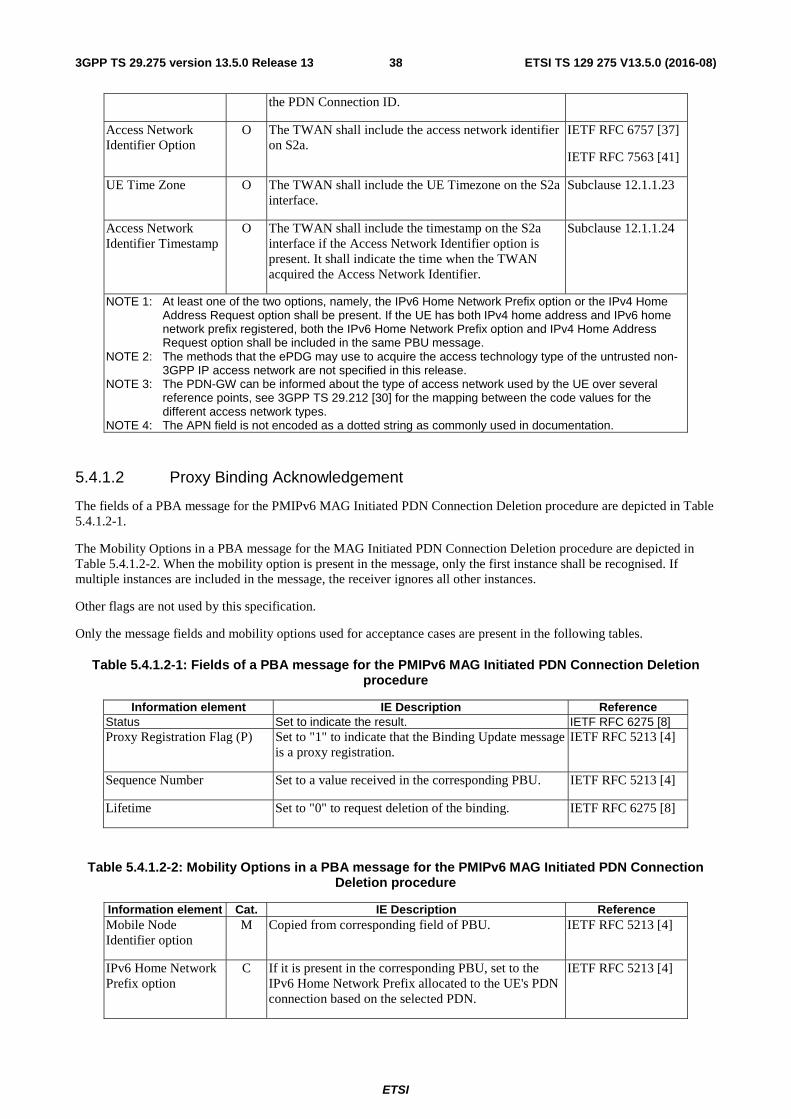
ETSI
ETSI TS 129 275 V13.5.0 (2016-08)383GPP TS 29.275 version 13.5.0 Release 13
the PDN Connection ID.
Access Network Identifier Option
O The TWAN shall include the access network identifier on S2a.
IETF RFC 6757 [37]
IETF RFC 7563 [41]
UE Time Zone O The TWAN shall include the UE Timezone on the S2a interface.
Subclause 12.1.1.23
Access Network Identifier Timestamp
O The TWAN shall include the timestamp on the S2a interface if the Access Network Identifier option is present. It shall indicate the time when the TWAN acquired the Access Network Identifier.
Subclause 12.1.1.24
NOTE 1: At least one of the two options, namely, the IPv6 Home Network Prefix option or the IPv4 Home Address Request option shall be present. If the UE has both IPv4 home address and IPv6 home network prefix registered, both the IPv6 Home Network Prefix option and IPv4 Home Address Request option shall be included in the same PBU message.
NOTE 2: The methods that the ePDG may use to acquire the access technology type of the untrusted non-3GPP IP access network are not specified in this release.
NOTE 3: The PDN-GW can be informed about the type of access network used by the UE over several reference points, see 3GPP TS 29.212 [30] for the mapping between the code values for the different access network types.
NOTE 4: The APN field is not encoded as a dotted string as commonly used in documentation.
5.4.1.2 Proxy Binding Acknowledgement
The fields of a PBA message for the PMIPv6 MAG Initiated PDN Connection Deletion procedure are depicted in Table 5.4.1.2-1.
The Mobility Options in a PBA message for the MAG Initiated PDN Connection Deletion procedure are depicted in Table 5.4.1.2-2. When the mobility option is present in the message, only the first instance shall be recognised. If multiple instances are included in the message, the receiver ignores all other instances.
Other flags are not used by this specification.
Only the message fields and mobility options used for acceptance cases are present in the following tables.
Table 5.4.1.2-1: Fields of a PBA message for the PMIPv6 MAG Initiated PDN Connection Deletion procedure
Information element IE Description Reference Status Set to indicate the result. IETF RFC 6275 [8] Proxy Registration Flag (P) Set to "1" to indicate that the Binding Update message
is a proxy registration. IETF RFC 5213 [4]
Sequence Number Set to a value received in the corresponding PBU. IETF RFC 5213 [4]
Lifetime Set to "0" to request deletion of the binding. IETF RFC 6275 [8]
Table 5.4.1.2-2: Mobility Options in a PBA message for the PMIPv6 MAG Initiated PDN Connection Deletion procedure
Information element Cat. IE Description Reference Mobile Node Identifier option
M Copied from corresponding field of PBU. IETF RFC 5213 [4]
IPv6 Home Network Prefix option
C If it is present in the corresponding PBU, set to the IPv6 Home Network Prefix allocated to the UE's PDN connection based on the selected PDN.
IETF RFC 5213 [4]
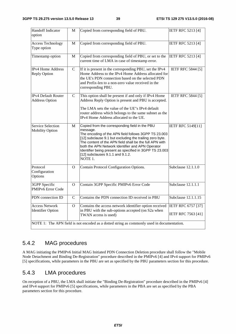
ETSI
ETSI TS 129 275 V13.5.0 (2016-08)393GPP TS 29.275 version 13.5.0 Release 13
Handoff Indicator option
M Copied from corresponding field of PBU. IETF RFC 5213 [4]
Access Technology Type option
M Copied from corresponding field of PBU. IETF RFC 5213 [4]
Timestamp option M Copied from corresponding field of PBU, or set to the current time of LMA in case of timestamp error.
IETF RFC 5213 [4]
IPv4 Home Address Reply Option
C If it is present in the corresponding PBU, set the IPv4 Home Address to the IPv4 Home Address allocated for the UE's PDN connection based on the selected PDN and Prefix-len to a non-zero value received in the corresponding PBU.
IETF RFC 5844 [5]
IPv4 Default Router Address Option
C This option shall be present if and only if IPv4 Home Address Reply Option is present and PBU is accepted.
The LMA sets the value of the UE"s IPv4 default router address which belongs to the same subnet as the IPv4 Home Address allocated to the UE.
IETF RFC 5844 [5]
Service Selection Mobility Option
M Copied from the corresponding field in the PBU message. The encoding of the APN field follows 3GPP TS 23.003 [12] subclause 9.1 but excluding the trailing zero byte. The content of the APN field shall be the full APN with both the APN Network Identifier and APN Operator Identifier being present as specified in 3GPP TS 23.003 [12] subclauses 9.1.1 and 9.1.2. NOTE 1.
IETF RFC 5149[11]
Protocol Configuration Options
O Contain Protocol Configuration Options. Subclause 12.1.1.0
3GPP Specific PMIPv6 Error Code
O Contain 3GPP Specific PMIPv6 Error Code Subclause 12.1.1.1
PDN connection ID C Contains the PDN connection ID received in PBU Subclause 12.1.1.15
Access Network Identifier Option
O Contains the access network identifier option received in PBU with the sub-options accepted (on S2a when TWAN access is used)
IETF RFC 6757 [37]
IETF RFC 7563 [41]
NOTE 1: The APN field is not encoded as a dotted string as commonly used in documentation.
5.4.2 MAG procedures
A MAG initiating the PMIPv6 Initial MAG Initiated PDN Connection Deletion procedure shall follow the "Mobile Node Detachment and Binding De-Registration" procedure described in the PMIPv6 [4] and IPv4 support for PMIPv6 [5] specifications, while parameters in the PBU are set as specified by the PBU parameters section for this procedure.
5.4.3 LMA procedures
On reception of a PBU, the LMA shall initiate the "Binding De-Registration" procedure described in the PMIPv6 [4] and IPv4 support for PMIPv6 [5] specifications, while parameters in the PBA are set as specified by the PBA parameters section for this procedure.
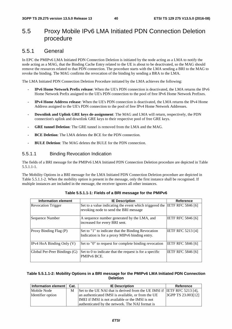
ETSI
ETSI TS 129 275 V13.5.0 (2016-08)403GPP TS 29.275 version 13.5.0 Release 13
5.5 Proxy Mobile IPv6 LMA Initiated PDN Connection Deletion procedure
5.5.1 General
In EPC the PMIPv6 LMA Initiated PDN Connection Deletion is initiated by the node acting as a LMA to notify the node acting as a MAG, that the Binding Cache Entry related to the UE is about to be deactivated, so the MAG should remove the resources related to that PDN connection. The procedure starts with the LMA sending a BRI to the MAG to revoke the binding. The MAG confirms the revocation of the binding by sending a BRA to the LMA.
The LMA Initiated PDN Connection Deletion Procedure initiated by the LMA achieves the following:
- IPv6 Home Network Prefix release: When the UE's PDN connection is deactivated, the LMA returns the IPv6 Home Network Prefix assigned to the UE's PDN connection to the pool of free IPv6 Home Network Prefixes.
- IPv4 Home Address release: When the UE's PDN connection is deactivated, the LMA returns the IPv4 Home Address assigned to the UE's PDN connection to the pool of free IPv4 Home Network Addresses.
- Downlink and Uplink GRE keys de-assignment: The MAG and LMA will return, respectively, the PDN connection's uplink and downlink GRE keys to their respective pool of free GRE keys.
- GRE tunnel Deletion: The GRE tunnel is removed from the LMA and the MAG.
- BCE Deletion: The LMA deletes the BCE for the PDN connection.
- BULE Deletion: The MAG deletes the BULE for the PDN connection.
5.5.1.1 Binding Revocation Indication
The fields of a BRI message for the PMIPv6 LMA Initiated PDN Connection Deletion procedure are depicted in Table 5.5.1.1-1.
The Mobility Options in a BRI message for the LMA Initiated PDN Connection Deletion procedure are depicted in Table 5.5.1.1-2. When the mobility option is present in the message, only the first instance shall be recognised. If multiple instances are included in the message, the receiver ignores all other instances.
Table 5.5.1.1-1: Fields of a BRI message for the PMIPv6
Information element IE Description Reference Revocation Trigger Set to a value indicating the event which triggered the
revoking node to send the BRI message IETF RFC 5846 [6]
Sequence Number A sequence number generated by the LMA, and increased for every BRI sent.
IETF RFC 5846 [6]
Proxy Binding Flag (P) Set to "1" to indicate that the Binding Revocation Indication is for a proxy MIPv6 binding entry.
IETF RFC 5213 [4]
IPv4 HoA Binding Only (V) Set to "0" to request for complete binding revocation IETF RFC 5846 [6]
Global Per-Peer Bindings (G) Set to 0 to indicate that the request is for a specific PMIPv6 BCE.
IETF RFC 5846 [6]
Table 5.5.1.1-2: Mobility Options in a BRI message for the PMIPv6 LMA Initiated PDN Connection Deletion
Information element Cat. IE Description Reference Mobile Node Identifier option
M Set to the UE NAI that is derived from the UE IMSI if an authenticated IMSI is available, or from the UE IMEI if IMSI is not available or the IMSI is not authenticated by the network. The NAI format is
IETF RFC 5213 [4], 3GPP TS 23.003[12]
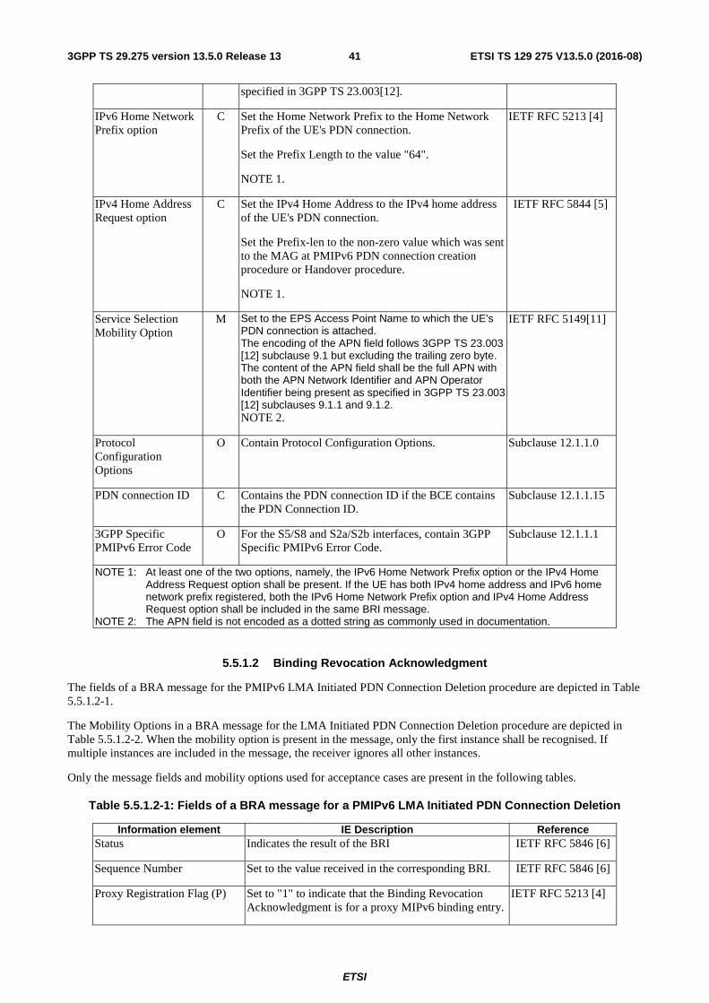
ETSI
ETSI TS 129 275 V13.5.0 (2016-08)413GPP TS 29.275 version 13.5.0 Release 13
specified in 3GPP TS 23.003[12].
IPv6 Home Network Prefix option
C Set the Home Network Prefix to the Home Network Prefix of the UE's PDN connection.
Set the Prefix Length to the value "64".
NOTE 1.
IETF RFC 5213 [4]
IPv4 Home Address Request option
C Set the IPv4 Home Address to the IPv4 home address of the UE's PDN connection.
Set the Prefix-len to the non-zero value which was sent to the MAG at PMIPv6 PDN connection creation procedure or Handover procedure.
NOTE 1.
IETF RFC 5844 [5]
Service Selection Mobility Option
M Set to the EPS Access Point Name to which the UE's PDN connection is attached. The encoding of the APN field follows 3GPP TS 23.003 [12] subclause 9.1 but excluding the trailing zero byte. The content of the APN field shall be the full APN with both the APN Network Identifier and APN Operator Identifier being present as specified in 3GPP TS 23.003 [12] subclauses 9.1.1 and 9.1.2. NOTE 2.
IETF RFC 5149[11]
Protocol Configuration Options
O Contain Protocol Configuration Options. Subclause 12.1.1.0
PDN connection ID C Contains the PDN connection ID if the BCE contains the PDN Connection ID.
Subclause 12.1.1.15
3GPP Specific PMIPv6 Error Code
O For the S5/S8 and S2a/S2b interfaces, contain 3GPP Specific PMIPv6 Error Code.
Subclause 12.1.1.1
NOTE 1: At least one of the two options, namely, the IPv6 Home Network Prefix option or the IPv4 Home Address Request option shall be present. If the UE has both IPv4 home address and IPv6 home network prefix registered, both the IPv6 Home Network Prefix option and IPv4 Home Address Request option shall be included in the same BRI message.
NOTE 2: The APN field is not encoded as a dotted string as commonly used in documentation.
5.5.1.2 Binding Revocation Acknowledgment
The fields of a BRA message for the PMIPv6 LMA Initiated PDN Connection Deletion procedure are depicted in Table 5.5.1.2-1.
The Mobility Options in a BRA message for the LMA Initiated PDN Connection Deletion procedure are depicted in Table 5.5.1.2-2. When the mobility option is present in the message, only the first instance shall be recognised. If multiple instances are included in the message, the receiver ignores all other instances.
Only the message fields and mobility options used for acceptance cases are present in the following tables.
Table 5.5.1.2-1: Fields of a BRA message for a PMIPv6 LMA Initiated PDN Connection Deletion
Information element IE Description Reference Status Indicates the result of the BRI IETF RFC 5846 [6]
Sequence Number Set to the value received in the corresponding BRI. IETF RFC 5846 [6]
Proxy Registration Flag (P) Set to "1" to indicate that the Binding Revocation Acknowledgment is for a proxy MIPv6 binding entry.
IETF RFC 5213 [4]
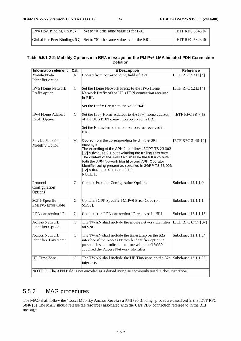
ETSI
ETSI TS 129 275 V13.5.0 (2016-08)423GPP TS 29.275 version 13.5.0 Release 13
IPv4 HoA Binding Only (V) Set to "0"; the same value as for BRI IETF RFC 5846 [6]
Global Per-Peer Bindings (G) Set to "0"; the same value as for the BRI. IETF RFC 5846 [6]
Table 5.5.1.2-2: Mobility Options in a BRA message for the PMIPv6 LMA Initiated PDN Connection Deletion
Information element Cat. IE Description Reference Mobile Node Identifier option
M Copied from corresponding field of BRI. IETF RFC 5213 [4]
IPv6 Home Network Prefix option
C Set the Home Network Prefix to the IPv6 Home Network Prefix of the UE's PDN connection received in BRI.
Set the Prefix Length to the value "64".
IETF RFC 5213 [4]
IPv4 Home Address Reply Option
C Set the IPv4 Home Address to the IPv4 home address of the UE's PDN connection received in BRI.
Set the Prefix-len to the non-zero value received in BRI.
IETF RFC 5844 [5]
Service Selection Mobility Option
M Copied from the corresponding field in the BRI message. The encoding of the APN field follows 3GPP TS 23.003 [12] subclause 9.1 but excluding the trailing zero byte. The content of the APN field shall be the full APN with both the APN Network Identifier and APN Operator Identifier being present as specified in 3GPP TS 23.003 [12] subclauses 9.1.1 and 9.1.2. NOTE 1.
IETF RFC 5149[11]
Protocol Configuration Options
O Contain Protocol Configuration Options Subclause 12.1.1.0
3GPP Specific PMIPv6 Error Code
O Contain 3GPP Specific PMIPv6 Error Code (on S5/S8).
Subclause 12.1.1.1
PDN connection ID C Contains the PDN connection ID received in BRI Subclause 12.1.1.15
Access Network Identifier Option
O The TWAN shall include the access network identifier on S2a.
IETF RFC 6757 [37]
Access Network Identifier Timestamp
O The TWAN shall include the timestamp on the S2a interface if the Access Network Identifier option is present. It shall indicate the time when the TWAN acquired the Access Network Identifier.
Subclause 12.1.1.24
UE Time Zone O The TWAN shall include the UE Timezone on the S2a interface.
Subclause 12.1.1.23
NOTE 1: The APN field is not encoded as a dotted string as commonly used in documentation.
5.5.2 MAG procedures
The MAG shall follow the "Local Mobility Anchor Revokes a PMIPv6 Binding" procedure described in the IETF RFC 5846 [6]. The MAG should release the resources associated with the UE's PDN connection referred to in the BRI message.
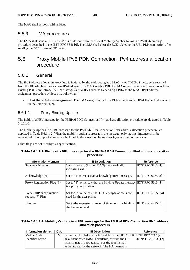
ETSI
ETSI TS 129 275 V13.5.0 (2016-08)433GPP TS 29.275 version 13.5.0 Release 13
The MAG shall respond with a BRA.
5.5.3 LMA procedures
The LMA shall send a BRI to the MAG as described in the "Local Mobility Anchor Revokes a PMIPv6 binding" procedure described in the IETF RFC 5846 [6]. The LMA shall clear the BCE related to the UE's PDN connection after sending the BRI in case of UE detach.
5.6 Proxy Mobile IPv6 PDN Connection IPv4 address allocation procedure
5.6.1 General
The IPv4 address allocation procedure is initiated by the node acting as a MAG when DHCPv4 message is received from the UE which requires a new IPv4 address. The MAG sends a PBU to LMA requesting a new IPv4 address for an existing PDN connection. The LMA assigns a new IPv4 address by sending a PBA to the MAG. IPv4 address assignment procedure achieves the following:
- IPv4 Home Address assignment: The LMA assigns to the UE's PDN connection an IPv4 Home Address valid in the selected PDN.
5.6.1.1 Proxy Binding Update
The fields of a PBU message for the PMIPv6 PDN Connection IPv4 address allocation procedure are depicted in Table 5.6.1.1-1.
The Mobility Options in a PBU message for the PMIPv6 PDN Connection IPv4 address allocation procedure are depicted in Table 5.6.1.1-2. When the mobility option is present in the message, only the first instance shall be recognised. If multiple instances are included in the message, the receiver ignores all other instances.
Other flags are not used by this specification.
Table 5.6.1.1-1: Fields of a PBU message for the PMIPv6 PDN Connection IPv4 address allocation procedure
Information element IE Description Reference Sequence Number Set to a locally (i.e. per MAG) monotonically
increasing value. IETF RFC 5213 [4]
Acknowledge (A) Set to "1" to request an acknowledgement message. IETF RFC 6275 [8]
Proxy Registration Flag (P) Set to "1" to indicate that the Binding Update message is a proxy registration.
IETF RFC 5213 [4]
Force UDP encapsulation request (F) Flag
Set to "0" to indicate that UDP encapsulation is not used for the user plane.
IETF RFC 5555 [34]
Lifetime Set to the requested number of time units the binding shall remain valid.
IETF RFC 6275 [8]
Table 5.6.1.1-2: Mobility Options in a PBU message for the PMIPv6 PDN Connection IPv4 address allocation procedure
Information element Cat. IE Description Reference Mobile Node Identifier option
M Set to the UE NAI that is derived from the UE IMSI if an authenticated IMSI is available, or from the UE IMEI if IMSI is not available or the IMSI is not authenticated by the network. The NAI format is
IETF RFC 5213 [4], 3GPP TS 23.003 [12]
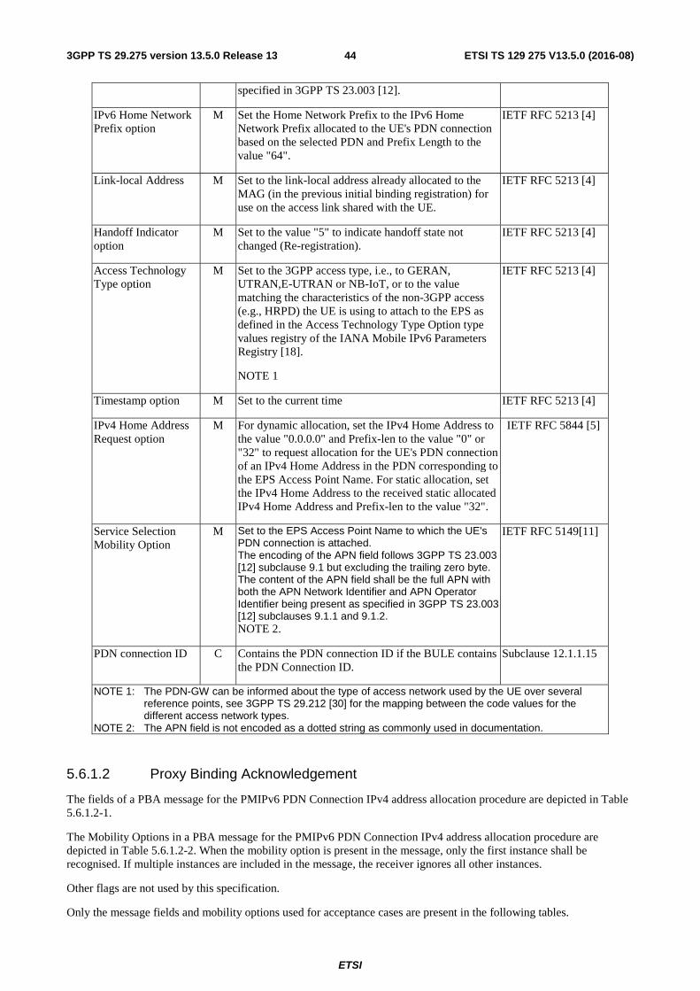
ETSI
ETSI TS 129 275 V13.5.0 (2016-08)443GPP TS 29.275 version 13.5.0 Release 13
specified in 3GPP TS 23.003 [12].
IPv6 Home Network Prefix option
M Set the Home Network Prefix to the IPv6 Home Network Prefix allocated to the UE's PDN connection based on the selected PDN and Prefix Length to the value "64".
IETF RFC 5213 [4]
Link-local Address M Set to the link-local address already allocated to the MAG (in the previous initial binding registration) for use on the access link shared with the UE.
IETF RFC 5213 [4]
Handoff Indicator option
M Set to the value "5" to indicate handoff state not changed (Re-registration).
IETF RFC 5213 [4]
Access Technology Type option
M Set to the 3GPP access type, i.e., to GERAN, UTRAN,E-UTRAN or NB-IoT, or to the value matching the characteristics of the non-3GPP access (e.g., HRPD) the UE is using to attach to the EPS as defined in the Access Technology Type Option type values registry of the IANA Mobile IPv6 Parameters Registry [18].
NOTE 1
IETF RFC 5213 [4]
Timestamp option M Set to the current time IETF RFC 5213 [4]
IPv4 Home Address Request option
M For dynamic allocation, set the IPv4 Home Address to the value "0.0.0.0" and Prefix-len to the value "0" or "32" to request allocation for the UE's PDN connection of an IPv4 Home Address in the PDN corresponding to the EPS Access Point Name. For static allocation, set the IPv4 Home Address to the received static allocated IPv4 Home Address and Prefix-len to the value "32".
IETF RFC 5844 [5]
Service Selection Mobility Option
M Set to the EPS Access Point Name to which the UE's PDN connection is attached. The encoding of the APN field follows 3GPP TS 23.003 [12] subclause 9.1 but excluding the trailing zero byte. The content of the APN field shall be the full APN with both the APN Network Identifier and APN Operator Identifier being present as specified in 3GPP TS 23.003 [12] subclauses 9.1.1 and 9.1.2. NOTE 2.
IETF RFC 5149[11]
PDN connection ID C Contains the PDN connection ID if the BULE contains the PDN Connection ID.
Subclause 12.1.1.15
NOTE 1: The PDN-GW can be informed about the type of access network used by the UE over several reference points, see 3GPP TS 29.212 [30] for the mapping between the code values for the different access network types.
NOTE 2: The APN field is not encoded as a dotted string as commonly used in documentation.
5.6.1.2 Proxy Binding Acknowledgement
The fields of a PBA message for the PMIPv6 PDN Connection IPv4 address allocation procedure are depicted in Table 5.6.1.2-1.
The Mobility Options in a PBA message for the PMIPv6 PDN Connection IPv4 address allocation procedure are depicted in Table 5.6.1.2-2. When the mobility option is present in the message, only the first instance shall be recognised. If multiple instances are included in the message, the receiver ignores all other instances.
Other flags are not used by this specification.
Only the message fields and mobility options used for acceptance cases are present in the following tables.
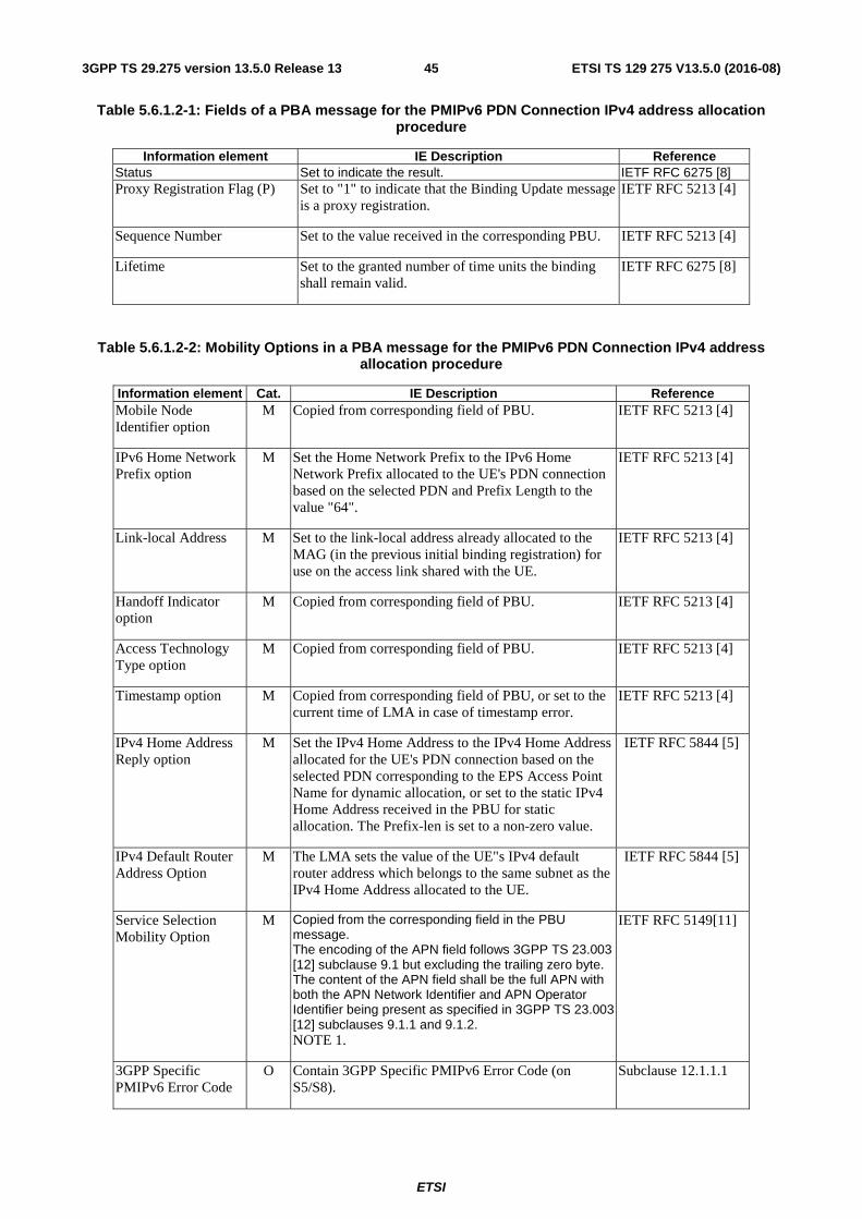
ETSI
ETSI TS 129 275 V13.5.0 (2016-08)453GPP TS 29.275 version 13.5.0 Release 13
Table 5.6.1.2-1: Fields of a PBA message for the PMIPv6 PDN Connection IPv4 address allocation procedure
Information element IE Description Reference Status Set to indicate the result. IETF RFC 6275 [8] Proxy Registration Flag (P) Set to "1" to indicate that the Binding Update message
is a proxy registration. IETF RFC 5213 [4]
Sequence Number Set to the value received in the corresponding PBU. IETF RFC 5213 [4]
Lifetime Set to the granted number of time units the binding shall remain valid.
IETF RFC 6275 [8]
Table 5.6.1.2-2: Mobility Options in a PBA message for the PMIPv6 PDN Connection IPv4 address allocation procedure
Information element Cat. IE Description Reference Mobile Node Identifier option
M Copied from corresponding field of PBU. IETF RFC 5213 [4]
IPv6 Home Network Prefix option
M Set the Home Network Prefix to the IPv6 Home Network Prefix allocated to the UE's PDN connection based on the selected PDN and Prefix Length to the value "64".
IETF RFC 5213 [4]
Link-local Address M Set to the link-local address already allocated to the MAG (in the previous initial binding registration) for use on the access link shared with the UE.
IETF RFC 5213 [4]
Handoff Indicator option
M Copied from corresponding field of PBU. IETF RFC 5213 [4]
Access Technology Type option
M Copied from corresponding field of PBU. IETF RFC 5213 [4]
Timestamp option M Copied from corresponding field of PBU, or set to the current time of LMA in case of timestamp error.
IETF RFC 5213 [4]
IPv4 Home Address Reply option
M Set the IPv4 Home Address to the IPv4 Home Address allocated for the UE's PDN connection based on the selected PDN corresponding to the EPS Access Point Name for dynamic allocation, or set to the static IPv4 Home Address received in the PBU for static allocation. The Prefix-len is set to a non-zero value.
IETF RFC 5844 [5]
IPv4 Default Router Address Option
M The LMA sets the value of the UE"s IPv4 default router address which belongs to the same subnet as the IPv4 Home Address allocated to the UE.
IETF RFC 5844 [5]
Service Selection Mobility Option
M Copied from the corresponding field in the PBU message. The encoding of the APN field follows 3GPP TS 23.003 [12] subclause 9.1 but excluding the trailing zero byte. The content of the APN field shall be the full APN with both the APN Network Identifier and APN Operator Identifier being present as specified in 3GPP TS 23.003 [12] subclauses 9.1.1 and 9.1.2. NOTE 1.
IETF RFC 5149[11]
3GPP Specific PMIPv6 Error Code
O Contain 3GPP Specific PMIPv6 Error Code (on S5/S8).
Subclause 12.1.1.1
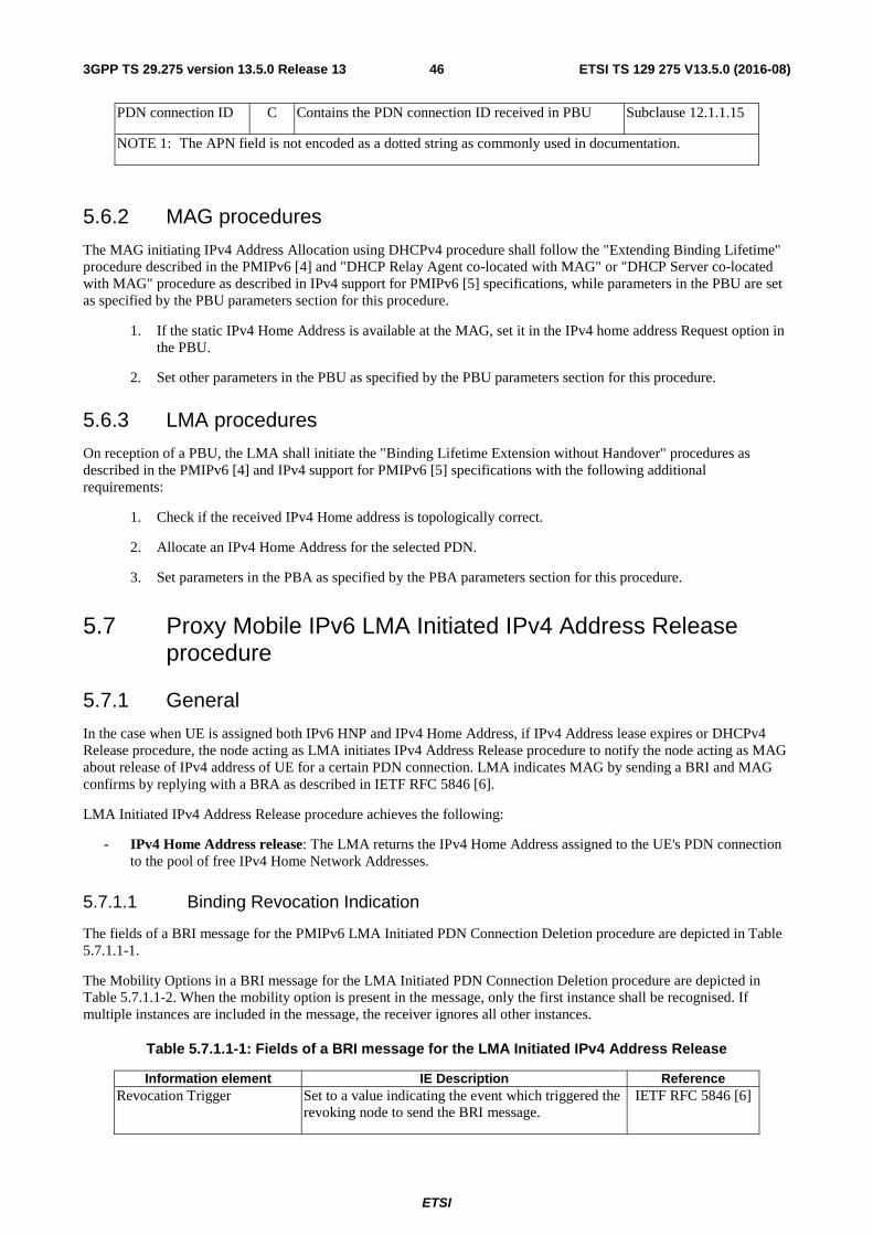
ETSI
ETSI TS 129 275 V13.5.0 (2016-08)463GPP TS 29.275 version 13.5.0 Release 13
PDN connection ID C Contains the PDN connection ID received in PBU Subclause 12.1.1.15
NOTE 1: The APN field is not encoded as a dotted string as commonly used in documentation.
5.6.2 MAG procedures
The MAG initiating IPv4 Address Allocation using DHCPv4 procedure shall follow the "Extending Binding Lifetime" procedure described in the PMIPv6 [4] and "DHCP Relay Agent co-located with MAG" or "DHCP Server co-located with MAG" procedure as described in IPv4 support for PMIPv6 [5] specifications, while parameters in the PBU are set as specified by the PBU parameters section for this procedure.
1. If the static IPv4 Home Address is available at the MAG, set it in the IPv4 home address Request option in the PBU.
2. Set other parameters in the PBU as specified by the PBU parameters section for this procedure.
5.6.3 LMA procedures
On reception of a PBU, the LMA shall initiate the "Binding Lifetime Extension without Handover" procedures as described in the PMIPv6 [4] and IPv4 support for PMIPv6 [5] specifications with the following additional requirements:
1. Check if the received IPv4 Home address is topologically correct.
2. Allocate an IPv4 Home Address for the selected PDN.
3. Set parameters in the PBA as specified by the PBA parameters section for this procedure.
5.7 Proxy Mobile IPv6 LMA Initiated IPv4 Address Release procedure
5.7.1 General
In the case when UE is assigned both IPv6 HNP and IPv4 Home Address, if IPv4 Address lease expires or DHCPv4 Release procedure, the node acting as LMA initiates IPv4 Address Release procedure to notify the node acting as MAG about release of IPv4 address of UE for a certain PDN connection. LMA indicates MAG by sending a BRI and MAG confirms by replying with a BRA as described in IETF RFC 5846 [6].
LMA Initiated IPv4 Address Release procedure achieves the following:
- IPv4 Home Address release: The LMA returns the IPv4 Home Address assigned to the UE's PDN connection to the pool of free IPv4 Home Network Addresses.
5.7.1.1 Binding Revocation Indication
The fields of a BRI message for the PMIPv6 LMA Initiated PDN Connection Deletion procedure are depicted in Table 5.7.1.1-1.
The Mobility Options in a BRI message for the LMA Initiated PDN Connection Deletion procedure are depicted in Table 5.7.1.1-2. When the mobility option is present in the message, only the first instance shall be recognised. If multiple instances are included in the message, the receiver ignores all other instances.
Table 5.7.1.1-1: Fields of a BRI message for the LMA Initiated IPv4 Address Release
Information element IE Description Reference Revocation Trigger Set to a value indicating the event which triggered the
revoking node to send the BRI message. IETF RFC 5846 [6]
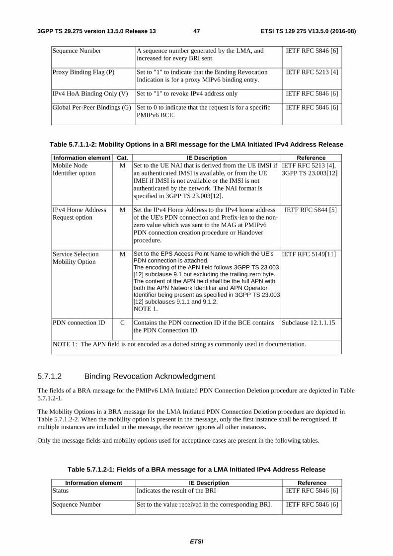
ETSI
ETSI TS 129 275 V13.5.0 (2016-08)473GPP TS 29.275 version 13.5.0 Release 13
Sequence Number A sequence number generated by the LMA, and increased for every BRI sent.
IETF RFC 5846 [6]
Proxy Binding Flag (P) Set to "1" to indicate that the Binding Revocation Indication is for a proxy MIPv6 binding entry.
IETF RFC 5213 [4]
IPv4 HoA Binding Only (V) Set to "1" to revoke IPv4 address only IETF RFC 5846 [6]
Global Per-Peer Bindings (G) Set to 0 to indicate that the request is for a specific PMIPv6 BCE.
IETF RFC 5846 [6]
Table 5.7.1.1-2: Mobility Options in a BRI message for the LMA Initiated IPv4 Address Release
Information element Cat. IE Description Reference Mobile Node Identifier option
M Set to the UE NAI that is derived from the UE IMSI if an authenticated IMSI is available, or from the UE IMEI if IMSI is not available or the IMSI is not authenticated by the network. The NAI format is specified in 3GPP TS 23.003[12].
IETF RFC 5213 [4], 3GPP TS 23.003[12]
IPv4 Home Address Request option
M Set the IPv4 Home Address to the IPv4 home address of the UE's PDN connection and Prefix-len to the non-zero value which was sent to the MAG at PMIPv6 PDN connection creation procedure or Handover procedure.
IETF RFC 5844 [5]
Service Selection Mobility Option
M Set to the EPS Access Point Name to which the UE's PDN connection is attached. The encoding of the APN field follows 3GPP TS 23.003 [12] subclause 9.1 but excluding the trailing zero byte. The content of the APN field shall be the full APN with both the APN Network Identifier and APN Operator Identifier being present as specified in 3GPP TS 23.003 [12] subclauses 9.1.1 and 9.1.2. NOTE 1.
IETF RFC 5149[11]
PDN connection ID C Contains the PDN connection ID if the BCE contains the PDN Connection ID.
Subclause 12.1.1.15
NOTE 1: The APN field is not encoded as a dotted string as commonly used in documentation.
5.7.1.2 Binding Revocation Acknowledgment
The fields of a BRA message for the PMIPv6 LMA Initiated PDN Connection Deletion procedure are depicted in Table 5.7.1.2-1.
The Mobility Options in a BRA message for the LMA Initiated PDN Connection Deletion procedure are depicted in Table 5.7.1.2-2. When the mobility option is present in the message, only the first instance shall be recognised. If multiple instances are included in the message, the receiver ignores all other instances.
Only the message fields and mobility options used for acceptance cases are present in the following tables.
Table 5.7.1.2-1: Fields of a BRA message for a LMA Initiated IPv4 Address Release
Information element IE Description Reference Status Indicates the result of the BRI IETF RFC 5846 [6]
Sequence Number Set to the value received in the corresponding BRI. IETF RFC 5846 [6]
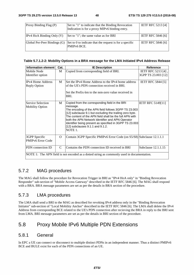
ETSI
ETSI TS 129 275 V13.5.0 (2016-08)483GPP TS 29.275 version 13.5.0 Release 13
Proxy Binding Flag (P) Set to "1" to indicate that the Binding Revocation Indication is for a proxy MIPv6 binding entry.
IETF RFC 5213 [4]
IPv4 HoA Binding Only (V) Set to "1"; the same value as for BRI IETF RFC 5846 [6]
Global Per-Peer Bindings (G) Set to 0 to indicate that the request is for a specific PMIPv6 BCE.
IETF RFC 5846 [6]
Table 5.7.1.2-2: Mobility Options in a BRA message for the LMA Initiated IPv4 Address Release
Information element Cat. IE Description Reference Mobile Node Identifier option
M Copied from corresponding field of BRI. IETF RFC 5213 [4] , 3GPP TS 23.003 [12]
IPv4 Home Address Reply Option
M Set the IPv4 Home Address to the IPv4 home address of the UE's PDN connection received in BRI.
Set the Prefix-len to the non-zero value received in BRI.
IETF RFC 5844 [5]
Service Selection Mobility Option
M Copied from the corresponding field in the BRI message. The encoding of the APN field follows 3GPP TS 23.003 [12] subclause 9.1 but excluding the trailing zero byte. The content of the APN field shall be the full APN with both the APN Network Identifier and APN Operator Identifier being present as specified in 3GPP TS 23.003 [12] subclauses 9.1.1 and 9.1.2. NOTE 1.
IETF RFC 5149[11]
3GPP Specific PMIPv6 Error Code
O Contain 3GPP Specific PMIPv6 Error Code (on S5/S8) Subclause 12.1.1.1
PDN connection ID C Contains the PDN connection ID received in BRI Subclause 12.1.1.15
NOTE 1: The APN field is not encoded as a dotted string as commonly used in documentation.
5.7.2 MAG procedures
The MAG shall follow the procedure for Revocation Trigger in BRI as "IPv4 HoA only" in "Binding Revocation Responder" sub-section of "Mobile Access Gateway" described in the IETF RFC 5846 [6]. The MAG shall respond with a BRA. BRA message parameters are set as per the details in BRA section of the procedure.
5.7.3 LMA procedures
The LMA shall send a BRI to the MAG as described for revoking IPv4 address only in the "Binding Revocation Initiator" sub-section of "Local Mobility Anchor" described in the IETF RFC 5846 [6]. The LMA shall delete the IPv4 Address from corresponding BCE related to the UE's PDN connection after recieving the BRA in reply to the BRI sent from LMA. BRI message parameters are set as per the details in BRI section of the procedure.
5.8 Proxy Mobile IPv6 Multiple PDN Extensions
5.8.1 General
In EPC a UE can connect or disconnect to multiple distinct PDNs in an independent manner. Thus a distinct PMIPv6 BCE and BULE exist for each of the PDN connections of an UE.
ETSI
ETSI TS 129 275 V13.5.0 (2016-08)493GPP TS 29.275 version 13.5.0 Release 13
Supporting multiple PDN connections to the same APN function is optional for MAG and LMA. A MAG which supports the multiple PDN connections to the same APN function shall include PDN connection ID in the PBU message at initial attach/handover procedure. If the LMA supports the multiple PDN connections to the same APN function, it shall include the received PDN connection ID in the PBA message. If the LMA does not support the multiple PDN connections to the same APN function, it shall ignore the received PDN connection ID and shall not include the PDN connection ID in the PBA message. If the received PBA message does not contain a PDN connection ID, the MAG shall not send any PBU message for additional PDN connectivity request to the same APN for the same UE.
5.8.2 Extensions to PMIPv6 Data Structure
There shall be a unique BCE and BULE for each PDN connection. Each PDN connection can be uniquely identified by MN ID, an APN, and optionally a PDN connection ID in the BCE and BULE.
To support Multiple PDNs the MAG and LMA maintains extended data structure compared to the standard PMIPv6 as defined in IETF RFC 5213 [4]. Since multiple PDN connections of a UE can be distinguised based on an APN, both the BCE on the LMA and the BULE on the MAG need to be extended with the following additional field:
- APN of a UE's PDN connection.
Moreover, to support multiple PDN connections to the same APN function, the MAG and LMA shall maintain extended data structure compared to the PMIPv6 data structure described above. This extension is only applicable if multiple PDN connections to the same APN function is supported by both MAG and LMA.
Since the multiple PDN connections with the same APN of a UE shall be distinguished based on MN ID, an APN, and a PDN connection ID, both the BCE on the LMA and the BULE on the MAG need to be extended with the following additional field:
- PDN connection ID of a UE's PDN connection. The PDN connection ID is provided by the MAG to the LMA at PDN Connection Creation procedure or Handover procedure. For S2a/S2b interface, the MAG generates the PDN connection ID which shall be unique per MN-ID per APN. How the MAG generates the PDN Connection ID for the S2a and S2b reference points is out of scope of 3GPP. For S5/S8 interface, the MAG uses the EPS bearer identity of the default bearer as PDN connection ID.
5.8.3 Extensions to PMIPv6 BULE and BCE Lookups
5.8.3.1 General
To support Multiple PDNs the MAG and LMA perform extended lookups on the extended data structure compared to the standard PMIPv6 as defined in IETF RFC 5213 [4].
In standard PMIPv6 as defined in IETF RFC 5213 [4], a PMIPv6 BCE/BULE is looked up based on the Mobile Node Identifier (MN-Id), the access technology types (ATT) and if it exist the MN's link-layer identifier (MN-LL-Id).
In EPC the MN-LL-Id is not used and the EPC support handover between different interfaces for handover between non-3GPP and 3GPP accesses.
Distinct PMIPv6 BCE and BULE exist for each of the PDN connections of an UE.
The feature of having multiple PDN connections to the same APN is only supported if both MAG and LMA support it.
5.8.3.2 Extensions to PMIPv6 BCE Lookups
If the multiple PDN connections to the same APN feature is not supported, all PDN connections of a UE can be distinguished based on an APN and there is a one-to-one mapping between a PMIPv6 BCE, a PDN connection, and the (MN-Id, APN) tuple. An UE PDN connection can be uniquely identified by a (MN-Id, APN) tuple, the BCE is accordingly looked up on a per (MN-Id, APN) tuple basis.
If the multiple PDN connections to the same APN feature is supported, the LMA shall store the received PDN connection ID in the BCE. There is a one-to-one mapping between a PMIPv6 BCE, a PDN connection, and the (MN-Id, APN, PDN connection ID) tuple. Thus, an UE PDN connection can be uniquely identified by a (MN-Id, APN, PDN connection ID) tuple. The BCE is accordingly looked up as follows:
ETSI
ETSI TS 129 275 V13.5.0 (2016-08)503GPP TS 29.275 version 13.5.0 Release 13
- If a PDN connection ID is received in the request message, the PMIPv6 BCE is looked up based on the (MN-Id, APN, PDN connection ID) tuple. If no existing binding is found based on the (MN-Id, APN, PDN connection ID) tuple, the LMA shall re-perform the PMIPv6 BCE lookup based on a per (MN-Id, APN) tuple.
- If a PDN connection ID is not received in the request message, the PMIPv6 BCE lookup is based on a per (MN-Id, APN) tuple.
5.8.3.3 Extensions to PMIPv6 BULE Lookups
If the multiple PDN connections to the same APN feature is not supported, an UE PDN connection can be uniquely identified by a (MN-Id, APN) tuple. In this case the BULE is accordingly looked up on a per (MN-Id, APN) tuple basis.
If the multiple PDN connections to the same APN feature is supported, the MAG shall generate a PDN connection ID per PDN connection and store it in the BULE. Thus, there is a one-to-one mapping between a PMIPv6 BULE, a PDN connection, and the (MN-Id, APN, PDN connection ID) tuple. An UE PDN connection can be uniquely identified by a per (MN-Id, APN, PDN connection ID) tuple. The BULE is accordingly looked up on a per (MN-Id, APN, PDN connection ID) tuple basis.
5.8.4 Extensions to PMIPv6 Procedure
5.8.4.1 General
The processing rules on the received PMIPv6 message are specified in IETF RFC 5213 [4] and IETF RFC 5844 [5]. This subclause specifies the additional PMIPv6 procedures.
5.8.4.2 MAG procedure
If the PMIPv6 PBU retransmission is triggered, a PMIPv6 PBU message with identical mobility options, except the value of the Timestamp option is new, shall be sent.
5.8.4.3 LMA procedure
If before responding to a received PMIPv6 PBU message, a new PMIPv6 PBU message with the same MN-ID, APN (and PDN connection ID) mobility options is received, then the LMA may respond to one or all of the received PMIPv6 PBU messages.
If the LMA receives a PMIPv6 PBU message with HI = 1 from the same MAG and an existing BCE with the same MN-ID, APN (and PDN connection ID) is found, the LMA may refresh the BCE or release the old BCE and create a new one based on the received PBU message.
5.9 Serving GW Procedure at Chaining Case
5.9.1 General
Chained S2a/S2b with GTP-based S8 is not supported in this release.
Chained S2a/S2b with PMIP-based S8 is used when VPLMN has business relationship with Non-3GPP Networks and Serving GW in VPLMN supporting a LMA function as local non-3GPP Anchor.
5.9.2 Signalling procedures
When either of the S2a or S2b interfaces is chained with a PMIP-based S8 interface, the Serving GW acts as the signaling endpoint for each interface. On the S2a or S2b interface, the Serving GW acts as an LMA. On the chained PMIP-based S8 interface, the Serving GW acts as MAG. When a procedure is initiated by its peer on a given interface for a given PDN connection, the Serving GW shall trigger an equivalent procedure over the chained interface for the designated PDN connection. The procedure initiated by its peer cannot be completed before the completion of the equivalent procedure initiated over the chained interface.
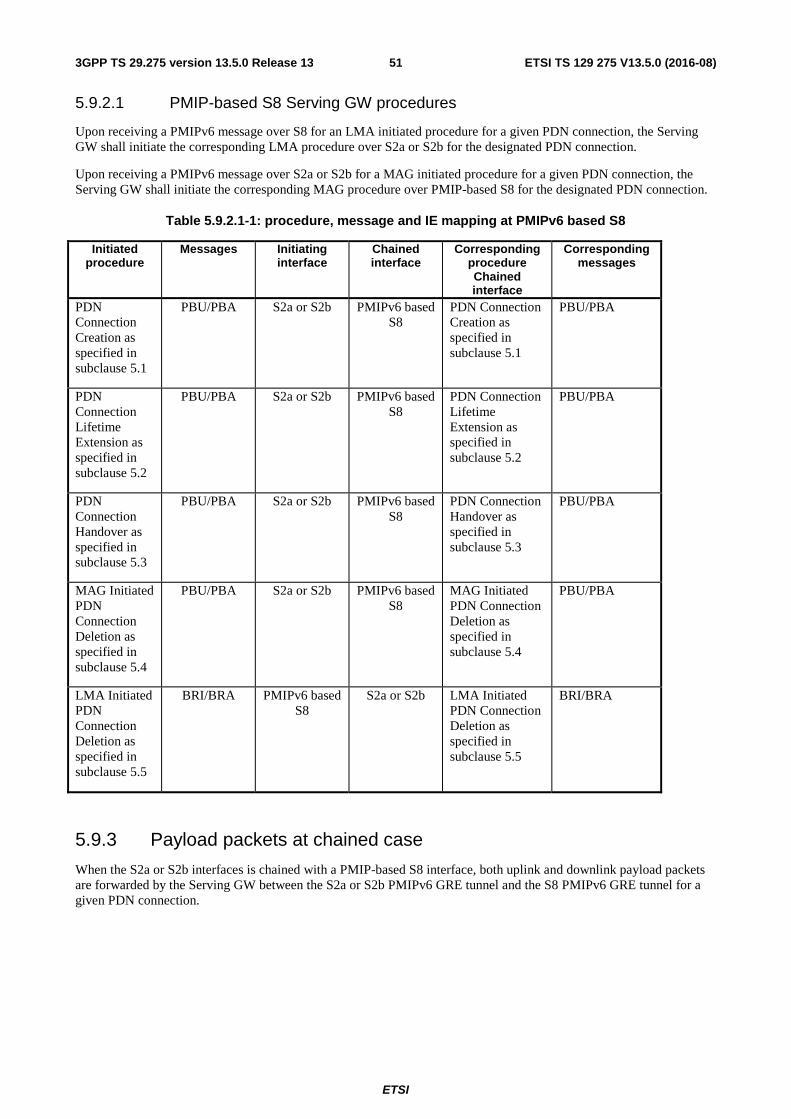
ETSI
ETSI TS 129 275 V13.5.0 (2016-08)513GPP TS 29.275 version 13.5.0 Release 13
5.9.2.1 PMIP-based S8 Serving GW procedures
Upon receiving a PMIPv6 message over S8 for an LMA initiated procedure for a given PDN connection, the Serving GW shall initiate the corresponding LMA procedure over S2a or S2b for the designated PDN connection.
Upon receiving a PMIPv6 message over S2a or S2b for a MAG initiated procedure for a given PDN connection, the Serving GW shall initiate the corresponding MAG procedure over PMIP-based S8 for the designated PDN connection.
Table 5.9.2.1-1: procedure, message and IE mapping at PMIPv6 based S8
Initiated procedure
Messages Initiating interface
Chained interface
Corresponding procedure Chained interface
Corresponding messages
PDN Connection Creation as specified in subclause 5.1
PBU/PBA S2a or S2b PMIPv6 based S8
PDN Connection Creation as specified in subclause 5.1
PBU/PBA
PDN Connection Lifetime Extension as specified in subclause 5.2
PBU/PBA S2a or S2b PMIPv6 based S8
PDN Connection Lifetime Extension as specified in subclause 5.2
PBU/PBA
PDN Connection Handover as specified in subclause 5.3
PBU/PBA S2a or S2b PMIPv6 based S8
PDN Connection Handover as specified in subclause 5.3
PBU/PBA
MAG Initiated PDN Connection Deletion as specified in subclause 5.4
PBU/PBA S2a or S2b PMIPv6 based S8
MAG Initiated PDN Connection Deletion as specified in subclause 5.4
PBU/PBA
LMA Initiated PDN Connection Deletion as specified in subclause 5.5
BRI/BRA PMIPv6 based S8
S2a or S2b LMA Initiated PDN Connection Deletion as specified in subclause 5.5
BRI/BRA
5.9.3 Payload packets at chained case
When the S2a or S2b interfaces is chained with a PMIP-based S8 interface, both uplink and downlink payload packets are forwarded by the Serving GW between the S2a or S2b PMIPv6 GRE tunnel and the S8 PMIPv6 GRE tunnel for a given PDN connection.
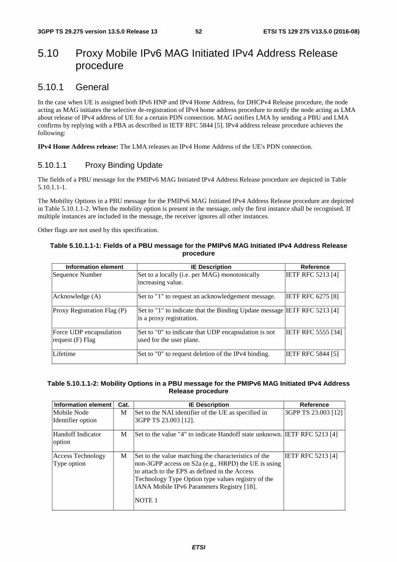
ETSI
ETSI TS 129 275 V13.5.0 (2016-08)523GPP TS 29.275 version 13.5.0 Release 13
5.10 Proxy Mobile IPv6 MAG Initiated IPv4 Address Release procedure
5.10.1 General
In the case when UE is assigned both IPv6 HNP and IPv4 Home Address, for DHCPv4 Release procedure, the node acting as MAG initiates the selective de-registration of IPv4 home address procedure to notify the node acting as LMA about release of IPv4 address of UE for a certain PDN connection. MAG notifies LMA by sending a PBU and LMA confirms by replying with a PBA as described in IETF RFC 5844 [5]. IPv4 address release procedure achieves the following:
IPv4 Home Address release: The LMA releases an IPv4 Home Address of the UE's PDN connection.
5.10.1.1 Proxy Binding Update
The fields of a PBU message for the PMIPv6 MAG Initiated IPv4 Address Release procedure are depicted in Table 5.10.1.1-1.
The Mobility Options in a PBU message for the PMIPv6 MAG Initiated IPv4 Address Release procedure are depicted in Table 5.10.1.1-2. When the mobility option is present in the message, only the first instance shall be recognised. If multiple instances are included in the message, the receiver ignores all other instances.
Other flags are not used by this specification.
Table 5.10.1.1-1: Fields of a PBU message for the PMIPv6 MAG Initiated IPv4 Address Release procedure
Information element IE Description Reference Sequence Number Set to a locally (i.e. per MAG) monotonically
increasing value. IETF RFC 5213 [4]
Acknowledge (A) Set to "1" to request an acknowledgement message. IETF RFC 6275 [8]
Proxy Registration Flag (P) Set to "1" to indicate that the Binding Update message is a proxy registration.
IETF RFC 5213 [4]
Force UDP encapsulation request (F) Flag
Set to "0" to indicate that UDP encapsulation is not used for the user plane.
IETF RFC 5555 [34]
Lifetime Set to "0" to request deletion of the IPv4 binding. IETF RFC 5844 [5]
Table 5.10.1.1-2: Mobility Options in a PBU message for the PMIPv6 MAG Initiated IPv4 Address Release procedure
Information element Cat. IE Description Reference Mobile Node Identifier option
M Set to the NAI identifier of the UE as specified in 3GPP TS 23.003 [12].
3GPP TS 23.003 [12]
Handoff Indicator option
M Set to the value "4" to indicate Handoff state unknown. IETF RFC 5213 [4]
Access Technology Type option
M Set to the value matching the characteristics of the non-3GPP access on S2a (e.g., HRPD) the UE is using to attach to the EPS as defined in the Access Technology Type Option type values registry of the IANA Mobile IPv6 Parameters Registry [18].
NOTE 1
IETF RFC 5213 [4]
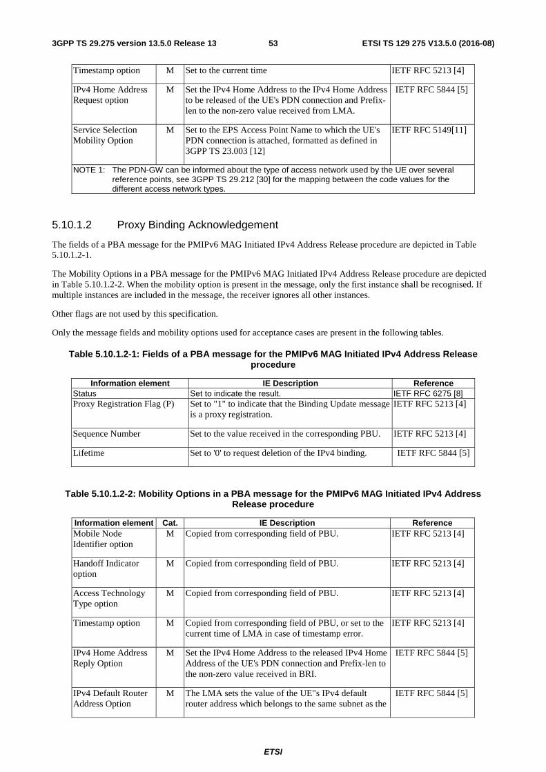
ETSI
ETSI TS 129 275 V13.5.0 (2016-08)533GPP TS 29.275 version 13.5.0 Release 13
Timestamp option M Set to the current time IETF RFC 5213 [4]
IPv4 Home Address Request option
M Set the IPv4 Home Address to the IPv4 Home Address to be released of the UE's PDN connection and Prefix-len to the non-zero value received from LMA.
IETF RFC 5844 [5]
Service Selection Mobility Option
M Set to the EPS Access Point Name to which the UE's PDN connection is attached, formatted as defined in 3GPP TS 23.003 [12]
IETF RFC 5149[11]
NOTE 1: The PDN-GW can be informed about the type of access network used by the UE over several reference points, see 3GPP TS 29.212 [30] for the mapping between the code values for the different access network types.
5.10.1.2 Proxy Binding Acknowledgement
The fields of a PBA message for the PMIPv6 MAG Initiated IPv4 Address Release procedure are depicted in Table 5.10.1.2-1.
The Mobility Options in a PBA message for the PMIPv6 MAG Initiated IPv4 Address Release procedure are depicted in Table 5.10.1.2-2. When the mobility option is present in the message, only the first instance shall be recognised. If multiple instances are included in the message, the receiver ignores all other instances.
Other flags are not used by this specification.
Only the message fields and mobility options used for acceptance cases are present in the following tables.
Table 5.10.1.2-1: Fields of a PBA message for the PMIPv6 MAG Initiated IPv4 Address Release procedure
Information element IE Description Reference Status Set to indicate the result. IETF RFC 6275 [8] Proxy Registration Flag (P) Set to "1" to indicate that the Binding Update message
is a proxy registration. IETF RFC 5213 [4]
Sequence Number Set to the value received in the corresponding PBU. IETF RFC 5213 [4]
Lifetime Set to '0' to request deletion of the IPv4 binding. IETF RFC 5844 [5]
Table 5.10.1.2-2: Mobility Options in a PBA message for the PMIPv6 MAG Initiated IPv4 Address Release procedure
Information element Cat. IE Description Reference Mobile Node Identifier option
M Copied from corresponding field of PBU. IETF RFC 5213 [4]
Handoff Indicator option
M Copied from corresponding field of PBU. IETF RFC 5213 [4]
Access Technology Type option
M Copied from corresponding field of PBU. IETF RFC 5213 [4]
Timestamp option M Copied from corresponding field of PBU, or set to the current time of LMA in case of timestamp error.
IETF RFC 5213 [4]
IPv4 Home Address Reply Option
M Set the IPv4 Home Address to the released IPv4 Home Address of the UE's PDN connection and Prefix-len to the non-zero value received in BRI.
IETF RFC 5844 [5]
IPv4 Default Router Address Option
M The LMA sets the value of the UE"s IPv4 default router address which belongs to the same subnet as the
IETF RFC 5844 [5]
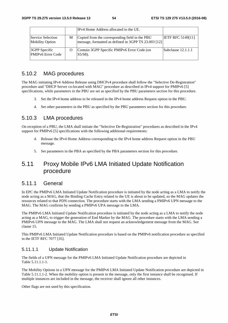
ETSI
ETSI TS 129 275 V13.5.0 (2016-08)543GPP TS 29.275 version 13.5.0 Release 13
IPv4 Home Address allocated to the UE.
Service Selection Mobility Option
M Copied from the corresponding field in the PBU message, formatted as defined in 3GPP TS 23.003 [12]
IETF RFC 5149[11]
3GPP Specific PMIPv6 Error Code
O Contain 3GPP Specific PMIPv6 Error Code (on S5/S8).
Subclause 12.1.1.1
5.10.2 MAG procedures
The MAG initiating IPv4 Address Release using DHCPv4 procedure shall follow the "Selective De-Registration" procedure and "DHCP Server co-located with MAG" procedure as described in IPv4 support for PMIPv6 [5] specifications, while parameters in the PBU are set as specified by the PBU parameters section for this procedure.
3. Set the IPv4 home address to be released in the IPv4 home address Request option in the PBU.
4. Set other parameters in the PBU as specified by the PBU parameters section for this procedure.
5.10.3 LMA procedures
On reception of a PBU, the LMA shall initiate the "Selective De-Registration" procedures as described in the IPv4 support for PMIPv6 [5] specifications with the following additional requirements:
4. Release the IPv4 Home Address corresponding to the IPv4 home address Request option in the PBU message.
5. Set parameters in the PBA as specified by the PBA parameters section for this procedure.
5.11 Proxy Mobile IPv6 LMA Initiated Update Notification procedure
5.11.1 General
In EPC the PMIPv6 LMA Initiated Update Notification procedure is initiated by the node acting as a LMA to notify the node acting as a MAG, that the Binding Cache Entry related to the UE is about to be updated, so the MAG updates the resources related to that PDN connection. The procedure starts with the LMA sending a PMIPv6 UPN message to the MAG. The MAG confirms by sending a PMIPv6 UPA message to the LMA.
The PMIPv6 LMA Initiated Update Notification procedure is initiated by the node acting as a LMA to notify the node acting as a MAG, to trigger the generation of End Marker by the MAG. The procedure starts with the LMA sending a PMIPv6 UPN message to the MAG. The LMA shall not request an acknowledgement message from the MAG. See clause 15.
This PMIPv6 LMA Initiated Update Notification procedure is based on the PMIPv6 notification procedure as specified in the IETF RFC 7077 [35].
5.11.1.1 Update Notification
The fields of a UPN message for the PMIPv6 LMA Initiated Update Notification procedure are depicted in Table 5.11.1.1-1.
The Mobility Options in a UPN message for the PMIPv6 LMA Initiated Update Notification procedure are depicted in Table 5.11.1.1-2. When the mobility option is present in the message, only the first instance shall be recognised. If multiple instances are included in the message, the receiver shall ignore all other instances.
Other flags are not used by this specification.
ETSI
ETSI TS 129 275 V13.5.0 (2016-08)553GPP TS 29.275 version 13.5.0 Release 13
Table 5.11.1.1-1: Fields of a UPN message for the PMIPv6 LMA Initiate Update Notification procedure
Information element Description Reference Sequence Number Set to a locally (i.e. per LMA) monotonically
increasing value. IETF RFC 5213 [4]
Notification Reason Set to the corresponding notification reason IETF RFC 7077 [35]
Acknowledge (A) Set to "1" to request an acknowledgement message.
Set to "0" not to request an acknowledgement message.
IETF RFC 7077 [35]
Table 5.11.1.1-2: Mobility Options in a UPN message for the PMIPv6 LMA Initiated Update Notification procedure
Information element Cat. IE Description Reference Mobile Node Identifier option
M Set to the NAI identifier of the UE as specified in 3GPP TS 23.003 [12].
3GPP TS 23.003 [12]
Service Selection Mobility Option
O This IE shall be set to the EPS Access Point Name to which the UE's PDN connection is attached.
IETF RFC 5149 [11]
PDN connection ID O This IE shall contain the PDN connection ID if the BCE contains the PDN Connection ID.
Subclause 12.1.1.15
MME/SGSN Identifier
O Contains the MME/S4-SGSN identifier Subclause 12.1.1.20
Protocol Configuration Option
O Contains Protocol Configuration Options. Subclause 12.1.1.0
End Marker Notification
O Contains the End Marker Notification (on S5/S8). Subclause 12.1.1.21
PDN GW IP Address O Contains PDN GW IP address for control plane used by the PDN connection.
Subclause 12.1.1.4
GRE key option O Contains the uplink GRE key for control plane used by the PDN connection.
IETF RFC 5845 [7]
Additional Protocol Configuration Option
O Contains Additional Protocol Configuration Options. Subclause 12.1.1.19
5.11.1.2 Update Notification Acknowledgement
The fields of a UPA message for the PMIPv6 LMA Initiated Update procedure are depicted in Table 5.11.1.2-1.
The Mobility Options in a UPA message for the PMIPv6 LMA Initiated Update procedure are depicted in Table 5.11.1.2-2. When the mobility option is present in the message, only the first instance shall be recognised. If multiple instances are included in the message, the receiver shall ignore all other instances.
Other flags are not used by this specification.
Only the message fields and mobility options used for acceptance cases are present in the following tables.
Table 5.11.1.2-1: Fields of a UPA message for the PMIPv6 LMA Initiated Update Notification procedure
Information element Description Reference Sequence Number Set to the value received in the corresponding UPN. IETF RFC 5213 [4]
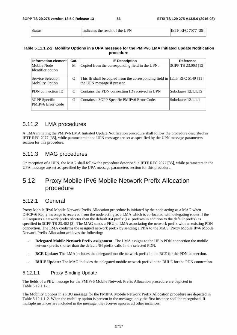
ETSI
ETSI TS 129 275 V13.5.0 (2016-08)563GPP TS 29.275 version 13.5.0 Release 13
Status Indicates the result of the UPN IETF RFC 7077 [35]
Table 5.11.1.2-2: Mobility Options in a UPA message for the PMIPv6 LMA Initiated Update Notification procedure
Information element Cat. IE Description Reference Mobile Node Identifier option
M Copied from the corresponding field in the UPN. 3GPP TS 23.003 [12]
Service Selection Mobility Option
O This IE shall be copied from the corresponding field in the UPN message if present.
IETF RFC 5149 [11]
PDN connection ID C Contains the PDN connection ID received in UPN Subclause 12.1.1.15
3GPP Specific PMIPv6 Error Code
O Contains a 3GPP Specific PMIPv6 Error Code. Subclause 12.1.1.1
5.11.2 LMA procedures
A LMA initiating the PMIPv6 LMA Initiated Update Notification procedure shall follow the procedure described in IETF RFC 7077 [35], while parameters in the UPN message are set as specified by the UPN message parameters section for this procedure.
5.11.3 MAG procedures
On reception of a UPN, the MAG shall follow the procedure described in IETF RFC 7077 [35], while parameters in the UPA message are set as specified by the UPA message parameters section for this procedure.
5.12 Proxy Mobile IPv6 Mobile Network Prefix Allocation procedure
5.12.1 General
Proxy Mobile IPv6 Mobile Network Prefix Allocation procedure is initiated by the node acting as a MAG when DHCPv6 Reply message is received from the node acting as a LMA which is co-located with delegating router if the UE requests a network prefix shorter than the default /64 prefix (i.e. prefixes in addition to the default prefix) as specified in 3GPP TS 23.402 [3]. The MAG sends a PBU to LMA associating the network prefix with an existing PDN connection. The LMA confirms the assigned network prefix by sending a PBA to the MAG. Proxy Mobile IPv6 Mobile Network Prefix Allocation achieves the following:
- Delegated Mobile Network Prefix assignment: The LMA assigns to the UE"s PDN connection the mobile network prefix shorter than the default /64 prefix valid in the selected PDN.
- BCE Update: The LMA includes the delegated mobile network prefix in the BCE for the PDN connection.
- BULE Update: The MAG includes the delegated mobile network prefix in the BULE for the PDN connection.
5.12.1.1 Proxy Binding Update
The fields of a PBU message for the PMIPv6 Mobile Network Prefix Allocation procedure are depicted in Table 5.12.1.1-1.
The Mobility Options in a PBU message for the PMIPv6 Mobile Network Prefix Allocation procedure are depicted in Table 5.12.1.1-2. When the mobility option is present in the message, only the first instance shall be recognised. If multiple instances are included in the message, the receiver ignores all other instances.
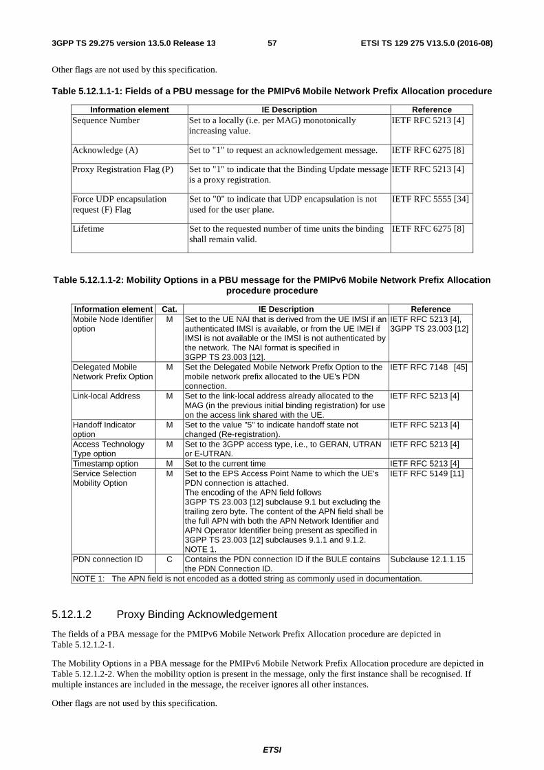
ETSI
ETSI TS 129 275 V13.5.0 (2016-08)573GPP TS 29.275 version 13.5.0 Release 13
Other flags are not used by this specification.
Table 5.12.1.1-1: Fields of a PBU message for the PMIPv6 Mobile Network Prefix Allocation procedure
Information element IE Description Reference Sequence Number Set to a locally (i.e. per MAG) monotonically
increasing value. IETF RFC 5213 [4]
Acknowledge (A) Set to "1" to request an acknowledgement message. IETF RFC 6275 [8]
Proxy Registration Flag (P) Set to "1" to indicate that the Binding Update message is a proxy registration.
IETF RFC 5213 [4]
Force UDP encapsulation request (F) Flag
Set to "0" to indicate that UDP encapsulation is not used for the user plane.
IETF RFC 5555 [34]
Lifetime Set to the requested number of time units the binding shall remain valid.
IETF RFC 6275 [8]
Table 5.12.1.1-2: Mobility Options in a PBU message for the PMIPv6 Mobile Network Prefix Allocation procedure procedure
Information element Cat. IE Description Reference Mobile Node Identifier option
M Set to the UE NAI that is derived from the UE IMSI if an authenticated IMSI is available, or from the UE IMEI if IMSI is not available or the IMSI is not authenticated by the network. The NAI format is specified in 3GPP TS 23.003 [12].
IETF RFC 5213 [4], 3GPP TS 23.003 [12]
Delegated Mobile Network Prefix Option
M Set the Delegated Mobile Network Prefix Option to the mobile network prefix allocated to the UE's PDN connection.
IETF RFC 7148 [45]
Link-local Address M Set to the link-local address already allocated to the MAG (in the previous initial binding registration) for use on the access link shared with the UE.
IETF RFC 5213 [4]
Handoff Indicator option
M Set to the value "5" to indicate handoff state not changed (Re-registration).
IETF RFC 5213 [4]
Access Technology Type option
M Set to the 3GPP access type, i.e., to GERAN, UTRAN or E-UTRAN.
IETF RFC 5213 [4]
Timestamp option M Set to the current time IETF RFC 5213 [4] Service Selection Mobility Option
M Set to the EPS Access Point Name to which the UE's PDN connection is attached. The encoding of the APN field follows 3GPP TS 23.003 [12] subclause 9.1 but excluding the trailing zero byte. The content of the APN field shall be the full APN with both the APN Network Identifier and APN Operator Identifier being present as specified in 3GPP TS 23.003 [12] subclauses 9.1.1 and 9.1.2. NOTE 1.
IETF RFC 5149 [11]
PDN connection ID C Contains the PDN connection ID if the BULE contains the PDN Connection ID.
Subclause 12.1.1.15
NOTE 1: The APN field is not encoded as a dotted string as commonly used in documentation.
5.12.1.2 Proxy Binding Acknowledgement
The fields of a PBA message for the PMIPv6 Mobile Network Prefix Allocation procedure are depicted in Table 5.12.1.2-1.
The Mobility Options in a PBA message for the PMIPv6 Mobile Network Prefix Allocation procedure are depicted in Table 5.12.1.2-2. When the mobility option is present in the message, only the first instance shall be recognised. If multiple instances are included in the message, the receiver ignores all other instances.
Other flags are not used by this specification.
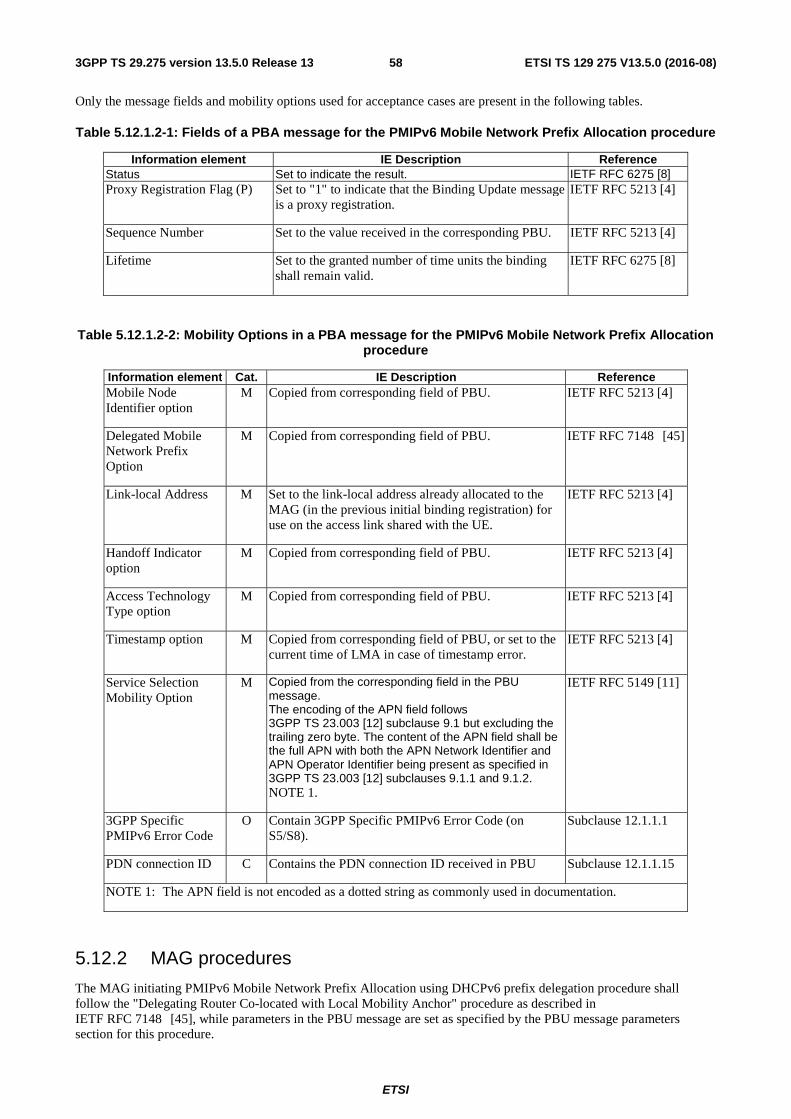
ETSI
ETSI TS 129 275 V13.5.0 (2016-08)583GPP TS 29.275 version 13.5.0 Release 13
Only the message fields and mobility options used for acceptance cases are present in the following tables.
Table 5.12.1.2-1: Fields of a PBA message for the PMIPv6 Mobile Network Prefix Allocation procedure
Information element IE Description Reference Status Set to indicate the result. IETF RFC 6275 [8] Proxy Registration Flag (P) Set to "1" to indicate that the Binding Update message
is a proxy registration. IETF RFC 5213 [4]
Sequence Number Set to the value received in the corresponding PBU. IETF RFC 5213 [4]
Lifetime Set to the granted number of time units the binding shall remain valid.
IETF RFC 6275 [8]
Table 5.12.1.2-2: Mobility Options in a PBA message for the PMIPv6 Mobile Network Prefix Allocation procedure
Information element Cat. IE Description Reference Mobile Node Identifier option
M Copied from corresponding field of PBU. IETF RFC 5213 [4]
Delegated Mobile Network Prefix Option
M Copied from corresponding field of PBU. IETF RFC 7148 [45]
Link-local Address M Set to the link-local address already allocated to the MAG (in the previous initial binding registration) for use on the access link shared with the UE.
IETF RFC 5213 [4]
Handoff Indicator option
M Copied from corresponding field of PBU. IETF RFC 5213 [4]
Access Technology Type option
M Copied from corresponding field of PBU. IETF RFC 5213 [4]
Timestamp option M Copied from corresponding field of PBU, or set to the current time of LMA in case of timestamp error.
IETF RFC 5213 [4]
Service Selection Mobility Option
M Copied from the corresponding field in the PBU message. The encoding of the APN field follows 3GPP TS 23.003 [12] subclause 9.1 but excluding the trailing zero byte. The content of the APN field shall be the full APN with both the APN Network Identifier and APN Operator Identifier being present as specified in 3GPP TS 23.003 [12] subclauses 9.1.1 and 9.1.2. NOTE 1.
IETF RFC 5149 [11]
3GPP Specific PMIPv6 Error Code
O Contain 3GPP Specific PMIPv6 Error Code (on S5/S8).
Subclause 12.1.1.1
PDN connection ID C Contains the PDN connection ID received in PBU Subclause 12.1.1.15
NOTE 1: The APN field is not encoded as a dotted string as commonly used in documentation.
5.12.2 MAG procedures
The MAG initiating PMIPv6 Mobile Network Prefix Allocation using DHCPv6 prefix delegation procedure shall follow the "Delegating Router Co-located with Local Mobility Anchor" procedure as described in IETF RFC 7148 [45], while parameters in the PBU message are set as specified by the PBU message parameters section for this procedure.

ETSI
ETSI TS 129 275 V13.5.0 (2016-08)593GPP TS 29.275 version 13.5.0 Release 13
5.12.3 LMA procedures
On reception of a PBU, the LMA shall initiate the " Delegating Router Co-located with Local Mobility Anchor " procedures as described described in IETF RFC 7148 [45], while parameters in the PBA message are set as specified by the PBA message parameters section for this procedure.
ETSI
ETSI TS 129 275 V13.5.0 (2016-08)603GPP TS 29.275 version 13.5.0 Release 13
6 Tunnel Management procedures
6.1 General The Mobile Anchor Gateway (MAG) and the Local Mobility Anchor (LMA) establish and maintain a bi-directional tunnel for each PDN connection, which is used for routing the UE"s PDN connection user-plane traffic between the MAG and the LMA. This tunnel is based on GRE encapsulation as specified in IETF RFC 2890 [21] (see also IETF RFC 2784 [20]) and is established as a result of exchanging the Proxy Binding Update (PBU) and the Proxy Binding Acknowledgment (PBA) messages between the MAG and LMA. The PBU and PBA messages establish unique Binding Cache Entry (BCE) and Binding Update List Entry (BULE) entries for each PDN connection at the LMA and the MAG respectively. The tunnel end points are:
- the Proxy-CoA at the MAG and LMAA or LMA User Plane Address (if an alternate address is used for user plane) at the LMA with GRE encapsulation (for IPv6 transport network); or
- the IPv4-Proxy-CoA at the MAG and IPv4-LMAA or LMA User Plane Address (if an alternate address is used for user plane) at the LMA with GRE encapsulation (for IPv4 transport network), as described in IETF RFC 5845 [7].
GRE encapsulation shall always be used; the GRE tunneling negotiation described in IETF RFC 5845 [7] is not applicable and the GRE Key Identifier Option shall always be present in the PBU messages for PMIPv6 PDN Connection Creation and binding registration after handover.
The LMA may assign an alternate LMAA or IPv4-LMAA during the setup of the PDN connection, if this option is supported by both MAG and LMA.
Tear down of GRE tunnels and cleanup of state is done explicitly by MAG Initiated PDN Connection Deletion or LMA Initiated PDN Connection Deletion; additionally, the tunnel is torn down when the binding lifetime expires as described in IETF RFC 5213 [4].
A PMIPv6 node (MAG or LMA), which uses the control plane A protocol stack (see subclause 4.2) shall send signalling messages specified in Section 5 with IPv4-UDP encapsulation in IPv4 transport network as specified in IETF RFC 5844 [5].
A PMIPv6 node (MAG or LMA), which uses the control plane B protocol stack (see subclause 4.2) shall send signalling messages specified in Section 5 natively, without encapsulation in IPv6 transport network as specified in IETF RFC 5213 [4].
The maximum size of an inner IP packet that may be transmitted without fragmentation by the PDN GW or the MS/UE is the same as the maximum N-PDU size that can be transmitted without IP fragmentation as defined in 3GPP TS 23.060 [23].
Recommendations on how to set the default inner MTU size at the PDN GW and UE/MS to avoid IP fragmentation of both inner IP packets (in the PDN GW or UE/MS) and outer IP packets in the backbone are specified in clause 9.3 of 3GPP TS 23.060 [23].
To avoid network overload due to excessive signalling, when sending a PBU message, the requested binding lifetime should be sufficiently large, e.g. greater than 300 seconds. After accepting a PBU request, the binding lifetime may be reset to another value by the LMA based on local configuration.
6.2 MAG procedure When the PDN connectivity is established, the downlink GRE key for the PDN connection downlink traffic is selected by the MAG and sent to LMA in PBU message. This downlink GRE key shall be unique within the MAG for a given LMAA or IPv4-LMAA, or for a given (IPv4-)Proxy-CoA if the MAG indicates to the LMA that it supports the capability to receive an alternate LMA address for user plane.
The uplink GRE key is received from LMA in a PBA message, and also from the MME in case Serving GW relocation occurs. The MAG shall be able to send the PDN connection uplink traffic using the received uplink GRE key towards
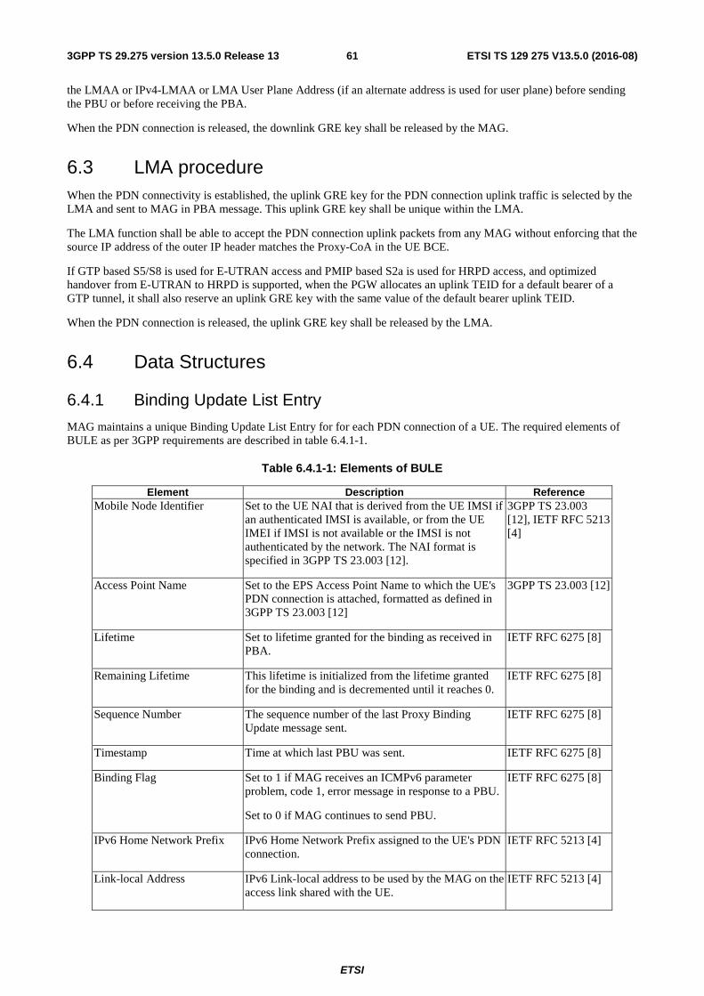
ETSI
ETSI TS 129 275 V13.5.0 (2016-08)613GPP TS 29.275 version 13.5.0 Release 13
the LMAA or IPv4-LMAA or LMA User Plane Address (if an alternate address is used for user plane) before sending the PBU or before receiving the PBA.
When the PDN connection is released, the downlink GRE key shall be released by the MAG.
6.3 LMA procedure When the PDN connectivity is established, the uplink GRE key for the PDN connection uplink traffic is selected by the LMA and sent to MAG in PBA message. This uplink GRE key shall be unique within the LMA.
The LMA function shall be able to accept the PDN connection uplink packets from any MAG without enforcing that the source IP address of the outer IP header matches the Proxy-CoA in the UE BCE.
If GTP based S5/S8 is used for E-UTRAN access and PMIP based S2a is used for HRPD access, and optimized handover from E-UTRAN to HRPD is supported, when the PGW allocates an uplink TEID for a default bearer of a GTP tunnel, it shall also reserve an uplink GRE key with the same value of the default bearer uplink TEID.
When the PDN connection is released, the uplink GRE key shall be released by the LMA.
6.4 Data Structures
6.4.1 Binding Update List Entry
MAG maintains a unique Binding Update List Entry for for each PDN connection of a UE. The required elements of BULE as per 3GPP requirements are described in table 6.4.1-1.
Table 6.4.1-1: Elements of BULE
Element Description Reference Mobile Node Identifier Set to the UE NAI that is derived from the UE IMSI if
an authenticated IMSI is available, or from the UE IMEI if IMSI is not available or the IMSI is not authenticated by the network. The NAI format is specified in 3GPP TS 23.003 [12].
3GPP TS 23.003 [12], IETF RFC 5213 [4]
Access Point Name Set to the EPS Access Point Name to which the UE's PDN connection is attached, formatted as defined in 3GPP TS 23.003 [12]
3GPP TS 23.003 [12]
Lifetime Set to lifetime granted for the binding as received in PBA.
IETF RFC 6275 [8]
Remaining Lifetime This lifetime is initialized from the lifetime granted for the binding and is decremented until it reaches 0.
IETF RFC 6275 [8]
Sequence Number The sequence number of the last Proxy Binding Update message sent.
IETF RFC 6275 [8]
Timestamp Time at which last PBU was sent. IETF RFC 6275 [8]
Binding Flag Set to 1 if MAG receives an ICMPv6 parameter problem, code 1, error message in response to a PBU.
Set to 0 if MAG continues to send PBU.
IETF RFC 6275 [8]
IPv6 Home Network Prefix IPv6 Home Network Prefix assigned to the UE's PDN connection.
IETF RFC 5213 [4]
Link-local Address IPv6 Link-local address to be used by the MAG on the access link shared with the UE.
IETF RFC 5213 [4]
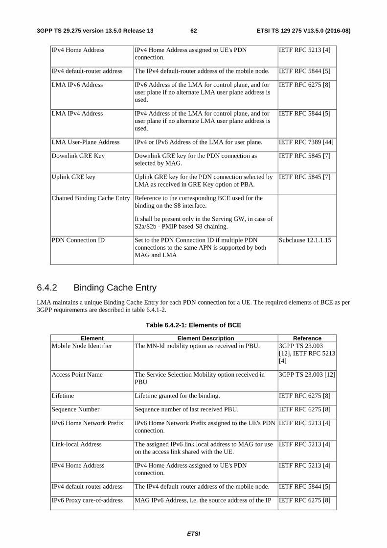
ETSI
ETSI TS 129 275 V13.5.0 (2016-08)623GPP TS 29.275 version 13.5.0 Release 13
IPv4 Home Address IPv4 Home Address assigned to UE's PDN connection.
IETF RFC 5213 [4]
IPv4 default-router address The IPv4 default-router address of the mobile node. IETF RFC 5844 [5]
LMA IPv6 Address IPv6 Address of the LMA for control plane, and for user plane if no alternate LMA user plane address is used.
IETF RFC 6275 [8]
LMA IPv4 Address IPv4 Address of the LMA for control plane, and for user plane if no alternate LMA user plane address is used.
IETF RFC 5844 [5]
LMA User-Plane Address IPv4 or IPv6 Address of the LMA for user plane. IETF RFC 7389 [44]
Downlink GRE Key Downlink GRE key for the PDN connection as selected by MAG.
IETF RFC 5845 [7]
Uplink GRE key Uplink GRE key for the PDN connection selected by LMA as received in GRE Key option of PBA.
IETF RFC 5845 [7]
Chained Binding Cache Entry Reference to the corresponding BCE used for the binding on the S8 interface.
It shall be present only in the Serving GW, in case of S2a/S2b - PMIP based-S8 chaining.
PDN Connection ID Set to the PDN Connection ID if multiple PDN connections to the same APN is supported by both MAG and LMA
Subclause 12.1.1.15
6.4.2 Binding Cache Entry
LMA maintains a unique Binding Cache Entry for each PDN connection for a UE. The required elements of BCE as per 3GPP requirements are described in table 6.4.1-2.
Table 6.4.2-1: Elements of BCE
Element Element Description Reference Mobile Node Identifier The MN-Id mobility option as received in PBU. 3GPP TS 23.003
[12], IETF RFC 5213 [4]
Access Point Name The Service Selection Mobility option received in PBU
3GPP TS 23.003 [12]
Lifetime Lifetime granted for the binding. IETF RFC 6275 [8]
Sequence Number Sequence number of last received PBU. IETF RFC 6275 [8]
IPv6 Home Network Prefix IPv6 Home Network Prefix assigned to the UE's PDN connection.
IETF RFC 5213 [4]
Link-local Address The assigned IPv6 link local address to MAG for use on the access link shared with the UE.
IETF RFC 5213 [4]
IPv4 Home Address IPv4 Home Address assigned to UE's PDN connection.
IETF RFC 5213 [4]
IPv4 default-router address The IPv4 default-router address of the mobile node. IETF RFC 5844 [5]
IPv6 Proxy care-of-address MAG IPv6 Address, i.e. the source address of the IP IETF RFC 6275 [8]
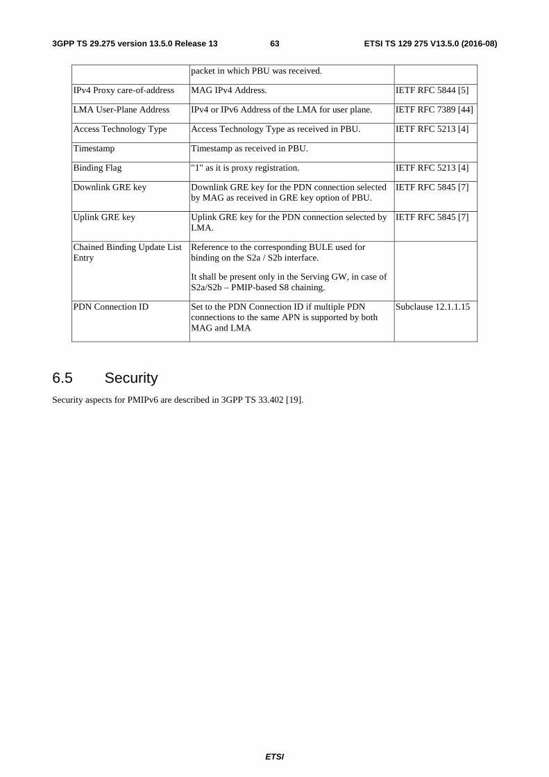
ETSI
ETSI TS 129 275 V13.5.0 (2016-08)633GPP TS 29.275 version 13.5.0 Release 13
packet in which PBU was received.
IPv4 Proxy care-of-address MAG IPv4 Address. IETF RFC 5844 [5]
LMA User-Plane Address IPv4 or IPv6 Address of the LMA for user plane. IETF RFC 7389 [44]
Access Technology Type Access Technology Type as received in PBU. IETF RFC 5213 [4]
Timestamp Timestamp as received in PBU.
Binding Flag "1" as it is proxy registration. IETF RFC 5213 [4]
Downlink GRE key Downlink GRE key for the PDN connection selected by MAG as received in GRE key option of PBU.
IETF RFC 5845 [7]
Uplink GRE key Uplink GRE key for the PDN connection selected by LMA.
IETF RFC 5845 [7]
Chained Binding Update List Entry
Reference to the corresponding BULE used for binding on the S2a / S2b interface.
It shall be present only in the Serving GW, in case of S2a/S2b – PMIP-based S8 chaining.
PDN Connection ID Set to the PDN Connection ID if multiple PDN connections to the same APN is supported by both MAG and LMA
Subclause 12.1.1.15
6.5 Security Security aspects for PMIPv6 are described in 3GPP TS 33.402 [19].
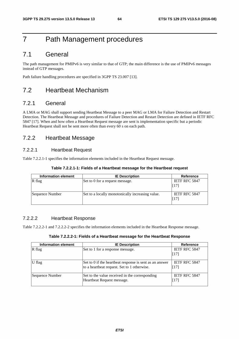
ETSI
ETSI TS 129 275 V13.5.0 (2016-08)643GPP TS 29.275 version 13.5.0 Release 13
7 Path Management procedures
7.1 General The path management for PMIPv6 is very similar to that of GTP; the main difference is the use of PMIPv6 messages instead of GTP messages.
Path failure handling procedures are specified in 3GPP TS 23.007 [13].
7.2 Heartbeat Mechanism
7.2.1 General
A LMA or MAG shall support sending Heartbeat Message to a peer MAG or LMA for Failure Detection and Restart Detection. The Heartbeat Message and procedures of Failure Detection and Restart Detection are defined in IETF RFC 5847 [17]. When and how often a Heartbeat Request message are sent is implementation specific but a periodic Heartbeat Request shall not be sent more often than every 60 s on each path.
7.2.2 Heartbeat Message
7.2.2.1 Heartbeat Request
Table 7.2.2.1-1 specifies the information elements included in the Heartbeat Request message.
Table 7.2.2.1-1: Fields of a Heartbeat message for the Heartbeat request
Information element IE Description Reference R flag Set to 0 for a request message. IETF RFC 5847
[17]
Sequence Number Set to a locally monotonically increasing value. IETF RFC 5847 [17]
7.2.2.2 Heartbeat Response
Table 7.2.2.2-1 and 7.2.2.2-2 specifies the information elements included in the Heartbeat Response message.
Table 7.2.2.2-1: Fields of a Heartbeat message for the Heartbeat Response
Information element IE Description Reference R flag Set to 1 for a response message. IETF RFC 5847
[17]
U flag Set to 0 if the heartbeat response is sent as an answer to a heartbeat request. Set to 1 otherwise.
IETF RFC 5847 [17]
Sequence Number Set to the value received in the corresponding Heartbeat Request message.
IETF RFC 5847 [17]
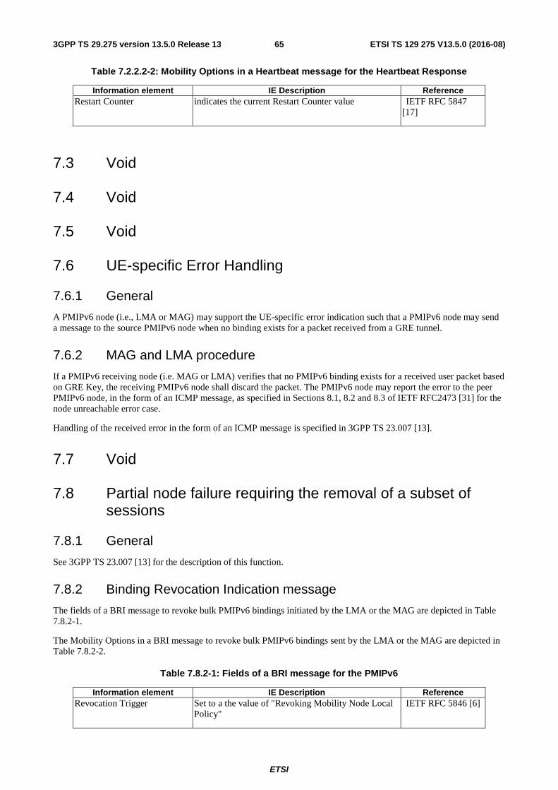
ETSI
ETSI TS 129 275 V13.5.0 (2016-08)653GPP TS 29.275 version 13.5.0 Release 13
Table 7.2.2.2-2: Mobility Options in a Heartbeat message for the Heartbeat Response
Information element IE Description Reference Restart Counter indicates the current Restart Counter value IETF RFC 5847
[17]
7.3 Void
7.4 Void
7.5 Void
7.6 UE-specific Error Handling
7.6.1 General
A PMIPv6 node (i.e., LMA or MAG) may support the UE-specific error indication such that a PMIPv6 node may send a message to the source PMIPv6 node when no binding exists for a packet received from a GRE tunnel.
7.6.2 MAG and LMA procedure
If a PMIPv6 receiving node (i.e. MAG or LMA) verifies that no PMIPv6 binding exists for a received user packet based on GRE Key, the receiving PMIPv6 node shall discard the packet. The PMIPv6 node may report the error to the peer PMIPv6 node, in the form of an ICMP message, as specified in Sections 8.1, 8.2 and 8.3 of IETF RFC2473 [31] for the node unreachable error case.
Handling of the received error in the form of an ICMP message is specified in 3GPP TS 23.007 [13].
7.7 Void
7.8 Partial node failure requiring the removal of a subset of sessions
7.8.1 General
See 3GPP TS 23.007 [13] for the description of this function.
7.8.2 Binding Revocation Indication message
The fields of a BRI message to revoke bulk PMIPv6 bindings initiated by the LMA or the MAG are depicted in Table 7.8.2-1.
The Mobility Options in a BRI message to revoke bulk PMIPv6 bindings sent by the LMA or the MAG are depicted in Table 7.8.2-2.
Table 7.8.2-1: Fields of a BRI message for the PMIPv6
Information element IE Description Reference Revocation Trigger Set to a the value of "Revoking Mobility Node Local
Policy" IETF RFC 5846 [6]
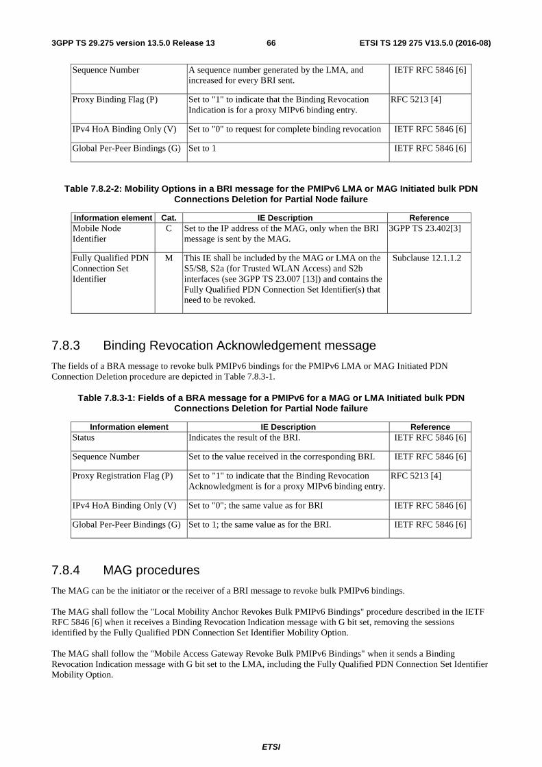
ETSI
ETSI TS 129 275 V13.5.0 (2016-08)663GPP TS 29.275 version 13.5.0 Release 13
Sequence Number A sequence number generated by the LMA, and increased for every BRI sent.
IETF RFC 5846 [6]
Proxy Binding Flag (P) Set to "1" to indicate that the Binding Revocation Indication is for a proxy MIPv6 binding entry.
RFC 5213 [4]
IPv4 HoA Binding Only (V) Set to "0" to request for complete binding revocation IETF RFC 5846 [6]
Global Per-Peer Bindings (G) Set to 1 IETF RFC 5846 [6]
Table 7.8.2-2: Mobility Options in a BRI message for the PMIPv6 LMA or MAG Initiated bulk PDN Connections Deletion for Partial Node failure
Information element Cat. IE Description Reference Mobile Node Identifier
C Set to the IP address of the MAG, only when the BRI message is sent by the MAG.
3GPP TS 23.402[3]
Fully Qualified PDN Connection Set Identifier
M This IE shall be included by the MAG or LMA on the S5/S8, S2a (for Trusted WLAN Access) and S2b interfaces (see 3GPP TS 23.007 [13]) and contains the Fully Qualified PDN Connection Set Identifier(s) that need to be revoked.
Subclause 12.1.1.2
7.8.3 Binding Revocation Acknowledgement message
The fields of a BRA message to revoke bulk PMIPv6 bindings for the PMIPv6 LMA or MAG Initiated PDN Connection Deletion procedure are depicted in Table 7.8.3-1.
Table 7.8.3-1: Fields of a BRA message for a PMIPv6 for a MAG or LMA Initiated bulk PDN Connections Deletion for Partial Node failure
Information element IE Description Reference Status Indicates the result of the BRI. IETF RFC 5846 [6]
Sequence Number Set to the value received in the corresponding BRI. IETF RFC 5846 [6]
Proxy Registration Flag (P) Set to "1" to indicate that the Binding Revocation Acknowledgment is for a proxy MIPv6 binding entry.
RFC 5213 [4]
IPv4 HoA Binding Only (V) Set to "0"; the same value as for BRI IETF RFC 5846 [6]
Global Per-Peer Bindings (G) Set to 1; the same value as for the BRI. IETF RFC 5846 [6]
7.8.4 MAG procedures
The MAG can be the initiator or the receiver of a BRI message to revoke bulk PMIPv6 bindings. The MAG shall follow the "Local Mobility Anchor Revokes Bulk PMIPv6 Bindings" procedure described in the IETF RFC 5846 [6] when it receives a Binding Revocation Indication message with G bit set, removing the sessions identified by the Fully Qualified PDN Connection Set Identifier Mobility Option. The MAG shall follow the "Mobile Access Gateway Revoke Bulk PMIPv6 Bindings" when it sends a Binding Revocation Indication message with G bit set to the LMA, including the Fully Qualified PDN Connection Set Identifier Mobility Option.

ETSI
ETSI TS 129 275 V13.5.0 (2016-08)673GPP TS 29.275 version 13.5.0 Release 13
7.8.5 LMA procedures
The LMA can be the initiator or the receiver of a BRI message to revoke bulk PMIPv6 bindings. The LMA shall follow the "Mobile Access Gateway Revokes Bulk PMIPv6 Bindings" procedure described in the IETF RFC 5846 [6] when it receives a Binding Revocation Indication message with G bit set, removing the sessions identified by the Fully Qualified PDN Connection Set Identifier Mobility Option. The LMA shall follow the "Local Mobility Anchor Revoke Bulk PMIPv6 Bindings" when it sends a Binding Revocation Indication message with G bit set to the LMA, including the Fully Qualified PDN Connection Set Identifier Mobility Option.
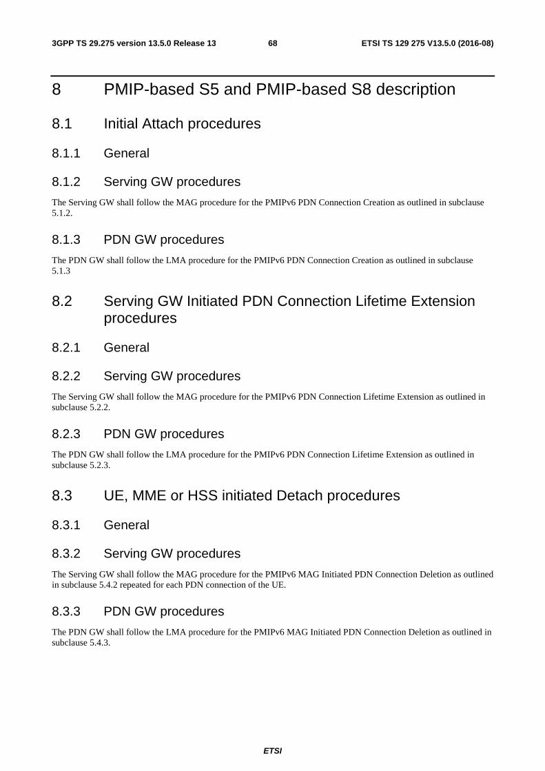
ETSI
ETSI TS 129 275 V13.5.0 (2016-08)683GPP TS 29.275 version 13.5.0 Release 13
8 PMIP-based S5 and PMIP-based S8 description
8.1 Initial Attach procedures
8.1.1 General
8.1.2 Serving GW procedures
The Serving GW shall follow the MAG procedure for the PMIPv6 PDN Connection Creation as outlined in subclause 5.1.2.
8.1.3 PDN GW procedures
The PDN GW shall follow the LMA procedure for the PMIPv6 PDN Connection Creation as outlined in subclause 5.1.3
8.2 Serving GW Initiated PDN Connection Lifetime Extension procedures
8.2.1 General
8.2.2 Serving GW procedures
The Serving GW shall follow the MAG procedure for the PMIPv6 PDN Connection Lifetime Extension as outlined in subclause 5.2.2.
8.2.3 PDN GW procedures
The PDN GW shall follow the LMA procedure for the PMIPv6 PDN Connection Lifetime Extension as outlined in subclause 5.2.3.
8.3 UE, MME or HSS initiated Detach procedures
8.3.1 General
8.3.2 Serving GW procedures
The Serving GW shall follow the MAG procedure for the PMIPv6 MAG Initiated PDN Connection Deletion as outlined in subclause 5.4.2 repeated for each PDN connection of the UE.
8.3.3 PDN GW procedures
The PDN GW shall follow the LMA procedure for the PMIPv6 MAG Initiated PDN Connection Deletion as outlined in subclause 5.4.3.
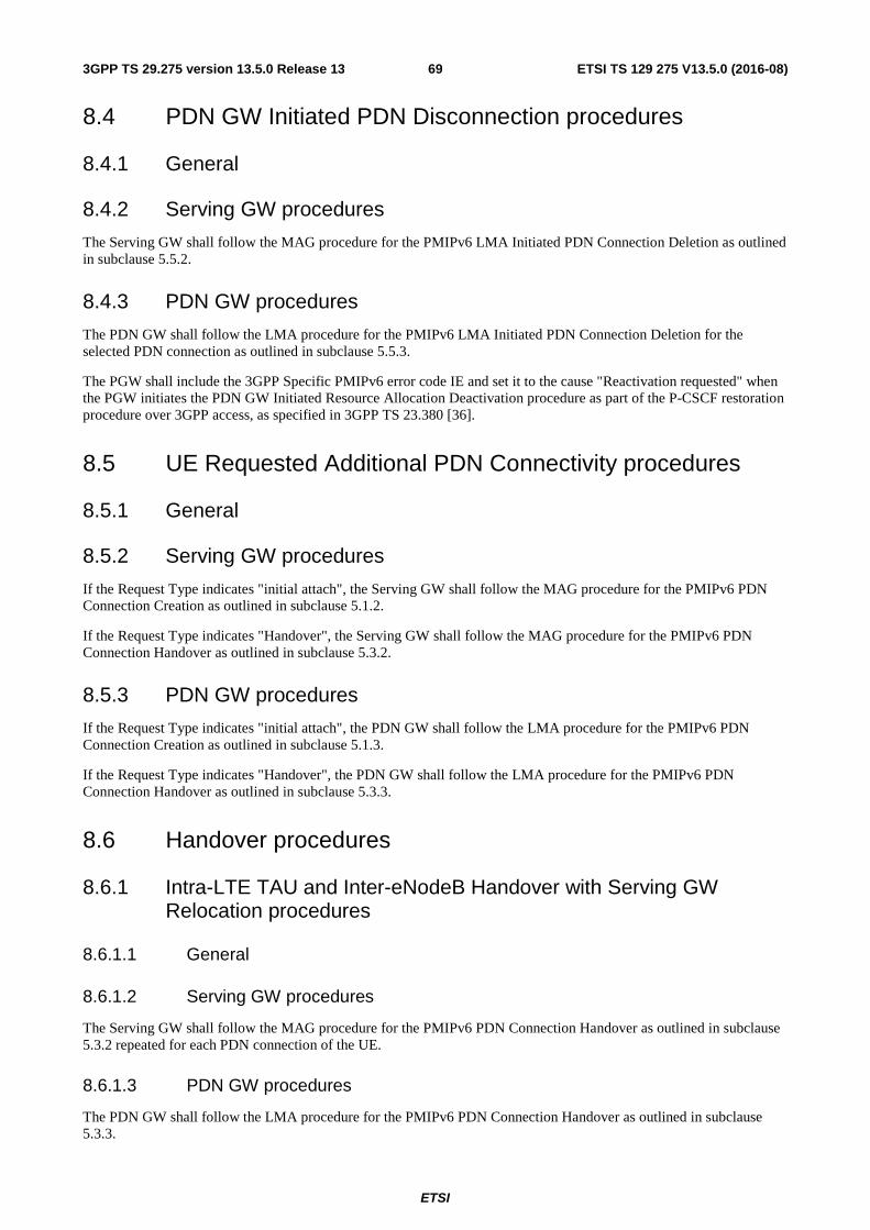
ETSI
ETSI TS 129 275 V13.5.0 (2016-08)693GPP TS 29.275 version 13.5.0 Release 13
8.4 PDN GW Initiated PDN Disconnection procedures
8.4.1 General
8.4.2 Serving GW procedures
The Serving GW shall follow the MAG procedure for the PMIPv6 LMA Initiated PDN Connection Deletion as outlined in subclause 5.5.2.
8.4.3 PDN GW procedures
The PDN GW shall follow the LMA procedure for the PMIPv6 LMA Initiated PDN Connection Deletion for the selected PDN connection as outlined in subclause 5.5.3.
The PGW shall include the 3GPP Specific PMIPv6 error code IE and set it to the cause "Reactivation requested" when the PGW initiates the PDN GW Initiated Resource Allocation Deactivation procedure as part of the P-CSCF restoration procedure over 3GPP access, as specified in 3GPP TS 23.380 [36].
8.5 UE Requested Additional PDN Connectivity procedures
8.5.1 General
8.5.2 Serving GW procedures
If the Request Type indicates "initial attach", the Serving GW shall follow the MAG procedure for the PMIPv6 PDN Connection Creation as outlined in subclause 5.1.2.
If the Request Type indicates "Handover", the Serving GW shall follow the MAG procedure for the PMIPv6 PDN Connection Handover as outlined in subclause 5.3.2.
8.5.3 PDN GW procedures
If the Request Type indicates "initial attach", the PDN GW shall follow the LMA procedure for the PMIPv6 PDN Connection Creation as outlined in subclause 5.1.3.
If the Request Type indicates "Handover", the PDN GW shall follow the LMA procedure for the PMIPv6 PDN Connection Handover as outlined in subclause 5.3.3.
8.6 Handover procedures
8.6.1 Intra-LTE TAU and Inter-eNodeB Handover with Serving GW Relocation procedures
8.6.1.1 General
8.6.1.2 Serving GW procedures
The Serving GW shall follow the MAG procedure for the PMIPv6 PDN Connection Handover as outlined in subclause 5.3.2 repeated for each PDN connection of the UE.
8.6.1.3 PDN GW procedures
The PDN GW shall follow the LMA procedure for the PMIPv6 PDN Connection Handover as outlined in subclause 5.3.3.
ETSI
ETSI TS 129 275 V13.5.0 (2016-08)703GPP TS 29.275 version 13.5.0 Release 13
8.6.2 TAU/RAU or Handover between GERAN A/Gb Mode or UTRAN Iu Mode and E-UTRAN procedures
8.6.2.1 General
8.6.2.2 Serving GW procedures
The Serving GW shall follow the MAG procedure for the PMIPv6 PDN Connection Handover as outlined in subclause 5.3.2 repeated for each PDN connection of the UE.
8.6.2.3 PDN GW procedures
The PDN GW shall follow the LMA procedure for the PMIPv6 PDN Connection Handover as outlined in subclause 5.3.3.
8.6.3 Handover from Trusted or Untrusted Non-3GPP IP Access over S2a/S2b to 3GPP Access Handover E-UTRAN over PMIP based S5/S8 without optimization procedures
8.6.3.1 General
8.6.3.2 Serving GW procedures
The Serving GW shall follow the MAG procedure for the PMIPv6 PDN Connection Handover as outlined in subclause 5.3.2 repeated for each PDN connection of the UE.
8.6.3.3 PDN GW procedures
The PDN GW shall follow the LMA procedure for the PMIPv6 PDN Connection Handover as outlined in subclause 5.3.3
8.6.4 Handover from Trusted or Untrusted Non-3GPP IP Access over S2a/S2b to 3GPP Access UTRAN/GERAN over PMIP based S5/S8 without optimization
8.6.4.1 General
8.6.4.2 Serving GW procedures
The Serving GW shall follow the MAG procedure for the PMIPv6 PDN Connection Handover as outlined in subclause 5.3.2 repeated for each PDN connection of the UE.
8.6.4.3 PDN GW procedures
The PDN GW shall follow the LMA procedure for the PMIPv6 PDN Connection Handover as outlined in subclause 5.3.3.
ETSI
ETSI TS 129 275 V13.5.0 (2016-08)713GPP TS 29.275 version 13.5.0 Release 13
8.6.5 Handover from Trusted or Untrusted Non-3GPP IP Access over S2c to 3GPP Access over PMIP based S5/S8 without optimization
8.6.5.1 General
8.6.5.2 Serving GW procedures
The Serving GW shall follow the MAG procedure for the PMIPv6 PDN Connection Handover as outlined in subclause 5.3.2 repeated for each PDN connection of the UE.
8.6.5.3 PDN GW procedures
The PDN GW shall follow the LMA procedure for the PMIPv6 PDN Connection Handover as outlined in subclause 5.3.3.
8.6.6 Void
8.6.7 Void
8.7 UE Requested PDN Disconnection procedures
8.7.1 General
8.7.2 Serving GW procedures
The Serving GW shall follow the MAG procedure for the PMIPv6 MAG Initiated PDN Connection Deletion, for the selected PDN connection as outlined in subclause 5.4.2.
8.7.3 PDN GW procedures
The PDN GW shall follow the LMA procedure for the PMIPv6 MAG Initiated PDN Connection Deletion, for the selected PDN connection as outlined in subclause 5.4.3.
8.8 IPv4 Address Allocation using DHCP
8.8.1 General
8.8.2 Serving GW procedures
The Serving GW shall follow the MAG procedure for the Proxy Mobile IPv6 PDN Connection IPv4 Address Allocation Procedure as defined in sub clause 5.6.2.
8.8.3 PDN GW procedures
The PDN GW shall follow the LMA procedure for the Proxy Mobile IPv6 PDN Connection IPv4 Address Allocation Procedure as defined in sub clause 5.6.3.
ETSI
ETSI TS 129 275 V13.5.0 (2016-08)723GPP TS 29.275 version 13.5.0 Release 13
8.9 PDN-GW Initiated IPv4 Address Delete Procedure
8.9.1 General
8.9.2 Serving GW procedures
If UE is assigned both IPv6 HNP and IPv4 HoA, the Serving GW shall follow the MAG procedure for the LMA Initiated IPv4 Address Release procedure as defined in sub clause 5.7.2.
8.9.3 PDN GW procedures
If UE is assigned both IPv6 HNP and IPv4 HoA, the PDN GW shall follow the LMA procedure for the LMA Initiated IPv4 Address Release procedure as defined in sub clause 5.7.3.
If UE is assigned only IPv4 HoA, then PDN-GW initiated PDN Disconnection procedure is initiated.
8.10 Mobile Network Prefix Allocation using DHCPv6 Prefix Delegation
8.10.1 General
8.10.2 Serving GW procedures
The Serving GW shall follow the MAG procedure for the Proxy Mobile IPv6 Mobile Network Prefix Allocation procedure as defined in subclause 5.12.2.
8.10.3 PDN GW procedures
The PDN GW shall follow the LMA procedure for the Proxy Mobile IPv6 Mobile Network Prefix Allocation procedure as defined in sub clause 5.12.3.
9 Trusted Non-3GPP Access over S2a Description
9.0 General Please refer to clause 13 for the description of the Trusted WLAN Access over S2a interface.
9.1 Initial Attach procedures
9.1.1 General
9.1.2 Trusted Non-3GPP Access procedures
In PMIPv6 mode, the Trusted Non-3GPP Access shall follow the MAG procedure for the PMIPv6 PDN Connection Creation as outlined in subclause 5.1.2.
9.1.3 PDN GW procedures
In PMIPv6 mode, the PDN GW shall follow the MAG procedure for the PMIPv6 PDN Connection Creation as outlined in subclause 5.1.3.
ETSI
ETSI TS 129 275 V13.5.0 (2016-08)733GPP TS 29.275 version 13.5.0 Release 13
The PGW may include a PGW Back-Off Time IE when rejecting the PBU with the cause "APN congestion" (see subclause 4.5.8 of 3GPP TS 23.402 [3]).
9.2 Trusted Non-3GPP Access Initiated PDN Connection Lifetime Extension procedures
9.2.1 General
9.2.2 Trusted Non-3GPP Access procedures
In PMIPv6 mode, the Trusted Non-3GPP Access shall follow the MAG procedure for the PMIPv6 PDN Connection Lifetime Extension as outlined in subclause 5.2.2.
9.2.3 PDN GW procedures
In PMIPv6 mode, the PDN GW shall follow the LMA procedure for the PMIPv6 PDN Connection Lifetime Extension as outlined in subclause 5.2.3.
9.3 UE / Trusted Non-3GPP Access Initiated Detach and UE Requested PDN Disconnection procedures
9.3.1 General
9.3.2 Trusted Non-3GPP Access procedures
In PMIPv6 mode, the Trusted Non-3GPP Access shall follow the MAG procedure for the PMIPv6 MAG Initiated PDN Connection Deletion as outlined in subclause 5.4.2 for PDN Disconnection procedure,.
For Detach the Trusted Non-3GPP Access shall follow the above repeated for each PDN connection of the UE.
9.3.3 PDN GW procedures
In PMIPv6 mode, the PDN GW shall follow the LMA procedure for the PMIPv6 MAG Initiated PDN Connection Deletion as outlined in subclause 5.4.3.
9.4 HSS / AAA Initiated Detach procedures
9.4.1 General
The HSS/AAA may initiate a detach procedure resulting in a PMIPv6 De-Registration.
9.4.2 Trusted Non-3GPP Access procedures
In PMIPv6 mode, the Trusted Non-3GPP Access shall follow the MAG procedure for the PMIPv6 MAG Initiated PDN Connection Deletion as outlined in subclause 5.4.2 repeated for each PDN connection of the UE.
9.4.3 PDN GW procedures
In PMIPv6 mode, the PDN GW shall follow the LMA procedure for the PMIPv6 MAG Initiated PDN Connection Deletion as outlined in subclause 5.4.3.
ETSI
ETSI TS 129 275 V13.5.0 (2016-08)743GPP TS 29.275 version 13.5.0 Release 13
9.5 UE Initiated Connectivity to Additional PDN procedures
9.5.1 General
9.5.2 Trusted Non-3GPP Access procedures
In PMIPv6 mode, if the Request Type indicates "initial attach", the Trusted Non-3GPP Access shall follow the MAG procedure for the PMIPv6 PDN Connection Creation as outlined in subclause 5.1.2. If the Request Type indicates "Handover", the Trusted Non-3GPP Access shall follow the MAG procedure for the PMIPv6 PDN Connection Handover as outlined in subclause 5.3.2.
9.5.3 PDN GW procedures
In PMIPv6 mode, if the Request Type indicates "initial attach", the PDN GW shall follow the LMA procedure for the PMIPv6 PDN Connection Creation as outlined in subclause 5.1.3. If the Request Type indicates "Handover", the PDN GW shall follow the LMA procedure for the PMIPv6 PDN Connection Handover as outlined in subclause 5.3.3.
If the Request Type indicates "initial attach" or "handover", the PGW may include a PGW Back-Off Time IE when rejecting the PBU with the cause "APN congestion" (see subclause 4.5.8 of 3GPP TS 23.402 [3]).
9.6 3GPP Access to Trusted Non-3GPP IP Access with PMIPv6 on S2a Handover procedures without optimization
9.6.1 General
9.6.2 Trusted Non-3GPP Access procedures
In PMIPv6 mode, the Trusted Non-3GPP Access shall follow the MAG procedure for the PMIPv6 PDN Connection Handover as outlined in subclause 5.3.2.
9.6.3 PDN GW procedures
In PMIPv6 mode, the PDN GW shall follow the LMA procedure for the PMIPv6 PDN Connection Handover as outlined in subclause 5.3.3.
If IPv6 network prefix preservation is supported at a handover from 3GPP Access with a GTP-based S5/S8 to non-3GPP Access, the LMA shall provide to the MAG the link-local address which is used by the PDN GW at the link shared with the UE in the 3GPP Access.
9.7 PDN GW Initiated Resource Allocation Deactivation procedures
9.7.1 General
9.7.2 Trusted Non-3GPP Access procedures
In PMIPv6 mode, the Trusted Non-3GPP Access shall follow the MAG procedure for the PMIPv6 LMA Initiated PDN Connection Deletion as outlined in subclause 5.5.2.
9.7.3 PDN GW procedures
In PMIPv6 mode, the PDN GW shall follow the LMA procedure for the PMIPv6 LMA Initiated PDN Connection Deletion as outlined in subclause 5.5.3.
ETSI
ETSI TS 129 275 V13.5.0 (2016-08)753GPP TS 29.275 version 13.5.0 Release 13
9.8 IPv4 Address Allocation using DHCP
9.8.1 General
9.8.2 Trusted Non-3GPP Access procedures
The Trusted Non-3GPP Access shall follow the MAG procedure for the Proxy Mobile IPv6 PDN Connection IPv4 Address Allocation Procedure as defined in sub clause 5.6.2.
9.8.3 PDN GW procedures
The PDN GW shall follow the LMA procedure for the Proxy Mobile IPv6 PDN Connection IPv4 Address Allocation Procedure as defined in sub clause 5.6.3.
9.9 PDN-GW Initiated IPv4 Address Delete Procedure
9.9.1 General
9.9.2 Trusted Non-3GPP Access procedures
If UE is assigned both IPv6 HNP and IPv4 HoA, the Trusted Non-3GPP Access shall follow the MAG procedure for the LMA Initiated IPv4 Address Release procedure as defined in sub clause 5.7.2.
9.9.3 PDN GW procedures
If UE is assigned both IPv6 HNP and IPv4 HoA, the PDN GW shall follow the LMA procedure for the LMA Initiated IPv4 Address Release procedure as defined in sub clause 5.7.3.
If UE is assigned only IPv4 HoA, then PDN-GW initiated Resource Allocation Deactivation procedure is initiated.
9.10 Optimized E-UTRAN to CDMA2000 eHRPD Handover procedure
9.10.1 General
9.10.2 CDMA2000 HRPD access procedure
In PMIPv6 mode, the CDMA2000 HRPD access shall follow the MAG procedure for the PMIPv6 PDN Connection Handover procedure as outlined in subclause 5.3.2.
9.10.3 PDN GW procedures
In PMIPv6 mode, the PDN GW shall follow the LMA procedure for the PMIPv6 PDN Connection Handover procedure as outlined in subclause 5.3.3.
ETSI
ETSI TS 129 275 V13.5.0 (2016-08)763GPP TS 29.275 version 13.5.0 Release 13
9.11 Optimized Idle Mode Mobility: E-UTRAN Access to cdma2000 eHRPD Access procedure
9.11.1 General
9.11.2 CDMA2000 eHRPD access procedure
In PMIPv6 mode, the CDMA2000 eHRPD access shall follow the MAG procedure for the PMIPv6 PDN Connection Handover procedure as outlined in subclause 5.3.2.
9.11.3 PDN GW procedures
In PMIPv6 mode, the PDN GW shall follow the LMA procedure for the PMIPv6 PDN Connection Handover procedure as outlined in subclause 5.3.3.
10 Untrusted Non-3GPP Access over S2b Description
10.1 Initial Attach procedures
10.1.1 General
If multiple authentications are supported by the network both ePDG and PDN GW shall support the corresponding procedures as specified for PAP and CHAP authentication of the UE with external networks in 3GPP TS 33.402 [19]. Multiple authentication is per PDN connection when the UE requested additional PDN connectivity as specified in subclause 10.5.
10.1.2 ePDG procedures
In PMIPv6 mode, the ePDG shall follow the MAG procedure for the PMIPv6 PDN Connection Creation as outlined in subclause 5.1.2.
If ePDG supports multiple authentication exchanges with the UE in the IKEv2 protocol, the ePDG shall send the PAP or CHAP additional authentication and authorization information received from the UE in the Additional Protocol Configuration Options IE in the PBU to the PDN-GW as specified 3GPP TS 33.402 [19]. The ePDG shall follow the multiple authentication procedures when receiving PAP or CHAP additional authentication and authorization information in the Additional Protocol Configuration Options IE in the PBA from the PDN-GW and sending the information to the UE as specified in 3GPP TS 33.402 [19].
If the UE requests the DNS IPv4/IPv6 address in the Configuration Payload (CFG_REQ) during the IPsec tunnel establishment procedure, as specified 3GPP TS 33.402 [19], and if the ePDG supports the Additional Protocol Configuration Options IE, the ePDG may include this IE in the PBU to the PDN-GW and correspondingly set "DNS IPv4/IPv6 Server Address Request" parameter. If the ePDG receives the Additional Protocol Configuration Options IE with "DNS Server IPv4/v6 Address" parameter in the PBA from the PDN-GW, the ePDG shall send this information in the Configuration Payload (CFG_REPLY) to the UE as specified in 3GPP TS 33.402 [19].
If the UE includes the P-CSCF_IP6_ADDRESS attribute, or the P-CSCF_IP4_ADDRESS attribute or both in the CFG_REQUEST configuration payload during the IPsec tunnel establishment procedure as specified in 3GPP TS 24.302 [39]), and if the ePDG supports these IKEv2 attributes and the Additional Protocol Configuration Options IE, the ePDG shall include the Additional Protocol Configuration Options IE in the PBU to the PDN-GW and correspondingly set the P-CSCF IPv6 Address Request, or P-CSCF IPv4 Address Request, or both parameters as defined in 3GPP TS 24.008 [16]. If the ePDG receives the Additional Protocol Configuration Options IE with the P-CSCF IPv4 Address, or P-CSCF IPv6 Address, or both parameters respectively in the PBA from the PDN-GW, the ePDG shall send these information in the Configuration Payload (CFG_REPLY) to the UE as specified in 3GPP TS 24.302 [39].
ETSI
ETSI TS 129 275 V13.5.0 (2016-08)773GPP TS 29.275 version 13.5.0 Release 13
If the UE includes the P-CSCF_RESELECTION_SUPPORT attribute in the CFG_REQUEST configuration payload during the IPsec tunnel establishment procedure as specified in 3GPP TS 24.302 [39], and if the ePDG supports the P-CSCF restoration extension procedure for the untrusted WLAN access (see 3GPP TS 23.380 [36]), the ePDG shall include the Additional Protocol Configuration Options IE in the PBU to the PDN-GW and correspondingly set the P-CSCF_RESELECTION_SUPPORT, as defined in 3GPP TS 24.008 [16].
10.1.3 PDN GW procedures
In PMIPv6 mode, the PDN GW shall follow the LMA procedure for the PMIPv6 PDN Connection Creation as outlined in subclause 5.1.3.
If PDN GW supports multiple authentications it shall send the PAP or CHAP additional authentication and authorization information received from the ePDG in the Additional Protocol Configuration Options IE in the PBU to the external AAA server and the PDN GW shall send the PAP or CHAP additional authentication and authorization information received from the external AAA server to the ePDG in the Additional Protocol Configuration Options IE in the PBA as specified in 3GPP TS 33.402 [19].
If the PDN-GW supports Additional Protocol Configuration Options IE and if the PDN-GW receives it with the "DNS IPv4/IPv6 Server Address Request" parameter in the PBU from the ePDG, the PGW may include the Additional Protocol Configuration Options IE in the PBA and correspondingly set "DNS IPv4/IPv6 Address" as specified in 3GPP TS 24.008 [16].
If the PDN-GW supports the Additional Protocol Configuration Options IE and if the PGW receives it with the P-CSCF IPv4 Address Request, or P-CSCF IPv6 Address Request or both parameters in the PBU from the ePDG, the PGW may include the Additional Protocol Configuration Options IE in the PBA and correspondingly set it with the P-CSCF IPv4 Address, or P-CSCF IPv6 Address, or both parameters respectively as specified in 3GPP TS 24.008 [16].
10.2 ePDG Initiated PDN Connection Lifetime Extension procedures
10.2.1 General
10.2.2 ePDG procedures
In PMIPv6 mode, the ePDG shall follow the MAG procedure for the PMIPv6 PDN Connection Lifetime Extension as outlined in subclause 5.2.2.
10.2.3 PDN GW procedures
In PMIPv6 mode, the PDN GW shall follow the LMA procedure for the PMIPv6 PDN Connection Lifetime Extension as outlined in subclause 5.2.3.
10.3 UE / ePDG Initiated Detach and UE Requested PDN Disconnection procedures
10.3.1 General
10.3.2 ePDG procedures
In PMIPv6 mode, the ePDG shall follow the MAG procedure for the PMIPv6 MAG Initiated PDN Connection Deletion as outlined in subclause 5.4.2 for PDN Disconnection procedure,
For Detach the ePDG shall follow the above repeated for each PDN connection of the UE.
ETSI
ETSI TS 129 275 V13.5.0 (2016-08)783GPP TS 29.275 version 13.5.0 Release 13
10.3.3 PDN GW procedures
In PMIPv6 mode, the PDN GW shall follow the LMA procedure for the PMIPv6 MAG Initiated PDN Connection Deletion as outlined in subclause 5.4.3.
10.4 HSS / AAA Initiated Detach procedures
10.4.1 General
The HSS/AAA may initiate a detach procedure resulting in a PMIPv6 De-Registration.
10.4.2 ePDG procedures
In PMIPv6 mode, the ePDG shall follow the MAG procedure for the PMIPv6 MAG Initiated PDN Connection Deletion as outlined in subclause 5.4.2 repeated for each PDN connection of the UE.
10.4.3 PDN GW procedures
In PMIPv6 mode, the PDN GW shall follow the LMA procedure for the PMIPv6 MAG Initiated PDN Connection Deletion as outlined in subclause 5.4.3.
10.5 UE Initiated Connectivity to Additional PDN procedures
10.5.1 General
10.5.2 ePDG procedures
In PMIPv6 mode, if the Request Type indicates "initial attach", the ePDG shall follow the MAG procedure for the PMIPv6 PDN Connection Creation as outlined in subclause 5.1.2. If the Request Type indicates "Handover", the ePDG shall follow the MAG procedure for the PMIPv6 PDN Connection Handover as outlined in subclause 5.3.2.
If the UE requests the DNS IPv4/IPv6 address in the Configuration Payload (CFG_REQ) during the IPsec tunnel establishment procedure, as specified 3GPP TS 33.402 [19], and if the ePDG supports the Additional Protocol Configuration Options IE, the ePDG may include this IE in the PBU to the PDN-GW and correspondingly set "DNS IPv4/IPv6 Server Address Request" parameter. If the ePDG receives the Additional Protocol Configuration Options IE with "DNS Server IPv4/v6 Address" parameter in the PBA from the PDN-GW, the ePDG shall send this information in the Configuration Payload (CFG_REPLY) to the UE as specified in 3GPP TS 33.402 [19].
If the UE includes the P-CSCF_IP6_ADDRESS attribute, or the P-CSCF_IP4_ADDRESS attribute or both in the CFG_REQUEST configuration payload during the IPsec tunnel establishment procedure as specified in 3GPP TS 24.302 [39]), and if the ePDG supports these IKEv2 attributes and the Additional Protocol Configuration Options IE, the ePDG shall include the Additional Protocol Configuration Options IE in the PBU to the PDN-GW and correspondingly set the P-CSCF IPv6 Address Request, or P-CSCF IPv4 Address Request, or both parameters as defined in 3GPP TS 24.008 [16]. If the ePDG receives the Additional Protocol Configuration Options IE with the P-CSCF IPv4 Address, or P-CSCF IPv6 Address, or both parameters respectively in the PBA from the PDN-GW, the ePDG shall send these information in the Configuration Payload (CFG_REPLY) to the UE as specified in 3GPP TS 24.302 [39].
If the UE includes the P-CSCF_RESELECTION_SUPPORT attribute in the CFG_REQUEST configuration payload during the IPsec tunnel establishment procedure as specified in 3GPP TS 24.302 [39], and if the ePDG supports the P-CSCF restoration extension procedure for the untrusted WLAN access (see 3GPP TS 23.380 [36]), the ePDG shall include the Additional Protocol Configuration Options IE in the PBU to the PDN-GW and correspondingly set the P-CSCF_RESELECTION_SUPPORT, as defined in 3GPP TS 24.008 [16].
ETSI
ETSI TS 129 275 V13.5.0 (2016-08)793GPP TS 29.275 version 13.5.0 Release 13
10.5.3 PDN GW procedures
In PMIPv6 mode, if the Request Type indicates "initial attach", the PDN GW shall follow the LMA procedure for the PMIPv6 PDN Connection Creation as outlined in subclause 5.1.3. If the Request Type indicates "Handover", the PDN GW shall follow the LMA procedure for the PMIPv6 PDN Connection Handover as outlined in subclause 5.3.3.
If the PDN-GW supports Additional Protocol Configuration Options IE and if the PDN-GW receives it with the "DNS IPv4/IPv6 Server Address Request" parameter in the PBU from the ePDG, the PGW may include the Additional Protocol Configuration Options IE in the PBA and correspondingly set "DNS IPv4/IPv6 Address" as specified in 3GPP TS 24.008 [16].
If the PDN-GW supports the Additional Protocol Configuration Options IE and if the PGW receives it with the P-CSCF IPv4 Address Request, or P-CSCF IPv6 Address Request or both parameters in the PBU from the ePDG, the PGW may include the Additional Protocol Configuration Options IE in the PBA and correspondingly set it with the P-CSCF IPv4 Address, or P-CSCF IPv6 Address, or both parameters respectively as specified in 3GPP TS 24.008 [16].
10.6 3GPP Access to Untrusted Non-3GPP IP Access with PMIPv6 on S2b Handover procedures without optimization
10.6.1 General
10.6.2 ePDG procedures
In PMIPv6 mode, the ePDG shall follow the MAG procedure for the PMIPv6 PDN Connection Handover as outlined in subclause 5.3.2.
If the UE includes the P-CSCF_RESELECTION_SUPPORT attribute in the CFG_REQUEST configuration payload during the IPsec tunnel establishment procedure as specified in 3GPP TS 24.302 [39], and if the ePDG supports the P-CSCF restoration extension procedure for the untrusted WLAN access (see 3GPP TS 23.380 [36]), the ePDG shall include the Additional Protocol Configuration Options IE in the PBU to the PDN-GW and correspondingly set the P-CSCF_RESELECTION_SUPPORT, as defined in 3GPP TS 24.008 [16].
10.6.3 PDN GW procedures
In PMIPv6 mode, the PDN GW shall follow the LMA procedure for the PMIPv6 PDN Connection Handover as outlined in subclause 5.3.3.
If IPv6 network prefix preservation is supported at a handover from 3GPP Access with a GTP-based S5/S8 to non-3GPP Access, the LMA shall provide to the MAG the link-local address which is used by the PDN GW at the link shared with the UE in the 3GPP Access.
10.7 PDN GW Initiated Resource Allocation Deactivation procedures
10.7.1 General
10.7.2 ePDG procedures
In PMIPv6 mode, the ePDG shall follow the MAG procedure for the PMIPv6 LMA Initiated PDN Connection Deletion as outlined in subclause 5.5.2.
10.7.3 PDN GW procedures
In PMIPv6 mode, the PDN GW shall follow the LMA procedure for the PMIPv6 LMA Initiated PDN Connection Deletion as outlined in subclause 5.5.3.
ETSI
ETSI TS 129 275 V13.5.0 (2016-08)803GPP TS 29.275 version 13.5.0 Release 13
The PGW shall include the 3GPP Specific PMIPv6 error code IE and set it to the cause "Reactivation requested" when the PGW initiates the PDN GW Initiated Resource Allocation Deactivation procedure as part of the P-CSCF restoration procedure over WLAN access, as specified in 3GPP TS 23.380 [36].
10.8 PDN-GW Initiated IPv4 Address Delete Procedure
10.8.1 General
10.8.2 ePDG procedures
If UE is assigned both IPv6 HNP and IPv4 HoA, the ePDG shall follow the MAG procedure for the LMA Initiated IPv4 Address Release procedure as defined in sub clause 5.7.2.
10.8.3 PDN GW procedures
If UE is assigned both IPv6 HNP and IPv4 HoA, the PDN GW shall follow the LMA procedure for the LMA Initiated IPv4 Address Release procedure as defined in sub clause 5.7.3.
If UE is assigned only IPv4 HoA, then PDN-GW initiated Resource Allocation Deactivation procedure is initiated.
11 S2a and S2b Chaining with PMIP-based S8 Description
11.1 Initial Attach procedures
11.1.1 General
11.1.2 ePDG / Trusted Non-3GPP Access procedures
In PMIPv6 mode, the ePDG or Trusted Non-3GPP Access shall follow the MAG procedure for the PMIPv6 PDN Connection Creation. In addition to the general procedure, it shall include the PDN GW IP address received during the authorization procedure into the PBU request, encoding it into a Vendor-Specific Option (refer to clause 12.1.1.4).
11.1.3 Serving GW procedures
In PMIPv6 mode, the Serving GW shall follow:
- the LMA procedure for the PMIPv6 PDN Connection Creation on the S2a/S2b interface. In addition to the general procedure, the Serving GW shall include the PDN GW IP address received in the PBU request into the PBA, using the same encoding (refer to clause 12.1.1.4).
- the MAG procedure for the PMIPv6 PDN Connection Creation on the S8 interface. The Serving GW shall send the PBU request to the PDN GW IP address received on the chained S2a / S2b interface.
ETSI
ETSI TS 129 275 V13.5.0 (2016-08)813GPP TS 29.275 version 13.5.0 Release 13
11.2 ePDG / Trusted Non-3GPP Access Initiated PDN Connection Lifetime Extension procedures
11.2.1 General
11.2.2 ePDG / Trusted Non-3GPP Access procedures
In PMIPv6 mode, the ePDG or Trusted Non-3GPP Access shall follow the MAG procedure for the PMIPv6 PDN Connection Lifetime Extension.
11.2.3 Serving GW procedures
In PMIPv6 mode, the Serving GW shall follow:
- the LMA procedure for the PMIPv6 PDN Connection Lifetime Extension on the S2a/S2b interface.
- the MAG procedure for the PMIPv6 PDN Connection Lifetime Extension on the S8 interface.
11.3 UE / ePDG / Trusted Non-3GPP Access Initiated Detach procedures
11.3.1 General
11.3.2 ePDG / Trusted Non-3GPP Access procedures
In PMIPv6 mode, the ePDG or Trusted Non-3GPP Access shall follow the MAG procedure for the PMIPv6 MAG Initiated PDN Connection Deletion repeated for each PDN connection of the UE.
11.3.3 Serving GW procedures
In PMIPv6 mode, the Serving GW shall follow:
- the LMA procedure for the PMIPv6 MAG Initiated PDN Connection Deletion on the S2a/S2b interface.
- the MAG procedure for the PMIPv6 MAG Initiated PDN Connection Deletion on the S8 interface.
11.4 HSS / AAA Initiated Detach procedures
11.4.1 General
The HSS/AAA may initiate a detach procedure resulting in a PMIPv6 De-Registration.
11.4.2 ePDG / Trusted Non-3GPP Access procedures
In PMIPv6 mode, the ePDG or Trusted Non-3GPP Access shall follow the MAG procedure for the PMIPv6 MAG Initiated PDN Connection Deletion repeated for each PDN connection of the UE.
11.4.3 Serving GW procedures
In PMIPv6 mode, the Serving GW shall follow:
- the LMA procedure for the PMIPv6 MAG Initiated PDN Connection Deletion on the S2a/S2b interface.
- the MAG procedure for the PMIPv6 MAG Initiated PDN Connection Deletion on the S8 interface.
ETSI
ETSI TS 129 275 V13.5.0 (2016-08)823GPP TS 29.275 version 13.5.0 Release 13
11.5 UE Initiated Connectivity to Additional PDN procedures
11.5.1 General
11.5.2 ePDG / Trusted Non-3GPP Access procedures
In PMIPv6 mode, the ePDG or Trusted Non-3GPP Access shall follow the MAG procedure for the PMIPv6 PDN Connection Creation if the Request Type indicates "initial attach", or the PMIPv6 PDN Connection Handover if the Request Type indicates "Handover". In addition to the general procedure, it shall include the PDN GW IP address received during the authorization procedure into the PBU request, encoding it to the Vendor-Specific Option (refer to clause 12.1.1.4).
11.5.3 Serving GW procedures
In PMIPv6 mode, the Serving GW shall follow:
- the LMA procedure for the PMIPv6 PDN Connection Creation if the Request Type indicates "initial attach", or the PMIPv6 PDN Connection Handover if the Request Type indicates "Handover" on the S2a/S2b interface. In addition to the general procedure, the Serving GW shall include the PDN GW IP address received in the PBU request into the PBA, using the same encoding (refer to clause 12.1.1.4).
- the MAG procedure for the PMIPv6 PDN Connection Creation if the Request Type indicates "initial attach", or the PMIPv6 PDN Connection Handover if the Request Type indicates "Handover" on the S8 interface. The Serving GW shall send the PBU request to the PDN GW IP address received on the chained S2a / S2b interface.
11.6 3GPP Access to Trusted / Untrusted Non-3GPP IP Access Handover procedures without optimization
11.6.1 General
11.6.2 ePDG / Trusted Non-3GPP Access procedures
In PMIPv6 mode, the ePDG or Trusted Non-3GPP Access shall follow the MAG procedure for the PMIPv6 PDN Connection Handover. In addition to the general procedure, it shall include the PDN GW IP address received during the authorization procedure into the PBU request, encoding it to the Vendor-Specific Option (refer to clause 12.1.1.4).
11.6.3 Serving GW procedures
In PMIPv6 mode, the Serving GW shall follow:
- the LMA procedure for the PMIPv6 PDN Connection Handover on the S2a/S2b interface. In addition to the general procedure, the Serving GW shall include the PDN GW IP address received in the PBU request into the PBA, using the same encoding (refer to clause 12.1.1.4).
- the MAG procedure for the PMIPv6 PDN Connection Handover on the S8 interface. The Serving GW shall send the PBU request to the PDN GW IP address received on the chained S2a / S2b interface.
ETSI
ETSI TS 129 275 V13.5.0 (2016-08)833GPP TS 29.275 version 13.5.0 Release 13
11.7 UE Requested PDN Disconnection procedures
11.7.1 General
11.7.2 ePDG / Trusted Non-3GPP Access procedures
In PMIPv6 mode, the ePDG or Trusted Non-3GPP Access shall follow the MAG procedure for the PMIPv6 MAG Initiated PDN Connection Deletion, for the selected PDN connection.
11.7.3 Serving GW procedures
In PMIPv6 mode, the Serving GW shall follow:
- the LMA procedure for the PMIPv6 MAG Initiated PDN Connection Deletion, for the selected PDN connection on the S2a/S2b interface.
- the MAG procedure for the PMIPv6 MAG Initiated PDN Connection Deletion, for the selected PDN connection on the S8 interface.
11.8 PDN GW Initiated Resource Allocation Deactivation procedures
11.8.1 General
11.8.2 ePDG / Trusted Non-3GPP Access procedures
In PMIPv6 mode, the ePDG or Trusted Non-3GPP Access shall follow the MAG procedure for the PMIPv6 LMA Initiated PDN Connection Deletion.
11.8.3 Serving GW procedures
In PMIPv6 mode, the Serving GW shall follow:
- the MAG procedure for the PMIPv6 LMA Initiated PDN Connection Deletion on the S8 interface.
- the LMA procedure for the PMIPv6 LMA Initiated PDN Connection Deletion on the S2a/S2b interface.
12 Information Elements
12.1 Additional Proxy Mobile IPv6 Information Elements
12.1.1 3GPP-Specific PMIPv6 Information Elements
12.1.1.0 General
This specification requires the encoding of additional 3GPP-specific Information Elements for PMIPv6 with the 3GPP Mobility Option, as defined by 3GPP TS 29.282 [24]. The 3GPP specific Information Elements defined by this specification are listed in the table 12.1.1.0-1.
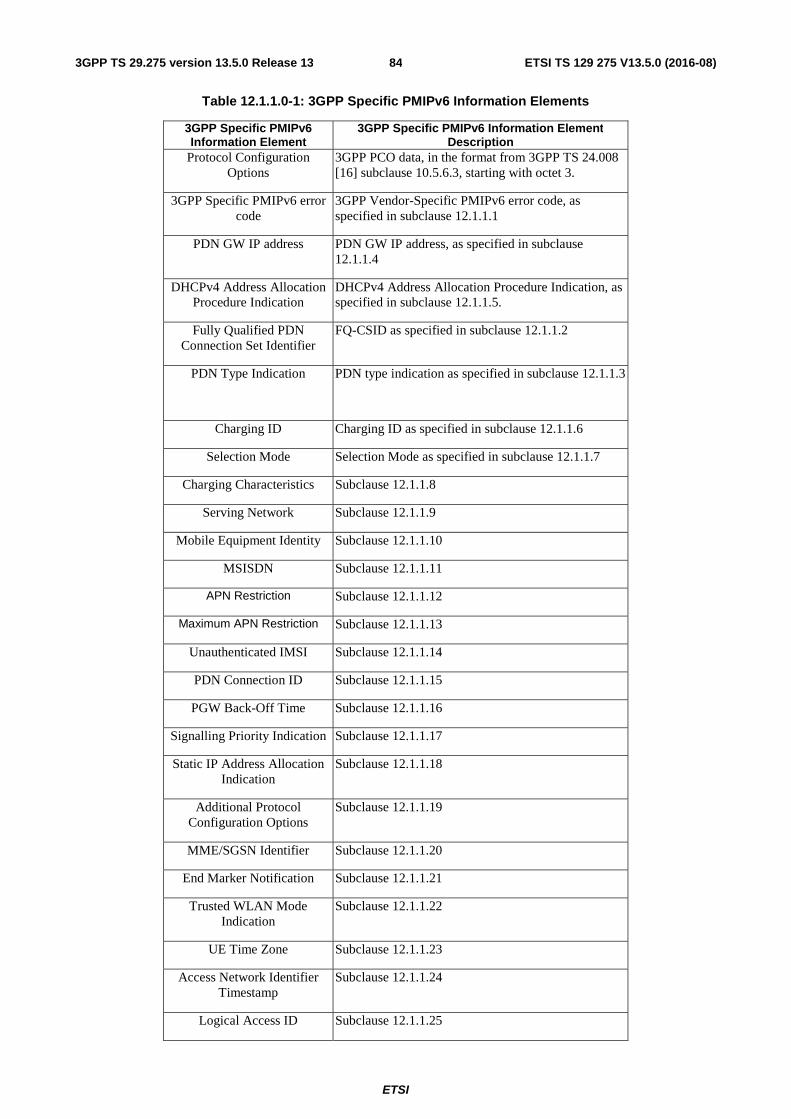
ETSI
ETSI TS 129 275 V13.5.0 (2016-08)843GPP TS 29.275 version 13.5.0 Release 13
Table 12.1.1.0-1: 3GPP Specific PMIPv6 Information Elements
3GPP Specific PMIPv6 Information Element
3GPP Specific PMIPv6 Information Element Description
Protocol Configuration Options
3GPP PCO data, in the format from 3GPP TS 24.008 [16] subclause 10.5.6.3, starting with octet 3.
3GPP Specific PMIPv6 error code
3GPP Vendor-Specific PMIPv6 error code, as specified in subclause 12.1.1.1
PDN GW IP address PDN GW IP address, as specified in subclause 12.1.1.4
DHCPv4 Address Allocation Procedure Indication
DHCPv4 Address Allocation Procedure Indication, as specified in subclause 12.1.1.5.
Fully Qualified PDN Connection Set Identifier
FQ-CSID as specified in subclause 12.1.1.2
PDN Type Indication PDN type indication as specified in subclause 12.1.1.3
Charging ID Charging ID as specified in subclause 12.1.1.6
Selection Mode Selection Mode as specified in subclause 12.1.1.7
Charging Characteristics Subclause 12.1.1.8
Serving Network Subclause 12.1.1.9
Mobile Equipment Identity Subclause 12.1.1.10
MSISDN Subclause 12.1.1.11
APN Restriction Subclause 12.1.1.12
Maximum APN Restriction Subclause 12.1.1.13
Unauthenticated IMSI Subclause 12.1.1.14
PDN Connection ID Subclause 12.1.1.15
PGW Back-Off Time Subclause 12.1.1.16
Signalling Priority Indication Subclause 12.1.1.17
Static IP Address Allocation Indication
Subclause 12.1.1.18
Additional Protocol Configuration Options
Subclause 12.1.1.19
MME/SGSN Identifier Subclause 12.1.1.20
End Marker Notification Subclause 12.1.1.21
Trusted WLAN Mode Indication
Subclause 12.1.1.22
UE Time Zone Subclause 12.1.1.23
Access Network Identifier Timestamp
Subclause 12.1.1.24
Logical Access ID Subclause 12.1.1.25
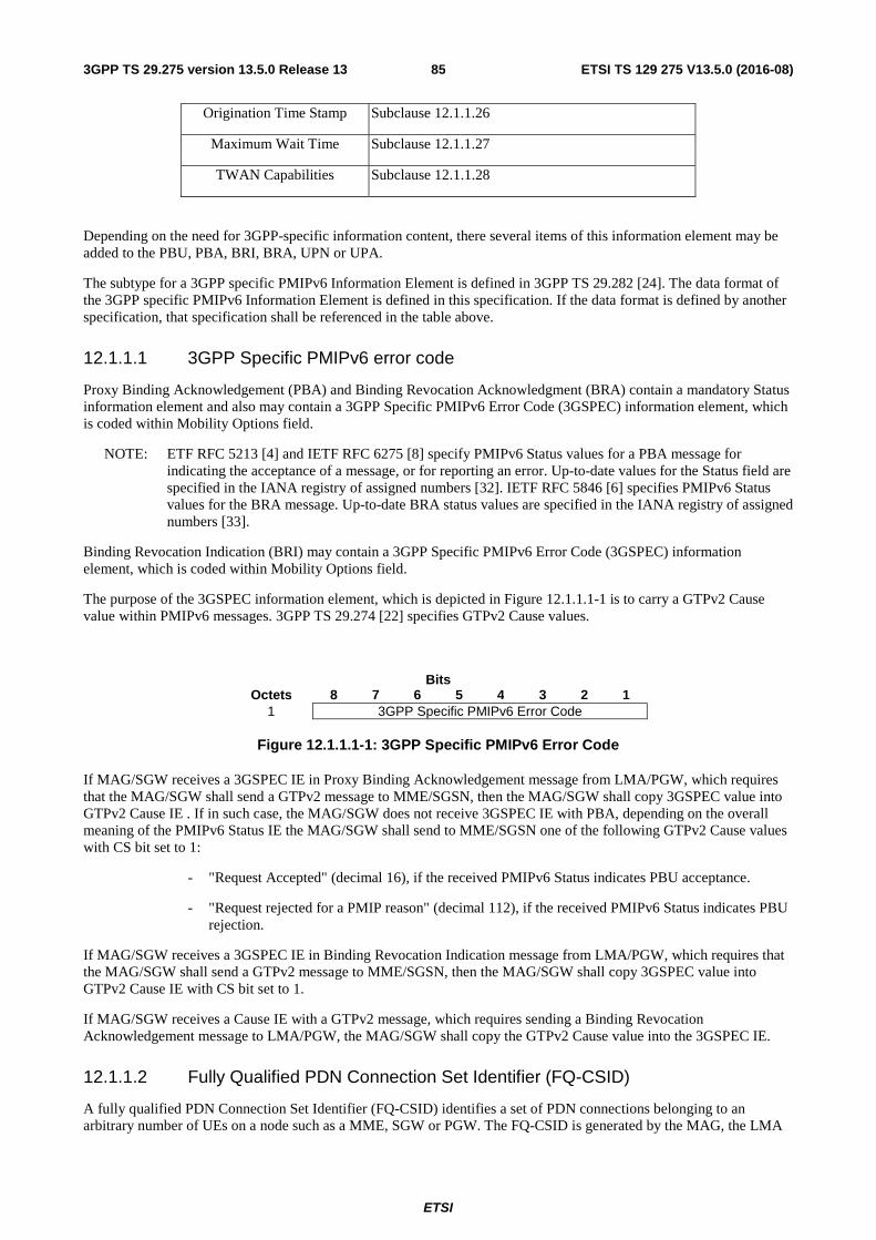
ETSI
ETSI TS 129 275 V13.5.0 (2016-08)853GPP TS 29.275 version 13.5.0 Release 13
Origination Time Stamp Subclause 12.1.1.26
Maximum Wait Time Subclause 12.1.1.27
TWAN Capabilities Subclause 12.1.1.28
Depending on the need for 3GPP-specific information content, there several items of this information element may be added to the PBU, PBA, BRI, BRA, UPN or UPA.
The subtype for a 3GPP specific PMIPv6 Information Element is defined in 3GPP TS 29.282 [24]. The data format of the 3GPP specific PMIPv6 Information Element is defined in this specification. If the data format is defined by another specification, that specification shall be referenced in the table above.
12.1.1.1 3GPP Specific PMIPv6 error code
Proxy Binding Acknowledgement (PBA) and Binding Revocation Acknowledgment (BRA) contain a mandatory Status information element and also may contain a 3GPP Specific PMIPv6 Error Code (3GSPEC) information element, which is coded within Mobility Options field.
NOTE: ETF RFC 5213 [4] and IETF RFC 6275 [8] specify PMIPv6 Status values for a PBA message for indicating the acceptance of a message, or for reporting an error. Up-to-date values for the Status field are specified in the IANA registry of assigned numbers [32]. IETF RFC 5846 [6] specifies PMIPv6 Status values for the BRA message. Up-to-date BRA status values are specified in the IANA registry of assigned numbers [33].
Binding Revocation Indication (BRI) may contain a 3GPP Specific PMIPv6 Error Code (3GSPEC) information element, which is coded within Mobility Options field.
The purpose of the 3GSPEC information element, which is depicted in Figure 12.1.1.1-1 is to carry a GTPv2 Cause value within PMIPv6 messages. 3GPP TS 29.274 [22] specifies GTPv2 Cause values.
Bits Octets 8 7 6 5 4 3 2 1
1 3GPP Specific PMIPv6 Error Code
Figure 12.1.1.1-1: 3GPP Specific PMIPv6 Error Code
If MAG/SGW receives a 3GSPEC IE in Proxy Binding Acknowledgement message from LMA/PGW, which requires that the MAG/SGW shall send a GTPv2 message to MME/SGSN, then the MAG/SGW shall copy 3GSPEC value into GTPv2 Cause IE . If in such case, the MAG/SGW does not receive 3GSPEC IE with PBA, depending on the overall meaning of the PMIPv6 Status IE the MAG/SGW shall send to MME/SGSN one of the following GTPv2 Cause values with CS bit set to 1:
- "Request Accepted" (decimal 16), if the received PMIPv6 Status indicates PBU acceptance.
- "Request rejected for a PMIP reason" (decimal 112), if the received PMIPv6 Status indicates PBU rejection.
If MAG/SGW receives a 3GSPEC IE in Binding Revocation Indication message from LMA/PGW, which requires that the MAG/SGW shall send a GTPv2 message to MME/SGSN, then the MAG/SGW shall copy 3GSPEC value into GTPv2 Cause IE with CS bit set to 1.
If MAG/SGW receives a Cause IE with a GTPv2 message, which requires sending a Binding Revocation Acknowledgement message to LMA/PGW, the MAG/SGW shall copy the GTPv2 Cause value into the 3GSPEC IE.
12.1.1.2 Fully Qualified PDN Connection Set Identifier (FQ-CSID)
A fully qualified PDN Connection Set Identifier (FQ-CSID) identifies a set of PDN connections belonging to an arbitrary number of UEs on a node such as a MME, SGW or PGW. The FQ-CSID is generated by the MAG, the LMA
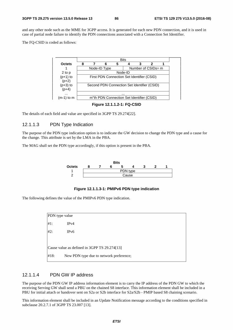
ETSI
ETSI TS 129 275 V13.5.0 (2016-08)863GPP TS 29.275 version 13.5.0 Release 13
and any other node such as the MME for 3GPP access. It is generated for each new PDN connection, and it is used in case of partial node failure to identify the PDN connections associated with a Connection Set Identifier.
The FQ-CSID is coded as follows:
Bits Octets 8 7 6 5 4 3 2 1 1 Node-ID Type Number of CSIDs= m 2 to p Node-ID (p+1) to
(p+2) First PDN Connection Set Identifier (CSID)
(p+3) to (p+4)
Second PDN Connection Set Identifier (CSID)
... ... (m-1) to m m"th PDN Connection Set Identifier (CSID)
Figure 12.1.1.2-1: FQ-CSID
The details of each field and value are specified in 3GPP TS 29.274[22].
12.1.1.3 PDN Type Indication
The purpose of the PDN type indication option is to indicate the GW decision to change the PDN type and a cause for the change. This attribute is set by the LMA in the PBA.
The MAG shall set the PDN type accordingly, if this option is present in the PBA.
Bits Octets 8 7 6 5 4 3 2 1
1 PDN type 2 Cause
Figure 12.1.1.3-1: PMIPv6 PDN type indication
The following defines the value of the PMIPv6 PDN type indication.
PDN type value
#1: IPv4
#2: IPv6
Cause value as defined in 3GPP TS 29.274[13]
#18: New PDN type due to network preference;
12.1.1.4 PDN GW IP address
The purpose of the PDN GW IP address information element is to carry the IP address of the PDN GW to which the receiving Serving GW shall send a PBU on the chained S8 interface. This information element shall be included in a PBU for initial attach or handover sent on S2a or S2b interface for S2a/S2b - PMIP based S8 chaining scenario.
This information element shall be included in an Update Notification message according to the conditions specified in subclause 20.2.7.1 of 3GPP TS 23.007 [13].
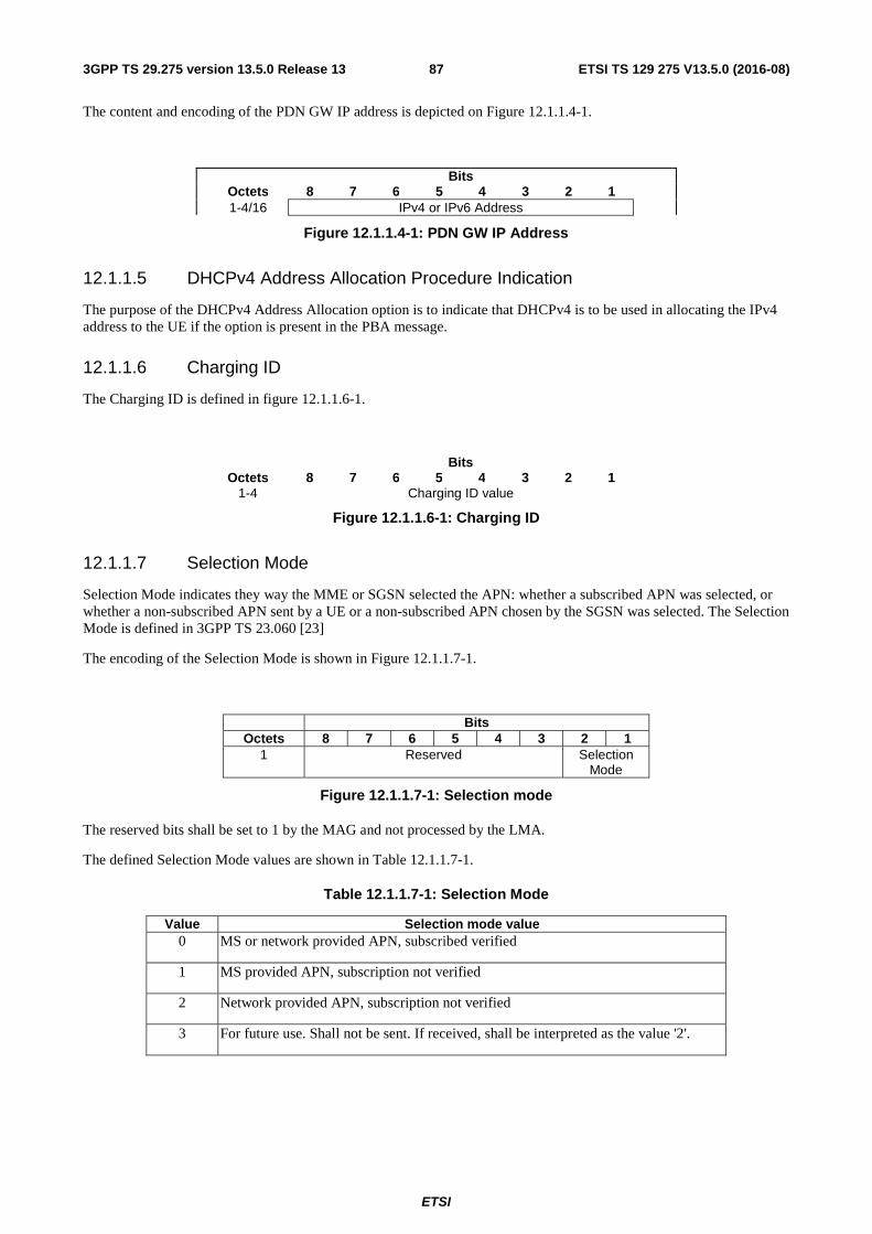
ETSI
ETSI TS 129 275 V13.5.0 (2016-08)873GPP TS 29.275 version 13.5.0 Release 13
The content and encoding of the PDN GW IP address is depicted on Figure 12.1.1.4-1.
Bits Octets 8 7 6 5 4 3 2 1 1-4/16 IPv4 or IPv6 Address
Figure 12.1.1.4-1: PDN GW IP Address
12.1.1.5 DHCPv4 Address Allocation Procedure Indication
The purpose of the DHCPv4 Address Allocation option is to indicate that DHCPv4 is to be used in allocating the IPv4 address to the UE if the option is present in the PBA message.
12.1.1.6 Charging ID
The Charging ID is defined in figure 12.1.1.6-1.
Bits Octets 8 7 6 5 4 3 2 1 1-4 Charging ID value
Figure 12.1.1.6-1: Charging ID
12.1.1.7 Selection Mode
Selection Mode indicates they way the MME or SGSN selected the APN: whether a subscribed APN was selected, or whether a non-subscribed APN sent by a UE or a non-subscribed APN chosen by the SGSN was selected. The Selection Mode is defined in 3GPP TS 23.060 [23]
The encoding of the Selection Mode is shown in Figure 12.1.1.7-1.
Bits Octets 8 7 6 5 4 3 2 1
1 Reserved Selection Mode
Figure 12.1.1.7-1: Selection mode
The reserved bits shall be set to 1 by the MAG and not processed by the LMA.
The defined Selection Mode values are shown in Table 12.1.1.7-1.
Table 12.1.1.7-1: Selection Mode
Value Selection mode value 0 MS or network provided APN, subscribed verified
1 MS provided APN, subscription not verified
2 Network provided APN, subscription not verified
3 For future use. Shall not be sent. If received, shall be interpreted as the value '2'.
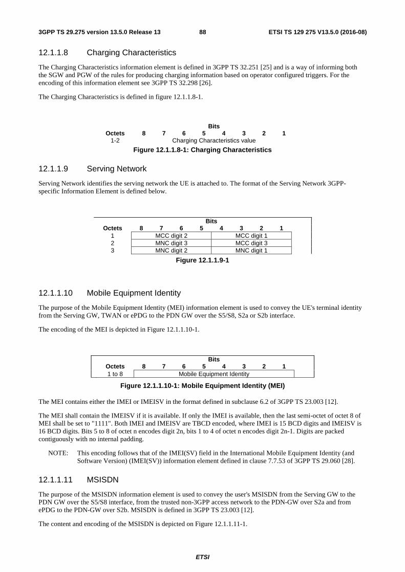
ETSI
ETSI TS 129 275 V13.5.0 (2016-08)883GPP TS 29.275 version 13.5.0 Release 13
12.1.1.8 Charging Characteristics
The Charging Characteristics information element is defined in 3GPP TS 32.251 [25] and is a way of informing both the SGW and PGW of the rules for producing charging information based on operator configured triggers. For the encoding of this information element see 3GPP TS 32.298 [26].
The Charging Characteristics is defined in figure 12.1.1.8-1.
Bits Octets 8 7 6 5 4 3 2 1 1-2 Charging Characteristics value
Figure 12.1.1.8-1: Charging Characteristics
12.1.1.9 Serving Network
Serving Network identifies the serving network the UE is attached to. The format of the Serving Network 3GPP-specific Information Element is defined below.
Bits Octets 8 7 6 5 4 3 2 1
1 MCC digit 2 MCC digit 1 2 MNC digit 3 MCC digit 3 3 MNC digit 2 MNC digit 1
Figure 12.1.1.9-1
12.1.1.10 Mobile Equipment Identity
The purpose of the Mobile Equipment Identity (MEI) information element is used to convey the UE's terminal identity from the Serving GW, TWAN or ePDG to the PDN GW over the S5/S8, S2a or S2b interface.
The encoding of the MEI is depicted in Figure 12.1.1.10-1.
Bits Octets 8 7 6 5 4 3 2 1 1 to 8 Mobile Equipment Identity
Figure 12.1.1.10-1: Mobile Equipment Identity (MEI)
The MEI contains either the IMEI or IMEISV in the format defined in subclause 6.2 of 3GPP TS 23.003 [12].
The MEI shall contain the IMEISV if it is available. If only the IMEI is available, then the last semi-octet of octet 8 of MEI shall be set to "1111". Both IMEI and IMEISV are TBCD encoded, where IMEI is 15 BCD digits and IMEISV is 16 BCD digits. Bits 5 to 8 of octet n encodes digit 2n, bits 1 to 4 of octet n encodes digit 2n-1. Digits are packed contiguously with no internal padding.
NOTE: This encoding follows that of the IMEI(SV) field in the International Mobile Equipment Identity (and Software Version) (IMEI(SV)) information element defined in clause 7.7.53 of 3GPP TS 29.060 [28].
12.1.1.11 MSISDN
The purpose of the MSISDN information element is used to convey the user's MSISDN from the Serving GW to the PDN GW over the S5/S8 interface, from the trusted non-3GPP access network to the PDN-GW over S2a and from ePDG to the PDN-GW over S2b. MSISDN is defined in 3GPP TS 23.003 [12].
The content and encoding of the MSISDN is depicted on Figure 12.1.1.11-1.
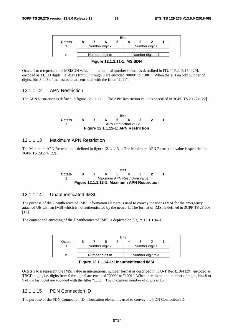
ETSI
ETSI TS 129 275 V13.5.0 (2016-08)893GPP TS 29.275 version 13.5.0 Release 13
Bits Octets 8 7 6 5 4 3 2 1 1 Number digit 2 Number digit 1 n Number digit m Number digit m-1
Figure 12.1.1.11-1: MSISDN
Octets 1 to n represent the MSISDN value in international number format as described in ITU-T Rec E.164 [29], encoded as TBCD digits, i.e. digits from 0 through 9 are encoded "0000" to "1001". When there is an odd number of digits, bits 8 to 5 of the last octet are encoded with the filler "1111".
12.1.1.12 APN Restriction
The APN Restriction is defined in figure 12.1.1.12-1. The APN Restriction value is specified in 3GPP TS 29.274 [22].
Bits Octets 8 7 6 5 4 3 2 1 1 APN Restriction value
Figure 12.1.1.12-1: APN Restriction
12.1.1.13 Maximum APN Restriction
The Maximum APN Restriction is defined in figure 12.1.1.13-1. The Maximum APN Restriction value is specified in 3GPP TS 29.274 [22].
Bits Octets 8 7 6 5 4 3 2 1 1 Maximum APN Restriction value
Figure 12.1.1.13-1: Maximum APN Restriction
12.1.1.14 Unauthenticated IMSI
The purpose of the Unauthenticated IMSI information element is used to convey the user's IMSI for the emergency attached UE with an IMSI which is not authenticated by the network. The format of IMSI is defined in 3GPP TS 23.003 [12].
The content and encoding of the Unauthenticated IMSI is depicted on Figure 12.1.1.14-1.
Bits Octets 8 7 6 5 4 3 2 1
1 Number digit 2 Number digit 1
n Number digit m Number digit m-1
Figure 12.1.1.14-1: Unauthenticated IMSI
Octets 1 to n represent the IMSI value in international number format as described in ITU-T Rec E.164 [29], encoded as TBCD digits, i.e. digits from 0 through 9 are encoded "0000" to "1001". When there is an odd number of digits, bits 8 to 5 of the last octet are encoded with the filler "1111". The maximum number of digits is 15.
12.1.1.15 PDN Connection ID
The purpose of the PDN Connection ID information element is used to convey the PDN Connection ID.
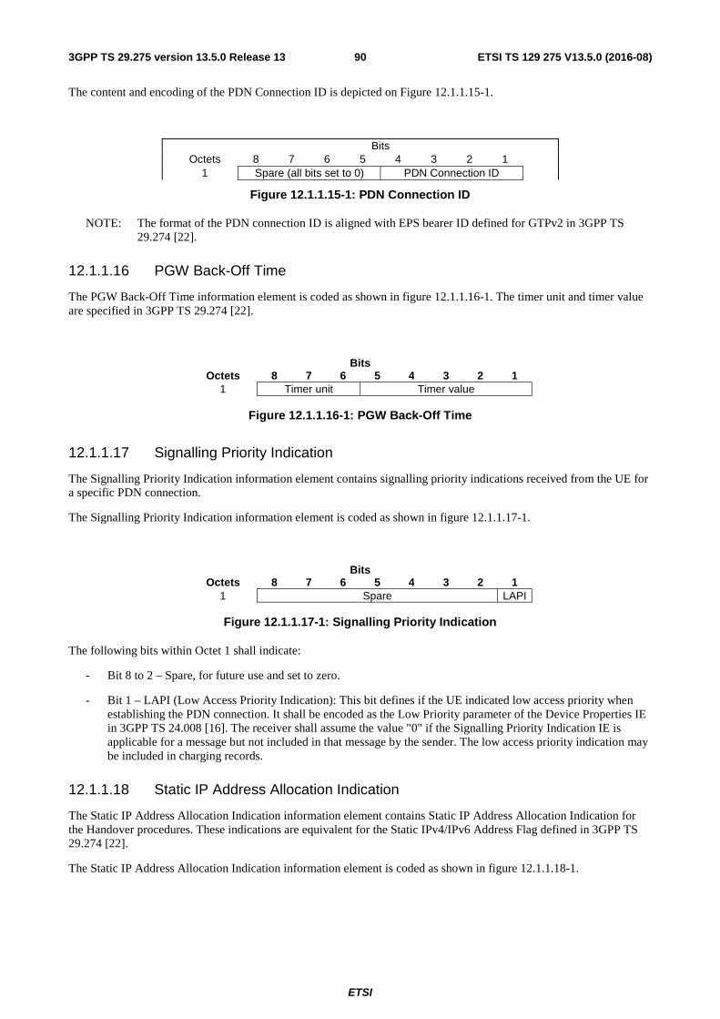
ETSI
ETSI TS 129 275 V13.5.0 (2016-08)903GPP TS 29.275 version 13.5.0 Release 13
The content and encoding of the PDN Connection ID is depicted on Figure 12.1.1.15-1.
Bits Octets 8 7 6 5 4 3 2 1
1 Spare (all bits set to 0) PDN Connection ID
Figure 12.1.1.15-1: PDN Connection ID
NOTE: The format of the PDN connection ID is aligned with EPS bearer ID defined for GTPv2 in 3GPP TS 29.274 [22].
12.1.1.16 PGW Back-Off Time
The PGW Back-Off Time information element is coded as shown in figure 12.1.1.16-1. The timer unit and timer value are specified in 3GPP TS 29.274 [22].
Bits Octets 8 7 6 5 4 3 2 1
1 Timer unit Timer value
Figure 12.1.1.16-1: PGW Back-Off Time
12.1.1.17 Signalling Priority Indication
The Signalling Priority Indication information element contains signalling priority indications received from the UE for a specific PDN connection.
The Signalling Priority Indication information element is coded as shown in figure 12.1.1.17-1.
Bits Octets 8 7 6 5 4 3 2 1
1 Spare LAPI
Figure 12.1.1.17-1: Signalling Priority Indication
The following bits within Octet 1 shall indicate:
- Bit 8 to 2 – Spare, for future use and set to zero.
- Bit 1 – LAPI (Low Access Priority Indication): This bit defines if the UE indicated low access priority when establishing the PDN connection. It shall be encoded as the Low Priority parameter of the Device Properties IE in 3GPP TS 24.008 [16]. The receiver shall assume the value "0" if the Signalling Priority Indication IE is applicable for a message but not included in that message by the sender. The low access priority indication may be included in charging records.
12.1.1.18 Static IP Address Allocation Indication
The Static IP Address Allocation Indication information element contains Static IP Address Allocation Indication for the Handover procedures. These indications are equivalent for the Static IPv4/IPv6 Address Flag defined in 3GPP TS 29.274 [22].
The Static IP Address Allocation Indication information element is coded as shown in figure 12.1.1.18-1.
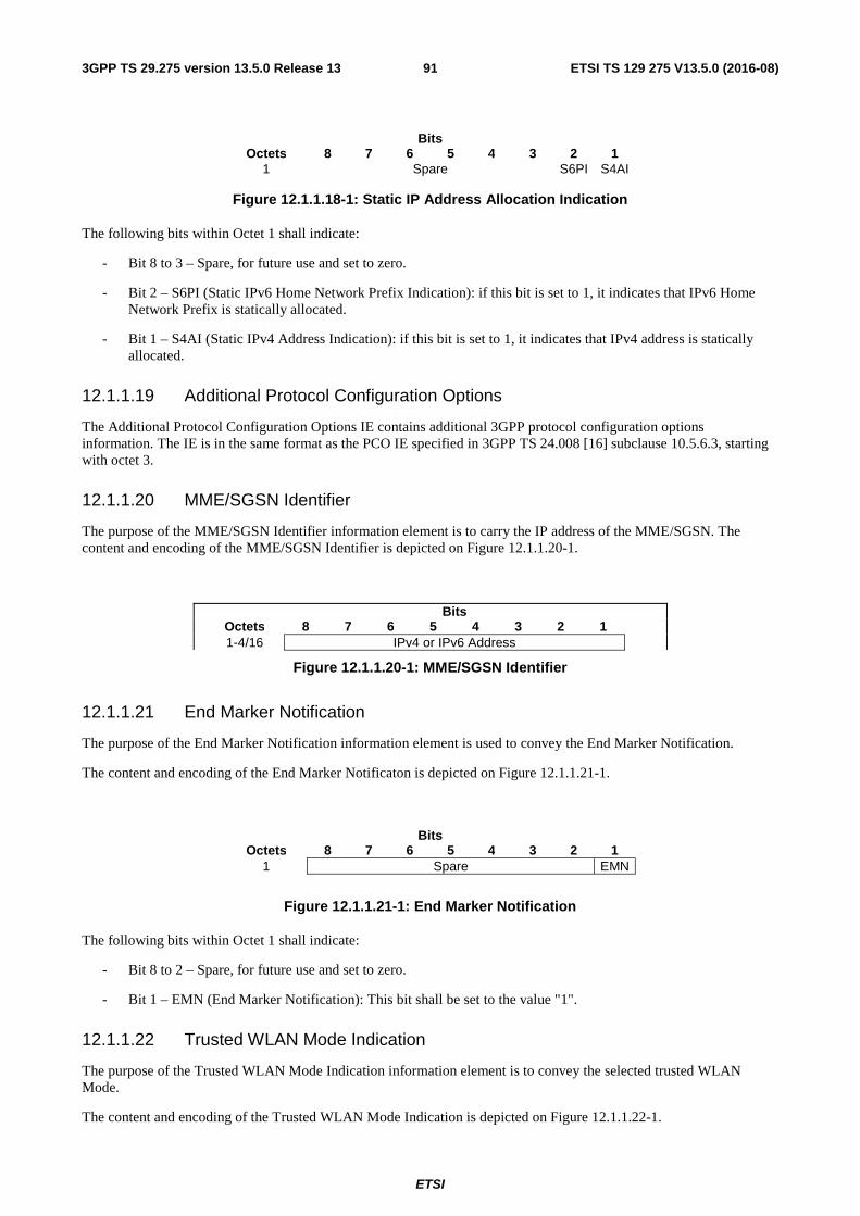
ETSI
ETSI TS 129 275 V13.5.0 (2016-08)913GPP TS 29.275 version 13.5.0 Release 13
Bits Octets 8 7 6 5 4 3 2 1
1 Spare S6PI S4AI
Figure 12.1.1.18-1: Static IP Address Allocation Indication
The following bits within Octet 1 shall indicate:
- Bit 8 to 3 – Spare, for future use and set to zero.
- Bit 2 – S6PI (Static IPv6 Home Network Prefix Indication): if this bit is set to 1, it indicates that IPv6 Home Network Prefix is statically allocated.
- Bit 1 – S4AI (Static IPv4 Address Indication): if this bit is set to 1, it indicates that IPv4 address is statically allocated.
12.1.1.19 Additional Protocol Configuration Options
The Additional Protocol Configuration Options IE contains additional 3GPP protocol configuration options information. The IE is in the same format as the PCO IE specified in 3GPP TS 24.008 [16] subclause 10.5.6.3, starting with octet 3.
12.1.1.20 MME/SGSN Identifier
The purpose of the MME/SGSN Identifier information element is to carry the IP address of the MME/SGSN. The content and encoding of the MME/SGSN Identifier is depicted on Figure 12.1.1.20-1.
Bits Octets 8 7 6 5 4 3 2 1 1-4/16 IPv4 or IPv6 Address
Figure 12.1.1.20-1: MME/SGSN Identifier
12.1.1.21 End Marker Notification
The purpose of the End Marker Notification information element is used to convey the End Marker Notification.
The content and encoding of the End Marker Notificaton is depicted on Figure 12.1.1.21-1.
Bits Octets 8 7 6 5 4 3 2 1
1 Spare EMN
Figure 12.1.1.21-1: End Marker Notification
The following bits within Octet 1 shall indicate:
- Bit 8 to 2 – Spare, for future use and set to zero.
- Bit 1 – EMN (End Marker Notification): This bit shall be set to the value "1".
12.1.1.22 Trusted WLAN Mode Indication
The purpose of the Trusted WLAN Mode Indication information element is to convey the selected trusted WLAN Mode.
The content and encoding of the Trusted WLAN Mode Indication is depicted on Figure 12.1.1.22-1.
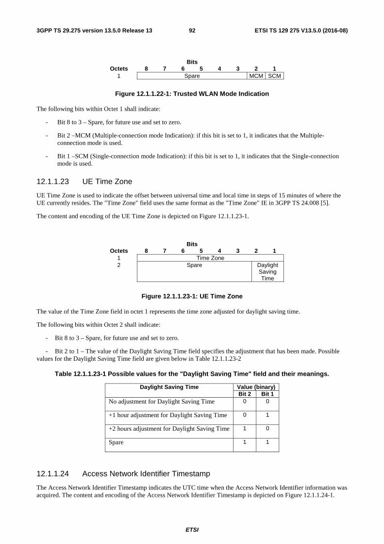
ETSI
ETSI TS 129 275 V13.5.0 (2016-08)923GPP TS 29.275 version 13.5.0 Release 13
Bits Octets 8 7 6 5 4 3 2 1
1 Spare MCM SCM
Figure 12.1.1.22-1: Trusted WLAN Mode Indication
The following bits within Octet 1 shall indicate:
- Bit 8 to 3 – Spare, for future use and set to zero.
- Bit 2 –MCM (Multiple-connection mode Indication): if this bit is set to 1, it indicates that the Multiple-connection mode is used.
- Bit 1 –SCM (Single-connection mode Indication): if this bit is set to 1, it indicates that the Single-connection mode is used.
12.1.1.23 UE Time Zone
UE Time Zone is used to indicate the offset between universal time and local time in steps of 15 minutes of where the UE currently resides. The "Time Zone" field uses the same format as the "Time Zone" IE in 3GPP TS 24.008 [5].
The content and encoding of the UE Time Zone is depicted on Figure 12.1.1.23-1.
Bits Octets 8 7 6 5 4 3 2 1
1 Time Zone 2 Spare Daylight
Saving Time
Figure 12.1.1.23-1: UE Time Zone
The value of the Time Zone field in octet 1 represents the time zone adjusted for daylight saving time.
The following bits within Octet 2 shall indicate:
- Bit 8 to 3 – Spare, for future use and set to zero.
- Bit 2 to 1 – The value of the Daylight Saving Time field specifies the adjustment that has been made. Possible values for the Daylight Saving Time field are given below in Table 12.1.1.23-2
Table 12.1.1.23-1 Possible values for the "Daylight Saving Time" field and their meanings.
Daylight Saving Time Value (binary) Bit 2 Bit 1
No adjustment for Daylight Saving Time 0 0
+1 hour adjustment for Daylight Saving Time 0 1
+2 hours adjustment for Daylight Saving Time 1 0
Spare 1 1
12.1.1.24 Access Network Identifier Timestamp
The Access Network Identifier Timestamp indicates the UTC time when the Access Network Identifier information was acquired. The content and encoding of the Access Network Identifier Timestamp is depicted on Figure 12.1.1.24-1.
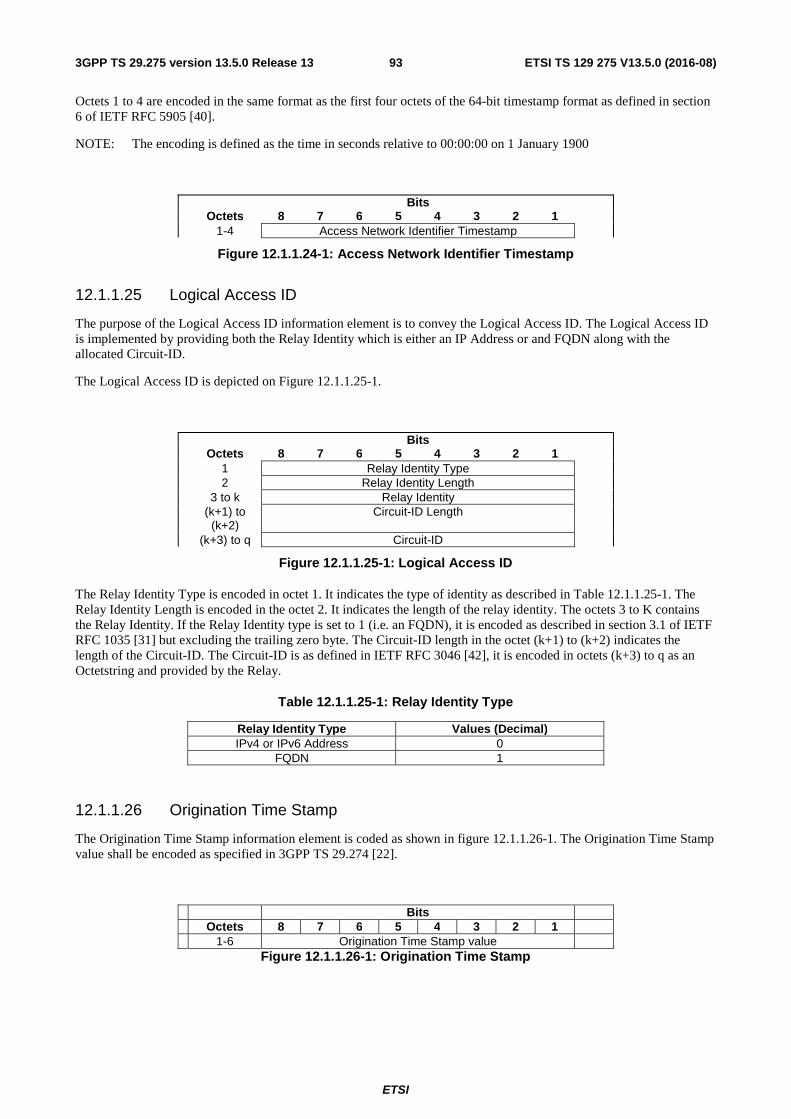
ETSI
ETSI TS 129 275 V13.5.0 (2016-08)933GPP TS 29.275 version 13.5.0 Release 13
Octets 1 to 4 are encoded in the same format as the first four octets of the 64-bit timestamp format as defined in section 6 of IETF RFC 5905 [40].
NOTE: The encoding is defined as the time in seconds relative to 00:00:00 on 1 January 1900
Bits Octets 8 7 6 5 4 3 2 1 1-4 Access Network Identifier Timestamp
Figure 12.1.1.24-1: Access Network Identifier Timestamp
12.1.1.25 Logical Access ID
The purpose of the Logical Access ID information element is to convey the Logical Access ID. The Logical Access ID is implemented by providing both the Relay Identity which is either an IP Address or and FQDN along with the allocated Circuit-ID.
The Logical Access ID is depicted on Figure 12.1.1.25-1.
Bits Octets 8 7 6 5 4 3 2 1 1 Relay Identity Type 2 Relay Identity Length 3 to k Relay Identity (k+1) to
(k+2) Circuit-ID Length
(k+3) to q Circuit-ID
Figure 12.1.1.25-1: Logical Access ID
The Relay Identity Type is encoded in octet 1. It indicates the type of identity as described in Table 12.1.1.25-1. The Relay Identity Length is encoded in the octet 2. It indicates the length of the relay identity. The octets 3 to K contains the Relay Identity. If the Relay Identity type is set to 1 (i.e. an FQDN), it is encoded as described in section 3.1 of IETF RFC 1035 [31] but excluding the trailing zero byte. The Circuit-ID length in the octet (k+1) to (k+2) indicates the length of the Circuit-ID. The Circuit-ID is as defined in IETF RFC 3046 [42], it is encoded in octets (k+3) to q as an Octetstring and provided by the Relay.
Table 12.1.1.25-1: Relay Identity Type
Relay Identity Type Values (Decimal) IPv4 or IPv6 Address 0
FQDN 1
12.1.1.26 Origination Time Stamp
The Origination Time Stamp information element is coded as shown in figure 12.1.1.26-1. The Origination Time Stamp value shall be encoded as specified in 3GPP TS 29.274 [22].
Bits Octets 8 7 6 5 4 3 2 1 1-6 Origination Time Stamp value
Figure 12.1.1.26-1: Origination Time Stamp
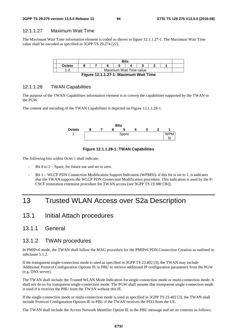
ETSI
ETSI TS 129 275 V13.5.0 (2016-08)943GPP TS 29.275 version 13.5.0 Release 13
12.1.1.27 Maximum Wait Time
The Maximum Wait Time information element is coded as shown in figure 12.1.1.27-1. The Maximum Wait Time value shall be encoded as specified in 3GPP TS 29.274 [22].
Bits Octets 8 7 6 5 4 3 2 1 1-2 Maximum Wait Time value
Figure 12.1.1.27-1: Maximum Wait Time
12.1.1.28 TWAN Capabilities
The purpose of the TWAN Capabilities information element is to convey the capabilities supported by the TWAN to the PGW.
The content and encoding of the TWAN Capabilities is depicted on Figure 12.1.1.28-1.
Bits Octets 8 7 6 5 4 3 2 1
1 Spare WPMSI
Figure 12.1.1.28-1: TWAN Capabilities
The following bits within Octet 1 shall indicate:
- Bit 8 to 2 – Spare, for future use and set to zero.
- Bit 1 – WLCP PDN Connection Modification Support Indication (WPMSI): if this bit is set to 1, it indicates that the TWAN supports the WLCP PDN Connection Modification procedure. This indication is used by the P-CSCF restoration extension procedure for TWAN access (see 3GPP TS 23.380 [36]).
13 Trusted WLAN Access over S2a Description
13.1 Initial Attach procedures
13.1.1 General
13.1.2 TWAN procedures
In PMIPv6 mode, the TWAN shall follow the MAG procedure for the PMIPv6 PDN Connection Creation as outlined in subclause 5.1.2.
If the transparent single-connection mode is used as specified in 3GPP TS 23.402 [3], the TWAN may include Additional Protocol Configuration Options IE in PBU to retrieve additional IP configuration parameters from the PGW (e.g. DNS server).
The TWAN shall include the Trusted WLAN Mode Indication for single-connection mode or multi-connection mode. It shall not do so for transparent single-connection mode. The PGW shall assume that transparent single-connection mode is used if it receives the PBU from the TWAN without this IE.
If the single-connection mode or multi-connection mode is used as specified in 3GPP TS 23.402 [3], the TWAN shall include Protocol Configuration Options IE in PBU if the TWAN receives the PCO from the UE.
The TWAN shall include the Access Network Identifier Option IE in the PBU message and set its contents as follows:
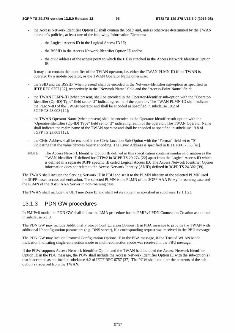
ETSI
ETSI TS 129 275 V13.5.0 (2016-08)953GPP TS 29.275 version 13.5.0 Release 13
- the Access Network Identifier Option IE shall contain the SSID and, unless otherwise determined by the TWAN operator"s policies, at least one of the following Information Elements:
- the Logical Access ID in the Logical Access ID IE;
- the BSSID in the Access Network Identifier Option IE and/or
- the civic address of the access point to which the UE is attached in the Access Network Identifier Option IE.
- It may also contain the identifier of the TWAN operator, i.e. either the TWAN PLMN-ID if the TWAN is operated by a mobile operator, or the TWAN Operator Name otherwise;
- the SSID and the BSSID (when present) shall be encoded in the Network-Identifier sub-option as specified in IETF RFC 6757 [37], respectively in the "Network Name" field and the "Access-Point Name" field;
- the TWAN PLMN-ID (when present) shall be encoded in the Operator-Identifier sub-option with the "Operator-Identifier (Op-ID) Type" field set to "2" indicating realm of the operator. The TWAN PLMN-ID shall indicate the PLMN-ID of the TWAN operator and shall be encoded as specified in subclause 19.2 of 3GPP TS 23.003 [12];
- the TWAN Operator Name (when present) shall be encoded in the Operator-Identifier sub-option with the "Operator-Identifier (Op-ID) Type" field set to "2" indicating realm of the operator. The TWAN Operator Name shall indicate the realm name of the TWAN operator and shall be encoded as specified in subclause 19.8 of 3GPP TS 23.003 [12].
- the Civic Address shall be encoded in the Civic Location Sub-Option with the "Format" field set to "0" indicating that the value denotes binary encoding. The Civic Address is specified in IETF RFC 7563 [41].
NOTE: The Access Network Identifier Option IE defined in this specification contains similar information as the TWAN Identifier IE defined for GTPv2 in 3GPP TS 29.274 [22] apart from the Logical Access ID which is defined in a separate 3GPP specific IE called Logical Access ID. The Access Network Identifier Option information does not relate to the Access Network Identity (ANID) defined in 3GPP TS 24.302 [39].
The TWAN shall include the Serving Network IE in PBU and set it to the PLMN identity of the selected PLMN used for 3GPP-based access authentication. The selected PLMN is the PLMN of the 3GPP AAA Proxy in roaming case and the PLMN of the 3GPP AAA Server in non-roaming case.
The TWAN shall include the UE Time Zone IE and shall set its content as specified in subclause 12.1.1.23.
13.1.3 PDN GW procedures
In PMIPv6 mode, the PDN GW shall follow the LMA procedure for the PMIPv6 PDN Connection Creation as outlined in subclause 5.1.3.
The PDN GW may include Additional Protocol Configuration Options IE in PBA message to provide the TWAN with additional IP configuration parameters (e.g. DNS server), if a corresponding request was received in the PBU message.
The PDN GW may include Protocol Configuration Options IE in the PBA message, if the Trusted WLAN Mode Indication indicating single-connection mode or multi-connection mode was received in the PBU message.
If the PGW supports Access Network Identifier Option and the TWAN had included the Access Network Identifier Option IE in the PBU message, the PGW shall include the Access Network Identifier Option IE with the sub-option(s) that it accepted as outlined in subclause 4.2 of IETF RFC 6757 [37]. The PGW shall not alter the contents of the sub-option(s) received from the TWAN.
ETSI
ETSI TS 129 275 V13.5.0 (2016-08)963GPP TS 29.275 version 13.5.0 Release 13
13.2 TWAN Initiated PDN Connection Lifetime Extension procedures
13.2.1 General
13.2.2 TWAN procedures
In PMIPv6 mode, the TWAN shall follow the MAG procedure for the PMIPv6 PDN Connection Lifetime Extension as outlined in subclause 5.2.2.
13.2.3 PDN GW procedures
In PMIPv6 mode, the PDN GW shall follow the LMA procedure for the PMIPv6 PDN Connection Lifetime Extension as outlined in subclause 5.2.3.
13.3 UE / TWAN Initiated Detach and UE/TWAN Requested PDN Disconnection procedures
13.3.1 General
13.3.2 TWAN procedures
In PMIPv6 mode, the TWAN shall follow the MAG procedure for the PMIPv6 MAG Initiated PDN Connection Deletion as outlined in subclause 5.4.2 for Detach/PDN Disconnection procedure.
The TWAN shall include the Access Network Identifier Option IE and the Access Network Identifier Timestamp IE and shall set its content as specified in subclause 13.1.2 and 12.1.1.24 respectively.
The TWAN shall include the UE Time Zone IE and shall set its content as specified in subclause 12.1.1.23.
13.3.3 PDN GW procedures
In PMIPv6 mode, the PDN GW shall follow the LMA procedure for the PMIPv6 MAG Initiated PDN Connection Deletion as outlined in subclause 5.4.3.
If the PGW supports Access Network Identifier Option and the TWAN had included the Access Network Identifier Option IE in the PBU message, the PGW shall include the Access Network Identifier Option IE with the sub-option(s) that it accepted as outlined in subclause 4.2 of IETF RFC 6757 [37]. The PGW shall not alter the contents of the sub-option(s) received from the TWAN.
13.4 HSS / AAA Initiated Detach procedures
13.4.1 General
The HSS/AAA may initiate a detach procedure resulting in a PMIPv6 De-Registration.
13.4.2 TWAN procedures
In PMIPv6 mode, the TWAN shall follow the MAG procedure for the PMIPv6 MAG Initiated PDN Connection Deletion as outlined in subclause 5.4.2.
The TWAN shall include the Access Network Identifier Option IE and the Access Network Identifier Timestamp IE and shall set its content as specified in subclause 13.1.2 and 12.1.1.24 respectively.
ETSI
ETSI TS 129 275 V13.5.0 (2016-08)973GPP TS 29.275 version 13.5.0 Release 13
The TWAN shall include the UE Time Zone IE and shall set its content as specified in subclause 12.1.1.23.
13.4.3 PDN GW procedures
In PMIPv6 mode, the PDN GW shall follow the LMA procedure for the PMIPv6 MAG Initiated PDN Connection Deletion as outlined in subclause 5.4.3.
If the PGW supports Access Network Identifier Option and the TWAN had included the Access Network Identifier Option IE in the PBU message, the PGW shall include the Access Network Identifier Option IE with the sub-option(s) that it accepted as outlined in subclause 4.2 of IETF RFC 6757 [37]. The PGW shall not alter the contents of the sub-option(s) received from the TWAN.
13.5 PDN GW Initiated Resource Allocation Deactivation procedures
13.5.1 General
13.5.2 TWAN procedures
In PMIPv6 mode, the Trusted Non-3GPP Access shall follow the MAG procedure for the PMIPv6 LMA Initiated PDN Connection Deletion as outlined in subclause 5.5.2.
The TWAN shall include the Access Network Identifier Option IE and the Access Network Identifier Timestamp IE and shall set its content as specified in subclause 13.1.2 and 12.1.1.24 respectively.
The TWAN shall include the UE Time Zone IE and shall set its content as specified in subclause 12.1.1.23.
13.5.3 PDN GW procedures
In PMIPv6 mode, the PDN GW shall follow the LMA procedure for the PMIPv6 LMA Initiated PDN Connection Deletion as outlined in subclause 5.5.3.
The PGW shall include the 3GPP Specific PMIPv6 error code IE and set it to the cause "Reactivation requested" when the PGW initiates the PDN GW Initiated Resource Allocation Deactivation procedure as part of the P-CSCF restoration procedure over WLAN access, as specified in 3GPP TS 23.380 [36].
13.6 3GPP Access to TWAN with PMIPv6 on S2a Handover procedures without optimization
13.6.1 General
This procedure shall apply for a TWAN access using single-connection mode or multi-connection mode.
13.6.2 TWAN procedures
In PMIPv6 mode, the TWAN shall follow the MAG procedure for the PMIPv6 PDN Connection Handover as outlined in subclause 5.3.2.
The TWAN shall include in the PBU message:
- the Protocol Configuration Options IE if the TWAN received the PCO from the UE.
- the Access Network Identifier Option IE and set its content as specified in subclause 13.1.2.
- the Serving Network IE and set it to the PLMN identity of the selected PLMN used for 3GPP-based access authentication. The selected PLMN is the PLMN of the 3GPP AAA Proxy in roaming case and the PLMN of the 3GPP AAA Server in non-roaming case.
ETSI
ETSI TS 129 275 V13.5.0 (2016-08)983GPP TS 29.275 version 13.5.0 Release 13
- the Trusted WLAN Mode Indication for single-connection mode or multi-connection mode.
The TWAN shall include the UE Time Zone IE and shall set its content as specified in subclause 12.1.1.23.
The TWAN shall include the TWAN Capabilities IE in the PBU message and set the WLCP PDN Connection Modification Support Indication flag to 1 if the TWAN supports this procedure.
13.6.3 PDN GW procedures
In PMIPv6 mode, the PDN GW shall follow the LMA procedure for the PMIPv6 PDN Connection Handover as outlined in subclause 5.3.3.
If the PGW supports Access Network Identifier Option and the TWAN had included the Access Network Identifier Option IE in the PBU message, the PGW shall include the Access Network Identifier Option IE with the sub-option(s) that it accepted as outlined in subclause 4.2 of IETF RFC 6757 [37]. The PGW shall not alter the contents of the sub-option(s) received from the TWAN.
The PDN GW may include Protocol Configuration Options IE in the PBA message.
13.7 UE Initiated Connectivity to Additional PDN procedures
13.7.1 General
This procedure only applies for a TWAN access using the multiconnection mode.
13.7.2 TWAN procedures
In PMIPv6 mode, the TWAN shall follow the MAG procedure for the PMIPv6 PDN Connection Creation as outlined in subclause 5.1.2, or the MAG procedure for the PMIPv6 PDN Connection Handover as outlined in subclause 5.3.2.
The TWAN shall include in the PBU message:
- the Protocol Configuration Options IE if the TWAN received the PCO from the UE;
- the Access Network Identifier Option IE and the UE timezone IE and set their contents as specified in subclause 13.1.2;
- the Serving Network IE and set it to the PLMN identity of the selected PLMN used for 3GPP-based access authentication. The selected PLMN is the PLMN of the 3GPP AAA Proxy in roaming case and the PLMN of the 3GPP AAA Server in non-roaming case;
- the Trusted WLAN Mode Indication for multi-connection mode;
- the TWAN Capabilities IE and set the WLCP PDN Connection Modification Support Indication flag to 1 if the TWAN supports this procedure.
13.7.3 PDN GW procedures
In PMIPv6 mode, the PDN GW shall follow the LMA procedure for the PMIPv6 PDN Connection Creation as outlined in subclause 5.1.3, or the LMA procedure for the PMIPv6 PDN Connection Handover as outlined in subclause 5.3.3.
If the PGW supports Access Network Identifier Option and the TWAN had included the Access Network Identifier Option IE in the PBU message, the PGW shall include the Access Network Identifier Option IE with the sub-option(s) that it accepted as outlined in subclause 4.2 of IETF RFC 6757 [37]. The PGW shall not alter the contents of the sub-option(s) received from the TWAN.
The PDN GW may include the Protocol Configuration Options IE in the PBA message.
ETSI
ETSI TS 129 275 V13.5.0 (2016-08)993GPP TS 29.275 version 13.5.0 Release 13
14 Proxy Mobile IPv6 EPC Restoration Procedure
14.1 PGW triggered SGW restoration procedure
14.1.1 General
The PGW triggered SGW restoration procedure is specified in 3GPP TS 23.007 [13]. The Proxy Mobile IPv6 LMA Initiated Update Notification procedure specified in subclause 5.11 is used to initiate the PGW triggered SGW restoration procedure.
14.1.2 Serving GW procedures
The Serving GW shall follow the PGW triggered SGW restoration procedure as specified in subclause 27.2.3.3 of 3GPP TS 23.007 [13]. When receiving the Update Notification message with notification reason "PGW Downlink Trigger Notification", the Serving GW shall response with an Update Notification Acknowledgement message specified as the MAG procedure in subclause 5.11.
14.1.3 PDN GW procedures
The PDN GW shall follow the PGW triggered SGW restoration procedure as specified in subclause 27.2.3.4 and 20.2.7.1 of 3GPP TS 23.007 [13]. When sending the Update Notification message, the PDN GW shall follow the LMA procedure specified in subclause 5.11 as follows:
1. The notification reason shall be set to "PGW Downlink Trigger Notification".
Editor's Note: The Notification reason "PGW Downlink Trigger Notification " needs to be registered in IANA.
2. If the MME/S4-SGSN identifier was received in the last Create Session Request or Modify Bearer Request message as specified in 3GPP TS 23.007 [13], the MME/SGSN Identifier mobility option shall contain the stored MME/S4-SGSN identifier.
3. If the restoration procedure is caused by S5 path failure as specified in subclause 20.2.7.1 of 3GPP TS 23.007 [13], the Update Notification Message shall contain the PDN GW IP Address and GRE key option which shall contain the PGW IP address and uplink GRE key for control plane for the PDN connection.
14.2 Update PDP context/Bearer at P-CSCF failure
14.2.1 General
The update PDP context/Bearer at P-CSCF failure procedure is specified in subclause 5.1 of 3GPP TS 23.380 [36]. The Proxy Mobile IPv6 LMA Initiated Update Notification procedure specified in subclause 5.11 is used to inform the SGW at P-CSCF failure.
This procedure is also used from the PGW to the TWAN or ePDG to provide the UE with a list of available P-CSCF addresses as part of the P-CSCF restoration extension procedure for TWAN access and untrusted WLAN access (3GPP TS 23.380 [36]).
14.2.2 PDN GW procedures
The PDN GW shall follow the update PDP context/Bearer at P-CSCF failure procedure as specified in subclause 5.1 of 3GPP TS 23.380 [36], or the P-CSCF restoration extension procedure for TWAN access and untrusted WLAN access as specified in 3GPP TS 23.380 [36]. When sending the Update Notification message, the PDN GW shall follow the LMA procedure specified in subclause 5.11 as follows:
1. The notification reason shall be set to "PGW-TRIGGERED-PCSCF-RESTORATION-PCO".
ETSI
ETSI TS 129 275 V13.5.0 (2016-08)1003GPP TS 29.275 version 13.5.0 Release 13
2. The Service Selection Mobility Option shall be set to the corresponding APN to which the UE PDN connection is attached
3. The PDN connection ID Mobility Option shall contain the PDN connection ID stored in the BCE if multiple PDN connection to a given APN is supported.
4. The PCO Mobility Option (for S5/S8 and S2a) or the APCO Mobility Option (for S2b) shall contain a list of available P-CSCF addresses.
14.2.3 Serving GW, TWAN and ePDG procedures
The Serving GW shall follow the update PDP context/Bearer at P-CSCF failure procedure as specified in subclause 5.1 of 3GPP TS 23.380 [36]. When receiving the Update Notification message with notification reason "PGW triggered P-CSCF restoration using PCO", the Serving GW shall respond with an Update Notification Acknowledgement message specified as the MAG procedure in subclause 5.11.
The TWAN and ePDG shall follow the P-CSCF restoration extension procedure for TWAN access and untrusted WLAN access as specified in 3GPP TS 23.380 [36]. When receiving the Update Notification message with notification reason "PGW triggered P-CSCF restoration using PCO", the TWAN or ePDG shall respond with an Update Notification Acknowledgement message specified as the MAG procedure in subclause 5.11.
14.3 Inform UE about P-CSCF failure
14.3.1 General
The Inform UE about P-CSCF failure procedure is specified in subclause 5.2 of 3GPP TS 23.380 [36]. The Proxy Mobile IPv6 LMA Initiated Update Notification procedure specified in subclause 5.11 is used to inform the SGW at P-CSCF failure.
14.3.2 PDN GW procedures
The PDN GW shall follow the inform UE about P-CSCF failure procedure as specified in subclause 5.2 of 3GPP TS 23.380 [36]. When sending the Update Notification message, the PDN GW shall follow the LMA procedure specified in subclause 5.11 as follows:
1. The notification reason shall be set to "PGW-TRIGGERED-PCSCF-RESTORATION-DHCP".
2. The Service Selection Mobility Option shall be set to the corresponding APN to which the UE PDN connection is attached
3. The PDN connection ID Mobility Option shall contain the PDN connection ID stored in the BCE if multiple PDN connection to a given APN is supported.
4. The PCO Mobility Option shall contain an indicator that there is P-CSCF failure.
14.3.3 Serving GW procedures
The Serving GW shall follow the inform UE about P-CSCF failure procedure as specified in subclause 5.2 of 3GPP TS 23.380 [36]. When receiving the Update Notification message with notification reason "PGW triggered P-CSCF restoration using DHCP", the Serving GW shall response with an Update Notification Acknowledgement message specified as the MAG procedure in subclause 5.11.
ETSI
ETSI TS 129 275 V13.5.0 (2016-08)1013GPP TS 29.275 version 13.5.0 Release 13
15 Proxy Mobile IPv6 End Marker Notification Procedure
15.1 General Proxy Mobile IPv6 End Marker notification procedure is specified in subclause 5.7.1 and 5.7.2 of 3GPP TS 23.402 [3]. The Proxy Mobile IPv6 LMA Initiated Update Notification procedure specified in subclause 5.11 is used to initiate the Proxy Mobile IPv6 End Marker Notification Procedure.
15.2 Serving GW procedures The Serving GW shall follow the Proxy Mobile IPv6 End Marker notification procedure as specified in subclause 5.7.1 and 5.7.2 of 3GPP TS 23.402 [3]. When receiving the Update Notification message with notification reason "VENDOR-SPECIFIC-REASON" and End Marker Notification mobility option and the serving GW has downlink user plane established, the Serving GW shall generate End Marker as specified in subclause 5.7.1 and 5.7.2 of 3GPP TS 23.402 [3]. When receiving the Update Notification message, the Serving GW shall follow the MAG procedure specified in subclause 5.11.
15.3 PDN GW procedures The PDN GW shall follow Proxy Mobile IPv6 End Marker notification procedure as specified in subclause 5.7.1 and 5.7.2 of 3GPP TS 23.402 [3]. When sending the Update Notification message, the PDN GW shall follow the LMA procedure specified in subclause 5.11 as follows:
1. The PDN GW shall set the notification reason to "VENDOR-SPECIFIC-REASON" as specified in IETF RFC 7077 [35].
2. The PDN GW shall include End Marker Notification mobility option.
3. The PDN GW shall set the Acknowledge (A) flag to "0", thereby not requesting an acknowledgement message from the Serving GW.
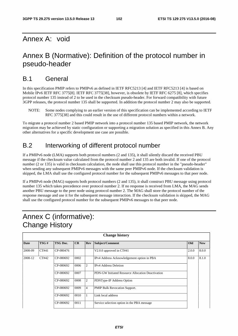
ETSI
ETSI TS 129 275 V13.5.0 (2016-08)1023GPP TS 29.275 version 13.5.0 Release 13
Annex A: void
Annex B (Normative): Definition of the protocol number in pseudo-header
B.1 General In this specification PMIP refers to PMIPv6 as defined in IETF RFC5213 [4] and IETF RFC5213 [4] is based on Mobile IPv6 IETF RFC 3775[8]. IETF RFC 3775[38], however, is obsolete by IETF RFC 6275 [8], which specifies protocol number 135 instead of 2 to be used in the checksum pseudo-header. For forward compatibility with future 3GPP releases, the protocol number 135 shall be supported. In addition the protocol number 2 may also be supported.
NOTE: Some nodes complying to an earlier version of this specification can be implemented according to IETF RFC 3775[38] and this could result in the use of different protocol numbers within a network.
To migrate a protocol number 2 based PMIP network into a protocol number 135 based PMIP network, the network migration may be achieved by static configuration or supporting a migration solution as specified in this Annex B. Any other alternatives for a specific development use case are possible.
B.2 Interworking of different protocol number If a PMIPv6 node (LMA) supports both protocol numbers (2 and 135), it shall silently discard the received PBU message if the checksum value calculated from the protocol number 2 and 135 are both invalid. If one of the protocol number (2 or 135) is valid in checksum calculation, the node shall use this protocol number in the "pseudo-header" when sending any subsequent PMIPv6 messages with the same peer PMIPv6 node. If the checksum validation is skipped, the LMA shall use the configured protocol number for the subsequent PMIPv6 messages to that peer node.
If a PMIPv6 node (MAG) supports both protocol numbers (2 and 135), it shall construct PBU message using protocol number 135 which takes precedence over protocol number 2. If no response is received from LMA, the MAG sends another PBU message to the peer node using protocol number 2. The MAG shall store the protocol number of the response message and use it for the subsequent message interaction. If the checksum validation is skipped, the MAG shall use the configured protocol number for the subsequent PMIPv6 messages to that peer node.
Annex C (informative): Change History
Change history
Date TSG # TSG Doc. CR Rev Subject/Comment Old New
2008-09 CT#41 CP-080476 V2.0.0 approved in CT#41 2.0.0 8.0.0
2008-12 CT#42 CP-080692 0002 IPv4 Address Acknowledgement option in PBA 8.0.0 8.1.0
CP-080692 0006 2 IPv4 Address Deletion
CP-080692 0007 PDN-GW Initiated Resource Allocation Deactivation
CP-080692 0008 2 PDNType-IP Address Option
CP-080692 0009 4 PMIP Bulk Revocation Support.
CP-080692 0010 1 Link local address
CP-080692 0011 Service selection option in the PBA message
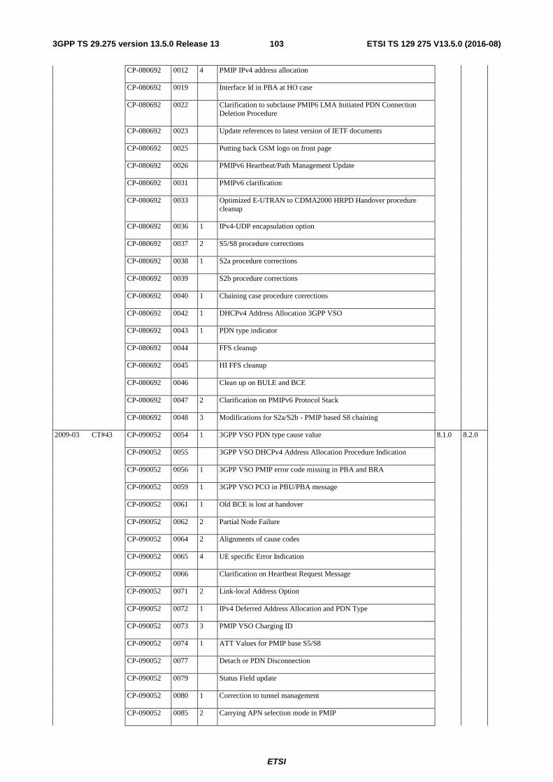
ETSI
ETSI TS 129 275 V13.5.0 (2016-08)1033GPP TS 29.275 version 13.5.0 Release 13
CP-080692 0012 4 PMIP IPv4 address allocation
CP-080692 0019 Interface Id in PBA at HO case
CP-080692 0022 Clarification to subclause PMIP6 LMA Initiated PDN Connection Deletion Procedure
CP-080692 0023 Update references to latest version of IETF documents
CP-080692 0025 Putting back GSM logo on front page
CP-080692 0026 PMIPv6 Heartbeat/Path Management Update
CP-080692 0031 PMIPv6 clarification
CP-080692 0033 Optimized E-UTRAN to CDMA2000 HRPD Handover procedure cleanup
CP-080692 0036 1 IPv4-UDP encapsulation option
CP-080692 0037 2 S5/S8 procedure corrections
CP-080692 0038 1 S2a procedure corrections
CP-080692 0039 S2b procedure corrections
CP-080692 0040 1 Chaining case procedure corrections
CP-080692 0042 1 DHCPv4 Address Allocation 3GPP VSO
CP-080692 0043 1 PDN type indicator
CP-080692 0044 FFS cleanup
CP-080692 0045 HI FFS cleanup
CP-080692 0046 Clean up on BULE and BCE
CP-080692 0047 2 Clarification on PMIPv6 Protocol Stack
CP-080692 0048 3 Modifications for S2a/S2b - PMIP based S8 chaining
2009-03 CT#43 CP-090052 0054 1 3GPP VSO PDN type cause value 8.1.0 8.2.0
CP-090052 0055 3GPP VSO DHCPv4 Address Allocation Procedure Indication
CP-090052 0056 1 3GPP VSO PMIP error code missing in PBA and BRA
CP-090052 0059 1 3GPP VSO PCO in PBU/PBA message
CP-090052 0061 1 Old BCE is lost at handover
CP-090052 0062 2 Partial Node Failure
CP-090052 0064 2 Alignments of cause codes
CP-090052 0065 4 UE specific Error Indication
CP-090052 0066 Clarification on Heartbeat Request Message
CP-090052 0071 2 Link-local Address Option
CP-090052 0072 1 IPv4 Deferred Address Allocation and PDN Type
CP-090052 0073 3 PMIP VSO Charging ID
CP-090052 0074 1 ATT Values for PMIP base S5/S8
CP-090052 0077 Detach or PDN Disconnection
CP-090052 0079 Status Field update
CP-090052 0080 1 Correction to tunnel management
CP-090052 0085 2 Carrying APN selection mode in PMIP
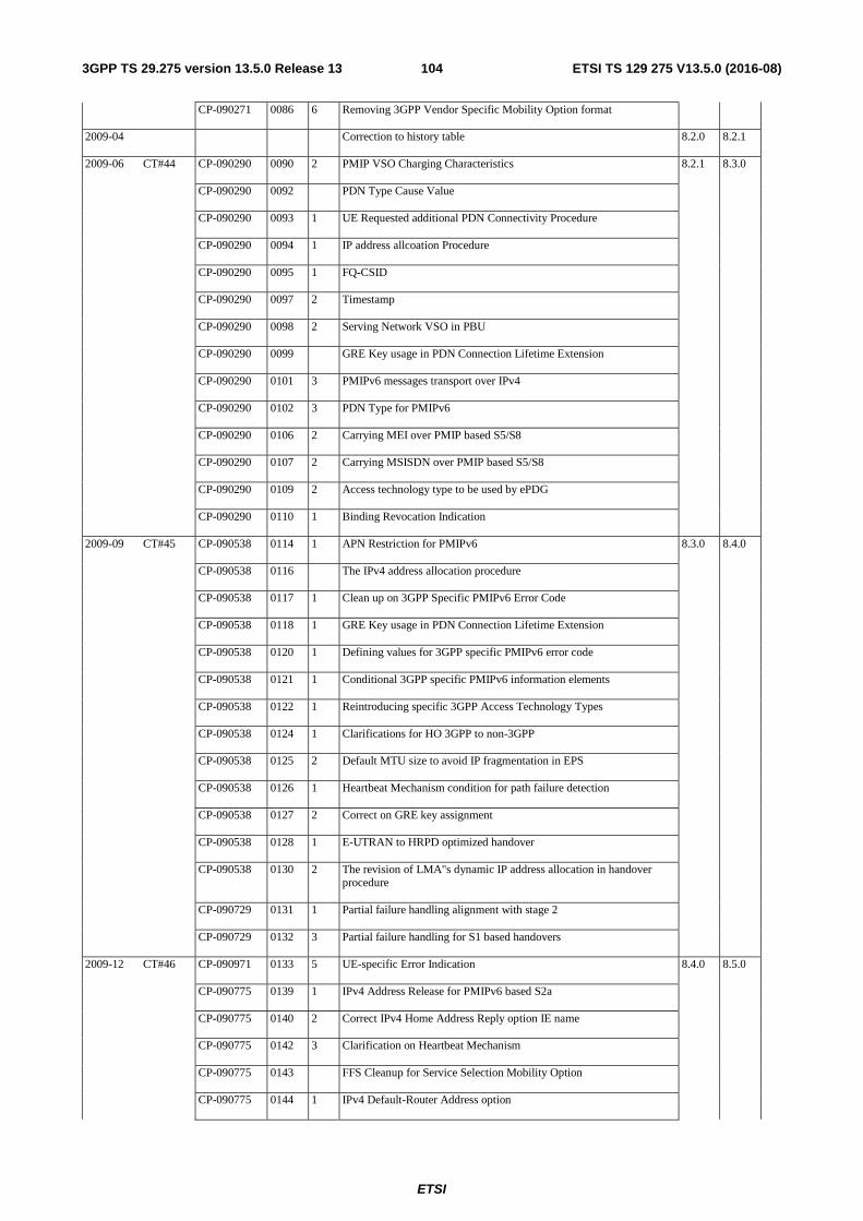
ETSI
ETSI TS 129 275 V13.5.0 (2016-08)1043GPP TS 29.275 version 13.5.0 Release 13
CP-090271 0086 6 Removing 3GPP Vendor Specific Mobility Option format
2009-04 Correction to history table 8.2.0 8.2.1
2009-06 CT#44 CP-090290 0090 2 PMIP VSO Charging Characteristics 8.2.1 8.3.0
CP-090290 0092 PDN Type Cause Value
CP-090290 0093 1 UE Requested additional PDN Connectivity Procedure
CP-090290 0094 1 IP address allcoation Procedure
CP-090290 0095 1 FQ-CSID
CP-090290 0097 2 Timestamp
CP-090290 0098 2 Serving Network VSO in PBU
CP-090290 0099 GRE Key usage in PDN Connection Lifetime Extension
CP-090290 0101 3 PMIPv6 messages transport over IPv4
CP-090290 0102 3 PDN Type for PMIPv6
CP-090290 0106 2 Carrying MEI over PMIP based S5/S8
CP-090290 0107 2 Carrying MSISDN over PMIP based S5/S8
CP-090290 0109 2 Access technology type to be used by ePDG
CP-090290 0110 1 Binding Revocation Indication
2009-09 CT#45 CP-090538 0114 1 APN Restriction for PMIPv6 8.3.0 8.4.0
CP-090538 0116 The IPv4 address allocation procedure
CP-090538 0117 1 Clean up on 3GPP Specific PMIPv6 Error Code
CP-090538 0118 1 GRE Key usage in PDN Connection Lifetime Extension
CP-090538 0120 1 Defining values for 3GPP specific PMIPv6 error code
CP-090538 0121 1 Conditional 3GPP specific PMIPv6 information elements
CP-090538 0122 1 Reintroducing specific 3GPP Access Technology Types
CP-090538 0124 1 Clarifications for HO 3GPP to non-3GPP
CP-090538 0125 2 Default MTU size to avoid IP fragmentation in EPS
CP-090538 0126 1 Heartbeat Mechanism condition for path failure detection
CP-090538 0127 2 Correct on GRE key assignment
CP-090538 0128 1 E-UTRAN to HRPD optimized handover
CP-090538 0130 2 The revision of LMA"s dynamic IP address allocation in handover procedure
CP-090729 0131 1 Partial failure handling alignment with stage 2
CP-090729 0132 3 Partial failure handling for S1 based handovers
2009-12 CT#46 CP-090971 0133 5 UE-specific Error Indication 8.4.0 8.5.0
CP-090775 0139 1 IPv4 Address Release for PMIPv6 based S2a
CP-090775 0140 2 Correct IPv4 Home Address Reply option IE name
CP-090775 0142 3 Clarification on Heartbeat Mechanism
CP-090775 0143 FFS Cleanup for Service Selection Mobility Option
CP-090775 0144 1 IPv4 Default-Router Address option
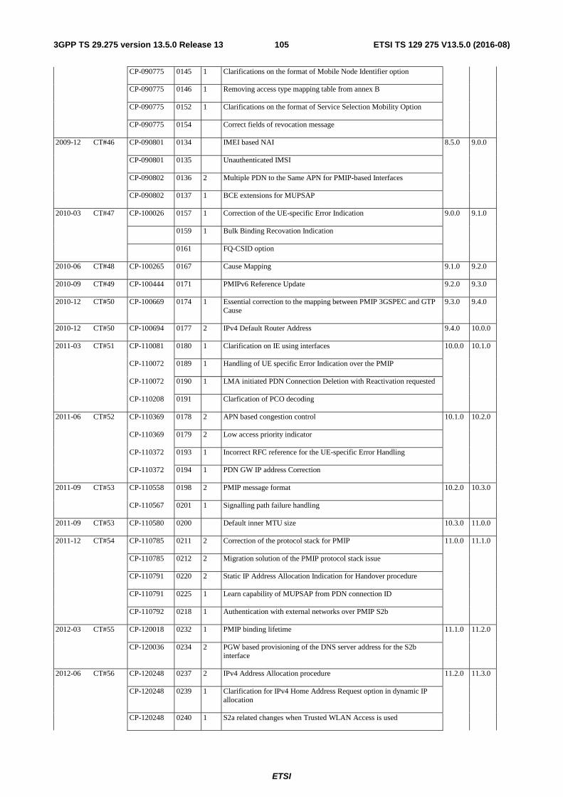
ETSI
ETSI TS 129 275 V13.5.0 (2016-08)1053GPP TS 29.275 version 13.5.0 Release 13
CP-090775 0145 1 Clarifications on the format of Mobile Node Identifier option
CP-090775 0146 1 Removing access type mapping table from annex B
CP-090775 0152 1 Clarifications on the format of Service Selection Mobility Option
CP-090775 0154 Correct fields of revocation message
2009-12 CT#46 CP-090801 0134 IMEI based NAI 8.5.0 9.0.0
CP-090801 0135 Unauthenticated IMSI
CP-090802 0136 2 Multiple PDN to the Same APN for PMIP-based Interfaces
CP-090802 0137 1 BCE extensions for MUPSAP
2010-03 CT#47 CP-100026 0157 1 Correction of the UE-specific Error Indication 9.0.0 9.1.0
0159 1 Bulk Binding Recovation Indication
0161 FQ-CSID option
2010-06 CT#48 CP-100265 0167 Cause Mapping 9.1.0 9.2.0
2010-09 CT#49 CP-100444 0171 PMIPv6 Reference Update 9.2.0 9.3.0
2010-12 CT#50 CP-100669 0174 1 Essential correction to the mapping between PMIP 3GSPEC and GTP Cause
9.3.0 9.4.0
2010-12 CT#50 CP-100694 0177 2 IPv4 Default Router Address 9.4.0 10.0.0
2011-03 CT#51 CP-110081 0180 1 Clarification on IE using interfaces 10.0.0 10.1.0
CP-110072 0189 1 Handling of UE specific Error Indication over the PMIP
CP-110072 0190 1 LMA initiated PDN Connection Deletion with Reactivation requested
CP-110208 0191 Clarfication of PCO decoding
2011-06 CT#52 CP-110369 0178 2 APN based congestion control 10.1.0 10.2.0
CP-110369 0179 2 Low access priority indicator
CP-110372 0193 1 Incorrect RFC reference for the UE-specific Error Handling
CP-110372 0194 1 PDN GW IP address Correction
2011-09 CT#53 CP-110558 0198 2 PMIP message format 10.2.0 10.3.0
CP-110567 0201 1 Signalling path failure handling
2011-09 CT#53 CP-110580 0200 Default inner MTU size 10.3.0 11.0.0
2011-12 CT#54 CP-110785 0211 2 Correction of the protocol stack for PMIP 11.0.0 11.1.0
CP-110785 0212 2 Migration solution of the PMIP protocol stack issue
CP-110791 0220 2 Static IP Address Allocation Indication for Handover procedure
CP-110791 0225 1 Learn capability of MUPSAP from PDN connection ID
CP-110792 0218 1 Authentication with external networks over PMIP S2b
2012-03 CT#55 CP-120018 0232 1 PMIP binding lifetime 11.1.0 11.2.0
CP-120036 0234 2 PGW based provisioning of the DNS server address for the S2b interface
2012-06 CT#56 CP-120248 0237 2 IPv4 Address Allocation procedure 11.2.0 11.3.0
CP-120248 0239 1 Clarification for IPv4 Home Address Request option in dynamic IP allocation
CP-120248 0240 1 S2a related changes when Trusted WLAN Access is used
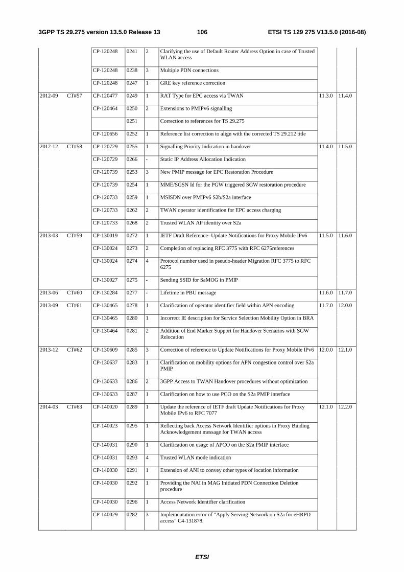
ETSI
ETSI TS 129 275 V13.5.0 (2016-08)1063GPP TS 29.275 version 13.5.0 Release 13
CP-120248 0241 2 Clarifying the use of Default Router Address Option in case of Trusted WLAN access
CP-120248 0238 3 Multiple PDN connections
CP-120248 0247 1 GRE key reference correction
2012-09 CT#57 CP-120477 0249 1 RAT Type for EPC access via TWAN 11.3.0 11.4.0
CP-120464 0250 2 Extensions to PMIPv6 signalling
0251 Correction to references for TS 29.275
CP-120656 0252 1 Reference list correction to align with the corrected TS 29.212 title
2012-12 CT#58 CP-120729 0255 1 Signalling Priority Indication in handover 11.4.0 11.5.0
CP-120729 0266 - Static IP Address Allocation Indication
CP-120739 0253 3 New PMIP message for EPC Restoration Procedure
CP-120739 0254 1 MME/SGSN Id for the PGW triggered SGW restoration procedure
CP-120733 0259 1 MSISDN over PMIPv6 S2b/S2a interface
CP-120733 0262 2 TWAN operator identification for EPC access charging
CP-120733 0268 2 Trusted WLAN AP identity over S2a
2013-03 CT#59 CP-130019 0272 1 IETF Draft Reference- Update Notifications for Proxy Mobile IPv6 11.5.0 11.6.0
CP-130024 0273 2 Completion of replacing RFC 3775 with RFC 6275references
CP-130024 0274 4 Protocol number used in pseudo-header Migration RFC 3775 to RFC 6275
CP-130027 0275 - Sending SSID for SaMOG in PMIP
2013-06 CT#60 CP-130284 0277 - Lifetime in PBU message 11.6.0 11.7.0
2013-09 CT#61 CP-130465 0278 1 Clarification of operator identifier field within APN encoding 11.7.0 12.0.0
CP-130465 0280 1 Incorrect IE description for Service Selection Mobility Option in BRA
CP-130464 0281 2 Addition of End Marker Support for Handover Scenarios with SGW Relocation
2013-12 CT#62 CP-130609 0285 3 Correction of reference to Update Notifications for Proxy Mobile IPv6 12.0.0 12.1.0
CP-130637 0283 1 Clarification on mobility options for APN congestion control over S2a PMIP
CP-130633 0286 2 3GPP Access to TWAN Handover procedures without optimization
CP-130633 0287 1 Clarification on how to use PCO on the S2a PMIP interface
2014-03 CT#63 CP-140020 0289 1 Update the reference of IETF draft Update Notifications for Proxy Mobile IPv6 to RFC 7077
12.1.0 12.2.0
CP-140023 0295 1 Reflecting back Access Network Identifier options in Proxy Binding Acknowledgement message for TWAN access
CP-140031 0290 1 Clarification on usage of APCO on the S2a PMIP interface
CP-140031 0293 4 Trusted WLAN mode indication
CP-140030 0291 1 Extension of ANI to convey other types of location information
CP-140030 0292 1 Providing the NAI in MAG Initiated PDN Connection Deletion procedure
CP-140030 0296 1 Access Network Identifier clarification
CP-140029 0282 3 Implementation error of "Apply Serving Network on S2a for eHRPD access" C4-131878.
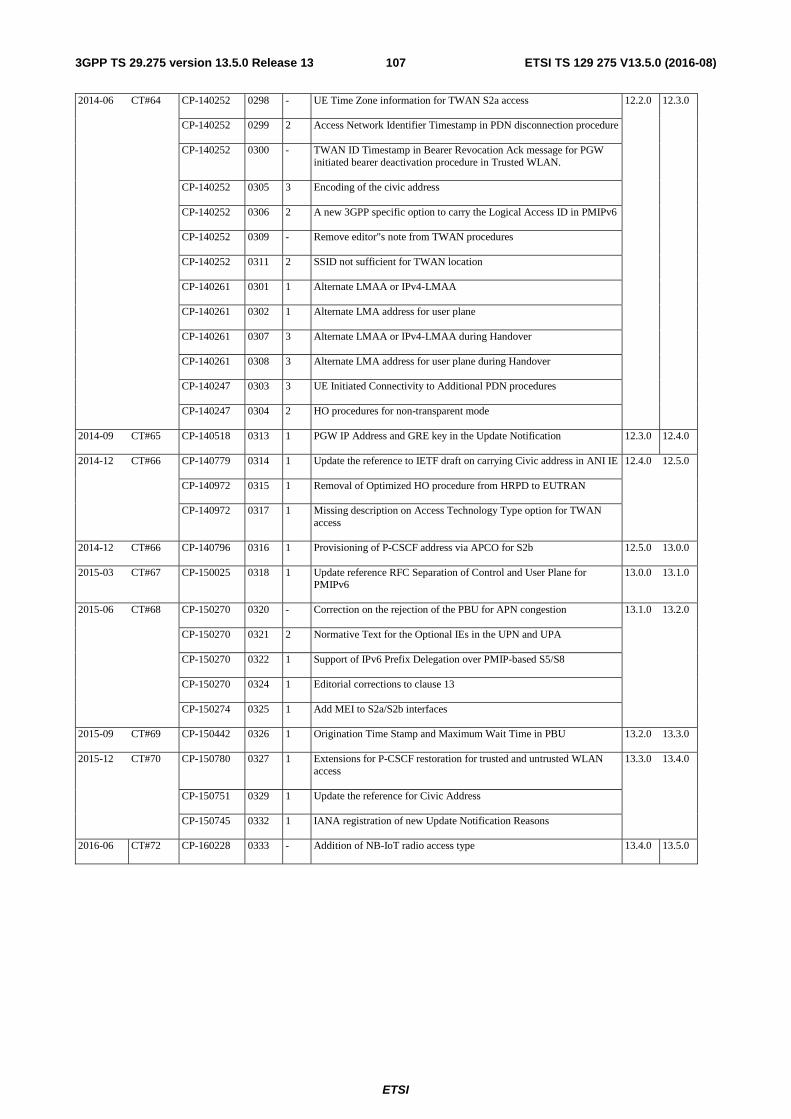
ETSI
ETSI TS 129 275 V13.5.0 (2016-08)1073GPP TS 29.275 version 13.5.0 Release 13
2014-06 CT#64 CP-140252 0298 - UE Time Zone information for TWAN S2a access 12.2.0 12.3.0
CP-140252 0299 2 Access Network Identifier Timestamp in PDN disconnection procedure
CP-140252 0300 - TWAN ID Timestamp in Bearer Revocation Ack message for PGW initiated bearer deactivation procedure in Trusted WLAN.
CP-140252 0305 3 Encoding of the civic address
CP-140252 0306 2 A new 3GPP specific option to carry the Logical Access ID in PMIPv6
CP-140252 0309 - Remove editor"s note from TWAN procedures
CP-140252 0311 2 SSID not sufficient for TWAN location
CP-140261 0301 1 Alternate LMAA or IPv4-LMAA
CP-140261 0302 1 Alternate LMA address for user plane
CP-140261 0307 3 Alternate LMAA or IPv4-LMAA during Handover
CP-140261 0308 3 Alternate LMA address for user plane during Handover
CP-140247 0303 3 UE Initiated Connectivity to Additional PDN procedures
CP-140247 0304 2 HO procedures for non-transparent mode
2014-09 CT#65 CP-140518 0313 1 PGW IP Address and GRE key in the Update Notification 12.3.0 12.4.0
2014-12 CT#66 CP-140779 0314 1 Update the reference to IETF draft on carrying Civic address in ANI IE 12.4.0 12.5.0
CP-140972 0315 1 Removal of Optimized HO procedure from HRPD to EUTRAN
CP-140972 0317 1 Missing description on Access Technology Type option for TWAN access
2014-12 CT#66 CP-140796 0316 1 Provisioning of P-CSCF address via APCO for S2b 12.5.0 13.0.0
2015-03 CT#67 CP-150025 0318 1 Update reference RFC Separation of Control and User Plane for PMIPv6
13.0.0 13.1.0
2015-06 CT#68 CP-150270 0320 - Correction on the rejection of the PBU for APN congestion 13.1.0 13.2.0
CP-150270 0321 2 Normative Text for the Optional IEs in the UPN and UPA
CP-150270 0322 1 Support of IPv6 Prefix Delegation over PMIP-based S5/S8
CP-150270 0324 1 Editorial corrections to clause 13
CP-150274 0325 1 Add MEI to S2a/S2b interfaces
2015-09 CT#69 CP-150442 0326 1 Origination Time Stamp and Maximum Wait Time in PBU 13.2.0 13.3.0
2015-12 CT#70 CP-150780 0327 1 Extensions for P-CSCF restoration for trusted and untrusted WLAN access
13.3.0 13.4.0
CP-150751 0329 1 Update the reference for Civic Address
CP-150745 0332 1 IANA registration of new Update Notification Reasons
2016-06 CT#72 CP-160228 0333 - Addition of NB-IoT radio access type 13.4.0 13.5.0

ETSI
ETSI TS 129 275 V13.5.0 (2016-08)1083GPP TS 29.275 version 13.5.0 Release 13
History
Document history
V13.4.0 March 2016 Publication
V13.5.0 August 2016 Publication